WO2025004575A1 - 作業車両 - Google Patents
作業車両 Download PDFInfo
- Publication number
- WO2025004575A1 WO2025004575A1 PCT/JP2024/017825 JP2024017825W WO2025004575A1 WO 2025004575 A1 WO2025004575 A1 WO 2025004575A1 JP 2024017825 W JP2024017825 W JP 2024017825W WO 2025004575 A1 WO2025004575 A1 WO 2025004575A1
- Authority
- WO
- WIPO (PCT)
- Prior art keywords
- piping
- tank
- frame
- fuel cell
- work vehicle
- Prior art date
- Legal status (The legal status is an assumption and is not a legal conclusion. Google has not performed a legal analysis and makes no representation as to the accuracy of the status listed.)
- Ceased
Links
Images




Classifications
-
- B—PERFORMING OPERATIONS; TRANSPORTING
- B60—VEHICLES IN GENERAL
- B60K—ARRANGEMENT OR MOUNTING OF PROPULSION UNITS OR OF TRANSMISSIONS IN VEHICLES; ARRANGEMENT OR MOUNTING OF PLURAL DIVERSE PRIME-MOVERS IN VEHICLES; AUXILIARY DRIVES FOR VEHICLES; INSTRUMENTATION OR DASHBOARDS FOR VEHICLES; ARRANGEMENTS IN CONNECTION WITH COOLING, AIR INTAKE, GAS EXHAUST OR FUEL SUPPLY OF PROPULSION UNITS IN VEHICLES
- B60K15/00—Arrangement in connection with fuel supply of combustion engines or other fuel consuming energy converters, e.g. fuel cells; Mounting or construction of fuel tanks
- B60K15/03—Fuel tanks
- B60K15/063—Arrangement of tanks
- B60K15/067—Mounting of tanks
- B60K15/07—Mounting of tanks of gas tanks
-
- B—PERFORMING OPERATIONS; TRANSPORTING
- B60—VEHICLES IN GENERAL
- B60K—ARRANGEMENT OR MOUNTING OF PROPULSION UNITS OR OF TRANSMISSIONS IN VEHICLES; ARRANGEMENT OR MOUNTING OF PLURAL DIVERSE PRIME-MOVERS IN VEHICLES; AUXILIARY DRIVES FOR VEHICLES; INSTRUMENTATION OR DASHBOARDS FOR VEHICLES; ARRANGEMENTS IN CONNECTION WITH COOLING, AIR INTAKE, GAS EXHAUST OR FUEL SUPPLY OF PROPULSION UNITS IN VEHICLES
- B60K1/00—Arrangement or mounting of electrical propulsion units
-
- B—PERFORMING OPERATIONS; TRANSPORTING
- B60—VEHICLES IN GENERAL
- B60K—ARRANGEMENT OR MOUNTING OF PROPULSION UNITS OR OF TRANSMISSIONS IN VEHICLES; ARRANGEMENT OR MOUNTING OF PLURAL DIVERSE PRIME-MOVERS IN VEHICLES; AUXILIARY DRIVES FOR VEHICLES; INSTRUMENTATION OR DASHBOARDS FOR VEHICLES; ARRANGEMENTS IN CONNECTION WITH COOLING, AIR INTAKE, GAS EXHAUST OR FUEL SUPPLY OF PROPULSION UNITS IN VEHICLES
- B60K1/00—Arrangement or mounting of electrical propulsion units
- B60K1/04—Arrangement or mounting of electrical propulsion units of the electric storage means for propulsion
-
- B—PERFORMING OPERATIONS; TRANSPORTING
- B60—VEHICLES IN GENERAL
- B60K—ARRANGEMENT OR MOUNTING OF PROPULSION UNITS OR OF TRANSMISSIONS IN VEHICLES; ARRANGEMENT OR MOUNTING OF PLURAL DIVERSE PRIME-MOVERS IN VEHICLES; AUXILIARY DRIVES FOR VEHICLES; INSTRUMENTATION OR DASHBOARDS FOR VEHICLES; ARRANGEMENTS IN CONNECTION WITH COOLING, AIR INTAKE, GAS EXHAUST OR FUEL SUPPLY OF PROPULSION UNITS IN VEHICLES
- B60K15/00—Arrangement in connection with fuel supply of combustion engines or other fuel consuming energy converters, e.g. fuel cells; Mounting or construction of fuel tanks
- B60K15/01—Arrangement of fuel conduits
-
- B—PERFORMING OPERATIONS; TRANSPORTING
- B60—VEHICLES IN GENERAL
- B60K—ARRANGEMENT OR MOUNTING OF PROPULSION UNITS OR OF TRANSMISSIONS IN VEHICLES; ARRANGEMENT OR MOUNTING OF PLURAL DIVERSE PRIME-MOVERS IN VEHICLES; AUXILIARY DRIVES FOR VEHICLES; INSTRUMENTATION OR DASHBOARDS FOR VEHICLES; ARRANGEMENTS IN CONNECTION WITH COOLING, AIR INTAKE, GAS EXHAUST OR FUEL SUPPLY OF PROPULSION UNITS IN VEHICLES
- B60K15/00—Arrangement in connection with fuel supply of combustion engines or other fuel consuming energy converters, e.g. fuel cells; Mounting or construction of fuel tanks
- B60K15/01—Arrangement of fuel conduits
- B60K15/013—Arrangement of fuel conduits of gas conduits
-
- B—PERFORMING OPERATIONS; TRANSPORTING
- B60—VEHICLES IN GENERAL
- B60K—ARRANGEMENT OR MOUNTING OF PROPULSION UNITS OR OF TRANSMISSIONS IN VEHICLES; ARRANGEMENT OR MOUNTING OF PLURAL DIVERSE PRIME-MOVERS IN VEHICLES; AUXILIARY DRIVES FOR VEHICLES; INSTRUMENTATION OR DASHBOARDS FOR VEHICLES; ARRANGEMENTS IN CONNECTION WITH COOLING, AIR INTAKE, GAS EXHAUST OR FUEL SUPPLY OF PROPULSION UNITS IN VEHICLES
- B60K15/00—Arrangement in connection with fuel supply of combustion engines or other fuel consuming energy converters, e.g. fuel cells; Mounting or construction of fuel tanks
- B60K15/03—Fuel tanks
- B60K15/04—Tank inlets
-
- B—PERFORMING OPERATIONS; TRANSPORTING
- B60—VEHICLES IN GENERAL
- B60K—ARRANGEMENT OR MOUNTING OF PROPULSION UNITS OR OF TRANSMISSIONS IN VEHICLES; ARRANGEMENT OR MOUNTING OF PLURAL DIVERSE PRIME-MOVERS IN VEHICLES; AUXILIARY DRIVES FOR VEHICLES; INSTRUMENTATION OR DASHBOARDS FOR VEHICLES; ARRANGEMENTS IN CONNECTION WITH COOLING, AIR INTAKE, GAS EXHAUST OR FUEL SUPPLY OF PROPULSION UNITS IN VEHICLES
- B60K15/00—Arrangement in connection with fuel supply of combustion engines or other fuel consuming energy converters, e.g. fuel cells; Mounting or construction of fuel tanks
- B60K15/03—Fuel tanks
- B60K15/063—Arrangement of tanks
-
- B—PERFORMING OPERATIONS; TRANSPORTING
- B60—VEHICLES IN GENERAL
- B60L—PROPULSION OF ELECTRICALLY-PROPELLED VEHICLES; SUPPLYING ELECTRIC POWER FOR AUXILIARY EQUIPMENT OF ELECTRICALLY-PROPELLED VEHICLES; ELECTRODYNAMIC BRAKE SYSTEMS FOR VEHICLES IN GENERAL; MAGNETIC SUSPENSION OR LEVITATION FOR VEHICLES; MONITORING OPERATING VARIABLES OF ELECTRICALLY-PROPELLED VEHICLES; ELECTRIC SAFETY DEVICES FOR ELECTRICALLY-PROPELLED VEHICLES
- B60L50/00—Electric propulsion with power supplied within the vehicle
- B60L50/50—Electric propulsion with power supplied within the vehicle using propulsion power supplied by batteries or fuel cells
- B60L50/70—Electric propulsion with power supplied within the vehicle using propulsion power supplied by batteries or fuel cells using power supplied by fuel cells
-
- B—PERFORMING OPERATIONS; TRANSPORTING
- B60—VEHICLES IN GENERAL
- B60L—PROPULSION OF ELECTRICALLY-PROPELLED VEHICLES; SUPPLYING ELECTRIC POWER FOR AUXILIARY EQUIPMENT OF ELECTRICALLY-PROPELLED VEHICLES; ELECTRODYNAMIC BRAKE SYSTEMS FOR VEHICLES IN GENERAL; MAGNETIC SUSPENSION OR LEVITATION FOR VEHICLES; MONITORING OPERATING VARIABLES OF ELECTRICALLY-PROPELLED VEHICLES; ELECTRIC SAFETY DEVICES FOR ELECTRICALLY-PROPELLED VEHICLES
- B60L50/00—Electric propulsion with power supplied within the vehicle
- B60L50/50—Electric propulsion with power supplied within the vehicle using propulsion power supplied by batteries or fuel cells
- B60L50/70—Electric propulsion with power supplied within the vehicle using propulsion power supplied by batteries or fuel cells using power supplied by fuel cells
- B60L50/71—Arrangement of fuel cells within vehicles specially adapted for electric vehicles
-
- B—PERFORMING OPERATIONS; TRANSPORTING
- B60—VEHICLES IN GENERAL
- B60K—ARRANGEMENT OR MOUNTING OF PROPULSION UNITS OR OF TRANSMISSIONS IN VEHICLES; ARRANGEMENT OR MOUNTING OF PLURAL DIVERSE PRIME-MOVERS IN VEHICLES; AUXILIARY DRIVES FOR VEHICLES; INSTRUMENTATION OR DASHBOARDS FOR VEHICLES; ARRANGEMENTS IN CONNECTION WITH COOLING, AIR INTAKE, GAS EXHAUST OR FUEL SUPPLY OF PROPULSION UNITS IN VEHICLES
- B60K15/00—Arrangement in connection with fuel supply of combustion engines or other fuel consuming energy converters, e.g. fuel cells; Mounting or construction of fuel tanks
- B60K15/03—Fuel tanks
- B60K2015/03309—Tanks specially adapted for particular fuels
- B60K2015/03315—Tanks specially adapted for particular fuels for hydrogen
-
- B—PERFORMING OPERATIONS; TRANSPORTING
- B60—VEHICLES IN GENERAL
- B60K—ARRANGEMENT OR MOUNTING OF PROPULSION UNITS OR OF TRANSMISSIONS IN VEHICLES; ARRANGEMENT OR MOUNTING OF PLURAL DIVERSE PRIME-MOVERS IN VEHICLES; AUXILIARY DRIVES FOR VEHICLES; INSTRUMENTATION OR DASHBOARDS FOR VEHICLES; ARRANGEMENTS IN CONNECTION WITH COOLING, AIR INTAKE, GAS EXHAUST OR FUEL SUPPLY OF PROPULSION UNITS IN VEHICLES
- B60K15/00—Arrangement in connection with fuel supply of combustion engines or other fuel consuming energy converters, e.g. fuel cells; Mounting or construction of fuel tanks
- B60K15/03—Fuel tanks
- B60K15/063—Arrangement of tanks
- B60K2015/0634—Arrangement of tanks the fuel tank is arranged below the vehicle floor
-
- B—PERFORMING OPERATIONS; TRANSPORTING
- B60—VEHICLES IN GENERAL
- B60K—ARRANGEMENT OR MOUNTING OF PROPULSION UNITS OR OF TRANSMISSIONS IN VEHICLES; ARRANGEMENT OR MOUNTING OF PLURAL DIVERSE PRIME-MOVERS IN VEHICLES; AUXILIARY DRIVES FOR VEHICLES; INSTRUMENTATION OR DASHBOARDS FOR VEHICLES; ARRANGEMENTS IN CONNECTION WITH COOLING, AIR INTAKE, GAS EXHAUST OR FUEL SUPPLY OF PROPULSION UNITS IN VEHICLES
- B60K15/00—Arrangement in connection with fuel supply of combustion engines or other fuel consuming energy converters, e.g. fuel cells; Mounting or construction of fuel tanks
- B60K15/03—Fuel tanks
- B60K15/063—Arrangement of tanks
- B60K2015/0638—Arrangement of tanks the fuel tank is arranged in the rear of the vehicle
-
- B—PERFORMING OPERATIONS; TRANSPORTING
- B60—VEHICLES IN GENERAL
- B60L—PROPULSION OF ELECTRICALLY-PROPELLED VEHICLES; SUPPLYING ELECTRIC POWER FOR AUXILIARY EQUIPMENT OF ELECTRICALLY-PROPELLED VEHICLES; ELECTRODYNAMIC BRAKE SYSTEMS FOR VEHICLES IN GENERAL; MAGNETIC SUSPENSION OR LEVITATION FOR VEHICLES; MONITORING OPERATING VARIABLES OF ELECTRICALLY-PROPELLED VEHICLES; ELECTRIC SAFETY DEVICES FOR ELECTRICALLY-PROPELLED VEHICLES
- B60L2200/00—Type of vehicles
- B60L2200/40—Working vehicles
Definitions
- the present invention relates to a work vehicle.
- This application claims priority to Japanese Application No. 2023-107681, filed on June 30, 2023, and incorporates by reference all of the contents of said Japanese application.
- Patent Document 1 discloses a work vehicle that has a tank for storing hydrogen gas, a fuel cell, and a motor.
- the fuel cell generates electricity using the hydrogen gas in the tank, and the motor rotates using that electricity.
- the work vehicle runs using the rotational force of the motor as a driving force.
- a work vehicle has a vehicle body, a tank unit having a tank for storing hydrogen gas and mounted on the vehicle body, a fuel cell mounted on the vehicle body, and piping for hydrogen gas connecting the tank and the fuel cell, and a piping area through which the piping connecting to the tank passes is provided at the bottom of the tank unit.
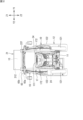
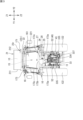
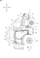
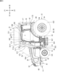
- FIG. 1 is a perspective view showing an embodiment of a work vehicle according to the present disclosure.
- FIG. 2 is a front view of the work vehicle shown in FIG.
- FIG. 3 is a rear view of the work vehicle shown in FIG.
- FIG. 4 is a side view of the work vehicle shown in FIG.
- FIG. 5 is a side view of the work vehicle shown in FIG.
- FIG. 6 is a plan view of the work vehicle shown in FIG.
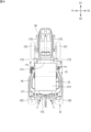
- FIG. 9 is a side view of the work vehicle with the hood and other components removed.
- FIG. 10 is a perspective view of the vehicle body with the right rear wheel removed.
- FIG. 10 is a perspective view of the vehicle body with the right rear wheel removed.
- FIG. 11 is a side view of the work vehicle shown in FIG. 5 with the rear wheels and the front frame removed.
- FIG. 12 is an explanatory diagram of the filler attached to the bracket and its surroundings.
- FIG. 13 is an explanatory diagram of the fuel cell and the exhaust path.
- FIG. 14 is a perspective view of the battery unit and the discharge pipe supported by the support structure.
- FIG. 15 is an exploded perspective view of the battery unit, the exhaust pipe, and the support structure.
- FIG. 16 is a front view of the battery unit and the discharge pipe supported by the support structure.
- FIG. 17 is a front view showing the battery unit separated from the support structure.
- a tank for storing hydrogen gas is provided above the vehicle body.
- Hydrogen equipment such as a fuel cell and a filling port for filling the vehicle with hydrogen gas, are mounted on the vehicle body.
- the tank and the hydrogen equipment are connected by piping. It is preferable to keep the piping as short as possible.
- the present disclosure therefore aims to provide a work vehicle that makes it possible to shorten as much as possible the piping connected to the tank that stores hydrogen gas.
- the work vehicle of this embodiment has a vehicle body, a tank unit having a tank for storing hydrogen gas and provided on the vehicle body, a fuel cell mounted on the vehicle body, and piping for hydrogen gas connecting the tank and the fuel cell, and a piping area through which the piping connecting to the tank passes is provided at the bottom of the tank unit.
- the tank unit is provided on the vehicle body.
- the piping area is provided below the tank unit.
- the piping area in the tank unit is located as close as possible to the fuel cell mounted on the vehicle body, making it possible to make the piping for hydrogen gas as short as possible.
- the work vehicle has, as the piping, a front piping that passes through the piping area below and at the front of the tank unit and is connected to the fuel cell. According to the above-mentioned configuration, it is possible to shorten the length of the upstream pipe connecting the tank to the fuel cell as much as possible.
- the work vehicle of (1) or (2) has a filling section and a rear piping that passes through the piping area below and at the rear of the tank unit and connects to the filling section. According to the above-mentioned configuration, it is possible to shorten the rear piping connecting the filling section to the tank as much as possible.
- the vehicle body has a cover that covers mounted items located toward the front of the vehicle body, and the cover has an opening through which the front piping passes.
- the front piping does not have to detour around the cover, and the front piping can be laid out as efficiently as possible.
- any one of the work vehicles (1) to (4) has a mounting frame for mounting the tank unit on the vehicle body, and the piping is attached along a portion of a columnar frame material of the mounting frame.
- a mounting frame is used to support piping between the tank unit and the hydrogen payload.
- the work vehicle of (5) above has a clamp member for fixing the piping to a part of the frame material.
- the clamp members secure the piping to the frame material and prevent it from shifting out of position.
- the frame material is a hollow tubular member, and at least a portion of the piping passes through the tubular member. According to the above-described configuration, the frame material (the tubular member) functions as a cover for protecting the piping.
- the work vehicle of (3) has a frame connected to the vehicle body, the frame has a clamp member for attaching the rear piping to a part of the frame, and the frame has an attachment portion for attaching the filling portion.
- the frame connected to the vehicle body serves as a fixing member for the rear piping by the clamp member and also serves as a mounting member for the filling portion.
- the frame is part of a mounting frame for mounting the tank on the vehicle body.
- the mounting frame for mounting the tank unit on the vehicle body is also used as a member for attaching the hydrogen gas filling section to the vehicle body.
- the piping has a flexible piping in part.
- the piping can be easily attached to the work vehicle. After the piping is attached, even if an external force is applied to the piping due to vibration or the like, the force can be absorbed.
- the work vehicle includes a hydrogen gas filling section located behind the tank, the fuel cell located in front of the tank, a rear pipe connecting the filling section and the tank, and a front pipe connecting the tank and the fuel cell.
- the piping region for the rear piping is located on the first side in a vehicle width direction
- the piping region for the front piping is located on the second side in the vehicle width direction.
- the hydrogen gas filled from the filling section is supplied to the tank through the rear piping that passes through the piping area on the first side in the vehicle width direction.
- the hydrogen gas is supplied to the fuel cell through the front piping that passes through the piping area on the other side in the vehicle width direction. It is possible to efficiently layout the rear piping and the front piping in the tank unit.
- FIG. 1 is a perspective view showing an embodiment of a work vehicle according to the present disclosure.
- Fig. 2 to Fig. 7 are a front view, a rear view, a side view (left side view), a side view (right side view), a plan view, and a bottom view of the work vehicle shown in Fig. 1.
- the work vehicle 10 of this embodiment is a vehicle that can be used for agricultural work, and the work vehicle 10 shown in Fig. 1 is a tractor.
- the work vehicle is not limited to a tractor.
- the work vehicle according to the present invention may be an agricultural machine, a construction machine, a utility vehicle, or the like other than a tractor.
- the directions of the work vehicle 10 of the present disclosure are defined below.
- the direction in which the work vehicle 10 moves forward is defined as “front”
- the direction in which the work vehicle 10 moves backward is defined as “back”
- the left side when facing forward is defined as “left”
- the right side when facing forward is defined as “right”.
- the left-right direction perpendicular to the front-to-rear direction is defined as the vehicle width direction.
- the direction perpendicular to both the front-to-rear direction and the vehicle width direction (left-to-right direction) is defined as the up-down direction.
- the up-down direction is also called the height direction.
- an orthogonal three-dimensional coordinate system is shown, with the forward direction indicated by an arrow X1, the backward direction indicated by an arrow X2, the left direction indicated by an arrow Y1, the right direction indicated by an arrow Y2, the up direction indicated by an arrow Z1, and the down direction indicated by an arrow Z2.
- the work vehicle 10 shown in FIG. 1 has a vehicle body 11, a running device 12 that supports the vehicle body 11 so that it can run, a driver's seat 15, a cabin 16, a tank unit 21 having a tank 13 for storing fuel, and a drive device 14 that is powered by the fuel stored in the tank 13.
- the fuel is hydrogen
- the tank 13 is a hydrogen tank that stores hydrogen gas.
- the work vehicle 10 of this embodiment is a fuel cell vehicle (FCV), and runs on electricity generated by a fuel cell (fuel cell module) 24 using hydrogen and oxygen.
- FCV fuel cell vehicle
- the work vehicle 10 has a fuel cell 24, a battery unit 30, and an electric motor 31 as the drive device 14.
- the battery unit 30 has a battery 300 that stores the power generated by the fuel cell 24, and supplies the stored power to the motor 31.
- the work vehicle 10 has a piping (hydrogen piping) 22 for hydrogen gas, and a filling section 25 (see FIG. 3).
- the filling section 25 has a filling port (receptacle) 26 to which a filling nozzle of a hydrogen gas supply device (not shown) that is separate from the work vehicle 10 is connected. Hydrogen gas is supplied from the filling port 26 and supplied to the tank 13 through the piping 22 (rear piping 22r). The hydrogen gas in the tank 13 is supplied to the fuel cell 24 through the piping 22 (front piping 22f).
- the specific configurations of the filling section 25 and the piping 22 will be described later.
- the work vehicle 10 (see FIG. 1) has a mounting frame 17 and a support structure 37.
- the mounting frame 17 is a frame for mounting the tank unit 21 (tank 13) on the vehicle body 11.
- the support structure 37 is a component for supporting the battery unit 30 on the vehicle body 11.
- the work vehicle 10 (see FIG. 7) has an exhaust path 35.
- the exhaust path 35 exhausts water or water vapor generated by the operation of the fuel cell 24 to the outside.
- FIG. 8 is an exploded perspective view of a part of the work vehicle 10 shown in FIG. 1.
- the chassis 41 is located at the center in the vehicle width direction and has a shape that is long in the vehicle front-rear direction.
- the chassis 41 has a front frame 32 that constitutes the front part of the chassis 41, and a gear case 33 that constitutes the rear part of the chassis 41.
- the front frame 32 is formed by combining metal frame materials and the like, and has high rigidity.
- the gear case 33 is formed by having a metal box body.
- the gear case 33 is connected to the rear part of the front frame 32, and the gear case 33 and the front frame 32 form the framework of the vehicle body 11.
- the front frame 32 mounts the motor 31.
- the gear case 33 has therein a power transmission mechanism 333 such as a transmission, a clutch, a differential gear, etc.
- the power transmission mechanism 333 reduces or increases the speed of rotation of the output shaft of the motor 31, and outputs the rotation to the traveling device 12 (one or both of the front wheels 121 and the rear wheels 122).
- the gear case 33 has a main case 337 located in the center in the vehicle width direction, and axle cases 335 for the rear wheels 122 located on both sides in the vehicle width direction at the rear of the main case 337.
- the main case 337 and the axle cases 335 are made of, for example, cast steel and have high rigidity.
- the power transmission mechanism 333 outputs a portion of the power of the motor 31 to the PTO shaft 334 (see FIG. 3).
- the PTO shaft 334 is an output shaft provided at the rear of the gear case 33.
- the work vehicle 10 has a coupling device 43 for coupling another device to the rear of the vehicle body 11.
- the PTO shaft 334 transmits the power of the motor 31 to the other device coupled to the coupling device 43.
- the other device is a work device (not shown), also called an implement.
- the work device is operated by the power of the motor 31.
- the work device is, for example, a tiller.
- FIG. 9 is a left side view of the work vehicle 10 with the bonnet 34, cover 111, and part of the tank case 211 of the tank unit 21 removed.
- a first radiator 48, a fuel cell 24, and a second radiator 49 are mounted on the chassis 41 in this order.
- the bonnet 34 and the cover 111 cover mounted components located toward the front of the vehicle body 11.
- the bonnet 34 covers the fuel cell 24 and the first radiator 48 from above and from both sides in the vehicle width direction.
- the cover 111 covers the second radiator 49 located behind the fuel cell 24 from above and from both sides in the vehicle width direction.
- An upper surface 48a of the first radiator 48 is lower than an upper surface 24a of the fuel cell 24.
- the upper surface 24a of the fuel cell 24 is lower than an upper surface 49a of the second radiator 49.
- the top surface 111a of the cover 111 is higher than the top surface 34a of the bonnet 34, but lower than the top end of the steering wheel 151 that is operated for steering by an operator sitting in the driver's seat 15.
- the top surface 34a of the bonnet 34 becomes lower toward the front. For this reason, the view of the operator sitting in the driver's seat 15 is less likely to be obstructed.
- the driver's seat 15 and the cabin 16 are provided on the chassis 41 at a rearward position (see FIG. 1).
- the cabin 16 has the driver's seat 15 therein.
- the cabin 16 has a front pillar 162 located forward of the driver's seat 15, a rear pillar 163 located behind the front pillar 162, and a roof 164 located above the driver's seat 15.
- the front pillar 162 is provided on the left front and right front of the driver's seat 15.
- the rear pillar 163 is provided on the left rear and right rear of the driver's seat 15.
- the roof 164 is supported by the front pillar 162 and the rear pillar 163.
- the cabin 16 has a windshield 165 located in front of the driver's seat 15.
- the windshield 165 is provided between the left and right front pillars 162.
- the cabin 16 has openable and closable doors 166 on both sides in the vehicle width direction.
- the doors 166 are provided between the front pillars 162 and the rear pillars 163.
- a step 167 (see FIG. 5 ) is provided on one side (left side) of the cabin 16 in the vehicle body width direction.
- the step 167 is a member on which an operator who gets on and off the cabin 16 places his or her feet.
- a cover 111 and a bonnet 34 are provided in front of the cabin 16. As shown in Fig. 2 and Fig. 6, the dimensions of the cover 111 and the bonnet 34 in the vehicle width direction are each smaller than the dimension of the cabin 16 in the vehicle width direction. The dimension of the bonnet 34 in the vehicle width direction is smaller than the dimension of the cover 111 in the vehicle width direction.
- the work vehicle 10 of this embodiment has a cabin 16, but does not necessarily have to have the cabin 16.
- the work vehicle 10 may have a canopy or ropes instead of the cabin 16. If the work vehicle 10 does not have a cabin 16, the tank unit 21 is supported by the mounting frame 17 and positioned above the driver's seat 15.
- the traveling device 12 has front wheels 121 and rear wheels 122 (see FIG. 6 ).
- the front wheels 121 are provided on the left and right sides of the front part of the vehicle body 11.
- the rear wheels 122 are provided on the left and right sides of the rear part of the vehicle body 11.
- the maximum dimension in the vehicle width direction of the left and right rear wheels 122 is greater than the maximum dimension in the vehicle width direction of the left and right front wheels 121.
- the maximum dimension in the vehicle width direction of the left and right rear wheels 122 becomes the maximum vehicle width dimension of the work vehicle 10.
- One or both of the front wheels 121 and the rear wheels 122 rotate by the power of the motor 31.
- One or both of the front wheels 121 and the rear wheels 122 (drive wheels) that rotate by the power of the motor 31 may be crawlers (crawlers).
- the drive device 14 is configured to include the fuel cell 24 , the battery unit 30 , and the motor 31 .
- the fuel cell 24 is located on a chassis 41 near the front of the vehicle body 11 (see FIG. 9).
- the motor 31 is located behind the fuel cell 24 (see FIG. 8).
- the battery unit 30 is located toward the outer side in the vehicle width direction of the vehicle body 11 (see FIG. 1).
- the battery unit 30 is attached to the chassis 41 by a support structure 37.
- the fuel cell 24 generates electricity using hydrogen gas as fuel. In other words, the fuel cell 24 generates electricity using hydrogen gas to obtain the electricity to rotate the motor 31.
- the fuel cell 24 (see FIG. 9) has a battery casing 241 that is substantially rectangular box-shaped, and a fuel cell stack 242 that is provided inside the battery casing 241.
- the fuel cell stack 242 has multiple battery cells.
- the battery cell has a positive electrode and a negative electrode. Multiple single cells are stacked. The electricity generated by each battery cell is collected and output to the battery unit 30.
- the motor 31 has a rotating rotor and a stator having multiple coils.
- the output shaft of the motor 31 is connected to a power transmission mechanism 333 in the gear case 33 (see FIG. 8).
- the motor 31 is located behind the fuel cell 24 and below the second radiator 49 (see FIG. 9).
- the tank unit 21 has a tank 13 and a tank case 211 that houses the tank 13.
- the tank 13 is a substantially cylindrical high-pressure container.
- the tank 13 is made of fiber-reinforced resin reinforced with carbon fiber or glass fiber, or the like.
- three tanks 13 are fixed to the tank case 211 with the axial direction of their cylindrical portions parallel to the vehicle width direction.
- the number of tanks 13 is not limited to three.
- the tank case 211 is a box capable of housing one or more tanks 13.
- the tank case 211 has a box shape that covers the entire tank 13 it houses.
- the tank case 211 has an opening/closing door 213 (see FIG. 1) on one or both sides in the vehicle width direction, and opens in the vehicle width direction.
- the tank case 211 is installed above the roof 164, spaced apart from the roof 164 in the vertical direction.
- the tank case 211 is fixed to the upper frame portion 171 of the mounting frame 17.
- the tank case 211 is made of metal such as aluminum or steel, and protects the tank 13 from external thermal and physical influences.
- the tank 13 is positioned above the cabin 16 (driver's seat 15). This allows for a high degree of freedom in the placement of the fuel cell 24, charging section 25, motor 31, and battery unit 30 in the vehicle body 11.
- a conventional work vehicle with an internal combustion engine into a work vehicle 10 having a fuel cell 24 and motor 31 as in this embodiment, there is no need to significantly change the placement and configuration of each piece of equipment.
- the tank 13 is connected to the rear pipe 22r and the front pipe 22f via the valve unit 212 (see FIG. 9).
- the rear pipe 22r (see FIG. 3) is a gas inlet pipe that connects the hydrogen gas filling port 26 to the valve unit 212, and guides the hydrogen gas introduced into the filling port 26 to the tank 13.
- the front pipe 22f (see FIG. 2) is a gas outlet pipe that connects the fuel cell 24 to the valve unit 212, and guides the hydrogen gas stored in the tank 13 to the fuel cell 24.
- the tank 13 stores the hydrogen gas introduced into the filling port 26 from outside the vehicle and supplies it to the fuel cell 24.
- the valve unit 212 has an opening/closing valve, a pressure reducing valve, etc., and adjusts the hydrogen gas stored in the tank 13 to a predetermined flow rate and guides it to the fuel cell 24 through the front pipe 22f.
- the mounting frame 17 (see FIG. 1 ) is a frame structure for mounting the tank 13 on the vehicle body 11.
- the mounting frame 17 is made of steel.
- the mounting frame 17 in this embodiment has an upper frame portion 171 that supports the tank 13, and a first front frame portion 172, a second front frame portion 175, and a rear frame portion 173 as frames for supporting the upper frame portion 171.
- a tank case 211 is attached to the upper frame portion 171.
- the upper frame portion 171 supports the tank 13 via the tank case 211.
- the specific configuration of the mounting frame 17 will be described later.
- the filling section 25 is provided on the rear frame section 173 (see FIG. 3).
- the filling section 25 has a filling port 26 to which a gas filling nozzle of a hydrogen gas supply device (not shown) installed outside the vehicle is connected when filling the tank 13 with hydrogen gas.
- the work vehicle 10 (see FIGS. 4 and 5) has a cooling system that uses a coolant to cool the fuel cell 24, the motor 31, the boost circuit 80, the inverter 81, the DC/DC converters 82, 83, etc.
- the work vehicle 10 has a first radiator 48 and a second radiator 49. As shown in FIG. 9, the first radiator 48 is located in front of the fuel cell 24, and the second radiator 49 is located behind the fuel cell 24.
- the first radiator 48 is a radiator for cooling devices other than the fuel cell 24.
- the second radiator 49 is a radiator for cooling the fuel cell 24.
- the first radiator 48 is connected, via a first cooling flow path (not shown) having a circulation pump, to electrical equipment (heat-generating components) that require cooling, such as the motor 31, the boost circuit 80 (see FIG. 5), the inverter 81, and the DC/DC converters 82, 83.
- the first radiator 48 cools the coolant supplied through the first cooling flow path by heat exchange with the outside air.
- the second radiator 49 is connected to the fuel cell 24 via a second cooling passage (not shown) having a circulation pump.
- the second radiator 49 cools the coolant supplied through the second cooling passage by heat exchange with the outside air.
- the first radiator 48 has a first fan 481 (see FIG. 9).
- the second radiator 49 has a second fan 491.
- the first fan 481 and the second fan 491 rotate to pass air through the first radiator 48 and the second radiator 49, promoting heat exchange with the coolant.
- the battery unit 30 stores the electric power generated by the fuel cell 24 and supplied to the motor 31.
- the battery unit 30 has a battery (battery pack) 300 and a housing 307 that houses the battery 300.
- the battery 300 temporarily stores the electric power generated by the fuel cell 24 and outputs the stored electric power to electrical devices such as the motor 31.
- the battery 300 is composed of multiple battery cells.
- the battery 300 is a charge-discharge type secondary battery such as a lithium ion battery or a lead storage battery.
- the work vehicle 10 has a junction box 75.
- the junction box 75 is an electric connection box for relaying and connecting and distributing the electric power output from the battery unit 30.
- the fuel cell 24 is connected to an inverter 81 (see FIG. 5 ) via a boost circuit.
- the battery unit 30 is connected to the inverter 81 through a junction box 75.
- the inverter 81 is electrically connected to the motor 31.
- the inverter 81 converts the DC power output from the boost circuit into three-phase AC power and outputs it to the motor 31.
- the work vehicle 10 has low-voltage electrical equipment that operates at a lower voltage than the motor 31.
- the low-voltage electrical equipment is supplied with power stepped down by a step-down circuit through a junction box 75.
- the low-voltage electrical equipment of the work vehicle 10 is the battery unit 30, radiators 48, 49, and air conditioning device 74 (see FIG. 9).
- the work vehicle 10 has a first DC/DC converter 82 and a second DC/DC converter 83 as the step-down circuit (see FIG. 5).
- the work vehicle 10 has a positioning device 65 (see FIG. 2).
- the positioning device 65 receives satellite signals transmitted from multiple GNSS satellites and performs positioning based on the satellite signals.
- GNSS is a general term for satellite positioning systems such as GPS (Global Positioning System), QZSS (Quasi-Zenith Satellite System: e.g., "Michibiki"), GLONASS ( Russia), Galileo (Europe), and BeiDou (China).
- the positioning device 65 has a receiver 65a that receives satellite signals, and a calculation processing unit 65b.
- the receiver 65a has an antenna that receives signals from GNSS satellites.
- the calculation processing unit 65b calculates and determines the position (coordinates) of the work vehicle 10 based on the signals received by the receiver 65a. In this way, the positioning device 65 obtains position information that indicates the position of the work vehicle 10.
- the mounting frame 17 (see Figs. 1 and 8) is a member for mounting the tank 13, which stores hydrogen gas, on the vehicle body 11.
- the mounting frame 17 is fixed to the vehicle body 11.
- the vehicle body 11 has a first front support portion 51, a second front support portion 53, and a rear support portion 52 (see Fig. 10) as support portions.
- Fig. 10 is a perspective view of the vehicle body 11 with the right rear wheel 122 removed.
- the first front support parts 51 are located on the front side of the vehicle body 11, on both sides in the vehicle width direction.
- the second front support parts 53 are located in front of the front support parts 51, on both sides in the vehicle width direction.
- the first front support parts 51 and the second front support parts 53 are beam-shaped members that protrude from the front frame 32 on both sides in the vehicle width direction.
- the vehicle body 11 has the front frame 32 and the gear case 33.
- the gear case 33 has a main case 337 located in the center in the vehicle width direction, and an axle case 335 for the rear wheels 122.
- the axle case 335 is fixed to the main case 337.
- the rear support portions 52 are located on both sides in the vehicle width direction at the rear of the vehicle body 11. In the present embodiment, the rear support portions 52 are connecting brackets 46 fixed onto the axle case 335.
- the mounting frame 17 (see FIGS. 1 and 8 ) has an upper frame portion 171 , a pair of left and right first front frame portions 172 , a pair of left and right second front frame portions 175 , and a pair of rear frame portions 173 .
- the upper frame portion 171 is a rectangular frame constituted by four straight members on the front, rear, left and right sides.
- the upper frame portion 171 supports the tank 13.
- a tank case 211 is attached to the upper frame portion 171, and the tank 13 is housed inside the tank case 211.
- the first front frame portions 172 are pillar members that extend upward from the front support portions 51 on both sides in the vehicle width direction.
- the pair of first front frame portions 172 are connected to both sides in the vehicle width direction of the front portion 171f of the upper frame portion 171.
- the pair of first front frame portions 172 support the front portion 171f of the upper frame portion 171 from below on both sides in the vehicle width direction.
- the first front frame portions 172 have a linear shape that extends from the front support portions 51 toward the upper frame portion 171.
- the rear frame portion 173 is composed of multiple straight members.
- the rear frame portion 173 extends upward from each of the rear support portions 52 (connecting brackets 46 shown in FIG. 10) on both sides in the vehicle width direction.
- the rear frame portion 173 is connected to both sides in the vehicle width direction of the rear portion 171r of the upper frame portion 171.
- the rear frame portion 173 supports the rear portion 171r of the upper frame portion 171 from below on both sides in the vehicle width direction.
- the upper frame portion 171 supporting the tank 13 is supported on both sides in the vehicle width direction by the chassis 41 via a first front frame portion 172 and a rear frame portion 173.
- the load of the tank 13 is supported by the chassis 41 through the mounting frame 17.
- a portion of the weight of the tank 13 is supported by the first front frame portion 172.
- the first front frame portion 172 is a long member, but has a linear shape and does not have any bent portions along the way, and is therefore unlikely to buckle even when a compressive force is applied.
- the second front frame portion 175 (see Figures 1 and 8) is a pillar member that extends upward and rearward from each of the second front support portions 53 on both sides in the vehicle width direction.
- the pair of second front frame portions 175 are connected to both sides in the vehicle width direction of the front portion 171f of the upper frame portion 171.
- the second front frame portion 175 may be connected to the upper portion of the first front frame portion 172 instead of the upper frame portion 171.
- the first front frame portion 172 and the second front frame portion 175 are fixed to the front frame 32 , which is part of the chassis 41 , via the first front support portion 51 and the second front support portion 53 , respectively.
- the rear support portion 52 is fixed to an axle case 335 of the gear case 33 , which is another part of the chassis 41 , via the rear support portion 52 (connecting bracket 46 ).
- the chassis 41 forms a framework for mounting the bonnet 34, the drive unit 14, etc., and has a strong structure and high rigidity.
- the tank 13 is supported by the chassis 41 via the mounting frame 17, allowing the work vehicle 10 to travel stably.
- the mounting frame 17 has a pair of inclined frame portions 174.
- the inclined frame portions 174 extend rearward and upward from a portion 172p of the first front frame portion 172, and are connected to a portion 171b of the upper frame portion 171.
- the inclined frame portions 174 are straight members.
- the inclined frame portions 174 increase the rigidity of the mounting frame 17 in the fore-and-aft direction of the vehicle.
- the rear frame portion 173 (see FIG. 10) has a pair of first frame members 173a, beam members 173b, and a pair of second frame members 173c.
- the pair of first frame members 173a extend upward from each of the rear support portions 52 (connecting brackets 46) on both sides in the vehicle width direction.
- the beam members 173b connect the pair of first frame members 173a in the vehicle width direction.
- the pair of second frame members 173c extend upward from positions on both sides of the beam members 173b in the vehicle width direction, and connect to the rear portions 171r of the upper frame portion 171.
- the rear frame portion 173 is reinforced by the beam members 173b.
- the spacing between the pair of first frame members 173a and the spacing between the pair of second frame members 173c are different.
- the pair of first frame members 173a are located between the rear wheels 122 on both sides in the vehicle width direction, and the spacing between them is narrow.
- the pair of second frame members 173c are located behind the driver's seat 15, and the spacing between them is wide to ensure visibility.
- the cabin 16 has a rear window 161 that opens rearward with its upper portion as a fulcrum.
- the pair of second frame members 173c are spaced widely apart in the vehicle width direction and are positioned on both sides in the vehicle width direction of the rear window 161 when it is open. The opening and closing of the rear window 161 is not hindered by the rear frame portion 173.
- the first frame member 173a extends upward and rearward from the rear support portion 52.
- the second frame member 173c extends upward and forward from the beam member 173b.
- the rear frame portion 173 has a shape that matches the shape of the rear of the work vehicle 10.
- the driver's seat 15 is mounted on a mount 168 of the cabin 16.
- the gear case 33 forming the rear of the chassis 41 has an axle case 335 for the rear wheels 122.
- a connecting bracket 46 is fixed onto the axle case 335.
- the connecting bracket 46 has an elastic bushing 45.
- the mount 168 on which the driver's seat 15 is placed is attached to the connecting bracket 46 via the elastic bushing 45.
- the driver's seat 15 is mounted on the chassis 41 (axle case 335) via the connecting bracket 46 which has the elastic bushing 45.
- the rear frame portion 173 of the mounting frame 17 is directly fixed to the chassis 41 (axle case 335) via the connecting bracket 46 (rear support portion 52).
- the first front frame portion 172 and the second front frame portion 175 of the mounting frame 17 are also directly fixed to the chassis 41 (front frame 32) via the first front support portion 51 and the second front support portion 53.
- the driver's seat 15 is mounted on the chassis 41 via the elastic bushing 45, whereas the mounting frame 17 is rigidly connected to the chassis 41.
- the chassis 41 and the mounting frame 17 form a single rigid body.
- the mounting frame 17 supporting the tank 13 does not wobble because it behaves in the same manner as the chassis 41.
- the elastic bushing 45 is interposed between the driver's seat 15 and the chassis 41, providing a comfortable ride.
- the connecting bracket 46 connects the rear frame portion 173, which is part of the mounting frame 17.
- the driver's seat 15 is attached to the connecting bracket 46 via an elastic bushing 45.
- the driver's seat 15 and the rear frame portion 173 are supported on the vehicle body 11 (chassis 41) via the connecting bracket 46.
- the connecting bracket 46 is shared as an attachment member for the driver's seat 15 and part of the mounting frame 17 (the rear frame portion 173).
- the upper frame portion 171 is located above the driver's seat 15 that is mounted on the vehicle body 11 (see FIGS. 4, 5 and 9).
- the work vehicle 10 has a cabin 16, and the upper frame portion 171 is located above the cabin 16.
- the first front frame portion 172 is located in front of the driver's seat 15 (cabin 16).
- the tank 13 is located above the driver's seat 15 (cabin 16) in a range to the rear of the first front frame portion 172 located in front of the driver's seat 15 (cabin 16).
- the rear frame portion 173 is located behind the driver's seat 15 (cabin 16).
- the tank 13 is located above the driver's seat 15 (cabin 16) in a forward range from the rear frame portion 173 located behind the driver's seat 15 (cabin 16).
- the distance between the first front frame portion 172 and the rear frame portion 173 is wide, allowing flexibility in the installation space of the tank 13.
- the tank 13 is housed in a tank case 211.
- the upper frame portion 171 is located above the cabin 16, and the front end 211f of the tank case 211 is located in front of the cabin 16. This arrangement allows the position of the tank 13 in the vehicle's fore-and-aft direction to be closer to the vehicle's center of gravity.
- the first front support portion 51 is located between the front wheel 121 and the rear wheel 122, and the first front frame portion 172 is located between the front wheel 121 and the rear wheel 122.
- the driver's seat 15 is mounted on the vehicle body 11 at a position behind the front wheels 121.
- the first front support portion 51 is located between the front wheels 121 and the driver's seat 15, and the first front frame portion 172 is located between the front wheels 121 and the driver's seat 15.
- the space between the front wheels 121 and the rear wheels 122 is effectively utilized, and in particular, the space between the front wheels 121 and the driver's seat 15 is effectively utilized.
- the first front frame portions 172 are located within a range in the vehicle width direction of the front wheels 121 on both sides in the vehicle width direction. The first front frame portions 172 do not protrude outward beyond the front wheels 121 in the vehicle width direction.
- the rear frame portion 173 is located within the vehicle width range of the rear wheels 122 on both sides in the vehicle width direction.
- the first frame members 173a of the rear frame portion 173 are located between the rear wheels 122 on both sides in the vehicle width direction.
- the rear frame portion 173 (see FIG. 4) is located within the range of the rear wheels 122 in the vehicle front-rear direction. As a result of the above, the rear frame portion 173 does not protrude outward in the vehicle width direction beyond the rear wheels 122, and does not protrude rearward beyond the rear wheels 122.
- the cabin 16 (see Figures 4 and 5) has a pair of front pillars 162 on both sides in the vehicle width direction, and a pair of rear pillars 163 on both sides in the vehicle width direction.
- the first front frame portion 172 is a separate member from the front pillars 162.
- the rear frame portion 173 is a separate member from the rear pillars 163. Therefore, the cabin 16 does not need to bear the weight of the tank 13, and the front pillars 162 and rear pillars 163 of the cabin 16 do not need to be made of highly rigid members.
- the first front frame portion 172 is located in front of the front pillar 162.
- the rear frame portion 173 is located behind the rear pillar 163. There is a wide gap between the first front frame portion 172 and the rear frame portion 173 in the fore-and-aft direction of the vehicle, and the cabin 16 is located between them.
- the tank unit 21 is located above the cabin 16.
- the front pipe 22f which is the hydrogen pipe 22
- the front pipe 22f is provided along the first front frame portion 172 of the mounting frame 17. Furthermore, the front pipe 22f is provided along the inclined frame portion 174.
- the rear pipe 22r which is the hydrogen pipe 22, is provided along the second frame material 173c of the rear frame portion 173.
- the first front frame portion 172, the inclined frame portion 174, and the rear frame portion 173 are used as members for attaching the hydrogen pipe 22.
- the hydrogen pipes 22 (front pipes 22 f and rear pipes 22 r ) connected to the tank 13 may be provided along at least one of the first front frame portion 172 and the rear frame portion 173 .
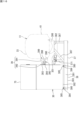
- Fig. 11 is a side view of the work vehicle 10 shown in Fig. 5 with the rear wheel 122 and the first front frame portion 172 removed. Note that in Fig. 11, the first front frame portion 172 is shown by a virtual line (two-dot chain line).
- the tank unit 21 has a tank 13 that stores hydrogen gas, and is provided on the vehicle body 11.
- the work vehicle 10 has a fuel cell 24 and a hydrogen gas filling unit 25 as hydrogen equipment mounted on the vehicle body 11.
- the fuel cell 24 is located in front of the tank 13. In other words, the fuel cell 24 is located toward the front of the vehicle body 11.
- the filling unit 25 is located behind the tank 13. In other words, the filling unit 25 is located toward the rear of the vehicle body 11.
- the work vehicle 10 has piping 22 for hydrogen gas that connects the tank 13 and the hydrogen payload (fuel cell 24, charging section 25).
- the piping 22 includes a rear piping 22r that connects the charging section 25 and the tank 13, and a front piping 22f that connects the tank 13 and the fuel cell 24.
- the front piping 22f passes through a piping area 23f at the lower and front part of the tank unit 21 and is connected to the fuel cell 24.
- the front piping 22f passes through the piping area 23f located on the lower surface of the tank unit 21.
- the rear piping 22r passes through a piping area 23r located at the lower and rear side of the tank unit 21 and is connected to the filling section 25.
- the rear piping 22r passes through a piping area 23r located at the rear surface of the tank unit 21.
- piping regions 23f, 23r through which piping 22 (front piping 22f and rear piping 22r) connected to the tank 13 passes are provided in the lower portion 21b of the tank unit 21.
- the lower portion 21b of the tank unit 21 is a portion below the central position in the up-down direction of the tank unit 21 (tank case 211), and also includes the bottom surface (lower surface).
- the piping areas 23f, 23r in the tank unit 21 are located as close as possible to the hydrogen equipment (fuel cell 24, charging section 25) on the vehicle body 11, and the piping 22 is made as short as possible.
- the front piping 22f connecting the tank 13 to the fuel cell 24 is made as short as possible
- the rear piping 22r connecting the charging section 25 to the tank 13 is made as short as possible.
- the piping region 23r for the rear piping 22r is located on the right side (first side in the vehicle width direction).
- the piping region 23f for the front piping 22f is located on the left side (second side in the vehicle width direction).
- the rear piping 22r passes through the piping region 23r at the rear right side and is connected to the tank 13.
- the front piping 22f passes through the piping region 23f at the front left side and is connected to the fuel cell 24.
- the rear piping 22r and the front piping 22f are efficiently laid out.
- the front and rear piping regions 23f, 23r may both be located on the right side, or both may be located on the left side.
- the vehicle body 11 (see FIG. 11) has a cover 111 that covers the second radiator 49, which is an on-board component located toward the front of the vehicle body 11.
- the cover 111 has an opening 112 that allows the front pipe 22f to pass through.
- the opening 112 is a notch provided in a portion of the cover 111, which is made of metal.
- the opening 112 allows the front pipe 22f connected to the fuel cell 24 to not have to detour around the cover 111, making it possible to lay out the front pipe 22f as efficiently as possible.
- the work vehicle 10 has a mounting frame 17 for mounting the tank unit 21 on the vehicle body 11.
- the rear piping 22r is attached along a part (second frame member 173c) of the rear frame portion 173 of the mounting frame 17.
- the rear frame portion 173 has a clamp member 221 for fixing the rear piping 22r to the second frame member 173c.
- the clamp member 221 may be configured to attach the piping to a part of the rear frame portion 173 that serves as a fixing member, and a conventionally known part may be used.
- the front pipe 22f (see FIG. 11) is attached along a portion of the first front frame portion 172 of the mounting frame 17.
- the first front frame portion 172 has a clamp member for fixing the front pipe 22f to a portion of the first front frame portion 172.
- the clamp member is of the same type as the clamp member 221 for the rear pipe 22r.
- the piping 22 (front piping 22f, rear piping 22r) is attached along a part of the columnar frame material (first front frame portion 172, rear frame portion 173) of the mounting frame 17.
- the mounting frame 17 is used to support the piping 22 between the tank unit 21 and the fuel cell 24 and the filling section 25, which are the hydrogen load items.
- the clamp members 221 secure the piping 22 to each part of the mounting frame 17 and prevent it from shifting position.
- Each member constituting the mounting frame 17 is a hollow tubular member.
- the piping 22 may be configured to pass through the tubular member.
- the rear piping 22r (see FIG. 1 ) is provided outside the rear frame portion 173 and along the rear frame portion 173.
- a portion of the rear piping 22r may pass through the inside of a portion of the rear frame portion 173, which is a hollow tubular member.
- the frame material (tubular member) functions as a cover that protects the piping 22.
- a portion of the front piping 22f may pass through the inside of the inclined frame portion 174 or the first front frame portion 172, which is a hollow tubular member.
- the rear pipe 22r has a flexible pipe 222 in a part thereof (see FIG. 10).
- the flexible pipe 222 may be any part that is flexible and allows hydrogen gas to pass through it.
- the front pipe 22f has a flexible pipe in a part thereof.
- the flexible pipe is of the same type as the flexible pipe 222 for the rear pipe 22r.
- the piping 22 (rear piping 22r, front piping 22f) has flexible piping 222 in a portion thereof, which facilitates attachment of the piping 22 to the work vehicle 10.
- the flexible piping 222 makes it possible to absorb an external force acting on the piping 22 due to vibration or the like after attachment of the piping 22.
- the filling unit 25 has a filling port 26 to which a gas filling nozzle of a hydrogen gas supply device (not shown) installed outside the vehicle is connected when filling the tank 13 with hydrogen gas.
- the rear piping 22r connects from the filling unit 25 (filling port 26) to the tank 13.
- the work vehicle 10 has a mounting frame 17 for installing the tank 13 on the cabin 16.
- the rear frame portion 173 of the mounting frame 17 has a bracket 27 as an attachment portion for attaching the filling unit 25 (filling port 26).
- the rear frame portion 173 is a fixing member for the rear piping 22r, and also serves as an attachment member for the filling section 25.
- the rear frame portion 173 is also part of the mounting frame 17 for mounting the tank 13 on the vehicle body 11.
- the mounting frame 17 for mounting the tank unit 21 on the vehicle body 11 is also used as a member for attaching the filling section 25 to the vehicle body 11.
- the tank 13 is installed above the vehicle body 11, but a bracket 27 for mounting the filling section 25 is provided at a relatively low position on the frame (rear frame section 173) connected to the vehicle body 11.
- the hydrogen gas is supplied to the tank 13 through the rear piping 22r.
- the bracket 27 may be provided on the rear frame portion 173, but may also be provided on another frame portion of the mounting frame 17 (not shown), or may be provided on another frame of the vehicle body 11 other than the mounting frame 17. In other words, it is sufficient that the frame connected to the vehicle body 11 has an attachment portion (bracket 27) for attaching the filling portion 25 (filling port 26).
- the frame has a frame member that stands up from the vehicle body 11 (chassis 41).
- the frame member is a first frame member 173a located on one side of the vehicle body 11 in the vehicle width direction, and a second frame member 173a located on the other side of the vehicle body 11 in the vehicle width direction.
- the rear frame portion 173 having the bracket 27 is located towards the rear of the vehicle body 11.
- the filling section 25 (filling port 26) is located at the rear of the work vehicle 10.
- the fuel cell 24 is located on the front side of the vehicle body 11.
- the filling section 25 (filling port 26) is located away from the fuel cell 24, improving safety.
- the work vehicle 10 has a driver's seat 15 mounted on a vehicle body 11, and a cabin 16 with the driver's seat 15 inside.
- the fuel cell 24 is located in front of the cabin 16.
- a rear frame portion 173 having a bracket 27 is located behind the cabin 16. With this arrangement, the cabin 16 is interposed between the filling section 25 (filling port 26) and the fuel cell 24, and the filling section 25 (filling port 26) is located away from the fuel cell 24.
- the 12 is an explanatory diagram of the filling section 25 attached to the bracket 27 and its surroundings.
- the filling section 25 has a housing 28 that houses the filling port 26.
- the housing 28 has a case 28a and a lid 28b.
- the case 28a has walls at the top, bottom, left, right, and front, and opens at the rear.
- the lid 28b is openable and can close the opening of the case 28a.
- the filling port 26 is provided on the housing 28 so as to open to the rear or side of the vehicle.
- the rear piping 22r is connected to the filling section 25 (filling port 26) from the front of the housing 28. With this configuration, the filling port 26 is protected by the housing 28.
- the rear pipe 22r is connected to the filling section 25 from a space formed between the housing 28 and the rear part of the vehicle body 11.
- a connection section 29 between the rear pipe 22r and the housing 28 is not exposed to the wide space behind the vehicle, and the connection section 29 is protected.
- the filling section 25 (filling port 26) is located behind the cabin 16 and between the rear wheels 122 on both sides in the vehicle width direction.
- the filling section 25 (filling port 26) is protected from the left and right by the rear wheels 122 and is protected from the front by the cabin 16.
- the rear frame portion 173 has a pair of first frame members 173a located on both sides in the vehicle width direction, and a beam member 173b as a third frame member connecting the pair of first frame members 173a in the vehicle width direction.
- the filling portion 25 (filling port 26) is located below the beam member 173b.
- the filling portion 25 (filling port 26) is protected from above by the beam member 173b.
- a mounting portion (bracket 27) for the filling portion 25 (filling port 26) may be provided across both the first frame member 173a located on one side of the vehicle body in the vehicle width direction and the first frame member 173a located on the other side of the vehicle body in the vehicle width direction.
- the work vehicle 10 of this embodiment is a tractor, and has a coupling device 43 at the rear of the vehicle body 11 (see FIG. 10).
- the coupling device 43 is a device for coupling a separate implement, such as a tiller.
- the bracket 27 is not located in the center in the vehicle width direction, but is positioned offset to the right side, which is one side of the vehicle width direction. Therefore, the filling port 26 is also positioned offset to the right side. Note that the bracket 27 (filling port 26) may also be positioned offset to the left side.
- the filling section 25 (filling port 26) is located above the coupling device 43.
- Part of the coupling device 43 may move, for example, by changing its posture or position. Even in this case, the filling section 25 (filling port 26) is unlikely to be hidden by the coupling device 43. This makes it easier to fill the vehicle with hydrogen gas through the filling port 26.
- the vehicle body 11 has a connecting bracket 46 for attaching the mount portion 168 of the cabin 16.
- the first frame member 173a of the rear frame portion 173 is connected to the connecting bracket 46.
- the first frame member 173a has a bracket 27 for attaching the filling portion 25 (filling port 26).
- the connecting bracket 46 for attaching the cabin 16 is also used as a member for attaching the filling portion 25 (filling port 26) to the vehicle body 11 via the rear frame portion 173.
- [Discharge path 35] 13 is an explanatory diagram of the fuel cell 24 and the exhaust path 35.
- the exhaust path 35 is connected to the fuel cell 24 and exhausts water or water vapor generated by the operation of the fuel cell 24 to the outside.
- the exhaust path 35 has an exhaust pipe 351 and a connection pipe 353.
- the connection pipe 353 is a pipe that connects the fuel cell 24 and the exhaust pipe 351.
- the exhaust pipe 351 has an exhaust port 352, and the water or water vapor is exhausted from the exhaust port 352 to the outside.
- the exhaust port 352 opens towards the rear of the vehicle. When water or water vapor is exhausted from the exhaust pipe 351 while the work vehicle 10 is traveling, a headwind does not impede the exhaust.
- the discharge pipe 351 is located between the front and rear wheels 121 and 122, not at the rear of the body 11 on the rear wheel 122 side.
- the space between the front and rear wheels 121 and 122 is used as the installation space for the discharge pipe 351.
- the fuel cell 24 is located closer to the front wheels 121 than to the rear wheels 122 in the vehicle's fore-and-aft direction.
- the fuel cell 24 is located above the axle of the front wheels 121.
- the exhaust pipe 351 is located between the front wheels 121 and the rear wheels 122.
- the fuel cell 24 and the exhaust pipe 351 are close to each other in the fore-and-aft direction, and the connecting pipe 353 is not unnecessarily long. It is possible to lay out the exhaust path 35, including the exhaust pipe 351, as efficiently as possible.
- the fuel cell 24, which is a heavy load, is located above the axle of the front wheels 121, making the work vehicle 10 stable.
- the exhaust pipe 351 is preferably installed near the fuel cell 24, but is located behind the fuel cell 24, not below it. This ensures that the exhaust pipe 351 does not interfere with the axle of the front wheels 121.
- the discharge pipe 351 is located at a position lower than the fuel cell 24. Water generated in the discharge path 35 easily reaches the discharge pipe 351 due to its own weight. Because the discharge pipe 351 is located under the vehicle body 11, it is close to the road surface, and the discharged water falls onto the road surface.
- the work vehicle 10 has a mounting frame 17 for mounting the tank 13 on the vehicle body 11.
- the vehicle body 11 has a chassis 41 and a front support portion 51.
- the chassis 41 mounts the fuel cell 24 at a position toward the front.
- the front support portion 51 is fixed to a part of the chassis 41 behind the fuel cell 24.
- the front support portion 51 supports the first front frame portion 172, which is part of the mounting frame 17, from below.
- the fuel cell 24 is located in front of the first front frame portion 172 and the front support portion 51.
- the exhaust pipe 351 is located behind the front support portion 51. In other words, the fuel cell 24 and the exhaust pipe 351 are located in front of and behind the front support portion 51, with the front support portion 51 in between.
- the connection pipe 353 passes from the fuel cell 24 under the front support part 51 and connects to the discharge pipe 351. With the above-mentioned configuration, the discharge pipe 351 is located under the chassis 41 (front frame 32) and close to the road surface, and the discharged water falls onto the road surface.
- the connection pipe 353 has a first connection port 355 on the upstream side that is connected to the fuel cell 24, and a second connection port 356 on the downstream side that is connected to the exhaust pipe 351.
- the connection pipe 353 has a first pipe 353a that extends rearward from the fuel cell 24, a second pipe 353b that extends downward from the rear end of the first pipe 353a, and a third pipe 353c that extends rearward from the lower end of the second pipe 353b.
- the first connection port 355 is located at the front end of the first pipe 353a
- the second connection port 356 is located at the rear end of the third pipe 353c.
- the third pipe 353c is lower than the second pipe 353b located upstream of it, and the second pipe 353b is lower than the first pipe 353a located upstream of it.
- the second connection port 356 is located lower than the first connection port 355. In this way, each portion of the pipe between the first connection port 355 and the second connection port 356 is lower than the portion located upstream of that portion. Therefore, even if water is generated in the connection pipe 353, the water is carried to the discharge pipe 351 by its own weight.
- each section of the pipe between the first connection port 355 and the second connection port 356 may be at the same height as the section upstream of that section.
- the vehicle body 11 has a front frame 32 on which the fuel cell 24 and motor 31 are mounted, and a gear case 33 that is provided behind the front frame 32 and houses a gear that changes the rotation of the motor 31.
- the exhaust pipe 351 is located below the front part of the gear case 33.
- the space below the gear case 33 is the installation space for the exhaust pipe 351. Therefore, it is not necessary to expand the equipment layout in a plan view to accommodate the installation space for the exhaust pipe 351.
- the discharge pipe 351 is located below the driver's seat 15.
- the position of the discharge pipe 351 does not have to be directly below the driver's seat 15.
- the discharge pipe 351 may be located below the driver's seat 15, and may be positioned offset to one side in the vehicle width direction as in this embodiment, rather than in the center in the vehicle width direction. This configuration prevents the driver's seat from getting wet.
- the work vehicle 10 of this embodiment has a step 167 for the worker to get on and off the driver's seat 15 (cabin 16) (see FIG. 5).
- the discharge pipe 351 is located below the step 167. Note that an upper part of the discharge pipe 351 and a lower part of the step 167 may be at the same height. In other words, the discharge pipe 351 being located below the step 167 means that the lowest part of the discharge pipe 351 is located below the lowest part of the step 167.
- the discharge pipe 351 only needs to be located below the step 167, and may be offset in the vehicle width direction as in this embodiment, rather than directly below the step 167. With this configuration, the discharge pipe 351 is located close to the road surface, and discharged water does not fall onto the road surface and wet the driver's seat 15 and the step 167.
- the arrangement of the discharge path 35 in the vehicle width direction of the vehicle will be described.
- the drive shaft 61 for driving the work vehicle 10 and the gear case 33 for shifting etc. connected to the drive shaft 61 are located in the central area in the vehicle width direction under the vehicle body 11 (see FIG. 7 ). Therefore, the discharge pipe 351 is positioned closer to the right side, which is one side in the vehicle width direction, than the center in the vehicle width direction.
- the discharge pipe 351 is provided to avoid the drive shaft 61 and the gear case 33.
- the exhaust pipe 351 is located below the front part of the gear case 33 and closer to the right side, which is one side in the vehicle width direction, than the center in the vehicle width direction.
- the battery unit 30 is located toward the outside in the vehicle width direction.
- the battery unit 30 is located on the right side in the vehicle width direction.
- the discharge pipe 351 is located toward the center of the battery unit 30 in the vehicle width direction. In other words, the discharge pipe 351 is located between the equipment in the central area in the vehicle width direction (drive shaft 61 and gear case 33) and the battery unit 30.
- the discharge pipe 351 is installed in the empty space next to the battery unit 30.
- the work vehicle 10 has a support structure 37 for supporting the battery unit 30 on the vehicle body 11.
- the support structure 37 has an auxiliary member 371 for attaching the discharge pipe 351.
- the support structure 37 for the battery unit 30 also serves as a member for attaching the discharge pipe 351. The specific configuration of the support structure 37 will be described later.
- the work vehicle 10 has a positioning device 65, which acquires position information indicating the position of the work vehicle 10.
- the work vehicle 10 also has a control device (not shown) that controls the traveling device 12 and the drive device 14, etc., and the control device has a storage device consisting of a memory, etc.
- the storage device stores map information about a map that includes the positions of garages, roads, fields, etc.
- the discharge path 35 (see FIG. 13) has a drain valve 354 and a control device 70 that controls the opening and closing of the drain valve 354.
- the control device 70 is configured with an ECU (Electronic Control Unit).
- the control device 70 controls the opening and closing operation of the drain valve 354 using the position information and the map information.
- the work vehicle 10 determines whether it is in a garage or outside the garage, such as a field, based on the position information and map information. If the work vehicle 10 is in a garage and water or water vapor should not be discharged to the outside, the control device 70 closes the drain valve 354. If the work vehicle 10 is on a road or in a field and water or water vapor may be discharged, the control device 70 opens the drain valve 354 and discharges the water or water vapor to the outside.
- the control device 70 enables the exhaust path 35 to automatically exhaust water or water vapor to the outside.
- an operation unit such as an exhaust button may be provided on an operation panel installed in the cabin 16, and the control device 70 may control the opening and closing of the drain valve by the driver operating the operation unit.
- FIG. 7 The support structure 37 (see FIG. 8) is a member for attaching the battery unit 30 to a position toward the outside in the vehicle width direction of the vehicle body 11.
- FIG 14 is a perspective view of the battery unit 30 and discharge pipe 351 supported by the support structure 37.
- FIG 15 is an exploded perspective view of the battery unit 30, discharge pipe 351, and support structure 37.
- FIG 16 is a front view of the battery unit 30 and discharge pipe 351 supported by the support structure 37.
- FIG 17 is a front view showing the battery unit 30 separated from the support structure 37.
- the support structure 37 has a lower support 38 that supports the battery unit 30 from below, and a lateral support 39 that supports the battery unit 30 from one side (left side) in the vehicle width direction.
- the lateral support 39 holds a side wall 301 on one side (left side) in the vehicle width direction of the battery unit 30.
- Each of the lower support 38 and the lateral support 39 is formed by assembling a plurality of steel members by welding or the like.
- the battery unit 30 is located toward the outer side (right side) in the vehicle width direction of the vehicle body 11.
- the battery unit 30 is attached to the vehicle body 11 in a state in which it is supported from below by a lower support body 38 and held in the vehicle width direction by lateral support bodies 39.
- the lateral support 39 (see Figures 15, 16 and 17) is divided into a fixed frame 391 and a detachable frame 392. That is, the lateral support 39 has the fixed frame 391, the detachable frame 392, and a removable fastening member that fastens the detachable frame 392 to the fixed frame 391.
- the fastening member is a bolt (first bolt) 390.
- bolts 390 fasten the detachable frame 392 to the fixed frame 391 from above.
- Nuts 395 that engage with the bolts 390 (see FIG. 17 ) are fixed to the underside of the fixed frame 391. Even when the bolts 390 are removed, the nuts 395 remain on the fixed frame 391. This makes it easier to fasten the bolts 390 again.
- the components of the support structure 37 other than the detachable frame 392 and the bolts 390 are fixed to the vehicle body 11.
- the components are fixed to a part (the gear case 33) of the chassis 41 of the vehicle body 11.
- the fixed frame 391 is fixed to the vehicle body 11 (gear case 33) in advance
- the detachable frame 392 is fixed to the side wall 301 of the battery unit 30 in advance.
- Bolts 390 fasten a detachable frame 392 fixed to the battery unit 30 to a fixed frame 391 fixed to the vehicle body 11. Fastening with bolts 390 is performed from above, not from the center side in the vehicle width direction (the right side in the case of Figure 17). This makes it easy to attach the battery unit 30 to the vehicle body 11.
- the detachable frame 392 may be fastened to the fixed frame 391 from below by bolts 390 or from the outside in the vehicle width direction (the left side in the case of Figure 17).
- the bolt 390 is fastened from the center side in the vehicle width direction (the right side in the case of FIG. 17)
- the work is difficult.
- the bolt 390 is fastened from above, below, or from the outside in the vehicle width direction (the left side in the case of FIG. 17), the work is easy.
- a junction box 75 is mounted on the battery unit 30.
- the junction box 75 is an electric connection box for relaying connections and distributing the power output from the battery unit 30.
- the junction box 75 is mounted on the vehicle body 11 together with the battery unit 30 by the support structure 37.
- the junction box 75 is attached to the battery unit 30 by bolts (not shown). By removing the bolts, the junction box 75 can be removed from the battery unit 30. By removing the junction box 75 from the battery unit 30, the bolts 390 can be easily fastened from the space above the battery unit 30.
- the detachable frame 392 has a bracket 393 located on top of the fixed frame 391 (see FIGS. 16 and 17).
- the bolts 390 can be used to fasten the bracket 393 to the fixed frame 391 from above the bracket 393.
- the bracket 393 is located above the fixed frame 391. This allows the bolts 390 to be fastened from above the bracket 393, improving workability. Since the bolts 390 are detachable, the battery unit 30 can be removed from the vehicle body 11 together with the detachable frame 392, facilitating maintenance work on the battery unit 30.
- the lower support 38 has a mounting frame 381 on which the battery unit 30 is placed, and a removable second fastening member.
- the second fastening member is a bolt (second bolt) 380.
- the bolt 380 can fasten the bottom wall 302 of the battery unit 30 to the mounting frame 381.
- the battery unit 30 is fixed to the lower support 38 by the bolt 380 while placed on the lower support 38 (see FIG. 16).
- An operator can fasten the second bolt 380 from below.
- the second bolt 380 can be removed from the mounting frame 381 to perform maintenance work on the battery unit 30.
- the battery unit 30 is positioned by being fastened to the mounting frame 381 by the second bolt 380.
- the detachable frame 392 fixed to the side wall 301 is positioned so that it can be fastened to the fixed frame 391 fixed to the vehicle body 11 by the first bolt 390.
- the hole provided in the bracket 393 of the detachable frame 392 and the screw hole of the nut 395 fixed to the fixed frame 391 are aligned vertically.
- the fixed frame 391 and the detachable frame 392, which were separated, are aligned for fastening the first bolt 390. This makes it easy to fasten the first bolt 390.
- the horizontal support 39 of the support structure 37 is divided into a fixed frame 391 and a detachable frame 392 (see FIG. 15).
- the fixed frame 391 has a fixed member 399 that is fixed to the vehicle body 11, and a first side pillar 398 that is integral with the fixed member 399.
- the first side pillar 398 has an elongated shape that extends in the front-rear direction of the vehicle.
- the detachable frame 392 has a second side pillar 394 that is provided along the side wall 301 of the battery unit 30 and fixed to the side wall 301, and a number of brackets 393 that are integral with the second side pillar 394.
- the bracket 393 rests on the first side pillar 398.
- the second side pillar 394 has an elongated shape that extends in the fore-and-aft direction of the vehicle.
- the bolts 390 can fasten the brackets 393 to the first side pillar 398 from above each of the multiple brackets 393.
- first side pillar 398 and the second side pillar 394 are each long in the vehicle's fore-and-aft direction according to that length.
- bolts 390 fasten the detachable frame 392 to the fixed frame 391.
- the brackets 393 are provided at intervals and distributed in the vehicle's fore-and-aft direction.
- the vehicle body 11 has a chassis 41 that is long in the front-rear direction of the vehicle and is located in the center of the vehicle width direction.
- the lower support 38 of the support structure 37 (see Figs. 15, 16, and 17) has a lower fixing member 382 that is fixed to a part of the chassis 41, a plurality of arms 383 (two in the illustrated example), and a plurality of lower pillars 384 (three in the illustrated example).
- the lower fixing member 382 has a mounting frame 386 that is fixed to a part of the chassis 41 , and a plurality of connecting posts 387 that extend downward from the mounting frame 386 .
- the arm 383 is connected to a connecting post 387 that is a part of the lower fixing member 382.
- the arm 383 is a member that extends outward in the vehicle width direction from a lower part of the connecting post 387.
- the lower pillar 384 is a member that connects the multiple arms 383 in the front-rear direction of the vehicle.
- the lower pillar 384 has a mounting surface 385 on its upper surface on which the battery unit 30 is placed.
- the arm 383 may also have the mounting surface 385 on its upper surface. In other words, one or both of the lower pillar 384 and the arm 383 have the mounting surface 385 on their upper surface on which the battery unit 30 is placed.
- the load of the battery unit 30, which is a heavy object, is supported by the chassis 41 via the lower support 38.
- the position of the arm 383 is lowered by the connecting pillar 387, making it possible to lower the position of the battery unit 30.
- This configuration contributes to a lower center of gravity for the work vehicle 10.
- the lower support body 38 supports the discharge pipe 351 in addition to the battery unit 30.
- the lower support body 38 has an auxiliary member 371 for attaching the discharge pipe 351.
- the auxiliary member 371 is a member for attaching the discharge pipe 351 next to the battery unit 30 in the vehicle width direction.
- the discharge pipe 351 is fixed to the auxiliary member 371 with a bolt.
- the auxiliary member 371 is connected to a connecting column 387. Due to the configuration of the lower support 38, the space next to the battery unit 30 is effectively utilized as a location for installing the exhaust pipe 351.
- the second front frame portion 175 may be omitted from the mounting frame 17 for mounting the tank 13 on the vehicle body 11.
- the members constituting the mounting frame 17 may have a shape other than that shown in the drawings.
- the shape of the filling section 25 may be other than that shown in the figure.
- the path of the rear pipe 22r from the filling section 25 to the tank 13 and the path of the front pipe 22g from the tank 13 to the fuel cell 24 may be other than that shown in the figure.
- the discharge path 35 may have a shape other than that shown in the drawing.
- the discharge pipe 351 is attached to a part of the support structure 37 that supports the battery unit 30, but may be attached to the vehicle body 11 by a separate member other than the support structure 37.
- the members constituting the support structure 37 may have shapes other than those shown in the drawings.
Landscapes
- Engineering & Computer Science (AREA)
- Life Sciences & Earth Sciences (AREA)
- Sustainable Development (AREA)
- Sustainable Energy (AREA)
- Transportation (AREA)
- Mechanical Engineering (AREA)
- Chemical & Material Sciences (AREA)
- Combustion & Propulsion (AREA)
- Power Engineering (AREA)
- Cooling, Air Intake And Gas Exhaust, And Fuel Tank Arrangements In Propulsion Units (AREA)
Abstract
Description
水素ガスを溜めるタンクは、車体の上方に設けられる。燃料電池、及び水素ガスを充填するための充填口等の水素用搭載品は、車体に搭載される。タンクと水素用搭載品とは、配管によって接続される。配管はできるだけ短くすることが好ましい。
本開示の作業車両によれば、水素ガス用の配管をできるだけ短くすることが可能となる。
以下、本開示の実施形態の概要を列記して説明する。
(1)本実施形態の作業車両は、車体と、水素ガスを溜めるタンクを有し前記車体に設けられるタンクユニットと、前記車体に搭載されている燃料電池と、前記タンクと前記燃料電池とを繋ぐ水素ガス用の配管と、を有し、前記タンクユニットの下部に、前記タンクと繋がる前記配管が通る配管領域が設けられている。
前記構成によれば、タンクから燃料電池に繋がる前配管をできるだけ、短くすることが可能となる。
前記構成によれば、充填部からタンクに繋がる後ろ配管をできるだけ、短くすることが可能となる。
前記構成によれば、前配管は、カバーを迂回しないで済み、前配管をできるだけ効率よくレイアウトすることが可能となる。
前記構成によれば、タンクユニットから前記水素用搭載品までの間において、搭載フレームが、配管を支えるために用いられる。
クランプ部材により、配管は、フレーム材に固定され、位置ずれしない。
前記構成によれば、フレーム材(管状部材)は、配管を保護するカバーとして機能する。
前記構成によれば、車体に連結されているフレームは、後ろ配管のクランプ部材による固定用部材であると共に、充填部の取り付け用部材である。
前記構成によれば、タンクユニットを車体に搭載するための搭載フレームは、水素ガスの充填部を車体に取り付けるための部材としても用いられる。
前記構成によれば、作業車両に対する配管の取り付けが容易となる。配管の取り付け後、振動等によって配管に外力が作用しても、それを吸収することが可能となる。
を有し、前記後ろ配管のための前記配管領域は、車幅方向の前記第一側に位置し、前記前配管のための前記配管領域は、車幅方向の前記第二側に位置する。
前記構成によれば、充填部から充填された水素ガスは、車幅方向の第一側の配管領域を通過する後ろ配管を通って、タンクに供給される。タンクから、水素ガスは、車幅方向の他方側の配管領域を通過する前配管を通って、燃料電池に供給される。タンクユニットにおいて、後ろ配管及び前配管を効率よくレイアウトすることが可能となる。
以下、図面を参照して、本開示の実施形態の詳細を説明する。なお、以下に記載する実施形態の少なくとも一部を任意に組み合わせてもよい。
図1は、本開示の作業車両の実施の一形態を示す斜視図である。図2から図7は、図1に示す作業車両の正面図、背面図、側面図(左側面図)、側面図(右側面図)、平面図、及び底面図である。
本実施形態の作業車両10は、農作業に用いることが可能である車両であり、図1に示す作業車両10は、トラクタである。作業車両は、トラクタに限定されない。例えば、本発明に係る作業車両は、トラクタ以外の農業機械、建設機械、ユーティリティビークル等であってもよい。
各図において、直交三次元座標が示されていて、前の方向を、矢印X1で示し、後ろの方向を、矢印X2で示す。左の方向を、矢印Y1で示し、右の方向を、矢印Y2で示す。上の方向を、矢印Z1で示し、下の方向を、矢印Z2で示す。
車体11は、シャーシ41、ボンネット34、カバー111、後輪122を上から覆うフェンダ47を有する。
シャーシ41は、走行装置12、駆動装置14、及びキャビン16を支持する。図8は、図1に示す作業車両10の一部を分解して示す斜視図である。シャーシ41は、車幅方向の中央に位置し、車両前後方向に長い形状を有する。シャーシ41は、シャーシ41の前部を構成する前フレーム32と、シャーシ41の後部を構成するギアケース33とを有する。前フレーム32は、金属製のフレーム材などを組み合わせて構成され、高い剛性を有する。ギアケース33は、金属製の箱体を有して構成される。ギアケース33は、前フレーム32の後部と結合されていて、ギアケース33と前フレーム32とにより車体11の骨格が形成される。
ギアケース33は、車幅方向の中央に位置する主ケース337と、主ケース337の後部であって車幅方向の両側に位置する後輪122用の車軸ケース335とを有する。主ケース337及び車軸ケース335は、例えば鋳鋼製であり、高い剛性を有する。
図4及び図9に示すように、ボンネット34、及びカバー111は、車体11の前寄りに位置する搭載品を覆う。ボンネット34は、燃料電池24及び第一ラジエータ48を、上から及び車幅方向の両側から覆う。カバー111は、燃料電池24の後ろに位置する第二ラジエータ49を、上から及び車幅方向の両側から覆う。
カバー111の上面111aは、ボンネット34の上面34aよりも高いが、運転席15に座る作業者が操舵のために操作するステアリング151の上端よりも低い。ボンネット34の上面34aは、前に向かうにしたがって低くなる。このため、運転席15に座る作業者にとって、視界が妨げられ難い。
運転席15及びキャビン16は、シャーシ41の上であって後ろ寄りの位置に設けられている(図1参照)。キャビン16は、運転席15を内部に有する。
キャビン16は、運転席15よりも前方に位置する前柱162と、前柱162よりも後ろに位置する後ろ柱163と、運転席15よりも上に位置するルーフ164とを有する。前柱162は、運転席15の左前方及び右前方に設けられている。後ろ柱163は、運転席15の左後方及び右後方に設けられている。ルーフ164は、前柱162及び後ろ柱163によって支持される。
キャビン16の前に、カバー111及びボンネット34が設けられる。図2及び図6に示すように、カバー111及びボンネット34それぞれの車幅方向の寸法は、キャビン16の車幅方向の寸法よりも小さい。ボンネット34の車幅方向の寸法は、カバー111の車幅方向の寸法よりも小さい。
走行装置12は、前輪121と後輪122とを有する(図6参照)。前輪121は、車体11の前部の左右に設けられている。後輪122は、車体11の後部の左右に設けられている。左右の後輪122の車幅方向の最大寸法は、左右の前輪121の車幅方向の最大寸法よりも大きい。左右の後輪122の車幅方向の最大寸法が、作業車両10の最大車幅寸法となる。
前輪121及び後輪122のうちの一方又は双方が、モータ31の動力によって回転する。モータ31の動力により回転する前輪121及び後輪122のうちの一方又は双方(駆動輪)は、クローラ(無限軌道)であってもよい。
前記のとおり、駆動装置14は、燃料電池24、電池ユニット30、及びモータ31を有して構成される。
燃料電池24は、車体11の前寄りにおいて、シャーシ41の上に位置する(図9参照)。モータ31は、燃料電池24の後ろに位置する(図8参照)。電池ユニット30は、車体11の車幅方向の外側寄りに位置する(図1参照)。電池ユニット30は、支持構造部37によって、シャーシ41に取り付けられる。
タンクユニット21は、タンク13と、タンク13を収容するタンクケース211とを有する。タンク13は、略円筒状の高圧容器である。タンク13は、炭素繊維又はガラス繊維により強化された繊維強化樹脂等によって構成される。本実施形態の場合、3つのタンク13が、その円筒部の軸方向を車幅方向に平行として、タンクケース211に固定されている。タンク13の数は、3つに限定されない。
搭載フレーム17は(図1参照)、車体11にタンク13を搭載するためのフレーム構造体である。搭載フレーム17は、鋼製である。本実施形態の搭載フレーム17は、タンク13を支持する上フレーム部171と、上フレーム部171を支持するためのフレームとして、第一前フレーム部172、第二前フレーム部175、及び後ろフレーム部173を有する。上フレーム部171に、タンクケース211が取り付けられている。つまり、上フレーム部171は、タンクケース211を介してタンク13を支持する。搭載フレーム17の具体的構成については、後に説明する。
作業車両10は(図4及び図5参照)、燃料電池24、モータ31、昇圧回路80、インバータ81、及びDC/DCコンバータ82,83等を冷却液により冷却させる冷却システムを有する。前記冷却システムの一部として、作業車両10は、第一ラジエータ48と、第二ラジエータ49とを有する。図9に示すように、第一ラジエータ48は、燃料電池24の前に位置し、第二ラジエータ49は、燃料電池24の後ろに位置する。
第一ラジエータ48は、循環ポンプを有する第一冷却流路(図示せず)を介して、モータ31、昇圧回路80(図5参照)、インバータ81、及びDC/DCコンバータ82,83の冷却を要する電装品(発熱部品)に接続される。第一ラジエータ48は、前記第一冷却流路を通じて供給される冷却液を、外部空気との熱交換により冷却する。
第二ラジエータ49は、循環ポンプを有する第二冷却流路(図示せず)を介して、燃料電池24に接続される。第二ラジエータ49は、前記第二冷却流路を通じて供給される冷却液を、外部空気との熱交換により冷却する。
電池ユニット30は、燃料電池24が発電し、モータ31に供給する電力を蓄積する。電池ユニット30は、電池(バッテリパック)300と、電池300を収容する筐体307とを有する。電池300は、燃料電池24が発生する電力を一時的に蓄え、その蓄えた電力をモータ31等の電機品に出力する。電池300は、複数の電池セルにより構成される。電池300は、リチウムイオン電池又は鉛蓄電池等の充放電型の二次電池である。
作業車両10は、ジャンクションボックス75を有する。ジャンクションボックス75は、電池ユニット30から出力される電力の中継接続、及び分配を行うための電気接続箱である。
燃料電池24は、昇圧回路を介してインバータ81(図5参照)に接続される。電池ユニット30は、ジャンクションボックス75を通じて、インバータ81に接続される。インバータ81は、モータ31と電気的に接続される。インバータ81は、昇圧回路から出力される直流電力を三相交流電力に変換してモータ31に出力する。
搭載フレーム17は(図1及び図8参照)、水素ガスを溜めるタンク13を車体11に搭載するための部材である。搭載フレーム17は、車体11に固定される。そのために、車体11は、支持部として、第一前支持部51、第二前支持部53、及び後ろ支持部52(図10参照)を有する。図10は、車体11から右の後輪122を外した斜視図である。
後ろ支持部52は(図10参照)、車体11の後ろ側であって車幅方向両側に位置する。本実施形態の場合、後ろ支持部52は、車軸ケース335の上に固定されている連結ブラケット46である。
上フレーム部171は、前後左右の4本の直線部材により構成された矩形のフレームである。上フレーム部171は、タンク13を支持する。本実施形態の場合、上フレーム部171にタンクケース211が取り付けられていて、そのタンクケース211の内部にタンク13は収容される。
タンク13の重量の一部は、第一前フレーム部172により支持される。第一前フレーム部172は、長尺部材となるが、直線形状を有していて途中で折れ曲がり部がなく、圧縮力が負荷されても座屈し難い。
後ろ支持部52は、シャーシ41の他部であるギアケース33が有する車軸ケース335に、後ろ支持部52(連結ブラケット46)を介して固定される。
シャーシ41は、ボンネット34及び駆動装置14等を搭載するための骨格を成し、強固な構造を有し、高い剛性を有する。タンク13は、このようなシャーシ41に搭載フレーム17を介して支持され、作業車両10は安定して走行可能となる。
キャビン16は、上部を支点として後ろへ開く後窓161を有する。一対の第二フレーム材173cは、車幅方向に間隔が広く、開いた状態にある後窓161の車幅方向の両側に位置する。後窓161の開閉は、後ろフレーム部173によって阻害されない。
また、搭載フレーム17が有する第一前フレーム部172及び第二前フレーム部175についても、第一前支持部51及び第二前支持部53を介して、シャーシ41(前フレーム32)に直接的に固定されている。
作業車両10が悪路を走行する場合、タンク13を支持する搭載フレーム17は、シャーシ41と同じ挙動をすることで、ふらつかない。その一方で、運転席15は、シャーシ41との間に弾性ブッシュ45が介在するため、乗り心地が良い。
上フレーム部171は、車体11に搭載されている運転席15の上に位置する(図4、図5及び図9参照)。作業車両10はキャビン16を有し、上フレーム部171は、キャビン16の上に位置する。
第一前フレーム部172は、運転席15(キャビン16)よりも前に位置する。タンク13は、運転席15(キャビン16)の上であって、運転席15(キャビン16)の前に位置する第一前フレーム部172から、後ろの範囲に位置する。
後ろフレーム部173は、運転席15(キャビン16)よりも後ろに位置する。タンク13は、運転席15(キャビン16)の上であって、運転席15(キャビン16)の後ろに位置する後ろフレーム部173から、前の範囲に位置する。
第一前フレーム部172と後ろフレーム部173との間隔は広く、タンク13の設置スペースに自由度が得られる。
運転席15は、前輪121よりも後ろの位置で車体11に搭載されている。第一前支持部51は、前輪121と運転席15との間に位置し、第一前フレーム部172は、前輪121と運転席15との間に位置する。
第一前フレーム部172の設置に関し、前輪121と後輪122との間のスペースが有効活用され、特に、前輪121と運転席15との間のスペースが有効活用される。
第一前フレーム部172は(図2、図6参照)、車幅方向両側の前輪121の車幅方向の範囲内に位置する。第一前フレーム部172は、前輪121よりも車幅方向の外側にはみ出さない。
後ろフレーム部173は(図4参照)、車両前後方向について後輪122の範囲内に位置する。
以上より、後ろフレーム部173は、後輪122よりも車幅方向の外側にはみ出さず、後輪122よりも後ろにはみ出さない。
なお、タンク13に繋がる水素配管22(前配管22f、後ろ配管22r)は、第一前フレーム部172及び後ろフレーム部173のうちの少なくとも一方に沿って設けられていてればよい。
図11は、図5に示す作業車両10において、後輪122及び第一前フレーム部172を外した状態の側面図である。なお、図11は、第一前フレーム部172を仮想線(二点鎖線)で示す。
タンクユニット21は、水素ガスを溜めるタンク13を有し、車体11の上に設けられる。作業車両10は、車体11に搭載されている水素用搭載品として、燃料電池24及び水素ガスの充填部25を有する。燃料電池24は、タンク13より前に位置する。つまり、燃料電池24は、車体11の前寄りに位置する。充填部25は、タンク13より後ろに位置する。つまり、充填部25は、車体11の後ろ寄りに位置する。
後ろ配管22rは、タンクユニット21の下部でかつ後部の配管領域23rを通って充填部25に繋がる。本実施形態の場合、後ろ配管22rは、タンクユニット21の後面に位置する配管領域23rを通る。
このように、タンクユニット21の下部21bに、タンク13と繋がる配管22(前配管22f及び後ろ配管22r)が通る配管領域23f、23rが設けられている。タンクユニット21の下部21bは、タンクユニット21(タンクケース211)のうち上下方向の中間位置から下側の部分であり、底面部(下面部)も含む。
なお、前後の配管領域23f、23rは、共に右側に位置していてもよく、又は、共に左側に位置していてもよい。
これと同様に、前配管22fの一部は、中空の管状部材である傾斜フレーム部174又は第一前フレーム部172の内部を通過してもよい。
このように、配管22(後ろ配管22r、前配管22f)は、その一部に可撓性配管222を有することで、作業車両10に対する配管22の取り付けが容易となる。可撓性配管222によれば、配管22の取り付け後、振動等によって配管22に外力が作用しても、それを吸収することが可能となる。
前記のとおり(図10参照)、充填部25は、タンク13に水素ガスを充填する際に、車両外部に設置された水素ガス供給機(図示せず)のガス充填ノズルを接続する充填口26を有する。後ろ配管22rは、充填部25(充填口26)からタンク13に繋がる。作業車両10は、タンク13をキャビン16の上に設置するための搭載フレーム17を有する。搭載フレーム17が有する後ろフレーム部173は、充填部25(充填口26)を取り付けるための取り付け部としてブラケット27を有する。
このように、ブラケット27を有するフレームが用いられることで、充填口26の設置位置に自由度が与えられ、水素ガスの充填作業を容易とする作業車両10が得られる。
作業車両10は、車体11に搭載されている運転席15と、運転席15を内部に有するキャビン16とを有する。燃料電池24は、キャビン16の前に位置する。ブラケット27を有する後ろフレーム部173は、キャビン16の後ろに位置する。この配置により、充填部25(充填口26)と燃料電池24との間に、キャビン16が介在し、充填部25(充填口26)は燃料電池24から離れた位置となる。
この構成により、充填口26は、筐体28により保護される。後ろ配管22rは、筐体28と、車体11の後部との間に形成される空間から、充填部25に連結される。後ろ配管22rと筐体28との接続部29が、車両後方の広い空間に露出せず、その接続部29は保護される。
後ろフレーム部173は、車幅方向両側に位置する一対の第一フレーム材173aと、一対の第一フレーム材173aを車幅方向に繋ぐ第三フレーム材としての梁材173bとを有する。充填部25(充填口26)は、梁材173bの下に位置する。充填部25(充填口26)は、梁材173bによって上から保護される。
この構成により、作業者が水素ガスの充填作業を行う際、前記のようなインプルメント又は連結装置43の存在により、作業車両10の後方に接近し難い場合であっても、作業者は、充填口26に手が届きやすい。
図13は、燃料電池24及び排出経路35の説明図である。排出経路35は、燃料電池24と繋がり、燃料電池24の動作により発生した水又は水蒸気を外部に排出する。排出経路35は、排出管351と、接続管353とを有する。接続管353は、燃料電池24と排出管351とを繋ぐ配管である。排出管351は、排出口352を有し、排出口352から、水又は水蒸気が外部に排出される。
排出口352は、車両後方に向かって開口する。作業車両10が走行している状態で、排出管351から水又は水蒸気を排出する場合に、向かい風が、その排出を阻害しない。
接続管353は、燃料電池24から、前支持部51の下を通過して、排出管351に繋がる。以上の構成により、排出管351は、シャーシ41(前フレーム32)の下であって、路面に近く位置し、排出された水は、その路面に落下する。
又は、第一接続口355から第二接続口356までの間の管の各部分は、その各部分の上流側の部分と同じ高さであってもよい。
以上のように、排出管351は、ギアケース33の前部の下であって、車幅方向の中心よりも、車幅方向の一方側となる右側に寄って、位置する。
支持構造部37は(図8参照)、電池ユニット30を車体11の車幅方向の外側寄りの位置に取り付けるための部材である。図14は、支持構造部37が支持する電池ユニット30及び排出管351の斜視図である。図15は、電池ユニット30、排出管351、及び支持構造部37の分解斜視図である。図16は、支持構造部37が支持する電池ユニット30及び排出管351の正面図である。図17は、電池ユニット30を支持構造部37から分離させた状態を示す正面図である。
電池ユニット30は、車体11の車幅方向の外側寄り(右側寄り)に位置する。その電池ユニット30は、下支持体38により下から支持され、横支持体39により車幅方向から保持された状態で、車体11に取り付けられる。
本実施形態の場合、ボルト390は、着脱フレーム392を固定フレーム391に上から締結する。ボルト390と噛み合うナット395は(図17参照)、固定フレーム391の下面に固定されている。ボルト390を外してもナット395は固定フレーム391に残される。再びボルト390を締結する作業が容易となる。
電池ユニット30が支持構造部37に取り付けられる前に、固定フレーム391は、予め車体11(ギアケース33)に固定されており、また、着脱フレーム392は、予め電池ユニット30が有する側壁301に固定されている。
ボルト390による締結が、車幅方向の中央側(図17の場合、右側)からの場合、その作業は困難である。しかし、ボルト390による締結が、上から、下から、又は車幅方向の外側(図17の場合、左側)からの場合、作業は容易となる。
ジャンクションボックス75は、図示しないボルトによって、電池ユニット30に取り付けられる。そのボルトを外すことにより、ジャンクションボックス75を電池ユニット30から取り外し可能である。ジャンクションボックス75を電池ユニット30から取り外すことで、電池ユニット30の上の空間から、ボルト390の締結作業が容易となる。
ボルト390は、着脱可能であることから、電池ユニット30を、着脱フレーム392と一緒に車体11から取り外すことが可能となり、電池ユニット30の保守作業が容易となる。
前記のとおり、支持構造部37が有する横支持体39は、固定フレーム391と着脱フレーム392とに分割されている(図15参照)。
固定フレーム391は、車体11に固定される固定部材399と、固定部材399と一体である第一側柱398とを有する。第一側柱398は、車両前後方向に延びる長尺形状を有する。
アーム383は、下固定部材382の一部である連結柱387に連結される。アーム383は、連結柱387の下部から車幅方向の外側に延びる部材である。
下柱384は、複数本のアーム383を車両前後方向に繋ぐ部材である。下柱384は、その上面に、電池ユニット30を載せる載置面385を有する。なお、アーム383が、その上面に載置面385を有していてもよい。つまり、下柱384及びアーム383の一方又は双方が、その上面に、電池ユニット30を載せる載置面385を有する。
この下支持体38の構成により、電池ユニット30の隣の空間は、排出管351の設置位置として有効活用される。
車体11にタンク13を搭載するための搭載フレーム17において、第二前フレーム部175は省略されていてもよい。搭載フレーム17を構成する各部の部材は、図示する形状以外であってもよい。
充填部25の形状は、図示する形状以外であってもよい。充填部25からタンク13までの後ろ配管22rの経路、及び、タンク13から燃料電池24までの前配管22gの経路は、図示する経路以外であってもよい。
排出経路35は、図示する形状以外であってもよい。排出管351は、電池ユニット30を支持する支持構造部37の一部に取り付けられているが、支持構造部37以外である別部材により、車体11に取り付けられていてもよい。
支持構造部37を構成する各部の部材は、図示する形状以外であってもよい。
111 カバー
112 開口部
13 タンク
17 搭載フレーム
21 タンクユニット
21b 下部
22 配管
22f 前配管
22r 後ろ配管
221 クランプ部材
222 可撓性配管部
23 配管領域
24 燃料電池
25 充填部
27 取り付け部
Claims (11)
- 車体と、
水素ガスを溜めるタンクを有し前記車体に設けられるタンクユニットと、
前記車体に搭載されている燃料電池と、
前記タンクと前記燃料電池とを繋ぐ水素ガス用の配管と、
を有し、
前記タンクユニットの下部に、前記タンクと繋がる前記配管が通る配管領域が設けられている、
作業車両。 - 前記配管として、前記タンクユニットの下部でかつ前部の前記配管領域を通って前記燃料電池に繋がる前配管を有する、
請求項1に記載の作業車両。 - 充填部を有し、
前記タンクユニットの下部でかつ後部の前記配管領域を通って前記充填部に繋がる後ろ配管を有する、
請求項1又は請求項2に記載の作業車両。 - 前記車体は、前記車体の前寄りに位置する搭載品を覆うカバーを有し、
前記カバーは、前記前配管を通過させる開口部を有する、
請求項2に記載の作業車両。 - 前記車体に前記タンクユニットを搭載するための搭載フレームを有し、
前記配管は、前記搭載フレームが有する柱状のフレーム材の一部に沿って取り付けられる、
請求項1から請求項4のいずれか一項に記載の作業車両。 - 前記配管を前記フレーム材の一部に固定するためのクランプ部材を有する、
請求項5に記載の作業車両。 - 前記フレーム材は、中空の管状部材であり、
前記配管の少なくとも一部は、前記管状部材の中を通る、
請求項5に記載の作業車両。 - 前記車体に連結されているフレームを有し、
前記フレームは、前記後ろ配管を前記フレームの一部に取り付けるためのクランプ部材を有し、
前記フレームは、前記充填部を取り付けるための取り付け部を有する、
請求項3に記載の作業車両。 - 前記フレームは、前記車体に前記タンクを搭載するための搭載フレームの一部である、
請求項8に記載の作業車両。 - 前記配管は、一部に可撓性配管を有する、
請求項1から請求項9のいずれか一項に記載の作業車両。 - 前記タンクより後ろに位置する水素ガスの充填部と、
前記タンクより前に位置する前記燃料電池と、
前記充填部と前記タンクとを繋ぐ後ろ配管と、
前記タンクと前記燃料電池とを繋ぐ前配管と、
を有し、
前記後ろ配管のための前記配管領域は、車幅方向の前記第一側に位置し、
前記前配管のための前記配管領域は、車幅方向の前記第二側に位置する、
請求項1から請求項10のいずれか一項に記載の作業車両。
Priority Applications (3)
| Application Number | Priority Date | Filing Date | Title |
|---|---|---|---|
| JP2025529494A JPWO2025004575A1 (ja) | 2023-06-30 | 2024-05-14 | |
| EP24831448.6A EP4737177A1 (en) | 2023-06-30 | 2024-05-14 | Work vehicle |
| US19/393,842 US20260070409A1 (en) | 2023-06-30 | 2025-11-19 | Work vehicle |
Applications Claiming Priority (2)
| Application Number | Priority Date | Filing Date | Title |
|---|---|---|---|
| JP2023107681 | 2023-06-30 | ||
| JP2023-107681 | 2023-06-30 |
Related Child Applications (1)
| Application Number | Title | Priority Date | Filing Date |
|---|---|---|---|
| US19/393,842 Continuation US20260070409A1 (en) | 2023-06-30 | 2025-11-19 | Work vehicle |
Publications (1)
| Publication Number | Publication Date |
|---|---|
| WO2025004575A1 true WO2025004575A1 (ja) | 2025-01-02 |
Family
ID=93938166
Family Applications (1)
| Application Number | Title | Priority Date | Filing Date |
|---|---|---|---|
| PCT/JP2024/017825 Ceased WO2025004575A1 (ja) | 2023-06-30 | 2024-05-14 | 作業車両 |
Country Status (4)
| Country | Link |
|---|---|
| US (1) | US20260070409A1 (ja) |
| EP (1) | EP4737177A1 (ja) |
| JP (1) | JPWO2025004575A1 (ja) |
| WO (1) | WO2025004575A1 (ja) |
Citations (6)
| Publication number | Priority date | Publication date | Assignee | Title |
|---|---|---|---|---|
| JP2015030331A (ja) * | 2013-08-01 | 2015-02-16 | 株式会社豊田自動織機 | 産業車両および水素充填スタンド |
| JP2021013279A (ja) * | 2019-07-09 | 2021-02-04 | 株式会社豊田自動織機 | 燃料電池車両及びその制御方法 |
| JP2021126941A (ja) * | 2020-02-12 | 2021-09-02 | トヨタ自動車株式会社 | 燃料タンク支持装置および貨物用燃料電池車両 |
| JP2022072779A (ja) * | 2020-10-30 | 2022-05-17 | 株式会社豊田自動織機 | 水素充填装置 |
| JP2023013186A (ja) | 2021-07-15 | 2023-01-26 | 株式会社クボタ | 作業機 |
| JP2023107681A (ja) | 2022-01-24 | 2023-08-03 | トヨタ自動車株式会社 | 車両の制御装置 |
-
2024
- 2024-05-14 WO PCT/JP2024/017825 patent/WO2025004575A1/ja not_active Ceased
- 2024-05-14 JP JP2025529494A patent/JPWO2025004575A1/ja active Pending
- 2024-05-14 EP EP24831448.6A patent/EP4737177A1/en active Pending
-
2025
- 2025-11-19 US US19/393,842 patent/US20260070409A1/en active Pending
Patent Citations (6)
| Publication number | Priority date | Publication date | Assignee | Title |
|---|---|---|---|---|
| JP2015030331A (ja) * | 2013-08-01 | 2015-02-16 | 株式会社豊田自動織機 | 産業車両および水素充填スタンド |
| JP2021013279A (ja) * | 2019-07-09 | 2021-02-04 | 株式会社豊田自動織機 | 燃料電池車両及びその制御方法 |
| JP2021126941A (ja) * | 2020-02-12 | 2021-09-02 | トヨタ自動車株式会社 | 燃料タンク支持装置および貨物用燃料電池車両 |
| JP2022072779A (ja) * | 2020-10-30 | 2022-05-17 | 株式会社豊田自動織機 | 水素充填装置 |
| JP2023013186A (ja) | 2021-07-15 | 2023-01-26 | 株式会社クボタ | 作業機 |
| JP2023107681A (ja) | 2022-01-24 | 2023-08-03 | トヨタ自動車株式会社 | 車両の制御装置 |
Also Published As
| Publication number | Publication date |
|---|---|
| JPWO2025004575A1 (ja) | 2025-01-02 |
| EP4737177A1 (en) | 2026-05-06 |
| US20260070409A1 (en) | 2026-03-12 |
Similar Documents
| Publication | Publication Date | Title |
|---|---|---|
| EP3202606B1 (en) | Four wheel vehicle | |
| US9994260B2 (en) | Four wheel vehicle | |
| JP5360689B2 (ja) | 車両の高電圧ケーブルの配策構造 | |
| EP2253530B1 (en) | Scooter type motorcycle equipped with fuel cell system | |
| JP2019147423A (ja) | 電気駆動車両構造 | |
| CN119562902A (zh) | 作业车辆 | |
| JP2005029057A (ja) | 車両エンジンルーム内の補機配設構造 | |
| WO2025004561A1 (ja) | 作業車両 | |
| WO2025004577A1 (ja) | 作業車両 | |
| WO2025004578A1 (ja) | 作業車両 | |
| WO2025004576A1 (ja) | 作業車両 | |
| CN119421802A (zh) | 作业车辆 | |
| EP4737177A1 (en) | Work vehicle | |
| JP7155535B2 (ja) | 電気駆動車両構造およびその組立方法 | |
| JP2025006700A (ja) | 作業車両 | |
| EP4737168A1 (en) | Work vehicle | |
| US20260084517A1 (en) | Work vehicle | |
| US20260084519A1 (en) | Work vehicle | |
| EP4737151A1 (en) | Work vehicle | |
| US20260084547A1 (en) | Work vehicle | |
| WO2025004676A1 (ja) | 作業車両 | |
| CN118722924A (zh) | 电动车辆 | |
| WO2025004529A1 (ja) | 作業車両 | |
| JP2025102031A (ja) | 作業車両 |
Legal Events
| Date | Code | Title | Description |
|---|---|---|---|
| 121 | Ep: the epo has been informed by wipo that ep was designated in this application |
Ref document number: 24831448 Country of ref document: EP Kind code of ref document: A1 |
|
| ENP | Entry into the national phase |
Ref document number: 2025529494 Country of ref document: JP Kind code of ref document: A |
|
| WWE | Wipo information: entry into national phase |
Ref document number: 2025529494 Country of ref document: JP |
|
| WWE | Wipo information: entry into national phase |
Ref document number: 2024831448 Country of ref document: EP |
|
| NENP | Non-entry into the national phase |
Ref country code: DE |
|
| ENP | Entry into the national phase |
Ref document number: 2024831448 Country of ref document: EP Effective date: 20260130 |
|
| ENP | Entry into the national phase |
Ref document number: 2024831448 Country of ref document: EP Effective date: 20260130 |
|
| WWP | Wipo information: published in national office |
Ref document number: 2024831448 Country of ref document: EP |