WO2025004423A1 - 紙容器及び紙容器製造方法 - Google Patents
紙容器及び紙容器製造方法 Download PDFInfo
- Publication number
- WO2025004423A1 WO2025004423A1 PCT/JP2024/002572 JP2024002572W WO2025004423A1 WO 2025004423 A1 WO2025004423 A1 WO 2025004423A1 JP 2024002572 W JP2024002572 W JP 2024002572W WO 2025004423 A1 WO2025004423 A1 WO 2025004423A1
- Authority
- WO
- WIPO (PCT)
- Prior art keywords
- flange
- paper
- overlapping
- flange portion
- sealing
- Prior art date
- Legal status (The legal status is an assumption and is not a legal conclusion. Google has not performed a legal analysis and makes no representation as to the accuracy of the status listed.)
- Ceased
Links
Images


Classifications
-
- B—PERFORMING OPERATIONS; TRANSPORTING
- B65—CONVEYING; PACKING; STORING; HANDLING THIN OR FILAMENTARY MATERIAL
- B65D—CONTAINERS FOR STORAGE OR TRANSPORT OF ARTICLES OR MATERIALS, e.g. BAGS, BARRELS, BOTTLES, BOXES, CANS, CARTONS, CRATES, DRUMS, JARS, TANKS, HOPPERS, FORWARDING CONTAINERS; ACCESSORIES, CLOSURES, OR FITTINGS THEREFOR; PACKAGING ELEMENTS; PACKAGES
- B65D3/00—Rigid or semi-rigid containers having bodies or peripheral walls of curved or partially-curved cross-section made by winding or bending paper without folding along defined lines
- B65D3/02—Rigid or semi-rigid containers having bodies or peripheral walls of curved or partially-curved cross-section made by winding or bending paper without folding along defined lines characterised by shape
- B65D3/06—Rigid or semi-rigid containers having bodies or peripheral walls of curved or partially-curved cross-section made by winding or bending paper without folding along defined lines characterised by shape essentially conical or frusto-conical
-
- B—PERFORMING OPERATIONS; TRANSPORTING
- B65—CONVEYING; PACKING; STORING; HANDLING THIN OR FILAMENTARY MATERIAL
- B65D—CONTAINERS FOR STORAGE OR TRANSPORT OF ARTICLES OR MATERIALS, e.g. BAGS, BARRELS, BOTTLES, BOXES, CANS, CARTONS, CRATES, DRUMS, JARS, TANKS, HOPPERS, FORWARDING CONTAINERS; ACCESSORIES, CLOSURES, OR FITTINGS THEREFOR; PACKAGING ELEMENTS; PACKAGES
- B65D29/00—Sacks or like containers made of fabrics; Flexible containers of open-work, e.g. net-like construction
-
- B—PERFORMING OPERATIONS; TRANSPORTING
- B65—CONVEYING; PACKING; STORING; HANDLING THIN OR FILAMENTARY MATERIAL
- B65D—CONTAINERS FOR STORAGE OR TRANSPORT OF ARTICLES OR MATERIALS, e.g. BAGS, BARRELS, BOTTLES, BOXES, CANS, CARTONS, CRATES, DRUMS, JARS, TANKS, HOPPERS, FORWARDING CONTAINERS; ACCESSORIES, CLOSURES, OR FITTINGS THEREFOR; PACKAGING ELEMENTS; PACKAGES
- B65D3/00—Rigid or semi-rigid containers having bodies or peripheral walls of curved or partially-curved cross-section made by winding or bending paper without folding along defined lines
- B65D3/10—Rigid or semi-rigid containers having bodies or peripheral walls of curved or partially-curved cross-section made by winding or bending paper without folding along defined lines characterised by form of integral or permanently secured end closure
- B65D3/12—Flanged discs permanently secured, e.g. by adhesives or by heat-sealing
- B65D3/14—Discs fitting within container end and secured by bending, rolling, or folding operations
Definitions
- the present invention relates to paper containers for food and beverage products and a method for manufacturing the same.
- paper containers for food and beverages have been widely used, each made of a sheet-like material, with a body having a side seam (bonded part) and a bottom attached to the inside of the body, with the open end sealed with a film-like lid (top seal material).
- the open end of the container has a flange that faces the outside of the container, and after the container is filled with the beverage or other contents, a lid is attached to the flange by, for example, heat sealing.
- Patent Document 1 describes how the flange portion (mouth roll) is formed so that its cross section is circular (curled).
- Patent Document 2 describes how the flange portion (cup rim portion) is pressed from above and below to form a flat shape.
- the object of the present invention is to provide a paper container that can improve the openability of the top seal material and a method for manufacturing the paper container.
- a paper container comprises a cylindrical body portion formed from a paper body member, a flange portion formed by rolling one end of the body member outward, coated with a thermoplastic resin, and to which a sealing material is attached by heat sealing, and a bottom portion formed by the other end of the body member and a bottom member.
- the flange portion has a step portion at the outer peripheral edge of its upper surface.
- the step portion has a protrusion on at least a portion of its circumferential direction that protrudes from the side surface of the step portion radially outward from the body portion. At least a portion of the upper surface of the protrusion portion is bonded to the sealing material.
- the flange portion of the body portion has an overlapping portion where the body members overlap, and an overlapping step portion formed on the side of the overlapping portion in the circumferential direction of the body portion, and the convex portion may be provided at least on the overlapping portion.
- the protrusions may be provided at a predetermined pitch in the circumferential direction so that at least one protrusion is provided across the width of the overlapping portion of the flange portion.
- the step portion may have a plurality of the protruding portions in the circumferential direction, and may have a recess formed by adjacent protruding portions.
- the recess may be formed so as to cross the overlapping step portion.
- a paper container manufacturing method includes the steps of: The sides of the paper body member are joined to form a cylindrical body portion; one end of the body member and a bottom member are joined to form a bottom portion; The other end of the body member is rolled outward to form a curled flange portion; The method includes press-molding the outer peripheral end of the flange portion to form a step portion, and forming a convex portion that protrudes radially outward from the side of the step portion on at least a portion of the circumferential direction of the step portion.
- the present invention can provide a paper container and a method for manufacturing a paper container that can improve the openability of the top seal material.
- this effect does not limit the present invention.
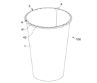
- FIG. 1 is a perspective view showing the appearance of a paper cup according to one embodiment of the present invention
- FIG. 2 is a diagram showing the front appearance of the paper cup.
- FIG. 2 is a plan view of the paper cup.
- FIG. 4 is an enlarged view of a portion F in FIG. 3 .
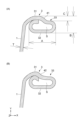
- 1A and 1B are enlarged views of a portion E in FIG. 1, and are cross-sectional views taken along lines AA and BB in FIG.
- FIG. 11 is a diagram showing experimental results of the openability of the flange portion of the above paper cup in comparison with a comparative example.
- FIG. 4 is a cross-sectional view showing the flange portion of the above paper cup in comparison with a comparative example. 4 is a flowchart showing a manufacturing process of the paper cup.
- FIG. 4 is a flowchart showing a manufacturing process of the paper cup.
- FIG. 11 is a perspective view showing the appearance of a paper cup according to a modified example of the present invention.
- FIG. 10 is a plan view of the paper cup of FIG.
- FIG. 11 is a perspective view showing the appearance of a paper cup according to another modified example of the present invention.
- FIG. 12 is a plan view of the paper cup of FIG. 11.
- FIG. 1 is a perspective view showing the appearance of a paper cup as a container according to one embodiment of the present invention.
- Fig. 2 is a diagram showing the front appearance of the paper cup, part of which is shown in cross section, and Fig. 3 is a plan view of the paper cup.
- the paper cup 100 has a body 1 and a bottom 2.
- the body 1 is made by coating (laminating) the raw paper material (base paper) with a thermoplastic resin such as polyethylene, polypropylene, or polyester, punching out a sector-shaped blank (body member), wrapping it around a cylindrical mold, and gluing the side ends together. By gluing the side ends together in this way, a side seam 4 is formed on the top and bottom of the side of the body 1.
- a thermoplastic resin such as polyethylene, polypropylene, or polyester
- the bottom 2 is made by drawing a circular bottom paper (bottom member) punched out from the same paper material as the body 1, and gluing it to the inside of the lower end of the body 1 at the same time as gluing the body 1.
- the bottom 2 may be made of a material other than paper, such as resin.
- the lower end of the body 1, to which the bottom 2 is attached, has the paper folded inward and pressed.
- the upper end of the body 1 has a flange 3 formed by folding one end of the body material outward, and the body 1 is open at this flange 3.
- a sealing material such as polyethylene film is heat sealed to the flange portion 3, sealing the paper cup 100.
- the paper material used as the raw material for the body 1 and bottom 2 is, for example, composed of multiple layers.
- the paper material may also be laminated with a synthetic resin layer, a foam layer, a metal layer, an inorganic vapor deposition film, etc.
- the body 1 and bottom 2 may be further laminated with a resin film such as polyethylene terephthalate.
- the flange portion 3 has a step portion 33, which has a protrusion 41 and a recess 42. These are described in detail below.
- the flange portion 3 has an overlapping portion 34 where two pieces of the body material are wrapped around the portion corresponding to the side seam portion 4, and an overlapping step portion 35 (the boundary between the overlapping portion 34 and a portion of one piece of the body material that does not overlap) formed on the side of the overlapping portion 34 in the circumferential direction of the body portion 1.
- FIG. 4 is an enlarged view of a portion F in Fig. 3.
- Fig. 5 is an enlarged view of a portion E in Fig. 2, which is a cross-sectional view taken along line AA in Fig. 4 (Fig. 4A) and a cross-sectional view taken along line BB in Fig. 4 (Fig. 4B).
- the flange portion 3 has a sealing surface 31 to which the sealing material is adhered, a curled portion 32 into which the body portion 1 is rolled, and a step portion 33.
- the width (length in the X direction) A of the flange portion 3 is greater than the height (thickness: length in the Y direction) B of the flange portion 3.
- the flange portion 3 of this embodiment has a shape that is flattened in the height direction (Y direction).
- the width A of the flange portion 3 is, for example, 2 to 5 mm, and the thickness B of the flange portion 3 is approximately 1 to 1.5 mm, which is at least four times the thickness T of the paper material (for example, 0.3 mm).
- a space S is formed inside the curled portion 32.
- the space S is secured to be equal to or larger than the thickness T of the paper material in the Y direction (approximately 1.5 times the thickness T in the example shown in the figure).
- the step portion 33 is formed on the outer peripheral edge of the upper surface of the flange portion 3. As will be described later, the step portion 33 is formed by press molding the outer peripheral edge of the curled flange portion.
- the seal head does not come into contact with the step 33 but only comes into contact with the inside of the flange 3 (seal surface 31) (or if it does come into contact, it is only weak contact), which prevents deformation of the outer diameter of the opening of the flange 3.
- the point of action of the opening force relative to the fulcrum is more inward than the outer circumferential edge of the flange 3 (the starting point of the step 33), so the moment of force is smaller, which is effective in making it easier to open (easy peel).
- pressing the curl can be performed to suppress deformation of the seal head and the flange 3 when opening the sealant.
- multiple protrusions 41 are formed in the circumferential direction of the step portion 33, protruding from the side surface of the step portion 33 outward in the radial direction of the body portion 1, and adjacent protrusions 41 form recesses 42 between them.
- the protrusions 41 and recesses 42 are formed by press molding at the same time as the step portion 33.
- the convex portions 41 are provided at a predetermined pitch (approximately 7 mm in the example shown in the figure) in the circumferential direction.
- the pitch is designed (less than approximately 9.5 mm) (less than 12°) so that one or more convex portions 41 are included in the bonding width (approximately 9.5 mm) of the overlapping portion 34 (side seam portion 4).
- the protrusion 41 shares its upper surface with the sealing surface 31, and is sealed together with the sealing surface 31 when the sealing material is sealed.
- the protruding width H of the convex portion 41 shown in FIG. 4 is, for example, equal to or greater than the thickness T of the paper material (for example, 1.2 to 1.7 mm).
- the larger the protruding width H the easier it is for the molten resin to flow into the concave portion, making it even more difficult for resin to accumulate in the step of the convex portion, improving ease of opening.
- a minimum protruding width for improving openability can be ensured.
- the convex portion 41 can be formed more clearly (at an acute angle), improving the openability of the seal material.
- [Easy opening of flange] 6 is a diagram showing the results of an experiment on the openability of the flange portion 3 of the paper cup 100 in comparison with a comparative example.
- a flange portion similar to the flange portion 3 of the present embodiment was used except that it did not have the protrusion 41.
- the overlapping portion 34 (side seam portion 4) was positioned at 0 o'clock in the circumferential direction, and sealing tabs were provided at four positions shifted by 45 degrees from there: 3 o'clock, 6 o'clock, and 9 o'clock.
- the sealing material was sealed under appropriate sealing conditions, and the opening strength when opened was measured.
- the opening strength at the overlapping portion (side seam portion) (0 o'clock) where the sealing load is applied is always stronger than the opening strength at the other three locations (3 o'clock, 6 o'clock, 9 o'clock).
- the opening strength at the overlapping portion 34 was not stronger than the other three locations, and the overall average showed a low opening strength.
- Figure 7 is a cross-sectional view showing the flange portion 3 in comparison with two comparative examples A and B.
- Comparative example A in the figure does not have the convex portion 41 and concave portion 42 like the flange portion 3 of this embodiment, and although a step portion and an internal space are formed, the height of the flange portion is smaller than the step portion 33 of this embodiment.
- Comparative example B in the figure is a flange in which the curled portion of the flange has been crushed (so-called flange press processing) so that no space is created, and it does not have any steps or convex or concave portions.
- flange 3 of this embodiment had the highest sealing strength, followed by comparative example A, and then comparative example B had the lowest sealing strength.
- the flange portion 3 in this embodiment uses a mold with a convex portion with a larger convex surface area than the convex portion of the mold used in Comparative Example A in order to press the step portion 33 and the convex portion 41 and concave portion 42, which increases the area of the bottom surface of the step portion 33 and increases the amount of paper that escapes from the step portion 33 to the convex portion 41 and concave portion 42 side.
- the seal head can be applied more firmly to the step portion 33 (and the protrusion 41) because the strength is increased due to the large number of bends in the flange portion 3 (the protrusion 41 and the recess 42), making it less likely for springback (the flange step returning) to occur when pressed by the seal head.
- the large height C of the step portion 33 not only improves the sealing strength, but also makes the boundary between the convex portion 41 and the concave portion 42 clearer, making it less likely for resin to accumulate in the convex portion 41, and therefore improving the ease of opening compared to the above comparative example A.
- Fig. 8 is a flow chart showing the flow of the manufacturing process for the paper cup 100.
- a fan-shaped blank is punched out from the paper material laminated with the thermoplastic resin, and both ends of the blank are melted with a gas burner or the like and then wrapped around a cylindrical mold and glued together to form the body 1 (step 61).
- a circular bottom paper punched out from the same paper material as above is drawn and vacuum-adsorbed to the cylindrical mold.
- the ends of the body 1 are bonded to each other and at the same time, the bottom 2 is bonded to the inside of the body 1.
- the bottom end of the body 1 is then folded toward the bottom 2 and crimped, thereby joining the bottom 2 to the body 1 (step 62).
- the upper end of the body 1 is curled outward while being rotated by a tool through a curling process, forming a flange portion (round curl) whose cross section in the radial direction (X direction) of the body 1 is circular (step 63).
- the upper end of the body 1 is molten in the circumferential direction using hot air, a gas burner, ultrasonic waves, or the like, and the adjacent pieces of paper material inside the curled portion 32 are bonded together.
- the formation of this adhesive also creates a space S inside the curled portion 32.
- the circular cross-sectional flange portion is pressed using a mold on which unevenness that conforms to the shapes of the step portion 33, and the protrusions 41 and recesses 42 are formed on the outer peripheral edge side, forming the step portion 33, the protrusions 41 and recesses 42, and forming the flange portion 3 that is flattened in the height direction (horizontally elongated in cross section) (step 64).
- the paper cup 100 is filled with ice, beverages, or other contents, and the sealant is adhered to the seal surface 31 of the flange portion 3 (and the upper surface of the protrusion 41) by heat sealing, thereby sealing the paper cup 100 (step 65).
- the convex portion 41 is sealed while the concave portion 42 is partially weakly sealed, improving the ease of opening as described above.
- an overlapping portion 34 where two body members overlap is formed in the portion corresponding to the side seam portion 4 of the flange portion 3, and an overlapping step portion 35 is formed at the boundary with the portion on the side where there is only one body member, so that a gap is generated in the overlapping step portion 35 when the sealant is heat sealed.
- the concave portion 42 is press molded to cross the overlapping step portion 35 of the flange portion 3, so that the gap in the overlapping step portion 35 is reduced.
- the concave portion 42 cross the overlapping step portion 35, when the sealant is heat sealed, the molten resin of the convex portion 41 flows into the concave portion 42, and the molten resin that has flowed in fills the gap, preventing leakage of the filled contents.
- the molten thermoplastic resin of the top seal material and flange portion 3 flows into the recess 42 of the flange portion 3, so that no resin pools are formed at the protrusion 41 (the step portion thereof), which is the starting point for opening and where stress is concentrated, and the sealing strength of the recess 42 is weakened, thereby improving the openability of the top seal material even under appropriate sealing conditions.
- the pitch of the convex portions 41 shown in the above-described embodiment can be changed as appropriate.
- the pitch of the convex portions 41 may be made smaller than that of the above-described embodiment.
- the pitch of the convex portions 41 is approximately 3.5 mm, half that of the above-described embodiment.
- the circumferential width of the concave portions 42 is also approximately half that of the above-described embodiment.
- the size and pitch of the convex portions 41 may be made larger than in the above-described embodiment.
- the pitch of the convex portions 41 is about two-thirds that of the above-described embodiment, and the circumferential width of the convex portions 41 is about three times that of the above-described embodiment. This also makes the circumferential width of the concave portions 42 relatively smaller.
- the convex portion 41 and the concave portion 42 are formed on the entire circumferential surface of the step portion 33, but they may be formed on only a part of the step portion 33. In that case, the convex portion 41 and the concave portion 42 may be provided at least in the overlap portion 34 (side seam portion 4) for the reasons described above.
- a space S is formed in the flange portion 3, but as long as the step portion 33, the convex portion 41, and the concave portion 42 can be formed, the space S may not be formed and the flange portion 3 may be formed in a flatter shape.
- the shapes of the flange portion 3 and the step portion 33 are not limited to those shown in FIG. 2, and the shapes of the convex portion 41 and the concave portion 42 may be changed accordingly.
- the convex portion 41 is provided so as to protrude from the side surface of the step portion 33 radially outward of the body portion 1, and the concave portion 42 is formed as a portion of the side surface of the step portion 33 between adjacent convex portions 41.
- the convex portion 41 may be provided so as to protrude from the side surface of the step portion 33 as described above, while the concave portion 42 may be provided so as to recess from the side surface of the step portion 33 radially inward of the body portion 1.
- the side surface of the step portion 33 includes a portion where the convex portion 41 is formed, a portion where the concave portion 42 is formed, and a portion where neither the convex portion 41 nor the concave portion 42 is formed.
- the convex portions 41 and the concave portions 42 may be formed alternately.
- the body 1 and bottom 2 are manufactured as separate parts, and the bottom 2 is glued to the body 1 to produce the paper cup 100.
- a container such as a paper cup may also be manufactured by forming the body and bottom integrally from a single sheet of paper material, and even in this case the flange portion can be molded in the same manner as in the above-described embodiment.
- the paper cup 100 is formed by molding the body 1 having the side seam 4 and the bottom 2 from paper material that has been coated with thermoplastic resin in advance, and then connecting the two.
- the paper cup 100 may be formed by molding the body and bottom from paper material that is not coated with thermoplastic resin, joining the body (side seam) and the bottom with resin (adhesive) to form a paper container, and attaching a resin film to the inner surface of the paper container by vacuum and/or pressure molding.
- a paper cup 100 is shown as a container, but the use of the container is not limited to a cup, and it may be used to hold food such as sweets, for example.
Landscapes
- Engineering & Computer Science (AREA)
- Mechanical Engineering (AREA)
- Packages (AREA)
- Containers Having Bodies Formed In One Piece (AREA)
Priority Applications (4)
| Application Number | Priority Date | Filing Date | Title |
|---|---|---|---|
| EP24831304.1A EP4733211A1 (en) | 2023-06-26 | 2024-01-29 | Paper container and paper container manufacturing method |
| KR1020257042235A KR20260012776A (ko) | 2023-06-26 | 2024-01-29 | 종이 용기 및 종이 용기의 제조 방법 |
| JP2025529425A JPWO2025004423A1 (https=) | 2023-06-26 | 2024-01-29 | |
| CN202480041294.4A CN121399030A (zh) | 2023-06-26 | 2024-01-29 | 纸容器及纸容器制造方法 |
Applications Claiming Priority (2)
| Application Number | Priority Date | Filing Date | Title |
|---|---|---|---|
| JP2023104559 | 2023-06-26 | ||
| JP2023-104559 | 2023-06-26 |
Publications (1)
| Publication Number | Publication Date |
|---|---|
| WO2025004423A1 true WO2025004423A1 (ja) | 2025-01-02 |
Family
ID=93938426
Family Applications (1)
| Application Number | Title | Priority Date | Filing Date |
|---|---|---|---|
| PCT/JP2024/002572 Ceased WO2025004423A1 (ja) | 2023-06-26 | 2024-01-29 | 紙容器及び紙容器製造方法 |
Country Status (5)
| Country | Link |
|---|---|
| EP (1) | EP4733211A1 (https=) |
| JP (1) | JPWO2025004423A1 (https=) |
| KR (1) | KR20260012776A (https=) |
| CN (1) | CN121399030A (https=) |
| WO (1) | WO2025004423A1 (https=) |
Citations (5)
| Publication number | Priority date | Publication date | Assignee | Title |
|---|---|---|---|---|
| JPS5726315U (https=) * | 1980-07-23 | 1982-02-10 | ||
| JP2004042987A (ja) | 2002-07-15 | 2004-02-12 | Toppan Printing Co Ltd | 飲料用紙カップ及びその製造方法 |
| JP2006193212A (ja) * | 2005-01-12 | 2006-07-27 | Iisan Co Ltd | 易開封性の使い捨て容器 |
| JP2008507458A (ja) | 2004-07-26 | 2008-03-13 | ストラ エンソ オーワイジェイ | プラスチックで被覆した厚紙のカップにマウスロールを作る方法およびこの方法で作ったカップ |
| WO2016013254A1 (ja) * | 2014-07-24 | 2016-01-28 | 東罐興業株式会社 | 容器及び容器製造方法 |
-
2024
- 2024-01-29 JP JP2025529425A patent/JPWO2025004423A1/ja active Pending
- 2024-01-29 CN CN202480041294.4A patent/CN121399030A/zh active Pending
- 2024-01-29 KR KR1020257042235A patent/KR20260012776A/ko active Pending
- 2024-01-29 EP EP24831304.1A patent/EP4733211A1/en active Pending
- 2024-01-29 WO PCT/JP2024/002572 patent/WO2025004423A1/ja not_active Ceased
Patent Citations (5)
| Publication number | Priority date | Publication date | Assignee | Title |
|---|---|---|---|---|
| JPS5726315U (https=) * | 1980-07-23 | 1982-02-10 | ||
| JP2004042987A (ja) | 2002-07-15 | 2004-02-12 | Toppan Printing Co Ltd | 飲料用紙カップ及びその製造方法 |
| JP2008507458A (ja) | 2004-07-26 | 2008-03-13 | ストラ エンソ オーワイジェイ | プラスチックで被覆した厚紙のカップにマウスロールを作る方法およびこの方法で作ったカップ |
| JP2006193212A (ja) * | 2005-01-12 | 2006-07-27 | Iisan Co Ltd | 易開封性の使い捨て容器 |
| WO2016013254A1 (ja) * | 2014-07-24 | 2016-01-28 | 東罐興業株式会社 | 容器及び容器製造方法 |
Also Published As
| Publication number | Publication date |
|---|---|
| KR20260012776A (ko) | 2026-01-27 |
| EP4733211A1 (en) | 2026-04-29 |
| JPWO2025004423A1 (https=) | 2025-01-02 |
| CN121399030A (zh) | 2026-01-23 |
Similar Documents
| Publication | Publication Date | Title |
|---|---|---|
| US4550854A (en) | Deep-drawn conical plastic container and method of making | |
| US12397963B2 (en) | Container assembly having a heat-sealed metal end, a metal end therefor, and a method for making same | |
| AU2012368754B2 (en) | Manufacturing method for manufacturing packaging container using funnel component | |
| WO2007054318A1 (en) | Insulated cup | |
| US20130256394A1 (en) | Paper Cup | |
| JP6315728B2 (ja) | 容器及び容器製造方法 | |
| WO2015145601A1 (ja) | 複合容器および複合容器の積み重ね構造 | |
| WO2025004423A1 (ja) | 紙容器及び紙容器製造方法 | |
| SE544726C2 (en) | An expansible press plunger, an attachment unit for attaching a container element to a container body and a method for sealing a packaging container | |
| JP7735532B2 (ja) | 容器及び容器製造方法 | |
| WO2024247362A1 (ja) | 容器及び容器製造方法 | |
| JP4478287B2 (ja) | コップ状容器 | |
| JPH0236458B2 (https=) | ||
| JP3462411B2 (ja) | カール部を有する容器 | |
| JPWO2024247362A5 (https=) | ||
| JP2607490Y2 (ja) | 紙製容器 | |
| JP5515441B2 (ja) | 紙製容器 | |
| JPS6229283B2 (https=) | ||
| JP2010254330A (ja) | 紙製容器 | |
| JP2010254329A (ja) | 紙製容器及びその製造方法 |
Legal Events
| Date | Code | Title | Description |
|---|---|---|---|
| 121 | Ep: the epo has been informed by wipo that ep was designated in this application |
Ref document number: 24831304 Country of ref document: EP Kind code of ref document: A1 |
|
| WWE | Wipo information: entry into national phase |
Ref document number: 2025529425 Country of ref document: JP |
|
| WWE | Wipo information: entry into national phase |
Ref document number: 2501008634 Country of ref document: TH |
|
| ENP | Entry into the national phase |
Ref document number: 1020257042235 Country of ref document: KR Free format text: ST27 STATUS EVENT CODE: A-0-1-A10-A15-NAP-PA0105 (AS PROVIDED BY THE NATIONAL OFFICE) |
|
| WWE | Wipo information: entry into national phase |
Ref document number: KR1020257042235 Country of ref document: KR Ref document number: 1020257042235 Country of ref document: KR |
|
| ENP | Entry into the national phase |
Ref document number: 2024831304 Country of ref document: EP Effective date: 20260126 |
|
| WWE | Wipo information: entry into national phase |
Ref document number: 2024831304 Country of ref document: EP |
|
| NENP | Non-entry into the national phase |
Ref country code: DE |
|
| WWP | Wipo information: published in national office |
Ref document number: 1020257042235 Country of ref document: KR |
|
| ENP | Entry into the national phase |
Ref document number: 2024831304 Country of ref document: EP Effective date: 20260126 |
|
| ENP | Entry into the national phase |
Ref document number: 2024831304 Country of ref document: EP Effective date: 20260126 |