WO2025004342A1 - ネットワークノード及び制御方法 - Google Patents
ネットワークノード及び制御方法 Download PDFInfo
- Publication number
- WO2025004342A1 WO2025004342A1 PCT/JP2023/024407 JP2023024407W WO2025004342A1 WO 2025004342 A1 WO2025004342 A1 WO 2025004342A1 JP 2023024407 W JP2023024407 W JP 2023024407W WO 2025004342 A1 WO2025004342 A1 WO 2025004342A1
- Authority
- WO
- WIPO (PCT)
- Prior art keywords
- service
- quality
- information
- access token
- network node
- Prior art date
- Legal status (The legal status is an assumption and is not a legal conclusion. Google has not performed a legal analysis and makes no representation as to the accuracy of the status listed.)
- Ceased
Links
Images





Classifications
-
- H—ELECTRICITY
- H04—ELECTRIC COMMUNICATION TECHNIQUE
- H04W—WIRELESS COMMUNICATION NETWORKS
- H04W88/00—Devices specially adapted for wireless communication networks, e.g. terminals, base stations or access point devices
- H04W88/18—Service support devices; Network management devices
-
- H—ELECTRICITY
- H04—ELECTRIC COMMUNICATION TECHNIQUE
- H04W—WIRELESS COMMUNICATION NETWORKS
- H04W92/00—Interfaces specially adapted for wireless communication networks
- H04W92/04—Interfaces between hierarchically different network devices
- H04W92/06—Interfaces between hierarchically different network devices between gateways and public network devices
Definitions
- the present invention relates to a network node and a control method in a communication system.
- 5G Fifth Generation Partnership Project
- 5G New Radio
- 5G 5G
- various wireless technologies are being studied to meet the requirements of achieving a throughput of 10 Gbps or more while keeping latency in wireless sections to 1 ms or less.
- NR is considering a network architecture including 5GC (5G Core Network), which corresponds to EPC (Evolved Packet Core), the core network in the network architecture of LTE (Long Term Evolution), and NG-RAN (Next Generation-Radio Access Network), which corresponds to E-UTRAN (Evolved Universal Terrestrial Radio Access Network), the RAN (Radio Access Network) in the network architecture of LTE (for example, non-patent document 1).
- 5GC 5G Core Network
- EPC Evolved Packet Core
- LTE Long Term Evolution
- NG-RAN Next Generation-Radio Access Network
- E-UTRAN Evolved Universal Terrestrial Radio Access Network
- the RAN Radio Access Network
- NEF Network Exposure Function
- AF Application Function
- CAPIF Common API Framework
- 3GPP TS 23.501 V18.1.0 (2023-03) 3GPP TS 29.522 V17.8.0 (2022-12) 3GPP TS 23.222 V18.0.0 (2022-12) 3GPP TS 23.502 V18.0.0 (2022-12)
- the 3GPP core network opens up APIs (Application Program Interfaces) to external applications, allowing third-party applications to call the APIs. Furthermore, CAPIF is being considered to allow resource owners to authorize API calls to the core network. Resource holders register in advance with an API exposing function or authorization function, and can access the resource holder from the API exposing function or authorization function when necessary to inquire whether the API can be called.
- APIs Application Program Interfaces
- CAPIF is being considered to allow resource owners to authorize API calls to the core network.
- Resource holders register in advance with an API exposing function or authorization function, and can access the resource holder from the API exposing function or authorization function when necessary to inquire whether the API can be called.
- an API invoker can request an API provider to change the Quality of Service (QoS) using an access token that indicates that the QoS upgrade is permitted.
- QoS Quality of Service
- the access token becomes invalid and the API invoker will no longer be able to change the QoS.
- the resource holder cannot change the QoS even if the access token is invalidated.
- the present invention has been made in consideration of the above points, and aims to restore changed resources when the resource holder revokes authorization for a resource change.
- a network node having a transmitter that transmits a first message requesting information on service quality, a receiver that receives the information on the service quality requested by the first message, and a controller that associates the information on the service quality with an access token corresponding to the information on the service quality and stores the associated information in a service quality list, in which the controller, upon receiving a notification on the access token, obtains the information on the service quality associated with the access token from the service quality list, the transmitter transmits a second message requesting restoration of the service quality associated with the access token, and the receiver receives a response to the second message.
- the disclosed technology allows the modified resources to be restored when the resource holder revokes authorization for a resource change.
- FIG. 1 is a diagram illustrating an example of a communication system.
- FIG. 1 is a diagram illustrating an example of a communication system in a roaming environment.
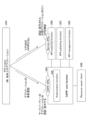
- FIG. 11 is a diagram for explaining an example of an API call.
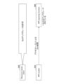
- FIG. 11 is a diagram for explaining an example (1) of QoS change.
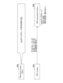
- FIG. 13 is a diagram for explaining an example (2) of QoS change.
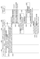
- 10A and 10B are diagrams for explaining an example of QoS change in an embodiment of the present invention.
- FIG. 11 is a sequence diagram illustrating an example of storing QoS information in the embodiment of the present invention.
- FIG. 4 is a diagram showing an example of a QoS information list in the embodiment of the present invention.
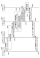
- FIG. 11 is a sequence diagram for explaining an example of QoS restoration in an embodiment of the present invention.
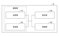
- FIG. 2 is a diagram illustrating an example of a functional configuration of a base station 10 and a network node 30 according to an embodiment of the present invention.
- FIG. 2 is a diagram illustrating an example of a functional configuration of a terminal 20 according to an embodiment of the present invention.
- 2 is a diagram illustrating an example of a hardware configuration of a base station 10 and a terminal 20 according to an embodiment of the present invention.
- FIG. 2 is a diagram showing an example of the configuration of a vehicle 2001 according to an embodiment of the present invention.
- LTE Long Term Evolution
- NR Universal Terrestrial Radio Access
- LAN Local Area Network
- “configuring" wireless parameters and the like may mean that predetermined values are pre-configured, or that wireless parameters notified from the network node 30 or the terminal 20 are configured.
- FIG. 1 is a diagram for explaining an example of a communication system.
- the communication system is composed of a UE, which is a terminal 20, and multiple network nodes 30.
- a UE which is a terminal 20
- multiple network nodes 30 In the following, it is assumed that one network node 30 corresponds to each function, but multiple functions may be realized by one network node 30, or multiple network nodes 30 may realize one function.
- the "connection" described below may be a logical connection or a physical connection.
- the RAN Radio Access Network
- the RAN is a network node 30 having a radio access function, which may include a base station 10, and is connected to a UE, an AMF (Access and Mobility Management Function), and a UPF (User plane function).
- the AMF is a network node 30 having functions such as RAN interface termination, NAS (Non-Access Stratum) termination, registration management, connection management, reachability management, and mobility management.
- the UPF is a network node 30 having functions such as a PDU (Protocol Data Unit) session point to the outside that interconnects with a DN (Data Network), packet routing and forwarding, and user plane QoS (Quality of Service) handling.
- the UPF and DN constitute a network slice. In the wireless communication network in an embodiment of the present invention, multiple network slices are constructed.
- the AMF is connected to the UE, RAN, SMF (Session Management function), NSSF (Network Slice Selection Function), NEF (Network Exposure Function), NRF (Network Repository Function), UDM (Unified Data Management), AUSF (Authentication Server Function), PCF (Policy Control Function), and AF (Application Function).
- the AMF, SMF, NSSF, NEF, NRF, UDM, AUSF, PCF, and AF are network nodes 30 that are interconnected via interfaces based on their respective services: Namf, Nsmf, Nnssf, Nnef, Nnrf, Nudm, Nausf, Npcf, and Naf.
- the SMF is a network node 30 having functions such as session management, IP (Internet Protocol) address allocation and management for UEs, DHCP (Dynamic Host Configuration Protocol) function, ARP (Address Resolution Protocol) proxy, and roaming function.
- the NEF is a network node 30 having a function of notifying other NFs (Network Functions) of capabilities and events.
- the NSSF is a network node 30 having functions such as selecting a network slice to which the UE connects, determining an allowed NSSAI (Network Slice Selection Assistance Information), determining an NSSAI to be set, and determining an AMF set to which the UE connects.
- the PCF is a network node 30 having a function of controlling network policies.
- the AF is a network node 30 having a function of controlling application servers.
- the NRF is a network node 30 having a function of discovering NF instances that provide services.
- the UDM is a network node 30 that manages subscriber data and authentication data.
- the UDM is connected to a User Data Repository (UDR) that holds the data.
- UDR User Data Repository
- FIG. 2 is a diagram for explaining an example of a communication system in a roaming environment.
- the network is composed of a UE, which is a terminal 20, and multiple network nodes 30.
- a UE which is a terminal 20
- multiple network nodes 30 it is assumed that one network node 30 corresponds to each function, but multiple functions may be realized by one network node 30, or multiple network nodes 30 may realize one function.
- the "connection" described below may be a logical connection or a physical connection.
- the RAN is a network node 30 with radio access functionality, and is connected to the UE, AMF, and UPF.
- the AMF is a network node 30 with functionality such as RAN interface termination, NAS termination, registration management, connection management, reachability management, and mobility management.
- the UPF is a network node 30 with functionality such as a PDU session point to the outside that interconnects with the DN, packet routing and forwarding, and user plane QoS handling.
- the UPF and DN constitute a network slice. In the wireless communication network in the embodiment of the present invention, multiple network slices are constructed.
- the AMF is connected to the UE, RAN, SMF, NSSF, NEF, NRF, UDM, AUSF, PCF, AF, and SEPP (Security Edge Protection Proxy).
- the AMF, SMF, NSSF, NEF, NRF, UDM, AUSF, PCF, and AF are network nodes 30 that are interconnected via interfaces based on their respective services: Namf, Nsmf, Nnssf, Nnef, Nnrf, Nudm, Nausf, Npcf, and Naf.
- the SMF is a network node 30 having functions such as session management, UE IP address allocation and management, DHCP function, ARP proxy, and roaming function.
- the NEF is a network node 30 having a function of notifying other NFs of capabilities and events.
- the NSSF is a network node 30 having functions such as selecting a network slice to which a UE will connect, determining an allowed NSSAI, determining an NSSAI to be configured, and determining an AMF set to which a UE will connect.
- the PCF is a network node 30 having a function of performing network policy control.
- the AF is a network node 30 having a function of controlling application servers.
- the NRF is a network node 30 having a function of discovering NF instances that provide services.
- the SEPP is a non-transparent proxy that filters control plane messages between PLMNs (Public Land Mobile Networks).
- the vSEPP shown in Figure 2 is a SEPP in the visited network
- the UE is in a roaming environment connected to the RAN and AMF in the VPLMN (Visited PLMN).
- the VPLMN and the HPLMN (Home PLMN) are connected via vSEPP and hSEPP.
- the UE can communicate with the UDM of the HPLMN, for example, via the AMF of the VPLMN.
- the 3GPP core network opens up APIs (Application Program Interfaces) to external applications, allowing third-party applications to call the APIs.
- APIs Application Program Interfaces
- FIG 3 is a diagram for explaining an example of an API call.
- an authorization function 30E in a CAPIF core function 30A receives pre-registration of an application sent from an API invoker 20A, and authenticates and authorizes the third-party application.
- An API exposing function 30B receives an API call of the core network sent from the API invoker, and opens the API to authenticated and authorized external applications.
- the authorization function 30E may be external to the CAPIF core function 30A.
- the resource owner client 20B can authorize an API call made by the core network via the CAPIF core function 30A and the authorization function 30E.
- the API providing function 30B can also access the authorization function 30E to check whether or not an API call can be made.
- the API caller 20A may be, for example, an application on a terminal or on a network node such as an application server, and may have the ability to support authentication by providing an identifier for the API caller, the ability to support mutual authentication with the CAPIF core function 30A, the ability to obtain authentication when accessing a service API, the ability to discover information related to the service API, and the ability to call the service API.
- the CAPIF core function 30A may have, for example, the ability to support mutual authentication with the API caller 20A, the ability to authenticate the API caller 20A when accessing a service API, the ability to publish and store information related to the service API, the ability to control access to the service API based on a policy set by the PLMN operator, the ability to record a service API call log and provide the service API call log to an approval authority, the ability to bill based on the service API call log, the ability to monitor service API calls, the ability to add and remove API callers 20A, the ability to support access to logs for auditing to detect unauthorized use, and the ability to publish information related to the service API together with other CAPIF core functions through connections between CAPIFs.
- the API providing function 30B is a provider that provides a service API, and may have the ability to authenticate the API caller 20A based on information provided by the CAPIF core function 30A, the ability to verify the authentication provided by the CAPIF core function 30A, and the ability to record a log of the service API call in the CAPIF core function 30A.
- the API publishing function 30C may have the ability to publish information related to the service APIs owned by the API provider to the CAPIF core function 30A.
- the API management function 30D is a function that allows the API provider to manage the service API, and may have the ability to audit the service API call log received from the CAPIF core function 30A, the ability to monitor events reported from the CAPIF core function 30A, the ability to set the policy of the API provider in the CAPIF core function 30A, the ability to monitor the status of the service API, the ability to add and delete API callers 20A, and the ability to register and maintain the registration information of the API provider in the CAPIF core function 30A.
- the API providing function 30B, the API publishing function 30C, and the API management function 30D may be functions or nodes belonging to one API provider.
- the CAPIF core function 30A, the API providing function 30B, the API publishing function 30C, and the API management function 30D may each be configured as a network node 30, or, for example, the API providing function 30B, the API publishing function 30C, and the API management function 30D may be configured as one network node 30.
- the API caller 20A, the resource holder client 20B, and the authorization function 30E may be, for example, a communication device such as a terminal or a server, or may be another communication device.
- the resource holder client 20B can authorize an API call of the core network using RNAA (Resource owner-aware northbound API access).
- Figure 4 is a diagram for explaining an example (1) of a QoS change.
- the resource owner client 20B allows the upgrade of the Quality of Service (QoS).
- the API invoker 20A requests the API exposing function 30B to change the QoS using an access token indicating that the QoS upgrade is permitted.
- FIG. 5 is a diagram for explaining an example (2) of a QoS change.
- the resource owner client 20B wants to stop the QoS upgrade, it can revoke the permission for the upgrade.
- the access token indicating that the upgrade is permitted becomes invalid, and the API caller 20A will no longer be able to change the QoS.
- the resource owner client 20B can invalidate the access token, it cannot change the QoS (return the upgraded QoS to its previous state).
- Example 1 will be described as an embodiment of the present invention.
- an operation of restoring a changed resource e.g., QoS
- QoS may be called quality of service or quality of service.
- FIG. 6 is a diagram for explaining an example of QoS change in an embodiment of the present invention.
- a resource owner client 20B requests a CAPIF core function 30A to cancel a token.
- the CAPIF core function 30A notifies an API exposing function 30B that the token has expired.
- the API exposing function 30B transmits information about the QoS corresponding to the expired token, which was stored before the API was applied, to a network node 30F in the 3GPP core network, thereby restoring the changed QoS to the QoS before the API was applied.
- the network node 30F may be, for example, a PCF (Policy Control Function).
- FIG. 7 is a sequence diagram for explaining an example of saving QoS information in an embodiment of the present invention. The processing of each step in Figure 7 will be described below.
- Step S301 The resource owner client 20B allows the API invoker 20A to update (upgrade) the quality of service (QoS).
- the API invoker 20A requests the CAPIF core function 30A to authenticate and authorize the application related to the service, and to provide an access token.
- the authorization function 30E in the CAPIF core function 30A performs authentication and authorization of the application in response to the request.
- Step S302 The API caller 20A sends a message to the API providing function 30B requesting the call of the service API.
- the message includes the access token acquired in step S301 and information about the quality of service (QoS) to be updated (upgraded).
- QoS quality of service
- Step S303 In response to the request message received in step S302, the API providing function 30B sends a message to the network node 30F in the 3GPP core network requesting the acquisition of information regarding the current quality of service (QoS).
- QoS quality of service
- Step S304 In response to the request message received in step S303, the network node 30F transmits information regarding the current quality of service (QoS) to the API providing function 30B.
- the network node 30F is, for example, a PCF (Policy Control Function).
- the information regarding the quality of service (QoS) may also include, for example, a quality of service identifier (for example, 5QI (5G QoS Identifier), see non-patent document 1).
- Step S305 The API providing function 30B stores the information on the current quality of service (QoS) received in step S304 and the access token corresponding to the information on the quality of service in the QoS information list.
- FIG. 8 is a diagram showing an example of a QoS information list in an embodiment of the present invention. As shown in FIG. 8, the QoS information list has information on the access token and information on the QoS.
- the information on the access token includes a value such as a number or identifier for identifying the access token (e.g., #aaa), or a value obtained by processing the value of the access token by hashing or the like.
- the information on the QoS is, for example, information on normal quality of service (Normal QoS information) required for reconfiguring the QoS of the terminal's IP address or terminal's MAC address (UE (IP or MAC) address), the identifier of the application session context, QoS information, etc. (see Section 5.2.5.3.2 of Non-Patent Document 4). Let us return to FIG. 7 for an explanation.
- Normal QoS information information on normal quality of service
- UE IP or MAC address
- Step S308 The network node 30F sends a response to the request message received in step S306 to the API providing function 30B.
- Step S309 The API providing function 30B sends a token event subscription request to the CAPIF core function 30A to receive notifications of events related to the access token received in step S302.
- Step S310 The CAPIF core function 30A sends a response to the request received in step S309 to the API providing function 30B.
- Figure 9 is a sequence diagram for explaining an example of QoS restoration in an embodiment of the present invention. The processing of each step in Figure 9 will be explained below.
- Step S405 The API providing function 30B checks the QoS information list for information related to the QoS that corresponds to the access token included in the notification received in step S403 (information related to normal QoS).
- Step S406 The API providing function 30B sends a request message to the network node 30F to restore the updated (upgraded) QoS to the normal QoS.
- the message includes information that identifies the user or terminal and information about the normal QoS (Normal QoS information).
- Step S407 In response to the request message received in step S406, network node 30F executes a restoration process to restore the updated (upgraded) QoS to the normal QoS.
- Step S408 The network node 30F sends a response to the request message received in step S406 to the API providing function 30B.
- the response may include information indicating that the QoS restoration process was successful.
- Step S409 The API providing function 30B sends a response corresponding to the notification received in step S403 to the CAPIF core function 30A.
- the response may include information indicating that the requested token was successfully revoked and information indicating that the QoS restoration process was successful.
- Step S410 The CAPIF core function 30A sends a response to the request received in step S401 to the resource holder client 20B.
- the response may include information indicating that the requested token was successfully revoked and information indicating that the QoS restoration process was successful.
- Modification A modified example will be described as an embodiment of the present invention.
- information on a predetermined quality of service is used. That is, the API providing function 30B receives a message requesting updating of the access token and the quality of service corresponding to the access token, as shown in step S302 of FIG. 7. Furthermore, after receiving a notification regarding the expiration of the access token, the API providing function 30B transmits a message requesting restoration of the quality of service (QoS) associated with the access token to a predetermined quality of service (QoS) to the network node 30F, as shown in step S403 of FIG.
- the message may include information indicating updating to a predetermined quality of service, or updating to a predetermined quality of service may be preset or determined by a standard.
- the above-described embodiment makes it possible to restore the changed resource (e.g., QoS) when the user (resource holder) revokes authorization for a resource change (e.g., permission to upgrade QoS). That is, when the resource holder revokes authorization for a resource change, the changed resource can be restored. Even if the user (resource holder) revokes authorization and invalidates the token, the original resource state can be restored without relying on a third-party API invoker. This makes it possible to prevent high-quality QoS from being set against the user's intention after the user (resource holder) invalidates the token. That is, it is possible to prevent unintentional high usage fees from being charged due to the use of high-quality services.
- a resource change e.g., permission to upgrade QoS
- the base station 10, the network node 30, and the terminal 20 each include functions for performing the above-described embodiments. However, the base station 10, the network node 30, and the terminal 20 may each include only a part of the functions in the embodiments.
- the transmitting unit 110 has a function of generating a signal to be transmitted to the terminal 20 or another network node 30, and transmitting the signal by wire or wirelessly.
- the receiving unit 120 has a function of receiving various signals transmitted from the terminal 20 or another network node 30, and acquiring, for example, information of a higher layer from the received signal.
- a communication unit including the transmitting unit 110 and the receiving unit 120 may be configured.
- the control unit 140 performs processing related to setting the service API in the network, as described in the embodiment.
- the control unit 140 also performs processing related to communication with the terminal 20.
- the functional unit in the control unit 140 related to signal transmission may be included in the transmitting unit 110, and the functional unit in the control unit 140 related to signal reception may be included in the receiving unit 120.
- Fig. 11 is a diagram showing an example of the functional configuration of the terminal 20.
- the terminal 20 has a transmitting unit 210, a receiving unit 220, a setting unit 230, and a control unit 240.
- the functional configuration shown in Fig. 11 is merely an example. As long as the operation related to the embodiment of the present invention can be performed, the names of the functional divisions and functional units may be any.
- the communication device that becomes the resource holder 20 may have the same functional configuration as the terminal 20.
- the transmitting unit 210 creates a transmission signal from the transmission data and transmits the transmission signal wirelessly.
- the receiving unit 220 receives various signals wirelessly and obtains higher layer signals from the received physical layer signals.
- the receiving unit 220 also has a function of receiving NR-PSS, NR-SSS, NR-PBCH, DL/UL control signals, reference signals, etc. transmitted from the network node 30.
- a communication unit including the transmitting unit 210 and the receiving unit 220 may be configured.
- the setting unit 230 stores various setting information received from the network node 30 by the receiving unit 220 in a storage device, and reads it out from the storage device as necessary.
- the setting unit 230 also stores setting information that is set in advance.
- the content of the setting information is, for example, information related to the service API in the network.
- the control unit 240 performs processing related to setting the service API in the network, as described in the embodiment.
- the functional unit related to signal transmission in the control unit 240 may be included in the transmitting unit 210, and the functional unit related to signal reception in the control unit 240 may be included in the receiving unit 220.
- each functional block may be realized using one device that is physically or logically coupled, or may be realized using two or more devices that are physically or logically separated and directly or indirectly connected (for example, using wires, wirelessly, etc.).
- the functional block may be realized by combining the one device or the multiple devices with software.
- Functions include, but are not limited to, judgement, determination, judgment, calculation, computation, processing, derivation, investigation, search, confirmation, reception, transmission, output, access, resolution, selection, election, establishment, comparison, assumption, expectation, regarding, broadcasting, notifying, communicating, forwarding, configuring, reconfiguring, allocating, mapping, and assignment.
- a functional block (component) that performs the transmission function is called a transmitting unit or transmitter.
- the network node 30, terminal 20, etc. in one embodiment of the present disclosure may function as a computer that performs processing of the wireless communication method of the present disclosure.
- FIG. 12 is a diagram showing an example of the hardware configuration of the base station 10 and terminal 20 in one embodiment of the present disclosure.
- the network node 30 may have the same hardware configuration as the base station 10.
- the above-mentioned base station 10 and terminal 20 may be physically configured as a computer device including a processor 1001, a memory device 1002, an auxiliary memory device 1003, a communication device 1004, an input device 1005, an output device 1006, a bus 1007, etc.
- the term "apparatus" can be interpreted as a circuit, device, unit, etc.
- the hardware configuration of the base station 10 and the terminal 20 may be configured to include one or more of the devices shown in the figure, or may be configured to exclude some of the devices.
- the functions of the base station 10 and the terminal 20 are realized by loading specific software (programs) onto hardware such as the processor 1001 and the storage device 1002, causing the processor 1001 to perform calculations, control communications by the communication device 1004, and control at least one of the reading and writing of data in the storage device 1002 and the auxiliary storage device 1003.
- the processor 1001 for example, operates an operating system to control the entire computer.
- the processor 1001 may be configured as a central processing unit (CPU) including an interface with peripheral devices, a control device, an arithmetic unit, registers, etc.
- CPU central processing unit
- control unit 140, control unit 240, etc. may be realized by the processor 1001.
- the processor 1001 reads out a program (program code), software module, data, etc. from at least one of the auxiliary storage device 1003 and the communication device 1004 to the storage device 1002, and executes various processes according to the program.
- the program is a program that causes a computer to execute at least a part of the operations described in the above-mentioned embodiment.
- the control unit 140 of the base station 10 shown in FIG. 10 may be stored in the storage device 1002 and realized by a control program that runs on the processor 1001.
- the control unit 240 of the terminal 20 shown in FIG. 11 may be stored in the storage device 1002 and realized by a control program that runs on the processor 1001.
- the processor 1001 may be implemented by one or more chips.
- the program may be transmitted from a network via a telecommunication line.
- the storage device 1002 is a computer-readable recording medium and may be composed of, for example, at least one of a ROM (Read Only Memory), an EPROM (Erasable Programmable ROM), an EEPROM (Electrically Erasable Programmable ROM), a RAM (Random Access Memory), etc.
- the storage device 1002 may also be called a register, a cache, a main memory, etc.
- the storage device 1002 can store executable programs (program codes), software modules, etc. for implementing a communication method relating to one embodiment of the present disclosure.
- the auxiliary storage device 1003 is a computer-readable recording medium, and may be, for example, at least one of an optical disk such as a CD-ROM (Compact Disc ROM), a hard disk drive, a flexible disk, a magneto-optical disk (e.g., a compact disk, a digital versatile disk, a Blu-ray (registered trademark) disk), a smart card, a flash memory (e.g., a card, a stick, a key drive), a floppy (registered trademark) disk, a magnetic strip, etc.
- the above-mentioned storage medium may be, for example, a database, a server, or other suitable medium that includes at least one of the storage device 1002 and the auxiliary storage device 1003.
- the communication device 1004 is hardware (transmitting/receiving device) for communicating between computers via at least one of a wired network and a wireless network, and is also referred to as, for example, a network device, a network controller, a network card, a communication module, etc.
- the communication device 1004 may be configured to include a high-frequency switch, a duplexer, a filter, a frequency synthesizer, etc., to realize at least one of, for example, Frequency Division Duplex (FDD) and Time Division Duplex (TDD).
- FDD Frequency Division Duplex
- TDD Time Division Duplex
- the transmitting/receiving antenna, an amplifier unit, a transmitting/receiving unit, a transmission path interface, etc. may be realized by the communication device 1004.
- the transmitting/receiving unit may be implemented as a transmitting unit or a receiving unit that is physically or logically separated.
- the input device 1005 is an input device (e.g., a keyboard, a mouse, a microphone, a switch, a button, a sensor, etc.) that accepts input from the outside.
- the output device 1006 is an output device (e.g., a display, a speaker, an LED lamp, etc.) that performs output to the outside. Note that the input device 1005 and the output device 1006 may be integrated into one structure (e.g., a touch panel).
- each device such as the processor 1001 and the storage device 1002 is connected by a bus 1007 for communicating information.
- the bus 1007 may be configured using a single bus, or may be configured using different buses between each device.
- the base station 10 and the terminal 20 may be configured to include hardware such as a microprocessor, a digital signal processor (DSP), an application specific integrated circuit (ASIC), a programmable logic device (PLD), or a field programmable gate array (FPGA), and some or all of the functional blocks may be realized by the hardware.
- the processor 1001 may be implemented using at least one of these pieces of hardware.
- FIG. 13 shows an example configuration of a vehicle 2001.
- the vehicle 2001 includes a drive unit 2002, a steering unit 2003, an accelerator pedal 2004, a brake pedal 2005, a shift lever 2006, front wheels 2007, rear wheels 2008, an axle 2009, an electronic control unit 2010, various sensors 2021-2029, an information service unit 2012, and a communication module 2013.
- a communication device mounted on the vehicle 2001 and may be applied to the communication module 2013, for example.
- the drive unit 2002 is composed of, for example, an engine, a motor, or a hybrid of an engine and a motor.
- the steering unit 2003 includes at least a steering wheel (also called a handlebar), and is configured to steer at least one of the front wheels and the rear wheels based on the operation of the steering wheel operated by the user.
- the electronic control unit 2010 is composed of a microprocessor 2031, memory (ROM, RAM) 2032, and a communication port (IO port) 2033. Signals are input to the electronic control unit 2010 from various sensors 2021 to 2029 provided in the vehicle 2001.
- the electronic control unit 2010 may also be called an ECU (Electronic Control Unit).
- Signals from the various sensors 2021-2029 include a current signal from a current sensor 2021 that senses the motor current, a front and rear wheel rotation speed signal obtained by a rotation speed sensor 2022, a front and rear wheel air pressure signal obtained by an air pressure sensor 2023, a vehicle speed signal obtained by a vehicle speed sensor 2024, an acceleration signal obtained by an acceleration sensor 2025, an accelerator pedal depression amount signal obtained by an accelerator pedal sensor 2029, a brake pedal depression amount signal obtained by a brake pedal sensor 2026, a shift lever operation signal obtained by a shift lever sensor 2027, and a detection signal for detecting obstacles, vehicles, pedestrians, etc. obtained by an object detection sensor 2028.
- the information service unit 2012 is composed of various devices, such as a car navigation system, an audio system, speakers, a television, and a radio, for providing (outputting) various information such as driving information, traffic information, and entertainment information, and one or more ECUs for controlling these devices.
- the information service unit 2012 uses information acquired from an external device via the communication module 2013 or the like to provide various multimedia information and multimedia services to the occupants of the vehicle 2001.
- the information service unit 2012 may include input devices (e.g., a keyboard, a mouse, a microphone, a switch, a button, a sensor, a touch panel, etc.) that accept input from the outside, and may also include output devices (e.g., a display, a speaker, an LED lamp, a touch panel, etc.) that perform output to the outside.
- input devices e.g., a keyboard, a mouse, a microphone, a switch, a button, a sensor, a touch panel, etc.
- output devices e.g., a display, a speaker, an LED lamp, a touch panel, etc.
- the driving assistance system unit 2030 is composed of various devices that provide functions for preventing accidents and reducing the driving burden on the driver, such as a millimeter wave radar, LiDAR (Light Detection and Ranging), a camera, a positioning locator (e.g., GNSS, etc.), map information (e.g., high definition (HD) maps, autonomous vehicle (AV) maps, etc.), a gyro system (e.g., IMU (Inertial Measurement Unit), INS (Inertial Navigation System), etc.), AI (Artificial Intelligence) chip, and AI processor, as well as one or more ECUs that control these devices.
- the driving assistance system unit 2030 transmits and receives various information via the communication module 2013 to realize driving assistance functions or autonomous driving functions.
- the communication module 2013 can communicate with the microprocessor 2031 and components of the vehicle 2001 via the communication port.
- the communication module 2013 transmits and receives data via the communication port 2033 between the drive unit 2002, steering unit 2003, accelerator pedal 2004, brake pedal 2005, shift lever 2006, front wheels 2007, rear wheels 2008, axle 2009, microprocessor 2031 and memory (ROM, RAM) 2032 in the electronic control unit 2010, and sensors 2021 to 29, which are provided in the vehicle 2001.
- the communication module 2013 is a communication device that can be controlled by the microprocessor 2031 of the electronic control unit 2010 and can communicate with an external device. For example, it transmits and receives various information to and from the external device via wireless communication.
- the communication module 2013 may be located either inside or outside the electronic control unit 2010.
- the external device may be, for example, a base station, a mobile station, etc.
- the communication module 2013 may transmit at least one of the signals from the various sensors 2021-2028 described above input to the electronic control unit 2010, information obtained based on the signals, and information based on input from the outside (user) obtained via the information service unit 2012 to an external device via wireless communication.
- the electronic control unit 2010, the various sensors 2021-2028, the information service unit 2012, etc. may be referred to as input units that accept input.
- the PUSCH transmitted by the communication module 2013 may include information based on the above input.
- the communication module 2013 receives various information (traffic information, signal information, vehicle distance information, etc.) transmitted from an external device, and displays it on the information service unit 2012 provided in the vehicle 2001.
- the information service unit 2012 may be called an output unit that outputs information (for example, outputs information to a device such as a display or speaker based on the PDSCH (or data/information decoded from the PDSCH) received by the communication module 2013).
- the communication module 2013 also stores various information received from an external device in a memory 2032 that can be used by the microprocessor 2031.
- the microprocessor 2031 may control the drive unit 2002, steering unit 2003, accelerator pedal 2004, brake pedal 2005, shift lever 2006, front wheels 2007, rear wheels 2008, axles 2009, sensors 2021 to 2029, etc. provided in the vehicle 2001.
- a network node having a transmitting unit that transmits a first message requesting information on service quality, a receiving unit that receives information on the service quality requested by the first message, and a control unit that associates the information on the service quality with an access token corresponding to the information on the service quality and stores them in a service quality list, wherein, upon receiving a notification regarding the access token, the control unit obtains the information on the service quality associated with the access token from the service quality list, the transmitting unit transmits a second message requesting restoration of the service quality associated with the access token, and the receiving unit receives a response to the second message.
- the service quality list may include at least one of the following information regarding the service quality: the IP address of the terminal, the MAC address of the terminal, an application session context identifier, and a service quality identifier.
- the notification may be a notification regarding the expiration of the access token.
- the transmission unit may transmit a response to the notification indicating that the restoration of the quality of service corresponding to the access token has been successful.
- a network node has a receiving unit that receives an access token and a first message requesting an update of the quality of service corresponding to the access token, and a transmitting unit that transmits a second message requesting that the quality of service associated with the access token be restored to a predetermined quality of service when a notification regarding the access token is received.
- the notification may be a notification regarding the expiration of the access token.
- the transmission unit may transmit a response to the notification indicating that the restoration of the quality of service corresponding to the access token has been successful.
- a control method executed by a network node having a transmission step of transmitting a first message requesting information on a quality of service, a reception step of receiving information on the quality of service requested by the first message, and a control step of associating the information on the quality of service with an access token corresponding to the information on the quality of service and storing the information on the quality of service in a quality of service list, the control step obtaining information on the quality of service associated with the access token from the quality of service list upon receiving a notification on the access token, the transmission step transmitting a second message requesting restoration of the quality of service associated with the access token, and the reception step receiving a response to the second message.
- the operations of multiple functional units may be physically performed by one part, or the operations of one functional unit may be physically performed by multiple parts.
- the order of the processing procedures described in the embodiment may be changed as long as there is no contradiction.
- the base station 10 and the terminal 20 have been described using functional block diagrams, but such devices may be realized by hardware, software, or a combination thereof.
- the software operated by the processor possessed by the base station 10 in accordance with an embodiment of the present invention and the software operated by the processor possessed by the terminal 20 in accordance with an embodiment of the present invention may each be stored in random access memory (RAM), flash memory, read only memory (ROM), EPROM, EEPROM, register, hard disk (HDD), removable disk, CD-ROM, database, server or any other suitable storage medium.
- the notification of information is not limited to the aspects/embodiments described in the present disclosure and may be performed using other methods.
- the notification of information may be performed by physical layer signaling (e.g., Downlink Control Information (DCI), Uplink Control Information (UCI)), higher layer signaling (e.g., Radio Resource Control (RRC) signaling, Medium Access Control (MAC) signaling), broadcast information (Master Information Block (MIB), System Information Block (SIB)), other signals, or a combination of these.
- RRC signaling may be referred to as an RRC message, and may be, for example, an RRC Connection Setup message, an RRC Connection Reconfiguration message, etc.
- Each aspect/embodiment described in this disclosure is a mobile communication system that is compatible with LTE (Long Term Evolution), LTE-A (LTE-Advanced), SUPER 3G, IMT-Advanced, 4G (4th generation mobile communication system), 5G (5th generation mobile communication system), 6th generation mobile communication system (6G), xth generation mobile communication system (xG) (xG (x is, for example, an integer or decimal number)), FRA (Future Ra).
- the present invention may be applied to at least one of systems using IEEE 802.11 (Wi-Fi (registered trademark)), IEEE 802.16 (WiMAX (registered trademark)), IEEE 802.20, UWB (Ultra-WideBand), Bluetooth (registered trademark), and other appropriate systems, and next-generation systems that are expanded, modified, created, or defined based on these. It may also be applied to a combination of multiple systems (for example, a combination of at least one of LTE and LTE-A with 5G, etc.).
- certain operations that are described as being performed by the base station 10 may in some cases be performed by its upper node.
- various operations performed for communication with a terminal 20 may be performed by at least one of the base station 10 and other network nodes other than the base station 10 (such as, but not limited to, an MME or S-GW).
- the base station 10 may be a combination of multiple other network nodes (such as an MME and an S-GW).
- the authorization function may be combined with a network node having functions other than authorization (e.g., an edge application server or edge enabler server having edge computing functions).
- a network node having functions other than authorization e.g., an edge application server or edge enabler server having edge computing functions.
- the information or signals described in this disclosure may be output from a higher layer (or a lower layer) to a lower layer (or a higher layer). They may be input and output via multiple network nodes.
- the input and output information may be stored in a specific location (e.g., memory) or may be managed using a management table.
- the input and output information may be overwritten, updated, or added to.
- the output information may be deleted.
- the input information may be sent to another device.
- the determination in this disclosure may be based on a value represented by one bit (0 or 1), a Boolean (true or false) value, or a comparison of numerical values (e.g., a comparison with a predetermined value).
- Software shall be construed broadly to mean instructions, instruction sets, code, code segments, program code, programs, subprograms, software modules, applications, software applications, software packages, routines, subroutines, objects, executable files, threads of execution, procedures, functions, etc., whether referred to as software, firmware, middleware, microcode, hardware description language, or otherwise.
- Software, instructions, information, etc. may also be transmitted and received via a transmission medium.
- a transmission medium For example, if the software is transmitted from a website, server, or other remote source using at least one of wired technologies (such as coaxial cable, fiber optic cable, twisted pair, Digital Subscriber Line (DSL)), and/or wireless technologies (such as infrared, microwave), then at least one of these wired and wireless technologies is included within the definition of a transmission medium.
- wired technologies such as coaxial cable, fiber optic cable, twisted pair, Digital Subscriber Line (DSL)
- wireless technologies such as infrared, microwave
- the information, signals, etc. described in this disclosure may be represented using any of a variety of different technologies.
- the data, instructions, commands, information, signals, bits, symbols, chips, etc. that may be referred to throughout the above description may be represented by voltages, currents, electromagnetic waves, magnetic fields or magnetic particles, optical fields or photons, or any combination thereof.
- At least one of the channel and the symbol may be a signal (signaling).
- the signal may be a message.
- a component carrier (CC) may be called a carrier frequency, a cell, a frequency carrier, etc.
- system and “network” are used interchangeably.
- radio resources may be indicated by an index.
- the names used for the above-mentioned parameters are not limiting in any respect. Furthermore, the formulas etc. using these parameters may differ from those explicitly disclosed in this disclosure.
- the various channels (e.g., PUCCH, PDCCH, etc.) and information elements may be identified by any suitable names, and therefore the various names assigned to these various channels and information elements are not limiting in any respect.
- base station BS
- wireless base station base station
- base station device fixed station
- NodeB nodeB
- eNodeB eNodeB
- gNodeB gNodeB
- access point e.g., "transmission point”
- gNodeB gNodeB
- a base station may also be referred to by terms such as macrocell, small cell, femtocell, and picocell.
- a base station can accommodate one or more (e.g., three) cells.
- a base station accommodates multiple cells, the entire coverage area of the base station can be divided into multiple smaller areas, and each smaller area can also provide communication services by a base station subsystem (e.g., a small indoor base station (RRH: Remote Radio Head)).
- RRH Remote Radio Head
- the term "cell” or “sector” refers to a part or the entire coverage area of at least one of the base station and base station subsystems that provide communication services in this coverage.
- a base station transmitting information to a terminal may be interpreted as the base station instructing the terminal to control or operate based on the information.
- MS Mobile Station
- UE User Equipment
- a mobile station may also be referred to by those skilled in the art as a subscriber station, mobile unit, subscriber unit, wireless unit, remote unit, mobile device, wireless device, wireless communication device, remote device, mobile subscriber station, access terminal, mobile terminal, wireless terminal, remote terminal, handset, user agent, mobile client, client, or some other suitable terminology.
- At least one of the base station and the mobile station may be called a transmitting device, a receiving device, a communication device, etc.
- At least one of the base station and the mobile station may be a device mounted on a moving object, the moving object itself, etc.
- the moving object is a movable object, and the moving speed is arbitrary. It also includes the case where the moving object is stopped.
- the moving object includes, but is not limited to, for example, a vehicle, a transport vehicle, an automobile, a motorcycle, a bicycle, a connected car, an excavator, a bulldozer, a wheel loader, a dump truck, a forklift, a train, a bus, a handcar, a rickshaw, a ship and other watercraft, an airplane, a rocket, an artificial satellite, a drone (registered trademark), a multicopter, a quadcopter, a balloon, and objects mounted thereon.
- the moving object may also be a moving object that travels autonomously based on an operation command.
- At least one of the base station and the mobile station may be a device that does not necessarily move during communication operations.
- at least one of the base station and the mobile station may be an IoT (Internet of Things) device such as a sensor.
- IoT Internet of Things
- the base station in the present disclosure may be read as a user terminal.
- each aspect/embodiment of the present disclosure may be applied to a configuration in which communication between a base station and a user terminal is replaced with communication between multiple terminals 20 (which may be called, for example, D2D (Device-to-Device) or V2X (Vehicle-to-Everything)).
- the terminal 20 may be configured to have the functions of the base station 10 described above.
- terms such as "uplink” and "downlink” may be read as terms corresponding to terminal-to-terminal communication (for example, "side").
- the uplink channel, downlink channel, etc. may be read as a side channel.
- the user terminal in this disclosure may be interpreted as a base station.
- the base station may be configured to have the functions of the user terminal described above.
- determining may encompass a wide variety of actions.
- Determining and “determining” may include, for example, judging, calculating, computing, processing, deriving, investigating, looking up, search, inquiry (e.g., searching in a table, database, or other data structure), and considering ascertaining as “judging” or “determining.”
- determining and “determining” may include receiving (e.g., receiving information), transmitting (e.g., sending information), input, output, accessing (e.g., accessing data in memory), and considering ascertaining as “judging” or “determining.”
- judgment” and “decision” can include considering resolving, selecting, choosing, establishing, comparing, etc., to have been “judged” or “decided.” In other words, “judgment” and “decision” can include considering some action to have been “judged” or “decided.” Additionally, “judgment (decision)” can be interpreted as “assuming,” “ex
- connection refers to any direct or indirect connection or coupling between two or more elements, and may include the presence of one or more intermediate elements between two elements that are “connected” or “coupled” to each other.
- the coupling or connection between elements may be physical, logical, or a combination thereof.
- “connected” may be read as "access.”
- two elements may be considered to be “connected” or “coupled” to each other using at least one of one or more wires, cables, and printed electrical connections, as well as electromagnetic energy having wavelengths in the radio frequency range, microwave range, and optical (both visible and invisible) range, as some non-limiting and non-exhaustive examples.
- the reference signal may also be abbreviated as RS (Reference Signal) or may be called a pilot depending on the applicable standard.
- any reference to an element using a designation such as "first,” “second,” etc., used in this disclosure does not generally limit the quantity or order of those elements. These designations may be used in this disclosure as a convenient method of distinguishing between two or more elements. Thus, a reference to a first and a second element does not imply that only two elements may be employed or that the first element must precede the second element in some way.
- a and B are different may mean “A and B are different from each other.”
- the term may also mean “A and B are each different from C.”
- Terms such as “separate” and “combined” may also be interpreted in the same way as “different.”
- notification of specific information is not limited to being done explicitly, but may be done implicitly (e.g., not notifying the specific information).
- Base station 110 Transmitter 120 Receiver 130 Setting unit 140 Control unit 20 Terminal 210 Transmitter 220 Receiver 230 Setting unit 240 Control unit 30 Network node 1001 Processor 1002 Storage device 1003 Auxiliary storage device 1004 Communication device 1005 Input device 1006 Output device
Landscapes
- Engineering & Computer Science (AREA)
- Computer Networks & Wireless Communication (AREA)
- Signal Processing (AREA)
- Mobile Radio Communication Systems (AREA)
Abstract
ネットワークノードは、サービス品質に関する情報を要求する第1メッセージを送信する送信部と、前記第1メッセージにより要求された前記サービス品質に関する情報を受信する受信部と、前記サービス品質に関する情報と、前記サービス品質に関する情報に対応するアクセストークンを関連付けて保存する制御部と、を有するネットワークノードであって、前記制御部は、前記アクセストークンに関する通知を受信した際に、前記アクセストークンに関連付けられた前記サービス品質に関する情報を取得し、前記送信部は、前記アクセストークンに関連付けられた前記サービス品質の復元を要求する第2メッセージを送信し、前記受信部は、前記第2メッセージに対する応答を受信する。
Description
本発明は、通信システムにおけるネットワークノード及び制御方法に関する。
3GPP(登録商標)(3rd Generation Partnership Project)では、システム容量の更なる大容量化、データ伝送速度の更なる高速化、無線区間における更なる低遅延化等を実現するために、5GあるいはNR(New Radio)と呼ばれる無線通信方式(以下、当該無線通信方式を「5G」あるいは「NR」という。)の検討が進んでいる。5Gでは、10Gbps以上のスループットを実現しつつ無線区間の遅延を1ms以下にするという要求条件を満たすために、様々な無線技術の検討が行われている。
NRでは、LTE(Long Term Evolution)のネットワークアーキテクチャにおけるコアネットワークであるEPC(Evolved Packet Core)に対応する5GC(5G Core Network)及びLTEのネットワークアーキテクチャにおけるRAN(Radio Access Network)であるE-UTRAN(Evolved Universal Terrestrial Radio Access Network)に対応するNG-RAN(Next Generation - Radio Access Network)を含むネットワークアーキテクチャが検討されている(例えば非特許文献1)。
また、例えば、5GシステムにおけるNEF(Network Exposure Function)とAF(Application Function)間のNorthboundインタフェースをCAPIF(Common API Framework)により構成するアーキテクチャが検討されている(例えば非特許文献2及び非特許文献3)。
3GPP TS 23.501 V18.1.0(2023-03)
3GPP TS 29.522 V17.8.0(2022-12)
3GPP TS 23.222 V18.0.0(2022-12)
3GPP TS 23.502 V18.0.0(2022-12)
3GPPコアネットワークでは、外部のアプリケーション向けにAPI(Application Program Interface)を開放しており、サードパーティのアプリケーションからAPIを呼び出すことができる。さらに、CAPIFにより、リソース保持者(resource owner)がコアネットワークのAPI呼び出しを認可することが検討されている。リソース保持者は事前にAPI提供機能(API exposing function)又は認可機能(authorization function)に登録(registration)しておき、必要なタイミングでAPI提供機能又は認可機能からリソース保持者にアクセスしてAPIの呼び出し可否を問い合わせることが可能となっている。
例えば、API呼び出し元(API invoker)が、QoS(Quality of Service)のアップグレード許可があることを示すアクセストークンにより、API提供機能にQoSの変更を要求することができる。QoSがアップグレードされた後、リソース保持者がQoSのアップグレード許可を取り消したい場合、当該アクセストークンは無効になり、API呼び出し元はQoSを変更できなくなる。また、リソース保持者は当該アクセストークンを無効化してもQoSを変更することはできない。
本発明は上記の点に鑑みてなされたものであり、リソース保持者がリソース変更に係る認可を取り消したとき、変更されたリソースを復旧することを目的とする。
開示の技術によれば、サービス品質に関する情報を要求する第1メッセージを送信する送信部と、前記第1メッセージにより要求された前記サービス品質に関する情報を受信する受信部と、前記サービス品質に関する情報と、前記サービス品質に関する情報に対応するアクセストークンを関連付けてサービス品質リストに保存する制御部と、を有するネットワークノードであって、前記制御部は、前記アクセストークンに関する通知を受信した際に、前記アクセストークンに関連付けられた前記サービス品質に関する情報を前記サービス品質リストから取得し、前記送信部は、前記アクセストークンに関連付けられた前記サービス品質の復元を要求する第2メッセージを送信し、前記受信部は、前記第2メッセージに対する応答を受信するネットワークノードが提供される。
開示の技術によれば、リソース保持者がリソース変更に係る認可を取り消したとき、変更されたリソースを復旧することができる。
以下、図面を参照して本発明の実施の形態を説明する。なお、以下で説明する実施の形態は一例であり、本発明が適用される実施の形態は、以下の実施の形態に限られない。
本発明の実施の形態の無線通信システムの動作にあたっては、適宜、既存技術が使用される。ただし、当該既存技術は、例えば既存のLTEであるが、既存のLTEに限られない。また、本明細書で使用する用語「LTE」は、特に断らない限り、LTE-Advanced、及び、LTE-Advanced以降の方式(例:NR)、又は無線LAN(Local Area Network)を含む広い意味を有するものとする。
また、本発明の実施の形態において、無線パラメータ等が「設定される(Configure)」とは、所定の値が予め設定(Pre-configure)されることであってもよいし、ネットワークノード30又は端末20から通知される無線パラメータが設定されることであってもよい。
図1は、通信システムの例を説明するための図である。図1に示されるように、通信システムは、端末20であるUE、複数のネットワークノード30から構成される。以下、機能ごとに1つのネットワークノード30が対応するものとするが、複数の機能を1つのネットワークノード30が実現してもよいし、複数のネットワークノード30が1つの機能を実現してもよい。また、以下に記載する「接続」は、論理的な接続であってもよいし、物理的な接続であってもよい。
RAN(Radio Access Network)は、無線アクセス機能を有するネットワークノード30であり、基地局10を含んでもよく、UE、AMF(Access and Mobility Management Function)及びUPF(User plane function)と接続される。AMFは、RANインタフェースの終端、NAS(Non-Access Stratum)の終端、登録管理、接続管理、到達性管理、モビリティ管理等の機能を有するネットワークノード30である。UPFは、DN(Data Network)と相互接続する外部に対するPDU(Protocol Data Unit)セッションポイント、パケットのルーティング及びフォワーディング、ユーザプレーンのQoS(Quality of Service)ハンドリング等の機能を有するネットワークノード30である。UPF及びDNは、ネットワークスライスを構成する。本発明の実施の形態における無線通信ネットワークでは、複数のネットワークスライスが構築されている。
AMFは、UE、RAN、SMF(Session Management function)、NSSF(Network Slice Selection Function)、NEF(Network Exposure Function)、NRF(Network Repository Function)、UDM(Unified Data Management)、AUSF(Authentication Server Function)、PCF(Policy Control Function)、AF(Application Function)と接続される。AMF、SMF、NSSF、NEF、NRF、UDM、AUSF、PCF、AFは、各々のサービスに基づくインタフェース、Namf、Nsmf、Nnssf、Nnef、Nnrf、Nudm、Nausf、Npcf、Nafを介して相互に接続されるネットワークノード30である。
SMFは、セッション管理、UEのIP(Internet Protocol)アドレス割り当て及び管理、DHCP(Dynamic Host Configuration Protocol)機能、ARP(Address Resolution Protocol)プロキシ、ローミング機能等の機能を有するネットワークノード30である。NEFは、他のNF(Network Function)に能力及びイベントを通知する機能を有するネットワークノード30である。NSSFは、UEが接続するネットワークスライスの選択、許可されるNSSAI(Network Slice Selection Assistance Information)の決定、設定されるNSSAIの決定、UEが接続するAMFセットの決定等の機能を有するネットワークノード30である。PCFは、ネットワークのポリシ制御を行う機能を有するネットワークノード30である。AFは、アプリケーションサーバを制御する機能を有するネットワークノード30である。NRFは、サービスを提供するNFインスタンスを発見する機能を有するネットワークノード30である。UDMは、加入者データ及び認証データを管理するネットワークノード30である。UDMは、当該データを保持するUDR(User Data Repository)と接続される。
図2は、ローミング環境下の通信システムの例を説明するための図である。図2に示されるように、ネットワークは、端末20であるUE、複数のネットワークノード30から構成される。以下、機能ごとに1つのネットワークノード30が対応するものとするが、複数の機能を1つのネットワークノード30が実現してもよいし、複数のネットワークノード30が1つの機能を実現してもよい。また、以下に記載する「接続」は、論理的な接続であってもよいし、物理的な接続であってもよい。
RANは、無線アクセス機能を有するネットワークノード30であり、UE、AMF及びUPFと接続される。AMFは、RANインタフェースの終端、NASの終端、登録管理、接続管理、到達性管理、モビリティ管理等の機能を有するネットワークノード30である。UPFは、DNと相互接続する外部に対するPDUセッションポイント、パケットのルーティング及びフォワーディング、ユーザプレーンのQoSハンドリング等の機能を有するネットワークノード30である。UPF及びDNは、ネットワークスライスを構成する。本発明の実施の形態における無線通信ネットワークでは、複数のネットワークスライスが構築されている。
AMFは、UE、RAN、SMF、NSSF、NEF、NRF、UDM、AUSF、PCF、AF、SEPP(Security Edge Protection Proxy)と接続される。AMF、SMF、NSSF、NEF、NRF、UDM、AUSF、PCF、AFは、各々のサービスに基づくインタフェース、Namf、Nsmf、Nnssf、Nnef、Nnrf、Nudm、Nausf、Npcf、Nafを介して相互に接続されるネットワークノード30である。
SMFは、セッション管理、UEのIPアドレス割り当て及び管理、DHCP機能、ARPプロキシ、ローミング機能等の機能を有するネットワークノード30である。NEFは、他のNFに能力及びイベントを通知する機能を有するネットワークノード30である。NSSFは、UEが接続するネットワークスライスの選択、許可されるNSSAIの決定、設定されるNSSAIの決定、UEが接続するAMFセットの決定等の機能を有するネットワークノード30である。PCFは、ネットワークのポリシ制御を行う機能を有するネットワークノード30である。AFは、アプリケーションサーバを制御する機能を有するネットワークノード30である。NRFは、サービスを提供するNFインスタンスを発見する機能を有するネットワークノード30である。SEPPは、非透過的なプロキシであり、PLMN(Public Land Mobile Network)間のコントロールプレーンのメッセージをフィルタリングする。図2に示されるvSEPPは、visitedネットワークにおけるSEPPであり、hSEPPは、homeネットワークにおけるSEPPである。
図2に示されるように、UEは、VPLMN(Visited PLMN)においてRAN及びAMFと接続されているローミング環境にある。VPLMN及びHPLMN(Home PLMN)は、vSEPP及びhSEPPを経由して接続されている。UEは、例えば、VPLMNのAMFを介してHPLMNのUDMと通信が可能である。
3GPPコアネットワークでは、外部のアプリケーション向けにAPI(Application Program Interface)を開放しており、サードパーティのアプリケーションからAPIを呼び出すことができる。
図3は、API呼び出しの例を説明するための図である。図3に示されるように、CAPIFコア機能30A(CAPIF core function)内の認可機能(Authorization function)30Eは、API呼び出し元20A(API invoker)から送信されるアプリケーションの事前登録を受信し、サードパーティのアプリケーションを認証及び許可する。API提供機能30B(API exposing function)は、API呼び出し元から送信されるコアネットワークのAPI呼び出しを受信し、認証及び認可された外部アプリケーション向けにAPIを開放する。なお、認可機能30Eは、CAPIFコア機能30Aの外部にあってもよい。
リソース保持者クライアント(Resource owner client)20Bは、CAPIFコア機能30A及び認可機能30Eを介して、コアネットワークによるAPI呼び出しを認可することが可能である。また、API提供機能30Bは、認可機能30EにアクセスしてAPIの呼び出し可否を確認することが可能である。
API呼び出し元20Aは、例えば、端末上またはアプリケーションサーバなどのネットワークノード上のアプリケーションであり、API呼び出し元の識別子を提供することにより認証をサポートする能力、CAPIFコア機能30Aとの相互認証をサポートする能力、サービスAPIにアクセスする際の認証を取得する能力、サービスAPIに係る情報を発見する能力、サービスAPIを呼び出す能力を有してもよい。
CAPIFコア機能30Aは、例えば、API呼び出し元20Aとの相互認証をサポートする能力、サービスAPIにアクセスする際にAPI呼び出し元20Aを認証する能力、サービスAPIに係る情報を公開及び蓄積する能力、PLMNオペレータが設定するポリシに基づいたサービスAPIのアクセス制御を行う能力、サービスAPIの呼び出しログの記録及び承認機関へのサービスAPIの呼び出しログの提供を行う能力、サービスAPIの呼び出しログに基づく課金を行う能力、サービスAPIの呼び出しをモニタリングする能力、API呼び出し元20Aの追加及び削除を行う能力、例えば不正使用を検出する監査のためのログへのアクセスをサポートする能力、CAPIF間の接続による他のCAPIFコア機能と共にサービスAPIに係る情報を公開する能力を有してもよい。
API提供機能30Bは、サービスAPIを提供するプロバイダであり、CAPIFコア機能30Aから提供された情報に基づいてAPI呼び出し元20Aを認証する能力、CAPIFコア機能30Aから提供された認証を検証する能力、CAPIFコア機能30AにおけるサービスAPI呼び出しのログを記録する能力を有してもよい。
API公開機能30C(API publishing function)は、CAPIFコア機能30Aに、当該APIプロバイダが有するサービスAPIに係る情報を公開する能力を有してもよい。
API管理機能30D(API management function)は、当該APIプロバイダにサービスAPIの管理を実行させる機能であり、CAPIFコア機能30Aから受信したサービスAPI呼び出しログを監査する能力、CAPIFコア機能30Aから報告されたイベントをモニタリングする能力、CAPIFコア機能30Aに当該APIプロバイダのポリシを設定する能力、サービスAPIの状態をモニタリングする能力、API呼び出し元20Aを追加及び削除する能力、当該APIプロバイダの登録情報をCAPIFコア機能30Aに登録及び維持する能力を有してもよい。
なお、API提供機能30B、API公開機能30C及びAPI管理機能30Dは、ある1つのAPIプロバイダに属する機能又はノードであってもよい。あるいは、CAPIFコア機能30A、API提供機能30B、API公開機能30C、及びAPI管理機能30Dは、それぞれネットワークノード30として構成されてもよいし、例えば、API提供機能30B、API公開機能30C及びAPI管理機能30Dが1つのネットワークノード30として構成されてもよい。また、API呼び出し元20A、リソース保持者クライアント20B及び認可機能30Eは、例えば、端末又はサーバ等の通信装置であってもよいし、その他の通信装置であってもよい。また、CAPIFを拡張して、RNAA(Resource owner-aware northbound API access)により、リソース保持者クライアント20B(Resource owner client)がコアネットワークのAPI呼び出しを認可することが可能である。
図4は、QoS変更の例(1)を説明するための図である。図4に示されるように、まず、リソース保持者クライアント20B(Resource owner client)は、QoS(Quality of Service)のアップグレードを許可する。次に、API呼び出し元20A(API invoker)は、QoSのアップグレードの許可があることを示すアクセストークンにより、API提供機能30B(API exposing function)にQoSの変更を要求する。
図5は、QoS変更の例(2)を説明するための図である。図5に示されるように、QoSがアップグレードされた後、リソース保持者クライアント20B(Resource owner client)は、QoSのアップグレードを停止したい場合、当該アップグレードの許可を取り消すことができる。このとき、当該アップグレードの許可があることを示すアクセストークンは無効になり、API呼び出し元20Aは、QoSを変更できなくなる。また、リソース保持者クライアント20Bは、当該アクセストークンを無効化することはできるが、QoSを変更すること(アップグレードされたQoSを前の状態に戻すこと)はできない。
(実施例1)
本発明の実施の形態として実施例1について説明する。実施例1では、リソース保持者がリソース変更に係る認可(例えば、QoSのアップグレード許可)を取り消したとき、変更されたリソース(例えば、QoS)を復旧する動作について説明する。ここで、QoSをサービス品質又はサービスの品質とよんでもよい。図6は、本発明の実施の形態におけるQoS変更の例を説明するための図である。図6に示されるように、リソース保持者クライアント20B(Resource owner client)は、トークンの取り消しをCAPIFコア機能30A(CAPIF core function)に要求する。CAPIFコア機能30Aは、トークンが失効したことをAPI提供機能30B(API exposing function)に通知する。API提供機能30Bは、API適用前に保存した、失効したトークンに対応するQoSに関する情報を3GPPコアネットワークにおけるネットワークノード30Fに送信することにより、変更されたQoSをAPI適用前のQoSに復旧する。ここで、ネットワークノード30Fは、例えば、PCF(Policy Control Function)であってもよい。
本発明の実施の形態として実施例1について説明する。実施例1では、リソース保持者がリソース変更に係る認可(例えば、QoSのアップグレード許可)を取り消したとき、変更されたリソース(例えば、QoS)を復旧する動作について説明する。ここで、QoSをサービス品質又はサービスの品質とよんでもよい。図6は、本発明の実施の形態におけるQoS変更の例を説明するための図である。図6に示されるように、リソース保持者クライアント20B(Resource owner client)は、トークンの取り消しをCAPIFコア機能30A(CAPIF core function)に要求する。CAPIFコア機能30Aは、トークンが失効したことをAPI提供機能30B(API exposing function)に通知する。API提供機能30Bは、API適用前に保存した、失効したトークンに対応するQoSに関する情報を3GPPコアネットワークにおけるネットワークノード30Fに送信することにより、変更されたQoSをAPI適用前のQoSに復旧する。ここで、ネットワークノード30Fは、例えば、PCF(Policy Control Function)であってもよい。
更に、実施例1における動作の詳細について説明する。まず、サービス品質(QoS)に関する情報を保存する動作について説明する。図7は、本発明の実施の形態におけるQoS情報の保存の例を説明するためのシーケンス図である。以下、図7の各ステップの処理について説明する。
ステップS301:リソース保持者クライアント20B(Resource owner client)は、API呼び出し元20A(API invoker)に対して、サービス品質(QoS)の更新(アップグレード)を許可する。API呼び出し元20Aは、CAPIFコア機能30A(CAPIF core function)に、当該サービスに関するアプリケーションの認証と認可、及びアクセストークンを要求する。CAPIFコア機能30A内の認可機能30E(Authorization function)は、要求に応じてアプリケーションの認証と認可を実行する。
ステップS302:API呼び出し元20Aは、API提供機能30Bに、サービスAPIの呼び出しを要求するメッセージを送信する。当該メッセージは、ステップS301で取得したアクセストークンと、更新(アップグレード)するサービス品質(QoS)に関する情報を含む。
ステップS303:API提供機能30Bは、ステップS302で受信した要求メッセージに応じて、現在のサービス品質(QoS)に関する情報の取得を要求するメッセージを3GPPコアネットワークにおけるネットワークノード30Fに送信する。
ステップS304:ネットワークノード30Fは、ステップS303で受信した要求メッセージに応じて、現在のサービス品質(QoS)に関する情報をAPI提供機能30Bに送信する。ここで、ネットワークノード30Fは、例えば、PCF(Policy Control Function)である。また、サービス品質(QoS)に関する情報は、例えば、サービス品質の識別子(例えば、5QI(5G QoS Identifier)、非特許文献1を参照可能)を含んでもよい。
ステップS305:API提供機能30Bは、ステップS304で受信した現在のサービス品質(QoS)に関する情報と、当該サービス品質の情報に対応するアクセストークンをQoS情報リストに保存する。図8は、本発明の実施の形態におけるQoS情報リストの一例を示す図である。図8に示すように、QoS情報リストは、アクセストークンに関する情報とQoSに関する情報を有する。アクセストークンに関する情報は、アクセストークンを特定するための番号又は識別子などの値(例えば、#aaa)、又は、アクセストークンの値をハッシュ化などにより加工した値を含む。QoSに関する情報は、例えば、端末のIPアドレス又は端末のMACアドレス(UE (IP or MAC) address)、アプリケーションセッションコンテキストの識別子(identification of the application session context)、QoS情報(QoS information)など(非特許文献4の5.2.5.3.2節を参照可能)のQoSの再設定に必要となる通常におけるサービス品質に関する情報(Normal QoS information)である。図7に戻って説明する。
ステップS306:API提供機能30Bは、ステップS302で受信した要求メッセージに応じて、ネットワークノード30Fに、QoSの更新を要求するメッセージを送信する。当該メッセージは、ユーザまたは端末を特定する情報と、更新(アップグレード)するサービス品質(QoS)に関する情報を含む。サービス品質(QoS)に関する情報は、サービス品質の識別子(5QIなど)を含んでもよい。ユーザを特定する情報は、例えば、SUPI(Subscription Permanent Identifier)である。端末を特定する情報は、例えば、端末のIPアドレス、又は端末のMACアドレスである。
ステップS307:ネットワークノード30Fは、ステップS306で受信した要求メッセージに応じて、QoSの更新処理を実行する。
ステップS308:ネットワークノード30Fは、API提供機能30Bに、ステップS306で受信した要求メッセージに対する応答を送信する。
ステップS309:API提供機能30Bは、CAPIFコア機能30Aに、ステップS302で受信したアクセストークンに関するイベントの通知を受信するためのトークンイベント購読要求を送信する。
ステップS310:CAPIFコア機能30Aは、API提供機能30Bに、ステップS309で受信した要求に対する応答を送信する。
続いて、QoS復元の動作について説明する。図9は、本発明の実施の形態におけるQoS復元の例を説明するためのシーケンス図である。以下、図9の各ステップの処理について説明する。
ステップS401:リソース保持者クライアント20Bは、CAPIFコア機能30Aに、図7のステップS301で取得したアクセストークンの取消を要求するメッセージを送信する。
ステップS402:CAPIFコア機能30Aは、受信した要求に応じて、トークンの取消を実行する。
ステップS403:CAPIFコア機能30Aは、API提供機能30Bに、図7のステップS301で取得したアクセストークンが取り消されて失効したことを示すトークンイベントの通知を送信する。当該通知は、失効したアクセストークンに関する情報を含む。
ステップS404:API提供機能30Bは、ステップS403で受信した通知に含まれるアクセストークンに関する情報が、図7のステップS305で保存したQoS情報リストに含まれることを確認することにより、QoSの復元の必要性を検出する。
ステップS405:API提供機能30Bは、QoS情報リストにおいて、ステップS403で受信した通知に含まれるアクセストークンに対応するQoSに関する情報(通常におけるQoSに関する情報)を調査する。
ステップS406:API提供機能30Bは、ネットワークノード30Fに、更新(アップグレード)されたQoSを通常のQoSに復元する要求メッセージを送信する。当該メッセージは、ユーザまたは端末を特定する情報と、通常におけるQoSに関する情報(Normal QoS information)を含む。
ステップS407:ネットワークノード30Fは、ステップS406で受信した要求メッセージに応じて、更新(アップグレード)されたQoSを通常におけるQoSに復元する復元処理を実行する。
ステップS408:ネットワークノード30Fは、API提供機能30Bに、ステップS406で受信した要求メッセージに対する応答を送信する。当該応答は、QoSの復元処理が成功したことを示す情報を含んでもよい。
ステップS409:API提供機能30Bは、CAPIFコア機能30Aに、ステップS403で受信した通知に対応する応答を送信する。当該応答は、要求されたトークンの取消が成功したことを示す情報、及びQoSの復元処理が成功したことを示す情報を含んでもよい。
ステップS410:CAPIFコア機能30Aは、リソース保持者クライアント20Bに、ステップS401で受信した要求に対する応答を送信する。当該応答は、要求されたトークンの取消が成功したことを示す情報、及びQoSの復元処理が成功したことを示す情報を含んでもよい。
(変形例)
本発明の実施の形態として変形例について説明する。変形例では、実施例1における図8に示したQoS情報リストに保存したサービス品質に関する情報を用いる代わりに、予め定められたサービス品質に関する情報を用いる。すなわち、API提供機能30Bは、図7のステップS302で示した様に、アクセストークンとアクセストークンに対応するサービス品質の更新を要求するメッセージを受信する。更に、API提供機能30Bは、図8のステップS403で示した様に、アクセストークンの失効に関する通知を受信した後、アクセストークンに関連付けられたサービス品質(QoS)を予め定められたサービス品質(QoS)に復元することを要求するメッセージをネットワークノード30Fに送信する。当該メッセージは、予め定められたサービス品質に更新することを示す情報を含んでもよいし、或いは、予め定められたサービス品質に更新することを予め設定しておく、又は、規格により定めてもよい。
本発明の実施の形態として変形例について説明する。変形例では、実施例1における図8に示したQoS情報リストに保存したサービス品質に関する情報を用いる代わりに、予め定められたサービス品質に関する情報を用いる。すなわち、API提供機能30Bは、図7のステップS302で示した様に、アクセストークンとアクセストークンに対応するサービス品質の更新を要求するメッセージを受信する。更に、API提供機能30Bは、図8のステップS403で示した様に、アクセストークンの失効に関する通知を受信した後、アクセストークンに関連付けられたサービス品質(QoS)を予め定められたサービス品質(QoS)に復元することを要求するメッセージをネットワークノード30Fに送信する。当該メッセージは、予め定められたサービス品質に更新することを示す情報を含んでもよいし、或いは、予め定められたサービス品質に更新することを予め設定しておく、又は、規格により定めてもよい。
上述の実施例により、ユーザ(リソース所持者)がリソース変更に係る認可(例えば、QoSのアップグレード許可)を取り消したとき、変更されたリソース(例えば、QoS)を復旧することが可能いである。すなわち、リソース保持者がリソース変更に係る認可を取り消したとき、変更されたリソースを復旧することが可能である。また、ユーザ(リソース所持者)が認可を取り消し、トークンを無効化した場合でも、第三者のAPI invokerに頼ることなく、もとのリソース状態に戻すことができる。これにより、ユーザ(リソース所持者)がトークンを無効化した後に、ユーザの意図に反して高品質のQoSが設定されてしまうことを避けることが可能である。すなわち、高品質なサービスの利用による、意図しない高額な使用料金の請求を防止することが可能である。
(装置構成)
次に、これまでに説明した処理及び動作を実施する基地局10、ネットワークノード30及び端末20の機能構成例を説明する。基地局10、ネットワークノード30及び端末20は上述した実施例を実施する機能を含む。ただし、基地局10、ネットワークノード30及び端末20はそれぞれ、実施例の中の一部の機能のみを備えることとしてもよい。
次に、これまでに説明した処理及び動作を実施する基地局10、ネットワークノード30及び端末20の機能構成例を説明する。基地局10、ネットワークノード30及び端末20は上述した実施例を実施する機能を含む。ただし、基地局10、ネットワークノード30及び端末20はそれぞれ、実施例の中の一部の機能のみを備えることとしてもよい。
<基地局10及びネットワークノード30>
図10は、基地局10及びネットワークノード30の機能構成の一例を示す図である。図10に示されるように、基地局10は、送信部110と、受信部120と、設定部130と、制御部140とを有する。図10に示される機能構成は一例に過ぎない。本発明の実施の形態に係る動作を実施できるのであれば、機能区分及び機能部の名称はどのようなものでもよい。なお、ネットワークノード30は、基地局10と同様の機能構成を有してもよい。また、システムアーキテクチャ上で複数の異なる機能を有するネットワークノード30は、機能ごとに分離された複数のネットワークノード30から構成されてもよい。
図10は、基地局10及びネットワークノード30の機能構成の一例を示す図である。図10に示されるように、基地局10は、送信部110と、受信部120と、設定部130と、制御部140とを有する。図10に示される機能構成は一例に過ぎない。本発明の実施の形態に係る動作を実施できるのであれば、機能区分及び機能部の名称はどのようなものでもよい。なお、ネットワークノード30は、基地局10と同様の機能構成を有してもよい。また、システムアーキテクチャ上で複数の異なる機能を有するネットワークノード30は、機能ごとに分離された複数のネットワークノード30から構成されてもよい。
送信部110は、端末20又は他のネットワークノード30に送信する信号を生成し、当該信号を有線又は無線で送信する機能を含む。受信部120は、端末20又は他のネットワークノード30から送信された各種の信号を受信し、受信した信号から、例えばより上位のレイヤの情報を取得する機能を含む。送信部110及び受信部120を含む通信部が構成されてもよい。
設定部130は、予め設定される設定情報、及び、端末20に送信する各種の設定情報を記憶装置に格納し、必要に応じて記憶装置から読み出す。設定情報の内容は、例えば、ネットワークにおけるサービスAPIに係る情報等である。
制御部140は、実施例において説明したように、ネットワークにおけるサービスAPIの設定に係る処理を行う。また、制御部140は、端末20との通信に係る処理を行う。制御部140における信号送信に関する機能部を送信部110に含め、制御部140における信号受信に関する機能部を受信部120に含めてもよい。
<端末20>
図11は、端末20の機能構成の一例を示す図である。図11に示されるように、端末20は、送信部210と、受信部220と、設定部230と、制御部240とを有する。図11に示される機能構成は一例に過ぎない。本発明の実施の形態に係る動作を実施できるのであれば、機能区分及び機能部の名称はどのようなものでもよい。また、リソース保持者20となる通信装置は、端末20と同様の機能構成を有してもよい。
図11は、端末20の機能構成の一例を示す図である。図11に示されるように、端末20は、送信部210と、受信部220と、設定部230と、制御部240とを有する。図11に示される機能構成は一例に過ぎない。本発明の実施の形態に係る動作を実施できるのであれば、機能区分及び機能部の名称はどのようなものでもよい。また、リソース保持者20となる通信装置は、端末20と同様の機能構成を有してもよい。
送信部210は、送信データから送信信号を作成し、当該送信信号を無線で送信する。受信部220は、各種の信号を無線受信し、受信した物理レイヤの信号からより上位のレイヤの信号を取得する。また、受信部220は、ネットワークノード30から送信されるNR-PSS、NR-SSS、NR-PBCH、DL/UL制御信号又は参照信号等を受信する機能を有する。送信部210及び受信部220を含む通信部が構成されてもよい。
設定部230は、受信部220によりネットワークノード30から受信した各種の設定情報を記憶装置に格納し、必要に応じて記憶装置から読み出す。また、設定部230は、予め設定される設定情報も格納する。設定情報の内容は、例えば、ネットワークにおけるサービスAPIに係る情報等である。
制御部240は、実施例において説明したように、ネットワークにおけるサービスAPIの設定に係る処理を行う。制御部240における信号送信に関する機能部を送信部210に含め、制御部240における信号受信に関する機能部を受信部220に含めてもよい。
(ハードウェア構成)
上記実施形態の説明に用いたブロック図(図10及び図11)は、機能単位のブロックを示している。これらの機能ブロック(構成部)は、ハードウェア及びソフトウェアの少なくとも一方の任意の組み合わせによって実現される。また、各機能ブロックの実現方法は特に限定されない。すなわち、各機能ブロックは、物理的又は論理的に結合した1つの装置を用いて実現されてもよいし、物理的又は論理的に分離した2つ以上の装置を直接的又は間接的に(例えば、有線、無線などを用いて)接続し、これら複数の装置を用いて実現されてもよい。機能ブロックは、上記1つの装置又は上記複数の装置にソフトウェアを組み合わせて実現されてもよい。
上記実施形態の説明に用いたブロック図(図10及び図11)は、機能単位のブロックを示している。これらの機能ブロック(構成部)は、ハードウェア及びソフトウェアの少なくとも一方の任意の組み合わせによって実現される。また、各機能ブロックの実現方法は特に限定されない。すなわち、各機能ブロックは、物理的又は論理的に結合した1つの装置を用いて実現されてもよいし、物理的又は論理的に分離した2つ以上の装置を直接的又は間接的に(例えば、有線、無線などを用いて)接続し、これら複数の装置を用いて実現されてもよい。機能ブロックは、上記1つの装置又は上記複数の装置にソフトウェアを組み合わせて実現されてもよい。
機能には、判断、決定、判定、計算、算出、処理、導出、調査、探索、確認、受信、送信、出力、アクセス、解決、選択、選定、確立、比較、想定、期待、見做し、報知(broadcasting)、通知(notifying)、通信(communicating)、転送(forwarding)、構成(configuring)、再構成(reconfiguring)、割り当て(allocating、mapping)、割り振り(assigning)などがあるが、これらに限られない。たとえば、送信を機能させる機能ブロック(構成部)は、送信部(transmitting unit)や送信機(transmitter)と呼称される。いずれも、上述したとおり、実現方法は特に限定されない。
例えば、本開示の一実施の形態におけるネットワークノード30、端末20等は、本開示の無線通信方法の処理を行うコンピュータとして機能してもよい。図12は、本開示の一実施の形態に係る基地局10及び端末20のハードウェア構成の一例を示す図である。ネットワークノード30は、基地局10と同様のハードウェア構成を有してもよい。上述の基地局10及び端末20は、物理的には、プロセッサ1001、記憶装置1002、補助記憶装置1003、通信装置1004、入力装置1005、出力装置1006、バス1007などを含むコンピュータ装置として構成されてもよい。
なお、以下の説明では、「装置」という文言は、回路、デバイス、ユニット等に読み替えることができる。基地局10及び端末20のハードウェア構成は、図に示した各装置を1つ又は複数含むように構成されてもよいし、一部の装置を含まずに構成されてもよい。
基地局10及び端末20における各機能は、プロセッサ1001、記憶装置1002等のハードウェア上に所定のソフトウェア(プログラム)を読み込ませることによって、プロセッサ1001が演算を行い、通信装置1004による通信を制御したり、記憶装置1002及び補助記憶装置1003におけるデータの読み出し及び書き込みの少なくとも一方を制御したりすることによって実現される。
プロセッサ1001は、例えば、オペレーティングシステムを動作させてコンピュータ全体を制御する。プロセッサ1001は、周辺装置とのインタフェース、制御装置、演算装置、レジスタ等を含む中央処理装置(CPU:Central Processing Unit)で構成されてもよい。例えば、上述の制御部140、制御部240等は、プロセッサ1001によって実現されてもよい。
また、プロセッサ1001は、プログラム(プログラムコード)、ソフトウェアモジュール又はデータ等を、補助記憶装置1003及び通信装置1004の少なくとも一方から記憶装置1002に読み出し、これらに従って各種の処理を実行する。プログラムとしては、上述の実施の形態において説明した動作の少なくとも一部をコンピュータに実行させるプログラムが用いられる。例えば、図10に示した基地局10の制御部140は、記憶装置1002に格納され、プロセッサ1001で動作する制御プログラムによって実現されてもよい。また、例えば、図11に示した端末20の制御部240は、記憶装置1002に格納され、プロセッサ1001で動作する制御プログラムによって実現されてもよい。上述の各種処理は、1つのプロセッサ1001によって実行される旨を説明してきたが、2以上のプロセッサ1001により同時又は逐次に実行されてもよい。プロセッサ1001は、1以上のチップによって実装されてもよい。なお、プログラムは、電気通信回線を介してネットワークから送信されてもよい。
記憶装置1002は、コンピュータ読み取り可能な記録媒体であり、例えば、ROM(Read Only Memory)、EPROM(Erasable Programmable ROM)、EEPROM(Electrically Erasable Programmable ROM)、RAM(Random Access Memory)等の少なくとも1つによって構成されてもよい。記憶装置1002は、レジスタ、キャッシュ、メインメモリ(主記憶装置)等と呼ばれてもよい。記憶装置1002は、本開示の一実施の形態に係る通信方法を実施するために実行可能なプログラム(プログラムコード)、ソフトウェアモジュール等を保存することができる。
補助記憶装置1003は、コンピュータ読み取り可能な記録媒体であり、例えば、CD-ROM(Compact Disc ROM)等の光ディスク、ハードディスクドライブ、フレキシブルディスク、光磁気ディスク(例えば、コンパクトディスク、デジタル多用途ディスク、Blu-ray(登録商標)ディスク)、スマートカード、フラッシュメモリ(例えば、カード、スティック、キードライブ)、フロッピー(登録商標)ディスク、磁気ストリップ等の少なくとも1つによって構成されてもよい。上述の記憶媒体は、例えば、記憶装置1002及び補助記憶装置1003の少なくとも一方を含むデータベース、サーバその他の適切な媒体であってもよい。
通信装置1004は、有線ネットワーク及び無線ネットワークの少なくとも一方を介してコンピュータ間の通信を行うためのハードウェア(送受信デバイス)であり、例えばネットワークデバイス、ネットワークコントローラ、ネットワークカード、通信モジュールなどともいう。通信装置1004は、例えば周波数分割複信(FDD:Frequency Division Duplex)及び時分割複信(TDD:Time Division Duplex)の少なくとも一方を実現するために、高周波スイッチ、デュプレクサ、フィルタ、周波数シンセサイザなどを含んで構成されてもよい。例えば、送受信アンテナ、アンプ部、送受信部、伝送路インタフェース等は、通信装置1004によって実現されてもよい。送受信部は、送信部と受信部とで、物理的に、または論理的に分離された実装がなされてもよい。
入力装置1005は、外部からの入力を受け付ける入力デバイス(例えば、キーボード、マウス、マイクロフォン、スイッチ、ボタン、センサ等)である。出力装置1006は、外部への出力を実施する出力デバイス(例えば、ディスプレイ、スピーカー、LEDランプ等)である。なお、入力装置1005及び出力装置1006は、一体となった構成(例えば、タッチパネル)であってもよい。
また、プロセッサ1001及び記憶装置1002等の各装置は、情報を通信するためのバス1007によって接続される。バス1007は、単一のバスを用いて構成されてもよいし、装置間ごとに異なるバスを用いて構成されてもよい。
また、基地局10及び端末20は、マイクロプロセッサ、デジタル信号プロセッサ(DSP:Digital Signal Processor)、ASIC(Application Specific Integrated Circuit)、PLD(Programmable Logic Device)、FPGA(Field Programmable Gate Array)等のハードウェアを含んで構成されてもよく、当該ハードウェアにより、各機能ブロックの一部又は全てが実現されてもよい。例えば、プロセッサ1001は、これらのハードウェアの少なくとも1つを用いて実装されてもよい。
図13に車両2001の構成例を示す。図13に示すように、車両2001は駆動部2002、操舵部2003、アクセルペダル2004、ブレーキペダル2005、シフトレバー2006、前輪2007、後輪2008、車軸2009、電子制御部2010、各種センサ2021~2029、情報サービス部2012と通信モジュール2013を備える。本開示において説明した各態様/実施形態は、車両2001に搭載される通信装置に適用されてもよく、例えば、通信モジュール2013に適用されてもよい。
駆動部2002は例えば、エンジン、モータ、エンジンとモータのハイブリッドで構成される。操舵部2003は、少なくともステアリングホイール(ハンドルとも呼ぶ)を含み、ユーザによって操作されるステアリングホイールの操作に基づいて前輪及び後輪の少なくとも一方を操舵するように構成される。
電子制御部2010は、マイクロプロセッサ2031、メモリ(ROM、RAM)2032、通信ポート(IOポート)2033で構成される。電子制御部2010には、車両2001に備えられた各種センサ2021~2029からの信号が入力される。電子制御部2010は、ECU(Electronic Control Unit)と呼んでも良い。
各種センサ2021~2029からの信号としては、モータの電流をセンシングする電流センサ2021からの電流信号、回転数センサ2022によって取得された前輪や後輪の回転数信号、空気圧センサ2023によって取得された前輪や後輪の空気圧信号、車速センサ2024によって取得された車速信号、加速度センサ2025によって取得された加速度信号、アクセルペダルセンサ2029によって取得されたアクセルペダルの踏み込み量信号、ブレーキペダルセンサ2026によって取得されたブレーキペダルの踏み込み量信号、シフトレバーセンサ2027によって取得されたシフトレバーの操作信号、物体検知センサ2028によって取得された障害物、車両、歩行者等を検出するための検出信号等がある。
情報サービス部2012は、カーナビゲーションシステム、オーディオシステム、スピーカ、テレビ、ラジオといった、運転情報、交通情報、エンターテイメント情報等の各種情報を提供(出力)するための各種機器と、これらの機器を制御する1つ以上のECUとから構成される。情報サービス部2012は、外部装置から通信モジュール2013等を介して取得した情報を利用して、車両2001の乗員に各種マルチメディア情報及びマルチメディアサービスを提供する。情報サービス部2012は、外部からの入力を受け付ける入力デバイス(例えば、キーボード、マウス、マイクロフォン、スイッチ、ボタン、センサ、タッチパネルなど)を含んでもよいし、外部への出力を実施する出力デバイス(例えば、ディスプレイ、スピーカー、LEDランプ、タッチパネルなど)を含んでもよい。
運転支援システム部2030は、ミリ波レーダ、LiDAR(Light Detection and Ranging)、カメラ、測位ロケータ(例えば、GNSS等)、地図情報(例えば、高精細(HD)マップ、自動運転車(AV)マップ等)、ジャイロシステム(例えば、IMU(Inertial Measurement Unit)、INS(Inertial Navigation System)等)、AI(Artificial Intelligence)チップ、AIプロセッサといった、事故を未然に防止したりドライバの運転負荷を軽減したりするための機能を提供するための各種機器と、これらの機器を制御する1つ以上のECUとから構成される。また、運転支援システム部2030は、通信モジュール2013を介して各種情報を送受信し、運転支援機能又は自動運転機能を実現する。
通信モジュール2013は通信ポートを介して、マイクロプロセッサ2031および車両2001の構成要素と通信することができる。例えば、通信モジュール2013は通信ポート2033を介して、車両2001に備えられた駆動部2002、操舵部2003、アクセルペダル2004、ブレーキペダル2005、シフトレバー2006、前輪2007、後輪2008、車軸2009、電子制御部2010内のマイクロプロセッサ2031及びメモリ(ROM、RAM)2032、センサ2021~29との間でデータを送受信する。
通信モジュール2013は、電子制御部2010のマイクロプロセッサ2031によって制御可能であり、外部装置と通信を行うことが可能な通信デバイスである。例えば、外部装置との間で無線通信を介して各種情報の送受信を行う。通信モジュール2013は、電子制御部2010の内部と外部のどちらにあってもよい。外部装置は、例えば、基地局、移動局等であってもよい。
通信モジュール2013は、電子制御部2010に入力された上述の各種センサ2021-2028からの信号、当該信号に基づいて得られる情報、及び情報サービス部2012を介して得られる外部(ユーザ)からの入力に基づく情報、の少なくとも1つを、無線通信を介して外部装置へ送信してもよい。電子制御部2010、各種センサ2021-2028、情報サービス部2012などは、入力を受け付ける入力部と呼ばれてもよい。例えば、通信モジュール2013によって送信されるPUSCHは、上記入力に基づく情報を含んでもよい。
通信モジュール2013は、外部装置から送信されてきた種々の情報(交通情報、信号情報、車間情報等)を受信し、車両2001に備えられた情報サービス部2012へ表示する。情報サービス部2012は、情報を出力する(例えば、通信モジュール2013によって受信されるPDSCH(又は当該PDSCHから復号されるデータ/情報)に基づいてディスプレイ、スピーカーなどの機器に情報を出力する)出力部と呼ばれてもよい。また、通信モジュール2013は、外部装置から受信した種々の情報をマイクロプロセッサ2031によって利用可能なメモリ2032へ記憶する。メモリ2032に記憶された情報に基づいて、マイクロプロセッサ2031が車両2001に備えられた駆動部2002、操舵部2003、アクセルペダル2004、ブレーキペダル2005、シフトレバー2006、前輪2007、後輪2008、車軸2009、センサ2021~2029等の制御を行ってもよい。
(実施の形態のまとめ)
以上、説明したように、本発明の実施の形態によれば、サービス品質に関する情報を要求する第1メッセージを送信する送信部と、前記第1メッセージにより要求された前記サービス品質に関する情報を受信する受信部と、前記サービス品質に関する情報と、前記サービス品質に関する情報に対応するアクセストークンを関連付けてサービス品質リストに保存する制御部と、を有するネットワークノードであって、前記制御部は、前記アクセストークンに関する通知を受信した際に、前記アクセストークンに関連付けられた前記サービス品質に関する情報を前記サービス品質リストから取得し、前記送信部は、前記アクセストークンに関連付けられた前記サービス品質の復元を要求する第2メッセージを送信し、前記受信部は、前記第2メッセージに対する応答を受信する、ネットワークノードが提供される。
以上、説明したように、本発明の実施の形態によれば、サービス品質に関する情報を要求する第1メッセージを送信する送信部と、前記第1メッセージにより要求された前記サービス品質に関する情報を受信する受信部と、前記サービス品質に関する情報と、前記サービス品質に関する情報に対応するアクセストークンを関連付けてサービス品質リストに保存する制御部と、を有するネットワークノードであって、前記制御部は、前記アクセストークンに関する通知を受信した際に、前記アクセストークンに関連付けられた前記サービス品質に関する情報を前記サービス品質リストから取得し、前記送信部は、前記アクセストークンに関連付けられた前記サービス品質の復元を要求する第2メッセージを送信し、前記受信部は、前記第2メッセージに対する応答を受信する、ネットワークノードが提供される。
上記の構成により、リソース保持者がリソース変更に係る認可を取り消したとき、変更されたリソースを復旧することができる。
前記サービス品質リストは、前記サービス品質に関する情報として、端末のIPアドレス、端末のMACアドレス、アプリケーションセッションコンテキストの識別子、及びサービス品質の識別子の少なくとも一つを含んでもよい。当該構成により、リソース保持者がリソース変更に係る認可を取り消したとき、変更されたリソースを復旧することができる。
前記通知は、前記アクセストークンの失効に関する通知であってもよい。当該構成により、リソース保持者がリソース変更に係る認可を取り消したとき、変更されたリソースを復旧することができる。
前記送信部は、前記通知に対して、前記アクセストークンに対応する前記サービス品質の復元が成功したことを示す応答を送信してもよい。当該構成により、リソース保持者がリソース変更に係る認可を取り消したとき、変更されたリソースを復旧することができる。
また、本発明の実施の形態によれば、アクセストークンと前記アクセストークンに対応する前記サービス品質の更新を要求する第1メッセージを受信する受信部と、前記アクセストークンに関する通知を受信した際に、前記アクセストークンに関連付けられた前記サービス品質を予め定められたサービス品質に復元することを要求する第2メッセージを送信する送信部と、を有するネットワークノードが提供される。
上記の構成により、リソース保持者がリソース変更に係る認可を取り消したとき、変更されたリソースを復旧することができる。
前記通知は、前記アクセストークンの失効に関する通知であってもよい。当該構成により、リソース保持者がリソース変更に係る認可を取り消したとき、変更されたリソースを復旧することができる。
前記送信部は、前記通知に対して、前記アクセストークンに対応する前記サービス品質の復元が成功したことを示す応答を送信してもよい。当該構成により、リソース保持者がリソース変更に係る認可を取り消したとき、変更されたリソースを復旧することができる。
また、本発明の実施の形態によれば、サービス品質に関する情報を要求する第1メッセージを送信する送信ステップと、前記第1メッセージにより要求された前記サービス品質に関する情報を受信する受信ステップと、前記サービス品質に関する情報と、前記サービス品質に関する情報に対応するアクセストークンを関連付けてサービス品質リストに保存する制御ステップと、を有するネットワークノードが実行する制御方法であって、前記制御ステップは、前記アクセストークンに関する通知を受信した際に、前記アクセストークンに関連付けられた前記サービス品質に関する情報を前記サービス品質リストから取得し、前記送信ステップは、前記アクセストークンに関連付けられた前記サービス品質の復元を要求する第2メッセージを送信し、前記受信ステップは、前記第2メッセージに対する応答を受信する、制御方法が提供される。
上記の構成により、リソース保持者がリソース変更に係る認可を取り消したとき、変更されたリソースを復旧することができる。
(実施形態の補足)
以上、本発明の実施の形態を説明してきたが、開示される発明はそのような実施形態に限定されず、当業者は様々な変形例、修正例、代替例、置換例等を理解するであろう。発明の理解を促すため具体的な数値例を用いて説明がなされたが、特に断りのない限り、それらの数値は単なる一例に過ぎず適切な如何なる値が使用されてもよい。上記の説明における項目の区分けは本発明に本質的ではなく、2以上の項目に記載された事項が必要に応じて組み合わせて使用されてよいし、ある項目に記載された事項が、別の項目に記載された事項に(矛盾しない限り)適用されてよい。機能ブロック図における機能部又は処理部の境界は必ずしも物理的な部品の境界に対応するとは限らない。複数の機能部の動作が物理的には1つの部品で行われてもよいし、あるいは1つの機能部の動作が物理的には複数の部品により行われてもよい。実施の形態で述べた処理手順については、矛盾の無い限り処理の順序を入れ替えてもよい。処理説明の便宜上、基地局10及び端末20は機能的なブロック図を用いて説明されたが、そのような装置はハードウェアで、ソフトウェアで又はそれらの組み合わせで実現されてもよい。本発明の実施の形態に従って基地局10が有するプロセッサにより動作するソフトウェア及び本発明の実施の形態に従って端末20が有するプロセッサにより動作するソフトウェアはそれぞれ、ランダムアクセスメモリ(RAM)、フラッシュメモリ、読み取り専用メモリ(ROM)、EPROM、EEPROM、レジスタ、ハードディスク(HDD)、リムーバブルディスク、CD-ROM、データベース、サーバその他の適切な如何なる記憶媒体に保存されてもよい。
以上、本発明の実施の形態を説明してきたが、開示される発明はそのような実施形態に限定されず、当業者は様々な変形例、修正例、代替例、置換例等を理解するであろう。発明の理解を促すため具体的な数値例を用いて説明がなされたが、特に断りのない限り、それらの数値は単なる一例に過ぎず適切な如何なる値が使用されてもよい。上記の説明における項目の区分けは本発明に本質的ではなく、2以上の項目に記載された事項が必要に応じて組み合わせて使用されてよいし、ある項目に記載された事項が、別の項目に記載された事項に(矛盾しない限り)適用されてよい。機能ブロック図における機能部又は処理部の境界は必ずしも物理的な部品の境界に対応するとは限らない。複数の機能部の動作が物理的には1つの部品で行われてもよいし、あるいは1つの機能部の動作が物理的には複数の部品により行われてもよい。実施の形態で述べた処理手順については、矛盾の無い限り処理の順序を入れ替えてもよい。処理説明の便宜上、基地局10及び端末20は機能的なブロック図を用いて説明されたが、そのような装置はハードウェアで、ソフトウェアで又はそれらの組み合わせで実現されてもよい。本発明の実施の形態に従って基地局10が有するプロセッサにより動作するソフトウェア及び本発明の実施の形態に従って端末20が有するプロセッサにより動作するソフトウェアはそれぞれ、ランダムアクセスメモリ(RAM)、フラッシュメモリ、読み取り専用メモリ(ROM)、EPROM、EEPROM、レジスタ、ハードディスク(HDD)、リムーバブルディスク、CD-ROM、データベース、サーバその他の適切な如何なる記憶媒体に保存されてもよい。
また、情報の通知は、本開示で説明した態様/実施形態に限られず、他の方法を用いて行われてもよい。例えば、情報の通知は、物理レイヤシグナリング(例えば、DCI(Downlink Control Information)、UCI(Uplink Control Information))、上位レイヤシグナリング(例えば、RRC(Radio Resource Control)シグナリング、MAC(Medium Access Control)シグナリング)、報知情報(MIB(Master Information Block)、SIB(System Information Block))、その他の信号又はこれらの組み合わせによって実施されてもよい。また、RRCシグナリングは、RRCメッセージと呼ばれてもよく、例えば、RRC接続セットアップ(RRC Connection Setup)メッセージ、RRC接続再構成(RRC Connection Reconfiguration)メッセージ等であってもよい。
本開示において説明した各態様/実施形態は、LTE(Long Term Evolution)、LTE-A(LTE-Advanced)、SUPER 3G、IMT-Advanced、4G(4th generation mobile communication system)、5G(5th generation mobile communication system)、6th generation mobile communication system(6G)、xth generation mobile communication system(xG)(xG(xは、例えば整数、小数))、FRA(Future Radio Access)、NR(new Radio)、New radio access(NX)、Future generation radio access(FX)、W-CDMA(登録商標)、GSM(登録商標)、CDMA2000、UMB(Ultra Mobile Broadband)、IEEE 802.11(Wi-Fi(登録商標))、IEEE 802.16(WiMAX(登録商標))、IEEE 802.20、UWB(Ultra-WideBand)、Bluetooth(登録商標)、その他の適切なシステムを利用するシステム及びこれらに基づいて拡張、修正、作成、規定された次世代システムの少なくとも一つに適用されてもよい。また、複数のシステムが組み合わされて(例えば、LTE及びLTE-Aの少なくとも一方と5Gとの組み合わせ等)適用されてもよい。
本明細書で説明した各態様/実施形態の処理手順、シーケンス、フローチャート等は、矛盾の無い限り、順序を入れ替えてもよい。例えば、本開示において説明した方法については、例示的な順序を用いて様々なステップの要素を提示しており、提示した特定の順序に限定されない。
本明細書において基地局10によって行われるとした特定動作は、場合によってはその上位ノード(upper node)によって行われることもある。基地局10を有する1つ又は複数のネットワークノード(network nodes)からなるネットワークにおいて、端末20との通信のために行われる様々な動作は、基地局10及び基地局10以外の他のネットワークノード(例えば、MME又はS-GW等が考えられるが、これらに限られない)の少なくとも1つによって行われ得ることは明らかである。上記において基地局10以外の他のネットワークノードが1つである場合を例示したが、他のネットワークノードは、複数の他のネットワークノードの組み合わせ(例えば、MME及びS-GW)であってもよい。
例えば、認可機能は認可以外の機能を有するネットワークノード(例えば、エッジコンピューティング機能を有するエッジアプリケーションサーバ(Edge Application Server)やエッジイネーブラサーバ(Edge Enabler Server))との組み合わせでもよい。
本開示において説明した情報又は信号等は、上位レイヤ(又は下位レイヤ)から下位レイヤ(又は上位レイヤ)へ出力され得る。複数のネットワークノードを介して入出力されてもよい。
入出力された情報等は特定の場所(例えば、メモリ)に保存されてもよいし、管理テーブルを用いて管理してもよい。入出力される情報等は、上書き、更新、又は追記され得る。出力された情報等は削除されてもよい。入力された情報等は他の装置へ送信されてもよい。
本開示における判定は、1ビットで表される値(0か1か)によって行われてもよいし、真偽値(Boolean:true又はfalse)によって行われてもよいし、数値の比較(例えば、所定の値との比較)によって行われてもよい。
ソフトウェアは、ソフトウェア、ファームウェア、ミドルウェア、マイクロコード、ハードウェア記述言語と呼ばれるか、他の名称で呼ばれるかを問わず、命令、命令セット、コード、コードセグメント、プログラムコード、プログラム、サブプログラム、ソフトウェアモジュール、アプリケーション、ソフトウェアアプリケーション、ソフトウェアパッケージ、ルーチン、サブルーチン、オブジェクト、実行可能ファイル、実行スレッド、手順、機能などを意味するよう広く解釈されるべきである。
また、ソフトウェア、命令、情報などは、伝送媒体を介して送受信されてもよい。例えば、ソフトウェアが、有線技術(同軸ケーブル、光ファイバケーブル、ツイストペア、デジタル加入者回線(DSL:Digital Subscriber Line)など)及び無線技術(赤外線、マイクロ波など)の少なくとも一方を使用してウェブサイト、サーバ、又は他のリモートソースから送信される場合、これらの有線技術及び無線技術の少なくとも一方は、伝送媒体の定義内に含まれる。
本開示において説明した情報、信号などは、様々な異なる技術のいずれかを使用して表されてもよい。例えば、上記の説明全体に渡って言及され得るデータ、命令、コマンド、情報、信号、ビット、シンボル、チップなどは、電圧、電流、電磁波、磁界若しくは磁性粒子、光場若しくは光子、又はこれらの任意の組み合わせによって表されてもよい。
なお、本開示において説明した用語及び本開示の理解に必要な用語については、同一の又は類似する意味を有する用語と置き換えてもよい。例えば、チャネル及びシンボルの少なくとも一方は信号(シグナリング)であってもよい。また、信号はメッセージであってもよい。また、コンポーネントキャリア(CC:Component Carrier)は、キャリア周波数、セル、周波数キャリアなどと呼ばれてもよい。
本開示において使用する「システム」及び「ネットワーク」という用語は、互換的に使用される。
また、本開示において説明した情報、パラメータなどは、絶対値を用いて表されてもよいし、所定の値からの相対値を用いて表されてもよいし、対応する別の情報を用いて表されてもよい。例えば、無線リソースはインデックスによって指示されるものであってもよい。
上述したパラメータに使用する名称はいかなる点においても限定的な名称ではない。さらに、これらのパラメータを使用する数式等は、本開示で明示的に開示したものと異なる場合もある。様々なチャネル(例えば、PUCCH、PDCCHなど)及び情報要素は、あらゆる好適な名称によって識別できるので、これらの様々なチャネル及び情報要素に割り当てている様々な名称は、いかなる点においても限定的な名称ではない。
本開示においては、「基地局(BS:Base Station)」、「無線基地局」、「基地局装置」、「固定局(fixed station)」、「NodeB」、「eNodeB(eNB)」、「gNodeB(gNB)」、「アクセスポイント(access point)」、「送信ポイント(transmission point)」、「受信ポイント(reception point)」、「送受信ポイント(transmission/reception point)」、「セル」、「セクタ」、「セルグループ」、「キャリア」、「コンポーネントキャリア」などの用語は、互換的に使用され得る。基地局は、マクロセル、スモールセル、フェムトセル、ピコセルなどの用語で呼ばれる場合もある。
基地局は、1つ又は複数(例えば、3つ)のセルを収容することができる。基地局が複数のセルを収容する場合、基地局のカバレッジエリア全体は複数のより小さいエリアに区分でき、各々のより小さいエリアは、基地局サブシステム(例えば、屋内用の小型基地局(RRH:Remote Radio Head))によって通信サービスを提供することもできる。「セル」又は「セクタ」という用語は、このカバレッジにおいて通信サービスを行う基地局及び基地局サブシステムの少なくとも一方のカバレッジエリアの一部又は全体を指す。
本開示において、基地局が端末に情報を送信することは、基地局が端末に対して、情報に基づく制御・動作を指示することと読み替えられてもよい。
本開示においては、「移動局(MS:Mobile Station)」、「ユーザ端末(user terminal)」、「ユーザ装置(UE:User Equipment)」、「端末」などの用語は、互換的に使用され得る。
移動局は、当業者によって、加入者局、モバイルユニット、加入者ユニット、ワイヤレスユニット、リモートユニット、モバイルデバイス、ワイヤレスデバイス、ワイヤレス通信デバイス、リモートデバイス、モバイル加入者局、アクセス端末、モバイル端末、ワイヤレス端末、リモート端末、ハンドセット、ユーザエージェント、モバイルクライアント、クライアント、又はいくつかの他の適切な用語で呼ばれる場合もある。
基地局及び移動局の少なくとも一方は、送信装置、受信装置、通信装置などと呼ばれてもよい。なお、基地局及び移動局の少なくとも一方は、移動体に搭載されたデバイス、移動体自体などであってもよい。当該移動体は、移動可能な物体をいい、移動速度は任意である。また移動体が停止している場合も当然含む。当該移動体は、例えば、車両、輸送車両、自動車、自動二輪車、自転車、コネクテッドカー、ショベルカー、ブルドーザー、ホイールローダー、ダンプトラック、フォークリフト、列車、バス、リヤカー、人力車、船舶(ship and other watercraft)、飛行機、ロケット、人工衛星、ドローン(登録商標)、マルチコプター、クアッドコプター、気球、およびこれらに搭載される物を含み、またこれらに限らない。また、当該移動体は、運行指令に基づいて自律走行する移動体であってもよい。乗り物(例えば、車、飛行機など)であってもよいし、無人で動く移動体(例えば、ドローン、自動運転車など)であってもよいし、ロボット(有人型又は無人型)であってもよい。なお、基地局及び移動局の少なくとも一方は、必ずしも通信動作時に移動しない装置も含む。例えば、基地局及び移動局の少なくとも一方は、センサなどのIoT(Internet of Things)機器であってもよい。
また、本開示における基地局は、ユーザ端末で読み替えてもよい。例えば、基地局及びユーザ端末間の通信を、複数の端末20間の通信(例えば、D2D(Device-to-Device)、V2X(Vehicle-to-Everything)などと呼ばれてもよい)に置き換えた構成について、本開示の各態様/実施形態を適用してもよい。この場合、上述の基地局10が有する機能を端末20が有する構成としてもよい。また、「上り」及び「下り」などの文言は、端末間通信に対応する文言(例えば、「サイド(side)」)で読み替えられてもよい。例えば、上りチャネル、下りチャネルなどは、サイドチャネルで読み替えられてもよい。
同様に、本開示におけるユーザ端末は、基地局で読み替えてもよい。この場合、上述のユーザ端末が有する機能を基地局が有する構成としてもよい。
本開示で使用する「判断(determining)」、「決定(determining)」という用語は、多種多様な動作を包含する場合がある。「判断」、「決定」は、例えば、判定(judging)、計算(calculating)、算出(computing)、処理(processing)、導出(deriving)、調査(investigating)、探索(looking up、search、inquiry)(例えば、テーブル、データベース又は別のデータ構造での探索)、確認(ascertaining)した事を「判断」「決定」したとみなす事などを含み得る。また、「判断」、「決定」は、受信(receiving)(例えば、情報を受信すること)、送信(transmitting)(例えば、情報を送信すること)、入力(input)、出力(output)、アクセス(accessing)(例えば、メモリ中のデータにアクセスすること)した事を「判断」「決定」したとみなす事などを含み得る。また、「判断」、「決定」は、解決(resolving)、選択(selecting)、選定(choosing)、確立(establishing)、比較(comparing)などした事を「判断」「決定」したとみなす事を含み得る。つまり、「判断」「決定」は、何らかの動作を「判断」「決定」したとみなす事を含み得る。また、「判断(決定)」は、「想定する(assuming)」、「期待する(expecting)」、「みなす(considering)」などで読み替えられてもよい。
「接続された(connected)」、「結合された(coupled)」という用語、又はこれらのあらゆる変形は、2又はそれ以上の要素間の直接的又は間接的なあらゆる接続又は結合を意味し、互いに「接続」又は「結合」された2つの要素間に1又はそれ以上の中間要素が存在することを含むことができる。要素間の結合又は接続は、物理的なものであっても、論理的なものであっても、或いはこれらの組み合わせであってもよい。例えば、「接続」は「アクセス」で読み替えられてもよい。本開示で使用する場合、2つの要素は、1又はそれ以上の電線、ケーブル及びプリント電気接続の少なくとも一つを用いて、並びにいくつかの非限定的かつ非包括的な例として、無線周波数領域、マイクロ波領域及び光(可視及び不可視の両方)領域の波長を有する電磁エネルギーなどを用いて、互いに「接続」又は「結合」されると考えることができる。
参照信号は、RS(Reference Signal)と略称することもでき、適用される標準によってパイロット(Pilot)と呼ばれてもよい。
本開示において使用する「に基づいて」という記載は、別段に明記されていない限り、「のみに基づいて」を意味しない。言い換えれば、「に基づいて」という記載は、「のみに基づいて」と「に少なくとも基づいて」の両方を意味する。
本開示において使用する「第1の」、「第2の」などの呼称を使用した要素へのいかなる参照も、それらの要素の量又は順序を全般的に限定しない。これらの呼称は、2つ以上の要素間を区別する便利な方法として本開示において使用され得る。したがって、第1及び第2の要素への参照は、2つの要素のみが採用され得ること、又は何らかの形で第1の要素が第2の要素に先行しなければならないことを意味しない。
上記の各装置の構成における「手段」を、「部」、「回路」、「デバイス」等に置き換えてもよい。
本開示において、「含む(include)」、「含んでいる(including)」及びそれらの変形が使用されている場合、これらの用語は、用語「備える(comprising)」と同様に、包括的であることが意図される。さらに、本開示において使用されている用語「又は(or)」は、排他的論理和ではないことが意図される。
本開示において、例えば、英語でのa, an及びtheのように、翻訳により冠詞が追加された場合、本開示は、これらの冠詞の後に続く名詞が複数形であることを含んでもよい。
本開示において、「AとBが異なる」という用語は、「AとBが互いに異なる」ことを意味してもよい。なお、当該用語は、「AとBがそれぞれCと異なる」ことを意味してもよい。「離れる」、「結合される」などの用語も、「異なる」と同様に解釈されてもよい。
本開示において説明した各態様/実施形態は単独で用いてもよいし、組み合わせて用いてもよいし、実行に伴って切り替えて用いてもよい。また、所定の情報の通知(例えば、「Xであること」の通知)は、明示的に行うものに限られず、暗黙的(例えば、当該所定の情報の通知を行わない)ことによって行われてもよい。
以上、本開示について詳細に説明したが、当業者にとっては、本開示が本開示中に説明した実施形態に限定されるものではないということは明らかである。本開示は、請求の範囲の記載により定まる本開示の趣旨及び範囲を逸脱することなく修正及び変更態様として実施することができる。したがって、本開示の記載は、例示説明を目的とするものであり、本開示に対して何ら制限的な意味を有するものではない。
10 基地局
110 送信部
120 受信部
130 設定部
140 制御部
20 端末
210 送信部
220 受信部
230 設定部
240 制御部
30 ネットワークノード
1001 プロセッサ
1002 記憶装置
1003 補助記憶装置
1004 通信装置
1005 入力装置
1006 出力装置
110 送信部
120 受信部
130 設定部
140 制御部
20 端末
210 送信部
220 受信部
230 設定部
240 制御部
30 ネットワークノード
1001 プロセッサ
1002 記憶装置
1003 補助記憶装置
1004 通信装置
1005 入力装置
1006 出力装置
Claims (6)
- サービス品質に関する情報を要求する第1メッセージを送信する送信部と、
前記第1メッセージにより要求された前記サービス品質に関する情報を受信する受信部と、
前記サービス品質に関する情報と、前記サービス品質に関する情報に対応するアクセストークンを関連付けてサービス品質リストに保存する制御部と、
を有するネットワークノードであって、
前記制御部は、前記アクセストークンに関する通知を受信した際に、前記アクセストークンに関連付けられた前記サービス品質に関する情報を前記サービス品質リストから取得し、
前記送信部は、前記アクセストークンに関連付けられた前記サービス品質の復元を要求する第2メッセージを送信し、
前記受信部は、前記第2メッセージに対する応答を受信する、ネットワークノード。 - 前記サービス品質リストは、前記サービス品質に関する情報として、端末のIPアドレス、端末のMACアドレス、アプリケーションセッションコンテキストの識別子、及びサービス品質の識別子の少なくとも一つを含む、請求項1に記載のネットワークノード。
- アクセストークンと前記アクセストークンに対応する前記サービス品質の更新を要求する第1メッセージを受信する受信部と、
前記アクセストークンに関する通知を受信した際に、前記アクセストークンに関連付けられた前記サービス品質を予め定められたサービス品質に復元することを要求する第2メッセージを送信する送信部と、
を有するネットワークノード。 - 前記通知は、前記アクセストークンの失効に関する通知である、請求項1又は請求項3に記載のネットワークノード。
- 前記送信部は、前記通知に対して、前記アクセストークンに対応する前記サービス品質の復元が成功したことを示す応答を送信する、請求項1又は請求項3に記載のネットワークノード。
- サービス品質に関する情報を要求する第1メッセージを送信する送信ステップと、
前記第1メッセージにより要求された前記サービス品質に関する情報を受信する受信ステップと、
前記サービス品質に関する情報と、前記サービス品質に関する情報に対応するアクセストークンを関連付けてサービス品質リストに保存する制御ステップと、
を有するネットワークノードが実行する制御方法であって、
前記制御ステップは、前記アクセストークンに関する通知を受信した際に、前記アクセストークンに関連付けられた前記サービス品質に関する情報を前記サービス品質リストから取得し、
前記送信ステップは、前記アクセストークンに関連付けられた前記サービス品質の復元を要求する第2メッセージを送信し、
前記受信ステップは、前記第2メッセージに対する応答を受信する、制御方法。
Priority Applications (2)
| Application Number | Priority Date | Filing Date | Title |
|---|---|---|---|
| JP2025529369A JPWO2025004342A1 (ja) | 2023-06-30 | 2023-06-30 | |
| PCT/JP2023/024407 WO2025004342A1 (ja) | 2023-06-30 | 2023-06-30 | ネットワークノード及び制御方法 |
Applications Claiming Priority (1)
| Application Number | Priority Date | Filing Date | Title |
|---|---|---|---|
| PCT/JP2023/024407 WO2025004342A1 (ja) | 2023-06-30 | 2023-06-30 | ネットワークノード及び制御方法 |
Publications (1)
| Publication Number | Publication Date |
|---|---|
| WO2025004342A1 true WO2025004342A1 (ja) | 2025-01-02 |
Family
ID=93938039
Family Applications (1)
| Application Number | Title | Priority Date | Filing Date |
|---|---|---|---|
| PCT/JP2023/024407 Ceased WO2025004342A1 (ja) | 2023-06-30 | 2023-06-30 | ネットワークノード及び制御方法 |
Country Status (2)
| Country | Link |
|---|---|
| JP (1) | JPWO2025004342A1 (ja) |
| WO (1) | WO2025004342A1 (ja) |
-
2023
- 2023-06-30 JP JP2025529369A patent/JPWO2025004342A1/ja active Pending
- 2023-06-30 WO PCT/JP2023/024407 patent/WO2025004342A1/ja not_active Ceased
Non-Patent Citations (1)
| Title |
|---|
| "3rd Generation Partnership Project; Technical Specification Group Services and System Aspects; Study on security of application enablement aspects for subscriber-aware northbound API access (Release 18)", 3GPP STANDARD; TECHNICAL REPORT; 3GPP TR 33.884, 3RD GENERATION PARTNERSHIP PROJECT (3GPP), MOBILE COMPETENCE CENTRE ; 650, ROUTE DES LUCIOLES ; F-06921 SOPHIA-ANTIPOLIS CEDEX ; FRANCE, no. V18.0.0, 22 June 2023 (2023-06-22), Mobile Competence Centre ; 650, route des Lucioles ; F-06921 Sophia-Antipolis Cedex ; France, pages 1 - 48, XP052409074 * |
Also Published As
| Publication number | Publication date |
|---|---|
| JPWO2025004342A1 (ja) | 2025-01-02 |
Similar Documents
| Publication | Publication Date | Title |
|---|---|---|
| WO2025004342A1 (ja) | ネットワークノード及び制御方法 | |
| WO2024166188A1 (ja) | ネットワークノード及び制御方法 | |
| WO2025004374A1 (ja) | ネットワークノード及び制御方法 | |
| WO2025004341A1 (ja) | ネットワークノード及び制御方法 | |
| WO2025004346A1 (ja) | ネットワークノード及び制御方法 | |
| WO2025027698A1 (ja) | ネットワークノード、及び通信方法 | |
| WO2025094374A1 (ja) | ネットワークノード、及び通信方法 | |
| WO2025004345A1 (ja) | ネットワークノード、基地局、及び通信方法 | |
| WO2024038488A1 (ja) | 端末及び通信方法 | |
| WO2025027697A1 (ja) | ネットワークノード、及び通信方法 | |
| WO2025262873A1 (ja) | 通信装置、ネットワークノード、及び通信方法 | |
| WO2025032659A1 (ja) | 端末及び通信方法 | |
| WO2025234115A1 (ja) | ネットワークノード、通信装置、及び通信方法 | |
| WO2024247223A1 (ja) | ネットワークノード、及び通信方法 | |
| WO2025262872A1 (ja) | 通信装置、ネットワークノード、及び通信方法 | |
| WO2025150202A1 (ja) | ネットワークノード及び認可方法 | |
| WO2026018452A1 (ja) | ネットワークノード及び認可方法 | |
| WO2025238836A1 (ja) | ネットワークノード、端末、及び通信方法 | |
| WO2025052594A1 (ja) | 端末、基地局、及び通信方法 | |
| WO2025094373A1 (ja) | ネットワークノード及び通信方法 | |
| WO2024209655A1 (ja) | ネットワークノード及び認証方法 | |
| WO2025158512A1 (ja) | ネットワークノード及び通信方法 | |
| WO2025027696A1 (ja) | 端末、ネットワークノード、及び通信方法 | |
| WO2025150201A1 (ja) | ネットワークノード及び認可方法 | |
| WO2026018453A1 (ja) | ネットワークノード及び認可方法 |
Legal Events
| Date | Code | Title | Description |
|---|---|---|---|
| 121 | Ep: the epo has been informed by wipo that ep was designated in this application |
Ref document number: 23943730 Country of ref document: EP Kind code of ref document: A1 |
|
| ENP | Entry into the national phase |
Ref document number: 2025529369 Country of ref document: JP Kind code of ref document: A |
|
| WWE | Wipo information: entry into national phase |
Ref document number: 2025529369 Country of ref document: JP |
|
| NENP | Non-entry into the national phase |
Ref country code: DE |