WO2025004136A1 - 伝搬特性推定装置、伝搬特性推定方法、及び伝搬特性推定プログラム - Google Patents
伝搬特性推定装置、伝搬特性推定方法、及び伝搬特性推定プログラム Download PDFInfo
- Publication number
- WO2025004136A1 WO2025004136A1 PCT/JP2023/023553 JP2023023553W WO2025004136A1 WO 2025004136 A1 WO2025004136 A1 WO 2025004136A1 JP 2023023553 W JP2023023553 W JP 2023023553W WO 2025004136 A1 WO2025004136 A1 WO 2025004136A1
- Authority
- WO
- WIPO (PCT)
- Prior art keywords
- structure surface
- point
- target structure
- area
- radio wave
- Prior art date
- Legal status (The legal status is an assumption and is not a legal conclusion. Google has not performed a legal analysis and makes no representation as to the accuracy of the status listed.)
- Ceased
Links
Images




Classifications
-
- H—ELECTRICITY
- H04—ELECTRIC COMMUNICATION TECHNIQUE
- H04W—WIRELESS COMMUNICATION NETWORKS
- H04W16/00—Network planning, e.g. coverage or traffic planning tools; Network deployment, e.g. resource partitioning or cells structures
- H04W16/18—Network planning tools
Definitions
- the present invention relates to a technology for estimating radio wave propagation characteristics between a transmitting point and a receiving point.
- Non-Patent Document 1 discloses a ray tracing method, which is a method for estimating radio wave propagation characteristics in a wireless communication system.
- the color image method is a method for estimating radio wave propagation characteristics in wireless communication systems.
- a color image of the surface of a structure as seen from the transmitting and receiving points is created.
- the propagation paths of scattered waves are searched for all at once based on the color image. This allows radio wave propagation characteristics such as propagation loss and received power to be estimated quickly and with high accuracy.
- the first aspect relates to a propagation characteristic estimation device that estimates radio wave propagation characteristics between a transmitting point and a receiving point.
- the propagation characteristic estimation device includes: one or more processors; and one or more storage devices that store environmental information indicating the arrangement of structural surfaces that reflect and scatter radio waves from a transmitting point to a receiving point.
- the one or more processors extract, based on the environmental information, a structural surface that is visible from both the transmitting point and the receiving point as a structural surface of interest.
- the one or more processors estimate the radio wave propagation characteristics of the propagation path between the transmission point and the reception point passing through the target structure surface based on a first area, which is the area of the target structure surface visible from the transmission point, a second area, which is the area of the target structure surface visible from the reception point, and a reflection pattern representing the level of the wave reflected by the target structure surface.
- the target structure surface is a reflecting surface of a dynamic reflector
- the one or more processors estimate radio wave propagation characteristics based on a reflection pattern according to a setting value of the reflection angle of the dynamic reflector.
- the second aspect relates to a propagation characteristic estimation method for estimating radio wave propagation characteristics between a transmitting point and a receiving point.
- the propagation characteristic estimation method is as follows: Obtaining environmental information indicating the arrangement of structural surfaces that reflect and scatter radio waves from a transmitting point to a receiving point; Extracting a structural surface that is visible from both the transmitting point and the receiving point as a target structural surface based on the environmental information; The method includes estimating radio wave propagation characteristics of a propagation path between the transmission point and the reception point passing through the target structure surface based on a first area, which is the area of the target structure surface visible from the transmission point, a second area, which is the area of the target structure surface visible from the reception point, and a reflection pattern indicating the level of the wave reflected by the target structure surface.
- Estimating the radio wave propagation characteristics includes, when the target structure surface is a reflecting surface of a dynamic reflector, estimating the radio wave propagation characteristics based on a reflection pattern according to a setting value of the reflection angle
- a third aspect relates to a propagation characteristic estimation program for estimating radio wave propagation characteristics between a transmission point and a reception point.
- the propagation characteristic estimation program is executed by a computer.
- the propagation characteristic estimation program is Obtaining environmental information indicating the arrangement of structural surfaces that reflect and scatter radio waves from a transmitting point to a receiving point; Extracting a structural surface that is visible from both the transmitting point and the receiving point as a target structural surface based on the environmental information;
- the computer is caused to estimate the radio wave propagation characteristics of the propagation path between the transmission point and the reception point passing through the target structure surface based on a first area, which is the area of the target structure surface visible from the transmission point, a second area, which is the area of the target structure surface visible from the reception point, and a reflection pattern indicating the level of the wave reflected by the target structure surface.
- Estimating the radio wave propagation characteristics includes, when the target structure surface is a reflecting surface of a dynamic reflector, estimating the radio wave propagation characteristics based on
- radio wave propagation characteristics taking into account the characteristics of a dynamic reflector whose reflection direction is intentionally controlled.
- FIG. 1 is a schematic diagram showing a wireless communication system; 1 is a block diagram showing an example of the configuration of a propagation characteristics estimation device; FIG. 2 is a block diagram showing an example of a functional configuration related to a color image method. 11 is a flowchart showing a propagation characteristic estimation process using a color image method.
- FIG. 1 is a conceptual diagram for explaining the creation of a color image.
- FIG. 13 is a diagram showing an example of a color image.
- FIG. 2 is a diagram for explaining a transmission point, a reception point, and a target structure surface.
- FIG. 13 is a conceptual diagram for explaining a reflection pattern in the case of a dynamic reflector.
- FIG. 13 is a conceptual diagram for explaining a reflection pattern in the case of a dynamic reflector.
- 13 is a flowchart showing a path gain calculation process (step S140).
- FIG. 1 is a schematic diagram showing a wireless communication system 1.
- the wireless communication system 1 includes a transmission point Tx that transmits radio waves and a reception point Rx that receives radio waves. Since radio waves are reflected and scattered by buildings and the like, multiple propagation paths exist between the transmission point Tx and the reception point Rx.
- structures 10 An object that affects radio wave propagation from the transmission point Tx to the reception point Rx is hereinafter referred to as a "structure 10".
- structures 10 include buildings and walls.
- a large number of structures 10 exist in a radio wave transmission area that includes the transmission point Tx and the reception point Rx.
- Radio waves are reflected and scattered by the surfaces of the structures 10.
- a surface of the structure 10 on which radio waves are reflected and scattered is hereinafter referred to as a "structure surface 11".
- the structure surface 11 is a wall surface of a building.
- the radio wave propagation characteristics in the wireless communication system 1 i.e., the radio wave propagation characteristics between the transmission point Tx and the reception point Rx
- the radio wave propagation characteristics between the transmission point Tx and the reception point Rx are estimated taking into account the reflection and scattering of radio waves on the structure surface 11.
- Examples of the radio wave propagation characteristics include propagation loss, radio wave intensity of the received wave, received power, delay time, etc.
- FIG. 2 is a block diagram showing an example of the configuration of a propagation characteristic estimation device 100 that estimates radio wave propagation characteristics between a transmitting point Tx and a receiving point Rx.
- the propagation characteristic estimation device 100 is a computer including one or more processors 101 (hereinafter simply referred to as "processor 101") and one or more storage devices 102 (hereinafter simply referred to as “storage device 102").
- the processor 101 executes various processes. Examples of the processor 101 include a CPU (Central Processing Unit), an ASIC (Application Specific Integrated Circuit), and an FPGA (Field-Programmable Gate Array).
- the storage device 102 stores various information. Examples of the storage device 102 include an HDD (Hard Disk Drive), an SSD (Solid State Drive), a volatile memory, and a non-volatile memory.
- the propagation characteristic estimation program 103 is a computer program (software) executed by the processor 101.
- the functions of the propagation characteristic estimation device 100 may be realized by cooperation between the processor 101, which executes the propagation characteristic estimation program 103, and the storage device 102.
- the propagation characteristic estimation program 103 is stored in the storage device 102.
- the propagation characteristic estimation program 103 may be recorded on a computer-readable recording medium.
- the propagation characteristic estimation program 103 may be provided via a network.
- the environmental information 104 is information necessary for estimating radio wave propagation characteristics in the wireless communication system 1.
- the environmental information 104 includes position information of the transmission point Tx and position information of the reception point Rx.
- the environmental information 104 also includes structure information indicating the arrangement of the structures 10 that affect the radio wave propagation from the transmission point Tx to the reception point Rx.
- the structure information includes the arrangement (position, orientation, size) and reflection coefficient of each structure surface 11 of each structure 10.
- the structure information may be given in the form of three-dimensional CAD (Computer-Aided Design) data, BIM (Building Information Modeling) data, etc.
- the environmental information 104 may include information on the wavelength of the radio waves used in the wireless communication system 1.
- the environmental information 104 is stored in the storage device 102.
- the propagation characteristic estimation device 100 may further include a communication interface 105 for communicating with the outside.
- the environmental information 104 may be provided to the propagation characteristic estimation device 100 via the communication interface 105.
- the propagation characteristics estimation device 100 may further include a user interface 106 that accepts input from a user and presents various information to the user.
- the user interface 106 includes an input device and a display device. Examples of the input device include a keyboard, a mouse, and a touch panel. The user can operate the propagation characteristics estimation device 100 by using the input device. The estimated results of the radio wave propagation characteristics are displayed on the display device.
- the color image method can estimate radio wave propagation characteristics quickly and with high accuracy.
- the color image method is described in detail below.
- FIG. 3 is a block diagram showing an example of a functional configuration related to the color image method.
- the propagation characteristics estimation device 100 includes, as functional blocks, a structure surface information creation unit 110, a color image creation unit 120, a structure surface extraction unit 130, a path gain calculation unit 140, and a received power calculation unit 150. These functional blocks may be realized by cooperation between a processor 101 that executes a propagation characteristics estimation program 103 and a storage device 102.
- FIG. 4 is a flowchart showing the propagation characteristics estimation process using the color image method.
- step S110 the structure surface information creation unit 110 recognizes each structure surface 11 of each structure 10 based on the environment information 104. When one structure 10 has multiple structure surfaces 11 (e.g., 11a to 11d), the multiple structure surfaces 11 are distinguished from one another (see FIG. 1). Then, the structure surface information creation unit 110 assigns identification information to each structure surface 11. The identification information is different for each structure surface 11.
- the identification information of the structure surface 11 is "color.”
- the structure surface information creation unit 110 assigns a different color to each structure surface 11.
- the color is expressed, for example, by RGB values.
- the special colors (0, 0, 0) and (255, 255, 255) are assigned to the background and ground.
- the structure surface information is information related to each structure surface 11.
- the structure surface information includes the identification information (color), arrangement (position, orientation, size), reflection coefficient, etc. of each structure surface 11.
- the position, orientation, size, reflection coefficient, etc. of each structure surface 11 are registered in advance in the environmental information 104.
- the structure surface information creation unit 110 creates the structure surface information and adds the structure surface information to the environmental information 104.
- the identification information of the structure surface 11 may be an identification number.
- the color representation format is not limited to RGB.
- step S120 the color image creation unit 120 creates a two-dimensional image of the structure surface 11 as seen from each of the transmission point Tx and the reception point Rx. If a unique color is assigned to each structure surface 11, the two-dimensional image becomes a two-dimensional color image.
- the two-dimensional color image will be simply referred to as a "color image.”
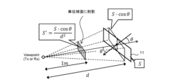
- FIG. 5 is a conceptual diagram for explaining the creation of a color image.
- the viewpoint is a transmission point Tx or a reception point Rx.
- the line of sight direction is the direction from the viewpoint to the structure surface 11.
- the line of sight direction is the direction from the viewpoint to the center point of the structure surface 11.
- the angle ⁇ is the angle between the line of sight direction and the normal direction of the structure surface 11. It can also be said that the angle ⁇ is the direction of the viewpoint (transmission point Tx or reception point Rx) seen from the structure surface 11.
- the distance d is the distance between the viewpoint along the line of sight direction and the structure surface 11.
- the color image creation unit 120 projects the structure surface 11 onto a unit sphere centered on the viewpoint. When the area of the original structure surface 11 is S, the area S' of the structure surface 11 projected onto the unit sphere is expressed as S ⁇ cos ⁇ /d 2 .
- the color image creation unit 120 projects all of the structure surfaces 11 seen from the viewpoint onto the same unit sphere. Although the line of sight direction and distance d may differ for each structure surface 11, all of the structure surfaces 11 are projected onto the same unit sphere. The color image creation unit 120 then expands the unit sphere onto a plane. This provides a color image of the structure surface 11 seen from the viewpoint.
- FIG. 6 shows an example of a color image seen from a transmitting point Tx and a color image seen from a receiving point Rx.
- each structure surface 11 is represented by a unique color assigned to each structure surface 11.
- the color image is generated taking occlusion into account.
- the environmental information 104 includes position information of the transmission point Tx, position information of the reception point Rx, and structure surface information (color, position, orientation, and size of each structure surface 11). Therefore, the color image creation unit 120 can create a color image seen from the transmission point Tx and a color image seen from the reception point Rx based on the environmental information 104. The created color images are stored in the storage device 102.
- step S130 Structural surface extraction process
- a propagation path that reaches a receiving point Rx from a transmitting point Tx with only one scattering and reflection is considered.
- a dominant one-scattering wave (reflected wave) is considered.
- a structure surface 11 that is visible from both the transmitting point Tx and the receiving point Rx is extracted.
- the structure surface extraction unit 130 extracts the structure surface 11 that is visible from both the transmission point Tx and the reception point Rx. Specifically, the structure surface extraction unit 130 compares the color image seen from the transmission point Tx with the color image seen from the reception point Rx, and extracts the structure surface 11 that has the same color in the two color images.
- the structure surface 11 that has the same color in the two color images is the structure surface 11 that is visible from both the transmission point Tx and the reception point Rx.
- the structure surface 11 that is visible from both the transmission point Tx and the reception point Rx is hereinafter referred to as the "target structure surface 11X.”
- step S140 the path gain calculation unit 140 calculates the path gain of the propagation path between the transmission point Tx and the reception point Rx passing through the target structure surface 11X. That is, the path gain calculation unit 140 calculates the path gain of the propagation path that is reflected and scattered at the target structure surface 11X.
- FIG. 7 shows a transmission point Tx, a reception point Rx, and a target structure surface 11X.
- the first angle ⁇ T is an angle ⁇ representing the direction of the transmission point Tx as seen from the target structure surface 11X.
- the first distance d1 is a distance d between the transmission point Tx and the target structure surface 11X.
- the second angle ⁇ R is an angle ⁇ representing the direction of the reception point Rx as seen from the target structure surface 11X.
- the second distance d2 is a distance d between the reception point Rx and the target structure surface 11X.
- the area of the target structure surface 11X is S.
- the first area S1 is the area of the target structure surface 11X seen from the transmission point Tx.
- the second area S2 is the area of the target structure surface 11X seen from the reception point Rx.
- the area S' of the structure surface 11 projected onto the unit sphere is expressed as S ⁇ cos ⁇ /d 2 . Therefore, a first area S1' and a second area S2' of the target structure surface 11X projected onto the unit sphere are respectively expressed by the following formulas (1) and (2).
- the path gain PG of the propagation path that is reflected and scattered on the target structure surface 11X depends on the first area S1' and the second area S2'. Specifically, the path gain PG of the propagation path that is reflected and scattered on the target structure surface 11X is expressed by the following equations (3) to (5). Note that "i" in the equations is an identifier of the target structure surface 11X and is different for each target structure surface 11X.
- C ⁇ expressed in formula (4) is a parameter corresponding to the reflection loss ⁇ of the target structure surface 11X.
- C b expressed in formula (5) is a reflection pattern indicating the level of the reflected wave (scattered wave) by the target structure surface 11X.
- Fig. 7 also shows the formula for the bistatic scattering cross section ⁇ of the flat plate.
- the reflection pattern C b is also included in the formula for the bistatic scattering cross section ⁇ , and is expressed by a sinc function with the first angle ⁇ T and the second angle ⁇ R as parameters.
- the path gain PG depends on the multiplication of the first area S1' and the second area S2'.
- the path gain PG also depends on the reflection pattern Cb of the target structure surface 11X.
- the first area S1' and the second area S2' can also be replaced with the number of pixels on the color image.
- the first number of pixels N P,T is the number of pixels on the color image of the target structure surface 11X seen from the transmitting point Tx.
- the second number of pixels N P,R is the number of pixels on the color image of the target structure surface 11X seen from the receiving point Rx.
- formula (3) is replaced with the following formulas (6) and (7).
- the 4 ⁇ /(H ⁇ W) in equation (7) is the area per pixel.
- the color image creation unit 120 described above expands the unit sphere onto a plane, and H ⁇ W represents the total number of pixels on the plane to which it is expanded.
- the environment information 104 includes the position information of the transmission point Tx, the position information of the reception point Rx, and the structure surface information (the color, position, orientation, and size of each structure surface 11). Therefore, the path gain calculation unit 140 can calculate the path gain PG based on the environment information 104 and the above formula.
- the path gain calculation unit 140 counts the number of first pixels N P,T and the number of second pixels N P,R in the color image. The path gain calculation unit 140 calculates the path gain PG for all target structure surfaces 11X (propagation paths).
- step S150 the reception power calculation unit 150 calculates the reception power (strength of the received radio wave) at the reception point Rx. Specifically, the reception power calculation unit 150 calculates the sum of the path gains for all the target structure surfaces 11X to calculate the reception power. In other words, the reception power calculation unit 150 calculates the reception power by combining the path gains for all the target structure surfaces 11X.
- Dynamic reflectors (RIS: Reconfigurable Intelligent Surface) are known for use in wireless communication.
- a dynamic reflector is composed of many reflecting elements and reflects incident radio waves.
- the reflection characteristics of the dynamic reflector such as the reflection direction, can be dynamically controlled.
- the dynamic reflector is a metasurface reflector.
- the reflection pattern Cb for calculating the path gain PG is corrected to correspond to the set value of the reflection angle of the dynamic reflector. Then, the radio wave propagation characteristics are estimated based on the reflection pattern Cb corresponding to the set value of the reflection angle of the dynamic reflector.
- the reflection pattern Cb represents the level of the reflected wave (scattered wave) by the reflecting surface of the dynamic reflector.
- the first angle ⁇ T is an angle representing the direction of the transmitting point Tx as seen from the reflecting surface of the dynamic reflector.
- the second angle ⁇ R is an angle representing the direction of the receiving point Rx as seen from the reflecting surface of the dynamic reflector.
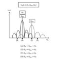
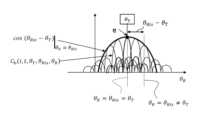
- the set reflection angle ⁇ Ris is the set value of the reflection angle of the dynamic reflector.
- the horizontal axis represents the second angle ⁇ R
- the vertical axis represents the level of the reflected wave (scattered wave) by the reflecting surface of the dynamic reflector.
- Fig. 8 shows a reflection pattern Cb when the first angle ⁇ T and the set reflection angle ⁇ Ris are the same, and a reflection pattern Cb when the first angle ⁇ T and the set reflection angle ⁇ Ris are different.
- Fig. 9 shows reflection patterns Cb for various set reflection angles ⁇ Ris .
- the reflection pattern Cb in the case of a dynamic reflector varies depending on the relationship between the first angle ⁇ T and the set reflection angle ⁇ Ris . Therefore, the reflection pattern Cb in the case of a dynamic reflector is expressed as a function of the first angle ⁇ T , the second angle ⁇ R, and the set reflection angle ⁇ Ris .
- the path gain PG in the case of a dynamic reflector is expressed by the following equation (8).
- an additional loss ⁇ may be added to the path gain PG in the case of a dynamic reflector.
- the additional loss ⁇ may be predetermined.
- the reflection pattern Cb in the case of a dynamic reflector is approximately represented by the following formula (9).
- the path gain calculation unit 140 calculates the path gain PG based on the above formula (8). More specifically, the environment information 104 also includes information about the dynamic reflector. The information about the dynamic reflector includes a flag indicating that it is a dynamic reflector, the set reflection angle ⁇ Ris of the dynamic reflector, the reflection pattern C b of the dynamic reflector (see FIGS. 8 and 9), the additional loss ⁇ , and the like. The path gain calculation unit 140 calculates the path gain PG when the target structure surface 11X is a reflecting surface of a dynamic reflector based on the environment information 104.
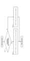
- FIG. 10 is a flowchart showing the path gain calculation process (step S140) according to this embodiment.
- the path gain calculation unit 140 determines whether the target structure surface 11X is a reflecting surface of a dynamic reflector based on the environmental information 104.
- step S141 If the target structure surface 11X is the reflecting surface of a dynamic reflector (step S141; Yes), the process proceeds to step S142.
- step S142 the path gain calculation unit 140 calculates the path gain PG based on the above formula (8).
- step S141 if the target structure surface 11X is not a reflecting surface of a dynamic reflector (step S141; No), the process proceeds to step S143.
- step S143 the path gain calculation unit 140 calculates the path gain PG based on the above formula (6).
- the path gain PG taking into account the characteristics of a dynamic reflector whose reflection direction is intentionally controlled.
- 1...wireless communication system 10...structure, 11...structure surface, 11X...target structure surface, 100...propagation characteristic estimation device, 101...processor, 102...storage device, 103...propagation characteristic estimation program, 104...environmental information, 105...communication interface, 106...user interface, 110...structure surface information creation unit, 120...color image creation unit, 130...structure surface extraction unit, 140...path gain calculation unit, 150...received power calculation unit
Landscapes
- Engineering & Computer Science (AREA)
- Computer Networks & Wireless Communication (AREA)
- Signal Processing (AREA)
- Monitoring And Testing Of Transmission In General (AREA)
Abstract
伝搬特性推定装置は、送信点と受信点の間の電波伝搬特性を推定する。環境情報は、送信点から受信点への電波を反射、散乱する構造物面の配置を示す。伝搬特性推定装置は、環境情報に基づいて、送信点と受信点の両方から見通しで見える構造物面を対象構造物面として抽出する。伝搬特性推定装置は、送信点から見える対象構造物面の面積である第1面積と、受信点から見える対象構造物面の面積である第2面積と、対象構造物面による反射波のレベルを表す反射パターンとに基づいて、対象構造物面を経由する送信点と受信点との間の伝搬パスの電波伝搬特性を推定する。対象構造物面が動的反射板の反射面である場合、伝搬特性推定装置は、動的反射板の反射角の設定値に応じた反射パターンに基づいて、電波伝搬特性を推定する。
Description
本発明は、送信点と受信点の間の電波伝搬特性を推定する技術に関する。
非特許文献1は、無線通信システムにおける電波伝搬特性を推定する一手法であるレイトレーシング法を開示している。
今井哲朗, "レイトレーシング法による移動伝搬シミュレーション," 電子情報通信学会論文誌(B), Vol.J92-B, No.9, pp.1333-1347, Sept. 2009.
無線通信システムにおける電波伝搬特性を推定する手法として、カラーイメージ法がある。カラーイメージ法によれば、送信点及び受信点から見た構造物面のカラーイメージが作成される。更に、カラーイメージに基づいて散乱波の伝搬パスが一括探索される。これにより、伝搬損失や受信電力といった電波伝搬特性が高速且つ高精度に推定される。
但し、既存のカラーイメージ法では、単なる構造物面の散乱特性しか考慮されていなかった。既存のカラーイメージ法では、反射方向を“意図的”に制御可能な動的反射板(RIS: Reconfigurable Intelligent Surface)の特性については考慮されていなかった。動的反射板の特性も考慮して電波伝搬特性を推定することができる技術が望まれる。
第1の観点は、送信点と受信点の間の電波伝搬特性を推定する伝搬特性推定装置に関する。
伝搬特性推定装置は、
1又は複数のプロセッサと、
送信点から受信点への電波を反射、散乱する構造物面の配置を示す環境情報を記憶する1又は複数の記憶装置と
を備える。
1又は複数のプロセッサは、環境情報に基づいて、送信点と受信点の両方から見通しで見える構造物面を対象構造物面として抽出する。
1又は複数のプロセッサは、送信点から見える対象構造物面の面積である第1面積と、受信点から見える対象構造物面の面積である第2面積と、対象構造物面による反射波のレベルを表す反射パターンとに基づいて、対象構造物面を経由する送信点と受信点との間の伝搬パスの電波伝搬特性を推定する。
対象構造物面が動的反射板の反射面である場合、1又は複数のプロセッサは、動的反射板の反射角の設定値に応じた反射パターンに基づいて、電波伝搬特性を推定する。
伝搬特性推定装置は、
1又は複数のプロセッサと、
送信点から受信点への電波を反射、散乱する構造物面の配置を示す環境情報を記憶する1又は複数の記憶装置と
を備える。
1又は複数のプロセッサは、環境情報に基づいて、送信点と受信点の両方から見通しで見える構造物面を対象構造物面として抽出する。
1又は複数のプロセッサは、送信点から見える対象構造物面の面積である第1面積と、受信点から見える対象構造物面の面積である第2面積と、対象構造物面による反射波のレベルを表す反射パターンとに基づいて、対象構造物面を経由する送信点と受信点との間の伝搬パスの電波伝搬特性を推定する。
対象構造物面が動的反射板の反射面である場合、1又は複数のプロセッサは、動的反射板の反射角の設定値に応じた反射パターンに基づいて、電波伝搬特性を推定する。
第2の観点は、送信点と受信点の間の電波伝搬特性を推定する伝搬特性推定方法に関する。
伝搬特性推定方法は、
送信点から受信点への電波を反射、散乱する構造物面の配置を示す環境情報を取得することと、
環境情報に基づいて、送信点と受信点の両方から見通しで見える構造物面を対象構造物面として抽出することと、
送信点から見える対象構造物面の面積である第1面積と、受信点から見える対象構造物面の面積である第2面積と、対象構造物面による反射波のレベルを表す反射パターンとに基づいて、対象構造物面を経由する送信点と受信点との間の伝搬パスの電波伝搬特性を推定することと
を含む。
電波伝搬特性を推定することは、対象構造物面が動的反射板の反射面である場合、動的反射板の反射角の設定値に応じた反射パターンに基づいて電波伝搬特性を推定することを含む。
伝搬特性推定方法は、
送信点から受信点への電波を反射、散乱する構造物面の配置を示す環境情報を取得することと、
環境情報に基づいて、送信点と受信点の両方から見通しで見える構造物面を対象構造物面として抽出することと、
送信点から見える対象構造物面の面積である第1面積と、受信点から見える対象構造物面の面積である第2面積と、対象構造物面による反射波のレベルを表す反射パターンとに基づいて、対象構造物面を経由する送信点と受信点との間の伝搬パスの電波伝搬特性を推定することと
を含む。
電波伝搬特性を推定することは、対象構造物面が動的反射板の反射面である場合、動的反射板の反射角の設定値に応じた反射パターンに基づいて電波伝搬特性を推定することを含む。
第3の観点は、送信点と受信点の間の電波伝搬特性を推定する伝搬特性推定プログラムに関する。伝搬特性推定プログラムは、コンピュータによって実行される。
伝搬特性推定プログラムは、
送信点から受信点への電波を反射、散乱する構造物面の配置を示す環境情報を取得することと、
環境情報に基づいて、送信点と受信点の両方から見通しで見える構造物面を対象構造物面として抽出することと、
送信点から見える対象構造物面の面積である第1面積と、受信点から見える対象構造物面の面積である第2面積と、対象構造物面による反射波のレベルを表す反射パターンとに基づいて、対象構造物面を経由する送信点と受信点との間の伝搬パスの電波伝搬特性を推定することと
をコンピュータに実行させる。
電波伝搬特性を推定することは、対象構造物面が動的反射板の反射面である場合、動的反射板の反射角の設定値に応じた反射パターンに基づいて電波伝搬特性を推定することを含む。
伝搬特性推定プログラムは、
送信点から受信点への電波を反射、散乱する構造物面の配置を示す環境情報を取得することと、
環境情報に基づいて、送信点と受信点の両方から見通しで見える構造物面を対象構造物面として抽出することと、
送信点から見える対象構造物面の面積である第1面積と、受信点から見える対象構造物面の面積である第2面積と、対象構造物面による反射波のレベルを表す反射パターンとに基づいて、対象構造物面を経由する送信点と受信点との間の伝搬パスの電波伝搬特性を推定することと
をコンピュータに実行させる。
電波伝搬特性を推定することは、対象構造物面が動的反射板の反射面である場合、動的反射板の反射角の設定値に応じた反射パターンに基づいて電波伝搬特性を推定することを含む。
本発明によれば、反射方向が意図的に制御される動的反射板の特性も考慮して電波伝搬特性を推定することが可能となる。
添付図面を参照して、本発明の実施の形態を説明する。
1.伝搬特性推定装置の概要
図1は、無線通信システム1を示す概略図である。無線通信システム1は、電波を送信する送信点Txと、電波を受信する受信点Rxを含んでいる。電波は建物等によって反射、散乱されるため、送信点Txと受信点Rxとの間には複数の伝搬パスが存在する。
図1は、無線通信システム1を示す概略図である。無線通信システム1は、電波を送信する送信点Txと、電波を受信する受信点Rxを含んでいる。電波は建物等によって反射、散乱されるため、送信点Txと受信点Rxとの間には複数の伝搬パスが存在する。
送信点Txから受信点Rxへの電波伝搬に影響を与える物体を、以下、「構造物10」と呼ぶ。構造物10としては、ビル、壁、等が例示される。典型的には、送信点Tx及び受信点Rxを含む電波伝送エリアには、多数の構造物10が存在する。電波は、構造物10の面で反射、散乱する。電波が反射、散乱する構造物10の面を、以下、「構造物面11」と呼ぶ。例えば、構造物面11は、ビルの壁面である。1つの構造物10が複数の構造物面11(例:11a~11d)を有する場合、それら複数の構造物面11は互いに区別される。
本実施の形態によれば、無線通信システム1における電波伝搬特性、すなわち、送信点Txと受信点Rxとの間の電波伝搬特性が推定される。特に、構造物面11での電波の反射、散乱を考慮して、送信点Txと受信点Rxとの間の電波伝搬特性が推定される。電波伝搬特性としては、伝搬損失、受信波の電波強度、受信電力、遅延時間、等が挙げられる。
図2は、送信点Txと受信点Rxとの間の電波伝搬特性を推定する伝搬特性推定装置100の構成例を示すブロック図である。伝搬特性推定装置100は、1又は複数のプロセッサ101(以下、単に「プロセッサ101」と呼ぶ)と1又は複数の記憶装置102(以下、単に「記憶装置102」と呼ぶ)を含むコンピュータである。プロセッサ101は、各種処理を実行する。プロセッサ101としては、CPU(Central Processing Unit)、ASIC(Application Specific Integrated Circuit)、FPGA(Field-Programmable Gate Array)、等が例示される。記憶装置102は、各種情報を格納する。記憶装置102としては、HDD(Hard Disk Drive)、SSD(Solid State Drive)、揮発性メモリ、不揮発性メモリ、等が例示される。
伝搬特性推定プログラム103は、プロセッサ101によって実行されるコンピュータプログラム(ソフトウェア)である。伝搬特性推定プログラム103を実行するプロセッサ101と記憶装置102との協働により、伝搬特性推定装置100の機能が実現されてもよい。伝搬特性推定プログラム103は、記憶装置102に格納される。伝搬特性推定プログラム103は、コンピュータ読み取り可能な記録媒体に記録されてもよい。伝搬特性推定プログラム103は、ネットワーク経由で提供されてもよい。
環境情報104は、無線通信システム1における電波伝搬特性の推定に必要な情報である。例えば、環境情報104は、送信点Txの位置情報及び受信点Rxの位置情報を含んでいる。また、環境情報104は、送信点Txから受信点Rxへの電波伝搬に影響を与える構造物10の配置を示す構造物情報を含んでいる。構造物情報は、各構造物10の各構造物面11の配置(位置、向き、サイズ)、反射係数、等を含んでいる。構造物情報は、3次元CAD(Computer-Aided Design)データ、BIM(Building Information Modeling)データ、等で与えられてもよい。環境情報104は、無線通信システム1において使用される電波の波長の情報を含んでいてもよい。環境情報104は、記憶装置102に格納される。
伝搬特性推定装置100は、更に、外部と通信を行う通信インタフェース105を備えていてもよい。環境情報104は、通信インタフェース105を介して伝搬特性推定装置100に提供されてもよい。
伝搬特性推定装置100は、更に、ユーザからの入力を受け付け、また、ユーザに各種情報を提示するユーザインタフェース106を備えていてもよい。ユーザインタフェース106は入力装置と表示装置を含んでいる。入力装置としては、キーボード、マウス、タッチパネル、等が例示される。ユーザは、入力装置を用いることによって、伝搬特性推定装置100を操作することができる。電波伝搬特性の推定結果は、表示装置に表示される。
無線通信システム1における電波伝搬特性を推定する一つの手法として「カラーイメージ法」がある。カラーイメージ法は、電波伝搬特性を高速且つ高精度に推定することができる。以下、カラーイメージ法について詳しく説明する。
図3は、カラーイメージ法に関連する機能構成例を示すブロック図である。伝搬特性推定装置100は、機能ブロックとして、構造物面情報作成部110、カラーイメージ作成部120、構造物面抽出部130、パスゲイン算出部140、及び受信電力算出部150を含んでいる。これら機能ブロックは、伝搬特性推定プログラム103を実行するプロセッサ101と記憶装置102との協働により実現されてもよい。図4は、カラーイメージ法による伝搬特性推定処理を示すフローチャートである。
1-1.構造物面情報作成処理(ステップS110)
ステップS110において、構造物面情報作成部110は、環境情報104に基づいて、各構造物10の各構造物面11を認識する。1つの構造物10が複数の構造物面11(例:11a~11d)を有する場合、それら複数の構造物面11は互いに区別される(図1参照)。そして、構造物面情報作成部110は、各構造物面11に識別情報を割り当てる。識別情報は、構造物面11毎に異なる。
ステップS110において、構造物面情報作成部110は、環境情報104に基づいて、各構造物10の各構造物面11を認識する。1つの構造物10が複数の構造物面11(例:11a~11d)を有する場合、それら複数の構造物面11は互いに区別される(図1参照)。そして、構造物面情報作成部110は、各構造物面11に識別情報を割り当てる。識別情報は、構造物面11毎に異なる。
例えば、構造物面11の識別情報は“色”である。この場合、構造物面情報作成部110は、構造物面11毎に異なる色を割り当てる。色は、例えばRGB値で表される。例えば、構造物面11に割り当てられるRGB値は(R,G,B)=(10~249,10~249,10~249)である。特別な色である(0,0,0)及び(255,255,255)は背景と地面に割り当てられる。
構造物面情報は、各構造物面11に関する情報である。具体的には、構造物面情報は、各構造物面11の識別情報(色)、配置(位置、向き、サイズ)、反射係数、等を含んでいる。各構造物面11の位置、向き、サイズ、反射係数、等は環境情報104に予め登録されている。構造物面情報作成部110は、構造面情報を作成し、構造物面情報を環境情報104に追加する。
尚、構造物面11の識別情報は識別番号であってもよい。以下の説明では、構造物面11の識別情報が色である場合について説明する。色の表現形式は、RGBに限定されない。
1-2.カラーイメージ作成処理(ステップS120)
ステップS120において、カラーイメージ作成部120は、送信点Txと受信点Rxのそれぞれから見た構造物面11の2次元イメージを作成する。各構造物面11に固有の色が割り当てられる場合、2次元イメージは2次元カラーイメージとなる。その2次元カラーイメージを、以下、単に「カラーイメージ」と呼ぶ。
ステップS120において、カラーイメージ作成部120は、送信点Txと受信点Rxのそれぞれから見た構造物面11の2次元イメージを作成する。各構造物面11に固有の色が割り当てられる場合、2次元イメージは2次元カラーイメージとなる。その2次元カラーイメージを、以下、単に「カラーイメージ」と呼ぶ。
図5は、カラーイメージの作成を説明するための概念図である。図5において、視点(viewpoint)は、送信点Txあるいは受信点Rxである。視線方向は、視点から構造物面11への方向である。例えば、視線方向は、視点から構造物面11の中心点への方向である。角度θは、視線方向と構造物面11の法線方向のなす角である。角度θは、構造物面11から見た視点(送信点Txあるいは受信点Rx)の方向であると言うこともできる。距離dは、視線方向に沿った視点と構造物面11との間の距離である。カラーイメージ作成部120は、構造物面11を、視点を中心とする単位球面に射影する。元の構造物面11の面積がSである場合、単位球面に射影された構造物面11の面積S’はS・cosθ/d2で表される。
カラーイメージ作成部120は、視点から見た全ての構造物面11を同じ単位球面に射影する。視線方向及び距離dは構造物面11毎に異なり得るが、全ての構造物面11が同じ単位球面に射影される。そして、カラーイメージ作成部120は、単位球面を平面に展開する。これにより、視点から見た構造物面11のカラーイメージが得られる。
図6は、送信点Txから見たカラーイメージと受信点Rxから見たカラーイメージの例を示している。カラーイメージにおいて、各構造物面11は、各構造物面11に割り当てられた固有の色で表されている。カラーイメージは、オクルージョンを考慮して生成される。
上述の通り、環境情報104は、送信点Txの位置情報、受信点Rxの位置情報、及び構造物面情報(各構造物面11の色、位置、向き、サイズ)を含んでいる。従って、カラーイメージ作成部120は、環境情報104に基づいて、送信点Txから見たカラーイメージと受信点Rxから見たカラーイメージを作成することができる。作成されたカラーイメージは、記憶装置102に格納される。
1-3.構造物面抽出処理(ステップS130)
カラーイメージ法では、1回の散乱、反射だけで送信点Txから受信点Rxへ到達する伝搬パスが考慮される。つまり、支配的な一回散乱波(反射波)が考慮される。そのために、送信点Txと受信点Rxの両方から見通しで見える構造物面11が抽出される。
カラーイメージ法では、1回の散乱、反射だけで送信点Txから受信点Rxへ到達する伝搬パスが考慮される。つまり、支配的な一回散乱波(反射波)が考慮される。そのために、送信点Txと受信点Rxの両方から見通しで見える構造物面11が抽出される。
ステップS130において、構造物面抽出部130は、送信点Txと受信点Rxの両方から見通しで見える構造物面11を抽出する。具体的には、構造物面抽出部130は、送信点Txから見たカラーイメージと受信点Rxから見たカラーイメージを比較し、2つのカラーイメージの中で同じ色を有する構造物面11を抽出する。2つのカラーイメージの中で同じ色を有する構造物面11が、送信点Txと受信点Rxの両方から見通しで見える構造物面11である。送信点Txと受信点Rxの両方から見通しで見える構造物面11を、以下、「対象構造物面11X」と呼ぶ。
送信点Txから見たカラーイメージと受信点Rxから見たカラーイメージを比較することによって、1以上の対象構造物面11Xを一括探索することが可能となる。言い換えれば、送信点Txから受信点Rxへの1以上の伝搬パスを一括探索することが可能となる。このように伝搬パスを一括探索可能であることは、電波伝搬特性の高速化に寄与する。
1-4.パスゲイン算出処理(ステップS140)
ステップS140において、パスゲイン算出部140は、対象構造物面11Xを経由する送信点Txと受信点Rxとの間の伝搬パスのパスゲインを算出する。つまり、パスゲイン算出部140は、対象構造物面11Xで反射、散乱する伝搬パスのパスゲインを算出する。
ステップS140において、パスゲイン算出部140は、対象構造物面11Xを経由する送信点Txと受信点Rxとの間の伝搬パスのパスゲインを算出する。つまり、パスゲイン算出部140は、対象構造物面11Xで反射、散乱する伝搬パスのパスゲインを算出する。
図7は、送信点Tx、受信点Rx、及び対象構造物面11Xを示している。第1角度θTは、対象構造物面11Xから見た送信点Txの方向を表す角度θである。第1距離d1は、送信点Txと対象構造物面11Xとの間の距離dである。第2角度θRは、対象構造物面11Xから見た受信点Rxの方向を表す角度θである。第2距離d2は、受信点Rxと対象構造物面11Xとの間の距離dである。対象構造物面11Xの面積はSである。第1面積S1は、送信点Txから見える対象構造物面11Xの面積である。第2面積S2は、受信点Rxから見える対象構造物面11Xの面積である。図5で示された通り、単位球面に射影された構造物面11の面積S’はS・cosθ/d2で表される。よって、単位球面に射影された対象構造物面11Xの第1面積S1’及び第2面積S2’は、それぞれ、次の式(1)及び式(2)で表される。


対象構造物面11Xで反射、散乱する伝搬パスのパスゲインPGは、第1面積S1’と第2面積S2’に依存する。具体的には、対象構造物面11Xで反射、散乱する伝搬パスのパスゲインPGは、次の式(3)~(5)で表される。尚、式中の“i”は、対象構造物面11Xの識別子であり、対象構造物面11X毎に異なる。



式(4)で表されるCΓは、対象構造物面11Xの反射損失Γに相当するパラメータである。式(5)で表されるCbは、対象構造物面11Xによる反射波(散乱波)のレベルを表す反射パターンである。図7には、平板のバイスタティック散乱断面積σの式も示されている。反射パターンCbは、バイスタティック散乱断面積σの式にも含まれており、第1角度θTと第2角度θRをパラメータとするsinc関数で表される。
このように、パスゲインPGは、第1面積S1’と第2面積S2’の乗算に依存する。また、パスゲインPGは、対象構造物面11Xの反射パターンCbに依存する。
第1面積S1’と第2面積S2’は、カラーイメージ上のピクセル数で置き換えることもできる。第1ピクセル数NP,Tは、送信点Txから見た対象構造物面11Xのカラーイメージ上のピクセル数である。第2ピクセル数NP,Rは、受信点Rxから見た対象構造物面11Xのカラーイメージ上のピクセル数である。この場合、式(3)は、下記式(6)、式(7)で置き換えられる。


式(7)で表される4π/(H・W)は、1ピクセル当たりの面積である。上述のカラーイメージ作成部120は単位球面を平面に展開するが、H・Wは展開先の平面の総ピクセル数を表している。
上述の通り、環境情報104は、送信点Txの位置情報、受信点Rxの位置情報、及び構造物面情報(各構造物面11の色、位置、向き、サイズ)を含んでいる。従って、パスゲイン算出部140は、環境情報104と上記式に基づいてパスゲインPGを算出することができる。式(6)を用いる場合、パスゲイン算出部140は、カラーイメージ内の第1ピクセル数NP,T及び第2ピクセル数NP,Rをカウントする。パスゲイン算出部140は、全ての対象構造物面11X(伝搬パス)に対するパスゲインPGを算出する。
1-5.受信電力算出処理(ステップS150)
ステップS150において、受信電力算出部150は、受信点Rxにおける受信電力(受信電波の強度)を算出する。具体的には、受信電力算出部150は、全ての対象構造物面11Xに対するパスゲインの総和を計算して、受信電力を算出する。言い換えれば、受信電力算出部150は、全ての対象構造物面11Xに対するパスゲインを合成して、受信電力を算出する。
ステップS150において、受信電力算出部150は、受信点Rxにおける受信電力(受信電波の強度)を算出する。具体的には、受信電力算出部150は、全ての対象構造物面11Xに対するパスゲインの総和を計算して、受信電力を算出する。言い換えれば、受信電力算出部150は、全ての対象構造物面11Xに対するパスゲインを合成して、受信電力を算出する。
2.動的反射板も考慮したカラーイメージ法
無線通信に利用される動的反射板(RIS: Reconfigurable Intelligent Surface)が知られている。動的反射板は、多数の反射素子から構成され、入射される電波を反射する。動的反射板の反射方向等の反射特性は、動的に制御可能である。例えば、動的反射板は、メタサーフェス反射板である。動的反射板を利用することによって、障害物を迂回する伝搬パスを形成したり、単一の端末装置に対して複数の伝搬パスを形成したりすることが可能となる。これにより、通信品質や空間多重数といった通信性能を向上させることが可能となる。
無線通信に利用される動的反射板(RIS: Reconfigurable Intelligent Surface)が知られている。動的反射板は、多数の反射素子から構成され、入射される電波を反射する。動的反射板の反射方向等の反射特性は、動的に制御可能である。例えば、動的反射板は、メタサーフェス反射板である。動的反射板を利用することによって、障害物を迂回する伝搬パスを形成したり、単一の端末装置に対して複数の伝搬パスを形成したりすることが可能となる。これにより、通信品質や空間多重数といった通信性能を向上させることが可能となる。
既存のカラーイメージ法では、単なる構造物面11の散乱特性しか考慮されていなかった。既存のカラーイメージ法では、反射方向を“意図的”に制御可能な動的反射板の特性については考慮されていなかった。そこで、本実施の形態は、動的反射板の特性も考慮してカラーイメージ法により電波伝搬特性を推定する技術を提案する。
本実施の形態によれば、対象構造物面11Xが動的反射板の反射面である場合、パスゲインPGを算出するための反射パターンCbが、動的反射板の反射角の設定値に応じたものに補正される。そして、動的反射板の反射角の設定値に応じた反射パターンCbに基づいて、電波伝搬特性が推定される。
図8及び図9は、動的反射板の場合の反射パターンCbを説明するための概念図である。反射パターンCbは、動的反射板の反射面による反射波(散乱波)のレベルを表す。第1角度θTは、動的反射板の反射面から見た送信点Txの方向を表す角度である。第2角度θRは、動的反射板の反射面から見た受信点Rxの方向を表す角度である。設定反射角度θRisは、動的反射板の反射角の設定値である。図8及び図9において、横軸は第2角度θRを表し、縦軸は動的反射板の反射面による反射波(散乱波)のレベルを表す。
図8には、第1角度θTと設定反射角度θRisが同じである場合の反射パターンCbと、第1角度θTと設定反射角度θRisが異なる場合の反射パターンCbが示されている。図9には、様々な設定反射角度θRisに対する反射パターンCbが示されている。図8及び図9に示されるように、動的反射板の場合の反射パターンCbは、第1角度θTと設定反射角度θRisの関係によって変動する。よって、動的反射板の場合の反射パターンCbは、第1角度θTと第2角度θRと設定反射角度θRisの関数で表されることになる。
図8及び図9に示される反射パターンCbを用いることによって、動的反射板の場合のパスゲインPGは、次の式(8)で表される。

式(8)に示されるように、動的反射板の場合のパスゲインPGに追加損失ηが追加されてもよい。追加損失ηは、予め定められていてもよい。
図9には、θR=θRisの場合の様々な設定反射角度θRisに対する反射パターンCbの値を近似的に表す関数も示されている。動的反射板の場合の反射パターンCbは、近似的に次の式(9)で表される。

対象構造物面11Xが動的反射板の反射面である場合、パスゲイン算出部140は、上記式(8)に基づいてパスゲインPGを算出する。より詳細には、環境情報104は、動的反射板に関する情報も含んでいる。動的反射板に関する情報は、動的反射板であることを示すフラグ、動的反射板の設定反射角度θRis、動的反射板の反射パターンCb(図8、図9参照)、追加損失η、等を含んでいる。パスゲイン算出部140は、環境情報104に基づいて、対象構造物面11Xが動的反射板の反射面である場合のパスゲインPGを算出する。
図10は、本実施の形態に係るパスゲイン算出処理(ステップS140)を示すフローチャートである。ステップS141において、パスゲイン算出部140は、環境情報104に基づいて、対象構造物面11Xが動的反射板の反射面であるか否かを判定する。
対象構造物面11Xが動的反射板の反射面である場合(ステップS141;Yes)、処理はステップS142に進む。ステップS142において、パスゲイン算出部140は、上記式(8)に基づいてパスゲインPGを算出する。
一方、対象構造物面11Xが動的反射板の反射面ではない場合(ステップS141;No)、処理はステップS143に進む。ステップS143において、パスゲイン算出部140は、上記式(6)に基づいてパスゲインPGを算出する。
以上に説明されたように、本実施の形態によれば、反射方向が意図的に制御される動的反射板の特性も考慮してパスゲインPGを算出することが可能となる。つまり、動的反射板の特性をカラーイメージ法において考慮することが可能となる。すなわち、動的反射板の特性も考慮して電波伝搬特性を高速に推定することが可能となる。
1…無線通信システム, 10…構造物, 11…構造物面, 11X…対象構造物面, 100…伝搬特性推定装置, 101…プロセッサ, 102…記憶装置, 103…伝搬特性推定プログラム, 104…環境情報, 105…通信インタフェース, 106…ユーザインタフェース, 110…構造物面情報作成部, 120…カラーイメージ作成部, 130…構造物面抽出部, 140…パスゲイン算出部, 150…受信電力算出部
Claims (7)
- 送信点と受信点の間の電波伝搬特性を推定する伝搬特性推定装置であって、
1又は複数のプロセッサと、
前記送信点から前記受信点への電波を反射、散乱する構造物面の配置を示す環境情報を記憶する1又は複数の記憶装置と
を備え、
前記1又は複数のプロセッサは、
前記環境情報に基づいて、前記送信点と前記受信点の両方から見通しで見える前記構造物面を対象構造物面として抽出し、
前記送信点から見える前記対象構造物面の面積である第1面積と、前記受信点から見える前記対象構造物面の面積である第2面積と、前記対象構造物面による反射波のレベルを表す反射パターンとに基づいて、前記対象構造物面を経由する前記送信点と前記受信点との間の伝搬パスの前記電波伝搬特性を推定する
ように構成され、
前記対象構造物面が動的反射板の反射面である場合、前記1又は複数のプロセッサは、前記動的反射板の反射角の設定値に応じた前記反射パターンに基づいて、前記電波伝搬特性を推定する
伝搬特性推定装置。 - 請求項1に記載の伝搬特性推定装置であって、
θTは、前記動的反射板の前記反射面から見た前記送信点の方向を表す角度であり、
θRは、前記動的反射板の前記反射面から見た前記受信点の方向を表す角度であり、
θRisは、前記動的反射板の前記反射角の前記設定値であり、
前記動的反射板の前記反射角の前記設定値に応じた前記反射パターンは、θT、θR、及びθRisの関数で表される
伝搬特性推定装置。 - 請求項2に記載の伝搬特性推定装置であって、
前記動的反射板の前記反射角の前記設定値に応じた前記反射パターンは、近似的にcos(θRis-θT)で表される
伝搬特性推定装置。 - 請求項1乃至3のいずれか一項に記載の伝搬特性推定装置であって、
前記1又は複数のプロセッサは、前記1面積と前記第2面積と前記反射パターンに基づいて、前記対象構造物面を経由した前記送信点と前記受信点との間の前記伝搬パスのパスゲインを算出し、前記パスゲインに基づいて前記電波伝搬特性を推定する
伝搬特性推定装置。 - 請求項4に記載の伝搬特性推定装置であって、
前記対象構造物面が前記動的反射板の前記反射面である場合、前記1又は複数のプロセッサは、前記パスゲインに追加損失を追加する
伝搬特性推定装置。 - 送信点と受信点の間の電波伝搬特性を推定する伝搬特性推定方法であって、
前記送信点から前記受信点への電波を反射、散乱する構造物面の配置を示す環境情報を取得することと、
前記環境情報に基づいて、前記送信点と前記受信点の両方から見通しで見える前記構造物面を対象構造物面として抽出することと、
前記送信点から見える前記対象構造物面の面積である第1面積と、前記受信点から見える前記対象構造物面の面積である第2面積と、前記対象構造物面による反射波のレベルを表す反射パターンとに基づいて、前記対象構造物面を経由する前記送信点と前記受信点との間の伝搬パスの前記電波伝搬特性を推定することと
を含み、
前記電波伝搬特性を推定することは、前記対象構造物面が動的反射板の反射面である場合、前記動的反射板の反射角の設定値に応じた前記反射パターンに基づいて前記電波伝搬特性を推定することを含む
伝搬特性推定方法。 - 送信点と受信点の間の電波伝搬特性を推定する伝搬特性推定プログラムであって、
前記伝搬特性推定プログラムは、コンピュータによって実行され、
前記送信点から前記受信点への電波を反射、散乱する構造物面の配置を示す環境情報を取得することと、
前記環境情報に基づいて、前記送信点と前記受信点の両方から見通しで見える前記構造物面を対象構造物面として抽出することと、
前記送信点から見える前記対象構造物面の面積である第1面積と、前記受信点から見える前記対象構造物面の面積である第2面積と、前記対象構造物面による反射波のレベルを表す反射パターンとに基づいて、前記対象構造物面を経由する前記送信点と前記受信点との間の伝搬パスの前記電波伝搬特性を推定することと
を前記コンピュータに実行させ、
前記電波伝搬特性を推定することは、前記対象構造物面が動的反射板の反射面である場合、前記動的反射板の反射角の設定値に応じた前記反射パターンに基づいて前記電波伝搬特性を推定することを含む
伝搬特性推定プログラム。
Priority Applications (2)
| Application Number | Priority Date | Filing Date | Title |
|---|---|---|---|
| JP2025529009A JPWO2025004136A1 (ja) | 2023-06-26 | 2023-06-26 | |
| PCT/JP2023/023553 WO2025004136A1 (ja) | 2023-06-26 | 2023-06-26 | 伝搬特性推定装置、伝搬特性推定方法、及び伝搬特性推定プログラム |
Applications Claiming Priority (1)
| Application Number | Priority Date | Filing Date | Title |
|---|---|---|---|
| PCT/JP2023/023553 WO2025004136A1 (ja) | 2023-06-26 | 2023-06-26 | 伝搬特性推定装置、伝搬特性推定方法、及び伝搬特性推定プログラム |
Publications (1)
| Publication Number | Publication Date |
|---|---|
| WO2025004136A1 true WO2025004136A1 (ja) | 2025-01-02 |
Family
ID=93938014
Family Applications (1)
| Application Number | Title | Priority Date | Filing Date |
|---|---|---|---|
| PCT/JP2023/023553 Ceased WO2025004136A1 (ja) | 2023-06-26 | 2023-06-26 | 伝搬特性推定装置、伝搬特性推定方法、及び伝搬特性推定プログラム |
Country Status (2)
| Country | Link |
|---|---|
| JP (1) | JPWO2025004136A1 (ja) |
| WO (1) | WO2025004136A1 (ja) |
Citations (1)
| Publication number | Priority date | Publication date | Assignee | Title |
|---|---|---|---|---|
| JP2023004867A (ja) * | 2021-06-25 | 2023-01-17 | 株式会社Nttドコモ | 電波伝搬推定装置及び電波伝搬推定方法 |
-
2023
- 2023-06-26 WO PCT/JP2023/023553 patent/WO2025004136A1/ja not_active Ceased
- 2023-06-26 JP JP2025529009A patent/JPWO2025004136A1/ja active Pending
Patent Citations (1)
| Publication number | Priority date | Publication date | Assignee | Title |
|---|---|---|---|---|
| JP2023004867A (ja) * | 2021-06-25 | 2023-01-17 | 株式会社Nttドコモ | 電波伝搬推定装置及び電波伝搬推定方法 |
Non-Patent Citations (1)
| Title |
|---|
| TAKAHIRO TOMIE, SATOSHI SUYAMA, KOSHIRO KITAO, MITSUKI NAKAMURA: "New estimation method for radio wave propagation characteristics using color image", IEICE TECHNICAL REPORT, AP, IEICE, JP, vol. 122, no. 153 (AP2022-67), 23 August 2022 (2022-08-23), JP, pages 17 - 22, XP009559637 * |
Also Published As
| Publication number | Publication date |
|---|---|
| JPWO2025004136A1 (ja) | 2025-01-02 |
Similar Documents
| Publication | Publication Date | Title |
|---|---|---|
| JP2021530821A (ja) | 三次元無線モデル構築を実行するための方法、装置およびコンピュータプログラム | |
| CN111355544B (zh) | 一种城市环境电波路径预测方法和装置 | |
| TWI608744B (zh) | 估算裝置及其無線網路之通訊品質估算方法及電表安裝方法 | |
| WO2017162181A1 (zh) | 业务指标显示的方法和设备 | |
| JP2023012275A (ja) | 鉄筋コンクリート構造体の構造推定装置並びに方法 | |
| KR20190018233A (ko) | 다중 센서 시뮬레이션 장치 및 다중 센서 시뮬레이션 방법 | |
| JP7601211B2 (ja) | 情報処理システム、電波伝搬シミュレーション方法、及びプログラム | |
| Lin et al. | Non-line-of-sight target imaging in tomographic SAR by multipath signal analysis | |
| WO2025004136A1 (ja) | 伝搬特性推定装置、伝搬特性推定方法、及び伝搬特性推定プログラム | |
| CN113111524B (zh) | 基于远场测试的天线隔离度预测方法、存储介质和装置 | |
| CN114943809A (zh) | 一种地图模型的生成方法、装置及存储介质 | |
| WO2025004135A1 (ja) | 伝搬特性推定装置、伝搬特性推定方法、及び伝搬特性推定プログラム | |
| WO2019105194A1 (zh) | 一种传播路径搜索方法以及装置 | |
| US20250190642A1 (en) | Distance-based estimation of energy propagation variation in synthetic three-dimensional scenes | |
| CN120034277A (zh) | 信号传播损耗获取方法、装置、电子设备及存储介质 | |
| JP6879386B2 (ja) | 合成開口レーダの信号処理装置及び信号処理方法 | |
| US12085641B2 (en) | Image processing device, image processing method, and image processing computer program | |
| JP7593480B2 (ja) | 情報処理システム、レイトレース方法、及びプログラム | |
| JP7598307B2 (ja) | モデル作成装置、伝搬特性特定装置、モデル作成方法及びプログラム | |
| CN114863031B (zh) | 一种三维模型的重叠度计算方法、装置、设备及存储介质 | |
| JP6741154B2 (ja) | 情報処理装置、情報処理方法、及びプログラム | |
| JP2019124489A (ja) | レーダ反射断面積計算装置、レーダ反射断面積計算方法、およびレーダ反射断面積計算プログラム | |
| CN115236687A (zh) | 物体跟踪方法、装置、设备及存储介质 | |
| CN119310528B (zh) | 角反射器部署方案的确定方法、设备和可读存储介质 | |
| JP2022106445A (ja) | モデル作成装置、モデル作成方法及びプログラム |
Legal Events
| Date | Code | Title | Description |
|---|---|---|---|
| 121 | Ep: the epo has been informed by wipo that ep was designated in this application |
Ref document number: 23943541 Country of ref document: EP Kind code of ref document: A1 |
|
| ENP | Entry into the national phase |
Ref document number: 2025529009 Country of ref document: JP Kind code of ref document: A |
|
| NENP | Non-entry into the national phase |
Ref country code: DE |