WO2024262099A1 - 回転装置 - Google Patents
回転装置 Download PDFInfo
- Publication number
- WO2024262099A1 WO2024262099A1 PCT/JP2024/008777 JP2024008777W WO2024262099A1 WO 2024262099 A1 WO2024262099 A1 WO 2024262099A1 JP 2024008777 W JP2024008777 W JP 2024008777W WO 2024262099 A1 WO2024262099 A1 WO 2024262099A1
- Authority
- WO
- WIPO (PCT)
- Prior art keywords
- wall surface
- turbine
- vane
- vane plate
- vanes
- Prior art date
- Legal status (The legal status is an assumption and is not a legal conclusion. Google has not performed a legal analysis and makes no representation as to the accuracy of the status listed.)
- Ceased
Links
Images


Classifications
-
- F—MECHANICAL ENGINEERING; LIGHTING; HEATING; WEAPONS; BLASTING
- F04—POSITIVE - DISPLACEMENT MACHINES FOR LIQUIDS; PUMPS FOR LIQUIDS OR ELASTIC FLUIDS
- F04D—NON-POSITIVE-DISPLACEMENT PUMPS
- F04D29/00—Details, component parts, or accessories
- F04D29/40—Casings; Connections of working fluid
- F04D29/42—Casings; Connections of working fluid for radial or helico-centrifugal pumps
- F04D29/44—Fluid-guiding means, e.g. diffusers
- F04D29/46—Fluid-guiding means, e.g. diffusers adjustable
- F04D29/462—Fluid-guiding means, e.g. diffusers adjustable especially adapted for elastic fluid pumps
-
- F—MECHANICAL ENGINEERING; LIGHTING; HEATING; WEAPONS; BLASTING
- F02—COMBUSTION ENGINES; HOT-GAS OR COMBUSTION-PRODUCT ENGINE PLANTS
- F02B—INTERNAL-COMBUSTION PISTON ENGINES; COMBUSTION ENGINES IN GENERAL
- F02B37/00—Engines characterised by provision of pumps driven at least for part of the time by exhaust
- F02B37/12—Control of the pumps
- F02B37/24—Control of the pumps by using pumps or turbines with adjustable guide vanes
-
- F—MECHANICAL ENGINEERING; LIGHTING; HEATING; WEAPONS; BLASTING
- F04—POSITIVE - DISPLACEMENT MACHINES FOR LIQUIDS; PUMPS FOR LIQUIDS OR ELASTIC FLUIDS
- F04D—NON-POSITIVE-DISPLACEMENT PUMPS
- F04D29/00—Details, component parts, or accessories
- F04D29/26—Rotors specially for elastic fluids
- F04D29/28—Rotors specially for elastic fluids for centrifugal or helico-centrifugal pumps for radial-flow or helico-centrifugal pumps
- F04D29/284—Rotors specially for elastic fluids for centrifugal or helico-centrifugal pumps for radial-flow or helico-centrifugal pumps for compressors
Definitions
- Patent Document 1 discloses a fixed blade arranged radially outward from a turbine impeller.
- the fixed blade is arranged in a passage between a bearing housing and a turbine housing.
- the fixed blade includes a plurality of blade bodies and an annular movable member.
- the plurality of blade bodies are fixed to the front surface of the movable member.
- the ends of the blade bodies face the turbine housing.
- a disc spring is arranged in the space between the back surface of the movable member and the bearing housing. The disc spring presses the blade body against the turbine housing. With this configuration, the clearance between the blade body and the turbine housing is suppressed. Therefore, the decrease in turbine efficiency is suppressed.
- the present disclosure aims to provide a rotating device that can reduce the clearance between the vane and the housing.
- a rotating device includes an impeller, a plurality of vanes arranged circumferentially in a radially outer region of the impeller and protruding in the axial direction, a first wall surface facing each tip of the vanes in the axial direction, and an inclined surface formed on at least one of the first wall surface and the tips of the vanes and inclined relative to the radial direction of the impeller.
- the rotating device may be an annular vane plate disposed radially outward from the impeller and including a first surface facing the axial direction and a second surface opposite the first surface
- the vanes may include a vane plate protruding from the first surface of the vane plate, a second wall surface sandwiching the vane plate and the vanes and facing the first wall surface in the axial direction, the second wall surface facing the second surface of the vane plate, and an elastic body disposed between the second surface of the vane plate and the second wall surface and pushing the vane plate and the vanes toward the first wall surface.
- the inclined surface may be formed on a first wall surface, and the first wall surface may be located radially inward relative to the tips of the vanes and include a discontinuity protruding from the inclined surface.
- FIG. 1 is a schematic cross-sectional view of a turbocharger including a turbine according to a first embodiment.
- FIG. 2 is a schematic enlarged cross-sectional view showing a portion A in FIG.
- FIG. 3 is an enlarged schematic cross-sectional view illustrating the deformation modes of a vane plate of a turbine that does not include an inclined surface when the vane plate is heated.
- FIG. 4 is an enlarged schematic cross-sectional view illustrating the deformation modes of a vane plate of a turbine that does not include an inclined surface as the vane plate is cooled.
- FIG. 5 is an enlarged schematic cross-sectional view showing the behavior of the vanes when the vane plate in FIG. 2 is heated.
- FIG. 1 is a schematic cross-sectional view of a turbocharger including a turbine according to a first embodiment.
- FIG. 2 is a schematic enlarged cross-sectional view showing a portion A in FIG.
- FIG. 3 is an enlarged schematic cross-sectional view illustrating the de
- FIG. 6 is a schematic enlarged cross-sectional view of a turbine according to a second embodiment.
- FIG. 7 is a schematic enlarged cross-sectional view of a turbine according to a third embodiment.
- FIG. 8 is a schematic enlarged cross-sectional view of a turbine according to a fourth embodiment.
- FIG. 9 is a schematic enlarged cross-sectional view of a turbine according to a fifth embodiment.
- FIG. 1 is a schematic cross-sectional view of a turbocharger 100 including a turbine T1 according to a first embodiment.
- the turbine T1 according to this embodiment is applied to the turbocharger 100.
- the turbine T1 may be applied to equipment other than the turbocharger 100, or may be a standalone unit.
- the turbocharger 100 includes a housing 1, a shaft 2, a turbine impeller 3, and a compressor impeller 4.
- the turbine impeller 3 and the compressor impeller 4 rotate integrally with the shaft 2. Therefore, in this disclosure, the axial, radial, and circumferential directions of the shaft 2, the turbine impeller 3, and the compressor impeller 4 may be referred to simply as the "axial direction,” the “radial direction,” and the “circumferential direction,” respectively, unless otherwise specified. Also, in this disclosure, the central axis of the shaft 2, the turbine impeller 3, and the compressor impeller 4 may be referred to simply as the "central axis,” unless otherwise specified.
- the housing 1 includes a bearing housing 5, a turbine housing 6, and a compressor housing 7.
- a fastener such as a G coupling.
- the other end of the bearing housing 5 is connected to the compressor housing 7 by a fastener such as a bolt.
- the bearing housing 5 includes a bearing hole 5a.
- the bearing hole 5a extends axially within the bearing housing 5.
- the bearing hole 5a accommodates a bearing B.
- the bearing B rotatably supports the shaft 2.
- a pair of rolling bearings is used as the bearing B.
- other radial bearings such as full-floating bearings or semi-floating bearings may be used as the bearing B.
- a turbine impeller 3 is provided at a first end of the shaft 2 in the axial direction.
- the turbine impeller 3 rotates integrally with the shaft 2.
- a turbine housing 6 rotatably houses the turbine impeller 3.
- a compressor impeller 4 is provided at a second end of the shaft 2 opposite the first end in the axial direction.
- the compressor impeller 4 rotates integrally with the shaft 2.
- a compressor housing 7 rotatably houses the compressor impeller 4.
- the compressor housing 7 includes an air intake 71 at the end opposite the bearing housing 5 in the axial direction.
- the air intake 71 is connected to an air cleaner (not shown).
- the bearing housing 5 and the compressor housing 7 define a diffuser passage 72 therebetween.
- the diffuser passage 72 has an annular shape.
- the diffuser passage 72 is located radially outward from the compressor impeller 4.
- the diffuser passage 72 is fluidly connected to the intake port 71 via the compressor impeller 4.
- the compressor housing 7 includes a compressor scroll passage 73.
- the compressor scroll passage 73 is located radially outward of the diffuser passage 72.
- the compressor scroll passage 73 communicates with the diffuser passage 72.
- the compressor scroll passage 73 also fluidly communicates with an intake port of the engine (not shown).
- the turbine housing 6 includes a discharge port 61 at the end opposite the bearing housing 5 in the axial direction.
- the discharge port 61 is connected to an exhaust gas purification device (not shown).
- the turbine housing 6 includes a connection passage 62.
- the connection passage 62 has an annular shape.
- the connection passage 62 is located radially outward from the turbine impeller 3.
- the connection passage 62 is fluidly connected to the discharge port 61 via the turbine impeller 3.
- a plurality of vanes V are arranged in the connection passage 62.
- the plurality of vanes V are arranged along the circumferential direction in a region radially outward from the turbine impeller 3. The vanes V will be described in detail later.
- the turbine housing 6 includes a turbine scroll passage 63.
- the turbine scroll passage 63 is located radially outward relative to the connecting passage 62.
- the turbine scroll passage 63 is in fluid communication with the connecting passage 62.
- the turbine scroll passage 63 also communicates with a gas inlet (not shown).
- the gas inlet receives exhaust gas discharged from an exhaust manifold (not shown) of the engine.
- the exhaust gas is guided from the gas inlet to the turbine scroll passage 63, and then through the connecting passage 62 and the turbine impeller 3 to the discharge port 61.
- the exhaust gas rotates the turbine impeller 3 as it passes through it.
- the rotational force of the turbine impeller 3 is transmitted to the compressor impeller 4 via the shaft 2.
- the compressor impeller 4 rotates, the air is pressurized as described above.
- the pressurized air is then guided to the intake port of the engine.
- FIG. 2 is a schematic enlarged cross-sectional view showing part A in FIG. 1.
- FIG. 2 shows the vane plate 8 and vane V without thermal deformation. Note that in the drawings of this disclosure, the angle of the inclined surface S, which will be described later, relative to the radial direction is exaggerated for better understanding.
- the turbine T1 includes a vane plate 8 and an elastic body 9.
- the vane plate 8 has an annular shape.
- the vane plate 8 is disposed radially outward relative to the turbine impeller 3.
- the vane plate 8 is disposed concentrically with the turbine impeller 3.
- the turbine housing 6 includes a groove 64 for disposing the vane plate 8.
- the vane plate 8 is disposed in the groove 64.
- the vane plate 8 includes a first surface 81 and a second surface 82 that face in the axial direction.
- the second surface 82 is located opposite the first surface 81.
- the first surface 81 and the second surface 82 extend in the radial direction.
- the first surface 81 and the second surface 82 have an annular shape.
- the housing 1 includes a first wall surface W1 and a second wall surface W2 that face each other in the axial direction, sandwiching the vane plate 8 and the vane V.
- the first wall surface W1 faces the tip Va of the vane V in the axial direction.
- the first wall surface W1 is the surface farthest from the discharge port 61 out of a pair of surfaces that face each other in the axial direction across the connecting flow passage 62.
- the first wall surface W1 is formed on the bearing housing 5.
- the second wall surface W2 faces the second surface 82 of the vane plate 8 in the axial direction.
- the second wall surface W2 is the surface closer to the discharge port 61 of a pair of surfaces that face each other in the axial direction across the connecting flow passage 62.
- the second wall surface W2 is formed on the turbine housing 6.
- the second wall surface W2 is a surface that defines the groove 64.
- the second wall surface W2 defines the groove 64 in the axial direction.
- the first wall surface W1 and the second wall surface W2 extend radially.
- the first wall surface W1 and the second wall surface W2 have an annular shape.
- the connection flow passage 62 is defined by the first wall surface W1 and the first surface 81 of the vane plate 8.
- the vane V protrudes axially from the first surface 81 of the vane plate 8.
- the vane V is fixed to the first surface 81.
- the vane V may be formed integrally with the vane plate 8.
- the vane V may be formed separately from the vane plate 8 and connected to the vane plate 8.
- the tip Va of the vane V faces the first wall surface W1.
- the elastic body 9 is disposed between the second surface 82 of the vane plate 8 and the second wall surface W2 of the turbine housing 6. In this embodiment, the elastic body 9 is disposed in the groove 64. The elastic body 9 presses the vane plate 8 and the vanes V toward the first wall surface W1. Thus, the tip Va of the vane V is pressed against the first wall surface W1.
- the elastic body 9 is a disc spring. In other embodiments, other elastic bodies such as, for example, multiple coil springs, may be used as the elastic body 9. In this embodiment, the elastic body 9 has a truncated cone shape. The elastic body 9 is disposed concentrically with the turbine impeller 3.
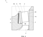
- Figure 3 is a schematic enlarged cross-sectional view showing the deformation mode of the vane plate 8 of a turbine T that does not include an inclined surface S when the vane plate 8 is heated.
- the turbine T of Figure 3 and Figure 4 below does not have an inclined surface S, as described below. Also, in Figures 3 and 4, the deformation of the vane plate 8 is exaggerated for better understanding.
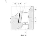
- Figure 4 is a schematic enlarged cross-sectional view showing the deformation mode of the vane plate 8 of a turbine T that does not include an inclined surface S when the vane plate 8 is cooled.
- the turbocharger 100 when the turbocharger 100 is cooled, cooling air flows through the connecting passage 62.
- the first surface 81 of the vane plate 8 that faces the connecting passage 62 becomes colder than the second surface 82 on the opposite side. Therefore, the first surface 81 contracts radially inward more than the second surface 82.
- the vane V tilts together with the vane plate 8. In this deformation mode, the innermost diameter part of the tip Va of the vane V moves away from the first wall surface W1, and a clearance is formed between the vane V and the first wall surface W1. Therefore, the efficiency of the turbine T1 decreases.
- an inclined surface S is formed on the first wall surface W1 in order to suppress the clearance formed by the deformation of the vane plate 8 as described above.
- the inclined surface S is formed in a direction that suppresses the clearance between the vane V and the first wall surface W1.
- the inclined surface S is formed on the first wall surface W1 so as to be inclined in a direction approaching the outermost diameter portion of the tip Va in a state without thermal deformation.
- the inclined surface S in a cross section parallel to and including the central axis, has a linear shape.
- the inclined surface S is formed so as to overlap the entire length of the tip Va in the radial direction.
- the angle of the inclined surface S with respect to the radial direction may be determined based on the amount of deformation of the vane plate 8 when the vane plate 8 is heated under a specified operating condition.
- the amount of deformation of the vane plate 8 may be determined by analysis or experiment.
- Figure 5 is a schematic enlarged cross-sectional view showing the behavior of the vanes V when the vane plate 8 in Figure 2 is heated. In Figure 5, the deformation of the vane plate 8 is also exaggerated for better understanding.
- the vane plate 8 when the vane plate 8 is heated, the vane plate 8 deforms so that the outermost diameter portion of the tip Va of the vane V moves away from the first wall surface W1.
- the inclined surface S is formed on the first wall surface W1 so as to be inclined in a direction approaching the outermost diameter portion of the tip Va. Therefore, the tip Va of the vane V moves to a position parallel to the inclined surface S. As a result, the contact area between the tip Va and the inclined surface S increases, and the clearance between the vane V and the first wall surface W1 is reduced.
- the inclined surface S may be formed in a direction that reduces the clearance between the vane V and the first wall surface W1 when the vane plate 8 is cooled (the situation shown in FIG. 4).
- the inclined surface S is formed on the first wall surface W1 so as to be inclined in a direction away from the outermost diameter portion of the tip Va.
- the turbine T1 includes a turbine impeller 3, a plurality of vanes V arranged circumferentially in a region radially outward of the turbine impeller 3 and protruding in the axial direction, a first wall surface W1 facing the tip Va of each of the vanes V in the axial direction, and an inclined surface S formed on the first wall surface W1 and inclined relative to the radial direction.
- the turbine T1 is also provided with an annular vane plate 8 that is disposed radially outward of the turbine impeller 3 and includes a first surface 81 facing the axial direction and a second surface 82 opposite the first surface 81, and the vanes V are provided with a vane plate 8 that protrudes from the first surface 81 of the vane plate 8, a second wall surface W2 that faces the first wall surface W1 in the axial direction between the vane plate 8 and the vanes V, and the second wall surface W2 that faces the second surface 82 of the vane plate 8, and an elastic body 9 that is disposed between the second surface 82 of the vane plate 8 and the second wall surface W2 and presses the vane plate 8 and the vanes V toward the first wall surface W1.
- the elastic body 9 can firmly press the tip Va of the vane V against the inclined surface S.
- FIG. 6 is a schematic enlarged cross-sectional view of the turbine T2 according to the second embodiment.
- the vane plate 8 and vanes V before thermal deformation are shown in solid lines, and the vane plate 8 and vanes V after thermal deformation are shown in dashed lines.
- the deformation of the vane plate 8 is exaggerated for better understanding.
- the turbine T2 according to this embodiment differs from the turbine T1 according to the first embodiment in that the inclined surface S is formed on the tip Va of the vane V instead of on the first wall surface W1.
- the turbine T2 may be the same as the turbine T1.
- the inclined surface S when the vane plate 8 is heated, the inclined surface S is formed in a direction that suppresses the clearance between the vane V and the first wall surface W1.
- the inclined surface S is formed on the tip Va such that the outermost diameter portion of the tip Va protrudes axially toward the first wall surface W1 more than the innermost diameter portion.
- the inclined surface S is formed over the entire length of the tip Va in the radial direction.
- the inclined surface S may be formed only on a portion of the tip Va in the radial direction.
- the inclined surface S may be formed only on the radially inner region of the tip Va. In this case, the remainder of the tip Va may be parallel or approximately parallel to the first wall surface W1 in a state without thermal deformation.
- the turbine T2 when the vane plate 8 is heated, the inclined surface S of the vane V moves to a position parallel to the first wall surface W1. As a result, as shown by the vane V in dashed lines, the contact area between the inclined surface S of the tip Va and the first wall surface W1 increases, and the clearance between the vane V and the first wall surface W1 is reduced. Therefore, the turbine T2 achieves substantially the same effects as the turbine T1 according to the first embodiment.
- FIG. 7 is a schematic enlarged cross-sectional view of a turbine T3 according to a third embodiment.
- the turbine T3 according to this embodiment differs from the turbine T1 according to the first embodiment in that the arrangement of the vane plate 8 and the vanes V is upside down in the axial direction compared to FIGS. 2 to 6, and the inclined surface S is formed in the turbine housing 6 instead of the bearing housing 5. Therefore, in this embodiment, a groove 51 that accommodates the vane plate 8 and the elastic body 9 is formed in the bearing housing 5.
- the turbine T3 may be the same as the turbine T1.
- the first wall surface W1 facing the tip Va of the vane V is the surface closest to the discharge port 61 among a pair of surfaces facing each other in the axial direction across the connecting flow passage 62.
- the first wall surface W1 is formed on the turbine housing 6.
- the second wall surface W2 facing the second surface 82 of the vane plate 8 is the surface farther from the discharge port 61 among a pair of surfaces facing each other in the axial direction across the connecting flow passage 62.
- the second wall surface W2 is formed on the bearing housing 5.
- the second wall surface W2 is the surface that defines the groove 51.
- the second wall surface W2 defines the groove 51 in the axial direction.
- the inclined surface S is formed in a direction that suppresses the clearance between the vane V and the first wall surface W1.
- an engine not shown
- hot exhaust gas from the engine flows through the connecting passage 62.
- the first surface 81 of the vane plate 8 that faces the connecting passage 62 becomes hotter than the second surface 82 on the opposite side. Therefore, as shown by the dashed line of the vane plate 8, the first surface 81 expands radially outward more than the second surface 82.
- the inclined surface S is formed on the first wall surface W1 so that, in a state without thermal deformation, it is inclined in a direction approaching the outermost diameter portion of the tip Va of the vane V.
- the inclined surface S is formed so as to overlap the entire length of the tip Va in the radial direction.
- the inclined surface S may be formed in a direction that suppresses the clearance between the vane V and the first wall surface W1 when the vane plate 8 is cooled.
- the inclined surface S is formed on the first wall surface W1 so that it is inclined in a direction away from the outermost diameter portion of the tip Va of the vane V in a state without thermal deformation.
- the turbine T3 when the vane plate 8 is heated, the tip Va of the vane V moves to a position parallel to the inclined surface S. As a result, the contact area between the tip Va and the inclined surface S increases, and the clearance between the vane V and the first wall surface W1 is reduced. Therefore, the turbine T3 achieves substantially the same effects as the turbine T1 according to the first embodiment.
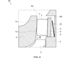
- FIG. 8 is a schematic enlarged cross-sectional view of the turbine T4 according to the fourth embodiment.
- the turbine T4 according to this embodiment differs from the turbine T3 according to the third embodiment in that the inclined surface S is shorter in the radial direction. In other respects, the turbine T4 may be the same as the turbine T3.
- the inclined surface S overlaps only a portion of the tip Va in the radial direction. In this embodiment, the inclined surface S overlaps only the radially inner region of the tip Va.
- the first wall surface W1 includes a surface that is radially outward from the inclined surface S and parallel to the radial direction.
- the tip Va of the vane V moves to a position parallel to the inclined surface S.
- the radially inner region of the tip Va is pressed against the inclined surface S. Therefore, the clearance between the vane V and the first wall surface W1 is reduced compared to when only the innermost diameter portion of the tip Va is pressed against the first wall surface W1.
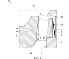
- FIG. 9 is a schematic enlarged cross-sectional view of the turbine T5 according to the fifth embodiment.
- the turbine T5 according to this embodiment differs from the turbine T3 according to the third embodiment in that a discontinuous portion 65 is formed in the first wall surface W1.
- the turbine T5 may be the same as the turbine T3. Note that the axial height of the discontinuous portion 65 is exaggerated.
- the discontinuous portion 65 protrudes from the inclined surface S in a generally axial direction.
- the discontinuous portion 65 is located radially inward relative to the tip Va of the vane V.
- the discontinuous portion 65 may be continuous in the circumferential direction.
- the discontinuous portion 65 is smoothly connected to the shroud 66 and is continuous with the shroud 66.
- the turbine T5 according to this embodiment as described above has substantially the same effects as the turbine T3 according to the third embodiment.
- the inclined surface S is formed on the first wall surface W1, which is located radially inward relative to the tip Va of the vane V and includes a discontinuous portion 65 that protrudes from the inclined surface S. With this configuration, the vane V is positioned deep relative to the discontinuous portion 65, thereby reducing the gap at the tip Va of the vane V.
- the rotating device is a turbine T1, T2, T3, T4, or T5, and the inclined surface S is formed on a vane V arranged in the connecting passage 62 or on a wall surface defining the connecting passage 62.
- the rotating device may be a centrifugal compressor C, and the inclined surface S may be formed on a diffuser vane arranged in the diffuser passage 72 or on a wall surface defining the diffuser passage 72.
- the rotating device includes an elastic body 9.
- the rotating device may not include an elastic body 9.
- the rotating device may not include a vane plate 8, and the vanes V may protrude directly from the wall surface that defines the flow path in which the vanes V are arranged.
- the inclined surface S is formed on one of the first wall surface W1 and the tip Va of the vane V.
- the inclined surface S may be formed on both the first wall surface W1 and the tip Va of the vane V.
- the angle of the inclined surface S may be determined so that the sum of the absolute value of the angle of the inclined surface S formed on the first wall surface W1 relative to the radial direction and the absolute value of the angle of the inclined surface S formed on the tip Va relative to the radial direction corresponds to the deformation amount of the vane plate 8.
- the inclined surface S formed on the first wall surface W1 and the inclined surface S formed on the tip Va are inclined in opposite directions relative to the radial direction.
- the inclined surface S may be formed on the first wall surface W1 so as to be half the angle shown in FIG. 2, and the inclined surface S may be formed on the tip Va so as to be half the angle shown in FIG. 6.
- Turbine impeller 4 Compressor impeller 8: Vane plate 9: Elastic body 65: Discontinuous portion 81: First surface 82: Second surface C: Centrifugal compressor (rotating device) S Inclined surface T1 Turbine (rotating device) T2 Turbine (rotating device) T3 Turbine (rotating device) T4 Turbine (rotating device) T5 Turbine (rotating device) V Vane Va Tip of vane W1 First wall W2 Second wall
Landscapes
- Engineering & Computer Science (AREA)
- Mechanical Engineering (AREA)
- General Engineering & Computer Science (AREA)
- Chemical & Material Sciences (AREA)
- Combustion & Propulsion (AREA)
- Supercharger (AREA)
Priority Applications (4)
| Application Number | Priority Date | Filing Date | Title |
|---|---|---|---|
| CN202480027724.7A CN121013940A (zh) | 2023-06-22 | 2024-03-07 | 旋转装置 |
| JP2025527459A JPWO2024262099A1 (https=) | 2023-06-22 | 2024-03-07 | |
| DE112024001434.8T DE112024001434T5 (de) | 2023-06-22 | 2024-03-07 | Rotationsvorrichtung |
| US19/359,235 US20260043418A1 (en) | 2023-06-22 | 2025-10-15 | Rotation device |
Applications Claiming Priority (2)
| Application Number | Priority Date | Filing Date | Title |
|---|---|---|---|
| JP2023102413 | 2023-06-22 | ||
| JP2023-102413 | 2023-06-22 |
Related Child Applications (1)
| Application Number | Title | Priority Date | Filing Date |
|---|---|---|---|
| US19/359,235 Continuation US20260043418A1 (en) | 2023-06-22 | 2025-10-15 | Rotation device |
Publications (1)
| Publication Number | Publication Date |
|---|---|
| WO2024262099A1 true WO2024262099A1 (ja) | 2024-12-26 |
Family
ID=93935313
Family Applications (1)
| Application Number | Title | Priority Date | Filing Date |
|---|---|---|---|
| PCT/JP2024/008777 Ceased WO2024262099A1 (ja) | 2023-06-22 | 2024-03-07 | 回転装置 |
Country Status (5)
| Country | Link |
|---|---|
| US (1) | US20260043418A1 (https=) |
| JP (1) | JPWO2024262099A1 (https=) |
| CN (1) | CN121013940A (https=) |
| DE (1) | DE112024001434T5 (https=) |
| WO (1) | WO2024262099A1 (https=) |
Citations (7)
| Publication number | Priority date | Publication date | Assignee | Title |
|---|---|---|---|---|
| JPS6361545U (https=) * | 1986-10-09 | 1988-04-23 | ||
| JPH07259796A (ja) * | 1994-03-18 | 1995-10-09 | Hitachi Ltd | 遠心圧縮機 |
| JP2005320970A (ja) * | 2004-05-06 | 2005-11-17 | Cummins Inc | 可変幾何学的形態タービンを使用する内燃機関におけるあと処理システム用の排ガスの温度を決定する方法 |
| WO2009046504A1 (en) * | 2007-10-09 | 2009-04-16 | Atlas Copco Airpower, Naamloze Vennootschap | Improved turbo-compressor |
| WO2012036122A1 (ja) * | 2010-09-13 | 2012-03-22 | 株式会社Ihi | 固定翼式ターボチャージャ |
| WO2014102962A1 (ja) * | 2012-12-27 | 2014-07-03 | 三菱重工業株式会社 | 可変容量型排気ターボ過給機 |
| WO2016031017A1 (ja) * | 2014-08-28 | 2016-03-03 | 三菱重工業株式会社 | 膨張タービン及びターボチャージャ |
-
2024
- 2024-03-07 JP JP2025527459A patent/JPWO2024262099A1/ja active Pending
- 2024-03-07 CN CN202480027724.7A patent/CN121013940A/zh active Pending
- 2024-03-07 WO PCT/JP2024/008777 patent/WO2024262099A1/ja not_active Ceased
- 2024-03-07 DE DE112024001434.8T patent/DE112024001434T5/de active Pending
-
2025
- 2025-10-15 US US19/359,235 patent/US20260043418A1/en active Pending
Patent Citations (7)
| Publication number | Priority date | Publication date | Assignee | Title |
|---|---|---|---|---|
| JPS6361545U (https=) * | 1986-10-09 | 1988-04-23 | ||
| JPH07259796A (ja) * | 1994-03-18 | 1995-10-09 | Hitachi Ltd | 遠心圧縮機 |
| JP2005320970A (ja) * | 2004-05-06 | 2005-11-17 | Cummins Inc | 可変幾何学的形態タービンを使用する内燃機関におけるあと処理システム用の排ガスの温度を決定する方法 |
| WO2009046504A1 (en) * | 2007-10-09 | 2009-04-16 | Atlas Copco Airpower, Naamloze Vennootschap | Improved turbo-compressor |
| WO2012036122A1 (ja) * | 2010-09-13 | 2012-03-22 | 株式会社Ihi | 固定翼式ターボチャージャ |
| WO2014102962A1 (ja) * | 2012-12-27 | 2014-07-03 | 三菱重工業株式会社 | 可変容量型排気ターボ過給機 |
| WO2016031017A1 (ja) * | 2014-08-28 | 2016-03-03 | 三菱重工業株式会社 | 膨張タービン及びターボチャージャ |
Also Published As
| Publication number | Publication date |
|---|---|
| DE112024001434T5 (de) | 2026-01-15 |
| JPWO2024262099A1 (https=) | 2024-12-26 |
| CN121013940A (zh) | 2025-11-25 |
| US20260043418A1 (en) | 2026-02-12 |
Similar Documents
| Publication | Publication Date | Title |
|---|---|---|
| EP2180160B1 (en) | Turbo charger | |
| US7351042B2 (en) | Structure of scroll of variable-throat exhaust turbocharger and method for manufacturing the turbocharger | |
| EP3904693B1 (en) | Centrifugal compressor and air conditioning apparatus | |
| JP6542246B2 (ja) | 可変容量型過給機 | |
| US9103223B2 (en) | Shaft sealing device and rotating machine comprising same | |
| JPS6237214B2 (https=) | ||
| WO2015190470A1 (ja) | 可変ノズルユニット及び可変容量型過給機 | |
| JP2013253521A (ja) | 可変ノズルユニット及び可変容量型過給機 | |
| US11459907B2 (en) | Variable capacity turbocharger | |
| JP2012107527A (ja) | ターボチャージャ | |
| JP7315109B2 (ja) | 過給機 | |
| CN116670381B (zh) | 增压器 | |
| CN103806948B (zh) | 涡轮增压器和用于它的可变喷嘴筒体 | |
| WO2024262099A1 (ja) | 回転装置 | |
| JP6969670B2 (ja) | 過給機 | |
| JP2013253520A (ja) | 可変ノズルユニット及び可変容量型過給機 | |
| JP6146507B2 (ja) | 可変ノズルユニット及び可変容量型過給機 | |
| WO2024237107A1 (ja) | 回転装置 | |
| CN212615553U (zh) | 轴承壳体、壳体组件和涡轮增压器 | |
| JPWO2019077962A1 (ja) | 過給機のシール構造 | |
| JP2024164896A (ja) | 回転装置 | |
| WO2025052734A1 (ja) | 回転装置 | |
| JP7651986B2 (ja) | 遠心式回転装置 | |
| CN114981528B (zh) | 可变容量型增压器 | |
| JP7643214B2 (ja) | 遠心式回転装置 |
Legal Events
| Date | Code | Title | Description |
|---|---|---|---|
| 121 | Ep: the epo has been informed by wipo that ep was designated in this application |
Ref document number: 24825510 Country of ref document: EP Kind code of ref document: A1 |
|
| ENP | Entry into the national phase |
Ref document number: 2025527459 Country of ref document: JP Kind code of ref document: A |
|
| WWE | Wipo information: entry into national phase |
Ref document number: 2025527459 Country of ref document: JP |
|
| WWE | Wipo information: entry into national phase |
Ref document number: 112024001434 Country of ref document: DE |
|
| WWP | Wipo information: published in national office |
Ref document number: 112024001434 Country of ref document: DE |