WO2024261874A1 - シミュレーションシステム及びシミュレーション方法 - Google Patents
シミュレーションシステム及びシミュレーション方法 Download PDFInfo
- Publication number
- WO2024261874A1 WO2024261874A1 PCT/JP2023/022792 JP2023022792W WO2024261874A1 WO 2024261874 A1 WO2024261874 A1 WO 2024261874A1 JP 2023022792 W JP2023022792 W JP 2023022792W WO 2024261874 A1 WO2024261874 A1 WO 2024261874A1
- Authority
- WO
- WIPO (PCT)
- Prior art keywords
- types
- virtual
- simulation
- controllers
- copy
- Prior art date
- Legal status (The legal status is an assumption and is not a legal conclusion. Google has not performed a legal analysis and makes no representation as to the accuracy of the status listed.)
- Ceased
Links
Images


Classifications
-
- B—PERFORMING OPERATIONS; TRANSPORTING
- B25—HAND TOOLS; PORTABLE POWER-DRIVEN TOOLS; MANIPULATORS
- B25J—MANIPULATORS; CHAMBERS PROVIDED WITH MANIPULATION DEVICES
- B25J13/00—Controls for manipulators
-
- G—PHYSICS
- G05—CONTROLLING; REGULATING
- G05B—CONTROL OR REGULATING SYSTEMS IN GENERAL; FUNCTIONAL ELEMENTS OF SUCH SYSTEMS; MONITORING OR TESTING ARRANGEMENTS FOR SUCH SYSTEMS OR ELEMENTS
- G05B19/00—Program-control systems
- G05B19/02—Program-control systems electric
- G05B19/418—Total factory control, i.e. centrally controlling a plurality of machines, e.g. direct or distributed numerical control [DNC], flexible manufacturing systems [FMS], integrated manufacturing systems [IMS] or computer integrated manufacturing [CIM]
Definitions
- This disclosure relates to a simulation system and a simulation method.
- Patent Document 1 discloses a simulation device that includes a first simulator that simulates control of a first machine by a first controller, a second simulator that simulates control of a second machine by a second controller, and a simulation manager that controls the progress of the simulation by the first simulator and the progress of the simulation by the second simulator so as to correspond to the relationship between the progress of the control by the first controller and the progress of the control by the second controller.
- the present disclosure provides a system that is effective in improving engineering efficiency for cells.
- a simulation system is a system for simulating a cell having multiple types of machines and multiple types of controllers that cause the multiple types of machines to cooperate with each other, and includes a simulation environment that causes multiple types of virtual controllers corresponding to the multiple types of controllers to simulate cooperation, and multiple types of user interfaces that are accessible to each of the multiple types of virtual controllers in the simulation environment, differ from one another depending on the type of the corresponding virtual controller, and are specialized for engineering the corresponding virtual controller.
- a simulation system is a system for simulating a cell having multiple types of machines and multiple types of controllers that cause the multiple types of machines to cooperate with each other, and includes multiple types of user interfaces that are accessible to each of the multiple types of controllers and differ from one another depending on the type of the corresponding controller, and that are specialized for the engineering of the corresponding controller, a virtual space generation unit that causes the multiple types of machines to further cooperate in a virtual space based on the control results of the multiple types of machines by the multiple types of controllers, and a virtual space display unit that displays the virtual space in which the multiple types of machines are operating in cooperation based on the control results on at least one user interface that is accessing the corresponding controller.
- a simulation method is a method for simulating a cell having multiple types of machines and multiple types of controllers that cause the multiple types of machines to cooperate with each other, the method including: in a simulation environment including multiple types of virtual controllers respectively corresponding to the multiple types of controllers, causing the multiple types of virtual controllers to access multiple types of user interfaces that differ depending on the type of the corresponding virtual controller and that are specialized for the engineering of the corresponding virtual controller; updating the multiple types of virtual controllers based on input to the multiple types of user interfaces; and simulating cooperation of the updated multiple types of virtual controllers in the simulation environment.
- the present disclosure provides a system that is effective in improving the engineering efficiency of cells.
- FIG. 1 is a schematic diagram illustrating a configuration of a production system.
- FIG. 2 is a schematic diagram illustrating a configuration of a robot.
- FIG. 2 is a block diagram illustrating a functional configuration of the simulation system.
- FIG. 13 is a block diagram showing a modified example of the simulation system.
- FIG. 13 is a block diagram showing a further modified example of the simulation system.
- FIG. 13 is a block diagram showing a further modified example of the simulation system.
- FIG. 13 is a block diagram showing a further modified example of the simulation system.
- FIG. 13 is a block diagram showing a further modified example of the simulation system.
- FIG. 13 is a block diagram showing a further modified example of the simulation system.
- FIG. 13 is a block diagram showing a further modified example of the simulation system.
- FIG. 13 is a block diagram showing a further modified example of the simulation system.
- FIG. 13 is a block diagram showing a further modified example of the simulation system.
- FIG. 13 is
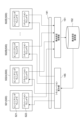
- the production system 1 shown in Figure 1 is a system that produces products in real space.
- the products can be any tangible object that is produced by mechanically processing and assembling one or more parts.
- the real space is the space in which tangible objects actually exist.
- the production system 1 includes a cell 2 and a control system 3.
- the cell 2 executes a processing step on a workpiece W in real space to produce a product.
- the workpiece W is a tangible object that the cell 2 handles to form at least a part of the product.
- the workpiece W may be a part to be assembled into the product, an intermediate product formed by assembling parts, or the final completed product itself.
- the processing steps for the workpiece W include multiple tasks.
- a task is a set of operations with a predetermined sequence for a specific work purpose. At least one of the multiple tasks can be shared by two or more different processing steps. The execution sequence of the multiple tasks can be changed depending on the content of the processing step, but the sequence of operations within one task cannot be changed. Examples of multiple tasks include carrying a base part into the work area, assembling a part to the base part, fastening or welding the part to the base part, assembling one or more parts to the base part, and carrying the completed product out of the work area.
- the cell 2 includes multiple machines 5.
- the multiple machines 5 include two or more machines 5 of different types. Different types means that the platforms for creating control programs are different due to differences in structure, for example.
- the multiple machines 5 may include a robot and a machine of a different type from the robot. Examples of machines of a different type from the robot include, but are not limited to, a transport device that transports the workpiece W, a device that adjusts the position and posture of the workpiece W that is the subject of the robot's work, and a machine tool that processes the workpiece W. Any structure can be included in the multiple machines 5 as long as it is capable of executing a task on the workpiece W.
- the multiple tasks may include two or more tasks that should be executed sequentially in series, or may include two or more tasks that can be executed simultaneously by multiple machines 5.
- Examples of tasks executed by a robot include transporting the workpiece W, assembling the workpiece W, fixing the workpiece W (e.g., fastening or welding), and carrying the workpiece W into and out of a surrounding machine such as a machine tool.
- Examples of tasks executed by a machine tool include opening and closing doors, chucking the carried-in workpiece W, rotating and moving the workpiece W, changing tools, placing and moving tools relative to the workpiece W, and releasing the chuck after processing.
- the multiple machines 5 shown in FIG. 1 include, as two or more machines 5 of different types, a conveying device 5A, robots 5B and 5C, a robot 5D, and a machine tool 5E, but are not limited to this. As long as at least two or more machines 5 of different types are included, the number and types of machines 5 can be changed in any way.
- the conveying device 5A is driven, for example, by an electric motor, and conveys the workpiece W.
- Examples of the conveying device 5A include a belt conveyor, a roller conveyor, a carousel, etc.
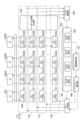
- Robots 5B and 5C are vertical articulated robots, and as shown in FIG. 2, have an articulated arm 10 and an end effector 50.
- the end effector 50 acts on the workpiece W.
- Examples of the end effector 50 include a hand that holds the workpiece W, a suction nozzle that picks up the workpiece W, a welding torch that welds the workpiece W, or a screw tightening tool that tightens screws on the workpiece W.
- the multi-joint arm 10 is connected to the end effector 50, and changes the position and posture of the end effector 50 by the operation of the multi-joint.
- the multi-joint arm 10 has a base 11, a rotating part 12, a first arm 13, a second arm 14, a swinging part 15, a third arm 17, a tip 18, and actuators 41, 42, 43, 44, 45, and 46.
- the base 11 is installed around the conveying device 5A.
- the rotating part 12 is provided on the base 11 so as to swing around a vertical axis 21.
- the first arm 13 is connected to the rotating part 12 so as to swing around an axis 22 that intersects (for example, perpendicular to) the axis 21.
- the intersection also includes a case where there is a twisted relationship, such as a so-called three-dimensional intersection.
- the second arm 14 is connected to the tip of the first arm 13 so as to swing around an axis 23 that is substantially parallel to the axis 22.
- the second arm 14 includes a swinging part 15 and a rotating part 16.
- the swinging part 15 is connected to the tip of the first arm 13 and extends along an axis 24 that intersects (e.g., perpendicular to) the axis 23.
- the rotating part 16 is connected to the tip of the swinging part 15 so as to rotate around the axis 24, and further extends along the axis 24.
- the third arm 17 is connected to the tip of the rotating part 16 so as to swing around an axis 25 that intersects (e.g., perpendicular to) the axis 24.
- the tip 18 is connected to the tip of the third arm 17 so as to rotate around an axis 26 that intersects (e.g., perpendicular to) the axis 25.
- a work tool such as a hand, a suction nozzle, or a welding torch is attached to the tip 18.
- the multi-joint arm 10 has a joint 31 connecting the base 11 and the swivel 12, a joint 32 connecting the swivel 12 and the first arm 13, a joint 33 connecting the first arm 13 and the second arm 14, a joint 34 connecting the swinging part 15 and the swivel 16 in the second arm 14, a joint 35 connecting the swivel 16 and the third arm 17, and a joint 36 connecting the third arm 17 and the tip 18.
- Actuators 41, 42, 43, 44, 45, and 46 include, for example, electric motors and reducers, and drive joints 31, 32, 33, 34, 35, and 36, respectively.
- actuator 41 rotates rotating part 12 around axis 21
- actuator 42 swings first arm 13 around axis 22
- actuator 43 swings second arm 14 around axis 23
- actuator 44 rotates rotating part 16 around axis 24
- actuator 45 swings third arm 17 around axis
- actuator 46 swings tip 18 around axis 26.
- the configuration of the multi-joint arm 10 can be changed as appropriate.
- the multi-joint arm 10 may be a seven-axis redundant robot in which an additional joint is added to the six-axis configuration described above, or may be a so-called SCARA type multi-joint robot.
- robot 5D is an autonomous robot.
- robot 5D is a robot similar to robots 5B and 5C, in which the base 11 of the articulated arm 10 is capable of self-propelling.
- An example of a self-propelled base 11 is an electric automated guided vehicle (AGV).
- AGV electric automated guided vehicle
- the machine tool 5E performs cutting and other processes on the workpiece W that is carried in and out by the robots 5B and 5C.
- Examples of the machine tool 5E include an NC lathe, an NC milling machine, and a machining center.
- the cell 2 may further include a peripheral device whose range of motion overlaps with any of the robots 5B, 5C, and 5D.
- the range of motion of the robot 5C may overlap with the robot 5B.
- the production system 1 may further include one or more environmental sensors 6.
- the environmental sensor 6 include a presence sensor provided at a position where the workpiece W can be placed, or a camera that photographs the position where the workpiece W can be placed.
- the environmental sensor 6 is, for example, a camera or an optical three-dimensional shape sensor, and acquires status information of at least a portion of the environment including the multiple machines 5 and objects surrounding the multiple machines 5.
- the environmental sensor 6 may be a presence sensor that detects whether or not the workpiece W is present at a position where the workpiece W can be placed.
- the control system 3 controls the multiple machines 5 to execute production corresponding to a production plan generated by, for example, a manufacturing execution system (MES).
- MES manufacturing execution system
- the control system 3 includes multiple controllers 300, a data collection device 200, and a simulation device 100.
- the multiple controllers 300 cause the multiple machines 5 to cooperate with each other. To cause the multiple machines 5 to cooperate with each other, each of the multiple controllers 300 executes its own process based on a predetermined control program.
- the multiple controllers 300 include a local controller 302 that controls each of the multiple machines 5, and a host controller 301. Each of the multiple local controllers 302 controls the corresponding machine 5 based on a predetermined local control program.
- the host controller 301 performs synchronous communication with the multiple local controllers 302. Synchronous communication means that communication with the multiple local controllers 302 is performed for each period in synchronization with a synchronization frame of a fixed communication cycle.
- the host controller 301 aggregates information obtained from the multiple local controllers 302 through synchronous communication to update the environmental information, and sequentially assigns tasks to each of the multiple local controllers 302 based on a predetermined host control program and the environmental information.
- the host controller 301 may also update the environmental information based on the detection results from the environmental sensor 6.
- the local control program of each of the multiple local controllers 302 includes one or more task programs for causing the machine 5 to execute one or more tasks that can be assigned by the host controller 301.
- Each of the multiple local controllers 302 executes a task program corresponding to a task assigned by the host controller 301, thereby causing the corresponding machine 5 to execute the assigned task.
- each of the multiple local controllers 302 may select and execute one or more task programs based on a comparison of the execution conditions of the one or more task programs with environmental information.
- the multiple controllers 300 may include two or more controllers 300 of different types. Different types include different platforms for creating control programs. For example, the host controller 301 and the local controller 302 may be of different types. For example, the platform for creating the local control program and the platform for creating the host control program may be different.
- the multiple local controllers 302 may include two or more local controllers 302 of different types.
- the multiple local controllers 302 in FIG. 1 include local controller 302A that controls the transport device 5A, local controllers 302B, 302C, and 302D that control robots 5B, 5C, and 5D, and local controller 302E that controls the machine tool 5E.
- the platform for creating the local control program for local controller 302A, the platform for creating the local control programs for local controllers 302B, 302C, and 302D, and the platform for creating the local control program for local controller 302E are different from each other.
- the platforms for creating the local control programs for local controllers 302B and 302C that control robots 5B and 5C and local controller 302D that controls autonomously traveling robot 5D may be different from each other.
- a platform for creating local control programs for local controllers 302B and 302C may be a platform based on a robot programming language.
- An example of a platform for creating a host control program for host controller 301 may be a platform based on a ladder language.
- the data collection device 200 communicates with the host controller 301 via a network, for example, and accumulates environmental information updated by the host controller 301 in a database in chronological order.
- the simulation device 100 simulates the cell 2. Simulating the cell 2 means operating the cell 2 in a virtual space instead of operating the cell 2 in a real space.
- Engineering includes setting of control parameters, creation and editing of control programs, etc.
- Engineering for the multiple controllers 300 is performed by multiple types of user interfaces that can access each of the multiple controllers 300, differ depending on the type of the corresponding controller 300, and are specialized for engineering of the corresponding controller 300. Therefore, engineering can be performed by collaboration between multiple users who have different skills (for example, platforms for which programming skills are available).
- the simulation device 100 is configured to use the simulation of the cell 2 to perform engineering for multiple controllers 300 in a virtual space.
- one or more user interfaces for engineering are connected to the simulation device 100.
- a simulation system including one or more user interfaces for engineering and the simulation device 100 will be described.
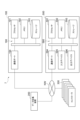
- the simulation system 7 includes a simulation device 100 and a plurality of user interfaces 500.
- the simulation device 100 has a simulation environment 101.
- the simulation environment 101 includes a plurality of virtual controllers 120 corresponding to the plurality of controllers 300, respectively, and causes the plurality of virtual controllers 120 to simulate the above-mentioned cooperation of the plurality of machines 5.
- the simulation performed by the plurality of virtual controllers 120 includes estimating, by calculation, a phenomenon that is generated in real space by the plurality of controllers 300.
- the phenomenon that is generated by the plurality of controllers 300 includes operating actuators such as the actuators 41, 42, 43, 44, 45, 46, and communicating information between the plurality of controllers 300.
- the multiple virtual controllers 120 also include two or more virtual controllers 120 of different types.
- the multiple virtual controllers 120 include a virtual host controller 121 corresponding to the host controller 301 and a multiple virtual local controllers 122 corresponding to the multiple local controllers 302, respectively.
- the multiple virtual local controllers 122 include a multiple virtual local controllers 122A-122E corresponding to the multiple local controllers 302A-302E, respectively.
- the multiple virtual local controllers 122 also include two or more virtual local controllers 122 of different types.
- the multiple user interfaces 500 are respectively accessible to the multiple virtual controllers 120 of the simulation environment 101.
- Each of the multiple user interfaces 500 is specialized for the engineering of the corresponding virtual controller 120.
- Two or more user interfaces 500 corresponding to two or more virtual controllers 120 of different types differ from each other depending on the types of the corresponding virtual controllers 120.
- the multiple user interfaces 500 include a user interface 501 specialized for the engineering of the virtual host controller 121, and multiple user interfaces 502 specialized for the engineering of the multiple virtual local controllers 122.
- the multiple user interfaces 502 include user interfaces 502A to 502E specialized for the engineering of the virtual local controllers 122A to 122E, respectively.
- Simulation system 7 allows engineering of multiple virtual controllers 120 to be performed individually using a user interface 500 specialized for engineering of the corresponding virtual controller 120, similar to engineering of multiple controllers 300. Therefore, engineering performed collaboratively by multiple users with different skills can be performed in a simulation environment separate from the construction of the cell 2 hardware. Moreover, in the simulation environment, trial and error can be repeated in short cycles even when the engineering is still at a low level of completion. This improves the efficiency of engineering for cell 2.
- Each of the multiple user interfaces 500 is configured by executing a user interface program in hardware such as a terminal device.
- the terminal device may be a general-purpose device such as a laptop computer, tablet computer, or smartphone, or may be a terminal device specialized for engineering (e.g., a programming pendant for a robot controller).
- the fact that the two or more user interfaces 500 are different from one another includes, for example, that the user inputs that can be accepted are different from one another, that the display differs depending on the differences in the user inputs that can be accepted, etc. It is also possible to use a common terminal device as two or more different user interfaces 500 by using two or more different user interface programs. In this case, it cannot be said that the terminal device itself is specialized for the engineering of one type of virtual controller 120, but each of the two or more user interfaces 500 configured by the terminal device executing two or more user interface programs is specialized for the engineering of one type of virtual controller 120.
- Multiple user interfaces 500 being able to access multiple virtual controllers 120 respectively includes at least one user interface 500 being able to access two or more virtual controllers 120 that are different from each other.
- the number of types of user interfaces 500 and the number of types of virtual controllers 120 are different.
- the multiple user interfaces 500 may be accessible to the multiple controllers 300, respectively.
- the multiple user interfaces 500 may be shared for engineering the multiple controllers 300 and engineering the multiple virtual controllers 120, but they do not necessarily have to be shared.
- the multiple user interfaces 500 for engineering the multiple controllers 300 may be provided separately for engineering the multiple virtual controllers 120.
- the communication interface between the multiple user interfaces 500 and the multiple controllers 300 and the communication interface between the multiple user interfaces 500 and the multiple virtual controllers 120 may be common.
- the communication protocol between the multiple user interfaces 500 and the multiple controllers 300 and the communication protocol between the multiple user interfaces 500 and the multiple virtual controllers 120 may be common.
- the efficiency of engineering in the virtual environment is further improved. For example, when updating the results of engineering in the virtual environment with further engineering in the real environment, the common user interface allows work to continue smoothly.
- the simulation device 100 may further include an access management unit 141.
- the access management unit 141 allows the multiple user interfaces 500 to access the multiple virtual controllers 120 independently of each other. For example, when one user interface 500 is connected to the simulation device 100, the access management unit 141 identifies the virtual controller 120 corresponding to the one user interface 500, and allows the one user interface 500 to access the corresponding virtual controller 120 without allowing access to the other virtual controllers 120. Allowing one user interface 500 to access the corresponding virtual controller 120 includes establishing communication between the one user interface 500 and the corresponding virtual controller 120 (e.g., pairing).
- the access management unit 141 may assign unique identification information to each of the multiple virtual controllers 120, and may allow one user interface 500 to access the corresponding virtual controller 120 based on the identification information specified by one user interface 500.
- the access management unit 141 may assign a unique IP address to each of the multiple virtual controllers 120 as the identification information, or may assign a combination of a common IP address and a unique port number. Since access between one user interface 500 and the corresponding virtual controller 120 is independent of access between other user interfaces 500 and other virtual controllers 120, communication with an appropriate communication partner can be achieved. Even in a system that simulates the entire cell 2, each of the multiple user interfaces 500 accesses the corresponding virtual controller 120 without accessing the other virtual controllers 120. This allows each user to concentrate on the engineering of the corresponding virtual controller 120. In addition, access to each virtual controller 120 is limited to access from the corresponding user interface 500, which avoids confusion caused by overlapping engineering from two or more user interfaces 500 for one virtual controller 120.
- the simulation device 100 may have two or more communication ports to which two or more user interfaces 500 can be connected simultaneously.
- the access management unit 141 may parallelize two or more communications linking the two or more user interfaces 500 with two or more virtual controllers, respectively.
- the simulation device 100 may further include a model holding unit 142, a virtual space generating unit 143, a virtual space holding unit 144, and a virtual space display unit 145.
- the model holding unit 142 holds (stores) a system model including models of the multiple machines 5 and a model of the surrounding environment of the multiple machines 5.
- Each of the models of the multiple machines 5 is data representing the arrangement, structure, shape, size, etc. of the corresponding machine 5 in real space.
- the model of the surrounding environment of the multiple machines 5 is data representing the arrangement, structure, shape, size, etc. of surrounding objects (e.g., structures such as frames and one or more workpieces W) that constitute the surrounding environment of the multiple machines 5 in real space.
- the arrangement, structure, shape, and size in the system model are represented by, for example, polygon data or voxel data.
- the coordinate system based on the system model corresponds to the virtual space in which the multiple machines 5 and the surrounding environment of the multiple machines 5 are virtually arranged.
- the virtual space generation unit 143 causes the multiple machines 5 to cooperate in the virtual space based on the results of simulations performed by the multiple virtual controllers 120. For example, the virtual space generation unit 143 causes each of the multiple machines 5 to operate in the virtual space so as to cooperate, based on the actuator operations estimated by the simulations performed by the multiple virtual controllers 120 and the system model held by the model holding unit 142. For example, the virtual space generation unit 143 operates the models of robots 5B and 5C in the virtual space by forward kinematics calculations based on the operating angles of actuators 41, 42, 43, 44, 45, and 46 and the models of robots 5B and 5C.
- the virtual space holding unit 144 holds (stores) the collaboration that the virtual space holding unit 144 has the multiple machines 5 execute in the virtual space. For example, the virtual space holding unit 144 holds the change over time in the state (e.g., position, posture, etc.) of each of the multiple machines 5 during the execution of the collaboration.
- the virtual space display unit 145 displays the virtual space in which the multiple machines 5 are working together on at least one of the multiple user interfaces 500.
- the movements of the multiple machines 5 in the virtual space can be confirmed on each user interface. In this case, since it is possible to confirm the movements of not only the machine 5 corresponding to the virtual controller 120 that performed the engineering, but also the other machines 5, engineering efficiency is improved.
- each of the multiple user interfaces 500 has an engineering window 521 and a simulation window 522.
- the engineering window 521 includes one or more objects (such as buttons or input boxes) that accept user input in the above-mentioned engineering.
- the simulation window 522 displays a virtual space.
- the virtual space display unit 145 may display a virtual space in which the multiple machines 5 are working together in the simulation window 522 of each of the multiple user interfaces 500.
- the virtual space display unit 145 may display the virtual space from independent viewpoints on at least two or more of the multiple user interfaces 500 (e.g., two or more of different types). By adjusting the viewpoint for each of the multiple users, engineering efficiency in the virtual environment is further improved.
- the viewpoints that are independent of each other are viewpoints that are set independently of each other, for example, by a user's input.
- the simulation device 100 may further include a viewpoint setting acquisition unit 151 and a viewpoint setting storage unit 152.
- the viewpoint includes, for example, a position in the virtual space and a direction from that position.
- the simulation device 100 may further include a history storage unit 161.
- the history storage unit 161 stores the engineering history of the corresponding virtual controller 120 by each of the multiple user interfaces 500. By referring to the engineering history, the engineering status of the entire cell can be easily understood.
- the simulation device 100 may further include a messenger 171.
- the messenger 171 displays a message input to one user interface 500 on the other user interfaces 500.
- each of the multiple user interfaces 500 further includes a message window 523 in which a message can be input and displayed.
- the messenger 171 accumulates messages input to the message windows 523 of each of the multiple user interfaces 500 in chronological order, and displays the accumulated messages in the message windows 523, for example, in a chat format.
- the simulation device 100 may have a copy generation unit 181 as an example of having a simulation environment 101.
- the copy generation unit 181 When engineering a virtual controller 120 that corresponds to one of a plurality of user interfaces 500, the copy generation unit 181 generates a copy simulation environment 110 that corresponds to one user interface 500 as the simulation environment 101.
- having a simulation environment 101 is not limited to having the simulation environment 101 at all times, but also includes having a copy generation unit 181 that dynamically generates a copy simulation environment 110 as needed.
- the copy simulation environment 110 includes multiple virtual controllers 120.
- the access management unit 141 allows the above-mentioned one user interface 500 to access the corresponding virtual controller 120 in the copy simulation environment 110.
- One user can perform trial and error including engineering and simulation of a cell independently of other users. Therefore, the cell 2 can be constructed more efficiently.
- Figure 8 illustrates an example of engineering the virtual controllers 120 corresponding to the user interface 501 and the user interfaces 502A-502E.
- the copy generation unit 181 generates multiple copy simulation environments 111-116 corresponding to the user interface 501 and the user interfaces 502A-502E, respectively.
- the access management unit 141 allows the user interface 501 to access the virtual host controller 121 of the copy simulation environment 111, but does not allow the user interface 501 to access the virtual host controllers 121 of the user interfaces 502A-502E.
- the access management unit 141 allows the user interface 502A to access the virtual local controller 122A of the copy simulation environment 112, the user interface 502B to access the virtual local controller 122B of the copy simulation environment 113, the user interface 502C to access the virtual local controller 122C of the copy simulation environment 114, the user interface 502D to access the virtual local controller 122D of the copy simulation environment 115, and the user interface 502E to access the virtual local controller 122E of the copy simulation environment 116.
- the simulation device 100 may further include a master holding unit 182 and a master update unit 185.
- the master holding unit 182 stores master settings 183 for each of the multiple virtual controllers 120.
- the master settings 183 are settings that define the control content of the corresponding virtual controller 120.
- the master settings 183 include at least one of the control parameters and the control program described above.
- the master settings 183 may further include identification information (such as an IP address) of the corresponding virtual controller 120.
- the copy generation unit 181 may generate a copy simulation environment 110 that causes a plurality of virtual controllers 120, each of which includes a copy setting 184 that is a copy of the master setting 183, to simulate collaboration based on the master setting 183 of each of the plurality of virtual controllers 120 stored in the master holding unit 182.
- the virtual controllers 120 accessed by each of the two or more user interfaces 500 may update the copy setting 184 based on the results of engineering performed by the corresponding user interface 500.
- the virtual host controller 121 of the copy simulation environment 111 updates the copy setting 184 based on the results of the engineering performed by the user interface 501
- the virtual local controller 122A of the copy simulation environment 112 updates the copy setting 184 based on the results of the engineering performed by the user interface 502A
- the virtual local controller 122B of the copy simulation environment 113 updates the copy setting 184 based on the results of the engineering performed by the user interface 502B
- the virtual local controller 122C of the copy simulation environment 113 updates the copy setting 184 based on the results of the engineering performed by the user interface 502C
- the virtual local controller 122D of the copy simulation environment 113 updates the copy setting 184 based on the results of the engineering performed by the user interface 502D
- the virtual local controller 122E of the copy simulation environment 113 updates the copy setting 184 based on the results of the engineering performed by the user interface 502E.
- the master update unit 185 In response to a request from each of the two or more user interfaces 500, the master update unit 185 reflects the update results of the copy settings 184 in the corresponding copy simulation environment 110 in the master settings 183. After improving the reliability of the copy settings 184 through trial and error in the copy simulation environment 110, the update results of the copy settings 184 can be reflected in the master settings 183. This makes it possible to suppress the adverse effect of trial and error in one copy simulation environment 110 on trial and error in other copy simulation environments 110.
- the master update unit 185 reflects the update results of the copy setting 184 of the virtual host controller 121 in the copy simulation environment 111 in the master setting 183 of the virtual host controller 121
- in response to a request from the user interface 502A reflects the update results of the copy setting 184 of the virtual local controller 122A in the copy simulation environment 112 in the master setting 183 of the virtual local controller 122A
- in response to a request from the user interface 502B reflects the update results of the copy setting 184 of the virtual local controller 122B in the copy simulation environment 112 in the master setting 183 of the virtual local controller 122B.
- the update results of the copy settings 184 of the virtual local controller 122C in the copy simulation environment 112 are reflected in the master settings 183 of the virtual local controller 122C
- the update results of the copy settings 184 of the virtual local controller 122D in the copy simulation environment 112 are reflected in the master settings 183 of the virtual local controller 122D
- the update results of the copy settings 184 of the virtual local controller 122E in the copy simulation environment 112 are reflected in the master settings 183 of the virtual local controller 122E.
- the virtual space generation unit 143 may cause the multiple machines 5 to cooperate in the virtual space based on the simulation results by the multiple virtual controllers 120 for each copy simulation environment 110.
- the virtual space holding unit 144 may cause the corresponding user interface 500 to display the virtual space in which the multiple machines 5 are cooperating for each copy simulation environment 110.
- Each user can check the results of their own simulation execution on their own user interface 500.
- the history storage unit 161 may store (hold) an update history of the master setting 183 as an engineering history of the corresponding virtual controller 120 by each of the multiple user interfaces 500.
- the simulation device 100 may further include an out-date detection unit 186.
- the out-date detection unit 186 detects the out-date of the copy setting 184 in each of the two or more copy simulation environments 110 based on the generation timing of each of the two or more copy simulation environments 110 and the update history stored by the history storage unit 161.
- the out-date of the copy setting 184 means that it is older than the master setting 183.
- the copy generation unit 181 may update the copy settings 184 for which outdated data has been detected in each of the two or more copy simulation environments 110 based on the master settings 183. Since the copy settings 184 for which outdated data has been detected are updated by the system, the engineering efficiency of each user is further improved.
- the copy generation unit 181 may update the copy settings 184 based on the master settings 183 for which an outdate has been detected, in response to a request from a user performing engineering in the copy simulation environment 110 in which an outdate of the copy settings 184 has been detected. For example, even if an outdate of the copy settings 184 has been detected in the copy simulation environment 110, the copy generation unit 181 may wait to update the copy settings 184 based on the master settings 183 until a request from a user performing engineering in the copy simulation environment 110 is received. This makes it possible to suppress a decrease in engineering efficiency caused by trial-and-error conditions changing midway.
- the history display unit 162 may display the updated portion on the corresponding user interface 500. Since the effect of the update of the copy setting 184 on the engineering being performed can be easily understood, the efficiency of engineering by each user is further improved.
- the display of the updated portion is an example of the above-mentioned "engineering history for virtual controllers 120 other than the corresponding virtual controller 120".
- Examples of displaying updated parts include displaying the part (e.g., the number of lines) that has been updated in the control program, and displaying the time when the updated part in the control program is executed.
- the history display unit 162 may display parts that may be related to the updated part (e.g., parts near the updated part) in the control program being created/edited by engineering using the corresponding user interface 500.
- the simulation device 100 may be configured to export the engineering results for the multiple virtual controllers 120 to the multiple controllers 300.
- the simulation device 100 further includes an output unit 187 as shown in FIG. 10.
- the output unit 187 outputs the engineering results for the multiple virtual controllers 120 from the multiple virtual controllers 120 to the multiple controllers 300, respectively.
- the multiple controllers 300 cause the multiple machines 5 to cooperate in the real space based on the engineering results output from the multiple virtual controllers 120.
- FIG. 11 is a block diagram illustrating an example of the hardware configuration of the simulation system 7.
- the simulation device 100 has a circuit 190.
- the circuit 190 has a processor 191, a memory 192, a storage 193, and a communication port 194.
- the storage 193 is composed of one or more non-volatile memory devices such as a flash memory or a hard disk.
- the storage 193 stores a program for configuring the above-mentioned functional blocks in the simulation device 100.
- Memory 192 is composed of one or more volatile memory devices such as random access memory. Memory 192 temporarily stores programs loaded from storage 193.
- Processor 191 is composed of one or more arithmetic devices such as a CPU or GPU. Processor 191 configures each of the above-mentioned functional blocks in simulation device 100 by executing the programs loaded into memory 192. The results of calculations by processor 191 are temporarily stored in memory 192.
- the communication port 194 communicates with the data collection device 200, the multiple controllers 300, and the multiple user interfaces 500 via a wired or wireless communication network NW in response to a request from the processor 191.
- the user interface 500 has a circuit 590.
- the circuit 590 has a processor 591, a memory 592, a storage 593, a communication port 594, an input device 595, and an output device 596.
- the storage 593 is composed of one or more non-volatile memory devices such as a flash memory or a hard disk.
- the storage 593 stores a program for configuring the above-mentioned functional blocks in the user interface 500.
- Memory 592 is composed of one or more volatile memory devices such as random access memory. Memory 592 temporarily stores programs loaded from storage 593.
- Processor 591 is composed of one or more arithmetic devices such as a CPU or GPU. Processor 591 configures each of the above-mentioned functional blocks in user interface 500 by executing the programs loaded into memory 592. The results of calculations by processor 591 are temporarily stored in memory 592.
- the communication port 594 communicates with the simulation device 100 via the communication network NW in response to a request from the processor 591.
- the input device 595 displays information to the user. Examples of the input device 595 include a liquid crystal monitor or an organic EL (Electro-Luminescence) monitor.
- the output device 596 accepts information input by the user. Examples of the output device 596 include a keyboard or a mouse.
- the input device may be integrated with the input device 595 as a touch panel.
- Simulation procedure As an example of a simulation method, a simulation procedure executed by the simulation device 100 to enable engineering of the cell 2 in the simulation environment is exemplified below.
- This simulation procedure includes making the multiple virtual controllers 120 access multiple user interfaces 500, which differ depending on the type of the corresponding virtual controller 120 and are each specialized for engineering the corresponding virtual controller 120, in the simulation environment 101, updating the multiple virtual controllers 120 based on input to the multiple user interfaces 500, and making the updated virtual controllers 120 simulate cooperation in the simulation environment 101.
- the simulation procedures exemplified below include a pairing procedure for allowing a user interface 500 connected to the simulation device 100 to access a corresponding virtual controller 120, a setting update procedure for updating the virtual controller 120 based on an input to the user interface 500, a message update procedure for updating messages between users, a host simulation procedure which is a simulation procedure by a virtual host controller 121, a local simulation procedure which is a simulation procedure by a virtual local controller 122, a display procedure for a virtual space in which multiple machines 5 work together through the host simulation procedure and the local simulation procedure, and a procedure for exporting engineering results.
- Each procedure is exemplified below.
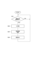
- step S01 the access management unit 141 waits for one user interface 500 to be connected to the simulation device 100.
- step S02 the access management unit 141 identifies the virtual controller 120 corresponding to the one user interface 500 based on the identification information specified by the one user interface 500.
- step S03 the access management unit 141 establishes communication between the one user interface 500 and the corresponding virtual controller 120. After that, the simulation device 100 returns the process to step S01. The simulation device 100 repeats the above process.
- the simulation device 100 may have a copy generation unit 181.
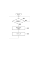
- FIG. 13 is a flowchart showing a pairing procedure when the simulation device 100 has the copy generation unit 181.
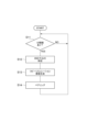
- the simulation device 100 executes steps S11, S12, S13, and S14.
- step S11 the access management unit 141 waits for one user interface 500 to be connected to the simulation device 100.
- step S12 the access management unit 141 identifies the virtual controller 120 corresponding to one user interface 500 based on the identification information specified by the one user interface 500.
- the copy generation unit 181 generates a copy simulation environment 110 corresponding to one user interface 500 as the simulation environment 101.
- the copy generation unit 181 generates the copy simulation environment 110 so as to be specialized for engineering by the corresponding user interface 500.
- the copy generation unit 181 does not assign communication identification information to virtual controllers 120 other than the virtual controller 120 corresponding to the user interface 500 in the copy simulation environment 110, thereby preventing other user interfaces 500 from accessing virtual controllers 120 other than the corresponding virtual controller 120.
- step S14 the access management unit 141 establishes communication between the user interface 500 in step S1 and the corresponding virtual controller 120 in the copy simulation environment 110. After that, the simulation device 100 returns the process to step S11. The simulation device 100 repeats the above process.
- step S24 the history display unit 162 displays the engineering history for the other virtual controllers 120 on the user interface 500 based on the history stored in the history holding unit 161. After that, the simulation device 100 returns the process to step S21. The simulation device 100 repeats the above process.
- step S34 the outdate detection unit 186 detects the outdate in the other copy simulation environment 110 of the copy setting 184 corresponding to the updated master setting 183, based on the generation timing of the other copy simulation environment 110 and the update history stored in the history storage unit 161.
- step S35 the copy generation unit 181 updates the copy setting 184 for which the outdate detection unit 186 has detected, based on the updated master setting 183.
- step S36 if the copy setting 184 is updated by the copy generation unit 181, the history display unit 162 displays the updated part on the user interface 500 corresponding to the other copy simulation environment 110. After that, the simulation device 100 returns the process to step S31. The simulation device 100 repeats the above process.
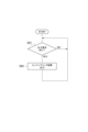
- step S41 the messenger 171 waits for a message to be input to the message window 523 in any of the two or more user interfaces 500 connected to the simulation device 100.
- step S42 the newly input message is added to the messages accumulated in chronological order, and the display in each of the message windows 523 of the two or more user interfaces 500 is updated so that the added message is included in the display.
- the simulation device 100 returns the process to step S41.
- the simulation device 100 repeats the above process.
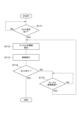
- step S51 the virtual host controller 121 acquires the state of the virtual space from the virtual space holding unit 144.
- step S52 it is confirmed whether or not there is a task that can be executed by any of the multiple virtual local controllers 122 based on the host control program and the state of the virtual space.
- step S52 If it is determined in step S52 that there is a task that can be executed by any of the multiple virtual local controllers 122, the simulation device 100 executes steps S53 and S54.
- step S53 the virtual host controller 121 commands the virtual local controller 122 that can execute the task to execute the task.
- step S54 the virtual host controller 121 checks whether or not execution of all tasks defined by the host control program has been completed.
- step S54 If it is determined in step S54 that there is an incomplete task, the simulation device 100 executes step S55. If it is determined in step S52 that there is no task that can be executed by any of the multiple virtual local controllers 122, the simulation device 100 executes step S55 without executing steps S53 and S54. In step S55, the virtual host controller 121 waits for a predetermined host period to elapse, counting from the start of step S51. The simulation device 100 then returns the process to step S51.
- step S54 If it is determined in step S54 that execution of all tasks has been completed, the simulation device 100 completes the host simulation procedure.
- step S65 the virtual local controller 122 waits for the local period to elapse, counting from the start of step S62. Thereafter, the simulation device 100 returns the process to step S62.
- step S64 the simulation device 100 returns the process to step S61 and waits for a command to execute the next task from the virtual host controller 121.
- the simulation device 100 repeats the above process.
- the simulation device 100 causes the multiple virtual local controllers 122 and the virtual space generation unit 143 to repeatedly execute the above process, whereby the multiple machines 5 cooperate in the virtual space, and the virtual space in which the multiple machines 5 cooperate is held in the virtual space holding unit 144.
- step S71 the viewpoint setting acquisition unit 151 checks whether or not there is a request for registering a viewpoint from the user interface 500. If it is determined in step S71 that there is no request for registering a viewpoint, the simulation device 100 executes step S72.
- step S72 the virtual space display unit 145 checks whether there is a request to display the virtual space from the user interface 500. If it is determined in step S72 that there is no request to display the virtual space, the simulation device 100 returns the process to step S71.
- step S73 the viewpoint setting acquisition unit 151 associates the viewpoint acquired from the user interface 500 with the identification information of the user interface 500 and stores the association in the viewpoint setting storage unit 152.
- step S74 the virtual space display unit 145 reads out the viewpoint associated with the user interface 500 that requested the display of the virtual space from the viewpoint setting storage unit 152.
- step S75 the virtual space stored in the virtual space storage unit 144 is converted into a two-dimensional image from the acquired viewpoint to generate a simulation video.
- step S76 the generated simulation video is displayed in the simulation window 522 of the user interface 500 that requested the display of the virtual space.
- the simulation device 100 After executing steps S73 and S76, the simulation device 100 returns the process to step S71.
- the simulation device 100 repeats the above process.
- step S81 the output unit 187 waits for a request to output the engineering results for the multiple virtual controllers 120 from any one of the multiple user interfaces 500 or the like.
- step S82 the output unit 187 outputs the engineering results for the multiple virtual controllers 120 to each of the multiple controllers 300. Each of the multiple controllers 300 holds the output engineering result. Thereafter, the simulation device 100 returns the process to step S81. The simulation device 100 repeats the above process.
- a host control procedure executed by the host controller 301 and a local control procedure executed by the local controller 302 based on the exported engineering results are illustrated.
- the host controller 301 executes steps S101 and S102.
- step S101 the host controller 301 updates environmental information of the real space.
- step S102 it is confirmed whether there is a task that can be executed by any of the multiple local controllers 302 based on the host control program and the environmental information.
- step S102 If it is determined in step S102 that there is a task that can be executed by any of the multiple local controllers 302, the host controller 301 executes steps S103 and S104.
- step S103 the host controller 301 commands the local controller 302 that can execute the task to execute the task.
- step S104 the host controller 301 checks whether or not execution of all tasks defined by the host control program has been completed.
- step S104 If it is determined in step S104 that there is an incomplete task, the host controller 301 executes step S105. If it is determined in step S102 that there is no task that can be executed by any of the multiple local controllers 302, the host controller 301 executes step S105 without executing steps S103 and S104. In step S105, the host controller 301 waits for a predetermined host period to elapse, counting from the start of step S101. The simulation device 100 then returns the process to step S101.
- step S104 If it is determined in step S104 that execution of all tasks has been completed, the host controller 301 completes the host control procedure.
- step S111 the local controller 302 waits for a command to execute a task from the host controller 301.
- step S112 the local controller 302 calculates a control target value (cycle target value) at the time when a predetermined local period has elapsed, based on a task program corresponding to the commanded task.
- step S113 the local controller 302 controls the actuators of the machine 5 so as to follow the cycle target value.
- step S114 the local controller 302 checks whether the task execution is complete.
- step S115 the local controller 302 waits for the local period to elapse, counting from the start of step S112. Thereafter, the local controller 302 returns the process to step S112.
- step S114 If it is determined in step S114 that the execution of the task is completed, the local controller 302 returns the process to step S111 and waits for a command to execute the next task from the host controller 301.
- the local controller 302 repeats the above process. By multiple local controllers 302 repeating the above process, multiple machines 5 cooperate in real space.
- a simulation system 7 that simulates a cell 2 having multiple types of machines 5 and multiple types of controllers 300 that cause the multiple types of machines 5 to cooperate with each other, the simulation system 7 including: a simulation environment 101 that causes multiple types of virtual controllers 120 corresponding to the multiple types of controllers 300 to simulate cooperation; and multiple types of user interfaces 500 that are accessible to each of the multiple types of virtual controllers 120 in the simulation environment 101, differ from each other depending on the type of the corresponding virtual controller 120, and are each specialized for engineering the corresponding virtual controller 120.
- engineering for each of the multiple types of controllers 300 can be performed individually by a user interface 500 specialized for engineering of the corresponding controller 300.
- the cell 2 can be efficiently constructed by collaboration between multiple users having different skills.
- engineering for each of the multiple types of virtual controllers 120 can be performed individually by a user interface 500 specialized for engineering of the corresponding virtual controller 120. Therefore, engineering by collaboration between multiple users having different skills can be performed in the simulation environment 101 separately from the construction of the hardware of the cell 2. Therefore, the efficiency of engineering for the cell 2 is improved.
- a history storage unit 161 that stores a history of engineering for the corresponding virtual controller 120 by each of the plurality of types of user interfaces 500.
- the simulation system 7 according to (3) further comprising a history display unit 162 that displays, on each of a plurality of types of user interfaces 500, the engineering history for the virtual controllers 120 other than the corresponding virtual controller 120 based on the history stored in the history storage unit 161. This allows each user to more easily grasp the engineering status of the entire cell 2.
- the simulation system 7 according to any one of (1) to (4), further comprising an access management unit 141 that allows the multiple types of user interfaces 500 to access the multiple types of virtual controllers 120 independently of each other.
- the access management unit 141 allows the user interface 500 to access the corresponding virtual controller 120, and since this access is independent of access between other user interfaces 500 and their corresponding virtual controllers 120, communication can be made with an appropriate communication partner, and the user can concentrate on the engineering that he or she needs to do without being aware of communication through other user interfaces 500.
- the simulation system 7 according to (5) further comprising a messenger 171 that causes a message input to one type of user interface 500 to be displayed on another type of user interface 500.
Landscapes
- Engineering & Computer Science (AREA)
- General Engineering & Computer Science (AREA)
- Manufacturing & Machinery (AREA)
- Quality & Reliability (AREA)
- Physics & Mathematics (AREA)
- General Physics & Mathematics (AREA)
- Automation & Control Theory (AREA)
- Robotics (AREA)
- Mechanical Engineering (AREA)
- Programmable Controllers (AREA)
Priority Applications (3)
| Application Number | Priority Date | Filing Date | Title |
|---|---|---|---|
| CN202380099340.1A CN121420258A (zh) | 2023-06-20 | 2023-06-20 | 模拟系统和模拟方法 |
| JP2025527274A JPWO2024261874A1 (https=) | 2023-06-20 | 2023-06-20 | |
| PCT/JP2023/022792 WO2024261874A1 (ja) | 2023-06-20 | 2023-06-20 | シミュレーションシステム及びシミュレーション方法 |
Applications Claiming Priority (1)
| Application Number | Priority Date | Filing Date | Title |
|---|---|---|---|
| PCT/JP2023/022792 WO2024261874A1 (ja) | 2023-06-20 | 2023-06-20 | シミュレーションシステム及びシミュレーション方法 |
Related Child Applications (1)
| Application Number | Title | Priority Date | Filing Date |
|---|---|---|---|
| US19/426,064 Continuation US20260115900A1 (en) | 2025-12-19 | Simulation system and simulation method |
Publications (1)
| Publication Number | Publication Date |
|---|---|
| WO2024261874A1 true WO2024261874A1 (ja) | 2024-12-26 |
Family
ID=93935176
Family Applications (1)
| Application Number | Title | Priority Date | Filing Date |
|---|---|---|---|
| PCT/JP2023/022792 Ceased WO2024261874A1 (ja) | 2023-06-20 | 2023-06-20 | シミュレーションシステム及びシミュレーション方法 |
Country Status (3)
| Country | Link |
|---|---|
| JP (1) | JPWO2024261874A1 (https=) |
| CN (1) | CN121420258A (https=) |
| WO (1) | WO2024261874A1 (https=) |
Citations (4)
| Publication number | Priority date | Publication date | Assignee | Title |
|---|---|---|---|---|
| JPH103303A (ja) * | 1996-06-14 | 1998-01-06 | Mitsubishi Electric Corp | インターフェース装置 |
| JP2004299049A (ja) * | 2003-03-28 | 2004-10-28 | Kuka Roboter Gmbh | 複数のマニピュレータを制御するための方法および装置 |
| JP2017102669A (ja) * | 2015-12-01 | 2017-06-08 | オムロン株式会社 | 管理システムおよび管理プログラム |
| JP2021193543A (ja) * | 2020-06-08 | 2021-12-23 | 株式会社安川電機 | 生産システム、セルコントローラ、ロボットコントローラ及び制御方法 |
-
2023
- 2023-06-20 JP JP2025527274A patent/JPWO2024261874A1/ja active Pending
- 2023-06-20 WO PCT/JP2023/022792 patent/WO2024261874A1/ja not_active Ceased
- 2023-06-20 CN CN202380099340.1A patent/CN121420258A/zh active Pending
Patent Citations (4)
| Publication number | Priority date | Publication date | Assignee | Title |
|---|---|---|---|---|
| JPH103303A (ja) * | 1996-06-14 | 1998-01-06 | Mitsubishi Electric Corp | インターフェース装置 |
| JP2004299049A (ja) * | 2003-03-28 | 2004-10-28 | Kuka Roboter Gmbh | 複数のマニピュレータを制御するための方法および装置 |
| JP2017102669A (ja) * | 2015-12-01 | 2017-06-08 | オムロン株式会社 | 管理システムおよび管理プログラム |
| JP2021193543A (ja) * | 2020-06-08 | 2021-12-23 | 株式会社安川電機 | 生産システム、セルコントローラ、ロボットコントローラ及び制御方法 |
Also Published As
| Publication number | Publication date |
|---|---|
| JPWO2024261874A1 (https=) | 2024-12-26 |
| CN121420258A (zh) | 2026-01-27 |
Similar Documents
| Publication | Publication Date | Title |
|---|---|---|
| CN113878572B (zh) | 控制系统、机器人系统以及控制方法 | |
| CN110573308B (zh) | 用于机器人设备的空间编程的基于计算机的方法及系统 | |
| JP6754883B1 (ja) | 制御システム、ローカルコントローラ及び制御方法 | |
| CN111381815B (zh) | 离线编程后置代码转换方法和基于该方法的双机器人协同智造系统、方法 | |
| CN102119072B (zh) | 有助于对离线编程机器人单元进行校准的方法和系统 | |
| JP7494155B2 (ja) | 生産システム、セルコントローラ、ロボットコントローラ及び制御方法 | |
| JP2020011328A (ja) | 自動経路生成装置 | |
| JP7624369B2 (ja) | 制御システム及び制御方法 | |
| JP2003114706A (ja) | 多関節汎用ロボットモデルの表示システム | |
| JP2024102220A (ja) | ロボットシステム、タスク生成装置及び制御方法 | |
| JP5272447B2 (ja) | 数値制御機械の動作シミュレータ | |
| WO2024261874A1 (ja) | シミュレーションシステム及びシミュレーション方法 | |
| US20260115900A1 (en) | Simulation system and simulation method | |
| CN118061191B (zh) | 基于mcd的icf靶微装配机器人虚拟调试方法 | |
| Hoyos et al. | Skill-based easy programming interface for industrial applications | |
| JP7374867B2 (ja) | 制御システム、ローカルコントローラ及び制御方法 | |
| Braumann et al. | Towards ar for large-scale robotics | |
| WO2024247173A1 (ja) | 制御システム及び制御方法 | |
| JP7780620B2 (ja) | 生産システム及び生産方法 | |
| JP2022135939A (ja) | 情報処理装置、ロボットシステム、物品の製造方法、情報処理方法、プログラム、及び記録媒体 | |
| JP2025086763A (ja) | ロボットシステム、及びロボットシステムの製造方法 | |
| Dagalakis | 1997 Deneb International Simulation Conference, Troy, Michigan, September 29 to October 3, 1997. |
Legal Events
| Date | Code | Title | Description |
|---|---|---|---|
| 121 | Ep: the epo has been informed by wipo that ep was designated in this application |
Ref document number: 23942311 Country of ref document: EP Kind code of ref document: A1 |
|
| ENP | Entry into the national phase |
Ref document number: 2025527274 Country of ref document: JP Kind code of ref document: A |
|
| WWE | Wipo information: entry into national phase |
Ref document number: 2025527274 Country of ref document: JP |
|
| NENP | Non-entry into the national phase |
Ref country code: DE |