WO2024259243A2 - Scattering matrix tomography with snapshot hyperspectral acquisition - Google Patents
Scattering matrix tomography with snapshot hyperspectral acquisition Download PDFInfo
- Publication number
- WO2024259243A2 WO2024259243A2 PCT/US2024/034022 US2024034022W WO2024259243A2 WO 2024259243 A2 WO2024259243 A2 WO 2024259243A2 US 2024034022 W US2024034022 W US 2024034022W WO 2024259243 A2 WO2024259243 A2 WO 2024259243A2
- Authority
- WO
- WIPO (PCT)
- Prior art keywords
- light signal
- sample
- image
- output
- input
- Prior art date
- Legal status (The legal status is an assumption and is not a legal conclusion. Google has not performed a legal analysis and makes no representation as to the accuracy of the status listed.)
- Ceased
Links
Classifications
-
- G—PHYSICS
- G01—MEASURING; TESTING
- G01N—INVESTIGATING OR ANALYSING MATERIALS BY DETERMINING THEIR CHEMICAL OR PHYSICAL PROPERTIES
- G01N21/00—Investigating or analysing materials by the use of optical means, i.e. using sub-millimetre waves, infrared, visible or ultraviolet light
- G01N21/17—Systems in which incident light is modified in accordance with the properties of the material investigated
- G01N21/47—Scattering, i.e. diffuse reflection
- G01N21/4795—Scattering, i.e. diffuse reflection spatially resolved investigating of object in scattering medium
-
- G—PHYSICS
- G01—MEASURING; TESTING
- G01B—MEASURING LENGTH, THICKNESS OR SIMILAR LINEAR DIMENSIONS; MEASURING ANGLES; MEASURING AREAS; MEASURING IRREGULARITIES OF SURFACES OR CONTOURS
- G01B9/00—Measuring instruments characterised by the use of optical techniques
- G01B9/02—Interferometers
- G01B9/0209—Low-coherence interferometers
- G01B9/02091—Tomographic interferometers, e.g. based on optical coherence
-
- G—PHYSICS
- G01—MEASURING; TESTING
- G01J—MEASUREMENT OF INTENSITY, VELOCITY, SPECTRAL CONTENT, POLARISATION, PHASE OR PULSE CHARACTERISTICS OF INFRARED, VISIBLE OR ULTRAVIOLET LIGHT; COLORIMETRY; RADIATION PYROMETRY
- G01J3/00—Spectrometry; Spectrophotometry; Monochromators; Measuring colours
- G01J3/28—Investigating the spectrum
- G01J3/2823—Imaging spectrometer
Definitions
- the present invention relates to imaging techniques with improved temporal performance.
- the Scattering Matrix Tomography (SMT) method for noninvasive 3D imaging within scattering media, such as biological tissue samples, has been previously disclosed.
- the scattering matrix contains vital information regarding how a sample scatters light at various angles and frequencies. This comprehensive data enables high-resolution 3D imaging deep within scattering materials.
- the current measurement scheme which necessitates scanning across all input and output channels and frequencies, is time-consuming and impractical for in-vivo imaging.
- a system for multi-spectral scattering-matrix tomography with snapshot hyperspectral acquisition includes an interference microscope subsystem that includes a broadband light source that provides an input broadband light signal.
- the interference microscope subsystem is configured to generate a combined broadband interference image signal that includes interference patterns between a sample beam and a reference beam.
- a hyperspectral imaging subsystem is configured to acquire the interference patterns for a plurality of output channels and a plurality of light frequencies in a single shot collected with a high-speed camera.
- a computing system is configured to transform the interference patterns into scattering matrix coefficients across the plurality of output channels and the plurality of light frequencies of output.
- a method for multi-spectral scattering-matrix tomography with snapshot hyperspectral acquisition includes a step of splitting an input broadband light signal into an incident sample light signal and a reference light signal.
- the input broadband light signal includes a plurality of light frequencies.
- the incident sample light signal is directed to focus onto a sample such that an output light signal scattered from the sample is generated.
- the focal point of the incident sample light signal is varied over a predetermined range of areas.
- the reference light signal is focused onto a reference mirror through an optical path that matches the optical path of the incident sample light signal to form a reflected reference light signal.
- the reflected reference light signal is passed through a grating which provides a constant wavevector shift for all frequencies.
- the reflected reference light signal passes through a pinhole used to select a first diffraction order signal from the grating while blocking other orders.
- the reflected reference light signal and the output sample light signal are combined to form a combined broadband interference image signal.
- a hyperspectral imaging scheme is applied such that various spectral components of the broadband interference image are separated and captured simultaneously.
- the hyperspectral imaging scheme includes steps of directing the combined image signal to a spatial light modulator, the spatial light modulator deflecting different image parts into separated angle ranges; collecting the different image parts in the separated angle ranges through a lens array to form a sliced image at a focal plane of the lens array; illuminating the sliced image on a blazed grating where the blazed grating diffracting light signals from the sliced image at different frequencies into different angles to form a dispersed light signal; collecting the dispersed light signal by a lens system; and imaging the dispersed light signal with a high-speed camera, the high-speed camera being placed on a conjugate plane of the spatial light modulator.
- the camera’s region of interest is determined by a product of output spatial pixels and the number of frequencies in the plurality of light frequencies.
- a system for multi-spectral scattering-matrix tomography includes a light source configured to generate an input light signal varied over a predetermined frequency range.
- the system also includes an optical subsystem that splits the input light signal into an incident light signal and a reference light signal and directs the incident light signal to a sample such that an output light signal includes light scattered from or transmitted through the sample, with the incident light signal varied over a predetermined range of incident angles or incident spatial focusing locations.
- a camera is configured to receive the output light signal and the reference light signal, wherein the reference light signal is directed at a constant angle with respect to the output light signal to allow for amplitude and phase calculation by off-axis holography.
- a computing device is configured to measure a total light signal as a coherent sum of the reference light signal and the output signal using the camera, collect the total light signal for each light frequency and each incident angle as collected total light signal data, calculate a reflection matrix or transmission matrix from the collected total light signal data, derive an image of the sample from the reflection matrix or transmission matrix by summing over angles and light frequencies, and apply one or more correction algorithms to the reflection matrix or transmission matrix to increase resolution and penetration depth.
- the one or more correction algorithms includes dispersion compensation, wavefront distortion correction, and spatially varying wavefront distortion correction.
- a computer-implemented inward-outward progression method involves input-output alternating (IOA) optimization and spatial basis truncation, singular value decomposition (SVD) for multiple scattering removal, Inward progression, and Outward progression.
- IOA input-output alternating
- Singular value decomposition (SVD) is used to remove multiple scattering, addressing the non-convex nature of IOA optimization by eliminating local optima.
- Inward progression focuses on optimizing the brightest zone in the image using IOA optimization, providing an initial guess for adjacent zones.
- a system for improving image quality in an imaging system by in- out progression includes a light source configured to generate an input light signal varied over a predetermined frequency range and an optical subsystem that splits the input light signal into an incident light signal and a reference light signal and directs the incident light signal to a sample such that an output light signal includes light scattered from or transmitted through the sample, with the incident light signal varied over a predetermined range of incident angles or incident spatial focusing locations.
- a camera is configured to receive the interference image that combines the output light signal and the reference light signal.
- a computing device is configured to: a) calculate a reflection matrix or transmission matrix from the collected interference image data and derive an image of the sample from the reflection matrix or transmission matrix by summing over angles and light frequencies; b) preprocess the output image to an initial in-out input image by performing a first singular value decomposition (SVD) to remove multiple scattering; c) identify a brightest location in the initial in-out input image, locate an initial optimization zone as an initial optimization zone around the brightest location, perform spatial basis truncation, and then use input-output alternating (IOA) optimization to optimize correction phases where the c ⁇ n and c° ut are Zernike weights, k 11 is the in-plane wavevector component of the incident light, and is k[j ,ut is the in-plane wavevector component of the scattered or output light, Z n is a wavefront of an n th Zernike polynomials, n is an integer label, initially, the Zernike weights are the
- FIGURE 1 Schematic of a system for multi-spectral scattering-matrix tomography with snapshot hyperspectral acquisition.
- FIGURE 2a Depiction of the full scattering matrix.
- FIGURE 2b Depiction of the truncated scattering matrix.
- FIGURE 3a Reconstruction formed from the full scattering matrix.
- FIGURE 3b Reconstruction formed from the truncated scattering matrix.
- FIGURE 4 Schematic of an input beam module of the system for multi-spectral scattering-matrix tomography of Figure 1.
- FIGURE 5 Schematic of a sample beam module of the system for multi-spectral scattering-matrix tomography of Figure 1.
- FIGURE 6 Schematic of a reference beam module and interferometry module of the system for multi-spectral scattering-matrix tomography of Figure 1.
- FIGURE 7a Schematic of a hyperspectral imaging subsystem of the system for multi- spectral scattering-matrix tomography of Figure 1.
- FIGURE 7b Schematic of an image slicing component of the hyperspectral imaging subsystem of Figure 7a.
- FIGURE 7c Schematic of a spectral shearing component of the hyperspectral imaging subsystem of Figure 7 a.
- FIGURE 8 Schematic of a system for multi-spectral scattering-matrix tomography includes a light source configured to generate an input light signal varied over a predetermined frequency range.
- FIGURES 9a, 9b, and 9c Virtual wavefront shaping and scattering matrix tomography (SMT).
- SMT Virtual wavefront shaping and scattering matrix tomography
- a Conventional imaging and wavefront shaping, with wavefront modulated by lenses and spatial light modulators (SLMs) and using feedback from guidestars
- b-c (z) Virtual wavefront shaping, with wavefront modulation and optimization performed digitally using noninvasive feedback from the reconstructed image
- the scattering matrix (k O ut, k , co) relates any incident field Ejn(kj n , a>) to the resulting scattered field E out (k out , o) .
- SMT corrects all of them digitally through a frequency-dependent phase 7(oi) that acts as a virtual pulse shaper, appropriate momenta and phase coefficients for the medium that act as a virtual index-corrected objective lens, and angle-dependent phases in (kj") and ⁇ > O ut(kfj ,ut ) that act as two virtual SLMs.
- FIGURES 10a and 10b Measurement of the hyperspectral reflection matrix, a, Off- axis holography is used to measure the phase and amplitude of fields scattered by the sample.
- BS beam splitter
- BE beam expander
- TL tube lens
- b Construction of the data cube by mapping the output angles with the camera, scanning the input angle with the galvo, and scanning the frequency with the tunable laser.
- FIGURES I la, 11b, 11c, l id, l ie, I lf, 11g, l lh, Hi, l lj, and I lk.
- Noninvasive imaging through mouse brain tissue a, Schematic of the sample and a scanning electron microscope image of the buried USAF target, b-d, Reflectance confocal microscopy (RCM), optical coherence tomography (OCT), and optical coherence microscopy (OCM) images at the USAF target plane, synthesized from the measured hyperspectral reflection matrix, e, SMT image.
- RCM Reflectance confocal microscopy
- OCT optical coherence tomography
- OCM optical coherence microscopy
- the wavefront correction phase maps for the 8 > ⁇ 8 zones in SMT.
- the SMT PSF of the sample exhibits a peak width comparable to that of the mirror in air and a peak height 70 times that of the OCM PSF.
- FIGURES 12a, 12b, 12c, 12d, 12e, 12f, 12g, 12h, 12i, 12j, 12k, and 121 Volumetric imaging inside a dense colloid.
- the sample consists of 500-nm-diameter TiO2 nanoparticles dispersed in PDMS, with an estimated transport mean free path of 1 mm.
- a-d, SMT, OCM, OCT, and RCM images built from the measured hyperspectral reflection matrix, e-h,
- a longitudinal slice of the images at y 20.6 pm and close-up views of three particles at different depths in the SMT image, i, Cross sections of the three particles;
- Ar r - r pea k.
- j Transverse slices at the depths of the three particles.
- Scale bars in e and j 10 pm. All images share the same normalization. Volumetric images and 2D slices use the same colorbar.
- FIGURES 13a and 13b la) is the image before wavefront correction while b) is the image with wavefront correction but not using the inward outward progression.
- FIGURE 14 Inward progression applying IOA optimization to optimize the entire image.
- FIGURE 15 Inward progression step showing small region around the brightest spot.
- FIGURE 16 Outward progression step applying correction phases of the brightest zone.
- FIGURE 17 Outward progression step applying weights of the brightest zone.
- FIGURE 18 Outward progression steps to optimize the outer zones.
- FIGURE 19 Outward progression steps to optimize the outer zones.
- integer ranges explicitly include all intervening integers.
- the integer range 1-10 explicitly includes 1, 2, 3, 4, 5, 6, 7, 8, 9, and 10.
- the range 1 to 100 includes 1, 2, 3, 4. . . . 97, 98, 99, 100.
- intervening numbers that are increments of the difference between the upper limit and the lower limit divided by 10 can be taken as alternative upper or lower limits. For example, if the range is 1.1. to 2.1 the following numbers 1.2, 1.3, 1.4, 1.5, 1.6, 1.7, 1.8, 1.9, and 2.0 can be selected as lower or upper limits.
- the term “less than” includes a lower non-included limit that is 5 percent of the number indicated after “less than.”
- a lower nonincludes limit means that the numerical quantity being described is greater than the value indicated as a lower non-included limited.
- “less than 20” includes a lower non-included limit of 1 in a refinement. Therefore, this refinement of “less than 20” includes a range between 1 and 20.
- the term “less than” includes a lower non-included limit that is, in increasing order of preference, 20 percent, 10 percent, 5 percent, 1 percent, or 0 percent of the number indicated after “less than.”
- connection to means that the electrical components referred to as connected to are in electrical communication.
- connected to means that the electrical components referred to as connected to are directly wired to each other.
- connected to means that the electrical components communicate wirelessly or by a combination of wired and wirelessly connected components.
- connected to means that one or more additional electrical components are interposed between the electrical components referred to as connected to with an electrical signal from an originating component being processed (e.g., filtered, amplified, modulated, rectified, attenuated, summed, subtracted, etc.) before being received to the component connected thereto.
- the term “electrical communication” means that an electrical signal is either directly or indirectly sent from an originating electronic device to a receiving electrical device. Indirect electrical communication can involve processing of the electrical signal, including but not limited to, filtering of the signal, amplification of the signal, rectification of the signal, modulation of the signal, attenuation of the signal, adding of the signal with another signal, subtracting the signal from another signal, subtracting another signal from the signal, and the like. Electrical communication can be accomplished with wired components, wirelessly connected components, or a combination thereof. [0046] The term “one or more” means “at least one” and the term “at least one” means “one or more.” The terms “one or more” and “at least one” include “plurality” as a subset.
- computing device refers generally to any device that can perform at least one function, including communicating with another computing device.
- a computing device includes a central processing unit that can execute program steps and memory for storing data and a program code.
- Examples of computing devices include, but are not limited to, desktop computers, notebook computers, laptop computers, mainframes, mobile phones, headsets such as augmented reality headsets, virtual reality headsets, mixed reality headsets, augmented reality devices, virtual reality devices, mixed reality devices, and the like.
- a computing device When a computing device is described as performing an action or method step, it is understood that the one or more computing devices are operable to and/or configured to perform the action or method step typically by executing one or more lines of source code.
- the actions or method steps can be encoded onto non-transitory memory (e.g., hard drives, optical drive, flash drives, and the like).
- the processes, methods, or algorithms disclosed herein can be deliverable to/implemented by a processing device, controller, or computer, which can include any existing programmable electronic control unit or dedicated electronic control unit.
- the processes, methods, or algorithms can be stored as data and instructions executable by a controller or computer in many forms including, but not limited to, information permanently stored on non-writable storage media such as ROM devices and information alterably stored on writeable storage media such as floppy disks, magnetic tapes, CDs, RAM devices, and other magnetic and optical media.
- the processes, methods, or algorithms can also be implemented in a software executable object.
- the processes, methods, or algorithms can be embodied in whole or in part using suitable hardware components, such as Application Specific Integrated Circuits (ASICs), Field-Programmable Gate Arrays (FPGAs), state machines, controllers, or other hardware components or devices, or a combination of hardware, software and firmware components.
- suitable hardware components such as Application Specific Integrated Circuits (ASICs), Field-Programmable Gate Arrays (FPGAs), state machines, controllers, or other hardware components or devices, or a combination of hardware, software and firmware components.
- PBS means polarizing beam splitter
- SMT Scattering Matrix Tomography
- SMT single -spectral scattering-matrix tomography
- Traditional SMT involves a method for 3D imaging within scattering media, such as biological tissues, by capturing detailed information on how the sample scatters light at various angles and frequencies. This process typically requires scanning across all input and output channels and frequencies, which can be time-consuming and impractical for certain applications, particularly in-vivo imaging.
- Traditional SMT systems use a comprehensive scattering matrix that includes numerous coefficients to represent the scattering characteristics of the sample. The scattering matrix contains vital information about how light interacts with the sample, detailing the scattering behavior at different angles and frequencies. This matrix is used to reconstruct high -resolution 3D images of the sample's internal structure.
- an incident broadband light signal is split into incident and reference signals.
- the incident light is directed onto the sample, generating scattered output light, while the reference light follows a separate optical path.
- the scattered output light from the sample and the reflected reference light are then combined to form a broadband interference image signal.
- the setup typically includes various optical components like beam splitters, gratings, and lenses to direct and manipulate the light signals.
- the comprehensive scattering matrix requires scanning and measuring across a wide range of spatial points and frequencies, which involves significant data collection and processing time. This approach, while providing detailed imaging, is often limited by the extensive time required for data acquisition and reconstruction.
- system 10 is designed for multi -spectral scattering-matrix tomography with snapshot hyperspectral acquisition.
- System 10 includes an interference microscope subsystem 12 and a hyperspectral imaging subsystem 14.
- the interference microscope subsystem 12 includes a broadband light source.
- the interference microscope subsystem is configured to generate a combined broadband interference image signal that includes interference patterns between a sample beam and a reference beam.
- the hyperspectral imaging subsystem 14 is configured to acquire the interference patterns for a plurality of output channels and a plurality of light frequencies in a single shot collected with a high-speed camera.
- the hyperspectral imaging subsystem 14 is configured to transform the interference patterns into two-dimensional (2D) spectral image blocks and collect the 2D spectral image blocks with a high-speed camera.
- the new system is designed to expedite the imaging process and facilitate in-vivo imaging.
- This approach employs a truncated scattering matrix scheme, which maintains sufficient information for high-quality imaging while significantly reducing the number of coefficients requiring measurement.
- the snap-shot hyperspectral imaging method is introduced. This method enables the simultaneous measurement of scattering matrix coefficients across hundreds of output channels and frequencies in a single shot. This method also takes advantage of the higher recording efficiency (# pixels per second) of the larger region of interest of the high-speed camera.
- a computing system 16 is configured to transform the interference patterns into scattering matrix coefficients across the plurality of output channels and the plurality of light frequencies of output.
- Sf u n(r out , r in ) is the full scattering matrix in the spatial basis where r in is the input focused location and r out is the output detection location.
- Sf U n( r out' r in)> r in and r out scan over the entire field of view.
- ⁇ Ar, r in ) is the truncated scattering matrix that contains only the near diagonal elements, with the input and output distance
- the truncated scattering matrix can provide sufficient information for high-quality imaging.
- S full (r out , r in ) including all the spatial points across the entire field of view of 50x50 pm 2 S truncated (
- ⁇ Ar 5 pm , r in ) can maintain a good imaging quality.
- the two benefits from using 5 truncated includes (1) reducing data size by at least 25 times (2) within the sample’s decorrelation time, the area size needs to be scanned and measured is 25 times smaller (10 x 10 compared to 50 x 50 pm 2 ).
- Figure 2a provides a reconstruction using the full scattering matrix while Figure 2b provides an analogous reconstructions using the truncated scattering matrix.
- multi-spectral scattering-matrix tomography system 10 includes an interference microscope subsystem 12 and a hyperspectral imaging subsystem 14.
- Interference microscope subsystem 12 includes input beam module 20, sample beam module 22 and reference beam module 24.
- Input beam module 20 is configured to provide and collimate the input broadband light signal, polarize it, and split it into an incident sample light signal and a reference light signal.
- Interference microscope subsystem 12 forms the reference beam and sample beam from broadband source 26.
- Sample beam module 22 is configured to focus the incident sample light signal onto the sample and scan over a sample plane. The sample beam is the light directed at the sample, where it interacts with the sample and scatters (including reflection and transmission), carrying information about the sample's internal structure.
- Interferometry module 28 combines the reflected reference light signal 30 and the output sample light signal 32 to form a combined broadband interference image signal.
- Hyperspectral imaging subsystem 14 includes a spatial light modulator 34 configured to deflect different image parts of a combined broadband interference image signal into separated angle ranges.
- a lens array 36 is configured to collect different spatial regions in the separated angle ranges and form a sliced image at a focal plane of plane of the lens array 36.
- a blazed grating 38 is configured to diffract light signals from the sliced image at different frequencies into different angles to form a dispersed light signal.
- a lens system 40 is configured to collect the dispersed light signal.
- a highspeed camera 42 is positioned on a conjugate plane of the spatial light modulator 34 and is configured to image the dispersed light signal.
- the hyperspectral imaging scheme includes the step of directing the combined image signal to the spatial light modulator 34.
- the spatial light modulator 34 deflects different image parts into separated angle ranges.
- the scheme also includes a step of collecting the different image parts in the separated angle ranges through the lens array to form the sliced image at the focal plane of the lens array.
- the scheme also includes a step of illuminating the sliced image on the blazed grating 38, where the blazed grating diffracts light signals from the sliced image at different frequencies into different angles to form the dispersed light signal.
- the scheme also includes steps of collecting the dispersed light signal by the lens system 40 and imaging the dispersed light signal with the high-speed camera 42.
- the high-speed camera 42 is placed on the conjugate plane of the spatial light modulator 34.
- an input broadband light signal 46 from broadband source 26 is split into a reference light signal 48 and an incident sample light signal 50 (step a).
- the input broadband light signal 46 includes a plurality of light frequencies.
- the incident sample light signal 50 is directed to focus onto sample 52 such that an output light signal scattered from the sample is generated.
- the focal point of the incident sample light signal is varied over a predetermined range of areas (step b).
- the reference light signal 48 is focused onto a reference mirror 54 through an optical path that matches the optical path of the incident sample light signal to form the reflected reference light signal 30 (step c).
- the reflected reference light signal 30 is passed through a grating 56 which provides a constant wavevector shift for all frequencies (step d).
- the reflected reference light signal is passed through a pinhole 58 used to select a first diffraction order signal from the grating 56 while blocking other orders (step e).
- the reflected reference light signal 30 and the output sample light signal 32 are combined to form a combined broadband interference image signal by interferometry module 28 (step f).
- a hyperspectral imaging scheme which includes steps of directing the combined image signal to a spatial light modulator 34 where the spatial light modulator deflects different image parts into separated angle ranges (step g 1 ); collecting the different image parts in the separated angle ranges through a lens array 36 to form a sliced image at a focal plane of the lens array (step g2); illuminating the sliced image on a blazed grating 38 where the blazed grating diffracting light signals from the sliced image at different frequencies into different angles to form a dispersed light signal (step g3); collecting the dispersed light signal by a lens system 40 (step g4); and imaging the dispersed light signal with a high-speed camera 42 where the high-speed camera being placed on a conjugate plane of the spatial light modulator 34 (step g5).
- a region of interest is determined by a product of output spatial pixels and the number of frequencies in the plurality of light frequencies.
- step a) is performed by an input beam module 20
- step b) is performed by a sample beam module 22
- steps c) through e) are performed by a reference beam module 24
- step f) is performed by an interferometry module 28
- step g) is performed by a hyperspectral imaging subsystem 14.
- the input beam module 20 includes a broadband source 26 that provides the input broadband light signal 46 and a collimating lens 64 that receives and collimates the input broadband light signal 46.
- Input beam module 20 also includes a first polarized beam splitter 66 that linearly polarizes the input broadband light signal from the collimating lens 64.
- Input beam module 20 also includes a second polarized beam splitter 67 that splits the input broadband light signal into the incident sample light signal and the reference light signal and a Fresnel rhomb positioned 70 between the first polarized beam splitter and the second beam splitter for adjusting a power ratio between the incident sample light signal and the reference light signal.
- the sample beam module 22 includes a pinhole 72 placed on the conjugate plane of the sample plane to truncate the output, selectively allowing outputs near the input location while blocking outputs distant from the incident focus location.
- a MEMS scanner 74 is placed on the conjugate plane of a back focal plane of the objective lens 68. Characteristically, the MEMS scanner 74 is configured to scan a focused input over a sample plane in sample 52.
- Sample beam module 22 also includes a quarter wave plate 76 through which the incident sample light signal and the output scattered light signal pass.
- Objective lens (OL) 68 focuses the incident sample light signal on the sample plan.
- reference beam module 24 includes reference mirror 54, grating 56, and a pinhole 58 as described above.
- Reference beam module 24 also includes a quarter wave plate 82 through which the reference light signal and the reflected reference light signal pass.
- the reference beam light is focused on a reference mirror 54.
- Reference beam module 24 also includes optical elements configured to match an optical path of the reference light signal to the optical path of the incident sample light signal.
- Lens 1, Lens 2, Lens 3, Lens 4, and OL are the same models as the ones used in the sample beam to match the optical path.
- the reflected light from the reference mirror 54 goes through a grating 56 which provides a constant wavevector shift for all the frequencies.
- a pinhole 58 is used to select the first diffraction order signal from the grating and block other orders.
- the use of the polarized beam splitter 55 and the quarter wave plate eliminates power loss during beam splitting, thereby providing a 4-fold increase in power efficiency.
- the interferometry imaging module 28 includes a non-polarized beam splitter 84 that combines the reflected reference light signal and the output sample light signal.
- hyperspectral imaging subsystem 14 includes the spatial light modulator 34, a first lens 86 that provides the different image parts in the separated angle ranges through the lens array 36 and lens 90, the blazed grating 38, the lens system 40, and the high-speed camera 42.
- the input image is projected on a spatial light modulator 34, which is placed at the front focal plane of lens 86.
- the SLM 34 deflects different image parts, parti, part2, part3, ... into separated angle ranges: angle range 1, angle range 2, angle range 3, ... All the angle ranges are collected by lens 86 and go through the lensletl, lenslet2, lenslet3, ... of a lens array 36.
- a sliced image is formed at its focal plane.
- the sliced image then goes through lens 90 and is illuminated on a blazed grating 38.
- the blazed grating 38 diffracts the light signals at different frequencies into different angles.
- the dispersed light signal is collected by lens system 40 and imaged by a high-speed camera.
- the camera sensor is placed on the conjugate plane of the SLM.
- the combination of a polarized beam splitter and a quarter wave plate gives a 4 times power efficiency than the case with a regular nonpolarized beam splitter (NBS).
- NBS nonpolarized beam splitter
- a method for multi-spectral scattering-matrix tomography with snapshot hyperspectral acquisition includes combining a reflected reference light signal and an output sample light signal to form a combined broadband interference image signal.
- the reflected reference light signal and the output sample light signal include a plurality of frequencies.
- the method also includes applying a hyperspectral imaging scheme. This scheme involves directing the combined broadband interference image signal to a spatial light modulator, which deflects different image parts into separated angle ranges. The different image parts are collected through a lens array to form a sliced image at a focal plane of the lens array.
- the sliced image is illuminated on a blazed grating, which diffracts light signals from the sliced image at different frequencies into different angles to form a dispersed light signal that includes interference patterns.
- the dispersed light signal is collected by a lens system and imaged with a high-speed camera placed on a conjugate plane of the spatial light modulator.
- the region of interest of the camera is determined by a product of output spatial pixels and the number of frequencies in the plurality of light frequencies.
- a computing device calculates scattering matrix coefficients across a plurality of output channels and the plurality of light frequencies by transforming the images collected by the camera into a plurality of interference patterns at different light frequencies and processing these interference patterns to calculate the phase and amplitude of scattering matrix coefficients across the plurality of output channels and the plurality of light frequencies.
- the method for multi-spectral scattering-matrix tomography includes creating the combined broadband interference image signal. This is done by splitting an input broadband light signal into an incident sample light signal and a reference light signal, where the input broadband light signal includes a plurality of light frequencies.
- the incident sample light signal is directed to focus onto a sample, generating an output light signal scattered from the sample, with the focal point of the incident sample light signal varied over a predetermined range of areas.
- the reference light signal is focused onto a reference mirror through an optical path matching the optical path of the incident sample light signal to form a reflected reference light signal.
- the reflected reference light signal passes through a grating providing a constant wavevector shift for all frequencies, and then through a pinhole used to select a first diffraction order signal from the grating while blocking other orders.
- the reflected reference light signal is then combined with the output sample light signal to form an interference pattern.
- the steps of the method for creating the combined broadband interference image signal are performed by specific subsystems.
- Step a) is performed by an input beam subsystem
- step b) is performed by a sample beam subsystem
- steps c) through e) are performed by a reference beam subsystem
- step f) is performed by an interferometry subsystem.
- the input beam subsystem includes a broadband source that provides the input broadband light signal.
- the input beam subsystem also includes a collimating lens that receives and collimates the input broadband light signal.
- a first polarized beam splitter linearly polarizes the input broadband light signal from the collimating lens.
- a second polarized beam splitter splits the input broadband light signal into the incident sample light signal and the reference light signal.
- a Fresnel rhomb is positioned between the first polarized beam splitter and the second polarized beam splitter to adjust the power ratio between the incident sample light signal and the reference light signal.
- the sample beam subsystem includes an objective lens that focuses the incident sample light signal on the sample.
- a pinhole is placed on the conjugate plane of a sample plane to truncate the output sample light signal, selectively allowing outputs near an input location while blocking outputs distant from an incident focus location.
- a MEMS scanner is placed on the conjugate plane of a back focal plane of the objective lens, and the MEMS scanner is configured to scan a focused input over the sample plane.
- the sample beam subsystem also includes a quarter wave plate through which the incident sample light signal and the output scattered light signal pass.
- the reference beam subsystem includes a quarter wave plate through which the reference light signal and the reflected reference light signal pass.
- the use of a polarized beam splitter and the quarter wave plate in the reference beam subsystem eliminates power loss during beam splitting, thereby providing a four-fold increase in power efficiency.
- the interferometry subsystem includes a non-polarized beam splitter that combines the reflected reference light signal and the output sample light signal.
- the hyperspectral imaging scheme is performed by a hyperspectral imaging subsystem.
- the hyperspectral imaging subsystem includes the spatial light modulator, a first lens that provides the different image parts in the separated angle ranges through the lens array, the blazed grating, the lens system, and the high-speed camera.
- a system and method for multi-spectral scattering-matrix tomography includes a light source 102 configured to generate an input light signal varied over a predetermined frequency range.
- the SMT system 100 also includes an optical subsystem 104 that splits the input light signal 106 into an incident light signal 108 and a reference light signal 110.
- Optical subsystem 104 directs the incident light signal to sample 112 such that an output light signal 114 includes light scattered from or transmitted through the sample, with the incident light signal varied over a predetermined range of incident angles.
- Sample 112 can be moved by movable sample holder 116.
- An imaging camera 118 is configured to receive the output light signal and the reference light signal, wherein the reference light signal is directed at a constant angle with respect to the output light signal to allow for amplitude and phase calculation by off-axis holography.
- System 100 includes a computing device 120 (i.e., a computing device) configured to measure a total light signal as a coherent sum of the reference light signal and the output signal using the camera.
- Computing device 120 is configured to collect a digitized total light signal for each light frequency and each incident angle as collected total light signal data.
- Computing device 120 is configured to calculate a reflection matrix or transmission matrix from the collected total light signal data.
- the computing device 120 is also configured to derive an image of the sample from the reflection matrix or transmission matrix by summing over angles and light frequencies.
- the computing device 120 is configured to apply one or more correction algorithms to the reflection matrix or transmission matrix to increase resolution and penetration depth, including dispersion compensation, wavefront distortion correction, and spatially varying wavefront distortion correction.
- the computing device 120 is configured to determine the reflection matrix or transmission matrix by Fourier transforming the collected total light signal data to form transformed collected total signal data and performing an inverse Fourier transform on a first-order region of the transformed collected total signal data to determine the amplitude and phase of the output signal.
- optical subsystem 104 includes a beam splitter 126 configured to split the input light signal into an incident light signal and a reference light signal.
- a method for multi-spectral scattering-matrix tomography includes a step of splitting an input light signal into an incident light signal and a reference light signal, wherein the input light signal is varied over a predetermined frequency range.
- the method also includes steps of directing the incident light signal to a sample in either a reflection configuration or a transmission configuration such that an output light signal includes light scattered from or transmitted through the sample, wherein the incident light signal is varied over a predetermined range of incident angles; directing the output light signal and the reference light signal to a camera, the output light signal directed at a constant angle with respect to the reference light signal to allow for amplitude and phase to be calculated by off-axis holography; measuring with the camera a total light signal that is a coherent sum of the reference light signal and the output signal; collecting the total light signal for each light frequency and each incident angle as collected total light signal data; calculating with a computing device a reflection matrix or transmission matrix from the collected total light signal data; and deriving an image of the sample from the reflection matrix or transmission matrix by summing over angles and summing over light frequencies.
- one or more computer-implemented correction methods are applied to increase resolution and penetration depth.
- the reflection matrix or transmission matrix is determined by Fourier transforming the collected total light signal data to form a transformed collected total signal data and performing an inverse Fourier transform on a first-order region of the transformed collected total signal data to determine amplitude and phase of the output signal.
- image intensity is determined from: where:
- I SMT is the image intensity as a function of position r in the sample; r is a position vector of a point in the sample;
- S(k out , kin, ⁇ ) is an element of the scattering matrix for an incidence channel with k in and a reflection channel with k out ;
- kin is a wavevector of the incident light signal;
- kout is the wavevector of the output (i.e., reflected) light signal;
- ⁇ ( ⁇ o) is a spectral phase;
- ⁇ in is an input correction phase;
- ⁇ out is an output correction phase;
- ⁇ is the light frequency.
- the one or more correction algorithms include a dispersion compensation algorithm comprising: introducing a frequency-dependent phase shift ⁇ ( ⁇ ) to the scattering matrix; precomputing an angular summation from: such that wherein 0 (co) is determined by maximizing an image quality metric is the scattering matrix.
- one variable at a time is optimized such that first a temporal gate is aligned with a spatial gates by scanning to obtain while keeping 0, then symmetric pulse compression is performed by scanning to obtain while keeping 0, and finally, asymmetric pulse compression is performed by scanning to obtain while keeping x .
- a local gradient based optimization is performed to optimize all three variables simultaneously, using ( , ) as an initial guess wherein a gradient of M with respect to is where I o is a reference intensity that is a normalization constant.
- the one or more correction algorithms include a wavefront distortion correction algorithm comprising an alternating optimization scheme including steps of: a) determining a target’s depth from a dispersion-compensated volumetric image by scanning a longitudinal direction z and selecting the depth where a 2D en face image yields a highest M. b) building a depth-resolved time-gated scattering matrix at a target’s depth zo from: where k° u1: and kj” are tranverse input and output wavenumbers, and are the longitudinal input and output wavenumbers, and c is the speed of light in the sample.
- e) determine the gradient of AY with respect to the Zemike weights e) optimize AY; f) building a matrix , co) with each column containing the image from a single output wherein these single-output images, denoted as are built by: g) determining the gradient of M with respect to the Zemike weights h) optimize AY; and i) alternate between optimizing ⁇ and until A converges.
- the one or more correction algorithms include a spatially varying wavefront distortion correction algorithm comprising: a) dividing the image into small zones, each zone being corrected with its own correction phase maps wherein optimization of these zones’ images is non-convex; b) optimizing sharpness of a whole image is the input-output alternating optimization scheme; c) dividing the whole image into 2 x 2 smaller zones with equal sizes wherein these zones are slightly overlapped; d) optimizing each zone separately with Zemike weights of the whole image being an initial guess; e) after optimization, further dividing each zone into 2 x 2 smaller zones, where the Zernike weights of each big zone serve as the initial guesses for the smaller zones it contains f) repeating steps c) to e) until no further improvement of image quality is observed, wherein the number of optimized Zernike polynomials is also increased after each division step with the weights of newly added Zernike polynomials are initialized as zeros.
- Figure 9a provides a schematic of conventional imaging and wavefront shaping, with wavefront modulated by lenses and spatial light modulators (SLMs) and using feedback from guidestars.
- Figure 9b-c illustrates the virtual spatiotemporal wavefront shaping approach, as described above. This approach not only combines all the strengths of the conventional methods but goes beyond them as schematically illustrated in Figure 9b-c, z.
- the hyperspectral scattering matrix of the sample was measured and used to virtually perform spatiotemporal focusing with high-speed Guidestar-free wavefront optimization for every isoplanatic patch, pulse compression, and refractive index mismatch correction.
- the focus digitally can be scanned to yield a phase-resolved 3D image of the sample with no depth-of-field trade-off.
- the scattering matrix [59, 60] encapsulates the sample’s complete linear response ( Figure 9b-c (zz)): any incident wave is a superposition of plane waves over momentum ki n and frequency co, and the resulting outgoing wave is given by the scattering matrix through .
- the angular summations are restricted to in a background medium with speed of light c/n bg .
- the sample’s response is digitally synthesized to virtually perform tailored measurements in space-time for customized spatiotemporal inputs.
- Digitally scanning r forms a phase-resolved 3D image of the sample where the three gates align at every point ( Figure 9b-c, /). This enables high lateral resolution and high axial resolution across a wide field of view and large depth of field, with no restriction on any focal plane.
- the non-uniform fast Fourier transform [61] is used to efficiently evaluate these summations and the spatial scan. This is the minimal form of “scattering matrix tomography” (SMT).
- MT efficiently suppresses multiple scattering.
- Such single-scattering contributions add up in phase in Eq. (1) to form the image, similar to an inverse Fourier transform from i](q) to r](r); meanwhile, the multiple-scattering contributions add up with quasi-random phases.
- the triple summations over co, kout, and k in boost the single-to- multiple-scattering ratio enable imaging even when multiple scattering is orders of magnitude stronger than single scattering in the raw data 5(k O ut, ki n , co).
- SMT also allows customized spatial and spectral corrections.
- the frequency dependence of the refractive index (i.e., dispersion) in the optical elements of the system and the sample creates a frequency-dependent phase that misaligns and broadens the temporal gate.
- SMT can overcome dispersion using a spectral phase 0(a), acting as a virtual pulse shaper ( Figure 9b-c, iv).
- the refractive index mismatch between the sample medium (e.g., biological tissue), the far field (e.g., air), and the coverslip (if there is one) refracts the rays and degrades the gates.
- the sample medium e.g., biological tissue
- the far field e.g., air
- the coverslip if there is one
- SMT can achieve an ideal focus even in the presence of refraction, effectively creating a virtual dry objective lens that perfectly focuses inside any refractive index at any depth ( Figure 9b-c, v) without expensive hardware or liquid immersion.
- the general form of SMT reads
- the measurement can use angular [64] or frequency [65, 66] scans at high speed, limited only by the camera frame rate (which can go beyond MHz for commercial cameras, orders of magnitude faster than the fastest SLMs).
- the subsequent wavefront optimization requires no additional measurement and outpaces SLM-based optimization even more.
- the absence of spatial or temporal focus during measurement prevents photodamage to the sample and also avoids localized saturation of the camera to allow for a higher signal-to-noise ratio.
- the synthesized pulse is concentrated at the target arrival time instead of spreading out across different times, providing another signal -to-noise- ratio advantage similar to that of frequency-domain OCT over time-domain OCT.
- the triple summation of SMT additionally suppresses uncorrelated noises in the scattering matrix data.
- the detection sensitivity currently limited by the residual reflection from the objective lens, is 90 dB.
- the 8th group (whose sixth element has a bar width of 1.1 pm) of a 1951 USAF resolution target underneath 0.98 mm of mouse brain tissue (Figure I la) is imaged.
- the imaging plane is chosen to maximize the total signal.
- corrections for the dispersion and input aberration of the optical system are included, as well as the dispersion of the sample.
- none of the three methods can reveal any group-8 element due to the overwhelming scattering from the mouse brain tissue.
- the SMT image also corrects the air-glass-sample index mismatches and incorporates optimized wavefronts that correct the multiple scattering from the sample and the output aberration of the optical system.
- the image quality metric over the full 50x50 pm 2 image with the same pin out; the summation over the many image pixels suppresses local oscillations of the objective function and makes the optimization problem more convex.
- the field of view 50 x 50 pm2
- the spatial dependence of the optimal wavefront is significant. Therefore, the image is progressively bisected and c
- the gradient-based optimization algorithm is used to perform local optimizations, using up to 275 Zernike polynomials in each of the 64 zos.
- the resulting (j) m and ⁇ ou t are shown in Figure I lf; note out(k
- ) # i n (— k
- SMT can image the USAF target with near perfection down to the smallest element of group 8 ( Figure He).
- the speckled OCM PSF averages to be 70 dB below the peak PSF of a mirror without the brain tissue ( Figure I lk), so the signal (which is buried beneath the speckled background and not visible here) has been reduced by at least ten-million-fold due to multiple scattering.
- the peak of the SMT PSF is 70 times higher than the averaged OCM PSF, indicating that the input and output wavefront corrections and the index-mismatch correction increase the signal by at least 70-fold.
- the SMT peak’s full width at half maximum (FWHM) is 1.08 pm, close to the 0.93 pm FWHM of the mirror PSF, demonstrating diffraction limited resolution despite the overwhelming multiple scattering.
- the depth-over-resolution ratio is 910 here.
- the lateral FWHM resolution is found to be submicron and the axial FWHM resolution close to the theoretical limit of 1.28 pm for the 206 nm bandwidth here, across the whole volume.
- SMT can work with reflection, transmission, remission, or a combination of them (such as a 4Pi microscope), in any basis.
- One may use the phase information of ipsm for digital staining and to resolve small nm-scale displacements for neuro imaging.
- One may incorporate polarization gating to select birefringent objects such as directionally oriented tissues.
- the hyperspectral scattering matrix can additionally resolve spectral information of the sample, such as the oxygenation of the hemoglobin.
- Additional details are found in Zhang Y, Dinh M, Wang Z, Zhang T, Chen T, Hsu CW. Deep imaging inside scattering media through virtual spatiotemporal wavefront shaping. arXiv preprint arXiv:2306.08793. 2023 Jun 15; the entire disclosure of which is hereby incorporated by reference
- system 100 includes a light source 103 configured to generate an input light signal varied over a predetermined frequency range.
- the system also includes an optical subsystem 14 that splits the input light signal into an incident light signal and a reference light signal and directs the incident light signal to a sample such that an output light signal includes light scattered from or transmitted through the sample, with the incident light signal varied over a predetermined range of incident angles.
- a camera is configured to receive the output light signal and the reference light signal and form an output image of a field of view.
- the system includes a computing device 120 configured to preprocess the output image to an initial in-out input image by performing a first singular value decomposition (SVD) to remove multiple scattering.
- the Zernike weights initially are for the entire field of view.
- the computing device iteratively shrinks the optimization zone and performs spatial basis truncation and IOA optimization for each progressively smaller zone using more Zemike polynomials than the initial optimization zone, where the c ⁇ ” and c° ut of a previous zone are initial parameters for the current zone. This shrinking of zones is repeated until a zone’s image attains a predefined sharpness.
- the computing device then iteratively expands the optimization zone outward by applying optimized correction phases (Zemike weights), ensuring that each newly included zone is optimized by performing additional IOA optimization steps, thereby progressively enhancing the image quality across the entire image. Finally, the system stitches the zones together to form a complete image of the field of view.
- Inward progression involves identifying the brightest zone in the image. This includes performing spatial basis truncation to limit the optimization to the relevant zones of the image. The process iteratively shrinks the zone and performs input-output alternating (IO A) optimization with increased correction detail using more Zemike polynomials.
- the spatial basis truncation involves converting the time-gated reflection matrix to spatial basis using a Fourier transform. The matrix elements outside the zone of interest are set to zero, and the truncated matrix is then converted back to angular basis for focused optimization.
- Out outward progression involves using the correction phases from the brightest zone to optimize surrounding zones.
- Singular Value Decomposition can be performed on the timegated reflection matrix to remove multiple scattering background.
- the optimized correction phases are iteratively applied to further zones to enhance.
- the images input to inward-outward progression are preprocessed with IOA optimization and spatial basis truncation and SVD for multiple scattering.
- the purpose of IOA optimization and spatial basis truncation is to iteratively optimize the correction phases for input and output wavefronts in an imaging system to improve the image quality by removing distortions caused by multiple scattering and other aberrations.
- the process aims to find the best possible correction phases that maximize the figure of merit M, which is a measure of image quality.
- M which is a measure of image quality.
- This step is crucial for achieving high-resolution, high-quality images in environments where wavefront distortions are significant, such as in biological tissues or other highly scattering media.
- the spatial basis truncation ensures that the optimization is focused on the relevant zones of the image, further enhancing the accuracy and efficiency of the correction.
- This step starts from the time-gated reflection matrix ) . Each row is one output with wavenumber 1 , each column is one input with wavenumber .
- the optimization finds the correction phases and for each input and each output.
- the corrected image is built from the by
- the correction phases are parameterized using Zernike polynomials and and are the weights ofthe n th Zernike polynomials, Z coordinate is the wavefront of the n th Zernike polynomials.
- the number of Zernike polynomials is a free parameter that should be sufficient to capture fast-varying wavefront distortion.
- the computing device 120 is further configured to optimize a figure of merit M for input optimization and output optimization.
- the figure of merit M is a function of and examples include a normalization constant).
- the gradient of M with respect to is:
- M is optimized using a gradient-based optimization algorithm. Then, perform output optimization to find . Precompute the single-output complex images: such that and c is the result of the previous input optimization.
- the gradient of M with respect to is:
- computing device 120 is further configured to: precompute single-output complex images: such that and Cn is a result of the previous input optimization; return to find c, 1 " using the same process, with the initial estimate being the cj from the previous step; find c° ut following the same method, using the c° ut from the prior step as the initial value, where the result of each input optimization, serves as the initial estimate for a next input optimization, the process of alternating between input and output optimization is repeated until the figure of merit M converges.
- the purpose for multiple scattering removal is to enhance image quality by removing the effects of multiple scattering, which manifests as a speckled background in images taken through scattering media.
- Singular Value Decomposition Singular Value Decomposition (SVD) to the time-gated reflection matrix, the method isolates and removes small singular values that correspond to multiple scattering contributions. Retaining only the large singular values, which represent the stronger single scattering signals, allows for a clearer, more accurate image.
- the singular value decomposition includes setting a threshold value to differentiate between small singular values corresponding to multiple scattering and large singular values corresponding to single scattering and removing singular values below the threshold to eliminate multiple scattering contributions.
- computing device 120 is configured to convert the optimized matrix back to the angular basis, resulting in a reflection matrix that highlights single scattering signals and reduces noise from multiple scattering, thereby improving the overall image resolution and quality.
- the time-gated reflection matrix S(k[j >ut , kj", z 0 ) is converted to spatial basis S(r
- the reflection matrix after SVD is:
- the output image of a field of view is processed by input-output alternating (IOA) optimization followed by a first SVD.
- IOA input-output alternating
- the IOA optimization involves precomputing single-input and single-output complex images for each input and output wavefront, constructing a total image intensity from the precomputed images, and maximizing an image quality metric
- the purpose of the inward progression is to incrementally refine the image quality by focusing on and optimizing the brightest zone, gradually shrinking the zone while increasing the correction detail using more Zernike polynomials. This process ensures high-quality wavefront correction phases for the central region, which can then be used as accurate initial guesses for optimizing neighboring regions.
- the purpose of outward progression is to systematically optimize image quality across all zones by using the correction phases of the brightest zone as initial guesses for surrounding areas. This iterative process ensures that wavefront distortions are minimized throughout the entire image, leading to high-resolution, high-quality imaging.
- outward progression involves using the correction phases of the brightest zone to optimize the surrounding zones and subsequently applying these optimized phases to further zones.
- a second Singular Value Decomposition SVD
- the second SVD focuses solely on removing the multiple scattering background, requiring more singular values to be retained.
- the correction phases of the brightest zone are applied to the new reflection matrix after the second SVD, providing good initial guesses for the regions around the brightest zone, which only need minor improvements.
Landscapes
- Physics & Mathematics (AREA)
- General Physics & Mathematics (AREA)
- General Health & Medical Sciences (AREA)
- Spectroscopy & Molecular Physics (AREA)
- Health & Medical Sciences (AREA)
- Radiology & Medical Imaging (AREA)
- Nuclear Medicine, Radiotherapy & Molecular Imaging (AREA)
- Optics & Photonics (AREA)
- Life Sciences & Earth Sciences (AREA)
- Chemical & Material Sciences (AREA)
- Analytical Chemistry (AREA)
- Biochemistry (AREA)
- Immunology (AREA)
- Pathology (AREA)
- Investigating Or Analysing Materials By Optical Means (AREA)
Abstract
A system for multi-spectral scattering-matrix tomography with snapshot hyperspectral acquisition includes an interference microscope subsystem with a broadband light source generating a combined broadband interference image signal from interference patterns between a sample beam and a reference beam. A hyperspectral imaging subsystem acquires these interference patterns for multiple output channels and light frequencies in a single shot using a high-speed camera. A computing system then transforms the interference patterns into scattering matrix coefficients across the output channels and light frequencies. Systems implementing image correction methods are also provided.
Description
SCATTERING MATRIX TOMOGRAPHY WITH SNAPSHOT HYPERSPECTRAL
ACQUISITION
CROSS-REFERENCE TO RELATED APPLICATIONS
10001] This application claims the benefit of U.S. provisional application Serial No. 63/472,900 filed June 14, 2023, and U.S. provisional application Serial No. 63/549,045 filed February 2, 2024, the disclosure of which is hereby incorporated in its entirety by reference herein.
TECHNICAL FIELD
[0002] In at least one aspect, the present invention relates to imaging techniques with improved temporal performance.
BACKGROUND
[0003] The Scattering Matrix Tomography (SMT) method for noninvasive 3D imaging within scattering media, such as biological tissue samples, has been previously disclosed. The scattering matrix contains vital information regarding how a sample scatters light at various angles and frequencies. This comprehensive data enables high-resolution 3D imaging deep within scattering materials. However, the current measurement scheme, which necessitates scanning across all input and output channels and frequencies, is time-consuming and impractical for in-vivo imaging.
[0004] Accordingly, there is a need for improved imaging techniques with improved time performance.
SUMMARY
|0005] In at least one aspect, a system for multi-spectral scattering-matrix tomography with snapshot hyperspectral acquisition is provided. The system includes an interference microscope subsystem that includes a broadband light source that provides an input broadband light signal. The interference microscope subsystem is configured to generate a combined broadband interference
 image signal that includes interference patterns between a sample beam and a reference beam. A hyperspectral imaging subsystem is configured to acquire the interference patterns for a plurality of output channels and a plurality of light frequencies in a single shot collected with a high-speed camera. A computing system is configured to transform the interference patterns into scattering matrix coefficients across the plurality of output channels and the plurality of light frequencies of output.
[0006] In another aspect, a method for multi-spectral scattering-matrix tomography with snapshot hyperspectral acquisition is provided. The method includes a step of splitting an input broadband light signal into an incident sample light signal and a reference light signal. Characteristically, the input broadband light signal includes a plurality of light frequencies. The incident sample light signal is directed to focus onto a sample such that an output light signal scattered from the sample is generated. The focal point of the incident sample light signal is varied over a predetermined range of areas. The reference light signal is focused onto a reference mirror through an optical path that matches the optical path of the incident sample light signal to form a reflected reference light signal. The reflected reference light signal is passed through a grating which provides a constant wavevector shift for all frequencies. The reflected reference light signal passes through a pinhole used to select a first diffraction order signal from the grating while blocking other orders. The reflected reference light signal and the output sample light signal are combined to form a combined broadband interference image signal. A hyperspectral imaging scheme is applied such that various spectral components of the broadband interference image are separated and captured simultaneously. The hyperspectral imaging scheme includes steps of directing the combined image signal to a spatial light modulator, the spatial light modulator deflecting different image parts into separated angle ranges; collecting the different image parts in the separated angle ranges through a lens array to form a sliced image at a focal plane of the lens array; illuminating the sliced image on a blazed grating where the blazed grating diffracting light signals from the sliced image at different frequencies into different angles to form a dispersed light signal; collecting the dispersed light signal by a lens system; and imaging the dispersed light signal with a high-speed camera, the high-speed camera being placed on a conjugate plane of the spatial light modulator. The camera’s region of interest is determined by a product of output spatial pixels and the number of frequencies in the plurality of light frequencies.
 [0007] A system for multi-spectral scattering-matrix tomography is provided. The multi- spectral scattering-matrix tomography system includes a light source configured to generate an input light signal varied over a predetermined frequency range. The system also includes an optical subsystem that splits the input light signal into an incident light signal and a reference light signal and directs the incident light signal to a sample such that an output light signal includes light scattered from or transmitted through the sample, with the incident light signal varied over a predetermined range of incident angles or incident spatial focusing locations. A camera is configured to receive the output light signal and the reference light signal, wherein the reference light signal is directed at a constant angle with respect to the output light signal to allow for amplitude and phase calculation by off-axis holography. A computing device is configured to measure a total light signal as a coherent sum of the reference light signal and the output signal using the camera, collect the total light signal for each light frequency and each incident angle as collected total light signal data, calculate a reflection matrix or transmission matrix from the collected total light signal data, derive an image of the sample from the reflection matrix or transmission matrix by summing over angles and light frequencies, and apply one or more correction algorithms to the reflection matrix or transmission matrix to increase resolution and penetration depth. The one or more correction algorithms includes dispersion compensation, wavefront distortion correction, and spatially varying wavefront distortion correction.
[0008] In another aspect, a computer-implemented inward-outward progression method involves input-output alternating (IOA) optimization and spatial basis truncation, singular value decomposition (SVD) for multiple scattering removal, Inward progression, and Outward progression. Input-output alternating (IOA) optimization and spatial basis truncation involve iteratively optimizing inputs and outputs in divided image zones to find the correction phases. Singular value decomposition (SVD) is used to remove multiple scattering, addressing the non-convex nature of IOA optimization by eliminating local optima. Inward progression focuses on optimizing the brightest zone in the image using IOA optimization, providing an initial guess for adjacent zones. Outward progression builds on this by using the correction phases from the brightest zone to optimize surrounding zones, progressively extending the optimization to outer zones
 [0009] In another aspect, a system for improving image quality in an imaging system by in- out progression is provided. The system includes a light source configured to generate an input light signal varied over a predetermined frequency range and an optical subsystem that splits the input light signal into an incident light signal and a reference light signal and directs the incident light signal to a sample such that an output light signal includes light scattered from or transmitted through the sample, with the incident light signal varied over a predetermined range of incident angles or incident spatial focusing locations. A camera is configured to receive the interference image that combines the output light signal and the reference light signal. A computing device is configured to: a) calculate a reflection matrix or transmission matrix from the collected interference image data and derive an image of the sample from the reflection matrix or transmission matrix by summing over angles and light frequencies; b) preprocess the output image to an initial in-out input image by performing a first singular value decomposition (SVD) to remove multiple scattering; c) identify a brightest location in the initial in-out input image, locate an initial optimization zone as an initial optimization zone around the brightest location, perform spatial basis truncation, and then use input-output alternating (IOA) optimization to optimize correction phases

 where the c^n and c°ut are Zernike weights, k 11 is the in-plane wavevector component of the incident light, and is k[j,ut is the in-plane wavevector component of the scattered or output light, Zn is a wavefront of an nth Zernike polynomials, n is an integer label, initially, the Zernike weights are the for an entire field of view; d) iteratively shrink the optimization zone and perform spatial basis truncation and IOA optimization for each progressively smaller zone using more Zernike polynomials than the initial optimization zone where the c^n and c°ut of a previous zone are initial parameters
 for a current zone, wherein shrinking of zones is repeated until a zone’s image attains a predefined sharpness; d) iteratively expand the optimization zone outward by applying optimized correction phases (Zemike weights), ensuring that each newly included zone is optimized by performing additional IOA optimization steps, thereby progressively enhancing the image quality across the entire image; e) stitching zones together to form a complete image of the field of view.
[0010] The foregoing summary is illustrative only and is not intended to be in any way limiting. In addition to the illustrative aspects, embodiments, and features described above, further aspects, embodiments, and features will become apparent by reference to the drawings and the following detailed description.
BRIEF DESCRIPTION OF THE DRAWINGS
[0011] For a further understanding of the nature, objects, and advantages of the present disclosure, reference should be made to the following detailed description, read in conjunction with the following drawings, wherein like reference numerals denote like elements and wherein:
[0012] FIGURE 1. Schematic of a system for multi-spectral scattering-matrix tomography with snapshot hyperspectral acquisition.
[0013] FIGURE 2a. Depiction of the full scattering matrix.
[0014] FIGURE 2b. Depiction of the truncated scattering matrix.
[0015] FIGURE 3a. Reconstruction formed from the full scattering matrix.
[0016] FIGURE 3b. Reconstruction formed from the truncated scattering matrix.
[0017] FIGURE 4. Schematic of an input beam module of the system for multi-spectral scattering-matrix tomography of Figure 1.
 [0018] FIGURE 5. Schematic of a sample beam module of the system for multi-spectral scattering-matrix tomography of Figure 1.
|0019] FIGURE 6. Schematic of a reference beam module and interferometry module of the system for multi-spectral scattering-matrix tomography of Figure 1.
[0020] FIGURE 7a. Schematic of a hyperspectral imaging subsystem of the system for multi- spectral scattering-matrix tomography of Figure 1.
[0021] FIGURE 7b. Schematic of an image slicing component of the hyperspectral imaging subsystem of Figure 7a.
[0022] FIGURE 7c. Schematic of a spectral shearing component of the hyperspectral imaging subsystem of Figure 7 a.
[0023] FIGURE 8. Schematic of a system for multi-spectral scattering-matrix tomography includes a light source configured to generate an input light signal varied over a predetermined frequency range.
[0024] FIGURES 9a, 9b, and 9c. Virtual wavefront shaping and scattering matrix tomography (SMT). a, Conventional imaging and wavefront shaping, with wavefront modulated by lenses and spatial light modulators (SLMs) and using feedback from guidestars, b-c: (z) Virtual wavefront shaping, with wavefront modulation and optimization performed digitally using noninvasive feedback from the reconstructed image, (zz) The scattering matrix (kOut, k , co) relates any incident field Ejn(kjn, a>) to the resulting scattered field Eout(kout, o) . (zzz) Given the scattering matrix, input spatial gating, output spatial gating, and time gating are performed by summing over the incident momentum kin, outgoing momentum kout, and frequency co respectively, (iv-v) Dispersion, refractive index mismatch at interfaces, and wavefront distortions (from both the optical system and the sample, including both aberrations and multiple scattering) can all degrade the gates. SMT corrects all of them digitally through a frequency-dependent phase 7(oi) that acts as a virtual pulse shaper, appropriate
 momenta and phase coefficients for the medium that act as a virtual index-corrected objective lens, and angle-dependent phases in (kj") and < >Out(kfj,ut) that act as two virtual SLMs.
[0025] FIGURES 10a and 10b. Measurement of the hyperspectral reflection matrix, a, Off- axis holography is used to measure the phase and amplitude of fields scattered by the sample. BS: beam splitter; BE: beam expander; TL: tube lens, b, Construction of the data cube by mapping the output angles with the camera, scanning the input angle with the galvo, and scanning the frequency with the tunable laser.
[0026] FIGURES I la, 11b, 11c, l id, l ie, I lf, 11g, l lh, Hi, l lj, and I lk. Noninvasive imaging through mouse brain tissue, a, Schematic of the sample and a scanning electron microscope image of the buried USAF target, b-d, Reflectance confocal microscopy (RCM), optical coherence tomography (OCT), and optical coherence microscopy (OCM) images at the USAF target plane, synthesized from the measured hyperspectral reflection matrix, e, SMT image. The full view and the zoom-in use the same colorbar. All images share the same normalization, with scales indicated on the colorbars. Scale bar: 10 pm. f, The wavefront correction phase maps for the 8 >< 8 zones in SMT. g-k, Corresponding point spread function PSF(r) of the sample (g-j) and of a mirror in air (k), centered at rin = (23.4, 45.0, 977.5) pm. The OCM PSF has no discernible peak near r = r;n and averages to be 10 7 times the height of the mirror PSF. The SMT PSF of the sample exhibits a peak width comparable to that of the mirror in air and a peak height 70 times that of the OCM PSF.
[0027] FIGURES 12a, 12b, 12c, 12d, 12e, 12f, 12g, 12h, 12i, 12j, 12k, and 121. Volumetric imaging inside a dense colloid. The sample consists of 500-nm-diameter TiO2 nanoparticles dispersed in PDMS, with an estimated transport mean free path of 1 mm. a-d, SMT, OCM, OCT, and RCM images built from the measured hyperspectral reflection matrix, e-h, A longitudinal slice of the images at y = 20.6 pm and close-up views of three particles at different depths in the SMT image, i, Cross sections of the three particles; Ar = r - rpeak. j, Transverse slices at the depths of the three particles. k,l, SMT images of particles separated horizontally (k) and vertically (1), with center-to-center cross sections, rpn = (21.6, 7.2, 1202.6) pm, rpi2 = (22.4, 7.4, 1202.8) pm, rp2i = (39.2, 11.4, 1201.4) pm,
 and rp22 = (38.6, 11.6, 1202.4) pm. Scale bars in e and j: 10 pm. All images share the same normalization. Volumetric images and 2D slices use the same colorbar.
|0028] FIGURES 13a and 13b. la) is the image before wavefront correction while b) is the image with wavefront correction but not using the inward outward progression.
[0029] FIGURE 14. Inward progression applying IOA optimization to optimize the entire image.
[0030] FIGURE 15. Inward progression step showing small region around the brightest spot.
[0031] FIGURE 16. Outward progression step applying correction phases of the brightest zone.
[0032] FIGURE 17. Outward progression step applying weights of the brightest zone.
[0033] FIGURE 18. Outward progression steps to optimize the outer zones.
[0034] FIGURE 19. Outward progression steps to optimize the outer zones.
DETAILED DESCRIPTION
[0035] Reference will now be made in detail to presently preferred embodiments and methods of the present invention, which constitute the best modes of practicing the invention presently known to the inventors. The Figures are not necessarily to scale. However, it is to be understood that the disclosed embodiments are merely exemplary of the invention that may be embodied in various and alternative forms. Therefore, specific details disclosed herein are not to be interpreted as limiting, but merely as a representative basis for any aspect of the invention and/or as a representative basis for teaching one skilled in the art to variously employ the present invention.
[0036] It is also to be understood that this invention is not limited to the specific embodiments and methods described below, as specific components and/or conditions may, of course, vary.
 Furthermore, the terminology used herein is used only for the purpose of describing particular embodiments of the present invention and is not intended to be limiting in any way.
|0037] It must also be noted that, as used in the specification and the appended claims, the singular form “a,” “an,” and “the” comprise plural referents unless the context clearly indicates otherwise. For example, reference to a component in the singular is intended to comprise a plurality of components.
[0038] The term “comprising” is synonymous with “including,” “having,” “containing,” or “characterized by.” These terms are inclusive and open-ended and do not exclude additional, unrecited elements or method steps.
|0039] The phrase “consisting of’ excludes any element, step, or ingredient not specified in the claim. When this phrase appears in a clause of the body of a claim, rather than immediately following the preamble, it limits only the element set forth in that clause; other elements are not excluded from the claim as a whole.
[0040] The phrase “consisting essentially of’ limits the scope of a claim to the specified materials or steps, plus those that do not materially affect the basic and novel character! stic(s) of the claimed subject matter.
[0041] With respect to the terms “comprising,” “consisting of,” and “consisting essentially of,” where one of these three terms is used herein, the presently disclosed and claimed subject matter can include the use of either of the other two terms.
[0042] It should also be appreciated that integer ranges explicitly include all intervening integers. For example, the integer range 1-10 explicitly includes 1, 2, 3, 4, 5, 6, 7, 8, 9, and 10. Similarly, the range 1 to 100 includes 1, 2, 3, 4. . . . 97, 98, 99, 100. Similarly, when any range is called for, intervening numbers that are increments of the difference between the upper limit and the lower limit divided by 10 can be taken as alternative upper or lower limits. For example, if the range is 1.1.
 to 2.1 the following numbers 1.2, 1.3, 1.4, 1.5, 1.6, 1.7, 1.8, 1.9, and 2.0 can be selected as lower or upper limits.
|0043] When referring to a numerical quantity, in a refinement, the term “less than” includes a lower non-included limit that is 5 percent of the number indicated after “less than.” A lower nonincludes limit means that the numerical quantity being described is greater than the value indicated as a lower non-included limited. For example, “less than 20” includes a lower non-included limit of 1 in a refinement. Therefore, this refinement of “less than 20” includes a range between 1 and 20. In another refinement, the term “less than” includes a lower non-included limit that is, in increasing order of preference, 20 percent, 10 percent, 5 percent, 1 percent, or 0 percent of the number indicated after “less than.”
[0044] With respect to electrical devices, the term “connected to” means that the electrical components referred to as connected to are in electrical communication. In a refinement, “connected to” means that the electrical components referred to as connected to are directly wired to each other. In another refinement, “connected to” means that the electrical components communicate wirelessly or by a combination of wired and wirelessly connected components. In another refinement, “connected to” means that one or more additional electrical components are interposed between the electrical components referred to as connected to with an electrical signal from an originating component being processed (e.g., filtered, amplified, modulated, rectified, attenuated, summed, subtracted, etc.) before being received to the component connected thereto.
[0045] The term “electrical communication” means that an electrical signal is either directly or indirectly sent from an originating electronic device to a receiving electrical device. Indirect electrical communication can involve processing of the electrical signal, including but not limited to, filtering of the signal, amplification of the signal, rectification of the signal, modulation of the signal, attenuation of the signal, adding of the signal with another signal, subtracting the signal from another signal, subtracting another signal from the signal, and the like. Electrical communication can be accomplished with wired components, wirelessly connected components, or a combination thereof.
 [0046] The term “one or more” means “at least one” and the term “at least one” means “one or more.” The terms “one or more” and “at least one” include “plurality” as a subset.
|0047] The term “substantially,” “generally,” or “about” may be used herein to describe disclosed or claimed embodiments. The term “substantially” may modify a value or relative characteristic disclosed or claimed in the present disclosure. In such instances, “substantially” may signify that the value or relative characteristic it modifies is within ± 0%, 0.1%, 0.5%, 1%, 2%, 3%, 4%, 5% or 10%.
[0048] The term “computing device” refers generally to any device that can perform at least one function, including communicating with another computing device. In a refinement, a computing device includes a central processing unit that can execute program steps and memory for storing data and a program code. Examples of computing devices include, but are not limited to, desktop computers, notebook computers, laptop computers, mainframes, mobile phones, headsets such as augmented reality headsets, virtual reality headsets, mixed reality headsets, augmented reality devices, virtual reality devices, mixed reality devices, and the like.
10049] When a computing device is described as performing an action or method step, it is understood that the one or more computing devices are operable to and/or configured to perform the action or method step typically by executing one or more lines of source code. The actions or method steps can be encoded onto non-transitory memory (e.g., hard drives, optical drive, flash drives, and the like).
[0050] The processes, methods, or algorithms disclosed herein can be deliverable to/implemented by a processing device, controller, or computer, which can include any existing programmable electronic control unit or dedicated electronic control unit. Similarly, the processes, methods, or algorithms can be stored as data and instructions executable by a controller or computer in many forms including, but not limited to, information permanently stored on non-writable storage media such as ROM devices and information alterably stored on writeable storage media such as floppy disks, magnetic tapes, CDs, RAM devices, and other magnetic and optical media. The
 processes, methods, or algorithms can also be implemented in a software executable object. Alternatively, the processes, methods, or algorithms can be embodied in whole or in part using suitable hardware components, such as Application Specific Integrated Circuits (ASICs), Field-Programmable Gate Arrays (FPGAs), state machines, controllers, or other hardware components or devices, or a combination of hardware, software and firmware components.
[0051] Abbreviations:
[0052] “PBS” means polarizing beam splitter.
[0053] “SMT” means Scattering Matrix Tomography.
[0054] 1. Scattering Matrix Tomography With Snapshot Hyperspectral Acquisition
[0055] In general, improvements to traditional multi -spectral scattering-matrix tomography (SMT) are provided. Traditional SMT involves a method for 3D imaging within scattering media, such as biological tissues, by capturing detailed information on how the sample scatters light at various angles and frequencies. This process typically requires scanning across all input and output channels and frequencies, which can be time-consuming and impractical for certain applications, particularly in-vivo imaging. Traditional SMT systems use a comprehensive scattering matrix that includes numerous coefficients to represent the scattering characteristics of the sample. The scattering matrix contains vital information about how light interacts with the sample, detailing the scattering behavior at different angles and frequencies. This matrix is used to reconstruct high -resolution 3D images of the sample's internal structure. In these systems, an incident broadband light signal is split into incident and reference signals. The incident light is directed onto the sample, generating scattered output light, while the reference light follows a separate optical path. The scattered output light from the sample and the reflected reference light are then combined to form a broadband interference image signal. The setup typically includes various optical components like beam splitters, gratings, and lenses to direct and manipulate the light signals. The comprehensive scattering matrix requires scanning and measuring across a wide range of spatial points and frequencies, which involves significant data
 collection and processing time. This approach, while providing detailed imaging, is often limited by the extensive time required for data acquisition and reconstruction.
|0056] In at least one aspect, traditional multi-spectral scattering-matrix tomography is enhanced by combining scattering matrix tomography with snapshot hyperspectral acquisition. Referring to Figure 1, system 10 is designed for multi -spectral scattering-matrix tomography with snapshot hyperspectral acquisition. System 10 includes an interference microscope subsystem 12 and a hyperspectral imaging subsystem 14. The interference microscope subsystem 12 includes a broadband light source. The interference microscope subsystem is configured to generate a combined broadband interference image signal that includes interference patterns between a sample beam and a reference beam. The hyperspectral imaging subsystem 14 is configured to acquire the interference patterns for a plurality of output channels and a plurality of light frequencies in a single shot collected with a high-speed camera. In this regard, the hyperspectral imaging subsystem 14 is configured to transform the interference patterns into two-dimensional (2D) spectral image blocks and collect the 2D spectral image blocks with a high-speed camera. The new system is designed to expedite the imaging process and facilitate in-vivo imaging. This approach employs a truncated scattering matrix scheme, which maintains sufficient information for high-quality imaging while significantly reducing the number of coefficients requiring measurement. Moreover, the snap-shot hyperspectral imaging method is introduced. This method enables the simultaneous measurement of scattering matrix coefficients across hundreds of output channels and frequencies in a single shot. This method also takes advantage of the higher recording efficiency (# pixels per second) of the larger region of interest of the high-speed camera. The Scattering Matrix Tomography with Snapshot Hyperspectral Acquisition shortens the time required for data collection, making real-time, high-resolution deep in- vino imaging feasible. A computing system 16 is configured to transform the interference patterns into scattering matrix coefficients across the plurality of output channels and the plurality of light frequencies of output.
[0057] Referring to Figures 2a and 2b, the application of the truncated scattering matrix is described. Sfun(rout, rin) is the full scattering matrix in the spatial basis where rin is the input focused location and rout is the output detection location. In SfUn(rout'rin)> rinand rout scan over the entire
 field of view. truncated ( | rout — rin | < Ar, rin) is the truncated scattering matrix that contains only the near diagonal elements, with the input and output distance |rout — rin l smaller than a given (predetermined value of Ar. Advantageously, the truncated scattering matrix can provide sufficient information for high-quality imaging. When compared to Sfull(rout, rin) including all the spatial points across the entire field of view of 50x50 pm2, Struncated(|rout — rin | < Ar = 5 pm , rin) can maintain a good imaging quality. Moreover, the two benefits from using 5truncated includes (1) reducing data size by at least 25 times (2) within the sample’s decorrelation time, the area size needs to be scanned and measured is 25 times smaller (10 x 10 compared to 50 x 50 pm2 ). Figure 2a provides a reconstruction using the full scattering matrix while Figure 2b provides an analogous reconstructions using the truncated scattering matrix.
[0058] Referring to Figure 1, multi-spectral scattering-matrix tomography system 10 includes an interference microscope subsystem 12 and a hyperspectral imaging subsystem 14. Interference microscope subsystem 12 includes input beam module 20, sample beam module 22 and reference beam module 24. Input beam module 20 is configured to provide and collimate the input broadband light signal, polarize it, and split it into an incident sample light signal and a reference light signal. Interference microscope subsystem 12 forms the reference beam and sample beam from broadband source 26. Sample beam module 22 is configured to focus the incident sample light signal onto the sample and scan over a sample plane. The sample beam is the light directed at the sample, where it interacts with the sample and scatters (including reflection and transmission), carrying information about the sample's internal structure. Interferometry module 28 combines the reflected reference light signal 30 and the output sample light signal 32 to form a combined broadband interference image signal. Hyperspectral imaging subsystem 14 includes a spatial light modulator 34 configured to deflect different image parts of a combined broadband interference image signal into separated angle ranges. A lens array 36 is configured to collect different spatial regions in the separated angle ranges and form a sliced image at a focal plane of plane of the lens array 36. A blazed grating 38 is configured to diffract light signals from the sliced image at different frequencies into different angles to form a dispersed light signal. A lens system 40 is configured to collect the dispersed light signal. A highspeed camera 42 is positioned on a conjugate plane of the spatial light modulator 34 and is configured
 to image the dispersed light signal. The hyperspectral imaging scheme includes the step of directing the combined image signal to the spatial light modulator 34. The spatial light modulator 34 deflects different image parts into separated angle ranges. The scheme also includes a step of collecting the different image parts in the separated angle ranges through the lens array to form the sliced image at the focal plane of the lens array. The scheme also includes a step of illuminating the sliced image on the blazed grating 38, where the blazed grating diffracts light signals from the sliced image at different frequencies into different angles to form the dispersed light signal. The scheme also includes steps of collecting the dispersed light signal by the lens system 40 and imaging the dispersed light signal with the high-speed camera 42. The high-speed camera 42 is placed on the conjugate plane of the spatial light modulator 34.
[0059] Still referring to Figure 1, details of the method and system for multi-spectral scattering-matrix tomography with snapshot hyperspectral acquisition are discussed in further detail. With respect to system 10, an input broadband light signal 46 from broadband source 26 is split into a reference light signal 48 and an incident sample light signal 50 (step a). Characteristically, the input broadband light signal 46 includes a plurality of light frequencies. The incident sample light signal 50 is directed to focus onto sample 52 such that an output light signal scattered from the sample is generated. Advantageously, the focal point of the incident sample light signal is varied over a predetermined range of areas (step b). The reference light signal 48 is focused onto a reference mirror 54 through an optical path that matches the optical path of the incident sample light signal to form the reflected reference light signal 30 (step c). The reflected reference light signal 30 is passed through a grating 56 which provides a constant wavevector shift for all frequencies (step d). The reflected reference light signal is passed through a pinhole 58 used to select a first diffraction order signal from the grating 56 while blocking other orders (step e). The reflected reference light signal 30 and the output sample light signal 32 are combined to form a combined broadband interference image signal by interferometry module 28 (step f). A hyperspectral imaging scheme is applied which includes steps of directing the combined image signal to a spatial light modulator 34 where the spatial light modulator deflects different image parts into separated angle ranges (step g 1 ); collecting the different image parts in the separated angle ranges through a lens array 36 to form a sliced image at a focal plane of the lens
 array (step g2); illuminating the sliced image on a blazed grating 38 where the blazed grating diffracting light signals from the sliced image at different frequencies into different angles to form a dispersed light signal (step g3); collecting the dispersed light signal by a lens system 40 (step g4); and imaging the dispersed light signal with a high-speed camera 42 where the high-speed camera being placed on a conjugate plane of the spatial light modulator 34 (step g5). Advantageously, when using the hyperspectral imaging scheme, a region of interest is determined by a product of output spatial pixels and the number of frequencies in the plurality of light frequencies.
[0060] In another aspect, step a) is performed by an input beam module 20, step b) is performed by a sample beam module 22, steps c) through e) are performed by a reference beam module 24, step f) is performed by an interferometry module 28, and step g) is performed by a hyperspectral imaging subsystem 14.
[0061] Referring to Figure 4, the input beam module 20 includes a broadband source 26 that provides the input broadband light signal 46 and a collimating lens 64 that receives and collimates the input broadband light signal 46. Input beam module 20 also includes a first polarized beam splitter 66 that linearly polarizes the input broadband light signal from the collimating lens 64. Input beam module 20 also includes a second polarized beam splitter 67 that splits the input broadband light signal into the incident sample light signal and the reference light signal and a Fresnel rhomb positioned 70 between the first polarized beam splitter and the second beam splitter for adjusting a power ratio between the incident sample light signal and the reference light signal.
[0062] Referring to Figure 5, the sample beam module 22 includes a pinhole 72 placed on the conjugate plane of the sample plane to truncate the output, selectively allowing outputs near the input location while blocking outputs distant from the incident focus location. A MEMS scanner 74 is placed on the conjugate plane of a back focal plane of the objective lens 68. Characteristically, the MEMS scanner 74 is configured to scan a focused input over a sample plane in sample 52. Sample beam module 22 also includes a quarter wave plate 76 through which the incident sample light signal and the output scattered light signal pass. Objective lens (OL) 68 focuses the incident sample light signal on the sample plan.
 [0063] Referring to Figure 6, reference beam module 24 includes reference mirror 54, grating 56, and a pinhole 58 as described above. Reference beam module 24 also includes a quarter wave plate 82 through which the reference light signal and the reflected reference light signal pass. The reference beam light is focused on a reference mirror 54. Reference beam module 24 also includes optical elements configured to match an optical path of the reference light signal to the optical path of the incident sample light signal. In this regard, Lens 1, Lens 2, Lens 3, Lens 4, and OL are the same models as the ones used in the sample beam to match the optical path. The reflected light from the reference mirror 54 goes through a grating 56 which provides a constant wavevector shift for all the frequencies. After the grating 56 a pinhole 58 is used to select the first diffraction order signal from the grating and block other orders. Advantageously, the use of the polarized beam splitter 55 and the quarter wave plate eliminates power loss during beam splitting, thereby providing a 4-fold increase in power efficiency.
[0064] Referring to Figure 6, the interferometry imaging module 28 includes a non-polarized beam splitter 84 that combines the reflected reference light signal and the output sample light signal.
[0065] Referring to Figure 7a, hyperspectral imaging subsystem 14 includes the spatial light modulator 34, a first lens 86 that provides the different image parts in the separated angle ranges through the lens array 36 and lens 90, the blazed grating 38, the lens system 40, and the high-speed camera 42. Referring to Figure 7b, the input image is projected on a spatial light modulator 34, which is placed at the front focal plane of lens 86. The SLM 34 deflects different image parts, parti, part2, part3, ... into separated angle ranges: angle range 1, angle range 2, angle range 3, ... All the angle ranges are collected by lens 86 and go through the lensletl, lenslet2, lenslet3, ... of a lens array 36. After the lens array 36, a sliced image is formed at its focal plane. Referring to Figure 7c, the sliced image then goes through lens 90 and is illuminated on a blazed grating 38. The blazed grating 38 diffracts the light signals at different frequencies into different angles. The dispersed light signal is collected by lens system 40 and imaged by a high-speed camera. The camera sensor is placed on the conjugate plane of the SLM. The combination of a polarized beam splitter and a quarter wave plate gives a 4 times power efficiency than the case with a regular nonpolarized beam splitter (NBS). When
 using a regular NBS, the light power is reduced by half each time it goes through the NBS, resulting in a total loss of 1/4.
|0066] In another aspect, a method for multi-spectral scattering-matrix tomography with snapshot hyperspectral acquisition includes combining a reflected reference light signal and an output sample light signal to form a combined broadband interference image signal. The reflected reference light signal and the output sample light signal include a plurality of frequencies. The method also includes applying a hyperspectral imaging scheme. This scheme involves directing the combined broadband interference image signal to a spatial light modulator, which deflects different image parts into separated angle ranges. The different image parts are collected through a lens array to form a sliced image at a focal plane of the lens array. The sliced image is illuminated on a blazed grating, which diffracts light signals from the sliced image at different frequencies into different angles to form a dispersed light signal that includes interference patterns. The dispersed light signal is collected by a lens system and imaged with a high-speed camera placed on a conjugate plane of the spatial light modulator. The region of interest of the camera is determined by a product of output spatial pixels and the number of frequencies in the plurality of light frequencies. A computing device calculates scattering matrix coefficients across a plurality of output channels and the plurality of light frequencies by transforming the images collected by the camera into a plurality of interference patterns at different light frequencies and processing these interference patterns to calculate the phase and amplitude of scattering matrix coefficients across the plurality of output channels and the plurality of light frequencies.
[0067] In another aspect, the method for multi-spectral scattering-matrix tomography includes creating the combined broadband interference image signal. This is done by splitting an input broadband light signal into an incident sample light signal and a reference light signal, where the input broadband light signal includes a plurality of light frequencies. The incident sample light signal is directed to focus onto a sample, generating an output light signal scattered from the sample, with the focal point of the incident sample light signal varied over a predetermined range of areas. The reference light signal is focused onto a reference mirror through an optical path matching the optical path of the incident sample light signal to form a reflected reference light signal. The reflected
 reference light signal passes through a grating providing a constant wavevector shift for all frequencies, and then through a pinhole used to select a first diffraction order signal from the grating while blocking other orders. The reflected reference light signal is then combined with the output sample light signal to form an interference pattern.
[0068J In another aspect, the steps of the method for creating the combined broadband interference image signal are performed by specific subsystems. Step a) is performed by an input beam subsystem, step b) is performed by a sample beam subsystem, steps c) through e) are performed by a reference beam subsystem, and step f) is performed by an interferometry subsystem.
|0069] In another aspect, the input beam subsystem includes a broadband source that provides the input broadband light signal. The input beam subsystem also includes a collimating lens that receives and collimates the input broadband light signal. A first polarized beam splitter linearly polarizes the input broadband light signal from the collimating lens. A second polarized beam splitter splits the input broadband light signal into the incident sample light signal and the reference light signal. A Fresnel rhomb is positioned between the first polarized beam splitter and the second polarized beam splitter to adjust the power ratio between the incident sample light signal and the reference light signal.
[0070] In another aspect, the sample beam subsystem includes an objective lens that focuses the incident sample light signal on the sample. A pinhole is placed on the conjugate plane of a sample plane to truncate the output sample light signal, selectively allowing outputs near an input location while blocking outputs distant from an incident focus location. A MEMS scanner is placed on the conjugate plane of a back focal plane of the objective lens, and the MEMS scanner is configured to scan a focused input over the sample plane. The sample beam subsystem also includes a quarter wave plate through which the incident sample light signal and the output scattered light signal pass.
[0071] In another aspect, the reference beam subsystem includes a quarter wave plate through which the reference light signal and the reflected reference light signal pass.
 [0072] In another aspect, the use of a polarized beam splitter and the quarter wave plate in the reference beam subsystem eliminates power loss during beam splitting, thereby providing a four-fold increase in power efficiency.
[0073] In another aspect, the interferometry subsystem includes a non-polarized beam splitter that combines the reflected reference light signal and the output sample light signal.
[0074] In another aspect, the hyperspectral imaging scheme is performed by a hyperspectral imaging subsystem.
[0075] In another aspect, the hyperspectral imaging subsystem includes the spatial light modulator, a first lens that provides the different image parts in the separated angle ranges through the lens array, the blazed grating, the lens system, and the high-speed camera.
[0076] 2. Multi-Spectral Scattering-Matrix Tomography
[0077] 2.1 Description
[0078] In at least one aspect, a system and method for multi-spectral scattering-matrix tomography is provided. Referring to Figure 8, a system for multi-spectral scattering-matrix tomography (SMT) 100 includes a light source 102 configured to generate an input light signal varied over a predetermined frequency range. The SMT system 100 also includes an optical subsystem 104 that splits the input light signal 106 into an incident light signal 108 and a reference light signal 110. Optical subsystem 104 directs the incident light signal to sample 112 such that an output light signal 114 includes light scattered from or transmitted through the sample, with the incident light signal varied over a predetermined range of incident angles. Sample 112 can be moved by movable sample holder 116. An imaging camera 118 is configured to receive the output light signal and the reference light signal, wherein the reference light signal is directed at a constant angle with respect to the output light signal to allow for amplitude and phase calculation by off-axis holography. System 100 includes a computing device 120 (i.e., a computing device) configured to measure a total light signal as a coherent sum of the reference light signal and the output signal using the camera. Computing device
 120 is configured to collect a digitized total light signal for each light frequency and each incident angle as collected total light signal data. Computing device 120 is configured to calculate a reflection matrix or transmission matrix from the collected total light signal data. The computing device 120 is also configured to derive an image of the sample from the reflection matrix or transmission matrix by summing over angles and light frequencies. Additionally, the computing device 120 is configured to apply one or more correction algorithms to the reflection matrix or transmission matrix to increase resolution and penetration depth, including dispersion compensation, wavefront distortion correction, and spatially varying wavefront distortion correction. In a refinement, the computing device 120 is configured to determine the reflection matrix or transmission matrix by Fourier transforming the collected total light signal data to form transformed collected total signal data and performing an inverse Fourier transform on a first-order region of the transformed collected total signal data to determine the amplitude and phase of the output signal. In a refinement, optical subsystem 104 includes a beam splitter 126 configured to split the input light signal into an incident light signal and a reference light signal.
[0079] In another aspect, a method for multi-spectral scattering-matrix tomography is provided. The method includes a step of splitting an input light signal into an incident light signal and a reference light signal, wherein the input light signal is varied over a predetermined frequency range. The method also includes steps of directing the incident light signal to a sample in either a reflection configuration or a transmission configuration such that an output light signal includes light scattered from or transmitted through the sample, wherein the incident light signal is varied over a predetermined range of incident angles; directing the output light signal and the reference light signal to a camera, the output light signal directed at a constant angle with respect to the reference light signal to allow for amplitude and phase to be calculated by off-axis holography; measuring with the camera a total light signal that is a coherent sum of the reference light signal and the output signal; collecting the total light signal for each light frequency and each incident angle as collected total light signal data; calculating with a computing device a reflection matrix or transmission matrix from the collected total light signal data; and deriving an image of the sample from the reflection matrix or transmission
 matrix by summing over angles and summing over light frequencies. Advantageously, one or more computer-implemented correction methods are applied to increase resolution and penetration depth.
[0080] In another aspect, the reflection matrix or transmission matrix is determined by Fourier transforming the collected total light signal data to form a transformed collected total signal data and performing an inverse Fourier transform on a first-order region of the transformed collected total signal data to determine amplitude and phase of the output signal.
[0081] In another aspect, image intensity is determined from:
 where:
ISMT is the image intensity as a function of position r in the sample; r is a position vector of a point in the sample;
S(kout, kin, ω) is an element of the scattering matrix for an incidence channel with kin and a reflection channel with kout; kin is a wavevector of the incident light signal; kout is the wavevector of the output (i.e., reflected) light signal; θ(ωo) is a spectral phase; Φin is an input correction phase; ω out is an output correction phase; and ω is the light frequency.
[0082] In another aspect, the one or more correction algorithms include a dispersion compensation algorithm comprising: introducing a frequency-dependent phase shift θ(ω ) to the scattering matrix; precomputing an angular summation from:

 such that
 wherein 0 (co) is determined by maximizing an image quality metric

 is the scattering matrix.
10083] In another aspect, the dispersion compensation algorithm further includes regularizing optimization by express θ(co) as a third-order polynomial,
 where ωo0 is a central frequency, and (j = 1, 2, 3) are dimensionless dispersion coefficients.

|0084] In another aspect, to maximize M while avoiding poor local optima, one variable at a time is optimized such that first a temporal gate is aligned with a spatial gates by scanning to obtain

 while keeping 0, then symmetric pulse compression is performed by scanning to
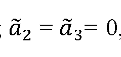
 obtain while keeping
 0, and finally, asymmetric pulse compression is performed by scanning to obtain while keeping x. A local gradient


 based optimization is performed to optimize all three variables simultaneously, using (
 , ) as an initial guess wherein a gradient of M with respect to is

 where Io is a reference intensity that is a normalization constant.
 [0085] In another aspect, the one or more correction algorithms include a wavefront distortion correction algorithm comprising an alternating optimization scheme including steps of: a) determining a target’s depth from a dispersion-compensated volumetric image by scanning a longitudinal direction z and selecting the depth where a 2D en face image yields a highest M. b) building a depth-resolved time-gated scattering matrix at a target’s
 depth zo from:
 where k°u1: and kj” are tranverse input and output wavenumbers, and
 are the longitudinal input and output wavenumbers, and c is the speed of light
 in the sample. c) building a matrix with each column containing the image from
 a single input wherein these single-input images, denoted as are built by:

 where denotes a transverse location on a zo plane. d) expand
 into Zernike polynomials:
 where is the vacuum wave number for the highest frequency ωmax considered.

 e) determine the gradient of AY with respect to the Zemike weights


 e) optimize AY; f) building a matrix , co) with each column containing the image
 from a single output wherein these single-output images, denoted as are built

 by:
by:
 g) determining the gradient of M with respect to the Zemike weights

 h) optimize AY; and i) alternate between optimizing ^and until A converges.


[0086J In another aspect, the one or more correction algorithms include a spatially varying wavefront distortion correction algorithm comprising:
a) dividing the image into small zones, each zone being corrected with its own correction phase maps wherein optimization of these zones’ images is non-convex; b) optimizing sharpness of a whole image is the input-output alternating optimization scheme; c) dividing the whole image into 2 x 2 smaller zones with equal sizes wherein these zones are slightly overlapped; d) optimizing each zone separately with Zemike weights of the whole image being an initial guess; e) after optimization, further dividing each zone into 2 x 2 smaller zones, where the Zernike weights of each big zone serve as the initial guesses for the smaller zones it contains f) repeating steps c) to e) until no further improvement of image quality is observed, wherein the number of optimized Zernike polynomials is also increased after each division step with the weights of newly added Zernike polynomials are initialized as zeros. g) Before the correction of each zone, performing a pre-processing step in which the time-gated reflection matrix
 kj", zo) updated by the correction phases of larger zones, is Fourier-transformed into a spatial basis truncated matrix S(r|°ut, r|fn, Zo) by:
 where S(k°ut, kj", zo) is a time-gated reflection matrix in spatial basis, F|°ut, F|°ut are output and input locations, respectively, where all scattering coefficients at F|°ut, F|°ut outside the zone are set to zero; and h) Fourier-transforming the spatial basis truncated matrix back to a wavenumber basis:
S(kf

 [0087] 2.2 Results
[0088] Figure 9a provides a schematic of conventional imaging and wavefront shaping, with wavefront modulated by lenses and spatial light modulators (SLMs) and using feedback from guidestars. Figure 9b-c illustrates the virtual spatiotemporal wavefront shaping approach, as described above. This approach not only combines all the strengths of the conventional methods but goes beyond them as schematically illustrated in Figure 9b-c, z. The hyperspectral scattering matrix of the sample was measured and used to virtually perform spatiotemporal focusing with high-speed Guidestar-free wavefront optimization for every isoplanatic patch, pulse compression, and refractive index mismatch correction. The focus digitally can be scanned to yield a phase-resolved 3D image of the sample with no depth-of-field trade-off. A progressive strategy with regularization to guide the nonconvex optimization toward the global optimum is developed. Without using liquid-immersion objective lenses, a depth-over-resolution ratio of 910 at one millimeter beneath mouse brain tissue is already achieved — the highest ratio reported in the literature (including all optical and all non-optical label- free methods). An ideal diffraction-limited resolution is attained when the signal is reduced by over ten-millionfold due to multiple scattering, where RCM, OCT, and OCM all fail to resolve any feature of a resolution target. The ideal transverse and axial resolutions across a depth of field of over 70 times the Rayleigh range deep inside a dense colloid is maintained. This approach translates deep-tissue imaging into a computational reconstruction and optimization problem.
[0089] 2.2.1 Scattering matrix tomography
[0090] The scattering matrix [59, 60] encapsulates the sample’s complete linear response (Figure 9b-c (zz)): any incident wave is a superposition of plane waves
 over momentum kin and frequency co, and the resulting outgoing wave

 is given by the scattering matrix
 through
 . The angular summations are restricted to
 in a background medium with speed of light c/nbg.

 [0091] After measuring a subset of the scattering matrix, the sample’s response is digitally synthesized to virtually perform tailored measurements in space-time for customized spatiotemporal inputs. As illustrated in Figure 9b-c, Hi, summing over incident angles kin with coefficient creates an incident beam spatially focused at rjn, forming an input

 spatial gate; summing over outgoing angle kout with coefficient ) yields the scattered field
 EOut(r, co) given a virtual detector at position r, forming an output spatial gate; summing over frequency co with a constant phase creates an incident pulse that arrives at nn at time t = 0, forming a temporal gate. Given a spatiotemporal focus arriving at r;n at t = 0, the scattered field is therefore
 . Aligning the input spatial gate with the output spatial gate
 (setting nn = r) and then aligning the temporal gate with the spatial gates (evaluating Eout at time t = 0), the triply-gated scattering amplitude of the sample at position r is obtained, which is denoted as as

Digitally scanning r forms a phase-resolved 3D image of the sample where the three gates align at every point (Figure 9b-c, /). This enables high lateral resolution and high axial resolution across a wide field of view and large depth of field, with no restriction on any focal plane. The non-uniform fast Fourier transform [61] is used to efficiently evaluate these summations and the spatial scan. This is the minimal form of “scattering matrix tomography” (SMT).
[0092] MT efficiently suppresses multiple scattering. The single— scattered field at output kout for an input from kin is given by the Born approximation as proportional to
 namely the q = kout - kin component of the 3D Fourier transform of the sample’s permittivity contrast profile r|(r) [62, 21, 22], Such single-scattering contributions add up in phase in Eq. (1) to form the image, similar to an inverse Fourier transform from i](q) to r](r); meanwhile, the multiple-scattering contributions add up with quasi-random phases. Therefore, the triple summations over co, kout, and kin boost the single-to- multiple-scattering ratio
 enable imaging even when multiple scattering is orders of magnitude stronger than single scattering in the raw data 5(kOut, kin, co).
 [0093] Beyond scattering suppression, SMT also allows customized spatial and spectral corrections. The frequency dependence of the refractive index (i.e., dispersion) in the optical elements of the system and the sample creates a frequency-dependent phase that misaligns and broadens the temporal gate. SMT can overcome dispersion using a spectral phase 0(a), acting as a virtual pulse shaper (Figure 9b-c, iv). The refractive index mismatch between the sample medium (e.g., biological tissue), the far field (e.g., air), and the coverslip (if there is one) refracts the rays and degrades the gates. By using the appropriate propagation phase shift in each medium, SMT can achieve an ideal focus even in the presence of refraction, effectively creating a virtual dry objective lens that perfectly focuses inside any refractive index at any depth (Figure 9b-c, v) without expensive hardware or liquid immersion.
[0094] Importantly, SMT also enables additional wavefront modulations that can convert the scattered light to focused light. This is achieved through angle-dependent phase profiles Φin (kj") and out that act as two virtual SLMs, one for the incident wave and one for the outgoing wave (Figure 9b-c, vz). These phase profiles can overcome both the multiple scattering from the sample and the aberrations from the optical elements in the measurement setup. Different isoplanatic patches and distinct spectral components can use different phase maps Φin and ΦOut, as in Φin = Φin . The
 general form of SMT reads

[0095] By measuring the hyperspectral reflection matrix of a mirror and subtracting the phase of its diagonal elements from that of the sample reflection matrix, the dispersion and the input aberrations is removed in the optical system.
[0096] To further overcome the sample dispersion, output aberration in the optical system, and the scattering from the heterogeneous sample, and are determined by

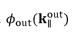
 maximizing an image quality metric M. Here, M = £r /sMT(r)'n SMTW/ with /o being a constant, $(co) a third-order polynomial of frequency, and ^in/out expanded in Zernike polynomials is used. This is a nonconvex optimization problem, and adopting a suitable strategy is crucial to stay away from poor local optima. The quadruple summation over frequency, incident angle, outgoing angle, and position is very effective in smoothing the optimization landscape and eliminating poor local optima. Regularization is important to avoid overfitting, which is accomplish by choosing the appropriate number of Zernike polynomials. To account for the wavefront variation across isoplanatic patches without overfitting, a progressive bisection strategy described is developed below. In doing so, the optimization is robust and achieves high performance regardless of the detailed parameter choice and the initial guess. All results here use zero phase correction as the initial guess for optimization.
[0097] Measuring the hyperspectral scattering matrix S(kout, k;n, co) only requires input kin and output kout in the far field; there is no need to place detectors, guidestars, or fluorescence labels at the positions r to be imaged. It is not necessary to measure the full scattering matrix: one can restrict the triple summation of Eqs. (1)— (2) to any subset of the input, of the output, and of the frequencies, in any basis (angular or spatial [48], spectral or temporal), offering great flexibility on the measurement scheme. In the experiment below, input and output angles on the same side (namely, S is the reflection matrix R) within a numerical aperture (NA) of 0.5 are measured. As SMT performs wavefront shaping digitally, the measurement can use angular [64] or frequency [65, 66] scans at high speed, limited only by the camera frame rate (which can go beyond MHz for commercial cameras, orders of magnitude faster than the fastest SLMs). The subsequent wavefront optimization requires no additional measurement and outpaces SLM-based optimization even more. The absence of spatial or temporal focus during measurement prevents photodamage to the sample and also avoids localized saturation of the camera to allow for a higher signal-to-noise ratio. The synthesized pulse is concentrated at the target arrival time instead of spreading out across different times, providing another signal -to-noise- ratio advantage similar to that of frequency-domain OCT over time-domain OCT. The triple summation of SMT additionally suppresses uncorrelated noises in the scattering matrix data.
|0098] 2.2.2 Experimental
 [0099] Off-axis holography is employed to measure the scattered field EOut(kOut> 60 using a CMOS camera (Photron Fastcam Nova S6) to capture 64,000 columns of the reflection matrix per second, a dual-axis galvo scanner (ScannerMAX Saturn 5B) to scan the incident angle kin, a tunable laser (M Squared SolsTiS 1600) to scan the frequency oo, with a dry objective lens (Mitutoyo M Plan Apo NIR 100X, NA = 0.5) (Figure 10). The power onto the sample ranges from 0.02 mW to 0.2 mW. Around 200 wavelengths from 740 nm to 950 nm, 2,900 outgoing angles, and 3,900 incident angles within the NA, for a 50x50 pm2 area are measured. The detection sensitivity, currently limited by the residual reflection from the objective lens, is 90 dB.
10100] 2.2.3 2D Imaging
[0101] First, the 8th group (whose sixth element has a bar width of 1.1 pm) of a 1951 USAF resolution target underneath 0.98 mm of mouse brain tissue (Figure I la) is imaged. The hyperspectral reflection matrix allows us not only to perform SMT but also to synthesize existing reflection-based imaging methods: restricting the frequency summation of Eq. (2) to one frequency yields a synthetic RCM image without time gating (Figure 1 lb); restricting the angular summations of Eq. (2) to small angles ( NA = 0. lis used here) yields a synthetic OCT image where the spatial beam is weakly focused to provide a larger depth of field (Figure 11c); for the synthetic OCM image (Figure 1 Id), sum over all frequencies and all angles. The imaging plane is chosen to maximize the total signal. To create optimal RCM, OCT, and OCM images as a comparison to state-of-the-art, corrections for the dispersion and input aberration of the optical system are included, as well as the dispersion of the sample. Despite these enhancements, none of the three methods can reveal any group-8 element due to the overwhelming scattering from the mouse brain tissue.
10102] The SMT image also corrects the air-glass-sample index mismatches and incorporates optimized wavefronts that correct the multiple scattering from the sample and the output aberration of the optical system. Start by optimizing the image quality metric over the full 50x50 pm2 image with the same pin out; the summation over the many image pixels suppresses local oscillations of the objective function and makes the optimization problem more convex. As the field of view (50 x 50 pm2) is much larger than the isoplanatic patch size at this depth, the spatial dependence of the optimal
 wavefront is significant. Therefore, the image is progressively bisected and c|)in/out is optimized in the divided zones using the previous c|)m /out as the initial guess until no further improvement is observed. The gradient-based optimization algorithm is used to perform local optimizations, using up to 275 Zernike polynomials in each of the 64 zos. The resulting (j)m and ^out are shown in Figure I lf; note out(k||) =# in(— k||) since the former includes the optical-system aberration. With these corrections, SMT can image the USAF target with near perfection down to the smallest element of group 8 (Figure He).
[0103] To quantify the imaging performance, the point spread function (PSF) is obtained by evaluating Eq. (2) with a variable output position r given a fixed input position rin: PSF(r) = I(r, rjn). V. For RCM, OCT, and OCM (Figures 11 g— i), the PSF has no discernible peak near r = nn, indicating a complete failure to image. The speckled OCM PSF averages to be 70 dB below the peak PSF of a mirror without the brain tissue (Figure I lk), so the signal (which is buried beneath the speckled background and not visible here) has been reduced by at least ten-million-fold due to multiple scattering. The PSF of SMT (Figure 1 Ij) exhibits a sharp peak at r = rin with 7-times the height of the tallest speckle in the background, showing that the depth limit (where the signal equals the background) of SMT is not reached yet. The peak of the SMT PSF is 70 times higher than the averaged OCM PSF, indicating that the input and output wavefront corrections and the index-mismatch correction increase the signal by at least 70-fold. The SMT peak’s full width at half maximum (FWHM) is 1.08 pm, close to the 0.93 pm FWHM of the mirror PSF, demonstrating diffraction limited resolution despite the overwhelming multiple scattering. The depth-over-resolution ratio is 910 here.
[0104] 2.2.4 Volumetric Imaging
[0105] Next, 3D tomography of a dense colloid consisting of high-index titanium dioxide (TiO2, refractive index 2.5) nanoparticles dispersed in polydimethylsiloxane (PDMS, refractive index 1.4) is performed. The nanoparticles (Sigma-Aldrich, 914320) have a typical diameter of 500 nm, and the transport mean free path is estimated to be 1 mm. A 50 * 50 x 110 pm3 volume inside the colloid at 1.2 mm depth is imaged. SMT creates a detailed 3D image of all the nanoparticles in the volume (Figure 12a). Zooming onto individual particles (Figures 12e and i), the lateral FWHM resolution is
 found to be submicron and the axial FWHM resolution close to the theoretical limit of 1.28 pm for the 206 nm bandwidth here, across the whole volume. This volume spans 73 times the Rayleigh range ZR = nsamW(7rNA2) - 1.5 pm (with center wavelength 0 = 840 nm and nsam = 1.4 for PDMS), consistent with the theoretical prediction.
[0106] For comparison, synthetic RCM, OCT, and OCM images are constructed (Figures 12b- d). Longitudinal and transverse slices are shown in Figures 12e-h and Figure 12j. The OCT and OCM images have the depth of the spatial gate fixed on one focal plane at z = 1, 220 pm. As in the 2D case, complete dispersion compensation and the input aberration correction of the optical system are included. In order to quantitatively compare the z coordinate across different methods, the indexmismatch correction in these three images is also included. However, RCM and OCT still cannot image any of these nanoparticles at this depth. OCM can only image some of the nanoparticles near the focal plane, with compromised image quality.
[0107] 2.3 Discussion and Conclusion
[0108] Beyond the already superior performance of SMT, there are avenues for further advances. The dispersion compensation and the wavefront correction are separated; future work can account for the frequency dependence of the optimal wavefront to utilize the multiple-scattering waves more efficiently. One may use the lower-resolution but deeper images from forward scattered photons to initiate optimization for high-resolution imaging at deeper depths. Recent advances in the fast computation of scattering matrices can enable numerical experiments to explore SMT optimization strategies.
[0109] SMT can work with reflection, transmission, remission, or a combination of them (such as a 4Pi microscope), in any basis. One may use the phase information of ipsm for digital staining and to resolve small nm-scale displacements for neuro imaging. One may incorporate polarization gating to select birefringent objects such as directionally oriented tissues. The hyperspectral scattering matrix can additionally resolve spectral information of the sample, such as the oxygenation of the hemoglobin.
 [0110] Additional details are found in Zhang Y, Dinh M, Wang Z, Zhang T, Chen T, Hsu CW. Deep imaging inside scattering media through virtual spatiotemporal wavefront shaping. arXiv preprint arXiv:2306.08793. 2023 Jun 15; the entire disclosure of which is hereby incorporated by reference
[0111] 3. Inward-outward progression
[0112] In another aspect, a system for improving image quality in an imaging system is provided. Advantageously, the system applies inward-outward progression to achieve image improvements. Referring to Figure 8, system 100 includes a light source 103 configured to generate an input light signal varied over a predetermined frequency range. The system also includes an optical subsystem 14 that splits the input light signal into an incident light signal and a reference light signal and directs the incident light signal to a sample such that an output light signal includes light scattered from or transmitted through the sample, with the incident light signal varied over a predetermined range of incident angles. A camera is configured to receive the output light signal and the reference light signal and form an output image of a field of view. The system includes a computing device 120 configured to preprocess the output image to an initial in-out input image by performing a first singular value decomposition (SVD) to remove multiple scattering. The computing device 120 identifies a brightest location in the initial in-out input image, locates an initial optimization zone around the brightest location, performs spatial basis truncation, and then uses input-output alternating (IOA) optimization to optimize correction phases:
 out(kr) = Sn C°Ut2n(kH, where the c,1'1 and c°ut are Zernike weights, k}|nis the in-plane wavevector component of the incident light, and k^ut is the in-plane wavevector component of the scattered or output light, Zn is a wavefront of an nth Zernike polynomials, n is an integer label. The Zernike weights initially are for the entire field of view. The computing device iteratively shrinks the optimization zone and performs spatial basis
 truncation and IOA optimization for each progressively smaller zone using more Zemike polynomials than the initial optimization zone, where the c}” and c°ut of a previous zone are initial parameters for the current zone. This shrinking of zones is repeated until a zone’s image attains a predefined sharpness. The computing device then iteratively expands the optimization zone outward by applying optimized correction phases (Zemike weights), ensuring that each newly included zone is optimized by performing additional IOA optimization steps, thereby progressively enhancing the image quality across the entire image. Finally, the system stitches the zones together to form a complete image of the field of view.
10113] 3.1 Overview
[0114] Inward progression involves identifying the brightest zone in the image. This includes performing spatial basis truncation to limit the optimization to the relevant zones of the image. The process iteratively shrinks the zone and performs input-output alternating (IO A) optimization with increased correction detail using more Zemike polynomials. In a refinement, the spatial basis truncation involves converting the time-gated reflection matrix to spatial basis using a Fourier transform. The matrix elements outside the zone of interest are set to zero, and the truncated matrix is then converted back to angular basis for focused optimization.
10115] Out outward progression involves using the correction phases from the brightest zone to optimize surrounding zones. Singular Value Decomposition (SVD) can be performed on the timegated reflection matrix to remove multiple scattering background. The optimized correction phases are iteratively applied to further zones to enhance.
[0116] Typically, the images input to inward-outward progression are preprocessed with IOA optimization and spatial basis truncation and SVD for multiple scattering.
[0117] 3.2. IOA optimization and spatial basis truncation
[0118] The purpose of IOA optimization and spatial basis truncation is to iteratively optimize the correction phases for input and output wavefronts in an imaging system to improve the image
 quality by removing distortions caused by multiple scattering and other aberrations. By alternating between input and output optimization and using Zernike polynomials to parameterize the correction phases, the process aims to find the best possible correction phases that maximize the figure of merit M, which is a measure of image quality. This step is crucial for achieving high-resolution, high-quality images in environments where wavefront distortions are significant, such as in biological tissues or other highly scattering media. The spatial basis truncation ensures that the optimization is focused on the relevant zones of the image, further enhancing the accuracy and efficiency of the correction. This step starts from the time-gated reflection matrix ) . Each row is one output with
 wavenumber 1, each column is one input with wavenumber . The optimization finds the
 correction phases
 and for each input and each output. The corrected image is
 built from the by


The correction phases are parameterized using Zernike polynomials
 and
and
 and are the weights ofthe nth Zernike polynomials, Z„
 is the wavefront of the nth Zernike polynomials. The number of Zernike polynomials is a free parameter that should be sufficient to capture fast-varying wavefront distortion.
Before optimization, if the image is only a small zone within the field of view, perform spatial basis truncation to remove signals outside the zone. First, convert. First, convert to spatial
 basis using a Fourier transform:


For all outside of the zone of interest, set then convert back to angular

 basis to obtain the reflection matrix of the zone

 where Nin, Nout are the number of inputs and outputs. (When the IOA optimization is explained, is used in the equations but it should be understood that when optimizing a small zone, the matrix will

Perform input optimization to find c^n, given the initial guess
 =
=
 = ). Precompute the single-input
 complex images:
 such that

[0119] In another aspect, the computing device 120 is further configured to optimize a figure of merit M for input optimization and output optimization. The figure of merit M is a function of
 and examples include a normalization constant). The
 gradient of M with respect to
 is:
is:

M is optimized using a gradient-based optimization algorithm. Then, perform output optimization to find . Precompute the single-output complex images: such that
 and c is the result of the previous input optimization. The gradient of M with respect to
 is:
is:

Using this gradient,
 t is found by a gradient-based optimization algorithm. Then, return to find
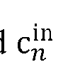 using the same process described previously, with the initial guess being the from the earlier step.

 Subsequently, find c°utfollowing the same method, using the c°Lltfrom the prior step as the initial guess. In essence, the result of each input optimization serves as the initial guess for the next input optimization. This process of alternating between input and output optimization is repeated until the figure of merit M converges.
[0120] In another aspect, computing device 120 is further configured to: precompute single-output complex images: such that
 and Cn is a result of the previous input optimization; return to find c,1" using the same process, with the initial estimate being the cj from the previous step; find c°utfollowing the same method, using the c°utfrom the prior step as the initial value, where the result of each input optimization, serves as the initial estimate for a next input optimization, the process of alternating between input and output optimization is repeated until the figure of merit M converges.
[0121] 3.3. SVD for multiple scattering removal
|0122] The purpose for multiple scattering removal is to enhance image quality by removing the effects of multiple scattering, which manifests as a speckled background in images taken through scattering media. By applying Singular Value Decomposition (SVD) to the time-gated reflection matrix, the method isolates and removes small singular values that correspond to multiple scattering contributions. Retaining only the large singular values, which represent the stronger single scattering signals, allows for a clearer, more accurate image. In a refinement, the singular value decomposition includes setting a threshold value to differentiate between small singular values corresponding to multiple scattering and large singular values corresponding to single scattering and removing singular values below the threshold to eliminate multiple scattering contributions.
 [0123] In another aspect, computing device 120 is configured to convert the optimized matrix back to the angular basis, resulting in a reflection matrix that highlights single scattering signals and reduces noise from multiple scattering, thereby improving the overall image resolution and quality. In this step, the time-gated reflection matrix S(k[j>ut, kj", z0) is converted to spatial basis S(r|°ut, rj n, z0) by doing Fourier transform on each column and each row of
 z,, ):

Then, SVD is performed on S(r|°ut, F|jn, z0):
 with Af is the rank of S(r|°ut, rj 11 , z0). Inside scattering media, at moderate depths, the single scattering signal is significantly stronger than the multiple scattering (which manifests on the image as the speckled background). So, to remove the multiple scattering background, remove small singular values and keep only the large ones. The number of kept singular values TV’ is a free-to-choose parameter.
[0124] The reflection matrix after SVD is:

Then, this matrix is converted back to angular basis:
 where Vin, Vout are the number of inputs and outputs.
[0125] 3.4. Inward progression
[0126] In another aspect, the output image of a field of view is processed by input-output alternating (IOA) optimization followed by a first SVD. In a refinement, the IOA optimization involves precomputing single-input and single-output complex images for each input and output wavefront, constructing a total image intensity from the precomputed images, and maximizing an
 image quality metric The purpose of the inward progression is to incrementally refine the image quality by focusing on and optimizing the brightest zone, gradually shrinking the zone while increasing the correction detail using more Zernike polynomials. This process ensures high-quality wavefront correction phases for the central region, which can then be used as accurate initial guesses for optimizing neighboring regions.
[0127] Before starting inward progression, perform SVD to remove multiple scattering, focusing only on the brightest zone within the field of view and allowing the removal of targets outside this zone. Therefore, the number of retained singular values N' can be relatively small compared to the rank N of the reflection matrix. The inward progression is then performed on the matrix-after-SVD

[0128] Referring to Figure 14, after SVD, use IOA optimization to optimize the entire image, identify the brightest spot, and locate a small zone around it. Perform spatial basis truncation and IOA optimization on this selected zone, using the cj" and c°ut values from the whole image as the initial guess. Next, shrink the zone and repeat the spatial basis truncation and IOA optimization for this smaller area, employing more Zernike polynomials. Use the c”1 and c°ut values from the previous zone as the initial guess. Continue this process of shrinking, spatial basis truncating, and optimizing until the image quality of the zone is satisfactory. With each iteration, increase the number of Zernike polynomials.
[0129] Referring to Figure 15, after the inward progression, the small region around the brightest spot will have high-quality wavefront correction phases Φin (k||n) = <p ward (k}|n ) and out(k°ut) = ouTard(kjj>ut) which serve as accurate initial guesses for the neighboring regions.
[0130] 3.5. Outward progression
[0131] The purpose of outward progression is to systematically optimize image quality across all zones by using the correction phases of the brightest zone as initial guesses for surrounding areas.
 This iterative process ensures that wavefront distortions are minimized throughout the entire image, leading to high-resolution, high-quality imaging.
|0132] Referring to Figure 16, outward progression involves using the correction phases of the brightest zone to optimize the surrounding zones and subsequently applying these optimized phases to further zones. Initially, a second Singular Value Decomposition (SVD) is performed; in contrast to the first SVD, where both the multiple scattering background and distant targets were removed, the second SVD focuses solely on removing the multiple scattering background, requiring more singular values to be retained. The correction phases of the brightest zone are applied to the new reflection matrix after the second SVD, providing good initial guesses for the regions around the brightest zone, which only need minor improvements.
|0133] Referring to Figure 17, using the
 and values of the brightest zone as initial
 guesses, spatial basis truncation and IOA optimization are then performed on the four surrounding zones. These zones can be slightly larger than the brightest zone, and the number of Zemike polynomials used remains the same as in the last inward progression step.
[0134] The images of the brightest zone and the four surrounding zones are multiplied with stitching masks defined as maskzolie(x, y) = where xcenter ,
 center are the center coordinates of the zone, and IVX zone, W^ zone are the widths of the zone along the x and y directions. The images of these zones are then stitched together as /(x,y) =

[0135] Referring to Figure 18, the and values of the 4 inner boxes are next used as

 initial guesses to optimize the outer zones. If an outermost box spans two inner boxes, its initial guess is the average of the
 and
and
 values from both inner boxes. Apply stitching masks to these outer boxes and add them to the image:
 [0136] Referring to Figure 19, continue using the
 and c7°ut values of the optimized zones as initial guesses for the surrounding unoptimized zones, expanding the optimized area outward until no zones are left to optimize.
[0137] While exemplary embodiments are described above, it is not intended that these embodiments describe all possible forms of the invention. Rather, the words used in the specification are words of description rather than limitation, and it is understood that various changes may be made without departing from the spirit and scope of the invention. Additionally, the features of various implementing embodiments may be combined to form further embodiments of the invention.

Claims
1. A system for multi-spectral scattering-matrix tomography with snapshot hyperspectral acquisition, the system comprising: an interference microscope subsystem that includes a broadband light source that provides an input broadband light signal, the interference microscope subsystem being configured to generate a combined broadband interference image signal that includes interference patterns between a sample beam and a reference beam; and a hyperspectral imaging subsystem configured to acquire the interference patterns for a plurality of output channels and a plurality of light frequencies in a single shot collected with a highspeed camera; and a computing system configured to transform the interference patterns into scattering matrix coefficients across the plurality of output channels and the plurality of light frequencies of output.
2. The system of claim 1, wherein a region of interest of the high-speed camera is determined by a product of output spatial pixels and a number of frequencies in the plurality of light frequencies.
3. The system of claim 1, wherein the interference microscope subsystem further comprises an input beam module configured to provide and collimate the input broadband light signal, polarize it, and split it into an incident sample light signal and a reference light signal.
4. The system of claim 3, wherein the hyperspectral imaging subsystem further comprises: a spatial light modulator configured to deflect different parts of the combined broadband interference image signal into separated angle ranges; a lens array configured to collect different spatial regions in the separated angle ranges and form a sliced image at a focal plane of the lens array; a blazed grating configured to diffract light signals from the sliced image at different frequencies into different angles to form a dispersed light signal; and
 a lens system configured to collect the dispersed light signal and the high-speed camera positioned on a conjugate plane of the spatial light modulator to image the dispersed light signal.
5. The system of claim 4, wherein the interference microscope subsystem further comprises a sample beam module configured to focus the incident sample light signal onto the sample and scan over a sample plane.
6. The system of claim 5, wherein the sample beam module includes: a quarter wave plate through which the incident sample light signal and an output scattered light signal pass; an objective lens configured to focus a incident sample light signal on the sample plane; and a pinhole placed on a conjugate plane of the sample plane to truncate the output sample light signal and selectively allow outputs near an input location while blocking outputs distant from an incident focus location.
7. The system of claim 5, wherein a reference beam module includes: a reference mirror, a grating, and a pinhole; a quarter wave plate through which the reference light signal and a reflected reference light signal pass; and optical elements configured to match an optical path of the reference light signal to the optical path of the incident sample light signal.
8. The system of claim 7, wherein the reference beam module further comprises: a polarized beam splitter and a quarter wave plate configured to eliminate power loss during beam splitting, thereby providing a four-fold increase in power efficiency.
9. The system of claim 4, wherein the hyperspectral imaging subsystem includes: a first lens that provides different spatial regions in separated angle ranges through the lens array; and
 the high-speed camera configured to image the dispersed light signal, where the high-speed camera is placed on a conjugate plane of the spatial light modulator.
10. A method for multi-spectral scattering-matrix tomography with snapshot hyperspectral acquisition, the method comprising: combining a reflected reference light signal and an output sample light signal to form a combined broadband interference image signal, the reflected reference light signal and the output sample light signal include a plurality of frequencies; and applying a hyperspectral imaging scheme comprising steps of: directing the combined broadband interference image signal to a spatial light modulator, the spatial light modulator deflecting different image parts into separated angle ranges; collecting the different image parts in the separated angle ranges through a lens array to form a sliced image at a focal plane of the lens array; illuminating the sliced image on a blazed grating, the blazed grating diffracting light signals from the sliced image at different frequencies into different angles to form a dispersed light signal that include interference patterns; collecting the dispersed light signal by a lens system; imaging the dispersed light signal with a high-speed camera, the high-speed camera being placed on a conjugate plane of the spatial light modulator, wherein a region of interest of the camera is determined by a product of output spatial pixels and the number of frequencies in the plurality of light frequencies; calculating with a computing device scattering matrix coefficients across a plurality of output channels and the plurality of light frequencies comprising steps of: transforming the images collected by the camera into a plurality of interference patterns at different light frequencies; and
 process these interference patterns to calculate phase and amplitude of scattering matrix coefficients across the plurality of output channels and the plurality of light frequencies.
11. The method of claim 10, wherein the combined broadband interference image signal is created by: a) splitting an input broadband light signal into an incident sample light signal and a reference light signal, wherein the input broadband light signal includes a plurality of light frequencies; b) directing the incident sample light signal to focus onto a sample such that an output light signal scattered from the sample is generated, wherein a focal point of the incident sample light signal is varied over a predetermined range of areas; c) focusing the reference light signal onto a reference mirror through an optical path that matches the optical path of the incident sample light signal to form a reflected reference light signal; d) passing the reflected reference light signal through a grating which provides a constant wavevector shift for all frequencies; e) passing the reflected reference light signal through a pinhole used to select a first diffraction order signal from the grating while blocking other orders; and f) combining the reflected reference light signal and the output sample light signal to form a interference pattern.
12. The method of claim 11, where step a) is performed by an input beam subsystem, step b) is performed by a sample beam subsystem, steps c) through e) are performed by a reference beam subsystem, step f) is performed by an interferometry subsystem.
13. The method of claim 12, wherein the input beam subsystem includes: a broadband source that provides the input broadband light signal; a collimating lens that receives and collimates the input broadband light signal;
 a first polarized beam splitter linearly polarizes the input broadband light signal from the collimating lens; a second polarized beam splitter that splits the input broadband light signal into the incident sample light signal and the reference light signal; and a Fresnel rhomb positioned between the first polarized beam splitter and the second polarized beam splitter for adjusting a power ratio between the incident sample light signal and the reference light signal.
14. The method of claim 12, wherein the sample beam subsystem includes: an objective lens (OL) that focuses the incident sample light signal on the sample; a pinhole placed on the conjugate plane of a sample plane to truncate the output sample light signal, selectively allowing outputs near an input location while blocking outputs distant from an incident focus location; a MEMS scanner placed on the conjugate plane of a back focal plane of the objective lens, the MEMS scanner configured to scan a focused input over the sample plane; and a quarter wave plate through which the incident sample light signal and the output scattered light signal pass.
15. The method of claim 12, wherein the reference beam subsystem includes a quarter wave plate through which the reference light signal and the reflected reference light signal pass.
16. The method of claim 15, wherein the use of a polarized beam splitter and the quarter wave plate eliminates power loss during beam splitting, thereby providing a 4-fold increase in power efficiency.
17. The method of claim 12, wherein the interferometry subsystem includes a nonpolarized beam splitter that combines the reflected reference light signal and the output sample light signal.

18. The method of claim 10, wherein the hyperspectral imaging scheme is performed by a hyperspectral imaging subsystem.
19. The method of claim 18, wherein the hyperspectral imaging subsystem includes the spatial light modulator, a first lens that provides the different image parts in the separated angle ranges through the lens array, the blazed grating, the lens system, and the high-speed camera.
20. A system for multi -spectral scattering-matrix tomography comprising: a light source configured to generate an input light signal varied over a predetermined frequency range; an optical subsystem that splits the input light signal into an incident light signal and a reference light signal and directs the incident light signal to a sample such that an output light signal includes light scattered from or transmitted through the sample, with the incident light signal varied over a predetermined range of incident angles or incident spatial focusing locations; a camera configured to receive the output light signal and the reference light signal, wherein the reference light signal is directed at a constant angle with respect to the output light signal to allow for amplitude and phase calculation by off-axis holography; a computing device configured to: measure a total light signal as a coherent sum of the reference light signal and the output signal using the camera; collect the total light signal for each light frequency and each incident angle as collected total light signal data; calculate a reflection matrix or transmission matrix from the collected total light signal data; derive an image of the sample from the reflection matrix or transmission matrix by summing over angles and light frequencies; and apply one or more correction algorithms to the reflection matrix or transmission matrix to increase resolution and penetration depth, including dispersion compensation, wavefront distortion correction, and spatially varying wavefront distortion correction.

21. The system of claim 20, wherein the optical subsystem comprises: a beam splitter configured to split the input light signal into an incident light signal and a reference light signal; and a sample holder configured to hold a sample, wherein the incident light signal is directed to the sample such that an output light signal includes light scattered from or transmitted through the sample, with the incident light signal varied over a predetermined range of incident angles or incident spatial focusing locations.
22. The system of claim 20, wherein the computing device is configured to determine the reflection matrix or transmission matrix by Fourier transforming the collected total light signal data to form transformed collected total signal data and performing an inverse Fourier transform on a first- order region of the transformed collected total signal data to determine the amplitude and phase of the output signal.
23. The system of claim 1, wherein an image intensity is determined from:
 where:
/SMT is the image intensity as a function of position r in the sample; r is a position vector of a point in the sample; (kout, kin, co) is an element of the scattering matrix for an incidence channel with kin and a reflection channel with kout; kin is a wavevector of the incident light signal; kout is the wavevector of the output light signal;
0(co) is a spectral phase; c|)in is an input correction phase;
<|)out is an output correction phase; and
CO is the light frequency.

24. The system of claim 20, wherein the one or more correction algorithms include a dispersion compensation algorithm comprising: introducing a frequency-dependent phase shift 0(co) to the scattering matrix; precomputing an angular summation from:
 such that
 wherein 0(m) is determined by maximizing an image quality metric M:

S(kout, kjn, ω ) is the scattering matrix.
25. The system of claim 24, wherein the dispersion compensation algorithm further includes regularizing optimization by express 0(co) as a third-order polynomial,
 where ωio is a central frequency, and are dimensionless dispersion coefficients.

26. The system of claim 25, wherein to maximize AT while avoiding poor local optima, one variable at a time is optimized such that first a temporal gate is aligned with a spatial gates by scanning to obtain while keeping
 0, then symmetric pulse compression is performed by scanning to obtain
 while keeping
 and
and
 , and finally, asymmetric pulse compression is performed by scanning
 to obtain
 while keeping


27. The system of claim 26, further comprising performing a local gradient-based optimization to optimize all three variables simultaneously, using as an initial
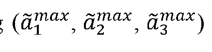 guess wherein a gradient of M with respect to is
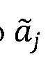
 where Io is a reference intensity that is a normalization constant.
28. The system of claim 20, wherein the one or more correction algorithms include a wavefront distortion correction algorithm comprising an alternating optimization scheme including steps of: a) determining a target’s depth from a dispersion-compensated volumetric image by scanning a longitudinal direction z and selecting the depth where a 2D en face image yields a highest M; b) building a depth-resolved time-gated scattering matrix at a target’s depth zo from:
 where kyut and k|" are tranverse input and output wavenumbers, and
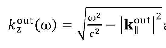 are the longitudinal input and output wavenumbers, and c is the speed of light
 in the sample; c) building a matrix Ψin from ) with each column containing the image from
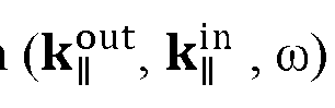 a single input wherein these single-input images, denoted as are built by:
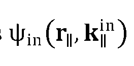

 where denotes a transverse location on a zo plane,
 d) expand
 into Zemike polynomials:
 is the vacuum wave number for the highest frequency considered;

 e) determine the gradient of M with respect to the Zemike weights

 e) optimize M f) building a matrix with each column containing the image from
 a single output k^ ut wherein these single-output images, denoted as are built by:
 .
.
 g) determining the gradient of M with respect to the Zernike weights :

 h) optimize A7/; and i) alternate between optimizing c,1" and c°ut until M converges.
29. The system of claim 20, wherein the one or more correction algorithms include a spatially varying wavefront distortion correction algorithm comprising: a) dividing the image into small zones, each zone being corrected with its own correction phase maps wherein optimization of these zones’ images is non-convex; b) optimizing sharpness of a whole image is the alternating optimization scheme; c) dividing the whole image into 2 x 2 smaller zones with equal sizes wherein these zones are slightly overlapped; d) optimizing each zone separately with Zemike weights of the whole image being an initial guess; e) after optimization, further dividing each zone into 2 x 2 smaller zones, where the Zernike weights of each big zone serve as the initial guesses for the smaller zones it contains f) repeating steps c) to e) until no further improvement of image quality is observed, wherein the number of optimized Zernike polynomials is also increased after each division step with the weights of newly added Zernike polynomials are initialized as zeros; g) Before the correction of each zone, performing a pre-processing step in which the timegated reflection matrix S(k°ut, k}", zo) updated by the correction phases of larger zones, is Fourier- transformed into a spatial basis truncated matrix S( rr. rr. Zot by:
 where S(k°ut, kj", zo) is a time-gated reflection matrix in spatial basis, F|°ut, F|°ut are output and input locations, respectively, where all scattering coefficients at F|°ut, F|°ut outside the zone are set to zero; and
 h) Fourier-transforming the spatial basis truncated matrix back to a wavenumber basis:

30. A system for improving image quality in an imaging system, the system comprising: a light source configured to generate an input light signal varied over a predetermined frequency range; an optical subsystem that splits the input light signal into an incident light signal and a reference light signal and directs the incident light signal to a sample such that an output light signal includes light scattered from or transmitted through the sample, with the incident light signal varied over a predetermined range of incident angles; a camera configured to receive the output light signal and the reference light signal and form an output image of a field of view; a computing device configured to: a) preprocess the output image to an initial in-out input image by performing a first singular value decomposition (SVD) to remove multiple scattering; b) identify a brightest location in the initial in-out input image, locate an initial optimization zone as an initial optimization zone around the brightest location, perform spatial basis truncation, and then use input-output alternating (IOA) optimization to optimize correction phases

 where the c,1" and c°ut are Zemike weights, kyni s the in-plane wavevector component of the incident light, and k^ut is the in-plane wavevector component of the scattered or output light,
 Zn is a wavefront of an nth Zernike polynomials, n is an integer label, initially, the Zernike weights are the for an entire field of view; c) iteratively shrink the optimization zone and perform spatial basis truncation and IOA optimization for each progressively smaller zone using more Zernike polynomials than the initial optimization zone where the c^n and c°ut of a previous zone are initial parameters for a current zone, wherein shrinking of zones is repeated until a zone’s image attains a predefined sharpness; d) iteratively expand the optimization zone outward by applying optimized correction phases (Zernike weights), ensuring that each newly included zone is optimized by performing additional IOA optimization steps, thereby progressively enhancing the image quality across the entire image; e) stitching zones together to form a complete image of the field of view.
31. The system of claim 30, wherein the output image of a field of view is processed by input-output alternating (IOA) optimization followed by a first SVD.
32. The system of claim 31, wherein the IOA optimization involves: precomputing single-input and single-output complex images for each input and output wavefront; constructing a total image intensity from the precomputed images; and maximizing an image quality metric.
33. The system of claim 31, wherein IOA optimization starts from a time-gated reflection matrix
 zo), where each row is one output with wavenumber k°ut, each column is one input with wavenumber kj" , the IOA optimization finds the correction phases c|)in (ky11) and <t>out(k|| ut) for each input and each output from which a corrected image is built from SO^. k^ Zo) by
 , wherein the
 correction phases are parameterized using Zernike polynomials.
34. The system of claim 33, wherein before IOA optimization: if the image is only a small zone within the field of view, perform spatial basis truncation to remove signals outside the zone by converting to spatial basis using a

 Fourier transform:
 for all F|°ut, F|} n outside of a zone of interest, set then convert back to angular basis
 to obtain the reflection matrix of the zone

 where Nin, Nout are the number of inputs and outputs, respectively.
35. The system of claim 34, wherein the computing device is further configured to: perform input optimization to find cj", given an initial estimate =

 precompute a single-input complex image: such that

36. The system of claim 35, wherein the computing device is further configured to optimize a figure of merit M for input optimization and output optimization.
37. The system of claim 36, wherein the figure of merit M is
 M = / (r||) In R^l (/0 is a normalization constant); a gradient of M with respect to c^1 is:
 a gradient of M with respect to c°ut is:

38. The system of claim 37, wherein the computing device is further configured to precompute single-output complex images:
 such that
 and c is a result of the previous input optimization; return to find c‘" using the same process, with the initial estimate being the cj" from the previous step; and find c°utfollowing the same method, using the c°utfrom the prior step as the initial value, where the result of each input optimization, serves as the initial estimate for a next input optimization, the process of alternating between input and output optimization is repeated until the figure of merit M converges.
39. The system of claim 31, wherein the computing device is further configured to: perform singular value decomposition (SVD) on a time-gated reflection matrix to isolate and remove small singular values corresponding to multiple scattering contributions; and retain only largest singular values representing stronger single scattering signals to produce a refined scattering matrix for further optimization.
40. The system of claim 31, wherein the singular value decomposition includes: setting a threshold value to differentiate between small singular values corresponding to multiple scattering and large singular values corresponding to single scattering; and
 removing singular values below the threshold to eliminate multiple scattering contributions.

Applications Claiming Priority (4)
| Application Number | Priority Date | Filing Date | Title |
|---|---|---|---|
| US202363472900P | 2023-06-14 | 2023-06-14 | |
| US63/472,900 | 2023-06-14 | ||
| US202463549045P | 2024-02-02 | 2024-02-02 | |
| US63/549,045 | 2024-02-02 |
Publications (2)
| Publication Number | Publication Date |
|---|---|
| WO2024259243A2 true WO2024259243A2 (en) | 2024-12-19 |
| WO2024259243A3 WO2024259243A3 (en) | 2025-03-27 |
Family
ID=93852741
Family Applications (1)
| Application Number | Title | Priority Date | Filing Date |
|---|---|---|---|
| PCT/US2024/034022 Ceased WO2024259243A2 (en) | 2023-06-14 | 2024-06-14 | Scattering matrix tomography with snapshot hyperspectral acquisition |
Country Status (1)
| Country | Link |
|---|---|
| WO (1) | WO2024259243A2 (en) |
Family Cites Families (4)
| Publication number | Priority date | Publication date | Assignee | Title |
|---|---|---|---|---|
| US9442015B2 (en) * | 2010-09-03 | 2016-09-13 | The Arizona Board Of Regents On Behalf Of The University Of Arizona | Snapshot spatial heterodyne imaging polarimetry |
| AU2012298253A1 (en) * | 2011-08-21 | 2014-04-03 | Mobile O.C.T Ltd. | Attaching optical coherence tomography systems onto smartphones |
| WO2019010507A1 (en) * | 2017-07-14 | 2019-01-17 | Wavesense Engineering Gmbh | Optical apparatus |
| US10219700B1 (en) * | 2017-12-15 | 2019-03-05 | Hi Llc | Systems and methods for quasi-ballistic photon optical coherence tomography in diffusive scattering media using a lock-in camera detector |
-
2024
- 2024-06-14 WO PCT/US2024/034022 patent/WO2024259243A2/en not_active Ceased
Also Published As
| Publication number | Publication date |
|---|---|
| WO2024259243A3 (en) | 2025-03-27 |
Similar Documents
| Publication | Publication Date | Title |
|---|---|---|
| US12052518B2 (en) | Multi-modal computational imaging via metasurfaces | |
| US11422503B2 (en) | Device and method for iterative phase recovery based on pixel super-resolved on-chip holography | |
| US12237094B2 (en) | Fourier ptychographic imaging systems, devices, and methods | |
| JP5721195B2 (en) | Optical characteristic measuring apparatus and optical characteristic measuring method | |
| CN106164784B (en) | Digital holography apparatus | |
| US7336353B2 (en) | Coding and modulation for hyperspectral imaging | |
| KR20210048951A (en) | Hyperspectral image sensor and image pickup apparatus including the same | |
| US11368608B2 (en) | Compressed sensing based object imaging system and imaging method therefor | |
| JP6192017B2 (en) | Digital holography device | |
| KR101916577B1 (en) | Method for imaging target object within media which bring about simultaneously scattering and aberration | |
| CN1688944A (en) | Off-axis illumination direct-to-digital holography | |
| WO2019025759A1 (en) | Coded aperture spectral imaging device | |
| US20230128254A1 (en) | Multi-spectral scattering-matrix tomography | |
| Hagen et al. | Using polarization cameras for snapshot imaging of phase, depth, and spectrum | |
| JP6984736B2 (en) | Imaging device and imaging method | |
| Degraux et al. | Compressive hyperspectral imaging by out-of-focus modulations and fabry-pérot spectral filters | |
| Petrov et al. | Terahertz multiple-plane phase retrieval | |
| Zhu et al. | Digital holography with polarization multiplexing for underwater imaging and descattering | |
| WO2021159084A1 (en) | Lattice light-sheet and fresnel incoherent correlation holography | |
| US12446780B2 (en) | Spectral domain-optical nonlinearity tomography device | |
| JP7591424B2 (en) | Incoherent holographic imaging device | |
| KR101332984B1 (en) | Hologram tomography apparatus and method thereof | |
| Liu et al. | Wavefront Line‐Scan Imaging Via a Single‐Pixel Detector | |
| Zhang et al. | Research on multi-band interferometric imaging based on spatially modulated full-polarization imaging system | |
| Dereniak | Infrared spectro-polarimeter |
Legal Events
| Date | Code | Title | Description |
|---|---|---|---|
| NENP | Non-entry into the national phase |
Ref country code: DE |