WO2024258862A2 - Mechanophore crosslinkers for tough, crosslinked polymers - Google Patents

Mechanophore crosslinkers for tough, crosslinked polymers Download PDF

Info

Publication number
WO2024258862A2
WO2024258862A2 PCT/US2024/033425 US2024033425W WO2024258862A2 WO 2024258862 A2 WO2024258862 A2 WO 2024258862A2 US 2024033425 W US2024033425 W US 2024033425W WO 2024258862 A2 WO2024258862 A2 WO 2024258862A2
Authority
WO
WIPO (PCT)
Prior art keywords
polymer
crosslinker
poly
polymeric material
acrylate
Prior art date
Legal status (The legal status is an assumption and is not a legal conclusion. Google has not performed a legal analysis and makes no representation as to the accuracy of the status listed.)
Ceased
Application number
PCT/US2024/033425
Other languages
French (fr)
Other versions
WO2024258862A3 (en
Inventor
Jeremiah A. Johnson
Thi Thu Suong NGUYEN
Abraham Herzog-Arbeitman
Stephen Craig
Shu Wang
Yunxin YAO
Zhen SANG
Current Assignee (The listed assignees may be inaccurate. Google has not performed a legal analysis and makes no representation or warranty as to the accuracy of the list.)
Massachusetts Institute of Technology
Duke University
Original Assignee
Massachusetts Institute of Technology
Duke University
Priority date (The priority date is an assumption and is not a legal conclusion. Google has not performed a legal analysis and makes no representation as to the accuracy of the date listed.)
Filing date
Publication date
Application filed by Massachusetts Institute of Technology, Duke University filed Critical Massachusetts Institute of Technology
Priority to EP24824012.9A priority Critical patent/EP4724416A2/en
Publication of WO2024258862A2 publication Critical patent/WO2024258862A2/en
Publication of WO2024258862A3 publication Critical patent/WO2024258862A3/en
Anticipated expiration legal-status Critical
Ceased legal-status Critical Current

Links

Classifications

    • CCHEMISTRY; METALLURGY
    • C08ORGANIC MACROMOLECULAR COMPOUNDS; THEIR PREPARATION OR CHEMICAL WORKING-UP; COMPOSITIONS BASED THEREON
    • C08FMACROMOLECULAR COMPOUNDS OBTAINED BY REACTIONS ONLY INVOLVING CARBON-TO-CARBON UNSATURATED BONDS
    • C08F257/00Macromolecular compounds obtained by polymerising monomers on to polymers of aromatic monomers as defined in group C08F12/00
    • CCHEMISTRY; METALLURGY
    • C08ORGANIC MACROMOLECULAR COMPOUNDS; THEIR PREPARATION OR CHEMICAL WORKING-UP; COMPOSITIONS BASED THEREON
    • C08FMACROMOLECULAR COMPOUNDS OBTAINED BY REACTIONS ONLY INVOLVING CARBON-TO-CARBON UNSATURATED BONDS
    • C08F283/00Macromolecular compounds obtained by polymerising monomers on to polymers provided for in subclass C08G
    • C08F283/12Macromolecular compounds obtained by polymerising monomers on to polymers provided for in subclass C08G on to polysiloxanes
    • CCHEMISTRY; METALLURGY
    • C08ORGANIC MACROMOLECULAR COMPOUNDS; THEIR PREPARATION OR CHEMICAL WORKING-UP; COMPOSITIONS BASED THEREON
    • C08LCOMPOSITIONS OF MACROMOLECULAR COMPOUNDS
    • C08L2312/00Crosslinking

Definitions

  • Polymer networks including elastomers, hydrogels, and various class of plastics, are widely used in applications from commodity materials to soft robotics and tissue engineering.
  • a consistent need is to control their mechanical behaviors, including wear resistance and durability. It remains a challenge to independently tune, for example, the fracture toughness of these materials to program their lifespan without varying other properties such as stiffness, as both stiffness and toughness derive from the nature of the network cross-links (which may be covalent or non-covalent) and usually trend in opposite directions with crosslink density (see Thomas, J. Polym. Sei. 18, 177-188 (1955)).
  • TCBs di-functional cyclobutanes
  • TCBs tetra-functional cyclobutanes
  • Polymers constructed through use of TCB endlinkers can display either substantially increased toughness or reduced toughness relative to traditional networks, depending on the fine details of the TCB mechanophore substituents.
  • a cross-linked polymeric material comprising: a polymer; and a crosslinker, wherein the crosslinker comprises a cyclobutane moiety.
  • the polymer is end-crosslinked by the crosslinker.
  • the crosslinker is a vulcanizer, and the polymer is randomly cross-linked by the vulcanizer.
  • the polymer comprises a polyolefin, a polystyrene, a polycarbonate, a polyurethane, a polyalkylene oxide, a polyurea, a silicone, a poly(meth)acrylate, and a rubber material.
  • the polymer comprises a polyolefin selected from polyethylene and polypropylene.
  • the polymer comprises a polystyrene.
  • the polymer comprises a polyalkylene oxide selected from polyethylene oxide, polypropylene oxide, and copolymers thereof.
  • the polymer comprises a silicone selected from poly(dimethylsiloxane-co-methylvinylsiloxane), poly(dimethylsiloxane-co- aminopropylmethylsiloxane), and poly(dimethylsiloxane-co-methylhydrosiloxane).
  • the polymer comprises a poly(meth)acrylate selected from poly(n-butyl acrylate-co-pentafluorophenyl acrylate) and poly(n-butyl acrylate-co-n- acryloxysuccinimide).
  • the polymer comprises a rubber material selected from polyisoprene and polybutadiene.
  • the crosslinker comprises a cyclobutane moiety having two points of attachment to end groups of the polymer backbone. In some embodiments, the crosslinker comprises a cyclobutane moiety having four points of attachment to end groups of the polymer backbone.
  • the crosslinker comprises a moiety having a formula selected from:
  • each represents a point of attachment to an end of the polymer backbone.
  • a method of manufacturing a crosslinked polymeric material comprising: a) providing a polymer in solution; b) combining the solution of the polymer with a crosslinker, wherein the crosslinker comprises a cyclobutane moiety; and c) reacting the polymer with the crosslinker to produce the crosslinked polymer material.
  • the polymer is end-crosslinked by the crosslinker.
  • the crosslinker is a vulcanizer, and the polymer is randomly cross-linked by the vulcanizer.
  • the polymer is a polyolefin, a polystyrene, a polycarbonate, a polyurethane, a polyalkylene oxide, a polyurea, a silicone, a poly(meth)acrylate, and a rubber material.
  • the polymer comprises a polyalkylene oxide selected from polyethylene oxide, polypropylene oxide, and copolymers thereof.
  • the polymer is a polyolefin selected from polyethylene and polypropylene.
  • the polymer is a polystyrene.
  • the polymer is a silicone selected from poly(dimethylsiloxane-co-methylvinylsiloxane), poly(dimethylsiloxane-co- aminopropylmethylsiloxane), and poly(dimethylsiloxane-co-methylhydrosiloxane).
  • the polymer is a poly(meth)acrylate selected from poly(n-butyl acrylate-co- pentafluorophenyl acrylate) and poly(n-butyl acrylate-co-n-acryloxysuccinimide).
  • the polymer is a rubber material selected from polyisoprene and polybutadiene.
  • the polymer comprises two end-groups, and the end-groups comprise reactive moieties.
  • each reactive moiety is independently selected from an azide, an alkyne, a diazirine, a thiol, a silane, a carboxylic acid, an amine, an alcohol, an ester, and a maleimide.
  • the crosslinker comprises a cyclobutane moiety having two reactive moieties. In some embodiments, the crosslinker comprises a cyclobutane moiety having four reactive moieties.
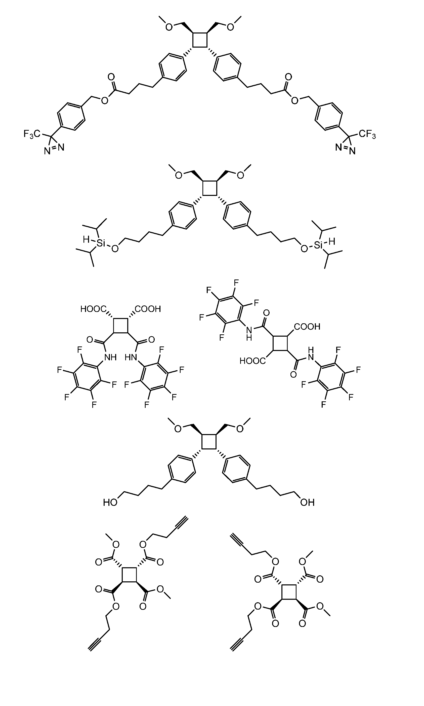
  • the crosslinker is a compound selected from:
  • a crosslinked polymer produced by a method disclosed herein.
  • a method of toughening a polymer network comprising incorporating a crosslinker disclosed herein into the polymer network.
  • FIG. 1 shows cyclobutane (square)-crosslinked polymers undergo force-induced cycloelimination, which leads to material toughening.
  • FIG. 2 shows crosslinking by transesterification.
  • FIG. 3 shows exemplary methods for network formation.
  • FIG. 5 shows results of crosslinking according to the method of FIG. 4.
  • FIG. 11 summarizes cyclobutene crosslinkers used according to certain examples disclosed herein.
  • FIG. 13 shows a crosslinking reaction using a CB tetraester crosslinker.
  • FIG. 14 shows results of crosslinking according to the method of FIG. 13.
  • FIG. 15 shows a crosslinking reaction using a CB C2ester crosslinker.
  • FIG. 16 shows results of crosslinking according to the method of FIG. 15.
  • FIG. 18 shows results of crosslinking according to the method of FIG. 17.
  • FIG. 19 shows results of crosslinking according to the method of FIG. 17.
  • FIG. 20 shows a crosslinking reaction using a CB amide crosslinker.
  • FIG. 21 shows results of crosslinking according to the method of FIG. 20.
  • FIG. 22 shows a control junction, and construction of a control end-linked network, Control-G.
  • FIG. 23 shows end-linked networks containing novel tetrafunctional cyclobutane (TCB) mechanophores with differing stress-dependent reactivity.
  • TBC tetrafunctional cyclobutane
  • FIG. 24 shows computed barriers to TCB [2+2]cycloelimination, TCB alkyl ester C- O heterolysis, and homolytic C-C bond scission in Control-G networks as a function of applied force. All [2+2]cycloelimination barriers were calculated under cis 1,2 stress regiochemistry. The C-0 heterolysis barriers shown were calculated under 1,3 stress regiochemistry.
  • FIG. 25 shows simulated CB-C2 model junction mechanochemical reaction barriers.
  • FIG. 26 shows junction analogs modeled herein, showing energetically favored and disfavored cleavage pathways.
  • FIG. 27 shows a CB-C 1 junction mechanochemical simulation.
  • FIGS. 28A-28D show mechanical properties of TCB versus Control gels.
  • FIG. 28A Young’s moduli, demonstrating similar cross-link densities and network structures.
  • FIG. 28B Representative full uniaxial stress-strain curves for Control-G (grey, square), CB-C2- G (blue, side-on triangle), CB-C1-G (gold, end-on triangle).
  • FIG. 28C Tensile toughness versus strain at break for each gel.
  • FIG. 28D Tearing energy versus the critical stress for crack propagation of notched gels. Box plots show distribution of data points; the white bar shows the median value, the black bar shows the mean value.
  • FIGS. 29A-29B show: (FIG. 29A) a schematic of crack propagation through a network with regioselective ring-opening injunctions (long contiguous strands highlighted); (FIG. 29B) Schematic of crack propagation in networks with unselective junctions that produce dangling ends under stress (dangling ends highlighted).
  • FIG. 30 shows a CB-ether junction and simulated mechanochemical reaction barriers. Top: structure of CB-ether junction. Middle: simulated barriers to cycloelimination and C-0 heterolysis under external force. Bottom: mechanochemical reactions simulated.
  • FIGS. 31A-31C show effects of junction cleavage regioselectivity on fracture behavior.
  • FIG. 31 A Simulated junctions and allowed cleavage reactions. Constructive cleavage produces contiguous strands; strand cleavage and arm dissociation produce dangling ends.
  • FIG. 3 IB Simulated fracture behavior of networks composed of junctions from C; dark lines show mean stress of 10 simulated networks, shaded regions are ⁇ 1 standard deviation).
  • FIG. 31C Comparison of networks with typical inert junctions (left) and regioselective mechanophore junctions (right) showing decoupling of bulk vs. crack-tip topology.
  • FIG. 32 shows the specific energy absorptions of polystyrene thermoplastic (black, square), control polystyrene network (red, circle), and CB polystyrene network (blue, triangle) versus particle impact velocity.
  • FIG. 32 bottom shows the specific energy absorptions measured for two different batches of these control and CB networks (pink and blue bars, respectively).
  • FIG. 33 shows laser confocal images of polystyrene thermoplastic (left), control polystyrene network (middle), and CB polystyrene network (right) thin films after particle impact at two initial impact velocities: 350 m/s (top row) and 750 m/s (bottom row).
  • FIG. 34 shows the images of control polystyrene network and CB polystyrene network prepared via compression molding method (left picture). The graph on the right shows the dynamic mechanical analysis (DMA) of control polystyrene network (grey) and CB polystyrene network (red). These two networks show similar storage moduli (G’), loss moduli (G”), and glass transition temperatures (from tan 5).
  • DMA dynamic mechanical analysis
  • the mechanophores disclosed herein, and polymers that include the mechanophores may have increased toughness and tearing energy, which can enhance both the durability and lifetimes of these materials. For example, such enhancement can improve the ability of the material to survive high-strain rate impact events. Additionally, changing toughness and tearing energy of material (either increasing or decreasing) can lead to changes in the rate of wear and rate and size of microplastic particles, which influences the environmental impact of their wear during use.
  • alkyl refers to a radical of a straight or branched saturated hydrocarbon chain.
  • the alkyl chain can include, e.g., from 1 to 24 carbon atoms (C1-C24 alkyl), 1 to 16 carbon atoms (C1-C16 alkyl), 1 to 14 carbon atoms (C1-C14 alkyl), 1 to 12 carbon atoms (C1-C12 alkyl), 1 to 10 carbon atoms (C1-C10 alkyl), 1 to 8 carbon atoms (C1-C8 alkyl), 1 to 6 carbon atoms (C1-C6 alkyl), 1 to 4 carbon atoms (C1-C4 alkyl), 1 to 3 carbon atoms (C1-C3 alkyl), or 1 to 2 carbon atoms (C1-C2 alkyl).
  • alkyl include, but are not limited to, methyl, ethyl, n-propyl, iso-propyl, n-butyl, sec-butyl, isobutyl, tert-butyl, n-pentyl, isopentyl, neopentyl, n-hexyl, 3 -methylhexyl, 2,2-dimethylpentyl, 2,3-dimethylpentyl, n-heptyl, n-octyl, n-nonyl, n-decyl, n-undecyl, and n-dodecyl.
  • alkenyl or “alkene” refers to a radical of a straight or branched hydrocarbon chain containing at least one carbon-carbon double bond and no triple bonds.
  • the double bond(s) may be located at any position(s) with the hydrocarbon chain.
  • the alkenyl chain can include, e.g., from 2 to 24 carbon atoms (C2-C24 alkenyl), 2 to 16 carbon atoms (C2-C16 alkenyl), 2 to 14 carbon atoms (C2-C14 alkenyl), 2 to 12 carbon atoms (C2-C12 alkenyl), 2 to 10 carbon atoms (C2-C10 alkenyl), 2 to 8 carbon atoms (C2-C8 alkenyl), 2 to 6 carbon atoms (C2-C6 alkenyl), 2 to 4 carbon atoms (C2-C4 alkenyl), 2 to 3 carbon atoms (C2- C3 alkenyl), or 2 carbon atoms (C2 alkenyl).
  • alkenyl include, but are not limited to, ethenyl, 1 -propenyl, 2-propenyl, 1-butenyl, 2-butenyl, butadienyl, 2- methyl-2-propenyl, 3-butenyl, pentenyl, pentadienyl, hexenyl, heptenyl, octenyl, octatrienyl, and the like.
  • alkynyl or “alkyne” means a radical of a straight or branched hydrocarbon chain containing at least one carbon-carbon triple bond.
  • the alkynyl chain can include, e.g., from 2 to 24 carbon atoms (C2-C24 alkynyl), 2 to 16 carbon atoms (C2-C16 alkynyl), 2 to 14 carbon atoms (C2-C14 alkynyl), 2 to 12 carbon atoms (C2-C12 alkynyl), 2 to 10 carbon atoms (C2-C10 alkynyl), 2 to 8 carbon atoms (C2-C8 alkynyl), 2 to 6 carbon atoms (C2-C6 alkynyl), 2 to 4 carbon atoms (C2-C4 alkynyl), 2 to 3 carbon atoms (C2- C3 alkynyl), or 2 carbon atoms (C2 alkynyl).
  • the triple bond(s) may be located at any position(s) with the hydrocarbon chain.
  • alkynyl include, but are not limited to, ethynyl, 1-propynyl, 2-propynyl, 1-butynyl, 2-butynyl, and the like.
  • the term “alcohol” refers to an -OH group (also known as a “hydroxy” group).
  • aryl refers to a radical of a monocyclic, bicyclic, or tricyclic 4n+2 aromatic ring system (e.g., having 6, 10, or 14 ⁇ electrons shared in a cyclic array) having 6-14 ring carbon atoms and zero heteroatoms (“C 6 -C 14 aryl”).
  • an aryl group has six ring carbon atoms (“C 6 aryl,” i.e. , phenyl).
  • an aryl group has ten ring carbon atoms (“C 10 aryl,” e.g., naphthyl such as 1- naphthyl and 2-naphthyl). In some embodiments, an aryl group has fourteen ring carbon atoms (“C 14 aryl,” e.g., anthracenyl and phenanthrenyl).
  • amine or “amino” refers to a group -NH2.
  • azide refers to a group -N3.
  • carboxylic acid refers to a group -COOH.
  • cycloalkyl refers to a radical of a saturated carbocyclic ring system containing three to ten carbon atoms and zero heteroatoms.
  • the cycloalkyl may be monocyclic, bicyclic, bridged, fused, or spirocyclic.
  • cycloalkyl include, but are not limited to, cyclopropyl, cyclobutyl, cyclopentyl, cyclohexyl, cycloheptyl, cyclooctyl, cyclononyl, cyclodecyl, adamantyl, bicyclo[2.2.1]heptanyl, bicyclo[3.2.1]octanyl, and bicyclo[5.2.0]nonanyl.
  • esters refers to a group -COOR, wherein R is an alkyl group.
  • silane refers to a radical of a group -SiR 3 , wherein each R is independently hydrogen or alkyl, wherein at least one R group is hydrogen.
  • a representative example of a silane is a compound with a group -SiH(iPr)2.
  • thiol refers to a group -SH.
  • cyclobutane-based mechanophore crosslinking compounds and polymers comprising the crosslinking compounds.
  • the cyclobutane-based mechanophore crosslinking compounds include a cyclobutane moiety and either two or four reactive functional groups, which react with a corresponding reactive group that is present on a polymer, to produce polymeric networks.
  • the cyclobutane-based mechanophore crosslinking compound is a compound of formula (A): wherein R 1 , R 2 , R 3 , and R 4 are substituent groups, and either two or four of R 1 , R 2 , R 3 , and R 4 comprise a reactive functional groups for crosslinking to a polymer.
  • the two or four reactive functional groups in the cyclobutane compound can be directly attached to the cyclobutane ring, or can be attached via a linker.
  • the reactive groups are attached to the cyclobutane ring via a linker that comprises any combination of -CH 2 -, -O-, -NR'-, -C(O)-, and phenylene groups.
  • each reactive functional group is independently selected from an azide, an alkyne, a diazirine, a thiol, a silane, a carboxylic acid, an amine, an alcohol, an ester, and a maleimide.
  • each reactive functional group is the same.
  • each reactive functional group is different.
  • the compound includes two of one reactive group and two of a different reactive group (e.g., two alkyne groups and two carboxylic acid groups).
  • each reactive group is an alkyne.
  • each reactive group is an azide.
  • each reactive group is a diazirine.
  • each reactive group is a thiol. In some embodiments, each reactive group is a silane. In some embodiments, each reactive group is a carboxylic acid. In some embodiments, each reactive group is an amine. In some embodiments, each reactive group is an alcohol. In some embodiments, each reactive group is an ester. In some embodiments, each reactive group is a maleimide. In some embodiments, the cyclobutane compound comprises multiple reactive groups which are any combination an azide, an alkyne, a diazirine, a thiol, a silane, a carboxylic acid, an amine, an alcohol, an ester, and a maleimide.
  • the cyclobutane-based crosslinking compound is selected from: [0074]
  • the cyclobutane mechanophore crosslinkers are incorporated into polymeric materials by reacting them with a polymer, wherein the polymer has complementary reactive moieties to the reactive functional groups included in the crosslinkers.
  • the cyclobutane mechanophore crosslinkers are incorporated into polymer materials by reacting them with a polymer, wherein the polymer has reactive moieties at multiple sites anywhere within its structure that are complementary to the reactive functional groups included in the crosslinkers.
  • the reactive moieties are chosen to react with the reactive functional groups on the cyclobutane crosslinker compound, such that reaction between the two groups produces a crosslinked polymer network.
  • the crosslinking in this embodiment can be referred to as “vulcanization” and the crosslinker can be termed a “vulcanizer.”
  • the polymer comprises multiple reactive moieties selected from an aliphatic hydrogen, an alkene, an azide, an alkyne, a diazirine, a thiol, a silane, a carboxylic acid, an amine, an alcohol, an ester, and a maleimide. Reaction of the polymer having multiple reactive moieties with the cyclobutane mechanophore crosslinker produces a crosslinked polymer.
  • the polymer comprises multiple aliphatic hydrogen atoms
  • the crosslinker comprises multiple diazirine groups, which upon photo-activation generate reactive carbenes that can react with aliphatic hydrogen atoms on the polymer.
  • the polymer comprises two end-groups, and each end-group comprises a reactive moiety selected from an azide, an alkyne, a diazirine, a thiol, a silane, a carboxylic acid, an amine, an alcohol, an ester, and a maleimide.
  • the two end-groups are the same.
  • the two end-groups are different.
  • each end-group is an alkyne.
  • each end-group is an azide.
  • each end-group is a diazirine.
  • each end-group is a thiol.
  • each end-group is a silane. In some embodiments, each end-group is a carboxylic acid. In some embodiments, each end-group is an amine. In some embodiments, each end-group is an alcohol. In some embodiments, each end-group is an ester. In some embodiments, each end-group is a maleimide.
  • Reaction of the polymer having two reactive end-group moieties with the cyclobutane mechanophore crosslinker produces and end-crosslinked polymer. [0077] For example, copper-catalyzed azide-alkyne cycloaddition (CuAAC) “click” chemistry has been widely used for the fabrication of polymer networks of diverse composition and topology.
  • one of the polymer or the crosslinker includes at least one reactive moiety that is an azide, and the other includes at least one reactive moiety that is an alkyne.
  • the polymer can be any polymer material that would benefit from forming a tougher polymer network.
  • the polymer is selected from a polyolefin, a polystyrene, a polycarbonate, a polyurethane, a polyalkylene oxide, a polyurea, a silicone, a poly(meth)acrylate, and a rubber material.
  • the polymer is a polyolefin, such as polyethylene, polypropylene, polymethylpentene, polybutene, polyisobutylene, and copolymers thereof. In some embodiments, the polymer is a polyolefin selected from polyethylene and polypropylene.
  • the polymer is a polystyrene.
  • the polymer is a polycarbonate.
  • the polymer is a polyalkylene oxide, such as polyethylene glycol (also known as polyethylene oxide) or polypropylene glycol (also known as polypropylene oxide), or copolymers thereof.
  • polyethylene glycol also known as polyethylene oxide
  • polypropylene glycol also known as polypropylene oxide
  • the polymer is a silicone, i.e. , a polysiloxane.
  • a polysiloxane A wide variety of polysiloxane polymers are known in the art, including polydimethylsiloxane, polymethylvinylsiloxane, polymethylhydrosiloxane, and copolymers thereof.
  • the polymer is a silicone selected from poly(dimethylsiloxane-co- methylvinylsiloxane), poly(dimethylsiloxane-co-aminopropylmethylsiloxane), and poly(dimethylsiloxane-co-methylhydrosiloxane).
  • the polymer is a poly(meth)acrylate.
  • Poly(meth)acrylate polymers are also well-known in the art and include at least one (meth)acrylate monomer, such as an alkyl (meth)acrylate, a hydroxyalkyl (meth)acrylate, an alkoxyalkyl (meth)acrylate, a cycloalkyl (meth)acrylate, and an aromatic (meth)acrylate, and copolymers thereof.
  • the polymer is a poly(meth)acrylate selected from poly(n- butyl acrylate-co-pentafluorophenyl acrylate) and poly(n-butyl acrylate-co-n- acryloxysuccinimide).
  • the polymer is a rubber material, such as polyisoprene or polybutadiene.
  • the polymer is a copolymer comprising one or more different monomers.
  • the copolymer can be a random copolymer, a block copolymer (e.g., a diblock or a triblock copolymer), an alternating copolymer, or a graft copolymer.
  • the monomers of the copolymer can be monomers of any of the polymers disclosed herein, or other monomers known in the art.
  • Polymers that can be cross-linked using the crosslinkers disclosed herein may be commercially available, or may be prepared by a variety of methods known in the art of polymer synthesis, including step-growth polymerization methods and chain-growth polymerization methods.
  • Exemplary polymerization methods include controlled radical polymerization methods, such as reversible addition fragmentation chain transfer polymerization (RAFT), atom transfer radical polymerization (ATRP), stable free radical polymerization (SFRP), nitroxide -mediated polymerization (NMP), and the like.
  • Reactive groups such as reactive end-groups, can be incorporated into the polymers using synthetic methods known in the art.
  • the crosslinker compounds can be included in the polymer network in an amount of about 0.1 mol% to about 20 mol%, or about 1 mol% to about 15 mol%, or about 1 mol% to about 5 mol%, with respect to the monomer unit of the polymer.
  • the crosslinker compound is included in the polymer network in an amount of about 0.1 mol%, about 0.5 mol%, about 1 mol%, about 2 mol%, about 3 mol%, about 4 mol%, about 5 mol%, about 6 mol%, about 7 mol%, about 8 mol%, about 9 mol%, about 10 mol%, about 11 mol%, about 12 mol%, about 13 mol%, about 14 mol%, about 15 mol%, about 16 mol%, about 17 mol%, about 18 mol%, about 19 mol%, or about 20 mol%.
  • crosslinker compounds and polymers comprising reactive groups can be used together in methods to prepare cross-linked polymers.
  • a method of manufacturing a polymeric material comprising: a) providing a polymer in solution; b) combining the solution of the polymer with a crosslinker, wherein the crosslinker c) reacting the polymer with the crosslinker to produce a crosslinked polymer.
  • crosslinkers selected from:
  • each represents a point of attachment to the polymer (e.g., to an end group of the polymer).
  • the resulting copolymers can be used in any application in which a toughened polymeric material would be beneficial, such as materials that undergo high-strain rate impact events.
  • a toughened polymeric material such as materials that undergo high-strain rate impact events.
  • Non-limiting examples of applications for such materials include rubber materials for tires, medical devices, silicone materials such as contact lenses, materials for use in ballistics applications, etc.
  • the vessel was capped with PTFE cap and heated to 110 °C and the mixture was stirred for 24 h.
  • the vessel was cooled to room temperature, and the mixture was poured onto a short silica plug (ethyl acetate as eluent) to give the product as thick pale-yellow oil. NMR spectrum showed clean product and the compound was directly used in next step without further purification.
  • the reaction was quenched with 5 mL methanol and stirred for 30 minutes. Then the solution was concentrated until cloudy, diluted with ethyl acetate, and washed with brine lx, aqueous ImM HC1, lx brine, dried over anhydrous Na2SO 4 and concentrated. The washed product was then heated to 50 °C under vacuum overnight to give -90-95% pure product which was used without further purification (106 mg, 64% yield).
  • FIGS. 1-21 Data and schemes relating to Examples 1 and 2 are shown in FIGS. 1-21.
  • Propargyl bromide (80% in toluene, 10 eq., 22 mmol, 2.45 mL) was added dropwise, and then the reaction was allowed to warm to room temperature overnight. The reaction was quenched by methanol and then water, then concentrated and washed with concentrated aqueous LiCl, water 3x and brine. The crude was then concentrated and purified by silica flash column chromatography in 100% DCM to yield the product as a yellow oil (41.5%).
  • FTIR-ATR Fourier Transform Infrared Spectroscopy
  • HRMS High Resolution Mass Spectrometry
  • Gels were made according to a previous procedure. 2 Separate stock solutions were prepared of PEG-4600-azi de, junction, and Me 6 TREN CuBr catalyst in propylene carbonate using volumetric flasks. Solutions were made, stored, and handled in a nitrogen glovebox. Catalyst stock solutions were allowed to equilibrate and settle overnight before use. Stock solutions of Control, CB-C1, CB-C2, CB-ether and PEG- 4600-azide were inspected visually to ensure no precipitation prior to use.
  • Gels were synthesized at 10 wt% solids (wt/wt) by mixing appropriate stock solutions in a 3 mL volumetric flask without the catalyst, and then rapidly adding catalyst solution, filling to the appropriate volume with propylene carbonate, vortexing to mix, and transferring the solution to a custom-made curing mold with dimensions depending on the intended experiment.
  • Dogbone samples were made in molds consisting of two 2.2” x 2.2” squares of PMMA -backed Teflon and a 1.5mm thick Teflon frame with the same outer dimensions and a square cutout in the center of dimensions 4 cm x 4 cm. a gap was made in one side to allow injection of solution.
  • the mold was assembled to form a sheet-shaped void surrounded by Teflon and clipped with 4 large binder clips to prevent solution leakage.
  • Pure- shear samples were made in molds consisting of two 3” x 3” panels of glass and a 0.75 mm thick Teflon frame with the same outer dimensions and a rectangular cutout in the center of dimensions 6 cm x 7.3 cm. a gap was made in one side to allow injection of solution.
  • the mold was assembled to form a sheet-shaped void between the glass panels and clipped with 4 large binder clips to prevent solution leakage.
  • Dogbones were loaded onto a BTC-EXMACR0.001 Zwick Universal Tensile tester, loaded initially to 0.00 IN and stretched at 2.4 mm/min until fracture.
  • Toughness or work of fracture, was calculated by integrating the stress strain curves up to the point of fracture. Data analysis was done in Wolfram Mathematica 12.1.
  • Tearing Energy tests were conducted using the pure shear geometry using both notched and unnotched samples. Gel sheets were removed from the curing molds and cut using a razor blade and hammer to ensure clean edges. Unnotched samples were cut into 20 mm length x 16 mm height rectangles and put into the tensile grips resulting in a gauge length of 3 mm. Samples were prestretched to 0.001N then stretched at 0.011 mm/s until either fracture or samples fully slipped from the grips.
  • Notched samples were cut from the same gel sheets at the same initial dimensions. Before clamping into the instrument grips, a 5 mm notch was introduced in the center of one side of the rectangle using a razor blade and hammer, perpendicular to the edge. Notch length was measured using a ruler for all samples and recorded. Samples were then clamped carefully leaving a gauge length of 3 mm, prestretched to 0.001 N then stretched at 0.011 mm/s until fracture. Sample width was measured by a ruler before clamping. Gauge length for all samples was remeasured at the 0.001 N prestrain and this value was used for all subsequent calculations.
  • Tearing energy was calculated using the Rivlin-Thomas method. 3 Briefly, a critical strain value is determined to be the strain at which cracks in notched samples begin to propagate. T earing energies are calculated by integrating unnotched stress-strain curves up to the critical strain to determine strain energy density and multiplying by the sample gauge length. For each junction chemistry, multiple gel sheets were synthesized. Each sheet was used to produce at least one unnotched sample and several notched samples. Tearing energies were then calculated for each gel sheet and averaged to determine values for each junction. Unnotched curves were generally very reproducible within each junction chemistry up to the critical strain.
  • TABs tetrafunctional cyclobutanes
  • CB-C1, and CB-C2 synthesized from commercially available cyclobutane- 1,2, 3, 4-tetracarboxylic dianhydride as shown above, to compare their roles as polymer network junctions to the classical Control following end-linked network formation.
  • TCB butynyl ester CB-C2 was hypothesized to have similar bond strengths compared to Control, as both contain only strong C-C and C-0 bonds connected to an sp 3 - hybridized carbon core; however, unlike Control, which should display similar force- coupled scissile reactivity regardless of the direction of applied force, CB-C2 was expected to be capable of undergoing [2+2] -cycloelimination upon the application of sufficient force along any two strands connected in a 1 ,2 relationship to the cyclobutane core, which if translated to a polymer network, would lead to junction cleavage without breakage of a primary network strand or generation of dangling ends (FIG. 23).
  • CB-C1-G samples exhibit consistently lower extensibility, tearing energy, and toughness than Control-G.
  • CB-C2-G differs from CB-C1-G by only a single methylene group on each PEG strand end, yet CB-C2-G is ⁇ 3-fold tougher than CB-C1-G and ⁇ 2-fold tougher than conventional gel Control-G.
  • CB-ether-G When end- linked with PEG under identical conditions as described above, the resulting “CB-ether-G” gels showed similar shear and Young’s modulus and enhanced toughness and tearing energies relative to Control-G; the tearing energy of CB-ether-G was not statistically different from CB-C2-G, consistent with the idea that fracture behavior is determined by the mechanical activity of the junctions and strands and the topological ramifications of their reactions.
  • junction bonds can either undergo constructive cleavage, resulting in destruction of the junction and forming two intact chains as occurs via [2+2]- cycloelimination in CB-C2 or CB-ether, or arm dissociation leading to the formation of dangling ends, mimicking hetero lytic C-0 cleavage.
  • CB-C2s network junctions exhibit only constructive cleavage, whereas Control-s and CB-Cls network junctions undergo arm dissociation.
  • FIG. 3 IB shows the simulated stress-strain curves for the Control-s, CB-C2s, and CB-Cls networks, which are consistent with the trends observed experimentally. Each curve was obtained after averaging over 10 independent replicates of the tensile simulation. The presence of the cycloelimination pathway in CB-C2s leads to toughening compared to the Control-s case where this pathway is absent. This effect occurs despite the long strands containing weak linkages after being released by constructive cleavage, indicating that fracture can still be delayed when weak bonds remain within long strand segments.
  • CB-C2-G and CB-ether-G are end-linked mechanophore gels with fracture behavior mimicking that of pendant-linked mechanophore networks.
  • the fracture behavior of any network could be made to resemble that of an end-linked network, pendant-linked network, or an intermediate topology between these extremes, regardless of the as-synthesized topology (FIG. 31C).
  • mechanophores can be viewed as latent topology modifiers, which are imperceptible in the bulk where stress is low, but that can remodel the network around the crack tip to resemble a desired topology when placed precisely. It is this (relative) decoupling between near-crack topology and bulk topologies that enables independent tuning of toughness and stiffness in mechanophore networks.
  • the bulk network topology may modulate the magnitude of these effects.
  • the end-linked networks studied here contain ⁇ 15% primary loop strands, as well as various populations of higher-order loops.
  • Free-standing PS films were obtained by separating the film from the silicon wafer onto the DI water with an angle of ⁇ 60°, followed by adhering 200 mesh Ni TEM grids. The films were then dried in air for ⁇ 10 min and then in a vacuum oven at room temperature for 12 h, heated at 100 °C for 16 h, followed by a post-curing process of 3 h at 130 °C. Confocal images suggested uniform and smooth film surfaces. Thin film thickness was measured using ellipsometer.
  • the launch pad was composed of (from bottom to top) a glass substrate (210 pm thickness, Thermo Scientific), a 100-nm thick Cr layer, and a 20-pm thick Polyurea (PU) layer.
  • the microprojectiles, suspended in ethanol, were drop-cast onto the launch pad and spread out with a lab wipe (Kimberly-Clark Kim- wipe).
  • a pulse from aNd-YAG laser (10 ns pulse duration, 532 nm) caused local ablation of the metal, creating a rapidly expanding plasma on the launch pad, which resulted in the rapid volume expansion of PU to accelerate the projectile.
  • the trajectory was illuminated by a second, long-duration laser pulse (Cavilux, Specialised Imaging, 640 nm wavelength) and captured by an ultrahigh-speed camera with a 3 ns exposure time (SIMX16, Specialised Imaging) featuring 16 independently triggered intensified charge-coupled devices. The impact and residual velocities of the projectiles were measured.
  • polystyrene thermoplastic film exhibits a clear molten region near the perforation. This molten region is less notable in the CB network sample.
  • the control PS network on the other hand, demonstrates a “partially healed” perforation hole. Large kinetic energy absorption of the CB network is likely due to a series event of mechanophore bond breaking and associated viscoplastic deformation.
  • Polystyrene and bisdiazirine crosslinker (control or mechanophore crosslinkers, 2 mol% with respect to the monomer unit) were dissolved in dichloromethane. Due to the light-sensitive nature of the bisdiazirine crosslinkers, the solutions containing these solutions were wrapped in aluminum foil and handled in the dark. The solutions were mixed well via vortexing and continuously shaking for at least 1 h, then concentrated under pressure and dried under vacuum at ambient temperature overnight. The mixtures of polymer and crosslinker were transferred to circular disks with a diameter of 25 mm and a thickness of 0.3 mm, which were placed between two stainless steel plates.
  • the mixtures were simultaneously cured and hot- pressed at 2 tons of pressure at 130 °C for 3 h to produce light yellow, smooth network samples. These samples were cut into rectangular bars with ⁇ 15 mm length, -4 mm width, and ⁇ 0.3 mm thickness for DMA measurements.
  • DMA was performed on a Discovery DMA 850 System (TA). Samples were tested in tensile mode. Measurements were recorded at a frequency of 1.0 Hz and an amplitude of 1.0 pm from 25-220 °C at a ramp rate of 3 °C/min with a data sampling interval of 3 s/pt, using a 125% force tracking and 0.01 N preload force. Data were collected using Trios software and exported to Prism for analysis.
  • Additional crosslinkers were synthesized as set forth in the following schemes. For the preparation shown in Scheme 1, starting compound 7 (CBDiol) was prepared as described in Example 1. The preparation shown in Scheme 2, starting compound 2 was prepared as described in Example 1 , and additional steps are analogous to those described in Example 1 for syntheses of compounds 5-7.
  • crosslinkers were used to form a polymer network with an industrially important polymer (poly(dimethylsiloxane-co-methylhydrosiloxane), or P(DMS-co-HMS)) via hydrosilylation, as shown in Scheme 4.

Landscapes

  • Chemical & Material Sciences (AREA)
  • Health & Medical Sciences (AREA)
  • Chemical Kinetics & Catalysis (AREA)
  • Medicinal Chemistry (AREA)
  • Polymers & Plastics (AREA)
  • Organic Chemistry (AREA)
  • Addition Polymer Or Copolymer, Post-Treatments, Or Chemical Modifications (AREA)

Abstract

Disclosed herein are polymer networks that include di- and tetra-functional cyclobutane mechanophores, where the mechanophores are incorporated into end-linked polymer networks. Methods of preparing such polymers and of using such polymers are also disclosed herein.

Description

MECHANOPHORE CROSSLINKERS FOR TOUGH, CROSSLINKED POLYMERS
CROSS-REFERENCE TO RELATED APPLICATIONS
[0001] This application claims the benefit of and priority to U.S. Provisional Patent Application No. 63/507,465, filed on June 11, 2023, and to U.S. Provisional Patent Application No. 63/520,342, filed on August 17, 2023, the contents of which are incorporated by reference herein in their entirety.
STATEMENT REGARDING FEDERALLY SPONSORED RESEARCH OR DEVELOPMENT
[0002] This invention was made with government support under 2116298 awarded by the National Science Foundation. The government has certain rights in the invention.
BACKGROUND
[0003] Polymer networks, including elastomers, hydrogels, and various class of plastics, are widely used in applications from commodity materials to soft robotics and tissue engineering. A consistent need is to control their mechanical behaviors, including wear resistance and durability. It remains a challenge to independently tune, for example, the fracture toughness of these materials to program their lifespan without varying other properties such as stiffness, as both stiffness and toughness derive from the nature of the network cross-links (which may be covalent or non-covalent) and usually trend in opposite directions with crosslink density (see Thomas, J. Polym. Sei. 18, 177-188 (1955)).
[0004] The fracture of polymer network materials is increasingly understood as a mechanochemical process that is sensitive to molecular structure and network topology at short length scales. This perspective is exemplified by the use of mechanophores — chemical species that contain mechanically reactive chemical bonds — as probes for stress distribution and chain scission in network materials. Recently, two reports have demonstrated strikingly different mechanical responses in polymer networks that incorporate classical difunctional cyclobutane mechanophores (which undergo scissile cycloelimination when force is applied in a 1,2 relationship across a cyclobutane ring) but have fundamentally different network topologies. First, when installed into the cross-links of side-chain cross-linked elastomers, these mechanophores can dramatically increase strength and toughness (Wang et al. Science 380, 1248-1252 (2023); Yokochi et al. J. Am. Chem. Soc. 145, 23794-23801 (2023)).
However, when introduced into the strands of end-linked networks, the same mechanophores dramatically reduce tensile strength and toughness (Wang et al. J. Am. Chem. Soc. 143, 3714-3718 (2021)).
SUMMARY
[0005] Disclosed herein is a class of mechanophores based on di-functional cyclobutanes (DCBs) and tetra-functional cyclobutanes (TCBs). Polymers constructed through use of TCB endlinkers can display either substantially increased toughness or reduced toughness relative to traditional networks, depending on the fine details of the TCB mechanophore substituents. [0006] In one aspect, disclosed herein is a cross-linked polymeric material comprising: a polymer; and a crosslinker, wherein the crosslinker comprises a cyclobutane moiety.
[0007] In some embodiments, the polymer is end-crosslinked by the crosslinker. In some embodiments, the crosslinker is a vulcanizer, and the polymer is randomly cross-linked by the vulcanizer.
[0008] In some embodiments, the polymer comprises a polyolefin, a polystyrene, a polycarbonate, a polyurethane, a polyalkylene oxide, a polyurea, a silicone, a poly(meth)acrylate, and a rubber material. In some embodiments, the polymer comprises a polyolefin selected from polyethylene and polypropylene. In some embodiments, the polymer comprises a polystyrene. In some embodiments, the polymer comprises a polyalkylene oxide selected from polyethylene oxide, polypropylene oxide, and copolymers thereof. In some embodiments, the polymer comprises a silicone selected from poly(dimethylsiloxane-co-methylvinylsiloxane), poly(dimethylsiloxane-co- aminopropylmethylsiloxane), and poly(dimethylsiloxane-co-methylhydrosiloxane). In some embodiments, the polymer comprises a poly(meth)acrylate selected from poly(n-butyl acrylate-co-pentafluorophenyl acrylate) and poly(n-butyl acrylate-co-n- acryloxysuccinimide). In some embodiments, the polymer comprises a rubber material selected from polyisoprene and polybutadiene.
[0009] In some embodiments, the crosslinker comprises a cyclobutane moiety having two points of attachment to end groups of the polymer backbone. In some embodiments, the crosslinker comprises a cyclobutane moiety having four points of attachment to end groups of the polymer backbone.
[0010] In some embodiments, the crosslinker comprises a moiety having a formula selected from:
Figure imgf000004_0001
Figure imgf000005_0001
wherein each
Figure imgf000005_0002
represents a point of attachment to an end of the polymer backbone.
[0011] In another aspect, disclosed herein is a compound selected from the group consisting of:
Figure imgf000005_0003
Figure imgf000006_0001
Figure imgf000007_0001
[0012] In another aspect, disclosed herein is a method of manufacturing a crosslinked polymeric material, comprising: a) providing a polymer in solution; b) combining the solution of the polymer with a crosslinker, wherein the crosslinker comprises a cyclobutane moiety; and c) reacting the polymer with the crosslinker to produce the crosslinked polymer material. [0013] In some embodiments, the polymer is end-crosslinked by the crosslinker. In some embodiments, the crosslinker is a vulcanizer, and the polymer is randomly cross-linked by the vulcanizer.
[0014] In some embodiments, the polymer is a polyolefin, a polystyrene, a polycarbonate, a polyurethane, a polyalkylene oxide, a polyurea, a silicone, a poly(meth)acrylate, and a rubber material. In some embodiments, the polymer comprises a polyalkylene oxide selected from polyethylene oxide, polypropylene oxide, and copolymers thereof. In some embodiments, the polymer is a polyolefin selected from polyethylene and polypropylene. In some embodiments, the polymer is a polystyrene. In some embodiments, the polymer is a silicone selected from poly(dimethylsiloxane-co-methylvinylsiloxane), poly(dimethylsiloxane-co- aminopropylmethylsiloxane), and poly(dimethylsiloxane-co-methylhydrosiloxane). In some embodiments, the polymer is a poly(meth)acrylate selected from poly(n-butyl acrylate-co- pentafluorophenyl acrylate) and poly(n-butyl acrylate-co-n-acryloxysuccinimide). In some embodiments, the polymer is a rubber material selected from polyisoprene and polybutadiene.
[0015] In some embodiments, the polymer comprises two end-groups, and the end-groups comprise reactive moieties. In some embodiments, each reactive moiety is independently selected from an azide, an alkyne, a diazirine, a thiol, a silane, a carboxylic acid, an amine, an alcohol, an ester, and a maleimide. In some embodiments, the crosslinker comprises a cyclobutane moiety having two reactive moieties. In some embodiments, the crosslinker comprises a cyclobutane moiety having four reactive moieties.
[0016] In some embodiments, the crosslinker is a compound selected from:
Figure imgf000008_0001
Figure imgf000009_0001
Figure imgf000010_0001
[0017] In another aspect, disclosed herein is a crosslinked polymer produced by a method disclosed herein.
[0018] In another aspect, disclosed herein is a method of toughening a polymer network, comprising incorporating a crosslinker disclosed herein into the polymer network.
BRIEF DESCRIPTION OF THE DRAWINGS
[0019] FIG. 1 shows cyclobutane (square)-crosslinked polymers undergo force-induced cycloelimination, which leads to material toughening. [0020] FIG. 2 shows crosslinking by transesterification.
[0021] FIG. 3 shows exemplary methods for network formation.
[0022] FIG. 4 shows a CB diazirine crosslinker.
[0023] FIG. 5 shows results of crosslinking according to the method of FIG. 4.
[0024] FIG. 6 shows results of crosslinking according to the method of FIG. 4. [0025] FIG. 7 shows results of crosslinking according to the method of FIG. 4. [0026] FIG. 8 shows results of crosslinking according to the method of FIG. 2. [0027] FIG. 9 shows results of crosslinking according to the method of FIG. 2. [0028] FIG. 10 shows results of crosslinking according to the method of FIG. 4.
[0029] FIG. 11 summarizes cyclobutene crosslinkers used according to certain examples disclosed herein.
[0030] FIG. 12 shows examples of cyclobutene mechanophore crosslinkers used according to the examples. Components include 1) cyclobutane used for 2+2 cycloelimination and 2) at least 2 reactive groups (R) for linking to various classes of polymers.
[0031] FIG. 13 shows a crosslinking reaction using a CB tetraester crosslinker.
[0032] FIG. 14 shows results of crosslinking according to the method of FIG. 13.
[0033] FIG. 15 shows a crosslinking reaction using a CB C2ester crosslinker.
[0034] FIG. 16 shows results of crosslinking according to the method of FIG. 15.
[0035] FIG. 17 shows a crosslinking reaction using a CB ether crosslinker.
[0036] FIG. 18 shows results of crosslinking according to the method of FIG. 17.
[0037] FIG. 19 shows results of crosslinking according to the method of FIG. 17.
[0038] FIG. 20 shows a crosslinking reaction using a CB amide crosslinker.
[0039] FIG. 21 shows results of crosslinking according to the method of FIG. 20.
[0040] FIG. 22 shows a control junction, and construction of a control end-linked network, Control-G.
[0041] FIG. 23 shows end-linked networks containing novel tetrafunctional cyclobutane (TCB) mechanophores with differing stress-dependent reactivity.
[0042] FIG. 24 shows computed barriers to TCB [2+2]cycloelimination, TCB alkyl ester C- O heterolysis, and homolytic C-C bond scission in Control-G networks as a function of applied force. All [2+2]cycloelimination barriers were calculated under cis 1,2 stress regiochemistry. The C-0 heterolysis barriers shown were calculated under 1,3 stress regiochemistry.
[0043] FIG. 25 shows simulated CB-C2 model junction mechanochemical reaction barriers. [0044] FIG. 26 shows junction analogs modeled herein, showing energetically favored and disfavored cleavage pathways.
[0045] FIG. 27 shows a CB-C 1 junction mechanochemical simulation.
[0046] FIGS. 28A-28D show mechanical properties of TCB versus Control gels. (FIG. 28A) Young’s moduli, demonstrating similar cross-link densities and network structures. (FIG. 28B) Representative full uniaxial stress-strain curves for Control-G (grey, square), CB-C2- G (blue, side-on triangle), CB-C1-G (gold, end-on triangle). (FIG. 28C) Tensile toughness versus strain at break for each gel. (FIG. 28D). Tearing energy versus the critical stress for crack propagation of notched gels. Box plots show distribution of data points; the white bar shows the median value, the black bar shows the mean value.
[0047] FIGS. 29A-29B show: (FIG. 29A) a schematic of crack propagation through a network with regioselective ring-opening injunctions (long contiguous strands highlighted); (FIG. 29B) Schematic of crack propagation in networks with unselective junctions that produce dangling ends under stress (dangling ends highlighted).
[0048] FIG. 30 shows a CB-ether junction and simulated mechanochemical reaction barriers. Top: structure of CB-ether junction. Middle: simulated barriers to cycloelimination and C-0 heterolysis under external force. Bottom: mechanochemical reactions simulated.
[0049] FIGS. 31A-31C show effects of junction cleavage regioselectivity on fracture behavior. (FIG. 31 A) Simulated junctions and allowed cleavage reactions. Constructive cleavage produces contiguous strands; strand cleavage and arm dissociation produce dangling ends. (FIG. 3 IB) Simulated fracture behavior of networks composed of junctions from C; dark lines show mean stress of 10 simulated networks, shaded regions are ±1 standard deviation). (FIG. 31C) Comparison of networks with typical inert junctions (left) and regioselective mechanophore junctions (right) showing decoupling of bulk vs. crack-tip topology.
[0050] FIG. 32 shows the specific energy absorptions of polystyrene thermoplastic (black, square), control polystyrene network (red, circle), and CB polystyrene network (blue, triangle) versus particle impact velocity. (FIG. 32 bottom) shows the specific energy absorptions measured for two different batches of these control and CB networks (pink and blue bars, respectively).
[0051] FIG. 33 shows laser confocal images of polystyrene thermoplastic (left), control polystyrene network (middle), and CB polystyrene network (right) thin films after particle impact at two initial impact velocities: 350 m/s (top row) and 750 m/s (bottom row). [0052] FIG. 34 shows the images of control polystyrene network and CB polystyrene network prepared via compression molding method (left picture). The graph on the right shows the dynamic mechanical analysis (DMA) of control polystyrene network (grey) and CB polystyrene network (red). These two networks show similar storage moduli (G’), loss moduli (G”), and glass transition temperatures (from tan 5).
DETAILED DESCRIPTION
[0053] Disclosed herein are di- and tetra- functional cyclobutane mechanophores as building blocks for polymer network synthesis. Data shown herein establishes the concepts of chemo- and regioselective mechanochemical junction cleavage in the context of polymer networks, demonstrates that network toughness can be tuned independently from stiffness in networks of the same topology through molecular-level junction design, and shows that these responses can be understood in the context of network strand continuity.
[0054] The mechanophores disclosed herein, and polymers that include the mechanophores, may have increased toughness and tearing energy, which can enhance both the durability and lifetimes of these materials. For example, such enhancement can improve the ability of the material to survive high-strain rate impact events. Additionally, changing toughness and tearing energy of material (either increasing or decreasing) can lead to changes in the rate of wear and rate and size of microplastic particles, which influences the environmental impact of their wear during use.
Definitions
[0055] Unless otherwise defined, all technical terms used herein have the same meaning as commonly understood by one of ordinary skill in the art to which this disclosure belongs. [0056] Definitions of specific terms, including certain functional groups and chemical terms, are described in more detail below. For purposes of this disclosure, the chemical elements are identified in accordance with the Periodic Table of the Elements, CAS version, Handbook of Chemistry and Physics, 75th Ed., inside cover, and specific functional groups are generally defined as described therein. Additionally, general principles of organic chemistry, as well as specific functional moieties and reactivity, are described in Sorrell, Organic Chemistry, 2nd edition, University Science Books, Sausalito, 2006; Smith, March's Advanced Organic Chemistry: Reactions, Mechanism, and Structure, 7th Edition, John Wiley & Sons, Inc., New York, 2013; Larock, Comprehensive Organic Transformations, 3rd Edition, John Wiley & Sons, Inc., New York, 2018; and Carruthers, Some Modem Methods of Organic Synthesis, 3rd Edition, Cambridge University Press, Cambridge, 1987; the entire contents of each of which are incorporated herein by reference.
[0057] As used herein, the term “alkyl” refers to a radical of a straight or branched saturated hydrocarbon chain. The alkyl chain can include, e.g., from 1 to 24 carbon atoms (C1-C24 alkyl), 1 to 16 carbon atoms (C1-C16 alkyl), 1 to 14 carbon atoms (C1-C14 alkyl), 1 to 12 carbon atoms (C1-C12 alkyl), 1 to 10 carbon atoms (C1-C10 alkyl), 1 to 8 carbon atoms (C1-C8 alkyl), 1 to 6 carbon atoms (C1-C6 alkyl), 1 to 4 carbon atoms (C1-C4 alkyl), 1 to 3 carbon atoms (C1-C3 alkyl), or 1 to 2 carbon atoms (C1-C2 alkyl). Representative examples of alkyl include, but are not limited to, methyl, ethyl, n-propyl, iso-propyl, n-butyl, sec-butyl, isobutyl, tert-butyl, n-pentyl, isopentyl, neopentyl, n-hexyl, 3 -methylhexyl, 2,2-dimethylpentyl, 2,3-dimethylpentyl, n-heptyl, n-octyl, n-nonyl, n-decyl, n-undecyl, and n-dodecyl.
[0058] As used herein, the term “alkenyl” or “alkene” refers to a radical of a straight or branched hydrocarbon chain containing at least one carbon-carbon double bond and no triple bonds. The double bond(s) may be located at any position(s) with the hydrocarbon chain. The alkenyl chain can include, e.g., from 2 to 24 carbon atoms (C2-C24 alkenyl), 2 to 16 carbon atoms (C2-C16 alkenyl), 2 to 14 carbon atoms (C2-C14 alkenyl), 2 to 12 carbon atoms (C2-C12 alkenyl), 2 to 10 carbon atoms (C2-C10 alkenyl), 2 to 8 carbon atoms (C2-C8 alkenyl), 2 to 6 carbon atoms (C2-C6 alkenyl), 2 to 4 carbon atoms (C2-C4 alkenyl), 2 to 3 carbon atoms (C2- C3 alkenyl), or 2 carbon atoms (C2 alkenyl). Representative examples of alkenyl include, but are not limited to, ethenyl, 1 -propenyl, 2-propenyl, 1-butenyl, 2-butenyl, butadienyl, 2- methyl-2-propenyl, 3-butenyl, pentenyl, pentadienyl, hexenyl, heptenyl, octenyl, octatrienyl, and the like.
[0059] As used herein, the term “alkynyl” or “alkyne” means a radical of a straight or branched hydrocarbon chain containing at least one carbon-carbon triple bond. The alkynyl chain can include, e.g., from 2 to 24 carbon atoms (C2-C24 alkynyl), 2 to 16 carbon atoms (C2-C16 alkynyl), 2 to 14 carbon atoms (C2-C14 alkynyl), 2 to 12 carbon atoms (C2-C12 alkynyl), 2 to 10 carbon atoms (C2-C10 alkynyl), 2 to 8 carbon atoms (C2-C8 alkynyl), 2 to 6 carbon atoms (C2-C6 alkynyl), 2 to 4 carbon atoms (C2-C4 alkynyl), 2 to 3 carbon atoms (C2- C3 alkynyl), or 2 carbon atoms (C2 alkynyl). The triple bond(s) may be located at any position(s) with the hydrocarbon chain. Representative examples of alkynyl include, but are not limited to, ethynyl, 1-propynyl, 2-propynyl, 1-butynyl, 2-butynyl, and the like.
[0060] As used herein, the term “alcohol” refers to an -OH group (also known as a “hydroxy” group). [0061] As used herein, the term “aryl” refers to a radical of a monocyclic, bicyclic, or tricyclic 4n+2 aromatic ring system (e.g., having 6, 10, or 14 π electrons shared in a cyclic array) having 6-14 ring carbon atoms and zero heteroatoms (“C6-C14 aryl”). In some embodiments, an aryl group has six ring carbon atoms (“C6 aryl,” i.e. , phenyl). In some embodiments, an aryl group has ten ring carbon atoms (“C10 aryl,” e.g., naphthyl such as 1- naphthyl and 2-naphthyl). In some embodiments, an aryl group has fourteen ring carbon atoms (“C14 aryl,” e.g., anthracenyl and phenanthrenyl).
[0062] As used herein, the term “amine” or “amino” refers to a group -NH2.
[0063] As used herein, the term “azide” refers to a group -N3.
[0064] As used herein, the term “carboxylic acid” refers to a group -COOH.
[0065] As used herein, the term “cycloalkyl” refers to a radical of a saturated carbocyclic ring system containing three to ten carbon atoms and zero heteroatoms. The cycloalkyl may be monocyclic, bicyclic, bridged, fused, or spirocyclic. Representative examples of cycloalkyl include, but are not limited to, cyclopropyl, cyclobutyl, cyclopentyl, cyclohexyl, cycloheptyl, cyclooctyl, cyclononyl, cyclodecyl, adamantyl, bicyclo[2.2.1]heptanyl, bicyclo[3.2.1]octanyl, and bicyclo[5.2.0]nonanyl.
[0066] As used herein, the term “ester” refers to a group -COOR, wherein R is an alkyl group.
[0067] As used herein, the term “silane” refers to a radical of a group -SiR3, wherein each R is independently hydrogen or alkyl, wherein at least one R group is hydrogen. A representative example of a silane is a compound with a group -SiH(iPr)2.
[0068] As used herein, the term “thiol” refers to a group -SH.
Crosslinkers, Polymers, and Methods of Manufacture
[0069] Disclosed herein are cyclobutane-based mechanophore crosslinking compounds, and polymers comprising the crosslinking compounds. The cyclobutane-based mechanophore crosslinking compounds include a cyclobutane moiety and either two or four reactive functional groups, which react with a corresponding reactive group that is present on a polymer, to produce polymeric networks.
[0070] In some embodiments, the cyclobutane-based mechanophore crosslinking compound is a compound of formula (A):
Figure imgf000016_0001
wherein R1, R2, R3, and R4 are substituent groups, and either two or four of R1, R2, R3, and R4 comprise a reactive functional groups for crosslinking to a polymer.
[0071] The two or four reactive functional groups in the cyclobutane compound can be directly attached to the cyclobutane ring, or can be attached via a linker. For example, the reactive groups may be attached to the cyclobutane ring via a linking group that comprises any combination of -CH2-, -CH=CH-, -C=C-, -O-, -NR'-, -S-, -C(O)-, -C(O)-, -C(NR')-, - S(O)-, -S(O)2-, aryl, and cycloalkyl moieties, wherein each R' is independently selected from H and Ci-Ce alkyl. In some embodiments, the reactive groups are attached to the cyclobutane ring via a linker that comprises any combination of -CH2-, -O-, -NR'-, -C(O)-, and phenylene groups.
[0072] In some embodiments, each reactive functional group is independently selected from an azide, an alkyne, a diazirine, a thiol, a silane, a carboxylic acid, an amine, an alcohol, an ester, and a maleimide. In some embodiments, each reactive functional group is the same. In some embodiments, each reactive functional group is different. In embodiments in which the compound has four reactive functional groups, the compound includes two of one reactive group and two of a different reactive group (e.g., two alkyne groups and two carboxylic acid groups). In some embodiments, each reactive group is an alkyne. In some embodiments, each reactive group is an azide. In some embodiments, each reactive group is a diazirine. In some embodiments, each reactive group is a thiol. In some embodiments, each reactive group is a silane. In some embodiments, each reactive group is a carboxylic acid. In some embodiments, each reactive group is an amine. In some embodiments, each reactive group is an alcohol. In some embodiments, each reactive group is an ester. In some embodiments, each reactive group is a maleimide. In some embodiments, the cyclobutane compound comprises multiple reactive groups which are any combination an azide, an alkyne, a diazirine, a thiol, a silane, a carboxylic acid, an amine, an alcohol, an ester, and a maleimide. [0073] In some embodiments, the cyclobutane-based crosslinking compound is selected from:
Figure imgf000017_0001
Figure imgf000018_0001
[0074] The cyclobutane mechanophore crosslinkers are incorporated into polymeric materials by reacting them with a polymer, wherein the polymer has complementary reactive moieties to the reactive functional groups included in the crosslinkers. The complementary reactive moieties to react with the reactive functional groups on the cyclobutane crosslinker compound, such that reaction between the crosslinker compound and the polymer produces a crosslinked polymer network.
[0075] In some embodiments, the cyclobutane mechanophore crosslinkers are incorporated into polymer materials by reacting them with a polymer, wherein the polymer has reactive moieties at multiple sites anywhere within its structure that are complementary to the reactive functional groups included in the crosslinkers. The reactive moieties are chosen to react with the reactive functional groups on the cyclobutane crosslinker compound, such that reaction between the two groups produces a crosslinked polymer network. The crosslinking in this embodiment can be referred to as “vulcanization” and the crosslinker can be termed a “vulcanizer.” For example, in some embodiments, the polymer comprises multiple reactive moieties selected from an aliphatic hydrogen, an alkene, an azide, an alkyne, a diazirine, a thiol, a silane, a carboxylic acid, an amine, an alcohol, an ester, and a maleimide. Reaction of the polymer having multiple reactive moieties with the cyclobutane mechanophore crosslinker produces a crosslinked polymer. For example, in some embodiments, the polymer comprises multiple aliphatic hydrogen atoms, and the crosslinker comprises multiple diazirine groups, which upon photo-activation generate reactive carbenes that can react with aliphatic hydrogen atoms on the polymer.
[0076] In other embodiments, the polymer comprises two end-groups, and each end-group comprises a reactive moiety selected from an azide, an alkyne, a diazirine, a thiol, a silane, a carboxylic acid, an amine, an alcohol, an ester, and a maleimide. In some embodiments, the two end-groups are the same. In some embodiments, the two end-groups are different. In some embodiments, each end-group is an alkyne. In some embodiments, each end-group is an azide. In some embodiments, each end-group is a diazirine. In some embodiments, each end-group is a thiol. In some embodiments, each end-group is a silane. In some embodiments, each end-group is a carboxylic acid. In some embodiments, each end-group is an amine. In some embodiments, each end-group is an alcohol. In some embodiments, each end-group is an ester. In some embodiments, each end-group is a maleimide. Reaction of the polymer having two reactive end-group moieties with the cyclobutane mechanophore crosslinker produces and end-crosslinked polymer. [0077] For example, copper-catalyzed azide-alkyne cycloaddition (CuAAC) “click” chemistry has been widely used for the fabrication of polymer networks of diverse composition and topology. Thus, in such embodiments one of the polymer or the crosslinker includes at least one reactive moiety that is an azide, and the other includes at least one reactive moiety that is an alkyne.
[0078] The polymer can be any polymer material that would benefit from forming a tougher polymer network. For example, in some embodiments, the polymer is selected from a polyolefin, a polystyrene, a polycarbonate, a polyurethane, a polyalkylene oxide, a polyurea, a silicone, a poly(meth)acrylate, and a rubber material.
[0079] In some embodiments, the polymer is a polyolefin, such as polyethylene, polypropylene, polymethylpentene, polybutene, polyisobutylene, and copolymers thereof. In some embodiments, the polymer is a polyolefin selected from polyethylene and polypropylene.
[0080] In some embodiments, the polymer is a polystyrene.
[0081] In some embodiments, the polymer is a polycarbonate.
[0082] In some embodiments, the polymer is a polyalkylene oxide, such as polyethylene glycol (also known as polyethylene oxide) or polypropylene glycol (also known as polypropylene oxide), or copolymers thereof.
[0083] In some embodiments, the polymer is a silicone, i.e. , a polysiloxane. A wide variety of polysiloxane polymers are known in the art, including polydimethylsiloxane, polymethylvinylsiloxane, polymethylhydrosiloxane, and copolymers thereof. In some embodiments, the polymer is a silicone selected from poly(dimethylsiloxane-co- methylvinylsiloxane), poly(dimethylsiloxane-co-aminopropylmethylsiloxane), and poly(dimethylsiloxane-co-methylhydrosiloxane).
[0084] In some embodiments, the polymer is a poly(meth)acrylate. Poly(meth)acrylate polymers are also well-known in the art and include at least one (meth)acrylate monomer, such as an alkyl (meth)acrylate, a hydroxyalkyl (meth)acrylate, an alkoxyalkyl (meth)acrylate, a cycloalkyl (meth)acrylate, and an aromatic (meth)acrylate, and copolymers thereof. In some embodiments, the polymer is a poly(meth)acrylate selected from poly(n- butyl acrylate-co-pentafluorophenyl acrylate) and poly(n-butyl acrylate-co-n- acryloxysuccinimide).
[0085] In some embodiments, the polymer is a rubber material, such as polyisoprene or polybutadiene. [0086] In some embodiments, the polymer is a copolymer comprising one or more different monomers. The copolymer can be a random copolymer, a block copolymer (e.g., a diblock or a triblock copolymer), an alternating copolymer, or a graft copolymer. The monomers of the copolymer can be monomers of any of the polymers disclosed herein, or other monomers known in the art.
[0087] Polymers that can be cross-linked using the crosslinkers disclosed herein may be commercially available, or may be prepared by a variety of methods known in the art of polymer synthesis, including step-growth polymerization methods and chain-growth polymerization methods. Exemplary polymerization methods include controlled radical polymerization methods, such as reversible addition fragmentation chain transfer polymerization (RAFT), atom transfer radical polymerization (ATRP), stable free radical polymerization (SFRP), nitroxide -mediated polymerization (NMP), and the like.
[0088] Reactive groups, such as reactive end-groups, can be incorporated into the polymers using synthetic methods known in the art.
[0089] The crosslinker compounds can be included in the polymer network in an amount of about 0.1 mol% to about 20 mol%, or about 1 mol% to about 15 mol%, or about 1 mol% to about 5 mol%, with respect to the monomer unit of the polymer. For example, in some embodiments, the crosslinker compound is included in the polymer network in an amount of about 0.1 mol%, about 0.5 mol%, about 1 mol%, about 2 mol%, about 3 mol%, about 4 mol%, about 5 mol%, about 6 mol%, about 7 mol%, about 8 mol%, about 9 mol%, about 10 mol%, about 11 mol%, about 12 mol%, about 13 mol%, about 14 mol%, about 15 mol%, about 16 mol%, about 17 mol%, about 18 mol%, about 19 mol%, or about 20 mol%.
[0090] The crosslinker compounds and polymers comprising reactive groups (e.g., reactive end-groups) can be used together in methods to prepare cross-linked polymers. For example, in some embodiments, disclosed herein is a method of manufacturing a polymeric material, comprising: a) providing a polymer in solution; b) combining the solution of the polymer with a crosslinker, wherein the crosslinker c) reacting the polymer with the crosslinker to produce a crosslinked polymer.
[0091] The polymers resulting from the crosslinking procedure disclosed herein include crosslinkers selected from:
Figure imgf000022_0001
Figure imgf000023_0001
wherein each represents a point of attachment to the polymer (e.g., to an end group of
Figure imgf000023_0002
the polymer).
[0092] The resulting copolymers can be used in any application in which a toughened polymeric material would be beneficial, such as materials that undergo high-strain rate impact events. Non-limiting examples of applications for such materials include rubber materials for tires, medical devices, silicone materials such as contact lenses, materials for use in ballistics applications, etc. EXAMPLES
Example 1 - Cyclobutane Crosslinker Syntheses
Figure imgf000024_0001
[0093] Synthesis of compound 1. The compound was synthesized according to Wang, S.; Beech, H. K.; Bowser, B. H.; Kouznetsova, T. B.; Olsen, B. D., Rubinstein, M.; Craig, S. L. J. Am. Chem. Soc. 2021, 143, 3714-3718. To a 2 L conical flask was added 10 g of trans-4- bromo-cinnamic acid and -800-900 mL acetone, and the mixture was stirred heated to boiling point until the solid was completely dissolved (more acetone was needed if the solid did not completely dissolve). The solution was cooled down at room temperature overnight to yield needle like β-trans-4-bromo-cinnamic acid crystal (metastable). The crystal was left at the bottom of the flask, while the acetone was poured into another conical flask for the future preparation of β-trans -4-bromo-cinnamic acid crystal. To a 250 mL Pyrex conical flask, 200 mL DI water was added and stirred with a stir bar. The collected crystal was suspended in the DI water. The suspension was irradiated with 365nm UV light overnight to obtain a cloudy suspension, which was filtrated afterwards to obtain product in quantitative yield as a white powder. Spectra are consistent with reported in Wang 2021.
Figure imgf000024_0002
[0094] Synthesis of compound 2. Compound 1 (1 eq., 24.75 mmol, 11.24 g) was dissolved in 180 mL MeOH in a round-bottom flask and cooled to 0°C. SOCh (10 eq., 247.5 mmol, 18.24 mL) was added dropwise via addition funnel and the solution was allowed to warm to room temperature overnight. The reaction mixture was concentrated, diluted in ethyl acetate, and washed with saturated sodium bicarbonate solution to obtain a yellow-white powder in quantitative yield.
Figure imgf000025_0001
[0095] Synthesis of compound 3. Compound 2 (1 eq., 24.76 mmol, 11.94 g) and CeCl3۰H2O (0.01 eq., 0.248 mmol, 3.72 mg) were suspended in 125 mL EtOH, and sodium borohydride (4 eq., 99 mmol, 3.75 g) was added with stirring. The solution was concentrated after 24 h, redissolved in 1 N HC1, and extracted with ethyl acetate. The combined organic layers were washed with saturated sodium bicarbonate solution and brine to yield white powder (8.68 g) which was used without further purification.
Figure imgf000025_0002
[0096] Synthesis of compound 4. Compound 3 (1 eq., 15.5 mmol, 6.61 g) was added to a round-bottom flask, evacuated and backfilled with nitrogen 3 times. 100 mL anhydrous DMF was added, and the solution was cooled to 0°C. NaH (2.4 eq., 37.21 mmol, 1.488 g) was added in 60 wt% mineral oil emulsion and the solution was stirred for 30 min. Methyl iodide (3 eq., 46.5 mmol, 6.60 g) was added and left overnight. The reaction was then quenched with water, diluted in ethyl acetate and washed with saturated LiCl solution. The washed crude was then purified by silica flash column chromatography to yield 3.85g of product as a white powder.
Figure imgf000025_0003
[0097] Synthesis of compound 5. To a flame-dried pressure vessel was charged with a stir bar, compound 4 (1.0 eq., 8.08 mmol, 3.67 g), Cui (0.1 eq., 0.808 mmol, 0.154 g), and Nal (4.0 eq., 32.3 mmol, 4.84 g). The mixture was degassed and filled with N2 before 30 mL anhydrous dioxane was added. The mixture was then purged with N2 for 10 mins and trans- N,N-dimethylcyclohexane-1,2-diamine (0.2 eq., 1.62 mmol, 0.26 mL) was added. The vessel was capped with PTFE cap and heated to 110 °C and the mixture was stirred for 24 h. The vessel was cooled to room temperature, and the mixture was poured onto a short silica plug (ethyl acetate as eluent) to give the product as thick pale-yellow oil. NMR spectrum showed clean product and the compound was directly used in next step without further purification.
Figure imgf000026_0001
[0098] Synthesis of compound 6. To a flame-dried round bottom flask charged with a stir bar, compound 5 (1.0 eq., 8.08 mmol, 4.43 g), diisoproypyl amine (6.0 eq., 48.5 mmol, 6.8 mL, and 50 mL anhydrous dioxane. The mixture was then purged with N2 for 10 mins. Under nitrogen atmosphere, CuI (0.2 eq., 1.62 mmol, 0.308 g) and Pd(PPh3)2Cl2 (0.1 eq., 0.808 mmol, 0.567 g) were added sequentially. The solution turned dark immediately when Pd(PPh3)2Cl2 was added. The reaction was stirred under N2 atmosphere overnight. After the reaction was finished, the solution was filtered with celite. The filtrate was diluted with ethyl acetate and washed with dilute (1~2 %) HC1 DI water solution and brine. Organic phase was collected and dried over MgSO4. The crude was purified via silica flash column chromatography to give product as thick yellow oil (3.2 g). The yellow color was likely due to the metal residual, which can be removed by SiliaMetS DMT. If not pure by NMR, repeat the chromatography. 1H NMR (500 MHz, CDCl3): δ 7.13 (d, J = 8.4 Hz, 1H), 6.86 (d, J = 8.3 Hz, 1H), 3.87 - 3.67 (m, 2H), 3.75 - 3.67 (m, 1H), 3.63 (ddd, J = 9.7, 3.7, 1.9 Hz, 1H), 3.16 - 2.96 (m, 1H), 2.64 (t, J = 6.2 Hz, 1H).
Figure imgf000026_0002
[0099] Synthesis of compound 7 (CBDiol). To a flame-dried three-neck round bottom flask charged with a stir bar, compound 6 (1.0 eq., 8.0 mmol, 3.2 g), and Pd/C (10% Pd) (1.3 g). The mixture was degassed and backfilled with hydrogen using hydrogen balloon, and 60 mL of anhydrous THF was then added. The solution was stirred under hydrogen atmosphere for 24 h. After the reaction was finished, the solution was filtered with celite. The filtrate was concentrated under reduced pressure and the crude was purified via silica flash column chromatography to give the product as thick colorless oil (2.4 g, 74% yield). 1H NMR (500 MHz, CDC13): δ 7.02 - 6.58 (m, 8H), 3.82 - 3.67 (m, 4H), 3.63 (dd, J= 9.6, 5.0 Hz, 2H), 3.58 (t, J= 6.3 Hz, 4H), 3.38 (s, 6H), 3.22 - 2.93 (m, 2H), 2.48 (t, J= 7.4 Hz, 4H), 1.57 (tt, J = 7.8, 5.5 Hz, 4H), 1.52 - 1.42 (m, 4H).
Figure imgf000027_0001
[00100] Synthesis of compound 8. The compound was synthesized according to Hunsen, M. Synthesis 2005, 15, 2487-2490. To a round bottom flask was added periodic acid (4.4 eq., 9.416 mmol, 2.15 g) and anhydrous acetonitrile (15 mL), and the mixture was stirred vigorously at room temperature for 15 min. Compound 7 (1.0 eq., 2.14 mmol, 0.942 g) was then added (in ice-water bath) followed by addition of PCC (0.04 eq., 0.0856 mmol, 18.5 mg) and the reaction mixture was stirred for 3 h. The reaction mixture was then diluted with ethyl acetate, washed with sat. aq. NaHSO3 solution and brine, dried over anhydrous Na2SO4 and concentrated to give the dicarboxylic acid product. NMR spectrum showed clean product and the compound was directly used in next step without further purification.
Figure imgf000027_0002
[00101] Synthesis of compound 9. To a round bottom flask was added dicarboxylic acid 8 (1.0 eq., 2.14 mmol, 1.00 g), (4-(3-(trifluoromethyl)-3H-diazirin-3-yl)phenyl)methanol (1.6 eq., 3.42 mmol, 0.74 g), DMAP (2.2 eq., 2.2 mmol, 0.574 g), EDC.HC1 (2.2 eq., 4.7 mmol, 0.90 g). The mixture was degassed and backfilled with N2 before 15 mL DCM was added. The reaction was stirred at room temperature overnight. After the reaction completed, the solution was washed with Df water and brine, and the organic phase was collected and dried with MgSO4. After filtration, the solution was concentrated under reduced pressure and the crude was purified via silica flash column chromatography to give the product as white solid (0.8365 g, 57% yield over 2 steps). 1 H NMR (500 MHz, CDCl3): 5 7.37 (d, J = 8.4 Hz, 4H), 7.20 (d, J = 8.1 Hz, 4H), 6.84 (m, 8H), 5.09 (s, 4H), 3.84 - 3.70 (m, 4H), 3.65 (dd, J = 9.3, 4.9 Hz, 2H), 3.40 (s, 6H), 3.12 (m, 2H), 2.47 (t, J = 7.5 Hz, 4H), 2.24 (t, J = 7.5 Hz, 4H), 1.84 (p, J = 7.5 Hz, 4H).
Figure imgf000028_0001
[00102] Synthesis of compound 10. In a scintillation vial, triethylamine (3 eq., 0.75 mmol, 0.103 mL) was added to a solution of 7 (1 eq., 0.25 mmol, 103.1 mg, 250mM) in anhydrous DCM and then cooled to 0°C. Diisopropylchlorosilane (2.4 eq., 0.6 mmol, 0.102 mL) was added dropwise and the solution was allowed to warm to room temperature slowly over 1-2 hrs. Reaction progress was monitored by thin-layer chromatography (mobile phase 37.5% acetone in hexane) until maximum conversion was reached. The reaction was quenched with 5 mL methanol and stirred for 30 minutes. Then the solution was concentrated until cloudy, diluted with ethyl acetate, and washed with brine lx, aqueous ImM HC1, lx brine, dried over anhydrous Na2SO4 and concentrated. The washed product was then heated to 50 °C under vacuum overnight to give -90-95% pure product which was used without further purification (106 mg, 64% yield). 1 H NMR (500 MHz, CDCL): δ 7.02 - 6.58 (m, 8H), 4.11 (s, 1.7H), 3.82 - 3.67 (m, 4H), 3.67-3.5 (m, 6H), 3.17 - 3.03 (m, 2H), 2.46 (t, J= 7.4 Hz , 4H), 1.66-1.4 (m, 10H), 1.15 - 0.85 (m, 30H).
Example 2 Crosslinking procedures
[00103] General procedure for crosslinking polybutadiene and polyisoprene with compound 9. To a 2-dram vial was added the polymer, crosslinker 9 (1-5 mol% with respect to monomer unit), and a small amount of DCM to ensure a thorough mixing of the mixture. The mixture was then vortexed and subsequently concentrated under reduced pressure to remove solvent before being transferred to a PTFE mold. The sample was dried in a vacuum oven at 50 °C overnight, then very slowly heated to 90 °C over 10 h, and slowly cured at 90 °C overnight. Finally, the sample was heated to 130 °C and kept at the same temperature for 3 h to ensure complete curing. Since the curing reaction released nitrogen gas, a slow curing process is required to minimize the formation of bubbles in the sample.
[00104] General procedure for crosslinking poly(dimethylsiloxane-co- methylvinylsiloxane or polybutadiene (high- vinyl, ~90% 1,2 addition) with compound 10. Compound 10 (1 eq.) was added to polymer (2 mol % with respect to total monomer units, excess reactive vinyl groups present). The mixture was degassed under vacuum and backfilled with nitrogen 3 times, and then mesitylene was added by syringe to form a 0.185M solution with respect to crosslinker. Karstedt’ s catalyst solution was then added (0.087M, 0.04 eq. per crosslinker). The solution was heated to 80°C overnight to produce a gel. In the case of polybutadiene, the solution was allowed to gel for 3 days.
[00105] General Procedure for crosslinking poly(n-butyacrylate)-co- (perfluorophenylacrylate) with diol 7. To a 2-dram vial was added polymer (50 mg, 2.5 mol% perfluorophenylacrylate unit, 9.6 umol perfluorophenylacrylate). To a separate vial was added diol 4b (0.5 eq. with respect to perfluorophenylacrylate unit, 4.8 umol, 2.1 mg), Sc(OTf)3 (0.2 eq. with respect to perfluorophenylacrylate unit, 1.9 umol, 0.94 mg), DMAP (1.5 eq. with respect to perfluorophenylacrylate unit, 14.4 umol, 1.8 mg), and anhydrous diglyme (0.2 mL). The solution was then added to the polymer, and the mixture was mixed well by vortexing and gentle heating and subsequently transferred to a PTFE mold. The sample was cured at 70 °C in an oven overnight to generate the crosslinked gel.
[00106] Data and schemes relating to Examples 1 and 2 are shown in FIGS. 1-21.
Example 3 Preparation of Additional Crosslinkers and Cross-Linked Polymers
Materials
[00107] General solvents (dichloromethane, dimethyl formamide, hexane, ethyl acetate, acetone, toluene, propylene carbonate) were purchased from Sigma Aldrich. Tetramethyl 1,2,3,4-cyclobutanetetracarboxylate, 1,2,3,4-cyclobutane tetracarboxylic dianhydride were purchased from Fischer Sci. All other reagents were purchased from Sigma Aldrich and used without further purification unless otherwise noted. All deuterated solvents were purchased from Cambridge Isotope Laboratories.
Syntheses
Figure imgf000030_0001
[00108] Synthesis of Control. A 500 mL round-bottom flask was charged with oven- dried pentaerythritol (3.5 g, 25.5 mmol), and placed under an inert atmosphere by 3 cycles of evacuation and backfilling with dry nitrogen. 200 mL anhydrous DMF was added via cannula transfer, and then the reaction was cooled to 0°C and 4.89 g NaH (60 wt% dispersion in mineral oil, 4.8 eq., 122 mmol) was added under active nitrogen flow and allowed to stir for 30 min.. A solution of propargyl bromide (80% in toluene, 6 eq., 153 mmol, 17.0 mL) was diluted in 52 mL anhydrous DMF in an addition funnel and then added dropwise. The reaction was allowed to warm to room temperature for 24 h. The reaction was quenched by 20 mL methanol and then water, then concentrated under reduced pressure, diluted in 300 mL saturated aqueous LiCl, and extracted 3x with EtOAc. The washed crude was purified by flash silica chromatography in DCM eluent and recrystallized as necessary from DCM/hexanes to yield off-white crystals (77.7%).1H NMR (500 MHz, CDCL) δ 4.11 (s, 8H), 3.51 (s, 8H), 2.40 (t, J= 2.4 Hz, 4H). 13C NMR (126 MHz, CDCh) 8 80.16, 74.25, 69.14, 58.83, 44.90. HRMS (DART+): Calculated for C17H21O4 [M+H]+: 289.1434, found: 289.1464.
Figure imgf000030_0002
[00109] Synthesis of CB-ether. After charging a round-bottom flask with nitrogen,
13.55 mL 60 wt% Red-Al solution in toluene was added by syringe under inert atmosphere, followed by 50 mL anhydrous toluene. The solution was cooled to 0 °C, and tetramethyl 1,2,3,4-cyclobutanetetracarboxylate (1 eq., 8.3 mmol, 2.4 g), was added in 3 portions, sparging with nitrogen after each. The reaction was allowed to warm to room temperature overnight, then cooled again to 0 °C and 1.35 mL cold DI water was added dropwise by syringe. After 30 min, 1.35 mL of 15% NaOH w/v was added and the reaction was opened to air. After stirring an additional 30 min, an additional 4 mL DI water was added. A large excess of MgSCU was added and stirred until no additional clumping could be observed. The solution was filtered and concentrated to a clear oil, a tetra hydroxy intermediate. The reaction flask was sparged again with nitrogen and 8.5 mL anhydrous DMF was added. The reaction was cooled to 0°C and 1.084 g NaH (60 wt% dispersion in mineral oil) was added (12 eq., 27.1 mmol) under active nitrogen flow and allowed to stir until bubbling ceased. Propargyl bromide (80% in toluene, 10 eq., 22 mmol, 2.45 mL) was added dropwise, and then the reaction was allowed to warm to room temperature overnight. The reaction was quenched by methanol and then water, then concentrated and washed with concentrated aqueous LiCl, water 3x and brine. The crude was then concentrated and purified by silica flash column chromatography in 100% DCM to yield the product as a yellow oil (41.5%). 3H NMR (500 MHz, CDCh) δ 4.11 (d, J= 2.5 Hz, 8H), 3.71 - 3.64 (m, 4H), 3.60 (m, J= 9.2, 5.4 Hz, 4H), 2.47 (s, 4H), 2.40 (t, J= 2.4 Hz, 4H). 13C NMR (126 MHz, CDCh) 880.12, 74.32, 70.25, 58.21 , 36.83. HRMS (DART+): Calculated for C20H25O4 [M+H]+: 329.1747, found: 329.1742.
Figure imgf000031_0001
[00110] Synthesis of compound CB-C1. 1,2,3,4-cyclobutane tetracarboxylic dianhydride (1 eq., 8.3 mmol, 3 g), was suspended in 30 mL of propargyl alcohol, and 0.24 mL concentrated sulfuric acid was added while stirring vigorously. The reaction was stirred at room temperature for 3 days, before dilution with ethyl acetate, quenching with several drops of saturated aqueous sodium bicarbonate, and washing of the organic layer with water (4x) and brine (lx). The organic layer was dried over sodium sulfate, concentrated, and purified by column chromatography in 100% DCM to yield the product as an orange oil (38.6%). 1 H NMR (500 MHz, CDCh) 84.73 (t, J= 2.7 Hz, 8H), 3.87 (s, 4H), 2.53 (t, J= 2.5 Hz, 4H). 13C NMR (126 MHz, CDCl3) 8 169.70, 75.72, 53.06, 40.60. HRMS (DART+): Calculated for C20H17O8 [M+H]+: 385.0918, found: 385.0931.
Figure imgf000032_0001
CB-C2
[00111] Synthesis of compound CB-C2. 1,2,3,4-cyclobutane tetracarboxylic dianhydride (1 eq., 8.3 mmol, 0.5 g), was suspended in 5 mL of 3-butyn-l-ol, and 0.07 mL concentrated sulfuric acid was added. The reaction was stirred at room temperature for 3 days, before dilution with ethyl acetate, quenching with several drops of saturated aqueous sodium bicarbonate, and washing of the organic layer with water (5x) and brine (1x). The organic layer was dried over sodium sulfate, concentrated, and purified by column chromatography in hexanes/acetone to yield the product as a white solid. The product was recrystallized as necessary in boiling ethyl acetate/hexanes (29%). 1H NMR (500 MHz, CDCh) 5 4.25 - 4.16 (m, 8H), 3.78 (s, 4H), 2.52 (td, J= 6.9, 2.7 Hz, 8H), 2.01 (t, J= 2.7 Hz, 4H). 13C NMR (126 MHz, CDCh) δ 170.52, 79.75, 70.32, 63.05, 40.90, 18.95. HRMS (DART+): Calculated for C24H25O8 [M+H]+: 441.1544, found: 441.1560.
Figure imgf000032_0002
[00112] Synthesis of compound 11. This compound was synthesized using a similar procedure as described for compound 9. 1H NMR (400 MHz, CDCl3) δ 7.38 (d, J= 8.4 Hz, 4H), 7.20 (d, J= 8.1 Hz, 4H), 6.89 (d, J= 8.1 Hz, 4H), 6.82 (d, J= 8.3 Hz, 4H), 5.10 (s, 4H), 4.40 - 4.28 (m, 2H), 3.86 - 3.79 (m, 2H), 3.77 (s, 6H), 2.49 (t, J= 7.5 Hz, 4H), 2.26 (t, J= 7.5 Hz, 4H), 1.85 (p, J= 7.5 Hz, 4H).
Figure imgf000033_0001
PEG-4600-azide
[00113] Synthesis of PEG-4600-azide. Polyethylene glycol 4600 MW (Sigma Aldrich, 15 g, 1 eq., 3.2 mmol) was added to a 500 mL round-bottom flask, dissolved in 100 mL DCM, and cooled to 0°C. Triethylamine (8 eq., 25.6 mmol, 3.36 mL) was added, then mesyl chloride (7 eq., 22.2 mmol, 1.77 mL) was added slowly with stirring, and the reaction was allowed to warm to room temperature over 24 hrs. The solution was dried under reduced pressure, diluted in saturated sodium bicarbonate, and the mixture was extracted with DCM 4x. The combined organic layers were dried over Na2SO4, filtered, concentrated, and precipitated into cold diethyl ether. The resulting white powder was dried under high vacuum overnight to remove halogenated volatiles.
[00114] After drying, a 250 mL round-bottom flask was charged with the bis-mesylated intermediate (14 g, 2.94 mmol), and dissolved in DMF. NaN3 was added (80 eq., 236 mmol, 15.32 g). The mixture was heated to 45°C and stirred for three days. The solution was then concentrated, diluted in saturated aqueous sodium bicarbonate solution, and extracted with DCM 4x. The combined organic layers were dried over sodium sulfate, filtered, concentrated, and precipitated in cold diethyl ether. The resulting white powder (11.1 g, 74 %) was dried under high vacuum and stored in a nitrogen glovebox. 1H NMR (500 MHz, CDCl3) δ 3.77 - 3.72 (m, 3H), 3.60 (s, 397H), 3.49 - 3.43 (m, 3H), 3.35 (t, J= 5.1 Hz, 4H). 13C NMR (126 MHz, CDC13) 8 70.60.
Example 3
Preparation and Characterization of Additional Cross-Linked Silicone Polymers Materials
[00115] General solvents (dichloromethane, dimethyl formamide, hexane, ethyl acetate, acetone, toluene, propylene carbonate) were purchased from Sigma Aldrich. Tetramethyl 1,2,3,4-cyclobutanetetracarboxylate, 1,2,3,4-cyclobutane tetracarboxylic dianhydride were purchased from Fischer Sci. All other reagents were purchased from Sigma Aldrich and used without further purification unless otherwise noted. All deuterated solvents were purchased from Cambridge Isotope Laboratories. Methods
[00116] Column chromatography. Flash silica column chromatography was performed using Biotage Isolera One with Accelerated Chromatographic IsolationTM flash chromatography system using KP-Sil SNAP cartridges at recommended flow rates.
[00117] Solution-state nuclear magnetic resonance (NMR) spectroscopy. 1H and 13C spectra were collected at rt (25 °C) and recorded on either a two-channel Bruker Avance-III HD Nanobay 400 MHz spectrometer, three-channel Bruker Avance Neo 500 MHz spectrometer, or four-channel Bruker Avance Neo 600 MHz spectrometer. Data were analyzed with MestReNova Version: 14.1.0-24037. Chemical shifts are expressed in parts per million (ppm), and splitting patterns are designated as s (singlet), d (doublet), t (triplet), q (quartet), m (multiplet), and b (broad). Scalar coupling constants J are reported in Hertz (Hz). 1 H and 13C NMR spectra were referenced to solvent peaks as reported in literature.
[00118] Rheometry. Frequency sweep and strain sweep experiments were performed on a TA Instruments Discovery Hybrid Rheometer HR-2. A parallel-plate geometry with radius of 8 mm was used and coupled with a bottom plate, with a typical gap ranging between 1.5-1.7 mm to maintain a starting axial force of 0.05 N. Frequency sweep experiments were performed from 0.1 to 100 rad/s at 1% strain, which was first confirmed to be in the linear viscoelastic regime using strain sweep experiments. Experiments were performed at 25 °C, with negligible solvent evaporation during the typical measurement time (< 15 min).
[00119] Fourier Transform Infrared Spectroscopy (FTIR-ATR): FTIR measurements were obtained on a Bruker Alpha II FTIR spectrometer with a Diamond Crystal attenuated total reflectance accessory at the MIT Department of Chemistry Instrumentation Facility. [00120] High Resolution Mass Spectrometry (HRMS): HRMS measurements were obtained on a JEOL AccuTOF 4G LC-plus equipped with an ionSense DART at the MIT Department of Chemistry Instrumentation Facility.
[00121] Preparation of Gels. Gels were made according to a previous procedure.2 Separate stock solutions were prepared of PEG-4600-azi de, junction, and Me6TREN CuBr catalyst in propylene carbonate using volumetric flasks. Solutions were made, stored, and handled in a nitrogen glovebox. Catalyst stock solutions were allowed to equilibrate and settle overnight before use. Stock solutions of Control, CB-C1, CB-C2, CB-ether and PEG- 4600-azide were inspected visually to ensure no precipitation prior to use. [00122] Gels were synthesized at 10 wt% solids (wt/wt) by mixing appropriate stock solutions in a 3 mL volumetric flask without the catalyst, and then rapidly adding catalyst solution, filling to the appropriate volume with propylene carbonate, vortexing to mix, and transferring the solution to a custom-made curing mold with dimensions depending on the intended experiment. Dogbone samples were made in molds consisting of two 2.2” x 2.2” squares of PMMA -backed Teflon and a 1.5mm thick Teflon frame with the same outer dimensions and a square cutout in the center of dimensions 4 cm x 4 cm. a gap was made in one side to allow injection of solution. The mold was assembled to form a sheet-shaped void surrounded by Teflon and clipped with 4 large binder clips to prevent solution leakage. Pure- shear samples were made in molds consisting of two 3” x 3” panels of glass and a 0.75 mm thick Teflon frame with the same outer dimensions and a rectangular cutout in the center of dimensions 6 cm x 7.3 cm. a gap was made in one side to allow injection of solution. The mold was assembled to form a sheet-shaped void between the glass panels and clipped with 4 large binder clips to prevent solution leakage.
[00123] It should be noted that at high concentrations such as this one, gelation occurs rapidly, in ~1 min, so once catalyst is added transfer must be swift to prevent trapping of bubbles in the mold. The mold was tapped gently on the sides to dislodge bubbles and allowed to cure for 36-48 hrs. Table SI shows equivalents, and masses for gels used in this work.
[00124] Tensile Testing. Gels were carefully removed from the mold after curing and cut into dogbones using a custom die cutter. Care was taken to ensure clean cuts with minimal defects that could skew tensile results. Dogbones were then used at the preparation swelling ratio within 12 hrs; negligible solvent loss was observed within this timeframe at ambient conditions.
[00125] Dogbones were loaded onto a BTC-EXMACR0.001 Zwick Universal Tensile tester, loaded initially to 0.00 IN and stretched at 2.4 mm/min until fracture.
[00126] Toughness, or work of fracture, was calculated by integrating the stress strain curves up to the point of fracture. Data analysis was done in Wolfram Mathematica 12.1.
[00127] Tearing Energy. Tearing energy tests were conducted using the pure shear geometry using both notched and unnotched samples. Gel sheets were removed from the curing molds and cut using a razor blade and hammer to ensure clean edges. Unnotched samples were cut into 20 mm length x 16 mm height rectangles and put into the tensile grips resulting in a gauge length of 3 mm. Samples were prestretched to 0.001N then stretched at 0.011 mm/s until either fracture or samples fully slipped from the grips.
[00128] Notched samples were cut from the same gel sheets at the same initial dimensions. Before clamping into the instrument grips, a 5 mm notch was introduced in the center of one side of the rectangle using a razor blade and hammer, perpendicular to the edge. Notch length was measured using a ruler for all samples and recorded. Samples were then clamped carefully leaving a gauge length of 3 mm, prestretched to 0.001 N then stretched at 0.011 mm/s until fracture. Sample width was measured by a ruler before clamping. Gauge length for all samples was remeasured at the 0.001 N prestrain and this value was used for all subsequent calculations.
[00129] Tearing energy was calculated using the Rivlin-Thomas method.3 Briefly, a critical strain value is determined to be the strain at which cracks in notched samples begin to propagate. T earing energies are calculated by integrating unnotched stress-strain curves up to the critical strain to determine strain energy density and multiplying by the sample gauge length. For each junction chemistry, multiple gel sheets were synthesized. Each sheet was used to produce at least one unnotched sample and several notched samples. Tearing energies were then calculated for each gel sheet and averaged to determine values for each junction. Unnotched curves were generally very reproducible within each junction chemistry up to the critical strain.
Results and Discussion
(i) End-linked networks with tetrafunctional cyclobutane mechanophore junctions. [00130] Copper-catalyzed azide-alkyne cycloaddition (CuAAC) “click” chemistry has been widely used for the fabrication of polymer networks of diverse composition and topology, including end-linked networks constructed from pentaerythritol-derived tetrakis- alkyne “Control” (FIG. 22). Two tetrafunctional cyclobutanes (TCBs), CB-C1, and CB-C2 (see structures above), so named for the number of sp3 methylene groups on each arm, were synthesized from commercially available cyclobutane- 1,2, 3, 4-tetracarboxylic dianhydride as shown above, to compare their roles as polymer network junctions to the classical Control following end-linked network formation.
[00131] TCB butynyl ester CB-C2 was hypothesized to have similar bond strengths compared to Control, as both contain only strong C-C and C-0 bonds connected to an sp3- hybridized carbon core; however, unlike Control, which should display similar force- coupled scissile reactivity regardless of the direction of applied force, CB-C2 was expected to be capable of undergoing [2+2] -cycloelimination upon the application of sufficient force along any two strands connected in a 1 ,2 relationship to the cyclobutane core, which if translated to a polymer network, would lead to junction cleavage without breakage of a primary network strand or generation of dangling ends (FIG. 23). By contrast, application of force to strands in a 1,3 relationship across the cyclobutane core of CB-C2 was not expected to give significantly different reactivity compared to Control. Thus, TCB junctions that break in response to 1 ,3 force would resist cleavage, deflecting stress to nearby junctions loaded in the 1 ,2 orientation and directing regioselective mechanical cleavage. “External force is explicitly included” (EFEI) calculations (Ribas-Arino et al. Angew. Chem. Int. Ed. 48, 4190—4193 (2009)). of the force-coupled reactivity of tetrakis-triazole models of network junctions based on CB-C2 support these hypotheses: the activation barrier for cis-1 ,2-force- coupled [2+2]-cycloelimination of CB-C2 was consistently lower than the activation barrier for the nearest 1,3-force-coupled reaction by ~7- 16 kcal/mol (either ring-opening or heterolytic C-0 cleavage, FIGS. 24-25). By contrast, TCB propargyl ester CB-C1 lacks one methylene group on each arm compared to CB-C2. This small molecular modification has substantial mechanochemical ramifications; the resulting formation of resonance-stabilized carbocations and carboxylate anions makes force-coupled heterolytic cleavage of the C-0 bonds favored over [2+2]-cycloelimination when force is applied in either a 1,2 or 1,3 direction, (FIGS. 26-27).
[00132] Next, the ramifications of these different force coupled TCB reactivities on the properties of topologically equivalent polymer networks were investigated. End-linking Control, CB-C2, and CB-C1 with bis-azide PEG (MW = 4600; 10 wt%) in propylene carbonate solvent in the presence of Cu(I) produced a series of gels — Control-G, CB-C2-G, and CB-C1-G, respectively — with nearly identical compositions, cross-link densities, and small-deformation viscoelastic properties as evidenced by Fourier transform infrared spectroscopy, shear rheology, and Young’s moduli (FIG. 28 A). These results show that the TCB junctions of CB-C2-G and CB-C1-G are indistinguishable from the classical junction Control (Control-G) under stresses that are not sufficient for their mechanical activation.
[00133] By contrast, at high deformations (>200% extension, FIG. 28B), where strand tension is sufficient to activate the bonds of TCB junctions, major differences in the mechanical properties of the different gels are observed. For example, relative to Control-G, CB-C2-G samples exhibit substantially increased extensibility (380% ± 50% vs. 267% ± 27%, FIG. 28B), toughness (190 ± 42 kJ/m3 vs. 107 ± 19 kJ/m3, FIG. 28C), and tearing energies (100 ± 20 J/m2 vs. 77 ± 8 J/m2, FIG. 28D). By contrast, CB-C1-G samples exhibit consistently lower extensibility, tearing energy, and toughness than Control-G. These results suggest that TCB mechanophore junctions that favor cis-1 ,2-force-coupled [2+2]- cycloelimination produce tougher gels (i.e. , CB-C2-G), whereas those that favor force- coupled scissile reactivity produce weaker gels (i.e., CB-C1-G). These gels are -90% solvent, and CB-C2-G differs from CB-C1-G by only a single methylene group on each PEG strand end, yet CB-C2-G is ~3-fold tougher than CB-C1-G and ~2-fold tougher than conventional gel Control-G.
Topological remodeling near the crack tip by mechanically weak bonds
[00134] The above observations suggest a unifying determinant of the network fracture response: the topological ramifications of the various mechanochemical cleavage reactions. As described above, the [2±2]-cycloelimination in CB-C2-G does not create dangling ends, instead breaking a junction into two intact primary strands (FIG. 29A), which can continue to distribute stress, and whose elastic effectiveness arises from the effectiveness of the surrounding junctions. Junction cycloelimination thus delays the loss of elastically active segments within the network, and it can potentially increase elastic effectiveness, e.g., if junction cleavage opens a primary loop. This effect is analogous to fracture of pendant- bifunctional mechanophore-crosslinked networks, where [2+2] -cycloelimination of bifunctional mechanophores generates negligible dangling length and leaves the primary network strand intact and capable of distributing stress to other cross-links (Wang 2023) Based on this picture, CB-C2-G networks likely contain long, uncross-linked primary strands in a region close to the crack tip following multiple TCB activation events; consequently, CB-C2-G behaves like pendant-cross-linked networks within this highly strained region. By contrast, cleavage of the weak C-0 bonds of CB-C1-G junctions due to force applied in either the 1,2 or 1,3 orientation yields a trifunctional network junction and a new dangling strand that cannot bear stress (FIG. 29B), which is topologically identical to the breaking of network strands in end-linked networks with bifunctional mechanophore strands (Wang 2021) This parasitic scissile reactivity both limits the maximum force and elastic energy density that can be sustained by the network strands and prevents productive 1,2- cycloelimination of the trifunctional cyclobutane junction product, leading to decreased toughness, strength, and extensibility. The Control junction can only access homolytic C-C scission, producing the same topological products as 1,3 heterolysis of CB-C1 junctions, but at higher forces.
[00135] To interrogate the generality of this idea, an additional TCB junction was developed, CB-ether (FIG. 30) in which strands connect to the TCB core via ether groups, as in Control, rather than ester groups as in CB-C1 and CB-C2. Simulation (FIG. 30) suggests that CB-ether favors mechanical [2+2]-cycloelimination similarly to CB-C2. When end- linked with PEG under identical conditions as described above, the resulting “CB-ether-G” gels showed similar shear and Young’s modulus and enhanced toughness and tearing energies relative to Control-G; the tearing energy of CB-ether-G was not statistically different from CB-C2-G, consistent with the idea that fracture behavior is determined by the mechanical activity of the junctions and strands and the topological ramifications of their reactions.
[00136] Course-grained network-fracture simulations were performed to investigate these mechanistic hypotheses (FIGS. 31A and 3 IB). Simulated end-linked networks (Control-s, CB-Cls, and CB-C2s) were constructed via a Monte Carlo algorithm. These networks were subjected to tensile deformation via a Kinetic Monte Carlo framework modified here to account for multiple bond cleavage pathways that directly affect the network topology. Different chain and junction types with varying bond energies (Uo) were introduced to capture TCB reactivity and corresponding tearing mechanisms. Generalized representations of [2+2]-cycloelimination reactions and C-0 cleavage were incorporated as separate bond scission reactions: junction bonds can either undergo constructive cleavage, resulting in destruction of the junction and forming two intact chains as occurs via [2+2]- cycloelimination in CB-C2 or CB-ether, or arm dissociation leading to the formation of dangling ends, mimicking hetero lytic C-0 cleavage. CB-C2s network junctions exhibit only constructive cleavage, whereas Control-s and CB-Cls network junctions undergo arm dissociation. (While physical Control-G networks are statistically unlikely to break adjacent to the junction as in arm dissociation, instead breaking homolytically along the strand, these cases are topologically equivalent, and so are treated interchangeably within our simulations). Scission of the strand in CB-C2s networks can be either due to cleavage of the native strand bonds (here assumed to be very strong), or due to cleavage of the residual bond formed as a result of constructive junction opening. Both of these cases are also topologically equivalent and result in the formation of dangling ends. [00137] The relative energies of each bond type determine relative scission rates under stress. Junction bond energies in CB-Cls networks were lowered relative to Control-s networks, to capture the calculated C-0 cleavage behavior. Regioselectivity in CB-C2s networks was incorporated by introducing a regiochemical selection step preceding each bond cleavage, wherein the net force vector on a junction is separated into 1,2 and 1,3 components, according to the tensions in the attached strands. Under 1,2 stress, CB-C2s junctions undergo constructive cleavage with the same barrier experienced for strand cleavage in Control-s. These long segments are cleavable via a separate pathway with an identical energetic barrier. Under 1,3 stress, CB-C2s junctions are inert.
[00138] FIG. 3 IB shows the simulated stress-strain curves for the Control-s, CB-C2s, and CB-Cls networks, which are consistent with the trends observed experimentally. Each curve was obtained after averaging over 10 independent replicates of the tensile simulation. The presence of the cycloelimination pathway in CB-C2s leads to toughening compared to the Control-s case where this pathway is absent. This effect occurs despite the long strands containing weak linkages after being released by constructive cleavage, indicating that fracture can still be delayed when weak bonds remain within long strand segments. As shown by CB-Cls, when conventional homolytic strand cleavage is supplanted by a topologically identical pathway with lower barrier (reminiscent of C-0 cleavage in CB-C1) network toughness decreases; however, when the predominant cleavage mechanism is altered to discourage the formation of dangling ends, toughness increases, even when the strength of the weakest bond is unchanged. This coarse-grained simulation framework confirms that bond scission pathways discouraging the formation of dangling ends lead to a toughening effect. The quantitative variation in toughness is strongly dependent on the relative energies of the strand and junction bonds, and mechanochemical scission processes can therefore be leveraged to achieve a desired toughness for specific applications.
[00139] In summary, CB-C2-G and CB-ether-G are end-linked mechanophore gels with fracture behavior mimicking that of pendant-linked mechanophore networks. The introduction of competing scissile mechanical reactivity in the network strand, i.e., CB-C1- G, reverts the fracture behavior to that of end-linked gels. Based on these results, by precisely controlling the relative frequency of bond cleavage in junctions/ crosslinks versus strands/backbones, the fracture behavior of any network could be made to resemble that of an end-linked network, pendant-linked network, or an intermediate topology between these extremes, regardless of the as-synthesized topology (FIG. 31C). This behavior occurs because fracture behavior is dominated by network topology around the crack tip, a region in which mechanophores become active, rather than in the bulk. In effect, mechanophores can be viewed as latent topology modifiers, which are imperceptible in the bulk where stress is low, but that can remodel the network around the crack tip to resemble a desired topology when placed precisely. It is this (relative) decoupling between near-crack topology and bulk topologies that enables independent tuning of toughness and stiffness in mechanophore networks. The bulk network topology may modulate the magnitude of these effects. For example, the end-linked networks studied here contain ~15% primary loop strands, as well as various populations of higher-order loops. As toughening originates from the effective lengthening of primary strands ahead of the crack tip as junctions open, more primary looprich networks may actually show increased toughening, because the opening of each junction within a primary loop more efficiently increases the length of the strands involved and the elastic effectiveness of the network (shown schematically in FIG. 23). Moreover, there may be specific loop orders that give maximal effects, suggesting a rich new area of study at the intersection of network topology and mechanochemistry.
Example 4 Preparation of Polystyrene Thin Films
[00140] Fabrication of thin films. Dilute toluene solutions of polystyrene and bisdiazirine crosslinkers (1-5 wt% polymer, depending on the targeted film thickness) were prepared and mixed well by vortexing and continuously shaking for at least 1 h. The loading of control and mechanophore crosslinkers was 1-15 mol% with respect to the monomer unit. Due to the light-sensitive nature of the bisdiazirine crosslinkers, the vials containing these solutions were wrapped in aluminum foil and handled in the dark. The solutions were then spin-coated onto sacrificial-layer-coated (polydiallyldimethylammonium chloride) silicon wafers at 5000 rpm for 1 min. Free-standing PS films were obtained by separating the film from the silicon wafer onto the DI water with an angle of ~60°, followed by adhering 200 mesh Ni TEM grids. The films were then dried in air for ~ 10 min and then in a vacuum oven at room temperature for 12 h, heated at 100 °C for 16 h, followed by a post-curing process of 3 h at 130 °C. Confocal images suggested uniform and smooth film surfaces. Thin film thickness was measured using ellipsometer.
[00141] Micro-ballistic impact (LIPIT). A single 7.4-pm silica projectile
(MicroParticles GmbH, density 1900 kg/m3) was accelerated from a launch pad and impacted the target, observed using high-speed imaging. The launch pad was composed of (from bottom to top) a glass substrate (210 pm thickness, Thermo Scientific), a 100-nm thick Cr layer, and a 20-pm thick Polyurea (PU) layer. The microprojectiles, suspended in ethanol, were drop-cast onto the launch pad and spread out with a lab wipe (Kimberly-Clark Kim- wipe). A pulse from aNd-YAG laser (10 ns pulse duration, 532 nm) caused local ablation of the metal, creating a rapidly expanding plasma on the launch pad, which resulted in the rapid volume expansion of PU to accelerate the projectile. The trajectory was illuminated by a second, long-duration laser pulse (Cavilux, Specialised Imaging, 640 nm wavelength) and captured by an ultrahigh-speed camera with a 3 ns exposure time (SIMX16, Specialised Imaging) featuring 16 independently triggered intensified charge-coupled devices. The impact and residual velocities of the projectiles were measured.
[00142] Results are shown in FIGS. 32 and 33. At lower impact velocities (e.g., 350 and 450 m/s), polystyrene thermoplastic and network thin films showed no difference in their specific energy absorption (Ep*). However, at higher impact velocity (e.g., 750 m/s), the CB polystyrene network exhibited significantly higher Ep * (2.63 MJ/kg) than both the control polystyrene network (1.2 MJ/kg) and the polystyrene thermoplastic (1.59 MJ/kg). Laser confocal images showed that all samples show radial crazes at the deformation zone that is adjacent to the impact. With low impact velocity of 350 m/s, post-mortem morphologies are identical among the samples. At 750 m/s, polystyrene thermoplastic film exhibits a clear molten region near the perforation. This molten region is less notable in the CB network sample. The control PS network, on the other hand, demonstrates a “partially healed” perforation hole. Large kinetic energy absorption of the CB network is likely due to a series event of mechanophore bond breaking and associated viscoplastic deformation.
[00143] Network preparation for Dynamic Mechanical Analysis (DMA).
Polystyrene and bisdiazirine crosslinker (control or mechanophore crosslinkers, 2 mol% with respect to the monomer unit) were dissolved in dichloromethane. Due to the light-sensitive nature of the bisdiazirine crosslinkers, the solutions containing these solutions were wrapped in aluminum foil and handled in the dark. The solutions were mixed well via vortexing and continuously shaking for at least 1 h, then concentrated under pressure and dried under vacuum at ambient temperature overnight. The mixtures of polymer and crosslinker were transferred to circular disks with a diameter of 25 mm and a thickness of 0.3 mm, which were placed between two stainless steel plates. The mixtures were simultaneously cured and hot- pressed at 2 tons of pressure at 130 °C for 3 h to produce light yellow, smooth network samples. These samples were cut into rectangular bars with ~15 mm length, -4 mm width, and ~0.3 mm thickness for DMA measurements. DMA was performed on a Discovery DMA 850 System (TA). Samples were tested in tensile mode. Measurements were recorded at a frequency of 1.0 Hz and an amplitude of 1.0 pm from 25-220 °C at a ramp rate of 3 °C/min with a data sampling interval of 3 s/pt, using a 125% force tracking and 0.01 N preload force. Data were collected using Trios software and exported to Prism for analysis.
[00144] Results are shown in FIG. 34. The control and CB polystyrene networks are shown to have nearly identical storage moduli (G’), loss moduli (G”), and glass transition temperatures. These results suggest that both networks are indistinguishable under stresses that are not sufficient for the mechanical activation.
Example 5
Additional Crosslinkers, Crosslinked Polymers, and Characterization Data [00145] Additional crosslinkers were synthesized as set forth in the following schemes. For the preparation shown in Scheme 1, starting compound 7 (CBDiol) was prepared as described in Example 1. The preparation shown in Scheme 2, starting compound 2 was prepared as described in Example 1 , and additional steps are analogous to those described in Example 1 for syntheses of compounds 5-7.
Scheme 1. Synthesis of Compound 12
Figure imgf000043_0001
Scheme 2. Synthesis of Compound 13
Figure imgf000044_0001
[00146] These crosslinkers were used to form a polymer network with an industrially important polymer (poly(dimethylsiloxane-co-methylhydrosiloxane), or P(DMS-co-HMS)) via hydrosilylation, as shown in Scheme 4.
Scheme 4
Figure imgf000045_0001
[00147] Tensile data are shown in FIG. 35, and showed a similarity between the moduli of the ether (crosslinker compound 12) and ester (crosslinker compound 13) CB gels. Both cyclobutane gels also exhibited higher toughness and tearing energy than the gels crosslinked with the control. Tensile testing on the ether CB and control crosslinker gels showed differences between the moduli of the two crosslinkers when loaded at 2 mol%. To address this issue, the loading of control crosslinker was varied and the resulting networks were studied via rheology. A network prepared with 1.4 mol% loading of control crosslinker had the closest moduli to the network prepared with cyclobutane crosslinker.

Claims

1. A cross-linked polymeric material comprising: a polymer; and a crosslinker, wherein the crosslinker comprises a cyclobutane moiety.
2. The polymeric material of claim 1 , wherein the polymer is end-crosslinked by the crosslinker.
3. The polymeric material of claim 1, wherein the crosslinker is a vulcanizer, and the polymer is randomly cross-linked by the vulcanizer.
4. The polymeric material of any one of claims 1-3, wherein the polymer comprises a polyolefin, a polystyrene, a polycarbonate, a polyurethane, a polyalkylene oxide, a polyurea, a silicone, a poly(meth)acrylate, and a rubber material.
5. The polymeric material of any one of claims 1-4, wherein the polymer comprises a polyolefin selected from polyethylene and polypropylene.
6. The polymeric material of any one of claims 1-4, wherein the polymer comprises a polystyrene.
7. The polymeric material of any one of claims 1-4, wherein the polymer comprises a polyalkylene oxide selected from polyethylene oxide, polypropylene oxide, and copolymers thereof.
8. The polymeric material of any one of claims 1-4, wherein the polymer comprises a silicone selected from poly(dimethylsiloxane-co-methylvinylsiloxane), poly(dimethylsiloxane-co-aminopropylmethylsiloxane), and poly(dimethylsiloxane-co- methylhydrosiloxane).
9. The polymeric material of any one of claims 1-4, wherein the polymer comprises a poly(meth)acrylate selected from poly(n-butyl acrylate-co-pentafluorophenyl acrylate) and poly(n-butyl acrylate-co-n-acryloxysuccinimide).
10. The polymeric material of any one of claims 1-4, wherein the polymer comprises a rubber material selected from polyisoprene and polybutadiene.
11. The polymeric material of any one of claims 1-10, wherein the crosslinker comprises a cyclobutane moiety having two points of attachment to end groups of the polymer backbone.
12. The polymeric material of any one of claims 1-10, wherein the crosslinker comprises a cyclobutane moiety having four points of attachment to end groups of the polymer backbone.
13. The polymeric material of any one of claims 1-10, wherein the crosslinker comprises
Figure imgf000047_0001
Figure imgf000048_0001
wherein each
Figure imgf000049_0002
represents a point of attachment to an end of the polymer backbone.
14. A compound selected from the group consisting of:
Figure imgf000049_0001
Figure imgf000050_0001
Figure imgf000051_0001
15. A method of manufacturing a crosslinked polymeric material, comprising: a) providing a polymer in solution; b) combining the solution of the polymer with a crosslinker, wherein the crosslinker comprises a cyclobutane moiety; and c) reacting the polymer with the crosslinker to produce the crosslinked polymer material.
16. The method of claim 15, wherein the polymer is end-crosslinked by the crosslinker.
17. The method of claim 15, wherein the crosslinker is a vulcanizer, and the polymer is randomly cross-linked by the vulcanizer.
18. The method of any one of claims 15-17, wherein the polymer is a polyolefin, a polystyrene, a polycarbonate, a polyurethane, a polyalkylene oxide, a polyurea, a silicone, a poly(meth)acrylate, and a rubber material.
19. The method of any one of claims 15-18, wherein the polymer comprises a polyalkylene oxide selected from polyethylene oxide, polypropylene oxide, and copolymers thereof
20. The method of any one of claims 15-18, wherein the polymer is a polyolefin selected from polyethylene and polypropylene.
21. The method of any one of claims 15-18, wherein the polymer is a polystyrene.
22. The method of any one of claims 15-18, wherein the polymer is a silicone selected from poly(dimethylsiloxane-co-methylvinylsiloxane), poly(dimethylsiloxane-co- aminopropylmethylsiloxane), and poly(dimethylsiloxane-co-methylhydrosiloxane).
23. The method of any one of claims 15-18, wherein the polymer is a poly(meth)acrylate selected from poly(n-butyl acrylate-co-pentafluorophenyl acrylate) and poly(n-butyl acrylate-co-n-acryloxysuccinimide).
24. The method of any one of claims 15-18, wherein the polymer is a rubber material selected from polyisoprene and polybutadiene.
25. The method of any one of claims 15-24, wherein the polymer comprises two end- groups, and the end-groups comprise reactive moieties.
26. The method of claim 25, wherein each reactive moiety is independently selected from an azide, an alkyne, a diazirine, a thiol, a silane, a carboxylic acid, an amine, an alcohol, an ester, and a maleimide.
27. The method of one of claims 15-26, wherein the crosslinker comprises a cyclobutane moiety having two reactive moieties.
28. The method of one of claims 15-26, wherein the crosslinker comprises a cyclobutane moiety having four reactive moieties.
29. The method of any one of claims 15-26, wherein the crosslinker is a compound selected from:
Figure imgf000053_0001
Figure imgf000054_0001
30. A crosslinked polymer produced by the method of any one of claims 15-29.
31. A method of toughening a polymer network, comprising incorporating a crosslinker of claim 14 into the polymer network.
PCT/US2024/033425 2023-06-11 2024-06-11 Mechanophore crosslinkers for tough, crosslinked polymers Ceased WO2024258862A2 (en)

Priority Applications (1)

Application Number Priority Date Filing Date Title
EP24824012.9A EP4724416A2 (en) 2023-06-11 2024-06-11 Mechanophore crosslinkers for tough, crosslinked polymers

Applications Claiming Priority (4)

Application Number Priority Date Filing Date Title
US202363507465P 2023-06-11 2023-06-11
US63/507,465 2023-06-11
US202363520342P 2023-08-17 2023-08-17
US63/520,342 2023-08-17

Publications (2)

Publication Number Publication Date
WO2024258862A2 true WO2024258862A2 (en) 2024-12-19
WO2024258862A3 WO2024258862A3 (en) 2025-03-27

Family

ID=93852847

Family Applications (1)

Application Number Title Priority Date Filing Date
PCT/US2024/033425 Ceased WO2024258862A2 (en) 2023-06-11 2024-06-11 Mechanophore crosslinkers for tough, crosslinked polymers

Country Status (2)

Country Link
EP (1) EP4724416A2 (en)
WO (1) WO2024258862A2 (en)

Family Cites Families (2)

* Cited by examiner, † Cited by third party
Publication number Priority date Publication date Assignee Title
US7838110B2 (en) * 2008-12-02 2010-11-23 3M Innovative Properties Company Aziridine-functional photoactive crosslinking compounds
US20240043369A1 (en) * 2022-06-28 2024-02-08 Duke University Crosslinking compounds and crosslinked acrylic polymeric materials

Also Published As

Publication number Publication date
WO2024258862A3 (en) 2025-03-27
EP4724416A2 (en) 2026-04-15

Similar Documents

Publication Publication Date Title
Spick et al. Fully Degradable Thioester-Functional Homo-and Alternating Copolymers Prepared through Thiocarbonyl Addition–Ring-Opening RAFT Radical Polymerization
Lena et al. Degradable poly (alkyl acrylates) with uniform insertion of ester bonds, comparing batch and semibatch copolymerizations
Arrington et al. Reversibly cross-linkable bottlebrush polymers as pressure-sensitive adhesives
WO2021096591A1 (en) Functional oligomers and functional polymers including hydroxylated polymers and conjugates thereof and uses thereof
Nasiri et al. Enhanced mechanical and adhesion properties in sustainable triblock copolymers via non-covalent interactions
US11999812B2 (en) Recyclable crosslinked polymer networks containing dynamic dialkyl amino disulfide linkages
Fenimore et al. Covalent adaptable networks made by reactive processing of highly entangled polymer: synthesis-structure-thermomechanical property-reprocessing relationship in covalent adaptable networks
WO2020033015A2 (en) Transient polymer formulations, articles thereof, and methods of making and using same
WO2022099210A1 (en) Crosslinking comonomers for high performance degradable thermosets
CN113336666A (en) Universal cross-linking agent and synthesis method and application thereof
EP4724416A2 (en) Mechanophore crosslinkers for tough, crosslinked polymers
Basak et al. Thermal annealing of high cis-1, 4-polybutadiene/octadecyl acrylate blends as a one-step process for fabricating shape memory polymers
US10377852B2 (en) Shape-memory polymers and methods of making and use thereof
Mazrad et al. Protected amine-functional initiators for the synthesis of α-amine homo-and heterotelechelic poly (2-ethyl-2-oxazoline) s
Xiang et al. Synthesis of novel (meth) acrylates with variable hydrogen bond interaction and their application in a clear viscoelastic film
Zheng et al. Facile formation of long chain branched polypropylene via reactive processing
Thompson et al. Synthesis and film formation of aqueous emulsion polymer latexes featuring hydrogen bonding via a janus guanine-cytosine base monomer
Ishak et al. Free-radical copolymerization of biological medium-chain-length poly-3-hydroxyalkanoate with poly-methyl acrylate under ultrasonication
Zaborniak et al. Maltotriose-based star polymers as self-healing materials
BR112021010779B1 (en) METHOD OF PREPARATION FOR A STABLE DISPERSANT, STABLE DISPERSANT, METHOD OF PREPARATION FOR COPOLYMERIC POLYOLS AND APPLICATION OF COPOLYMERIC POLYOLS
KR20050033644A (en) A continuous process for the production of combinatorial libraries of modified materials
Yin et al. Preparation of a blocked isocyanate compound and its grafting onto styrene-b-(ethylene-co-1-butene)-b-styrene triblock copolymer
US20240043369A1 (en) Crosslinking compounds and crosslinked acrylic polymeric materials
Wang et al. Biomimetic design of polyisoprene rubber with terminal synergistic effects leading to mechanical properties and creep resistance boost
Ajish et al. D-Glucose based bisacrylamide crosslinker: synthesis and study of homogeneous biocompatible glycopolymeric hydrogels

Legal Events

Date Code Title Description
WWE Wipo information: entry into national phase

Ref document number: 2024824012

Country of ref document: EP

NENP Non-entry into the national phase

Ref country code: DE

ENP Entry into the national phase

Ref document number: 2024824012

Country of ref document: EP

Effective date: 20260112

ENP Entry into the national phase

Ref document number: 2024824012

Country of ref document: EP

Effective date: 20260112

ENP Entry into the national phase

Ref document number: 2024824012

Country of ref document: EP

Effective date: 20260112

121 Ep: the epo has been informed by wipo that ep was designated in this application

Ref document number: 24824012

Country of ref document: EP

Kind code of ref document: A2

WWP Wipo information: published in national office

Ref document number: 2024824012

Country of ref document: EP