WO2024258731A1 - Error protection for neural field streaming - Google Patents

Error protection for neural field streaming Download PDF

Info

Publication number
WO2024258731A1
WO2024258731A1 PCT/US2024/032835 US2024032835W WO2024258731A1 WO 2024258731 A1 WO2024258731 A1 WO 2024258731A1 US 2024032835 W US2024032835 W US 2024032835W WO 2024258731 A1 WO2024258731 A1 WO 2024258731A1
Authority
WO
WIPO (PCT)
Prior art keywords
coefficients
rateless
bits
bitstream
applying
Prior art date
Legal status (The legal status is an assumption and is not a legal conclusion. Google has not performed a legal analysis and makes no representation as to the accuracy of the status listed.)
Ceased
Application number
PCT/US2024/032835
Other languages
French (fr)
Inventor
Guan-Ming Su
Anustup Kumar Atanu Choudhury
Current Assignee (The listed assignees may be inaccurate. Google has not performed a legal analysis and makes no representation or warranty as to the accuracy of the list.)
Dolby Laboratories Licensing Corp
Original Assignee
Dolby Laboratories Licensing Corp
Priority date (The priority date is an assumption and is not a legal conclusion. Google has not performed a legal analysis and makes no representation as to the accuracy of the date listed.)
Filing date
Publication date
Application filed by Dolby Laboratories Licensing Corp filed Critical Dolby Laboratories Licensing Corp
Priority to EP24737844.1A priority Critical patent/EP4728734A1/en
Publication of WO2024258731A1 publication Critical patent/WO2024258731A1/en
Anticipated expiration legal-status Critical
Ceased legal-status Critical Current

Links

Classifications

    • HELECTRICITY
    • H04ELECTRIC COMMUNICATION TECHNIQUE
    • H04NPICTORIAL COMMUNICATION, e.g. TELEVISION
    • H04N19/00Methods or arrangements for coding, decoding, compressing or decompressing digital video signals
    • H04N19/30Methods or arrangements for coding, decoding, compressing or decompressing digital video signals using hierarchical techniques, e.g. scalability
    • HELECTRICITY
    • H04ELECTRIC COMMUNICATION TECHNIQUE
    • H04NPICTORIAL COMMUNICATION, e.g. TELEVISION
    • H04N19/00Methods or arrangements for coding, decoding, compressing or decompressing digital video signals
    • H04N19/10Methods or arrangements for coding, decoding, compressing or decompressing digital video signals using adaptive coding
    • H04N19/102Methods or arrangements for coding, decoding, compressing or decompressing digital video signals using adaptive coding characterised by the element, parameter or selection affected or controlled by the adaptive coding
    • H04N19/115Selection of the code volume for a coding unit prior to coding
    • HELECTRICITY
    • H04ELECTRIC COMMUNICATION TECHNIQUE
    • H04NPICTORIAL COMMUNICATION, e.g. TELEVISION
    • H04N19/00Methods or arrangements for coding, decoding, compressing or decompressing digital video signals
    • H04N19/10Methods or arrangements for coding, decoding, compressing or decompressing digital video signals using adaptive coding
    • H04N19/102Methods or arrangements for coding, decoding, compressing or decompressing digital video signals using adaptive coding characterised by the element, parameter or selection affected or controlled by the adaptive coding
    • H04N19/124Quantisation
    • HELECTRICITY
    • H04ELECTRIC COMMUNICATION TECHNIQUE
    • H04NPICTORIAL COMMUNICATION, e.g. TELEVISION
    • H04N19/00Methods or arrangements for coding, decoding, compressing or decompressing digital video signals
    • H04N19/10Methods or arrangements for coding, decoding, compressing or decompressing digital video signals using adaptive coding
    • H04N19/134Methods or arrangements for coding, decoding, compressing or decompressing digital video signals using adaptive coding characterised by the element, parameter or criterion affecting or controlling the adaptive coding
    • H04N19/154Measured or subjectively estimated visual quality after decoding, e.g. measurement of distortion
    • HELECTRICITY
    • H04ELECTRIC COMMUNICATION TECHNIQUE
    • H04NPICTORIAL COMMUNICATION, e.g. TELEVISION
    • H04N19/00Methods or arrangements for coding, decoding, compressing or decompressing digital video signals
    • H04N19/10Methods or arrangements for coding, decoding, compressing or decompressing digital video signals using adaptive coding
    • H04N19/169Methods or arrangements for coding, decoding, compressing or decompressing digital video signals using adaptive coding characterised by the coding unit, i.e. the structural portion or semantic portion of the video signal being the object or the subject of the adaptive coding
    • HELECTRICITY
    • H04ELECTRIC COMMUNICATION TECHNIQUE
    • H04NPICTORIAL COMMUNICATION, e.g. TELEVISION
    • H04N19/00Methods or arrangements for coding, decoding, compressing or decompressing digital video signals
    • H04N19/10Methods or arrangements for coding, decoding, compressing or decompressing digital video signals using adaptive coding
    • H04N19/169Methods or arrangements for coding, decoding, compressing or decompressing digital video signals using adaptive coding characterised by the coding unit, i.e. the structural portion or semantic portion of the video signal being the object or the subject of the adaptive coding
    • H04N19/187Methods or arrangements for coding, decoding, compressing or decompressing digital video signals using adaptive coding characterised by the coding unit, i.e. the structural portion or semantic portion of the video signal being the object or the subject of the adaptive coding the unit being a scalable video layer
    • HELECTRICITY
    • H04ELECTRIC COMMUNICATION TECHNIQUE
    • H04NPICTORIAL COMMUNICATION, e.g. TELEVISION
    • H04N19/00Methods or arrangements for coding, decoding, compressing or decompressing digital video signals
    • H04N19/30Methods or arrangements for coding, decoding, compressing or decompressing digital video signals using hierarchical techniques, e.g. scalability
    • H04N19/37Methods or arrangements for coding, decoding, compressing or decompressing digital video signals using hierarchical techniques, e.g. scalability with arrangements for assigning different transmission priorities to video input data or to video coded data

Definitions

  • neural networks Such neural networks, often referred to as “neural fields,” parameterize physical properties of scenes and objects across space and time.
  • Example applications of neural fields include 3D shape and image synthesis, animation of human bodies, and pose estimation. Additional applications of neural fields are currently being actively developed.
  • BRIEF SUMMARY OF SOME SPECIFIC EMBODIMENTS [0004]
  • Example embodiments provide a rateless progressive coding framework implementing nonuniform error protection for a neural-field model.
  • Various examples rely on at least three different mechanisms for constructing an embedded bitstream: (i) scanning bits on a bit plane basis for each layer of the neural-field model; (ii) scanning bit planes on a layer-by-layer basis; and (iii) scanning bits based on a block-based rate-distortion optimization method.
  • rateless network coding is used to carry the generated embedded bitstream over an unreliable communication link.
  • the applied rateless network coding methods rely on a group-based solution.
  • the applied rateless network coding methods rely on a multiple-description forward-error-correction (MD-FEC) solution.
  • MD-FEC multiple-description forward-error-correction
  • a method of neural-network streaming comprising: applying progressive coding to a plurality of coefficients representing a first neural field to determine a priority order of coding units in a first bitstream including a base layer and a progressively decodable enhancement layer; generating a second bitstream by applying entropy coding to the coding units of the first bitstream, the second bitstream being an embedded bitstream having a plurality of data units thereof arranged in the priority order; assigning subsets of the plurality of data units to packets of a packet set based on the priority order; and generating an output stream of coded packets by applying rateless coding to the packet set, the output stream being a rateless embedded bitstream.
  • an apparatus for neural-network streaming comprising: at least one processor; and at least one memory including program code; and wherein the at least one memory and the program code are configured to, with the at least one processor, cause the apparatus at least to: apply progressive coding to a plurality of coefficients representing a first neural field to determine a priority order of coding units in a first bitstream including a base layer and a progressively decodable enhancement layer; generate a second bitstream by applying entropy coding to the coding units of the first bitstream, the second bitstream being an embedded bitstream having a plurality of data units thereof arranged in the priority order; assign subsets of the plurality of data units to packets of a packet set based on the priority order; and generate an output stream of coded packets by applying rateless coding to the packet set, the output stream being a rateless embedded bitstream.
  • a method of reconstructing a neural field comprising: receiving an input stream of coded packets having encoded therein a first plurality of coefficients representing the neural field, the input stream being a rateless embedded bitstream; applying rateless decoding to a partial packet set received via the input bitstream to recover a corresponding subset of a plurality of source data units encoded in the coded packets; applying entropy decoding to the corresponding subset of the plurality of source data units to approximately reconstruct corresponding uncompressed source data; and applying progressive decoding to the corresponding uncompressed source data to approximately reconstruct the first plurality of coefficients.
  • an apparatus for reconstructing a neural field comprising: at least one processor; and at least one memory including program code; and wherein the at least one memory and the program code are configured to, with the at least one processor, cause the apparatus at least to: receive an input stream of coded packets having encoded therein a first plurality of coefficients representing the neural field, the input stream being a rateless embedded bitstream; apply rateless decoding to a partial packet set received via the input bitstream to recover a corresponding subset of a plurality of source data units encoded in the coded packets; apply entropy decoding to the corresponding subset of the plurality of source data units to approximately reconstruct corresponding uncompressed source data; and apply progressive decoding to the corresponding uncompressed source data to approximately reconstruct the first plurality of coefficients.
  • a non-transitory computer- readable medium storing instructions that, when executed by an electronic processor, cause the electronic processor to perform operations comprising a method of neural-network streaming, the method including: applying progressive coding to a plurality of coefficients representing a first neural field to determine a priority order of coding units in a first bitstream including a base layer and a progressively decodable enhancement layer; generating a second bitstream by applying entropy coding to the coding units of the first bitstream, the second bitstream being an embedded bitstream having a plurality of data units thereof arranged in the priority order; assigning subsets of the plurality of data units to packets of a packet set based on the priority order; and generating an output stream of coded packets by applying rateless coding to the packet set, the output stream being a rateless embedded bitstream.
  • a non-transitory computer- readable medium storing instructions that, when executed by an electronic processor, cause the electronic processor to perform operations comprising a method of reconstructing a neural field, the method including: receiving an input stream of coded packets having encoded therein a first plurality of coefficients representing the neural field, the input stream being a rateless embedded bitstream; applying rateless decoding to a partial packet set received via the input bitstream to recover a corresponding subset of a plurality of source data units encoded in the coded packets; applying entropy decoding to the corresponding subset of the plurality of source data units to approximately reconstruct corresponding uncompressed source data; and applying progressive decoding to the corresponding uncompressed source data to approximately reconstruct the first plurality of coefficients.
  • FIG.1 is a block diagram illustrating a multilayer perceptron (MLP) that can be used to implement a neural field according to an embodiment.
  • FIG.2 is a block diagram illustrating an encoder configured to encode the MLP of FIG. 1 according to an embodiment.
  • FIG.3 is a block diagram illustrating a decoder corresponding to the encoder of FIG.2 according to an embodiment.
  • FIG.4 is a block diagram illustrating sets of coefficients of an example three-layer MLP according to an illustrative example.
  • FIGS.5-6 are block diagrams illustrating scan operations applied to the sets of coefficients of FIG.4 according to one embodiment.
  • FIG.7 is a block diagram illustrating a bitstream generated using the scan operations illustrated in FIGS.5-6 according to one example.
  • FIG.8 graphically illustrates peak signal-to-noise ratio (PSNR) improvements with an increase of the portion of the bitstream of FIG.7 being received and decoded by the electronic decoder of FIG.3 according to one example.
  • PSNR peak signal-to-noise ratio
  • FIG.9 is a block diagram illustrating scan operations applied to the sets of coefficients of FIG.4 according to another embodiment.
  • FIG.10 is a block diagram illustrating a bitstream generated using the scan operations illustrated in FIGS.5 and 10 according to another example.
  • FIG.11 graphically illustrates PSNR changes with an increase of the portion of the bitstream of FIG.10 being received and decoded by the electronic decoder of FIG.3 according to another example.
  • FIG.12 is a block diagram illustrating scan operations applied to the sets of coefficients of FIG. 4 according to yet another embodiment.
  • FIG.13 is a block diagram illustrating a bitstream generated using the scan operations illustrated in FIGS.5 and 12 according to yet another example.
  • FIG.14 graphically illustrates PSNR changes with an increase of the portion of the bitstream of FIG.13 being received and decoded by the electronic decoder of FIG.3 according to yet another example.
  • FIG.15 is a block diagram illustrating partitioning of the sets illustrated in FIG. 4 into blocks according to one example.
  • FIG.16 is a block diagram illustrating a sequence of block evaluation and selection operations applied to the sets of coefficients of FIG.15 according to one example.
  • FIG.17 is a block diagram illustrating a bitstream generated using the operations illustrated in FIG.16 according to yet another example.
  • FIG.18 shows a pseudocode that can be used to implement bit scanning operations according to one embodiment.
  • FIGS.19-20 graphically illustrate parametric dependencies to the PSNR changes according to some examples.
  • FIG.21 shows a pseudocode that can be used to implement bit scanning operations according to another embodiment.
  • FIG.22 graphically compares the PSNR performance of the algorithms corresponding to the pseudocodes of FIGS.17 and 21 according to some examples.
  • FIG. 23 is a block diagram illustrating selection of random linear network coded (such as RLNC) packets for transmission of a bitstream illustrated in FIG. 7, 10, 13, or 17 according to one example.
  • FIG. 24 is a block diagram illustrating an assignment procedure with a given packet budget according to one example.
  • FIG.25 shows a pseudocode that can be used to implement the assignment procedure illustrated in FIG. 24 according to one embodiment.
  • FIGS.26A-26C are block diagrams illustrating application of Multiple-Description Forward Error Correction (MD-FEC) coding to an embedded bitstream according to one example.
  • FIGS.27A-27H are block diagrams illustrating a sequence of operations of a greedy algorithm that can be used to implement an assignment task for an MD-FEC based solution according to one example.
  • FIG. 28 shows a pseudocode that can be used to implement the assignment procedure illustrated in FIGS. 27A-27H according to one embodiment.
  • FIG. 29 is a block diagram illustrating a computing device according to an embodiment.
  • Various embodiments disclosed herein are directed to rateless progressive coding with optimal unequal error protection for multimedia neural field streaming.
  • the concept of progressive coding (a.k.a. embedded bitstream) is used to provide a single embedded bitstream at the encoder side.
  • the number of decoded bits is selectable and/or variable. The more bits the decoder receives and decodes, the better quality the reconstructed multimedia signal can have. This feature is useful, e.g., in a broadcasting scenario, wherein only one bitstream is prepared and transmitted.
  • Some embodiments address the unreliable communication channel issue, e.g., manifested in packet loss, by incorporating rateless network coding, such as random linear network coding (RLNC) and/or an xCD code.
  • rateless network coding such as random linear network coding (RLNC) and/or an xCD code.
  • some embodiments are directed to a scalable solution operable to transmit just one model according to the current network condition.
  • a higher bandwidth and a reliable network condition more portions of the bitstream are transmitted with a weaker error protection code to enable better reconstructed multimedia quality at the decoder side.
  • the bandwidth is relatively low and a noticeable number of packets is lost, a smaller portion of bitstream is transmitted with a stronger error protection code, so that the end users can obtain at least a baseline quality.
  • Progressive coding and embedded bitstreams beneficially enable a new paradigm that can concisely be expressed as: encode once decode in many ways.
  • the encoder operates to prepare a single bitstream. Then, the decoder side can reconstruct the multimedia with different quality in accordance with the amounts of consecutive bits received.
  • Representative examples of progressive coding are implemented in these multimedia codecs: SPIHT, EZW, JPEG-2000 for image, and MPEG-4 FGS for video.
  • Some embodiments disclosed herein are directed to solutions that can be used to construct progressive coding for a neural field.
  • a rateless code enables applying forward error correction (FEC) to have coded packets once, and then send a different selected number of coded packets based on the channel condition. This approach differs from most conventional FEC uses, in which different FEC codes are applied for handling different channel conditions.
  • FEC forward error correction
  • Neural Field is an implicit 3D scene representation that takes the spatial location (x, y, z) and the viewing direction ( ⁇ , ⁇ ) as inputs and generates the corresponding predicted color texture and volume density as outputs.
  • Neural Radiance Field is an implicit 3D scene representation that takes the spatial location (x, y, z) and the viewing direction ( ⁇ , ⁇ ) as inputs and generates the corresponding predicted color texture and volume density as outputs.
  • the corresponding neural network can be trained, e.g., using a set of 2D images with known camera poses and pertinent intrinsic information.
  • FIG. 1 is a block diagram illustrating a multilayer perceptron (MLP, 100) that can be used to implement a neural field according to an embodiment.
  • MLP multilayer perceptron
  • the MLP (100) has three layers (1101-1103). The first layer (1101) is an input layer. The next layer (1102) is a hidden layer. The third layer (1103) is an output layer.
  • the MLP (100) can have M hidden layers, where M is a positive integer.
  • the MLP (100) is a fully connected feedforward neural network.
  • the “fully connected” attribute means that there is a respective weighted connection between each neural-network (NN) node (also referred to as “processing element,” “neuron,” or “artificial neuron”) from the previous layer to each NN node of the adjacent subsequent layer.
  • An example NN node may scale, sum, and bias the incoming signals and use an activation function to produce an output signal that is a static nonlinear function of the biased sum.
  • the node’s output may become either one of the neural network’s outputs or be sent to one or more other NN nodes through the corresponding connection(s).
  • the respective weights and/or biases applied by individual NN nodes can be changed (e.g., optimized) during the training (learning) mode of operation and are typically fixed (i.e., constant) during the testing (working) mode of operation.
  • Various embodiments disclosed herein below may employ or rely on one or more neural networks, such as the MLP (100).
  • the inputs thereof may be generated by mapping the initial low-dimensional inputs to a higher dimensional space using a series of trigonometric functions ⁇ for better fitting the output data with high-frequency components.
  • 2L is the number of trigonometric components of ⁇ ; are integers.
  • . 3 4.
  • the layers (1101, 1102, 1103) of the MLP (100) have two, three and one NN nodes (102), respectively.
  • the number of the NN nodes (102) in an MLP layer (110) can be in the range from 1 to 256. Different hidden layers (110) may have different respective numbers of the NN nodes (102) or the same number of the NN nodes (102). In one specific MLP example, in which the above-described positional encoding is used, the input layer has 41 NN nodes (102), and each of five hidden layers has 256 NN nodes (102). [0051] Let us denote the original target multimedia content as 5. Let then p be the number of elements in 5. For example, if 5 is a one-dimensional (1D) audio signal (e.g., a digital audio waveform), then p is the number of samples thereof.
  • 1D one-dimensional (1D) audio signal
  • 5 is a two-dimensional (2D) signal (e.g., a pixelated image)
  • p is the number of pixels therein.
  • ⁇ 6 represent the MLP parameters corresponding to the reconstructed multimedia output 5 7 .
  • the input to the MLP is the coordinate set 8.
  • the set 8 can be a 1D vector containing the sample positions, such as time.
  • the set 8 can be a 2D array in which each row contains the pixel positions, such as (x, y) coordinate values.
  • 3D three-dimensional
  • the set 8 can be a 2-D array in which each row contains pixel positions and time, such as (x, y, t).
  • Optimal MLP parameters can be found via a deep learning solver mathematically represented by:
  • Random Linear Network Coding (RLNC) [0052]
  • a conventional FEC code uses a fixed coding rate between the source and parity packets. Once the coding rate is determined and the parity packets are generated, the error protection strength is set and does not adapt to varying channel conditions. In contrast, a rateless code can generate a large number of coded packets. As long as the number of successfully received packets is no less than the number of source packets, the decoder is able to recover the source information.
  • the transmitted number of coded packets can vary and depends on the real-time channel condition. As such, there is no need to re-encode or prepare multiple versions of the FEC code with different respective protection strengths.
  • RLNC is one example type of rateless FEC.
  • We can generate multiple packets ? ⁇ with different respective random ⁇ .
  • a Gaussian elimination method to recover ⁇ from ⁇ . Note that, in some examples, Q can be much larger than H.
  • FIG. 2 is a block diagram illustrating an electronic encoder (200) according to an embodiment.
  • a corresponding electronic decoder (300) is described below in reference to FIG. 3.
  • the electronic encoder (200) receives, as input, the set of parameters (202) representing the given trained neural field model, e.g., the MLP (100).
  • the output of the electronic encoder (200) is a rateless embedded bitstream (298), which is transmitted, via the corresponding communication network, to the electronic decoder (300).
  • the set of parameters (202) is applied to an NN model reduction module (210).
  • the NN model reduction module (210) transforms the set of parameters (202) into a smaller set of parameters (212) representing a smaller and/or simpler (e.g., topology-wise) neural field model.
  • a large number of algorithms and algorithm variants that can be used for this purpose are known to persons of ordinary skill in the pertinent art.
  • the NN model reduction module (210) may apply one or more of the following NN-model reduction techniques: sparsification, pruning, low-rank decomposition, unification, batch norm folding, and local scaling.
  • An NN coefficient quantization module (220) applies quantization to the set of parameters (212), thereby generating a set of quantized coefficients (222).
  • the NN coefficient quantization module (220) applies one or more of the following quantization techniques: uniform nearest neighbor quantization, codebook quantization, and dependent quantization. An overview of these quantization techniques is given, e.g., in the above-cited Kirchhoffer article.
  • a neural field progressive coding module (230) operates on the set of quantized coefficients (222). Having the quantized coefficients (222) in various layers of the neural network, the progressive coding method(s) of the module (230) are used to determine the transmission order of different corresponding coding units.
  • scan operations used in the module (230) are described in more detail below in reference to FIGS.4-7, 9-10, 12-13, and 15-17.
  • an NN coefficients entropy coding module (240) operates to apply entropy coding (such as DeepCABAC) for each coding unit.
  • entropy coding such as DeepCABAC
  • CABAC stands for context-adaptive binary arithmetic coding.
  • CABAC is a lossless coding method that provides high compression performance, a high flexibility of adaptation, as well as a highly efficient implementation, when compared to some other entropy coding techniques.
  • CABAC includes one or more of the following three techniques: (i) each non-binary symbol or data element to be encoded is decomposed into a series of binary decisions (also called bins), such that a symbol can be uniquely identified; (ii) a binary probability model (context model) is assigned to each bin, and this probability model adapts on-the- fly to the local statistics of the data with each bin that is encoded with the model; and (iii) each bin is encoded, according to its estimated probability, using an arithmetic coding engine.
  • the output of the module (240) is an embedded bitstream (242). [0060]
  • the embedded bitstream (242) is applied to an optimal rateless coding assignment module (250).
  • a rateless coding module (260) operates to apply rateless coding to the embedded bitstream (242) using the optimized assignment from the previous module (250).
  • the rateless coding of the module (260) operates on the source packets to generate coded packets.
  • the output of the module (260) is the rateless embedded bitstream (298).
  • FIG. 3 is a block diagram illustrating an electronic decoder (300) corresponding to the electronic encoder (200).
  • the electronic decoder (300) receives a rateless embedded bitstream (298′). Under “perfect” network conditions, the bitstream (298′) is the same as the bitstream (298).
  • bitstream (298′) may differ from the bitstream (298) in that some of the data packets may be lost or rendered undecodable.
  • the bitstream (298′) is applied to a rateless decoding module (360) wherein the rateless code protected packets are decoded to reconstruct the corresponding source data (358).
  • the decoded source data (358) are still in a compressed (entropy coded) format.
  • an entropy decoding module (340) operates to apply entropy decoding to the compressed source data (358) to reconstruct the corresponding uncompressed source data (338).
  • a neural field progressive decoding module (330) uses metadata to place the source data units back to their original location (e.g., bit-plane, block, layer), thereby generating a set of quantized coefficients (328).
  • An NN coefficient inverse quantization module (320) operates to dequantize the set of quantized coefficients (328) back to their original range with the floating-point format, thereby generating a set of parameters (318) representing a corresponding neural field model (312).
  • the neural field model (312) is an approximation of the neural field model (212) encoded by the corresponding electronic encoder (200). As such, the neural field model (212) can be used for further inferencing to approximately reconstruct the multimedia represented by original source neural field model (202).
  • Various embodiments of the electronic encoder (200) and the electronic decoder (300) may benefit from the use of certain features described in the NNR standard: ISO/IEC 15938- 17:2022(en) Information technology -- Multimedia content description interface -- Part 17: Compression of neural networks for multimedia content description and analysis, which is incorporated herein by reference in its entirety. Additional components directed at constructing the rateless embedded bitstream (298) and decoding the corresponding bitstream (298′) are described in more detail below. More specifically, the provided description focuses on operations implementing neural field progressive coding and decoding of the modules (230, 330) and on operations implementing the optimal rateless coding assignment of the module (250).
  • FIG.4 is a block diagram illustrating sets (410 0 , 410 1 , 410 2 ) of coefficients of an example three-layer MLP according to one example.
  • each of the sets (410 0 , 410 1 , 4102) corresponds to a different respective layer of the MLP, which are labeled (Layer 0), (Layer 1), and (Layer 2), respectively.
  • Each square in the sets (4100, 4101, 4102) represents a corresponding bit or bit position.
  • Each column in the sets (4100, 4101, 4102) represents a corresponding coefficient of the corresponding MPL layer.
  • the top layer in each of the sets (4100, 4101, 4102) represents the most significant bits (MSBs) of the coefficients. In the example shown, each of the coefficients of the set (410 0 ) has five bits.
  • the fifth from the top layer in the set (410 0 ) represents the least significant bits (LSBs) of the coefficients.
  • Each of the coefficients of the set (410 1 ) has four bits.
  • the fourth from the top layer in the set (4101) represents the LSBs of the coefficients.
  • Each of the coefficients of the set (4102) has six bits.
  • the six from the top layer in the set (4102) represents the LSBs of the coefficients.
  • the empty squares in the sets (4100, 4101) have no values stored therein and are shown merely to visually illustrate the different bit depths of the coefficients in the sets (4100, 4101, 410 2 ).
  • FIGS.5-7 are block diagrams illustrating scan operations applied to the sets (410 0 , 410 1 , 410 2 ) according to one embodiment.
  • the illustrated scan operations can be implemented, e.g., in the neural field progressive coding module (230) of the electronic encoder (200).
  • FIG.5 illustrates a first scan operation directed at packing the MSBs of all of the sets (4100, 4101, 4102) into a base layer (BL).
  • the number of bitstreams in the base layer (BL) is a design parameter for the encoder/decoder pair (200, 300).
  • FIG.6 illustrates subsequent scan operations directed at packing lower bit planes into an enhancement layer (EL) of the bitstream suitable for progressive decoding. Substantially any truncated version of the bitstream can be used for decoding, with progressively improving quality being obtained with more and more portions of the enhancement layer (EL) being received.
  • the enhancement layer (EL) is illustratively shown as having five portions, labeled (EL1-EL5).
  • the enhancement layer (EL) may have a different (from five) number of portions. More specifically, the enhancement layer portion (EL1) is generated by sequentially scanning the second most significant bits of the sets (4100, 4101, 4102). The enhancement layer portion (EL2) is generated by sequentially scanning the third most significant bits of the sets (410 0 , 410 1 , 410 2 ). The enhancement layer portion (EL3) is generated by sequentially scanning the fourth most significant bits of the sets (410 0 , 410 1 , 410 2 ). Note that for the set (410 1 ), the fourth most significant bit is the LSB. The enhancement layer portion (EL4) is generated by sequentially scanning the fifth most significant bits of the sets (4100) and (4102).
  • FIG. 7 illustrates the structure of a bitstream (700) generated by the scan operations illustrated in FIGS.5-6. As indicated, the bitstream (700) includes the base layer (BL) followed by the enhancement layer (EL).
  • the enhancement layer (EL) includes an orderly concatenation of the above-described portions (EL1, EL2, EL3, EL4, EL5).
  • the reconstruction progresses as more and more of the portions (EL1, EL2, EL3, EL4, EL5) of bitstream (700) are being received. More specifically, once the electronic decoder (300) receives the base layer (BL), it can start reconstructing the multimedia content. As one or more of the portions (EL1, EL2, EL3, EL4, EL5) of the enhancement layer (EL) continue to be received and decoded, the quality of the content continues to improve accordingly due to the corresponding increase in the bit depths of the reconstructed MLP coefficients.
  • FIG.8 graphically illustrates peak signal-to-noise ratio (PSNR) improvements with an increase of the portion of the bitstream (700) being received and decoded by the electronic decoder (300) according to one example.
  • PSNR data correspond to the above-described bit scanning option (1), i.e., with the scanning being performed on the bit plane basis.
  • This specific example represents transmission via the bitstream (700) of a sequence of color images (depicting a bobblehead).
  • the images are encoded in the MLP having the architecture detailed in Table 1.
  • Table 1 Test 1 MLP Architecture Layer Input channels Output channels Input Layer 1 41 576 ⁇ L ⁇ Layer 2 576 288 Layer 1 Layer 3 288 144 Layer 2 Layer 4 144 72 Layer 3 Layer 5 72 36 Layer 4 Layer 6 36 3 Layer 5 [0073]
  • the input to the first layer is denoted as ⁇ ⁇ L ⁇ .
  • I denotes the input image
  • is the positional encoding applied to the input pixels (also see Eq. (3)).
  • the final layer (Layer 6) has a sigmoid function and outputs the color value (Red, Green, and Blue) for every pixel of every frame of the sequence.
  • the horizontal axis in FIG. 8 shows the number of half bit planes decoded by the electronic decoder (300).
  • the vertical axis in FIG.8 shows the corresponding PSNR values.
  • a curve (802) plots the PSNR as a function of the number N of half bit planes. Significant improvements in the PSNR correspond to N>15.
  • FIGS.5 and 9-10 are block diagrams illustrating scan operations applied to the sets (4100, 4101, 4102) according to another embodiment.
  • the illustrated scan operations can be implemented, e.g., in the neural field progressive coding module (230) of the electronic encoder (200).
  • a base layer (BL) of a bitstream (1000) illustrated in FIG.10 is generated as described above in reference to FIG. 5, i.e., using a first scan operation directed at packing the MSBs of all of the sets (410 0 , 410 1 , 410 2 ) into that base layer (BL).
  • FIG. 10 illustrates the structure of the bitstream (1000) generated by the scan operations illustrated in FIGS.5 and 9. As indicated, the bitstream (1000) includes the base layer (BL) followed by the enhancement layer (EL). The enhancement layer (EL) includes an orderly concatenation of all of the portions (EL1, EL2, EL3).
  • FIG. 11 graphically illustrates PSNR changes with an increase of the portion of the bitstream (1000) being received and decoded by the electronic decoder (300) according to another example.
  • the shown PSNR data correspond to the above-described bit scanning option (2), i.e., with the scanning being performed on the layer basis.
  • This specific example represents transmission via the bitstream (1000) of the same sequence of color images as in FIG.8.
  • the images are encoded in the MLP having the architecture detailed in Table 2.
  • Table 2 Test 2 MLP Architecture Layer Input channels Output channels Input Layer 1 41 256 ⁇ L ⁇ Layer 2 256 128 Layer 1 Layer 3 128 64 Layer 2 Layer 4 64 32 Layer 3 Layer 5 32 16 Layer 4 Layer 6 16 3 Layer 5 [0078]
  • the horizontal axis in FIG. 11 shows the number of half bit planes decoded by the electronic decoder (300).
  • the vertical axis in FIG.11 shows the corresponding PSNR values.
  • FIGS.5 and 12-13 are block diagrams illustrating scan operations applied to the sets (4100, 4101, 4102) according to yet another embodiment.
  • the illustrated scan operations can be implemented, e.g., in the neural field progressive coding module (230) of the electronic encoder (200).
  • a base layer (BL) of a bitstream (1300) illustrated in FIG.13 is generated as described above in reference to FIG.
  • FIG. 12 illustrates subsequent scan operation directed at packing lower bit planes into enhancement layer portions (EL1-EL3). More specifically, the enhancement layer portion (EL1) is generated by sequentially scanning the lower bit planes of the set (410 2 ). The enhancement layer portion (EL2) is generated by sequentially scanning the lower bit planes of the set (4101). The enhancement layer portion (EL3) is generated by sequentially scanning the lower bit planes of the set (4100). Note that the scan order of FIG.12 is reversed with respect to the scan order of FIG.9. [0081] FIG.
  • the bitstream (1300) includes the base layer (BL) followed by the enhancement layer (EL).
  • the enhancement layer (EL) includes an orderly concatenation of all of the portions (EL1, EL2, EL3).
  • the reconstruction progresses as more and more of the portions (EL1, EL2, EL3) of bitstream (1300) are being received. More specifically, once the electronic decoder (300) receives the base layer (BL), it can start reconstructing the multimedia content.
  • FIG. 14 graphically illustrates PSNR changes with an increase of the portion of the bitstream (1300) being received and decoded by the electronic decoder (300) according to another example.
  • the shown PSNR data correspond to the above-described bit scanning option (2), i.e., with the scanning being performed on the layer basis.
  • This specific example represents transmission via the bitstream (1300) of the same sequence of color images as in FIG.1.
  • the images are encoded in the MLP having the architecture detailed in Table 2.
  • a curve (1402) plots the PSNR as a function of the number N of half bit planes. Significant improvements in the PSNR correspond to N>100.
  • (Option 3) Scanning on a block of bits basis [0083] This subsection describes the bit scanning option (3), wherein blocks of coefficient bits are sequentially scanned.
  • R-D rate-distortion
  • the base layer (BL) of the corresponding bitstream is generated as described above in reference to FIG. 5.
  • S bit-planes of MSBs i.e., MSB, MSB1, ...., MSB(S+1)
  • K layers in the neural network e.g., in an MLP
  • M ⁇ coefficients including weights ⁇ ⁇ ⁇ ⁇ and biases ⁇ ⁇ ⁇ ⁇ .
  • FIG. 15 is a block diagram illustrating partitioning of the sets (4100, 4101, 4102) into blocks according to one example.
  • the remaining bit planes are portioned into blocks, illustratively the blocks (BLK0-BLK8), wherein each block has bits of M coefficients that are adjacent in a local region in a continuous order, as one block N A .
  • the last block may not contain M coefficients. Let us denote the total number of blocks as .
  • the sets (410 0 , 410 1 , 410 2 ) have three blocks each, i.e., the three blocks (BLK0-BLK2) for Layer 0, the three blocks (BLK3-BLK5) for Layer 1, and the three blocks (BLK6-BLK8) for Layer 2.
  • V R A the set of reconstructed coefficients using the S bit-planes of MSBs in block i
  • V 1 A the reconstructed coefficients using the rest of the bit planes in block i
  • the reconstructed coefficients of all bit planes in block i can be represented as a matrix V W A . All ⁇ V R A ⁇ are placed in the base layer (BL).
  • the PSNR vs. bit rate curve will be similar to a bit-plane based solution wherein the PSNR changes very little when we increase the bit rate and then increases steeply when we receive almost all blocks. This type of behavior may not be the desired R-D performance in at least some use cases. A more desirable behavior is when we have gradual PSNR improvement when we receive more bits. Accordingly, some embodiments employ the block assignment solutions described below. [0088] For the progressive coding feature of the electronic encoder (200), we would like to have a monotonous (e.g., steady) PSNR increase when the number of received blocks increases.
  • the progressively decodable portion (PDEL1) can be decoded at different finer granularities similar to how the above-described enhancement layer (EL) can be decoded. As such, as one or more of the sub-portions of the portion (PDEL1) continue to be received and decoded, the quality of the corresponding part of the content continues to improve accordingly due to the corresponding increase in the bit depths of the reconstructed MLP coefficients of the corresponding block (BLKn).
  • To select the 2 nd block we repeat the above-described evaluation, but now applied to the remaining T-1 blocks. We evaluate the PSNR using the base layer coefficients V R , the previously selected best block coefficients V 1 b $ , and the current block V 1 A that is being evaluated.
  • FIGS.16-17 are block diagrams illustrating a sequence of the above-described evaluation and selection operations as these operations are being applied to the partitioned sets (410 0 , 410 1 , 410 2 ) illustrated in FIG.15.
  • individual blocks from the plurality of blocks (BLK0-BLK8) shown in FIG. 15 are selected in the following order: BLK7, BLK5, BLK6, BLK1, BLK8, BLK3, BLK4, BLK2, BLK0.
  • the progressively decodable enhancement layer portions (PDEL1-PDEL9) for a bitstream (1700) shown in FIG.17 are packed such that: the first progressively decodable enhancement layer portion (PDEL1) contains the bits of the first selected block (BLK7); the second progressively decodable enhancement layer portion (PDEL2) contains the bits of the second selected block (BLK5); the third progressively decodable enhancement layer portion (PDEL3) contains the bits of the third selected block (BLK6), and so on.
  • FIG.18 shows a pseudocode (1800) that can be used to implement the bit scanning option (3) according to one embodiment.
  • the pseudocode (1800) provides a greedy algorithm that formally formulates the above-described solution for generating the bitstream (1700) as an optimization problem.
  • FIGS.19-20 graphically illustrate PSNR changes with an increase of the portion of the bitstream (1700) being received and decoded by the electronic decoder (300) according to yet another example. More specifically, FIG.
  • FIG. 19 graphically illustrates the PSNR characteristics for different numbers S of MSB bit planes in the base layer (BL) of the bitstream (1700).
  • FIG.20 graphically illustrates the PSNR characteristics for different numbers M of coefficients per block.
  • the plots shown in FIG.19 illustrate the reconstructed PSNR as a function of the number of received bits.
  • the plots indicate that having a higher S provides a higher base layer PSNR as a better starting point for the rest of the progressive decoding.
  • a higher S also means that the number of bits in the base layer (BL) is higher, which limits the number of bits used in the progressive decoding.
  • the electronic decoder (300) receives all bits, the final PSNR is the same, which is indicated by the convergence of all PSNR curves in the same single point in the graph.
  • the base-layer bit rate is fixed as well.
  • the performance is not impacted too much by other coefficients.
  • more-significant and less-significant coefficients may end up in the same block, thereby causing the overall R-D performance to be constrained by the less-significant coefficients.
  • a finer granularity of the grouping may help to raise up the PSNR-rate curve.
  • the block ID index needs to be signaled by the encoder (200) to the decoder (300).
  • the bit-rate overhead may become relatively high.
  • the PSNR-rate curve(s) may become nonmonotonic.
  • the algorithm only maximizes the current quality without paying attention to future block assignments in subsequent iterations.
  • at least some detrimental effects of this characteristic can be alleviated by modifying the algorithm to have it consider longer term impacts of specific block selections at each iteration. More specifically, when planning to assign a block in the current iteration, the algorithm will also evaluate the performance for the next A iterations based on the current selection. For example, when such evaluations indicate that all PSNR values in the next A iterations are not smaller than the PSNR value in previous iteration, the chances of falling into a localized PSNR deterioration region are reduced.
  • FIG.21 shows a pseudocode (2100) that can be used to implement the above-indicated modifications to the pseudocode (1700) according to one embodiment.
  • pseudocode (2100) may be referred to as the “look ahead” algorithm.
  • the number A is a selectable parameter of the “look ahead” algorithm.
  • the block index vector c needs to be transmitted by the encoder (200) in the metadata to the decoder (300).
  • bit-plane scanning can be applied in at least some embodiments to provide additional granularity options for the bit rate.
  • any one of the above-described data-scanning options can be implemented in the neural field progressive coding module (230). Entropy coding is then applied in the module (240) to compress the corresponding bitstream.
  • Rateless Progressive Coding [0099]
  • the rateless code such as RLNC
  • the constructed bitstream e.g., (298)
  • entropy coding is applied after the bit-plane or block scanning of the coefficients such that the final bit rate is reduced.
  • the number of bits for each truncation point of the bit plane or block of coefficients becomes variable with entropy coding: to decode one portion of the coefficients, we need to decode from the beginning of the bitstream.
  • bit-plane scanning and block scanning methods exhibit a decoding dependency due to which decoding the later portion of the bitstream relies on successful decoding of the earlier partitions.
  • the MSB coefficients ⁇ V R ⁇ are placed at the beginning of the bitstream, in the base layer (BL).
  • the MSB coefficients ⁇ V R ⁇ also have a stronger FEC coding protection than other coefficients.
  • One benefit of having an embedded bitstream is to provide for progressive decoding.
  • the value of the proposed coding can further be increased by providing more granularity options for the bit rate selections. Packet loss and packet delays (for real time applications) are contributing factors to reliability issues in multimedia streaming.
  • the rateless code such as RLNC, provides the rateless error protection such that we can encode the source into coded packets once, and transmit the required number of coded packets according to the network condition for the best reconstructed multimedia quality.
  • One solution is to partition the embedded bitstream into multiple groups, wherein each group has a fixed number of source packets, and apply network coding on each group. During the transmission phase, the scheduler will select the optimal source and parity packets from each group to achieve the target reconstructed multimedia quality.
  • Another solution is to tackle the embedded bitstream through the Multiple-Description FEC (MD-FEC). Different embodiments employing these two solutions are described in more detail below.
  • MD-FEC Multiple-Description FEC
  • FIG. 23 is a block diagram illustrating selection of a rateless code (such as RLNC) coded packets for transmission of an embedded bitstream (700, 1000, 1300, or 1700) according to one example.
  • a rateless code such as RLNC
  • the bottom row packets are from the end of the embedded bitstream. As such, those packets have a lowest priority and can be transmitted with a weakest error protection.
  • the group k’ as d ⁇ , ⁇ e .
  • the increase in the quality caused by adding the group k’ can be denoted as
  • the actual value of ghd ⁇ , ⁇ ei can be obtained from the corresponding R-D curve, such as one of the example R-D curves described in the preceding section of this specification.
  • the packet length is Q.
  • the assigned number of packets (M ⁇ l ⁇ , ) is based on the priority rule, namely, the group with smaller ID number has a higher priority than a group with a larger ID number.
  • This problem can be represented by the packet successful decoding rate, wherein M ⁇ l ⁇ ⁇ , ⁇ e packets are sent and no less than 4 ⁇ l ⁇ ⁇ , ⁇ e packets are received.
  • the packet successful decoding probability for the (n′) th group at the channel coding level can be expressed as: Note that there exists a decoding dependency -- the actual packet successful decoding probability for the (n′) th group at the source coding level is from all probabilities from earlier groups as follows: where M ⁇ l ⁇ represent the set collection of represent the collection [00107] Since has a value smaller than 1, implicitly, the following constraint needs to be satisfied:
  • the overall quality of the received data can be expressed as: The optimization problem is to find both sets ⁇ M ⁇ l ⁇ ⁇ , ⁇ e ⁇ and ⁇ 4 ⁇ l ⁇ ⁇ , ⁇ e ⁇ to maximize the expected viewing experience.
  • FIG.24 is a block diagram illustrating an assignment procedure with a packet budget according to one example.
  • the embedded bitstreams are packaged into packets of different respective priorities.
  • the priority legend shown in FIG.24 indicates the relative priorities of the packets.
  • the source packets are indicated in FIG.24 using the fill patterns shown in the priority legend.
  • the blocks having a hash pattern indicate the corresponding rateless code (such as RLNC) coded packets.
  • seven selection steps S0-S6) are shown.
  • a respective next packet is selected and added by evaluating various selection options.
  • the evaluated selection options are pictorially shown in the corresponding row to the right of the previous-step selection and are numbered as indicated in the “Evaluated Options” header.
  • the assigned packets are directed to the rateless coding module (260), which processes them to produce the rateless embedded bitstream (298).
  • Step (S0): Packet 0 is assigned because this packet is the highest priority source packet. m ⁇ ⁇ 1.
  • FIG.25 shows a pseudocode (2500) that can be used to implement the above-indicated assignment procedure according to one embodiment.
  • Multiple-Description FEC (MD-FEC) based solution Some embodiments disclosed herein may benefit from the use of certain features disclosed in R. Puri, K.-W Lee, K. Ramchandran, and V.
  • MD-FEC can beneficially be used to overcome or alleviate some of the joint source- channel progressive coding difficulties.
  • MD-FEC creates multiple descriptions, such that whenever we receive one more description, the reconstructed quality can be improved further.
  • the descriptions are constructed via an FEC code, such as RLNC.
  • the unit of description can be as small as one packet. With this design, the granularity of the reconstructed multimedia quality can be significantly improved while providing suitable amount of error protection for each quality level.
  • FIGS.26A-26C are block diagrams illustrating application of MD-FEC coding to the embedded bitstream (242) according to one example. More specifically, FIG.26A illustrates the structure of the embedded bitstream (242) according to one example. FIG. 26B shows example distribution of various units of the embedded bitstream (242) of FIG. 26A over a packet set (2602). FIG. 26C shows a coded set (2604) produced by applying different rateless coding to different columns of the packet set (2602). [00119] Referring to FIG.26A, the embedded bitstream (242) shown therein is generated in the electronic decoder (200) as described above. One data unit of the embedded bitstream (242) packs q bytes of the source bitstream and is indicated by a square.
  • the data units are in groups of different respective priorities.
  • the embedded bitstream (242) is shown as including groups of data units of seven different priorities (P0-P6).
  • the P0 priority group has the highest priority and includes a single data unit.
  • the P1 priority group has the next highest priority and includes two data units.
  • the P2 priority group has the next highest priority and includes three data units, and so on.
  • the P6 priority group has the lowest priority and includes six data units.
  • the packet set (2602) has nine packets (PKT0-PKT8), each having a length of Q bytes.
  • Each of the packets (PKT0-PKT8) has seven segments, each of the segments corresponding to the different respective one of the priorities (P0-P6).
  • the packets (PKT0-PKT8) are arranged such that the segments corresponding to the same priority are aligned with each other, forming a column corresponding column.
  • the single data unit of the P0 priority group is assigned, by the module (250), to the first column of the packet set (2602).
  • the two data units of the P1 priority group are assigned, by the module (250), to the second column of the packet set (2602).
  • the three data units of the P2 priority group are assigned, by the module (250), to the third column of the packet set (2602), and so on.
  • the six data units of the P6 priority group are assigned, by the module (250), to the seventh column of the packet set (2602). [00121] Referring to FIG.
  • the rateless coding module (260) applies a different respective rateless code of a plurality of rateless codes (NC0-NC6) on a column-by-column basis.
  • the first rateless code (NC0) is applied to the first column of the packet set (2602) to populate the first column of the coded set (2604).
  • the first rateless code (NC0) is the strongest error-protection code among the rateless codes (NC0-NC6).
  • the second rateless code (NC1) is applied to the second column of the packet set (2602) to populate the second column of the coded set (2604).
  • the second rateless code (NC1) is the second strongest error-protection code among the rateless codes (NC0-NC6).
  • the third rateless code (NC2) is applied to the third column of the packet set (2602) to populate the third column of the coded set (2604).
  • the third rateless code (NC2) is the next strongest error-protection code among the rateless codes (NC0-NC6), and so on.
  • the seventh rateless code (NC6) is applied to the seventh column of the packet set (2602) to populate the seventh column of the coded set (2604).
  • the seventh rateless code (NC6) is the weakest error-protection code among the rateless codes (NC0-NC6).
  • the rateless codes (NC0-NC6) are such that, for different priority levels, the original data units of the embedded bitstream (242) of FIG.26A are recoverable in the module (360) when at least a respective minimum number of packets from the coded set (2604) is received by the electronic decoder (300).
  • the rateless code (NC0) is such that the data unit of the P0 priority group can be recovered when any one of the packets (PKT0-PKT8) of the coded set (2604) is received by the electronic decoder (300).
  • the rateless code (NC1) is such that the two data units of the P1 priority group can be recovered when any two of the packets (PKT0-PKT8) of the coded set (2604) are received by the electronic decoder (300).
  • the rateless codes (NC2, NC3) are such that the three data units of the P2 priority group and the three data units of the P3 priority group can be recovered when any three of the packets (PKT0-PKT8) of the coded set (2604) are received by the electronic decoder (300), and so on.
  • the rateless code (NC6) is such that the six data units of the P6 priority group can be recovered when any six of the packets (PKT0-PKT8) of the coded set (2604) are received by the electronic decoder (300).
  • FIGS.27A-27H are block diagrams illustrating a sequence of operations of an algorithm that can be used to implement an assignment task for the MD-FEC based solution according to one example.
  • FIG. 27A illustrates an initial step of the algorithm, wherein, for the first row (PKT0) of the packet set (2602), the algorithm assigns one data unit (shown in black) for each of the columns. After this initial assignment, the algorithm evaluates seven options for the second row, as illustrated in FIGS.27B-27E.
  • the first option shown in FIG. 27B is to assign one data unit for each of the columns of the second row (PKT1) by repeating the same assignment as that used for the first row.
  • FIG. 27C is similar to repeating the first-row assignment but without assigning the data unit for the first column.
  • the third option shown in FIG.27D is not to assign the first two data units at the second row (PKT1).
  • the other four options include gradually reducing, by one data unit at a time, the second-row assignment until the last column is reached.
  • FIG. 27E shows the last option for the second row (PKT1).
  • the algorithm computes the expected quality and selects the best option. For illustration purposes, let us assume that the second option (FIG.27C) has the best quality. The algorithm then proceeds to continue the unit assignment for the third row (PKT2).
  • FIG.27F the unit assignment used in the second row (PKT1) is repeated in the third row (PKT2).
  • PTT2 the unit assignment used in the second row
  • the second of the six options is similar to repeating the second row in the third row, but now without the first data unit thereof, as indicated in FIG.27G.
  • the evaluation process proceeds by removing more and more data units.
  • FIG. 27H The last of the six options is illustrated in FIG. 27H.
  • the algorithm computes the expected quality and selects the best option.
  • the algorithm then proceeds to continue the unit assignment for the fourth row (PKT3), and so on.
  • FIG. 28 shows a pseudocode (2800) representing a greedy algorithm that can be used to implement the above-indicated assignment procedure according to one embodiment.
  • the module (260) operates apply different respective rateless codes to each column of the packet set (2602) to generate coded packets. Note that for each column, the module (360) of the decoder (300) will need the different respective sets of rateless code coefficients to perform rateless decoding.
  • FIG. 29 is a block diagram illustrating a computing device (2900) according to an embodiment.
  • the device (2900) can be used, e.g., to implement the encoder (200) or the decoder (300).
  • the computing device (2900) comprises input/output (I/O) devices (2910), a processing engine (2920), and a memory (2930).
  • the I/O devices (2910) may be used to enable the device (2900) to receive various input signals (2902) and to output various output signals (2904).
  • the input signals (2902) include the neural field (202)
  • the output signals (2904) include the bitstream (298) and corresponding metadata (when applicable).
  • the computing device (2900) implements the decoder (300)
  • the input signals (2902) include the received bitstream (298′) and corresponding metadata (if any)
  • the output signals (2904) include the reconstructed neural field (312).
  • the memory (2930) may have buffers to receive neural field data and/or other pertinent data.
  • the memory (2930) may provide parts of the data to the processing engine (2920) for processing therein.
  • the processing engine (2920) includes a processor (2922) and a memory (2924).
  • the memory (2924) may store therein program code, which when executed by the processor (2922) enables the processing engine (2920) to perform data processing, including but not limited to the above-described encoding and/or decoding methods. [00132] According to an example embodiment disclosed above, e.g., in the summary section and/or in reference to any one or any combination of some or all of FIGS.
  • an apparatus for neural-network streaming comprising: at least one processor; and at least one memory including program code; and wherein the at least one memory and the program code are configured to, with the at least one processor, cause the apparatus at least to: apply progressive coding to a plurality of coefficients representing a first neural field to determine a priority order of coding units in a first bitstream including a base layer and a progressively decodable enhancement layer; generate a second bitstream by applying entropy coding to the coding units of the first bitstream, the second bitstream being an embedded bitstream having a plurality of data units thereof arranged in the priority order; assign subsets of the plurality of data units to packets of a packet set based on the priority order; and generate an output stream of coded packets by applying rateless coding to the packet set, the output stream being a rateless embedded bitstream.
  • method of neural-network streaming comprising: applying progressive coding to a plurality of coefficients representing a first neural field to determine a priority order of coding units in a first bitstream including a base layer and a progressively decodable enhancement layer; generating a second bitstream by applying entropy coding to the coding units of the first bitstream, the second bitstream being an embedded bitstream having a plurality of data units thereof arranged in the priority order; assigning subsets of the plurality of data units to packets of a packet set based on the priority order; and generating an output stream of coded packets by applying rateless coding to the packet set, the output stream being a rateless embedded bitstream.
  • the method further comprises: applying neural-network model reduction to a second neural field to generate the first neural field; and applying neural-network coefficient quantization to generate the plurality of coefficients representing the first neural field.
  • the base layer includes one or more bit planes of most-significant bits of the plurality of coefficients.
  • the method further comprises populating portions of the progressively decodable enhancement layer by scanning, in the plurality of coefficients, a plurality of bit planes not included in the base layer.
  • the scanning of a bit plane of the plurality of bit planes is performed across multiple sets of coefficients, each of the sets corresponding to a different respective layer of a neural network encoding the first neural field.
  • the scanning of the plurality of bit planes includes scanning bit planes of a next set of coefficients after completing a scan of bit planes of a preceding set of coefficients, the next set of coefficients and the preceding set of coefficients corresponding to different respective layers of a neural network encoding the first neural field.
  • each layer of a neural network encoding the first neural field is represented by a respective set of coefficients; wherein each respective set of coefficients includes a respective plurality of blocks of bits; and wherein the scanning of the plurality of bit planes includes scanning bit planes of a next block of bits after completing a scan of bit planes of a preceding block of bits.
  • the next block of bits and the preceding block of bits are in different respective sets of coefficients.
  • the next block of bits and the preceding block of bits are in a same set of coefficients.
  • an order in which the blocks of bits are scanned is determined based on evaluation of quality-metric changes corresponding to different selections of the next block of bits.
  • suitable quality metrics include, but are not limited to, PSNR, Structural Similarity Index Measure (SSIM), and Learned Perceptual Image Patch Similarity (LPIPS).
  • an order in which the blocks of coefficients are scanned is determined based on evaluation of quality-metric changes corresponding to different selections of the next block of bits and further based on evaluation of quality-metric changes corresponding to one or more subsequent block selections for each of the different selections of the next block of bits.
  • the applying rateless coding includes: applying a first rateless code to a first subset of the plurality of data units; and applying a second rateless code to a second subset of the plurality of data units, the first rateless code being a stronger error-correction code than the second rateless code.
  • the applying the rateless coding further includes applying a third rateless code to a third subset of the plurality of data units, the second rateless code being a stronger error-correction code than the third rateless code.
  • the applying the rateless coding includes applying multiple-description forward-error-correction coding to the packet set.
  • the assigning is based on iterative packet-by-packet evaluation of quality-metric changes corresponding to one or more subsequent data-unit selections for a next packet of the packet set.
  • the method further comprises transmitting metadata with the output stream of coded packets, the metadata specifying one or more parameters of the progressive coding and the rateless coding.
  • the generating said output stream of coded packets comprises evaluating a quality metric for a respective plurality of options available at each iteration of an iterative evaluation process, the options being selected from the group consisting of: assigning one source packet to an existing group of packets; assigning one coded packet to an existing group of packets; assigning one source packet to a new group of packets; and assigning one coded packet to a new group of packets.
  • the generating said output stream of coded packets further comprises, at each iteration, selecting among the respective plurality of options an option characterized by a respective most favorable value of the quality metric.
  • the respective plurality of options is constrained by at least one of: a budget bit rate; a number of source packets in a block; a total number of packets in a block, the total number being a sum of a corresponding number of source packets and a corresponding number of coded packets; and a priority constraint.
  • the generating said output stream of coded packets comprises using a forward-error-correction code to create a plurality of descriptions representing the first neural field, each of the descriptions being characterized by a different respective value of a quality metric.
  • each of the plurality of descriptions is error-protected by a different respective rateless code of the forward-error-correction code.
  • the method further comprises: iteratively evaluating the quality metric to select source data units for being error-protected by the different respective rateless codes of the forward-error-correction code; and selecting the source data units to obtain a most favorable set of values of the quality metric for the different respective rateless codes of the forward-error-correction code.
  • the method further comprises: partitioning binary values of the plurality of coefficients into blocks of bits; indexing the blocks of bits; evaluating a quality metric for each of the blocks of bits; sorting the blocks of bits in an order from a most favorable value of the evaluated quality metric to a least favorable value of the evaluated quality metric; and selecting, from the sorted blocks of bits, two or more candidate blocks for further evaluation based on the order and further based on the indexing.
  • the method further comprises performing said further evaluation of each of the two or more candidate blocks by performing one or more additional selection iterations among remaining ones of the blocks of bits and evaluating the quality metric for the one or more additional selection iterations.
  • an apparatus for reconstructing a neural field comprising: at least one processor; and at least one memory including program code; and wherein the at least one memory and the program code are configured to, with the at least one processor, cause the apparatus at least to: receive an input stream of coded packets having encoded therein a first plurality of coefficients representing the neural field, the input stream being a rateless embedded bitstream; apply rateless decoding to a partial packet set received via the input bitstream to recover a corresponding subset of a plurality of source data units encoded in the coded packets; apply entropy decoding to the corresponding subset of the plurality of source data units to approximately reconstruct corresponding uncompressed source data; and apply progressive decoding to the corresponding uncompressed source data to approximately reconstruct the first plurality of coefficients.
  • a method of reconstructing a neural field comprising: receiving an input stream of coded packets having encoded therein a first plurality of coefficients representing the neural field, the input stream being a rateless embedded bitstream; applying rateless decoding to a partial packet set received via the input bitstream to recover a corresponding subset of a plurality of source data units encoded in the coded packets; applying entropy decoding to the corresponding subset of the plurality of source data units to approximately reconstruct corresponding uncompressed source data; and applying progressive decoding to the corresponding uncompressed source data to approximately reconstruct the first plurality of coefficients.
  • the method further comprises applying inverse quantization to the approximately reconstructed first plurality of coefficients to approximately reconstruct an original plurality of coefficients representing the neural field.
  • the progressive decoding is performed based on metadata specifying an order in which a plurality of bit planes of the first plurality of coefficients has been scanned at a corresponding electronic decoder for a progressively decodable enhancement layer of an embedded bitstream carried via the coded packets.
  • the metadata specify one scanning option selected from the group consisting of: a first scanning option, wherein scanning of a bit plane of the plurality of bit planes is performed across multiple sets of coefficients, each of the sets corresponding to a different respective layer of a neural network encoding the neural field; a second scanning option, wherein scanning of the plurality of bit planes includes scanning bit planes of a next set of coefficients after completing a scan of bit planes of a preceding set of coefficients, the next set of coefficients and the preceding set of coefficients corresponding to different respective layers of a neural network encoding the first neural field; and a third option, wherein: each layer of the neural network is represented by a respective set of coefficients; each respective set of coefficients includes a respective plurality of blocks of bits; and scanning of the plurality of bit planes includes scanning bit planes of a next block of bits after completing a scan of bit planes of a preceding block of bits.
  • a first scanning option wherein scanning of a bit plane of the pluralit
  • the rateless decoding is performed based on metadata specifying one or more parameters of corresponding rateless encoding performed at a corresponding electronic decoder.
  • the applying rateless decoding includes: applying a first rateless code to a first subset of data units of the partial packet set; and applying a second rateless code to a second subset of data units of the partial packet set, the first rateless code being a stronger error-correction code than the second rateless code.
  • parameters of the first rateless code and the second rateless code are specified via metadata received with the input stream of coded packets.
  • the parameters include a first random seed corresponding to the first rateless code and a second random seed corresponding to the second rateless code.
  • the applying the rateless decoding includes applying multiple-description forward-error-correction decoding to the partial packet set.
  • Some embodiments can also be embodied in the form of program code recorded in tangible media, such as magnetic recording media, optical recording media, solid state memory, floppy diskettes, CD-ROMs, hard drives, or any other non-transitory machine-readable storage medium, wherein, when the program code is loaded into and executed by a machine, such as a computer, the machine becomes an apparatus for practicing the patented invention(s).
  • Some embodiments can also be embodied in the form of program code, for example, stored in a non- transitory machine-readable storage medium including being loaded into and/or executed by a machine, wherein, when the program code is loaded into and executed by a machine, such as a computer or a processor, the machine becomes an apparatus for practicing the patented invention(s).
  • the phrase “if it is determined” or “if [a stated condition] is detected” may be construed to mean “upon determining” or “in response to determining” or “upon detecting [the stated condition or event]” or “in response to detecting [the stated condition or event].”
  • the terms “couple,” “coupling,” “coupled,” “connect,” “connecting,” or “connected” refer to any manner known in the art or later developed in which energy is allowed to be transferred between two or more elements, and the interposition of one or more additional elements is contemplated, although not required. Conversely, the terms “directly coupled,” “directly connected,” etc., imply the absence of such additional elements.
  • the term compatible means that the element communicates with other elements in a manner wholly or partially specified by the standard and would be recognized by other elements as sufficiently capable of communicating with the other elements in the manner specified by the standard.
  • the compatible element does not need to operate internally in a manner specified by the standard.
  • the functions of the various elements shown in the figures, including any functional blocks labeled as “processors” and/or “controllers,” may be provided through the use of dedicated hardware as well as hardware capable of executing software in association with appropriate software. When provided by a processor, the functions may be provided by a single dedicated processor, by a single shared processor, or by a plurality of individual processors, some of which may be shared.
  • processor or “controller” should not be construed to refer exclusively to hardware capable of executing software, and may implicitly include, without limitation, digital signal processor (DSP) hardware, network processor, application specific integrated circuit (ASIC), field programmable gate array (FPGA), read only memory (ROM) for storing software, random access memory (RAM), and nonvolatile storage. Other hardware, conventional and/or custom, may also be included.
  • DSP digital signal processor
  • ASIC application specific integrated circuit
  • FPGA field programmable gate array
  • ROM read only memory
  • RAM random access memory
  • nonvolatile storage nonvolatile storage.
  • Other hardware conventional and/or custom, may also be included.
  • any switches shown in the figures are conceptual only. Their function may be carried out through the operation of program logic, through dedicated logic, through the interaction of program control and dedicated logic, or even manually, the particular technique being selectable by the implementer as more specifically understood from the context.
  • circuit may refer to one or more or all of the following: (a) hardware-only circuit implementations (such as implementations in only analog and/or digital circuitry); (b) combinations of hardware circuits and software, such as (as applicable): (i) a combination of analog and/or digital hardware circuit(s) with software/firmware and (ii) any portions of hardware processor(s) with software (including digital signal processor(s)), software, and memory(ies) that work together to cause an apparatus, such as a mobile phone or server, to perform various functions); and (c) hardware circuit(s) and or processor(s), such as a microprocessor(s) or a portion of a microprocessor(s), that requires software (e.g., firmware) for operation, but the software may not be present when it is not needed for operation.”
  • This definition of circuitry applies to all uses of this term in this application, including in any claims.
  • circuitry also covers an implementation of merely a hardware circuit or processor (or multiple processors) or portion of a hardware circuit or processor and its (or their) accompanying software and/or firmware.
  • circuitry also covers, for example and if applicable to the particular claim element, a baseband integrated circuit or processor integrated circuit for a mobile device or a similar integrated circuit in server, a cellular network device, or other computing or network device.

Landscapes

  • Engineering & Computer Science (AREA)
  • Multimedia (AREA)
  • Signal Processing (AREA)
  • Compression Or Coding Systems Of Tv Signals (AREA)

Abstract

Methods and apparatus implementing error protection for neural field streaming. According to an example embodiment, a method of neural-network streaming includes applying progressive coding to a plurality of coefficients representing a neural field to determine a priority order of coding units in a first bitstream including a base layer and one or more enhancement layers and generating a second bitstream by applying entropy coding to the coding units of the first bitstream. The second bitstream is an embedded bitstream having a plurality of data units thereof arranged in the priority order. The method also includes assigning subsets of the plurality of data units to packets of a packet set based on the priority order and generating an output stream of coded packets by applying rateless coding to the packet set, the output stream being a rateless embedded bitstream.

Description

ERROR PROTECTION FOR NEURAL FIELD STREAMING 1. Cross-Reference to Related Applications [0001] This patent application claims the benefit of priority from U.S. Provisional Patent application Ser. No.63/508,114, filed on 14 June 2023, and European Patent Application No. 23183755.0 filed on 6 July 2023, each of which is incorporated by reference herein in its entirety. 2. Field of the Disclosure [0002] Various example embodiments relate to image/video streaming and, more specifically but not exclusively, to encoding and decoding neural field error-protected bitstreams. 3. Background [0003] Advances in machine learning have led to the use of methods employing coordinate- based neural networks for solving certain visual-computing problems. Such neural networks, often referred to as “neural fields,” parameterize physical properties of scenes and objects across space and time. Example applications of neural fields include 3D shape and image synthesis, animation of human bodies, and pose estimation. Additional applications of neural fields are currently being actively developed. BRIEF SUMMARY OF SOME SPECIFIC EMBODIMENTS [0004] Example embodiments provide a rateless progressive coding framework implementing nonuniform error protection for a neural-field model. Various examples rely on at least three different mechanisms for constructing an embedded bitstream: (i) scanning bits on a bit plane basis for each layer of the neural-field model; (ii) scanning bit planes on a layer-by-layer basis; and (iii) scanning bits based on a block-based rate-distortion optimization method. In addition, rateless network coding is used to carry the generated embedded bitstream over an unreliable communication link. In some examples, the applied rateless network coding methods rely on a group-based solution. In some other examples, the applied rateless network coding methods rely on a multiple-description forward-error-correction (MD-FEC) solution. With the disclosed coding framework, progressively improved neural-field reconstruction in both reliable and unreliable communication-link conditions is beneficially observed as more and more information is being received at the decoder. [0005] According to an example embodiment, provided is a method of neural-network streaming, comprising: applying progressive coding to a plurality of coefficients representing a first neural field to determine a priority order of coding units in a first bitstream including a base layer and a progressively decodable enhancement layer; generating a second bitstream by applying entropy coding to the coding units of the first bitstream, the second bitstream being an embedded bitstream having a plurality of data units thereof arranged in the priority order; assigning subsets of the plurality of data units to packets of a packet set based on the priority order; and generating an output stream of coded packets by applying rateless coding to the packet set, the output stream being a rateless embedded bitstream. [0006] According to another example embodiment, provided is an apparatus for neural-network streaming, the apparatus comprising: at least one processor; and at least one memory including program code; and wherein the at least one memory and the program code are configured to, with the at least one processor, cause the apparatus at least to: apply progressive coding to a plurality of coefficients representing a first neural field to determine a priority order of coding units in a first bitstream including a base layer and a progressively decodable enhancement layer; generate a second bitstream by applying entropy coding to the coding units of the first bitstream, the second bitstream being an embedded bitstream having a plurality of data units thereof arranged in the priority order; assign subsets of the plurality of data units to packets of a packet set based on the priority order; and generate an output stream of coded packets by applying rateless coding to the packet set, the output stream being a rateless embedded bitstream. [0007] According to yet another example embodiment, provided is a method of reconstructing a neural field comprising: receiving an input stream of coded packets having encoded therein a first plurality of coefficients representing the neural field, the input stream being a rateless embedded bitstream; applying rateless decoding to a partial packet set received via the input bitstream to recover a corresponding subset of a plurality of source data units encoded in the coded packets; applying entropy decoding to the corresponding subset of the plurality of source data units to approximately reconstruct corresponding uncompressed source data; and applying progressive decoding to the corresponding uncompressed source data to approximately reconstruct the first plurality of coefficients. [0008] According to yet another example embodiment, provided is an apparatus for reconstructing a neural field, the apparatus comprising: at least one processor; and at least one memory including program code; and wherein the at least one memory and the program code are configured to, with the at least one processor, cause the apparatus at least to: receive an input stream of coded packets having encoded therein a first plurality of coefficients representing the neural field, the input stream being a rateless embedded bitstream; apply rateless decoding to a partial packet set received via the input bitstream to recover a corresponding subset of a plurality of source data units encoded in the coded packets; apply entropy decoding to the corresponding subset of the plurality of source data units to approximately reconstruct corresponding uncompressed source data; and apply progressive decoding to the corresponding uncompressed source data to approximately reconstruct the first plurality of coefficients. [0009] According to yet another example embodiment, provided is a non-transitory computer- readable medium storing instructions that, when executed by an electronic processor, cause the electronic processor to perform operations comprising a method of neural-network streaming, the method including: applying progressive coding to a plurality of coefficients representing a first neural field to determine a priority order of coding units in a first bitstream including a base layer and a progressively decodable enhancement layer; generating a second bitstream by applying entropy coding to the coding units of the first bitstream, the second bitstream being an embedded bitstream having a plurality of data units thereof arranged in the priority order; assigning subsets of the plurality of data units to packets of a packet set based on the priority order; and generating an output stream of coded packets by applying rateless coding to the packet set, the output stream being a rateless embedded bitstream. [0010] According to yet another example embodiment, provided is a non-transitory computer- readable medium storing instructions that, when executed by an electronic processor, cause the electronic processor to perform operations comprising a method of reconstructing a neural field, the method including: receiving an input stream of coded packets having encoded therein a first plurality of coefficients representing the neural field, the input stream being a rateless embedded bitstream; applying rateless decoding to a partial packet set received via the input bitstream to recover a corresponding subset of a plurality of source data units encoded in the coded packets; applying entropy decoding to the corresponding subset of the plurality of source data units to approximately reconstruct corresponding uncompressed source data; and applying progressive decoding to the corresponding uncompressed source data to approximately reconstruct the first plurality of coefficients. BRIEF DESCRIPTION OF THE DRAWINGS [0011] Other aspects, features, and benefits of various disclosed embodiments will become more fully apparent, by way of example, from the following detailed description and the accompanying drawings, in which: [0012] FIG.1 is a block diagram illustrating a multilayer perceptron (MLP) that can be used to implement a neural field according to an embodiment. [0013] FIG.2 is a block diagram illustrating an encoder configured to encode the MLP of FIG. 1 according to an embodiment. [0014] FIG.3 is a block diagram illustrating a decoder corresponding to the encoder of FIG.2 according to an embodiment. [0015] FIG.4 is a block diagram illustrating sets of coefficients of an example three-layer MLP according to an illustrative example. [0016] FIGS.5-6 are block diagrams illustrating scan operations applied to the sets of coefficients of FIG.4 according to one embodiment. [0017] FIG.7 is a block diagram illustrating a bitstream generated using the scan operations illustrated in FIGS.5-6 according to one example. [0018] FIG.8 graphically illustrates peak signal-to-noise ratio (PSNR) improvements with an increase of the portion of the bitstream of FIG.7 being received and decoded by the electronic decoder of FIG.3 according to one example. [0019] FIG.9 is a block diagram illustrating scan operations applied to the sets of coefficients of FIG.4 according to another embodiment. [0020] FIG.10 is a block diagram illustrating a bitstream generated using the scan operations illustrated in FIGS.5 and 10 according to another example. [0021] FIG.11 graphically illustrates PSNR changes with an increase of the portion of the bitstream of FIG.10 being received and decoded by the electronic decoder of FIG.3 according to another example. [0022] FIG.12 is a block diagram illustrating scan operations applied to the sets of coefficients of FIG. 4 according to yet another embodiment. [0023] FIG.13 is a block diagram illustrating a bitstream generated using the scan operations illustrated in FIGS.5 and 12 according to yet another example. [0024] FIG.14 graphically illustrates PSNR changes with an increase of the portion of the bitstream of FIG.13 being received and decoded by the electronic decoder of FIG.3 according to yet another example. [0025] FIG.15 is a block diagram illustrating partitioning of the sets illustrated in FIG. 4 into blocks according to one example. [0026] FIG.16 is a block diagram illustrating a sequence of block evaluation and selection operations applied to the sets of coefficients of FIG.15 according to one example. [0027] FIG.17 is a block diagram illustrating a bitstream generated using the operations illustrated in FIG.16 according to yet another example. [0028] FIG.18 shows a pseudocode that can be used to implement bit scanning operations according to one embodiment. [0029] FIGS.19-20 graphically illustrate parametric dependencies to the PSNR changes according to some examples. [0030] FIG.21 shows a pseudocode that can be used to implement bit scanning operations according to another embodiment. [0031] FIG.22 graphically compares the PSNR performance of the algorithms corresponding to the pseudocodes of FIGS.17 and 21 according to some examples. [0032] FIG. 23 is a block diagram illustrating selection of random linear network coded (such as RLNC) packets for transmission of a bitstream illustrated in FIG. 7, 10, 13, or 17 according to one example. [0033] FIG. 24 is a block diagram illustrating an assignment procedure with a given packet budget according to one example. [0034] FIG.25 shows a pseudocode that can be used to implement the assignment procedure illustrated in FIG. 24 according to one embodiment. [0035] FIGS.26A-26C are block diagrams illustrating application of Multiple-Description Forward Error Correction (MD-FEC) coding to an embedded bitstream according to one example. [0036] FIGS.27A-27H are block diagrams illustrating a sequence of operations of a greedy algorithm that can be used to implement an assignment task for an MD-FEC based solution according to one example. [0037] FIG. 28 shows a pseudocode that can be used to implement the assignment procedure illustrated in FIGS. 27A-27H according to one embodiment. [0038] FIG. 29 is a block diagram illustrating a computing device according to an embodiment. DETAILED DESCRIPTION [0039] This disclosure and aspects thereof can be embodied in various forms, including hardware, devices or circuits controlled by computer-implemented methods, computer program products, computer systems and networks, user interfaces, and application programming interfaces; as well as hardware-implemented methods, signal processing circuits, memory arrays, application specific integrated circuits (ASICs), field programmable gate arrays (FPGAs), and the like. The foregoing is intended solely to give a general idea of various aspects of the present disclosure and does not limit the scope of the disclosure in any way. [0040] In the following description, numerous details are set forth, such as optical device configurations, timings, operations, and the like, in order to provide an understanding of one or more aspects of the present disclosure. It will be readily apparent to one skilled in the art that these specific details are merely exemplary and not intended to limit the scope of this application. [0041] Various embodiments disclosed herein are directed to rateless progressive coding with optimal unequal error protection for multimedia neural field streaming. The concept of progressive coding (a.k.a. embedded bitstream) is used to provide a single embedded bitstream at the encoder side. At the decoder side, the number of decoded bits is selectable and/or variable. The more bits the decoder receives and decodes, the better quality the reconstructed multimedia signal can have. This feature is useful, e.g., in a broadcasting scenario, wherein only one bitstream is prepared and transmitted. Then, depending on the network conditions, different end-users will receive different respective numbers of bits and will decode the bitstream to have different respective levels of quality of the reconstructed multimedia. Some embodiments address the unreliable communication channel issue, e.g., manifested in packet loss, by incorporating rateless network coding, such as random linear network coding (RLNC) and/or an xCD code. [0042] A neural field-based solution to represent and compress multimedia shows a great potential in many applications, such as volumetric video and 2D video compression. Although the concepts underlying this solution gained considerable attention in the field, a significant impediment to the deployment of neural field models is the associated relatively large file size. For example, transmission of some conventional neural field models over a communication network faces challenges, especially when time-varying bandwidth and time-varying network reliability are encountered. Accordingly, some embodiments are directed to a scalable solution operable to transmit just one model according to the current network condition. With a higher bandwidth and a reliable network condition, more portions of the bitstream are transmitted with a weaker error protection code to enable better reconstructed multimedia quality at the decoder side. On the other hand, when the bandwidth is relatively low and a noticeable number of packets is lost, a smaller portion of bitstream is transmitted with a stronger error protection code, so that the end users can obtain at least a baseline quality. [0043] Progressive coding and embedded bitstreams beneficially enable a new paradigm that can concisely be expressed as: encode once decode in many ways. According to this paradigm, the encoder operates to prepare a single bitstream. Then, the decoder side can reconstruct the multimedia with different quality in accordance with the amounts of consecutive bits received. Representative examples of progressive coding are implemented in these multimedia codecs: SPIHT, EZW, JPEG-2000 for image, and MPEG-4 FGS for video. Some embodiments disclosed herein are directed to solutions that can be used to construct progressive coding for a neural field. [0044] To handle the packet loss with different packet loss rates, a rateless code enables applying forward error correction (FEC) to have coded packets once, and then send a different selected number of coded packets based on the channel condition. This approach differs from most conventional FEC uses, in which different FEC codes are applied for handling different channel conditions. Some embodiments disclosed herein also address the problem of how to apply a rateless code on a progressive neural field model such that a single coded packet bitstream is produced. Neural Field [0045] Under the neural-field framework, field quantities are produced by sampling coordinates and feeding the sampled coordinates into a neural network. For example, Neural Radiance Field (NeRF) is an implicit 3D scene representation that takes the spatial location (x, y, z) and the viewing direction (θ, ϕ) as inputs and generates the corresponding predicted color texture and volume density as outputs. The corresponding neural network can be trained, e.g., using a set of 2D images with known camera poses and pertinent intrinsic information. After having been trained, the neural network can be used to render arbitrary views of the 3D scene by (i) querying the corresponding 3D positions and viewing directions for the various pixels in the views and (ii) performing volume rendering to construct a projected 2D image. [0046] FIG. 1 is a block diagram illustrating a multilayer perceptron (MLP, 100) that can be used to implement a neural field according to an embodiment. In the example shown, the MLP (100) has three layers (1101-1103). The first layer (1101) is an input layer. The next layer (1102) is a hidden layer. The third layer (1103) is an output layer. In general, the MLP (100) can have M hidden layers, where M is a positive integer. Thus, the specific example of the MLP (100) illustrated in FIG.1 corresponds to M=1. In some specific examples, the number M is in the range from 1 to 10. [0047] The MLP (100) is a fully connected feedforward neural network. The “fully connected” attribute means that there is a respective weighted connection between each neural-network (NN) node (also referred to as “processing element,” “neuron,” or “artificial neuron”) from the previous layer to each NN node of the adjacent subsequent layer. An example NN node may scale, sum, and bias the incoming signals and use an activation function to produce an output signal that is a static nonlinear function of the biased sum. Depending on the layer in which a particular NN node is located, the node’s output may become either one of the neural network’s outputs or be sent to one or more other NN nodes through the corresponding connection(s). The respective weights and/or biases applied by individual NN nodes can be changed (e.g., optimized) during the training (learning) mode of operation and are typically fixed (i.e., constant) during the testing (working) mode of operation. Various embodiments disclosed herein below may employ or rely on one or more neural networks, such as the MLP (100). [0048] An example MLP, such as the MLP (100), uses weights ^^^^ and biases ^^^^, where the index k denotes the k-th layer of the MLP. Denoting these parameters as ^ = ^^^^ ^, ^^^ ^^, one can express the operations performed by the MLP as: ^^ = ^^^^^^^ (1) where ^^ and ^ denote the MLP’s output and input signals, respectively. With a ground truth signal ^^^, the mathematical problem of training the MLP can be formulated as follows:
Figure imgf000010_0001
where ^^, ^ is the loss function. A lower value of the loss function ^^, ^ implies lower relative distortion, thereby representing better quality of reconstruction. [0049] Since some neural networks, such as the MLP (100), may intrinsically be biased towards preferentially learning lower frequency functions, the inputs thereof may be generated by mapping the initial low-dimensional inputs to a higher dimensional space using a series of trigonometric functions γ for better fitting the output data with high-frequency components. In various examples, the series γ acting on a coordinate p is defined as follows: ^^^^ = [sin^2#$%^^ cos^2#$%^^ sin^2#)%^^ cos^2#)%^^ … sin^2#+,)%^^ cos^2#+,)%^^ ] (3) where 2L is the number of trigonometric components of γ;
Figure imgf000010_0002
are integers. In some examples, .3 = 4. [0050] In the simplified non-limiting example shown in FIG.1, the layers (1101, 1102, 1103) of the MLP (100) have two, three and one NN nodes (102), respectively. In some other examples, the number of the NN nodes (102) in an MLP layer (110) can be in the range from 1 to 256. Different hidden layers (110) may have different respective numbers of the NN nodes (102) or the same number of the NN nodes (102). In one specific MLP example, in which the above-described positional encoding is used, the input layer has 41 NN nodes (102), and each of five hidden layers has 256 NN nodes (102). [0051] Let us denote the original target multimedia content as 5. Let then p be the number of elements in 5. For example, if 5 is a one-dimensional (1D) audio signal (e.g., a digital audio waveform), then p is the number of samples thereof. If 5 is a two-dimensional (2D) signal (e.g., a pixelated image), then p is the number of pixels therein. Let ^6 represent the MLP parameters corresponding to the reconstructed multimedia output 57. In the neural field setting, the input to the MLP is the coordinate set 8. For a 1D signal, the set 8 can be a 1D vector containing the sample positions, such as time. For a 2D image, the set 8 can be a 2D array in which each row contains the pixel positions, such as (x, y) coordinate values. For a three-dimensional (3D) video, the set 8 can be a 2-D array in which each row contains pixel positions and time, such as (x, y, t). Under this nomenclature, Eq. (1) becomes: 57 = ^^^^9^8^ (4) Optimal MLP parameters can be found via a deep learning solver mathematically represented by:
Figure imgf000011_0001
Hereafter, the final compressed neural filed parameter-set size is denoted as |^6|. Random Linear Network Coding (RLNC) [0052] A conventional FEC code uses a fixed coding rate between the source and parity packets. Once the coding rate is determined and the parity packets are generated, the error protection strength is set and does not adapt to varying channel conditions. In contrast, a rateless code can generate a large number of coded packets. As long as the number of successfully received packets is no less than the number of source packets, the decoder is able to recover the source information. The transmitted number of coded packets can vary and depends on the real-time channel condition. As such, there is no need to re-encode or prepare multiple versions of the FEC code with different respective protection strengths. [0053] RLNC is one example type of rateless FEC. Therein, the “rateless” characteristic is applied by using a random linear combination of source packets with coefficients randomly selected from a given finite field GF(2q). For example, given the source message ^ = [;/, ;0, … , ;<20], and denoting a set of randomly selected elements from GF(2q) as the new coded packet is constructed as:
Figure imgf000012_0001
The coded packet ?^^^ has the same length as the source packet Q. Each coded packet ?^^^ will have the information for the coefficients (=) to facilitate the decoding. Note that it is possible to use a pseudo random number generator to signal the coefficients, and we only need to transmit the random seed instead of transmitting the actual coefficients. The decoder can then use the received random seed to recompute the coefficients. [0054] We can generate multiple packets ?^^^ with different respective random =^^^. At the decoder side, as long as we receive not fewer than H packets, we can place those H coefficients and the received signal into the following matrix/vector form:
Figure imgf000012_0002
or ^ = ^^ (8) In some examples, a Gaussian elimination method to recover ^ from ^. Note that, in some examples, Q can be much larger than H. Joint Source-Channel Coding for Neural Field Framework [0055] FIG. 2 is a block diagram illustrating an electronic encoder (200) according to an embodiment. A corresponding electronic decoder (300) is described below in reference to FIG. 3. In operation, the electronic encoder (200) receives, as input, the set of parameters (202) representing the given trained neural field model, e.g., the MLP (100). The output of the electronic encoder (200) is a rateless embedded bitstream (298), which is transmitted, via the corresponding communication network, to the electronic decoder (300). [0056] The set of parameters (202) is applied to an NN model reduction module (210). The NN model reduction module (210) transforms the set of parameters (202) into a smaller set of parameters (212) representing a smaller and/or simpler (e.g., topology-wise) neural field model. A large number of algorithms and algorithm variants that can be used for this purpose are known to persons of ordinary skill in the pertinent art. In various examples, the NN model reduction module (210) may apply one or more of the following NN-model reduction techniques: sparsification, pruning, low-rank decomposition, unification, batch norm folding, and local scaling. An overview of these techniques is given, e.g., in the article by Heiner Kirchhoffer, Paul Haase, Wojciech Samek, et al., “Overview of the Neural Network Compression and Representation (NNR) Standard,” IEEE TRANSACTIONS ON CIRCUITS AND SYSTEMS FOR VIDEO TECHNOLOGY,” 2022, vol. 32, no.5, pp.3203-3216, which is incorporated herein by reference in its entirety. [0057] An NN coefficient quantization module (220) applies quantization to the set of parameters (212), thereby generating a set of quantized coefficients (222). In various examples, the NN coefficient quantization module (220) applies one or more of the following quantization techniques: uniform nearest neighbor quantization, codebook quantization, and dependent quantization. An overview of these quantization techniques is given, e.g., in the above-cited Kirchhoffer article. [0058] A neural field progressive coding module (230) operates on the set of quantized coefficients (222). Having the quantized coefficients (222) in various layers of the neural network, the progressive coding method(s) of the module (230) are used to determine the transmission order of different corresponding coding units. Various examples of scan operations used in the module (230) are described in more detail below in reference to FIGS.4-7, 9-10, 12-13, and 15-17. [0059] After the transmission order for progressive coding is determined in the module (230), an NN coefficients entropy coding module (240) operates to apply entropy coding (such as DeepCABAC) for each coding unit. Herein, CABAC stands for context-adaptive binary arithmetic coding. CABAC is a lossless coding method that provides high compression performance, a high flexibility of adaptation, as well as a highly efficient implementation, when compared to some other entropy coding techniques. In some examples, CABAC includes one or more of the following three techniques: (i) each non-binary symbol or data element to be encoded is decomposed into a series of binary decisions (also called bins), such that a symbol can be uniquely identified; (ii) a binary probability model (context model) is assigned to each bin, and this probability model adapts on-the- fly to the local statistics of the data with each bin that is encoded with the model; and (iii) each bin is encoded, according to its estimated probability, using an arithmetic coding engine. The output of the module (240) is an embedded bitstream (242). [0060] The embedded bitstream (242) is applied to an optimal rateless coding assignment module (250). One can obtain the rate-distortion curve for the source coding neural field at this stage. With the known network condition, the source and channel information can be jointly explored for optimization of the rateless code and source coding unit configuration. The source and channel resource allocation are stored as a transmission plan to be used during transmission of the bitstream (242). [0061] A rateless coding module (260) operates to apply rateless coding to the embedded bitstream (242) using the optimized assignment from the previous module (250). The rateless coding of the module (260) operates on the source packets to generate coded packets. The output of the module (260) is the rateless embedded bitstream (298). [0062] Since the electronic encoder (200) outputs the rateless embedded bitstream (298), there will be only one bitstream with a rateless code applied on the progressive encoded source unit. Whenever an end user requests multimedia content, the server will check the stored transmission plan according to the current network condition (bandwidth, packet loss, etc.) and then send a pre- optimized portion of the rateless embedded bitstream (298) to achieve an approximately optimal expected multimedia quality. [0063] FIG. 3 is a block diagram illustrating an electronic decoder (300) corresponding to the electronic encoder (200). The electronic decoder (300) receives a rateless embedded bitstream (298′). Under “perfect” network conditions, the bitstream (298′) is the same as the bitstream (298). However, under more challenging network conditions, the bitstream (298′) may differ from the bitstream (298) in that some of the data packets may be lost or rendered undecodable. [0064] The bitstream (298′) is applied to a rateless decoding module (360) wherein the rateless code protected packets are decoded to reconstruct the corresponding source data (358). Note that the decoded source data (358) are still in a compressed (entropy coded) format. Accordingly, an entropy decoding module (340) operates to apply entropy decoding to the compressed source data (358) to reconstruct the corresponding uncompressed source data (338). A neural field progressive decoding module (330) uses metadata to place the source data units back to their original location (e.g., bit-plane, block, layer), thereby generating a set of quantized coefficients (328). An NN coefficient inverse quantization module (320) operates to dequantize the set of quantized coefficients (328) back to their original range with the floating-point format, thereby generating a set of parameters (318) representing a corresponding neural field model (312). In a representative example, the neural field model (312) is an approximation of the neural field model (212) encoded by the corresponding electronic encoder (200). As such, the neural field model (212) can be used for further inferencing to approximately reconstruct the multimedia represented by original source neural field model (202). [0065] Various embodiments of the electronic encoder (200) and the electronic decoder (300) may benefit from the use of certain features described in the NNR standard: ISO/IEC 15938- 17:2022(en) Information technology -- Multimedia content description interface -- Part 17: Compression of neural networks for multimedia content description and analysis, which is incorporated herein by reference in its entirety. Additional components directed at constructing the rateless embedded bitstream (298) and decoding the corresponding bitstream (298′) are described in more detail below. More specifically, the provided description focuses on operations implementing neural field progressive coding and decoding of the modules (230, 330) and on operations implementing the optimal rateless coding assignment of the module (250). Progressive Coding Framework [0066] In this section, we describe how to construct the neural field progressive coding according to several example embodiments. More specifically, the following bit scanning options are presented below in the correspondingly titled subsections: 1) Scanning on a bit plane basis; 2) Scanning on a layer basis; and 3) Scanning on a block of bits basis. (Option 1): Scanning on a bit plane basis [0067] FIG.4 is a block diagram illustrating sets (4100, 4101, 4102) of coefficients of an example three-layer MLP according to one example. More specifically, each of the sets (4100, 4101, 4102) corresponds to a different respective layer of the MLP, which are labeled (Layer 0), (Layer 1), and (Layer 2), respectively. Each square in the sets (4100, 4101, 4102) represents a corresponding bit or bit position. Each column in the sets (4100, 4101, 4102) represents a corresponding coefficient of the corresponding MPL layer. [0068] The top layer in each of the sets (4100, 4101, 4102) represents the most significant bits (MSBs) of the coefficients. In the example shown, each of the coefficients of the set (4100) has five bits. As such, the fifth from the top layer in the set (4100) represents the least significant bits (LSBs) of the coefficients. Each of the coefficients of the set (4101) has four bits. As such, the fourth from the top layer in the set (4101) represents the LSBs of the coefficients. Each of the coefficients of the set (4102) has six bits. As such, the six from the top layer in the set (4102) represents the LSBs of the coefficients. The empty squares in the sets (4100, 4101) have no values stored therein and are shown merely to visually illustrate the different bit depths of the coefficients in the sets (4100, 4101, 4102). In various other examples, some or all of the sets (4100, 4101, 4102) may have the same bit depth. Note that the bit depth in each of the sets (4100, 4101, 4102) is signaled by the electronic encoder (200) to the electronic decoder (300) as metadata. [0069] FIGS.5-7 are block diagrams illustrating scan operations applied to the sets (4100, 4101, 4102) according to one embodiment. The illustrated scan operations can be implemented, e.g., in the neural field progressive coding module (230) of the electronic encoder (200). FIG.5 illustrates a first scan operation directed at packing the MSBs of all of the sets (4100, 4101, 4102) into a base layer (BL). The number of bitstreams in the base layer (BL) is a design parameter for the encoder/decoder pair (200, 300). [0070] FIG.6 illustrates subsequent scan operations directed at packing lower bit planes into an enhancement layer (EL) of the bitstream suitable for progressive decoding. Substantially any truncated version of the bitstream can be used for decoding, with progressively improving quality being obtained with more and more portions of the enhancement layer (EL) being received. In the example of FIG. 6, the enhancement layer (EL) is illustratively shown as having five portions, labeled (EL1-EL5). In other examples, the enhancement layer (EL) may have a different (from five) number of portions. More specifically, the enhancement layer portion (EL1) is generated by sequentially scanning the second most significant bits of the sets (4100, 4101, 4102). The enhancement layer portion (EL2) is generated by sequentially scanning the third most significant bits of the sets (4100, 4101, 4102). The enhancement layer portion (EL3) is generated by sequentially scanning the fourth most significant bits of the sets (4100, 4101, 4102). Note that for the set (4101), the fourth most significant bit is the LSB. The enhancement layer portion (EL4) is generated by sequentially scanning the fifth most significant bits of the sets (4100) and (4102). The set (4101) is skipped in this scan operation due to the bit depth the set (4101) being smaller than five bits. Note that for the set (4100), the fifth most significant bit is the LSB. The enhancement layer portion (EL5) is generated by sequentially scanning the sixth most significant bits of the set (4102). The sets (4100, 4101) are skipped in this scan operation due to the bit depth those two sets being smaller than six bits. Note that for the set (4102), the sixth most significant bit is the LSB. [0071] FIG. 7 illustrates the structure of a bitstream (700) generated by the scan operations illustrated in FIGS.5-6. As indicated, the bitstream (700) includes the base layer (BL) followed by the enhancement layer (EL). The enhancement layer (EL) includes an orderly concatenation of the above-described portions (EL1, EL2, EL3, EL4, EL5). At the electronic decoder (300), the reconstruction progresses as more and more of the portions (EL1, EL2, EL3, EL4, EL5) of bitstream (700) are being received. More specifically, once the electronic decoder (300) receives the base layer (BL), it can start reconstructing the multimedia content. As one or more of the portions (EL1, EL2, EL3, EL4, EL5) of the enhancement layer (EL) continue to be received and decoded, the quality of the content continues to improve accordingly due to the corresponding increase in the bit depths of the reconstructed MLP coefficients. [0072] FIG.8 graphically illustrates peak signal-to-noise ratio (PSNR) improvements with an increase of the portion of the bitstream (700) being received and decoded by the electronic decoder (300) according to one example. The shown PSNR data correspond to the above-described bit scanning option (1), i.e., with the scanning being performed on the bit plane basis. This specific example represents transmission via the bitstream (700) of a sequence of color images (depicting a bobblehead). The images are encoded in the MLP having the architecture detailed in Table 1. Table 1: Test 1 MLP Architecture Layer Input channels Output channels Input Layer 1 41 576 ^^L^ Layer 2 576 288 Layer 1 Layer 3 288 144 Layer 2 Layer 4 144 72 Layer 3 Layer 5 72 36 Layer 4 Layer 6 36 3 Layer 5 [0073] The input to the first layer is denoted as ^^L^. Herein, I denotes the input image, and ^ is the positional encoding applied to the input pixels (also see Eq. (3)). In this example, we use Eq. (3) as the mapping function for ^ using a value of L = 10 (resulting in 40 dimensions) and an additional value of time (t = 1) resulting in one additional dimension. The final layer (Layer 6) has a sigmoid function and outputs the color value (Red, Green, and Blue) for every pixel of every frame of the sequence. We use the above-mentioned bobblehead sequence for evaluation. There are ten frames in the sequence, and the average objective scores for the 10 frames are plotted in FIG.8. The horizontal axis in FIG. 8 shows the number of half bit planes decoded by the electronic decoder (300). The vertical axis in FIG.8 shows the corresponding PSNR values. A curve (802) plots the PSNR as a function of the number N of half bit planes. Significant improvements in the PSNR correspond to N>15. (Option 2): Scanning on a layer basis [0074] FIGS.5 and 9-10 are block diagrams illustrating scan operations applied to the sets (4100, 4101, 4102) according to another embodiment. The illustrated scan operations can be implemented, e.g., in the neural field progressive coding module (230) of the electronic encoder (200). In this embodiment, a base layer (BL) of a bitstream (1000) illustrated in FIG.10 is generated as described above in reference to FIG. 5, i.e., using a first scan operation directed at packing the MSBs of all of the sets (4100, 4101, 4102) into that base layer (BL). [0075] FIG. 9 illustrates subsequent scan operation directed at packing lower bit planes into enhancement layer portions (EL1-EL3). More specifically, the enhancement layer portion (EL1) is generated by sequentially scanning the lower bit planes of the set (4100). The enhancement layer portion (EL2) is generated by sequentially scanning the lower bit planes of the set (4101). The enhancement layer portion (EL3) is generated by sequentially scanning the lower bit planes of the set (4102). [0076] FIG.10 illustrates the structure of the bitstream (1000) generated by the scan operations illustrated in FIGS.5 and 9. As indicated, the bitstream (1000) includes the base layer (BL) followed by the enhancement layer (EL). The enhancement layer (EL) includes an orderly concatenation of all of the portions (EL1, EL2, EL3). At the electronic decoder (300), the reconstruction progresses as more and more of the portions EL1, EL2, EL3) of bitstream (1000) are being received. More specifically, once the electronic decoder (300) receives the base layer (BL), it can start reconstructing the multimedia content. As one or more of the enhancement layer portions (EL1, EL2, EL3) continue to be received and decoded, the quality of the content continues to improve accordingly due to the corresponding increase in the bit depths of the reconstructed MLP coefficients. [0077] FIG. 11 graphically illustrates PSNR changes with an increase of the portion of the bitstream (1000) being received and decoded by the electronic decoder (300) according to another example. The shown PSNR data correspond to the above-described bit scanning option (2), i.e., with the scanning being performed on the layer basis. This specific example represents transmission via the bitstream (1000) of the same sequence of color images as in FIG.8. The images are encoded in the MLP having the architecture detailed in Table 2. Table 2: Test 2 MLP Architecture Layer Input channels Output channels Input Layer 1 41 256 ^^L^ Layer 2 256 128 Layer 1 Layer 3 128 64 Layer 2 Layer 4 64 32 Layer 3 Layer 5 32 16 Layer 4 Layer 6 16 3 Layer 5 [0078] The horizontal axis in FIG. 11 shows the number of half bit planes decoded by the electronic decoder (300). The vertical axis in FIG.11 shows the corresponding PSNR values. A curve (1002) plots the PSNR as a function of the number N of half bit planes. Significant improvements in the PSNR correspond to N>100. Although the PSNR appears to fall in the N range between 85 and 100, the perceived visual quality of the images does not exhibit significant degradation. [0079] FIGS.5 and 12-13 are block diagrams illustrating scan operations applied to the sets (4100, 4101, 4102) according to yet another embodiment. The illustrated scan operations can be implemented, e.g., in the neural field progressive coding module (230) of the electronic encoder (200). In this embodiment, a base layer (BL) of a bitstream (1300) illustrated in FIG.13 is generated as described above in reference to FIG. 5, i.e., using a first scan operation directed at packing the MSBs of all of the sets (4100, 4101, 4102) into that base layer (BL). [0080] FIG. 12 illustrates subsequent scan operation directed at packing lower bit planes into enhancement layer portions (EL1-EL3). More specifically, the enhancement layer portion (EL1) is generated by sequentially scanning the lower bit planes of the set (4102). The enhancement layer portion (EL2) is generated by sequentially scanning the lower bit planes of the set (4101). The enhancement layer portion (EL3) is generated by sequentially scanning the lower bit planes of the set (4100). Note that the scan order of FIG.12 is reversed with respect to the scan order of FIG.9. [0081] FIG. 13 illustrates the structure of the bitstream (1300) generated by the scan operations illustrated in FIGS.5 and 12. As indicated, the bitstream (1300) includes the base layer (BL) followed by the enhancement layer (EL). The enhancement layer (EL) includes an orderly concatenation of all of the portions (EL1, EL2, EL3). At the electronic decoder (300), the reconstruction progresses as more and more of the portions (EL1, EL2, EL3) of bitstream (1300) are being received. More specifically, once the electronic decoder (300) receives the base layer (BL), it can start reconstructing the multimedia content. As one or more of the enhancement layer portions (EL1, EL2, EL3) continue to be received and decoded, the quality of the content continues to improve accordingly due to the corresponding increase in the bit depths of the reconstructed MLP coefficients. [0082] FIG. 14 graphically illustrates PSNR changes with an increase of the portion of the bitstream (1300) being received and decoded by the electronic decoder (300) according to another example. The shown PSNR data correspond to the above-described bit scanning option (2), i.e., with the scanning being performed on the layer basis. This specific example represents transmission via the bitstream (1300) of the same sequence of color images as in FIG.1. The images are encoded in the MLP having the architecture detailed in Table 2. A curve (1402) plots the PSNR as a function of the number N of half bit planes. Significant improvements in the PSNR correspond to N>100. (Option 3): Scanning on a block of bits basis [0083] This subsection describes the bit scanning option (3), wherein blocks of coefficient bits are sequentially scanned. First, we introduce basic concepts of block-based embodiments. Second, we discuss certain issues associated with the block-based embodiments. A greedy algorithm capable of improving the rate-distortion (R-D) curve is then described. Finally, possible improvements of the greedy solution are discussed, and a corresponding representative improved algorithm using a look-ahead technique is presented. [0084] For the bit scanning option (3), the base layer (BL) of the corresponding bitstream is generated as described above in reference to FIG. 5. We assign S bit-planes of MSBs (i.e., MSB, MSB1, …., MSB(S+1)) for all coefficients as the sublayers of the base layer (BL). For the following description, we assume that we have K layers in the neural network (e.g., in an MLP). In each layer, we have M^ coefficients, including weights ^^^ ^ and biases ^^^ ^. [0085] FIG. 15 is a block diagram illustrating partitioning of the sets (4100, 4101, 4102) into blocks according to one example. After excluding the S bit-planes of MSBs in the sets (4100, 4101, 4102), the remaining bit planes are portioned into blocks, illustratively the blocks (BLK0-BLK8), wherein each block has bits of M coefficients that are adjacent in a local region in a continuous order, as one block NA . In the example of the blocks (BLK0-BLK8) shown in FIG. 15, the number M is M=2. In general, for each layer k, we will have
Figure imgf000021_0001
blocks. In some examples, the last block may not contain M coefficients. Let us denote the total number of blocks as
Figure imgf000021_0002
. The blocks (BLK0-BLK8) shown in FIG. 15 are such that the sets (4100, 4101, 4102) have three blocks each, i.e., the three blocks (BLK0-BLK2) for Layer 0, the three blocks (BLK3-BLK5) for Layer 1, and the three blocks (BLK6-BLK8) for Layer 2. [0086] Let us denote the set of reconstructed coefficients using the S bit-planes of MSBs in block i as a matrix VR A , and further denote the reconstructed coefficients using the rest of the bit planes in block i as a matrix V1 A. The reconstructed coefficients of all bit planes in block i can be represented as a matrix VW A . All ^VR A ^ are placed in the base layer (BL). To facilitate the discussion below, we will denote the base layer coefficients as VR from all T blocks. [0087] If we sequentially assign each block in the bitstream, the PSNR vs. bit rate curve will be similar to a bit-plane based solution wherein the PSNR changes very little when we increase the bit rate and then increases steeply when we receive almost all blocks. This type of behavior may not be the desired R-D performance in at least some use cases. A more desirable behavior is when we have gradual PSNR improvement when we receive more bits. Accordingly, some embodiments employ the block assignment solutions described below. [0088] For the progressive coding feature of the electronic encoder (200), we would like to have a monotonous (e.g., steady) PSNR increase when the number of received blocks increases. To achieve this characteristic, we first evaluate the PSNR performance whenever we assign a new block into the bit stream, starting from having therein only the base layer (BL). After having the base layer (BL), we evaluate adding one block among all T blocks at one time (i.e., with the base layer coefficients VR and pick one block of coefficients V1 A). More specifically, in each evaluation for block i, we have the collected coefficients ^^/,A^ = ^VR , V1 A ^. To speed up the evaluation of reconstructed PSNR, we do not need to use the original full input grid. Instead, we can use a sub- sampled grid input as ^X and compute the output ^[X Y,Z :
Figure imgf000022_0001
The ground truth signal can be also correspondingly sub-sampled as ^^^,X. The reconstructed quality in terms of the PSNR can be evaluated as:
Figure imgf000022_0002
Among all blocks, we select the block index, ^/, contributing to the highest PSNR quality as: ^ = ^/,A^ / argmax ] (11) A This block’s coefficients V1 b$ are therefore selected and placed into the bitstream as the first progressively decodable enhancement layer portion (PDEL1) right after the base layer (BL). The progressively decodable portion (PDEL1) can be decoded at different finer granularities similar to how the above-described enhancement layer (EL) can be decoded. As such, as one or more of the sub-portions of the portion (PDEL1) continue to be received and decoded, the quality of the corresponding part of the content continues to improve accordingly due to the corresponding increase in the bit depths of the reconstructed MLP coefficients of the corresponding block (BLKn). [0089] To select the 2nd block, we repeat the above-described evaluation, but now applied to the remaining T-1 blocks. We evaluate the PSNR using the base layer coefficients VR, the previously selected best block coefficients V1 b$ , and the current block V1 A that is being evaluated. More specifically, in each evaluation for block i, we have the collected coefficients
Figure imgf000023_0001
Again, we use a sub-sampled grid input as ^X and compute the output ^[ZX:
Figure imgf000023_0002
The reconstructed quality in terms of the PSNR can be evaluated as:
Figure imgf000023_0003
Among all evaluated blocks, we select the block index, ^0, contributing to the highest PSNR quality as: ^0 = argmax
Figure imgf000023_0004
A This block’s coefficients
Figure imgf000023_0005
are therefore selected and placed into the bitstream as the progressively decodable enhancement layer portion (PDEL2) right after the portion (PDEL1). We repeat the above-described evaluation and selection operations on the remaining blocks until all of the blocks are assigned. [0090] FIGS.16-17 are block diagrams illustrating a sequence of the above-described evaluation and selection operations as these operations are being applied to the partitioned sets (4100, 4101, 4102) illustrated in FIG.15. Under the selection steps exemplified by Eqs. (9)-(14), individual blocks from the plurality of blocks (BLK0-BLK8) shown in FIG. 15 are selected in the following order: BLK7, BLK5, BLK6, BLK1, BLK8, BLK3, BLK4, BLK2, BLK0. Accordingly, the progressively decodable enhancement layer portions (PDEL1-PDEL9) for a bitstream (1700) shown in FIG.17 are packed such that: the first progressively decodable enhancement layer portion (PDEL1) contains the bits of the first selected block (BLK7); the second progressively decodable enhancement layer portion (PDEL2) contains the bits of the second selected block (BLK5); the third progressively decodable enhancement layer portion (PDEL3) contains the bits of the third selected block (BLK6), and so on. [0091] FIG.18 shows a pseudocode (1800) that can be used to implement the bit scanning option (3) according to one embodiment. More specifically, the pseudocode (1800) provides a greedy algorithm that formally formulates the above-described solution for generating the bitstream (1700) as an optimization problem. As such, the pseudocode (1800) operates to determine the priority order of each block. By putting the order in a vector, we have the block priority map c = [^/ … ^620]. In each iteration, we search for a next block as indicated in the pseudocode (1800). [0092] FIGS.19-20 graphically illustrate PSNR changes with an increase of the portion of the bitstream (1700) being received and decoded by the electronic decoder (300) according to yet another example. More specifically, FIG. 19 graphically illustrates the PSNR characteristics for different numbers S of MSB bit planes in the base layer (BL) of the bitstream (1700). FIG.20 graphically illustrates the PSNR characteristics for different numbers M of coefficients per block. The numbers S and M are parameters of a greedy algorithm exemplified by the pseudocode (1800). [0093] In the example illustrated in FIG.19, we have 4928 coefficients. The value of M is fixed at M=100. The number S varies from S =1 to S =5. Each coefficient is quantized as 8 bits, and no entropy coding is applied. To encode the base layer (BL), 4928×S bits are needed. For each block (BLKn), we need M×(8−S) bits. The plots shown in FIG.19 illustrate the reconstructed PSNR as a function of the number of received bits. The plots indicate that having a higher S provides a higher base layer PSNR as a better starting point for the rest of the progressive decoding. However, a higher S also means that the number of bits in the base layer (BL) is higher, which limits the number of bits used in the progressive decoding. Note that regardless of the S value, when the electronic decoder (300) receives all bits, the final PSNR is the same, which is indicated by the convergence of all PSNR curves in the same single point in the graph. [0094] In the example illustrated in FIG.20, we fix the number S at S=3 and vary the number M as M = 10, 25, 50, 100, 250, and 500. Since the number S is fixed, the base-layer bit rate is fixed as well. As such, we compute and plot the PSNR as a function of the number of coefficients received. As indicated in FIG.20, smaller M can result in higher PSNR during the progressive decoding process. This can happen because each coefficient has a different respective contribution. Hence, when we group a small number of coefficients into a block, the performance is not impacted too much by other coefficients. In contrast, when we group a large number of coefficients together, more-significant and less-significant coefficients may end up in the same block, thereby causing the overall R-D performance to be constrained by the less-significant coefficients. In other words, a finer granularity of the grouping may help to raise up the PSNR-rate curve. On the other hand, the block ID index needs to be signaled by the encoder (200) to the decoder (300). Thus, when the granularity is too fine, the bit-rate overhead may become relatively high. Note that when the number M is small, the PSNR-rate curve(s) may become nonmonotonic. [0095] Based on the results shown in FIGS. 19-20, we observe that a greedy solution may not provide a monotonic PSNR curve, especially when the number M is small. However, a desired characteristic is this: as we receive more bits, the PSNR should not decrease, but should rather keep increasing. One reason for observed instances of quality degradation with a greedy is that due the greedy nature of the algorithm, the algorithm only maximizes the current quality without paying attention to future block assignments in subsequent iterations. In some embodiments, at least some detrimental effects of this characteristic can be alleviated by modifying the algorithm to have it consider longer term impacts of specific block selections at each iteration. More specifically, when planning to assign a block in the current iteration, the algorithm will also evaluate the performance for the next A iterations based on the current selection. For example, when such evaluations indicate that all PSNR values in the next A iterations are not smaller than the PSNR value in previous iteration, the chances of falling into a localized PSNR deterioration region are reduced. As such, the modification to the algorithm can cause a selection of a different block when evaluations of the present candidate block indicate that at least one PSNR value within the next A iterations can be smaller than the PSNR in the previous iterations. [0096] FIG.21 shows a pseudocode (2100) that can be used to implement the above-indicated modifications to the pseudocode (1700) according to one embodiment. Hereafter, pseudocode (2100) may be referred to as the “look ahead” algorithm. The number A is a selectable parameter of the “look ahead” algorithm. [0097] FIG.22 graphically compares the PSNR performance of the algorithms corresponding to the pseudocodes (1700, 2100) according to some examples. In the example shown, the values of S and M are S=3 and M=25. For the algorithm corresponding to the pseudocode (2100), the value of A is A=3. Comparison of the PSNR curves clearly indicates that the use of the look-ahead algorithm can alleviate the nonmonotonic features of the PSNR curve. [0098] Note that, for the block-based bit scanning option (3), the block index vector c needs to be transmitted by the encoder (200) in the metadata to the decoder (300). For each block, bit-plane scanning can be applied in at least some embodiments to provide additional granularity options for the bit rate. In different embodiments, any one of the above-described data-scanning options can be implemented in the neural field progressive coding module (230). Entropy coding is then applied in the module (240) to compress the corresponding bitstream. Optimization of Rateless Progressive Coding [0099] In this section, we describe how to apply the rateless code, such as RLNC, to implement the progressive decoding of a bitstream constructed as described above. As described above, the constructed bitstream, e.g., (298), is built as an “embedded” bitstream such that an earlier portion of the bitstream has a higher priority than a later portion of the bitstream. Furthermore, entropy coding is applied after the bit-plane or block scanning of the coefficients such that the final bit rate is reduced. However, the number of bits for each truncation point of the bit plane or block of coefficients becomes variable with entropy coding: to decode one portion of the coefficients, we need to decode from the beginning of the bitstream. Therefore, both bit-plane scanning and block scanning methods exhibit a decoding dependency due to which decoding the later portion of the bitstream relies on successful decoding of the earlier partitions. [00100] As described above, the MSB coefficients ^VR^ are placed at the beginning of the bitstream, in the base layer (BL). In various examples, the MSB coefficients ^VR^ also have a stronger FEC coding protection than other coefficients. [00101] One benefit of having an embedded bitstream is to provide for progressive decoding. The value of the proposed coding can further be increased by providing more granularity options for the bit rate selections. Packet loss and packet delays (for real time applications) are contributing factors to reliability issues in multimedia streaming. One important characteristic of the embedded bitstream is the relatively high level of dependency inside the bitstream: decoding of the later portion of the bitstreams relies on complete decoding of the earlier portion of the bitstreams. Having the unequal error protection (UEP) using forward error coding (FEC) to protect the bitstream and to protect against the packet loss with different amounts of protection strength is a viable solution. As mentioned above, the rateless code, such as RLNC, provides the rateless error protection such that we can encode the source into coded packets once, and transmit the required number of coded packets according to the network condition for the best reconstructed multimedia quality. [00102] There are two different approaches to the application of a rateless code. One solution is to partition the embedded bitstream into multiple groups, wherein each group has a fixed number of source packets, and apply network coding on each group. During the transmission phase, the scheduler will select the optimal source and parity packets from each group to achieve the target reconstructed multimedia quality. Another solution is to tackle the embedded bitstream through the Multiple-Description FEC (MD-FEC). Different embodiments employing these two solutions are described in more detail below. Group-based solution [00103] Some embodiments disclosed herein may benefit from the use of certain features disclosed in TILE/SLICE-BASED VERSATILE PRIORITIZED VIDEO VIEWING EXPERIENCE USING RATELESS CODING, G-M. Su et al., U.S. Provisional Application No.63/443,594, filed on 06-FEB-2023, which is incorporated herein by reference in its entirety. For example, we can apply one of the methods disclosed therein to the above-described neural field progressive decoding system. Accordingly, we select different portions of the embedded bitstream into different groups. Then, we apply a rateless code for each group independently. [00104] FIG. 23 is a block diagram illustrating selection of a rateless code (such as RLNC) coded packets for transmission of an embedded bitstream (700, 1000, 1300, or 1700) according to one example. In the example shown, there are five rows (sets) of packets having different respective priorities. For example, the top row packets are from the beginning of the embedded bitstream. As such, those packets have a highest priority and need a strongest error protection. The bottom row packets are from the end of the embedded bitstream. As such, those packets have a lowest priority and can be transmitted with a weakest error protection. [00105] Let us denote the group k’ as d^,^e . The increase in the quality caused by adding the group k’ can be denoted as
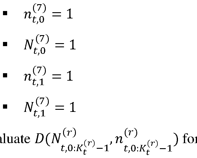
Figure imgf000027_0001
The actual value of ghd^,^ei can be obtained from the corresponding R-D curve, such as one of the example R-D curves described in the preceding section of this specification. The packet length is Q. Let us assume that there are R discrete bit rates (in terms of the number of packets as a unit) to consider,
Figure imgf000028_0001
We can group several consecutive packets together as one group and apply the same rateless code for each group. Given a budget bit rate M^l^, we have
Figure imgf000028_0002
groups, which is a design parameter. For each with index n ∈ ^0,1, … . , m^ ^ − 1^ at frame t, we can choose the number of source packets as
Figure imgf000028_0003
and the final total number of coded packets as M^l^ ^,^e . Note that, to enable the packets to be decodable, we need
Figure imgf000028_0004
. The total number of packets in the block set should not be than the target bandwidth M^l^ ^ in accordance with Eq. (15):Ue2 ^l^ ^l^ ^e 0 C/ M^,^e ≤ M^ (15) The assigned number of packets (M^l^ ,
Figure imgf000028_0005
) is based on the priority rule, namely, the group with smaller ID number has a higher priority than a group with a larger ID number. [00106] This problem can be represented by the packet successful decoding rate, wherein M^l^ ^,^e packets are sent and no less than 4^l^ ^,^e packets are received. Assume the packet loss rate is ^^, by being given the (M^l^ ^,^e , 4^l^ ^,^e ), the packet successful decoding probability for the (n′)th group at the channel coding level can be expressed as:
Figure imgf000028_0006
Note that there exists a decoding dependency -- the actual packet successful decoding probability for the (n′)th group at the source coding level is from all probabilities from earlier groups as follows:
Figure imgf000028_0007
where M^l^ represent the set collection of
Figure imgf000028_0008
represent the collection
Figure imgf000028_0009
[00107] Since
Figure imgf000028_0010
has a value smaller than 1, implicitly, the following constraint needs to be satisfied:
Figure imgf000028_0011
The overall quality of the received data can be expressed as: The optimization problem is to find both sets ^M^l^ ^,^e ^ and ^4^l^ ^,^e } to maximize the expected viewing experience. ^M^l^,Y^^ U^{^20 ^,^e ^, ^4Y^^ ^,^e^ = a ^r {gmax ∑ z ^eC/ ^^ ~kw^b,^l^ ^,^e ^M^l^ ^,/:^e , 4^l^ ^,/:^e ^ ∙ ghd^,^ei^ ^P ^ z,Qe ^,^3z,Qe ^ s.t. e ∑U ^eC 2 /0 M^l^ ^,^e ≤ M ^ ^l^ This problem differs from the NOW-problem formulation stated in the above-cited U.S. Provisional Application No.63/443,594 which is directed at determining the number of coded packets in each group since ^ is given. In the in the above-presented use case with bandwidth ^l^, we need determine both: (i) the number of source packets for each group
Figure imgf000029_0001
^l^ ^,^e and (ii) the number of packets for coded packets in each group 4^l^ ^,^e . Once the embedded bitstream is created, the quality measure is determined per packet, for each bit rate,
Figure imgf000029_0002
, and we can create the corresponding plan parameterized
Figure imgf000029_0003
[00108] Note that the above-formulated optimization problem is still an NP hard problem. Herein below, we provide a greedy algorithm to obtain an approximate solution to this problem by sequentially assigning one packet (either source or coded packet) at a time, until we reach the budget number M ^ ^l^. A qualitative description of the algorithm workflow is given in reference to FIG.24. [00109] FIG.24 is a block diagram illustrating an assignment procedure with a packet budget according to one example. In this example, the embedded bitstreams are packaged into packets of different respective priorities. The priority legend shown in FIG.24 indicates the relative priorities of the packets. The source packets are indicated in FIG.24 using the fill patterns shown in the priority legend. The blocks having a hash pattern indicate the corresponding rateless code (such as RLNC) coded packets. As an example, seven selection steps (S0-S6) are shown. At each of the steps (S0-S6), a respective next packet is selected and added by evaluating various selection options. The evaluated selection options are pictorially shown in the corresponding row to the right of the previous-step selection and are numbered as indicated in the “Evaluated Options” header. At the end of the outlined procedure, the assigned packets are directed to the rateless coding module (260), which processes them to produce the rateless embedded bitstream (298). [00110] Step (S0): Packet 0 is assigned because this packet is the highest priority source packet. m^^^ ^ = 1.
Figure imgf000030_0001
[00111] Step (S1): Packet 1 is being assigned. There are three options for this packet assignment. o Assign one source packet to group 0. m^^^ ^ = 1
Figure imgf000030_0002
o Assign one coded packet to group 0. m^^^ ^ = 1
Figure imgf000030_0003
o Assign one source packet to a new group 1. So, m^^^ ^ = 2 o each case and select the best one.
Figure imgf000030_0004
o For illustration purposes, we assume that option #2 is the best. [00112] Step (S2): Packet 2 is being assigned. There are three options for this packet assignment. o Assign one source packet to group 0. m^^^ ^ = 1 ^ ^ o Assign one coded packet to group 0. m^^^ ^ = 1
Figure imgf000031_0001
o Assign one source packet to a new group 1. So, m^^^ ^ = 2 ^ 4^^^ ^,/ = 1 ^ M^^^ ^,/ = 2 ^ 4^^^ ^,0 = 1 ^ M^^^ ^,0 = 1 o Evaluate ^^M^l^ ^,/:U^{^ z 20 , 4^l^ ^,/:U^{^ ^ for each option and select th z 20 e best one. o For illustration purposes, we assume that option #3 is the best. [00113] Step (S3): Packet 3 is being assigned. There are five options for this packet assignment. o Assign one source packet to group 0. m^^^ ^ = 2
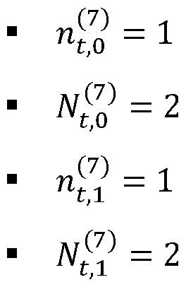
Figure imgf000031_0002
o Assign one coded packet to group 0. m^^^ ^ = 2
Figure imgf000031_0003
o Assign one source packet to group 1. m^^^ ^ = 2 ^ M^^^ ^,0 = 2 o Assign one coded packet to group 1. m^^^ ^ = 2
Figure imgf000032_0001
o Assign one source packet to a new group 2. So, m^^^ ^ = 3
Figure imgf000032_0002
o Evaluate ^^M^l^ ^,/:U^{^ z 20 , 4^l^ ^,/:U^{^ ^ for each option and select the best z 20 one. o For illustration purposes, we assume that option #4 is the best. [00114] Step (S4): Packet 4 is being assigned. There are five options for this packet assignment. o Assign one source packet to group 0. m^^^ ^ = 2
Figure imgf000032_0003
o Assign one coded packet to group 0. m^^^ ^ = 2 ^ ^ ^ ^ M^^^ ^,0 = 2 o Assign one source packet to group
Figure imgf000033_0001
= 2 ^ 4^^^ ^,/ = 1 ^ M^^^ ^,/ = 2 ^ 4^^^ ^,0 = 2 ^ M^^^ ^,0 = 3 o Assign one coded packet to group 1. m^^^ ^ = 2 ^ ^ ^ ^
Figure imgf000033_0002
o Assign one source packet to a new group 2. So, m^^^ ^ = 3 o each option and select the best one
Figure imgf000033_0003
o For illustration purposes, we assume that option #1 is the best. The evaluation process will continue in this manner until the packet budget is used up. In general, in each iteration, we need to evaluate 2m^l^ ^ + 1 possible assignments (options) and select the approximately best performing option. [00115] FIG.25 shows a pseudocode (2500) that can be used to implement the above-indicated assignment procedure according to one embodiment. Multiple-Description FEC (MD-FEC) based solution [00116] Some embodiments disclosed herein may benefit from the use of certain features disclosed in R. Puri, K.-W Lee, K. Ramchandran, and V. Bharghavan, “An integrated source transcoding and congestion control paradigm for video streaming in the Internet,” IEEE Transactions on Multimedia, 3(1):18-32, March 2001, which is incorporated herein by reference in its entirety. [00117] MD-FEC can beneficially be used to overcome or alleviate some of the joint source- channel progressive coding difficulties. As the name suggests, MD-FEC creates multiple descriptions, such that whenever we receive one more description, the reconstructed quality can be improved further. The descriptions are constructed via an FEC code, such as RLNC. The unit of description can be as small as one packet. With this design, the granularity of the reconstructed multimedia quality can be significantly improved while providing suitable amount of error protection for each quality level. [00118] FIGS.26A-26C are block diagrams illustrating application of MD-FEC coding to the embedded bitstream (242) according to one example. More specifically, FIG.26A illustrates the structure of the embedded bitstream (242) according to one example. FIG. 26B shows example distribution of various units of the embedded bitstream (242) of FIG. 26A over a packet set (2602). FIG. 26C shows a coded set (2604) produced by applying different rateless coding to different columns of the packet set (2602). [00119] Referring to FIG.26A, the embedded bitstream (242) shown therein is generated in the electronic decoder (200) as described above. One data unit of the embedded bitstream (242) packs q bytes of the source bitstream and is indicated by a square. The data units are in groups of different respective priorities. As an example, the embedded bitstream (242) is shown as including groups of data units of seven different priorities (P0-P6). The P0 priority group has the highest priority and includes a single data unit. The P1 priority group has the next highest priority and includes two data units. The P2 priority group has the next highest priority and includes three data units, and so on. The P6 priority group has the lowest priority and includes six data units. [00120] Referring to FIG.26B, the packet set (2602) has nine packets (PKT0-PKT8), each having a length of Q bytes. Each of the packets (PKT0-PKT8) has seven segments, each of the segments corresponding to the different respective one of the priorities (P0-P6). In the packet set, (2602), the packets (PKT0-PKT8) are arranged such that the segments corresponding to the same priority are aligned with each other, forming a column corresponding column. The single data unit of the P0 priority group is assigned, by the module (250), to the first column of the packet set (2602). The two data units of the P1 priority group are assigned, by the module (250), to the second column of the packet set (2602). The three data units of the P2 priority group are assigned, by the module (250), to the third column of the packet set (2602), and so on. The six data units of the P6 priority group are assigned, by the module (250), to the seventh column of the packet set (2602). [00121] Referring to FIG. 26C, to generate the coded set (2604) from the packet set (2602), the rateless coding module (260) applies a different respective rateless code of a plurality of rateless codes (NC0-NC6) on a column-by-column basis. For example, the first rateless code (NC0) is applied to the first column of the packet set (2602) to populate the first column of the coded set (2604). The first rateless code (NC0) is the strongest error-protection code among the rateless codes (NC0-NC6). The second rateless code (NC1) is applied to the second column of the packet set (2602) to populate the second column of the coded set (2604). The second rateless code (NC1) is the second strongest error-protection code among the rateless codes (NC0-NC6). The third rateless code (NC2) is applied to the third column of the packet set (2602) to populate the third column of the coded set (2604). The third rateless code (NC2) is the next strongest error-protection code among the rateless codes (NC0-NC6), and so on. The seventh rateless code (NC6) is applied to the seventh column of the packet set (2602) to populate the seventh column of the coded set (2604). The seventh rateless code (NC6) is the weakest error-protection code among the rateless codes (NC0-NC6). [00122] The rateless codes (NC0-NC6) are such that, for different priority levels, the original data units of the embedded bitstream (242) of FIG.26A are recoverable in the module (360) when at least a respective minimum number of packets from the coded set (2604) is received by the electronic decoder (300). In the example shown, the rateless code (NC0) is such that the data unit of the P0 priority group can be recovered when any one of the packets (PKT0-PKT8) of the coded set (2604) is received by the electronic decoder (300). The rateless code (NC1) is such that the two data units of the P1 priority group can be recovered when any two of the packets (PKT0-PKT8) of the coded set (2604) are received by the electronic decoder (300). The rateless codes (NC2, NC3) are such that the three data units of the P2 priority group and the three data units of the P3 priority group can be recovered when any three of the packets (PKT0-PKT8) of the coded set (2604) are received by the electronic decoder (300), and so on. The rateless code (NC6) is such that the six data units of the P6 priority group can be recovered when any six of the packets (PKT0-PKT8) of the coded set (2604) are received by the electronic decoder (300). [00123] With the above MD-FEC design, we can fully utilize the properties of embedded bitstream. For example, we can consider only the highest bit rate (M^k20^ ^ ), without generating the transmission plans for all different available bit rates. The following description generalizes this MD-FEC based approach and provides a recipe of how to assign the number of data units, 4^,^, in each column k’ of the packet set that has a structure similar to that of the packet set (2602). Without loss of generality, we assume each data unit is one byte. Under this assumption, we will have Q/1=Q columns in the packet set. [00124] Let us assume that the packet loss rate is ^ . For a ^k20^ ^ given coding configuration, (M^ , 4 ), the successful d th ^,^e ecoding probability for the (n′) column of a packet can be expressed as:
Figure imgf000036_0001
To enforce the priority (a stronger error protection level for a higher priority of the data unit), we employ the following constraint:
Figure imgf000036_0002
Since we have the same number of coded packets, M^k20^ ^ , the above constraint can be presented as a constraint on the number of source units, 4^,^e:
Figure imgf000036_0003
[00125] Let us denote the increased quality using the number of data units, 4^,^o, in column k’ as
Figure imgf000036_0004
Note that this quality measurement has a dependency on the number of data units in the previous column 0 to k’−1. The expected received quality can be expressed as:
Figure imgf000036_0005
We can now formulate the assignment task as the following optimization problem: ^4Y^^ ^,^e^ = argmax ∑F20 ^eC/ ^^^ R^^M^k20^ ^ , 4^,^e^ ∙ gh^^,^ei^ ^3z,Qe ^ s.t. 4^,^e20 ≤ 4^,^e ≤ 4^,^e^0 [00126] FIGS.27A-27H are block diagrams illustrating a sequence of operations of an algorithm that can be used to implement an assignment task for the MD-FEC based solution according to one example. The algorithm provides an approximate iterative solution to the above optimization problem and is illustrated in FIGS.27A-27H by showing operations directed at sequentially determining the assignment in each row of the packet set (2602), also see FIG.26B. [00127] FIG. 27A illustrates an initial step of the algorithm, wherein, for the first row (PKT0) of the packet set (2602), the algorithm assigns one data unit (shown in black) for each of the columns. After this initial assignment, the algorithm evaluates seven options for the second row, as illustrated in FIGS.27B-27E. The first option shown in FIG. 27B is to assign one data unit for each of the columns of the second row (PKT1) by repeating the same assignment as that used for the first row. The first option shown in FIG. 27C is similar to repeating the first-row assignment but without assigning the data unit for the first column. The third option shown in FIG.27D is not to assign the first two data units at the second row (PKT1). The other four options include gradually reducing, by one data unit at a time, the second-row assignment until the last column is reached. FIG. 27E shows the last option for the second row (PKT1). Among the seven options illustrated by FIGS.27B-27E, the algorithm computes the expected quality and selects the best option. For illustration purposes, let us assume that the second option (FIG.27C) has the best quality. The algorithm then proceeds to continue the unit assignment for the third row (PKT2). [00128] At the third row (PKT2), the algorithm repeats the above procedure, but now evaluates six options. The first of the six options is illustrated in FIG.27F, wherein the unit assignment used in the second row (PKT1) is repeated in the third row (PKT2). The second of the six options is similar to repeating the second row in the third row, but now without the first data unit thereof, as indicated in FIG.27G. The evaluation process proceeds by removing more and more data units. The last of the six options is illustrated in FIG. 27H. Among the six options illustrated by FIGS. 27F-27H, the algorithm computes the expected quality and selects the best option. The algorithm then proceeds to continue the unit assignment for the fourth row (PKT3), and so on. The algorithm continues to advance in the above-described manner until we do not have any more rows (packets) or any more columns (data units) to process. [00129] FIG. 28 shows a pseudocode (2800) representing a greedy algorithm that can be used to implement the above-indicated assignment procedure according to one embodiment. After the module (250) of the encoder (200) determines the set ^ 4^,^e^ via the algorithm (2800), the module (260) operates apply different respective rateless codes to each column of the packet set (2602) to generate coded packets. Note that for each column, the module (360) of the decoder (300) will need the different respective sets of rateless code coefficients to perform rateless decoding. In some embodiments, to avoid the overhead of transmitting the sets of rateless code coefficients from the encoder (200) to the decoder (300), the same pseudo random number generator is used at both the encoder (200) and decoder (300), and the transmission of the sets of rateless code coefficients is substituted by the transmission of the corresponding random number seed(s), which are relatively small and incur little overhead. Example Hardware [00130] FIG. 29 is a block diagram illustrating a computing device (2900) according to an embodiment. The device (2900) can be used, e.g., to implement the encoder (200) or the decoder (300). The computing device (2900) comprises input/output (I/O) devices (2910), a processing engine (2920), and a memory (2930). The I/O devices (2910) may be used to enable the device (2900) to receive various input signals (2902) and to output various output signals (2904). For example, when the computing device (2900) implements the encoder (200), the input signals (2902) include the neural field (202), whereas the output signals (2904) include the bitstream (298) and corresponding metadata (when applicable). When the computing device (2900) implements the decoder (300), the input signals (2902) include the received bitstream (298′) and corresponding metadata (if any), whereas the output signals (2904) include the reconstructed neural field (312). [00131] The memory (2930) may have buffers to receive neural field data and/or other pertinent data. Once the data are received, the memory (2930) may provide parts of the data to the processing engine (2920) for processing therein. The processing engine (2920) includes a processor (2922) and a memory (2924). The memory (2924) may store therein program code, which when executed by the processor (2922) enables the processing engine (2920) to perform data processing, including but not limited to the above-described encoding and/or decoding methods. [00132] According to an example embodiment disclosed above, e.g., in the summary section and/or in reference to any one or any combination of some or all of FIGS. 1-29, provided is an apparatus for neural-network streaming, the apparatus comprising: at least one processor; and at least one memory including program code; and wherein the at least one memory and the program code are configured to, with the at least one processor, cause the apparatus at least to: apply progressive coding to a plurality of coefficients representing a first neural field to determine a priority order of coding units in a first bitstream including a base layer and a progressively decodable enhancement layer; generate a second bitstream by applying entropy coding to the coding units of the first bitstream, the second bitstream being an embedded bitstream having a plurality of data units thereof arranged in the priority order; assign subsets of the plurality of data units to packets of a packet set based on the priority order; and generate an output stream of coded packets by applying rateless coding to the packet set, the output stream being a rateless embedded bitstream. [00133] According to another example embodiment disclosed above, e.g., in the summary section and/or in reference to any one or any combination of some or all of FIGS. 1-29, provided is method of neural-network streaming comprising: applying progressive coding to a plurality of coefficients representing a first neural field to determine a priority order of coding units in a first bitstream including a base layer and a progressively decodable enhancement layer; generating a second bitstream by applying entropy coding to the coding units of the first bitstream, the second bitstream being an embedded bitstream having a plurality of data units thereof arranged in the priority order; assigning subsets of the plurality of data units to packets of a packet set based on the priority order; and generating an output stream of coded packets by applying rateless coding to the packet set, the output stream being a rateless embedded bitstream. [00134] In some embodiments of the above method, the method further comprises: applying neural-network model reduction to a second neural field to generate the first neural field; and applying neural-network coefficient quantization to generate the plurality of coefficients representing the first neural field. [00135] In some embodiments of any of the above methods, the base layer includes one or more bit planes of most-significant bits of the plurality of coefficients. [00136] In some embodiments of any of the above methods, the method further comprises populating portions of the progressively decodable enhancement layer by scanning, in the plurality of coefficients, a plurality of bit planes not included in the base layer. [00137] In some embodiments of any of the above methods, the scanning of a bit plane of the plurality of bit planes is performed across multiple sets of coefficients, each of the sets corresponding to a different respective layer of a neural network encoding the first neural field. [00138] In some embodiments of any of the above methods, the scanning of the plurality of bit planes includes scanning bit planes of a next set of coefficients after completing a scan of bit planes of a preceding set of coefficients, the next set of coefficients and the preceding set of coefficients corresponding to different respective layers of a neural network encoding the first neural field. [00139] In some embodiments of any of the above methods, each layer of a neural network encoding the first neural field is represented by a respective set of coefficients; wherein each respective set of coefficients includes a respective plurality of blocks of bits; and wherein the scanning of the plurality of bit planes includes scanning bit planes of a next block of bits after completing a scan of bit planes of a preceding block of bits. [00140] In some embodiments of any of the above methods, the next block of bits and the preceding block of bits are in different respective sets of coefficients. [00141] In some embodiments of any of the above methods, the next block of bits and the preceding block of bits are in a same set of coefficients. [00142] In some embodiments of any of the above methods, an order in which the blocks of bits are scanned is determined based on evaluation of quality-metric changes corresponding to different selections of the next block of bits. Representative examples of suitable quality metrics include, but are not limited to, PSNR, Structural Similarity Index Measure (SSIM), and Learned Perceptual Image Patch Similarity (LPIPS). [00143] In some embodiments of any of the above methods, an order in which the blocks of coefficients are scanned is determined based on evaluation of quality-metric changes corresponding to different selections of the next block of bits and further based on evaluation of quality-metric changes corresponding to one or more subsequent block selections for each of the different selections of the next block of bits. [00144] In some embodiments of any of the above methods, the applying rateless coding includes: applying a first rateless code to a first subset of the plurality of data units; and applying a second rateless code to a second subset of the plurality of data units, the first rateless code being a stronger error-correction code than the second rateless code. [00145] In some embodiments of any of the above methods, the applying the rateless coding further includes applying a third rateless code to a third subset of the plurality of data units, the second rateless code being a stronger error-correction code than the third rateless code. [00146] In some embodiments of any of the above methods, the applying the rateless coding includes applying multiple-description forward-error-correction coding to the packet set. [00147] In some embodiments of any of the above methods, the assigning is based on iterative packet-by-packet evaluation of quality-metric changes corresponding to one or more subsequent data-unit selections for a next packet of the packet set. [00148] In some embodiments of any of the above methods, the method further comprises transmitting metadata with the output stream of coded packets, the metadata specifying one or more parameters of the progressive coding and the rateless coding. [00149] In some embodiments of any of the above methods, the generating said output stream of coded packets comprises evaluating a quality metric for a respective plurality of options available at each iteration of an iterative evaluation process, the options being selected from the group consisting of: assigning one source packet to an existing group of packets; assigning one coded packet to an existing group of packets; assigning one source packet to a new group of packets; and assigning one coded packet to a new group of packets. [00150] In some embodiments of any of the above methods, the generating said output stream of coded packets further comprises, at each iteration, selecting among the respective plurality of options an option characterized by a respective most favorable value of the quality metric. [00151] In some embodiments of any of the above methods, the respective plurality of options is constrained by at least one of: a budget bit rate; a number of source packets in a block; a total number of packets in a block, the total number being a sum of a corresponding number of source packets and a corresponding number of coded packets; and a priority constraint. [00152] In some embodiments of any of the above methods, the generating said output stream of coded packets comprises using a forward-error-correction code to create a plurality of descriptions representing the first neural field, each of the descriptions being characterized by a different respective value of a quality metric. [00153] In some embodiments of any of the above methods, each of the plurality of descriptions is error-protected by a different respective rateless code of the forward-error-correction code. [00154] In some embodiments of any of the above methods, the method further comprises: iteratively evaluating the quality metric to select source data units for being error-protected by the different respective rateless codes of the forward-error-correction code; and selecting the source data units to obtain a most favorable set of values of the quality metric for the different respective rateless codes of the forward-error-correction code. [00155] In some embodiments of any of the above methods, the method further comprises: partitioning binary values of the plurality of coefficients into blocks of bits; indexing the blocks of bits; evaluating a quality metric for each of the blocks of bits; sorting the blocks of bits in an order from a most favorable value of the evaluated quality metric to a least favorable value of the evaluated quality metric; and selecting, from the sorted blocks of bits, two or more candidate blocks for further evaluation based on the order and further based on the indexing. [00156] In some embodiments of any of the above methods, the method further comprises performing said further evaluation of each of the two or more candidate blocks by performing one or more additional selection iterations among remaining ones of the blocks of bits and evaluating the quality metric for the one or more additional selection iterations. [00157] According to yet another example embodiment disclosed above, e.g., in the summary section and/or in reference to any one or any combination of some or all of FIGS.1-29, provided is an apparatus for reconstructing a neural field, the apparatus comprising: at least one processor; and at least one memory including program code; and wherein the at least one memory and the program code are configured to, with the at least one processor, cause the apparatus at least to: receive an input stream of coded packets having encoded therein a first plurality of coefficients representing the neural field, the input stream being a rateless embedded bitstream; apply rateless decoding to a partial packet set received via the input bitstream to recover a corresponding subset of a plurality of source data units encoded in the coded packets; apply entropy decoding to the corresponding subset of the plurality of source data units to approximately reconstruct corresponding uncompressed source data; and apply progressive decoding to the corresponding uncompressed source data to approximately reconstruct the first plurality of coefficients. [00158] According to yet another example embodiment disclosed above, e.g., in the summary section and/or in reference to any one or any combination of some or all of FIGS.1-29, provided is a method of reconstructing a neural field comprising: receiving an input stream of coded packets having encoded therein a first plurality of coefficients representing the neural field, the input stream being a rateless embedded bitstream; applying rateless decoding to a partial packet set received via the input bitstream to recover a corresponding subset of a plurality of source data units encoded in the coded packets; applying entropy decoding to the corresponding subset of the plurality of source data units to approximately reconstruct corresponding uncompressed source data; and applying progressive decoding to the corresponding uncompressed source data to approximately reconstruct the first plurality of coefficients. [00159] In some embodiments of the above method, the method further comprises applying inverse quantization to the approximately reconstructed first plurality of coefficients to approximately reconstruct an original plurality of coefficients representing the neural field. [00160] In some embodiments of any of the above methods, the progressive decoding is performed based on metadata specifying an order in which a plurality of bit planes of the first plurality of coefficients has been scanned at a corresponding electronic decoder for a progressively decodable enhancement layer of an embedded bitstream carried via the coded packets. [00161] In some embodiments of any of the above methods, the metadata specify one scanning option selected from the group consisting of: a first scanning option, wherein scanning of a bit plane of the plurality of bit planes is performed across multiple sets of coefficients, each of the sets corresponding to a different respective layer of a neural network encoding the neural field; a second scanning option, wherein scanning of the plurality of bit planes includes scanning bit planes of a next set of coefficients after completing a scan of bit planes of a preceding set of coefficients, the next set of coefficients and the preceding set of coefficients corresponding to different respective layers of a neural network encoding the first neural field; and a third option, wherein: each layer of the neural network is represented by a respective set of coefficients; each respective set of coefficients includes a respective plurality of blocks of bits; and scanning of the plurality of bit planes includes scanning bit planes of a next block of bits after completing a scan of bit planes of a preceding block of bits. [00162] In some embodiments of any of the above methods, the rateless decoding is performed based on metadata specifying one or more parameters of corresponding rateless encoding performed at a corresponding electronic decoder. [00163] In some embodiments of any of the above methods, the applying rateless decoding includes: applying a first rateless code to a first subset of data units of the partial packet set; and applying a second rateless code to a second subset of data units of the partial packet set, the first rateless code being a stronger error-correction code than the second rateless code. [00164] In some embodiments of any of the above methods, parameters of the first rateless code and the second rateless code are specified via metadata received with the input stream of coded packets. [00165] In some embodiments of any of the above methods, the parameters include a first random seed corresponding to the first rateless code and a second random seed corresponding to the second rateless code. [00166] In some embodiments of any of the above methods, the applying the rateless decoding includes applying multiple-description forward-error-correction decoding to the partial packet set. [00167] With regard to the processes, systems, methods, heuristics, etc. described herein, it should be understood that, although the steps of such processes, etc. have been described as occurring according to a certain ordered sequence, such processes could be practiced with the described steps performed in an order other than the order described herein. It further should be understood that certain steps could be performed simultaneously, that other steps could be added, or that certain steps described herein could be omitted. In other words, the descriptions of processes herein are provided for the purpose of illustrating certain embodiments and should in no way be construed so as to limit the claims. [00168] Accordingly, it is to be understood that the above description is intended to be illustrative and not restrictive. Many embodiments and applications other than the examples provided would be apparent upon reading the above description. The scope should be determined, not with reference to the above description, but should instead be determined with reference to the appended claims, along with the full scope of equivalents to which such claims are entitled. It is anticipated and intended that future developments will occur in the technologies discussed herein, and that the disclosed systems and methods will be incorporated into such future embodiments. In sum, it should be understood that the application is capable of modification and variation. [00169] All terms used in the claims are intended to be given their broadest reasonable constructions and their ordinary meanings as understood by those knowledgeable in the technologies described herein unless an explicit indication to the contrary is made herein. In particular, use of the singular articles such as “a,” “the,” “said,” etc. should be read to recite one or more of the indicated elements unless a claim recites an explicit limitation to the contrary. [00170] The Abstract of the Disclosure is provided to allow the reader to quickly ascertain the nature of the technical disclosure. It is submitted with the understanding that it will not be used to interpret or limit the scope or meaning of the claims. In addition, in the foregoing Detailed Description, it can be seen that various features are grouped together in various embodiments for the purpose of streamlining the disclosure. This method of disclosure is not to be interpreted as reflecting an intention that the claimed embodiments incorporate more features than are expressly recited in each claim. Rather, as the following claims reflect, inventive subject matter lies in fewer than all features of a single disclosed embodiment. Thus, the following claims are hereby incorporated into the Detailed Description, with each claim standing on its own as a separately claimed subject matter. [00171] While this disclosure includes references to illustrative embodiments, this specification is not intended to be construed in a limiting sense. Various modifications of the described embodiments, as well as other embodiments within the scope of the disclosure, which are apparent to persons skilled in the art to which the disclosure pertains are deemed to lie within the principle and scope of the disclosure, e.g., as expressed in the following claims. [00172] Some embodiments may be implemented as circuit-based processes, including possible implementation on a single integrated circuit. [00173] Some embodiments can be embodied in the form of methods and apparatuses for practicing those methods. Some embodiments can also be embodied in the form of program code recorded in tangible media, such as magnetic recording media, optical recording media, solid state memory, floppy diskettes, CD-ROMs, hard drives, or any other non-transitory machine-readable storage medium, wherein, when the program code is loaded into and executed by a machine, such as a computer, the machine becomes an apparatus for practicing the patented invention(s). Some embodiments can also be embodied in the form of program code, for example, stored in a non- transitory machine-readable storage medium including being loaded into and/or executed by a machine, wherein, when the program code is loaded into and executed by a machine, such as a computer or a processor, the machine becomes an apparatus for practicing the patented invention(s). When implemented on a general-purpose processor, the program code segments combine with the processor to provide a unique device that operates analogously to specific logic circuits. [00174] Unless explicitly stated otherwise, each numerical value and range should be interpreted as being approximate as if the word “about” or “approximately” preceded the value or range. [00175] The use of figure numbers and/or figure reference labels in the claims is intended to identify one or more possible embodiments of the claimed subject matter in order to facilitate the interpretation of the claims. Such use is not to be construed as necessarily limiting the scope of those claims to the embodiments shown in the corresponding figures. [00176] Although the elements in the following method claims, if any, are recited in a particular sequence with corresponding labeling, unless the claim recitations otherwise imply a particular sequence for implementing some or all of those elements, those elements are not necessarily intended to be limited to being implemented in that particular sequence. [00177] Reference herein to “one embodiment” or “an embodiment” means that a particular feature, structure, or characteristic described in connection with the embodiment can be included in at least one embodiment of the disclosure. The appearances of the phrase “in one embodiment” in various places in the specification are not necessarily all referring to the same embodiment, nor are separate or alternative embodiments necessarily mutually exclusive of other embodiments. The same applies to the term “implementation.” [00178] Unless otherwise specified herein, the use of the ordinal adjectives “first,” “second,” “third,” etc., to refer to an object of a plurality of like objects merely indicates that different instances of such like objects are being referred to, and is not intended to imply that the like objects so referred-to have to be in a corresponding order or sequence, either temporally, spatially, in ranking, or in any other manner. [00179] Unless otherwise specified herein, in addition to its plain meaning, the conjunction “if” may also or alternatively be construed to mean “when” or “upon” or “in response to determining” or “in response to detecting,” which construal may depend on the corresponding specific context. For example, the phrase “if it is determined” or “if [a stated condition] is detected” may be construed to mean “upon determining” or “in response to determining” or “upon detecting [the stated condition or event]” or “in response to detecting [the stated condition or event].” [00180] Also for purposes of this description, the terms “couple,” “coupling,” “coupled,” “connect,” “connecting,” or “connected” refer to any manner known in the art or later developed in which energy is allowed to be transferred between two or more elements, and the interposition of one or more additional elements is contemplated, although not required. Conversely, the terms “directly coupled,” “directly connected,” etc., imply the absence of such additional elements. [00181] As used herein in reference to an element and a standard, the term compatible means that the element communicates with other elements in a manner wholly or partially specified by the standard and would be recognized by other elements as sufficiently capable of communicating with the other elements in the manner specified by the standard. The compatible element does not need to operate internally in a manner specified by the standard. [00182] The functions of the various elements shown in the figures, including any functional blocks labeled as “processors” and/or “controllers,” may be provided through the use of dedicated hardware as well as hardware capable of executing software in association with appropriate software. When provided by a processor, the functions may be provided by a single dedicated processor, by a single shared processor, or by a plurality of individual processors, some of which may be shared. Moreover, explicit use of the term “processor” or “controller” should not be construed to refer exclusively to hardware capable of executing software, and may implicitly include, without limitation, digital signal processor (DSP) hardware, network processor, application specific integrated circuit (ASIC), field programmable gate array (FPGA), read only memory (ROM) for storing software, random access memory (RAM), and nonvolatile storage. Other hardware, conventional and/or custom, may also be included. Similarly, any switches shown in the figures are conceptual only. Their function may be carried out through the operation of program logic, through dedicated logic, through the interaction of program control and dedicated logic, or even manually, the particular technique being selectable by the implementer as more specifically understood from the context. [00183] As used in this application, the terms “circuit,” “circuitry” may refer to one or more or all of the following: (a) hardware-only circuit implementations (such as implementations in only analog and/or digital circuitry); (b) combinations of hardware circuits and software, such as (as applicable): (i) a combination of analog and/or digital hardware circuit(s) with software/firmware and (ii) any portions of hardware processor(s) with software (including digital signal processor(s)), software, and memory(ies) that work together to cause an apparatus, such as a mobile phone or server, to perform various functions); and (c) hardware circuit(s) and or processor(s), such as a microprocessor(s) or a portion of a microprocessor(s), that requires software (e.g., firmware) for operation, but the software may not be present when it is not needed for operation.” This definition of circuitry applies to all uses of this term in this application, including in any claims. As a further example, as used in this application, the term circuitry also covers an implementation of merely a hardware circuit or processor (or multiple processors) or portion of a hardware circuit or processor and its (or their) accompanying software and/or firmware. The term circuitry also covers, for example and if applicable to the particular claim element, a baseband integrated circuit or processor integrated circuit for a mobile device or a similar integrated circuit in server, a cellular network device, or other computing or network device. [00184] It should be appreciated by those of ordinary skill in the art that any block diagrams herein represent conceptual views of illustrative circuitry embodying the principles of the disclosure. Similarly, it will be appreciated that any flow charts, flow diagrams, state transition diagrams, pseudo code, and the like represent various processes which may be substantially represented in computer readable medium and so executed by a computer or processor, whether or not such computer or processor is explicitly shown. [00185] “BRIEF SUMMARY OF SOME SPECIFIC EMBODIMENTS” in this specification is intended to introduce some example embodiments, with additional embodiments being described in “DETAILED DESCRIPTION” and/or in reference to one or more drawings. “BRIEF SUMMARY OF SOME SPECIFIC EMBODIMENTS” is not intended to identify essential elements or features of the claimed subject matter, nor is it intended to limit the scope of the claimed subject matter.

Claims

CLAIMS What is claimed is: 1. A method of neural-network streaming, comprising: applying progressive coding to a plurality of coefficients representing a first neural field to determine a priority order of coding units in a first bitstream including a base layer and a progressively decodable enhancement layer; generating a second bitstream by applying entropy coding to the coding units of the first bitstream, the second bitstream being an embedded bitstream having a plurality of data units thereof arranged in the priority order; assigning subsets of the plurality of data units to packets of a packet set based on the priority order; and generating an output stream of coded packets by applying rateless coding to the packet set, the output stream being a rateless embedded bitstream.
2. The method of claim 1, further comprising: applying neural-network model reduction to a second neural field to generate the first neural field; and applying neural-network coefficient quantization to generate the plurality of coefficients representing the first neural field.
3. The method of claim 1 or 2, wherein the base layer includes one or more bit planes of most- significant bits of the plurality of coefficients.
4. The method of claim 3, further comprising populating portions of the progressively decodable enhancement layer by scanning, in the plurality of coefficients, a plurality of bit planes not included in the base layer.
5. The method of claim 4, wherein the scanning of a bit plane of the plurality of bit planes is performed across multiple sets of coefficients, each of the sets corresponding to a different respective layer of a neural network encoding the first neural field.
6. The method of claim 4, wherein the scanning of the plurality of bit planes includes scanning bit planes of a next set of coefficients after completing a scan of bit planes of a preceding set of coefficients, the next set of coefficients and the preceding set of coefficients corresponding to different respective layers of a neural network encoding the first neural field.
7. The method of claim 4, wherein each layer of a neural network encoding the first neural field is represented by a respective set of coefficients; wherein each respective set of coefficients includes a respective plurality of blocks of bits; and wherein the scanning of the plurality of bit planes includes scanning bit planes of a next block of bits after completing a scan of bit planes of a preceding block of bits.
8. The method of claim 7, wherein the next block of bits and the preceding block of bits are in different respective sets of coefficients.
9. The method of claim 7, wherein the next block of bits and the preceding block of bits are in a same set of coefficients.
10. The method of claim 7, wherein an order in which the blocks of bits are scanned is determined based on evaluation of quality-metric changes corresponding to different selections of the next block of bits.
11. The method of claim 7, wherein an order in which the blocks of coefficients are scanned is determined based on evaluation of quality-metric changes corresponding to different selections of the next block of bits and further based on evaluation of quality-metric changes corresponding to one or more subsequent block selections for each of the different selections of the next block of bits.
12. The method of any preceding claim, wherein the applying rateless coding includes: applying a first rateless code to a first subset of the plurality of data units; applying a second rateless code to a second subset of the plurality of data units, the first rateless code being a stronger error-correction code than the second rateless code.
13. The method of claim 12, wherein the applying the rateless coding further includes applying a third rateless code to a third subset of the plurality of data units, the second rateless code being a stronger error-correction code than the third rateless code.
14. The method of any preceding claim, wherein the applying the rateless coding includes applying multiple-description forward-error-correction coding to the packet set.
15. The method of any preceding claim, wherein the assigning is based on iterative packet-by- packet evaluation of quality metric changes corresponding to one or more subsequent data-unit selections for a next packet of the packet set.
16. The method of any preceding claim, further comprising transmitting metadata with the output stream of coded packets, the metadata specifying one or more parameters of the progressive coding and the rateless coding.
17. The method of any preceding claim, wherein the generating said output stream of coded packets comprises evaluating a quality metric for a respective plurality of options available at each iteration of an iterative evaluation process, the options being selected from the group consisting of: assigning one source packet to an existing group of packets; assigning one coded packet to an existing group of packets; assigning one source packet to a new group of packets; and assigning one coded packet to a new group of packets.
18. The method of claim 17, wherein the generating said output stream of coded packets further comprises, at each iteration, selecting among the respective plurality of options an option characterized by a respective most favorable value of the quality metric.
19. The method of claim 17 or 18, wherein the respective plurality of options is constrained by at least one of: a budget bit rate; a number of source packets in a block; a total number of packets in a block, the total number being a sum of a corresponding number of source packets and a corresponding number of coded packets; and a priority constraint.
20. The method of any preceding claim, wherein the generating said output stream of coded packets comprises using a forward-error-correction code to create a plurality of descriptions representing the first neural field, each of the descriptions being characterized by a different respective value of a quality metric.
21. The method of claim 20, wherein each of the plurality of descriptions is error-protected by a different respective rateless code of the forward-error-correction code.
22. The method of claim 21, further comprising: iteratively evaluating the quality metric to select source data units for being error-protected by the different respective rateless codes of the forward-error-correction code; and selecting the source data units to obtain a most favorable set of values of the quality metric for the different respective rateless codes of the forward-error-correction code.
23. The method of any preceding claim, further comprising: partitioning binary values of the plurality of coefficients into blocks of bits; indexing the blocks of bits; evaluating a quality metric for each of the blocks of bits; sorting the blocks of bits in an order from a most favorable value of the evaluated quality metric to a least favorable value of the evaluated quality metric; and selecting, from the sorted blocks of bits, two or more candidate blocks for further evaluation based on the order and further based on the indexing.
24. The method of claim 23, further comprising performing said further evaluation of each of the two or more candidate blocks by performing one or more additional selection iterations among remaining ones of the blocks of bits and evaluating the quality metric for the one or more additional selection iterations.
25. A method of reconstructing a neural field, comprising: receiving an input stream of coded packets having encoded therein a first plurality of coefficients representing the neural field, the input stream being a rateless embedded bitstream; applying rateless decoding to a partial packet set received via the input bitstream to recover a corresponding subset of a plurality of source data units encoded in the coded packets; applying entropy decoding to the corresponding subset of the plurality of source data units to approximately reconstruct corresponding uncompressed source data; and applying progressive decoding to the corresponding uncompressed source data to approximately reconstruct the first plurality of coefficients.
26. The method of claim 25, further comprising applying inverse quantization to the approximately reconstructed first plurality of coefficients to approximately reconstruct an original plurality of coefficients representing the neural field.
27. The method of claim 25 or 26, wherein the progressive decoding is performed based on metadata specifying an order in which a plurality of bit planes of the first plurality of coefficients has been scanned at a corresponding electronic decoder for a progressively decodable enhancement layer of an embedded bitstream carried via the coded packets.
28. The method of any one of claims 25 to 27, wherein the metadata specify one scanning option selected from the group consisting of: a first scanning option, wherein scanning of a bit plane of the plurality of bit planes is performed across multiple sets of coefficients, each of the sets corresponding to a different respective layer of a neural network encoding the neural field; a second scanning option, wherein scanning of the plurality of bit planes includes scanning bit planes of a next set of coefficients after completing a scan of bit planes of a preceding set of coefficients, the next set of coefficients and the preceding set of coefficients corresponding to different respective layers of a neural network encoding the first neural field; and a third option, wherein: each layer of the neural network is represented by a respective set of coefficients; each respective set of coefficients includes a respective plurality of blocks of bits; and scanning of the plurality of bit planes includes scanning bit planes of a next block of bits after completing a scan of bit planes of a preceding block of bits.
29. The method of any one of claims 25 to 28, wherein the rateless decoding is performed based on metadata specifying one or more parameters of corresponding rateless encoding performed at a corresponding electronic decoder.
30. The method of any one of claims 25 to 29, wherein the applying rateless decoding includes: applying a first rateless code to a first subset of data units of the partial packet set; and applying a second rateless code to a second subset of data units of the partial packet set, the first rateless code being a stronger error-correction code than the second rateless code.
31. The method of claim 30, wherein parameters of the first rateless code and the second rateless code are specified via metadata received with the input stream of coded packets.
32. The method of claim 31, wherein the parameters include a first random seed corresponding to the first rateless code and a second random seed corresponding to the second rateless code.
33. The method of any one of claims 25 to 32, wherein the applying the rateless decoding includes applying multiple-description forward-error-correction decoding to the partial packet set.
34. An apparatus for neural-network streaming, the apparatus comprising: at least one processor; and at least one memory including program code; and wherein the at least one memory and the program code are configured to, with the at least one processor, cause the apparatus to perform the method of any one of claims 1 to 33.
35. A non-transitory computer-readable medium storing instructions that, when executed by an electronic processor, cause the electronic processor to perform operations comprising a method of any one of claims 1 to 33.
PCT/US2024/032835 2023-06-14 2024-06-06 Error protection for neural field streaming Ceased WO2024258731A1 (en)

Priority Applications (1)

Application Number Priority Date Filing Date Title
EP24737844.1A EP4728734A1 (en) 2023-06-14 2024-06-06 Error protection for neural field streaming

Applications Claiming Priority (4)

Application Number Priority Date Filing Date Title
US202363508114P 2023-06-14 2023-06-14
US63/508,114 2023-06-14
EP23183755 2023-07-06
EP23183755.0 2023-07-06

Publications (1)

Publication Number Publication Date
WO2024258731A1 true WO2024258731A1 (en) 2024-12-19

Family

ID=91759550

Family Applications (1)

Application Number Title Priority Date Filing Date
PCT/US2024/032835 Ceased WO2024258731A1 (en) 2023-06-14 2024-06-06 Error protection for neural field streaming

Country Status (2)

Country Link
EP (1) EP4728734A1 (en)
WO (1) WO2024258731A1 (en)

Citations (3)

* Cited by examiner, † Cited by third party
Publication number Priority date Publication date Assignee Title
US20090232408A1 (en) * 2008-03-12 2009-09-17 The Boeing Company Error-Resilient Entropy Coding For Partial Embedding And Fine Grain Scalability
US20180173994A1 (en) * 2016-12-15 2018-06-21 WaveOne Inc. Enhanced coding efficiency with progressive representation
WO2022159897A1 (en) * 2021-01-25 2022-07-28 Qualcomm Incorporated Progressive data compression using artificial neural networks

Patent Citations (3)

* Cited by examiner, † Cited by third party
Publication number Priority date Publication date Assignee Title
US20090232408A1 (en) * 2008-03-12 2009-09-17 The Boeing Company Error-Resilient Entropy Coding For Partial Embedding And Fine Grain Scalability
US20180173994A1 (en) * 2016-12-15 2018-06-21 WaveOne Inc. Enhanced coding efficiency with progressive representation
WO2022159897A1 (en) * 2021-01-25 2022-07-28 Qualcomm Incorporated Progressive data compression using artificial neural networks

Non-Patent Citations (4)

* Cited by examiner, † Cited by third party
Title
CHAU PHUC ET AL: "Hierarchical random linear network coding for multicast scalable video streaming", SIGNAL AND INFORMATION PROCESSING ASSOCIATION ANNUAL SUMMIT AND CONFERENCE (APSIPA), 2014 ASIA-PACIFIC, ASIA-PACIFIC SIGNAL AND INFORMATION PROCESSING ASS, 9 December 2014 (2014-12-09), pages 1 - 7, XP032736581, DOI: 10.1109/APSIPA.2014.7041711 *
HEINER KIRCHHOFFERPAUL HAASEWOJCIECH SAMEK ET AL.: "Overview of the Neural Network Compression and Representation (NNR) Standard", IEEE TRANSACTIONS ON CIRCUITS AND SYSTEMS FOR VIDEO TECHNOLOGY, vol. 32, no. 5, 2022, pages 3203 - 3216
R. PURIK.-W LEEK. RAMCHANDRANV. BHARGHAVAN: "An integrated source transcoding and congestion control paradigm for video streaming in the Internet", IEEE TRANSACTIONS ON MULTIMEDIA, vol. 3, no. 1, March 2001 (2001-03-01), pages 18 - 32, XP011036233
THOMOS NIKOLAOS ET AL: "Adaptive Prioritized Random Linear Coding and Scheduling for Layered Data Delivery From Multiple Servers", IEEE TRANSACTIONS ON MULTIMEDIA, IEEE, USA, vol. 17, no. 6, 1 June 2015 (2015-06-01), pages 893 - 906, XP011581071, ISSN: 1520-9210, [retrieved on 20150513], DOI: 10.1109/TMM.2015.2425228 *

Also Published As

Publication number Publication date
EP4728734A1 (en) 2026-04-22

Similar Documents

Publication Publication Date Title
Williams et al. Hierarchical quantized autoencoders
US20230106778A1 (en) Quantization for Neural Networks
US11532104B2 (en) Method and data processing system for lossy image or video encoding, transmission and decoding
EP2131594B1 (en) Method and device for image compression
KR20230136121A (en) Progressive data compression using artificial neural networks
US11496769B2 (en) Neural network based image set compression
EP3868097B1 (en) Artificial intelligence (ai) encoding device and operating method thereof and ai decoding device and operating method thereof
WO2023118317A1 (en) Method and data processing system for lossy image or video encoding, transmission and decoding
US9245353B2 (en) Encoder, decoder and method
CN1173958A (en) Region-based texture coding method ad decoding method, and corresponding systems
CN1159922C (en) Method for encoding binary shape signal
US12501050B2 (en) Efficient warping-based neural video codec
EP3180862B1 (en) Method for coding pulse vectors using statistical properties
WO2024258731A1 (en) Error protection for neural field streaming
EP4677851A1 (en) Efficient warping-based neural video codec
KR20250072621A (en) Uniform vector quantization for end-to-end image/video compression
WO2024129824A1 (en) Multiple description coding using neural fields
Al-Khafaji et al. Fixed predictor polynomial coding for image compression
Prantl Image compression overview
CN119728961B (en) Decoding and encoding method, device and equipment
Zhang et al. Optimized Multiple Description Lattice Vector Quantization Coding for 3D Depth Image.
EP4701182A1 (en) Spatiotemporal context for hybrid inr network
WO2025183953A1 (en) Surface lightfield compression
WO2024246275A1 (en) Method and data processing system for lossy image or video encoding, transmission and decoding
CN121599000A (en) Data processing methods using neural network models and electronic devices for performing these data processing methods.

Legal Events

Date Code Title Description
121 Ep: the epo has been informed by wipo that ep was designated in this application

Ref document number: 24737844

Country of ref document: EP

Kind code of ref document: A1

WWE Wipo information: entry into national phase

Ref document number: 2024737844

Country of ref document: EP

NENP Non-entry into the national phase

Ref country code: DE

ENP Entry into the national phase

Ref document number: 2024737844

Country of ref document: EP

Effective date: 20260114

ENP Entry into the national phase

Ref document number: 2024737844

Country of ref document: EP

Effective date: 20260114

ENP Entry into the national phase

Ref document number: 2024737844

Country of ref document: EP

Effective date: 20260114

ENP Entry into the national phase

Ref document number: 2024737844

Country of ref document: EP

Effective date: 20260114

WWP Wipo information: published in national office

Ref document number: 2024737844

Country of ref document: EP