WO2024258716A1 - Head-mounted display adjustment methods and systems - Google Patents
Head-mounted display adjustment methods and systems Download PDFInfo
- Publication number
- WO2024258716A1 WO2024258716A1 PCT/US2024/032625 US2024032625W WO2024258716A1 WO 2024258716 A1 WO2024258716 A1 WO 2024258716A1 US 2024032625 W US2024032625 W US 2024032625W WO 2024258716 A1 WO2024258716 A1 WO 2024258716A1
- Authority
- WO
- WIPO (PCT)
- Prior art keywords
- factor
- scale
- shift
- comfort
- disparity
- Prior art date
- Legal status (The legal status is an assumption and is not a legal conclusion. Google has not performed a legal analysis and makes no representation as to the accuracy of the status listed.)
- Ceased
Links
Classifications
-
- H—ELECTRICITY
- H04—ELECTRIC COMMUNICATION TECHNIQUE
- H04N—PICTORIAL COMMUNICATION, e.g. TELEVISION
- H04N13/00—Stereoscopic video systems; Multi-view video systems; Details thereof
- H04N13/10—Processing, recording or transmission of stereoscopic or multi-view image signals
- H04N13/106—Processing image signals
- H04N13/128—Adjusting depth or disparity
-
- H—ELECTRICITY
- H04—ELECTRIC COMMUNICATION TECHNIQUE
- H04N—PICTORIAL COMMUNICATION, e.g. TELEVISION
- H04N13/00—Stereoscopic video systems; Multi-view video systems; Details thereof
- H04N13/10—Processing, recording or transmission of stereoscopic or multi-view image signals
- H04N13/106—Processing image signals
-
- H—ELECTRICITY
- H04—ELECTRIC COMMUNICATION TECHNIQUE
- H04N—PICTORIAL COMMUNICATION, e.g. TELEVISION
- H04N13/00—Stereoscopic video systems; Multi-view video systems; Details thereof
- H04N13/10—Processing, recording or transmission of stereoscopic or multi-view image signals
- H04N13/106—Processing image signals
- H04N13/161—Encoding, multiplexing or demultiplexing different image signal components
-
- H—ELECTRICITY
- H04—ELECTRIC COMMUNICATION TECHNIQUE
- H04N—PICTORIAL COMMUNICATION, e.g. TELEVISION
- H04N13/00—Stereoscopic video systems; Multi-view video systems; Details thereof
- H04N13/10—Processing, recording or transmission of stereoscopic or multi-view image signals
- H04N13/106—Processing image signals
- H04N13/172—Processing image signals image signals comprising non-image signal components, e.g. headers or format information
- H04N13/178—Metadata, e.g. disparity information
-
- H—ELECTRICITY
- H04—ELECTRIC COMMUNICATION TECHNIQUE
- H04N—PICTORIAL COMMUNICATION, e.g. TELEVISION
- H04N13/00—Stereoscopic video systems; Multi-view video systems; Details thereof
- H04N13/10—Processing, recording or transmission of stereoscopic or multi-view image signals
- H04N13/194—Transmission of image signals
Definitions
- HMD head-mounted display
- FIG. 1 shows an example of a system that can be used in one or more embodiments the invention.
- Figure 2 shows an example of an optical setting of a head-mounted display that can be used with one or more embodiments of the invention.
- Figure 3 shows, in a flow diagram, an example of a decoder that can be used with one or more embodiments of the invention.
- Figure 4 shows, in a flow diagram, an example of an encoder that can be used with one or more embodiments of the invention.
- Figure 5 shows an example of disparity statistics that can be used with one or more embodiments of the invention.
- Figure 6 shows, in a flow diagram, an example of a HYBRID disparity extraction method that can be used with one or more embodiments of the invention.
- Figure 7 shows an example of comfort zone disparities on different viewing conditions that can be used with one or more embodiments of the invention.
- Figure 8 shows, in a flow diagram, an example of a scale/shift parameter decisions that can be used with one or more embodiments of the invention.
- Figure 9 shows an example of an effect of scale on the disparity statistics that can be used with one or more embodiments of the invention.
- Figure 10 shows an example of an effect of shift on the disparity statistics that can be used with one or more embodiments of the invention.
- Figure 11 shows an example of a visualization of original and applied horizontal coordinate that can be used with one or more embodiments of the invention.
- Figure 12 shows an example of original and transformed horizontal coordinates that can be used with one or more embodiments of the invention.
- Figure 13 shows an example of an effect of IPD on FOV and screen region that can be used with one or more embodiments of the invention.
- Figures 14A-C shows examples of a set of scale and shift factors applied to a video frame that can be used with one or more embodiments of the invention.
- Figure 15 shows an example of a plot of black border that can be used with one or more embodiments of the invention.
- Figure 16 shows an example of a comparison of optimal scale factor, optimal shift factor, and black border area that can be used with one or more embodiments of the invention.
- Figure 17 shows an example of an effect of shift and/or scale for comfort and adventure modes that can be used with one or more embodiments of the invention.
- Figure 18 shows, in a flow diagram, an example of a scale/shift application that can be used with one or more embodiments of the invention.
- Figure 19 shows an example of a data processing system that can be used to perform or implement one or more embodiments of the invention.
- DETAILED DESCRIPTION [25] Various embodiments and aspects will be described with reference to details discussed below, and the accompanying drawings will illustrate the various embodiments. The following description and drawings are illustrative and are not to be construed as limiting. Numerous specific details are described to provide a thorough understanding of various embodiments. However, in certain instances, well-known or conventional details are not described in order to provide a concise discussion of embodiments. [26] Reference in the specification to "one embodiment” or “an embodiment” means that a particular feature, structure, or characteristic described in conjunction with the embodiment can be included in at least one embodiment.
- Stereo media contents provide sense of depth through introducing stereo disparities which are differences in object locations in left and right view. Studies have shown that there are certain ranges of depth that are perceived comfortably, denoted as zone of comfort, which are affected by various viewing conditions such as screen distance or interpupillary distance (IPD). [28] Recent increased interests in augmented reality (AR) and virtual reality (VR) technologies have enabled the growth of HMD industries. Manufacturers are introducing price-competitive and high-quality HMDs to the consumer market, providing new ways to enjoy stereo medias. However, as these HMDs have different viewing conditions compared to the traditional stereoscopic cinemas or televisions, existing stereo contents that are rendered for these displays may need adjustments on depth to prevent any visual discomforts.
- AR augmented reality
- VR virtual reality
- HMDs provide functions to adjust the lens spacing to match the user’s IPD, which makes the issue more challenging, as the viewing condition may alter depending on the decision at the device side.
- One possible approach is to render multiple novel stereo views for possible candidates of viewing conditions and use multi-view AVC or HEVC codec to encode those multiple views.
- the decoder side will be choosing which view to take depending on the viewing condition.
- Such method incurs a high overhead which is not suitable for networks with limited bandwidth.
- Another disadvantage is the storage size at the server side that is needed to store multiple bitstreams using different viewing conditions. This problem will get even worse when the bit rate ladder (for adaptive streaming) is applied to handle varying network conditions.
- a more efficient way is to receive the stereo content as is, then control the disparities from the decoder (device) side according to its derived zone of comfort. As the left/right view rendering is now done on the decoder side, scaling and shifting of the stereo content can be performed, which are relatively light-weight computations.
- a method can include the following operations: computing, with a decoding device, a comfort threshold using a parameter input by a user, receiving a stereo video stream and metadata corresponding to the stereo video stream, wherein the metadata includes an indication of disparities between a corresponding left and right frame of the stereo video stream; computing a post-processing factor for the stereo video stream using the metadata and comfort threshold; and processing the stereo video stream using the post-processing factor.
- the inputted parameter can include one or more of interpupillary distance (IPD) screen distance, screen size, and pixels/screen.
- the method can be adapted to compute the comfort threshold computing the comfort threshold using the IPD, screen distance, screen size, and pixels/screen.
- the post-processing factor is one or more of a scale factor and a shift factor.
- the method can be adapted to process the stereo video stream by scaling the stereo video stream using the scaling factor.
- the method can be adapted to process the stereo vide stream by shifting each pair of frames in the stereo video stream using the shifting factor, wherein a shifting includes shifting a left side frame towards a corresponding right side frame or shifting the left side frame away from the corresponding right side frame.
- the method can be adapted to process the stereo video stream by retrieving disparity statistics from the metadata, wherein the disparity statistics include the indications of disparities between corresponding left and right frames of the stereo video stream, retrieving comfort threshold, and computing the post-processing factor using the disparity statistics and comfort threshold.
- the disparity statistics are the range of disparities that a frame or a group of frames within a scene covers.
- the disparity statistics are computed by an encoding device that encoded the stereo video stream.
- the disparity statistics includes (d min , d max ) values for each frame or for a group of frames that constitute a scene.
- the input mode is one of a comfort mode and an adventure mode.
- the comfort mode is used to reduce the disparity of the content. It can be used when the stereo video stream includes a disparity that is outside the comfort zone range but is not limited to the scenario and can still be operated even when disparities are within the comfort zone by user specification.
- the adventure mode is used to increase the disparity of the content. It can be used when the stereo video stream includes disparities are within the comfort zone range to explore greater sense of depth but is not limited to the scenario and can still be operated even when disparities are already outside the comfort zone if specified by the user.
- the computing of the post- processing factor uses at least one of an input mode and a threshold control.
- FIG. 1 shows an example of a system 100 that can be used in one or more embodiments the invention.
- the system 100 includes a stereo source 102 that is fed to an encoder 104.
- the encoder 104 is a device that can encode the stereo source 102 by converting an analog or digital video to another digital video format that can be used to deliver to the encoded video to a decoder 110.
- the encoder 104 can be a server, personal computer, laptop, camera, smartphone, or another device that can encode a stereo source 102.
- the stereo source 102 is a video source that can produce a three-dimensional image in a moving form.
- the encoder 104 sends the digitized stereo video to a decoder 110.
- the decoder 110 decodes the encoded stereo video output by the encoder 104 that can be used to output to a viewing device.
- the decoder 110 can be a server, personal computer, laptop, camera, smartphone, or another device that can decode the encoder stereo video.
- the decoder 110 is part of a viewing device 106 that includes a screen for outputting the decoded stereo video.
- the viewing device 106 is a head mounted display (HMD), where an HMD is a display device worn on the head with a display in front of one or both eyes of a user.
- the viewing device 106 includes metadata for screen size, screen distance, pixels per screen, IPD, and or other metadata regarding the HMD. Furthermore, this metadata can be used by the viewing device to determine a zone of comfort for the user of the HMD.
- the viewing device 106 can apply a post-processing factor to the decoded video so that the resulting stereo video is more comfortable or more exciting with increased sense of depth to the HMD users.
- Vergence is the rotation of the eyes toward or away from one another.
- the eyes’ lines of sight rotate toward one another—e.g., converge— when shifting gaze from a far to a near object, and rotate away from one another—diverge— when shifting from near to far.
- Vergence is quantified by the vergence distance which is the distance from the eyes to the intersection of the lines of sight.
- Accommodation is the adjustment of the eye’s optics to bring an object into focus on the retina.
- focal length of the eye It is achieved by adjusting the focal length of the eye’s crystalline lens.
- focal length When shifting gaze from a near to a far object, focal length is increased.
- focal length When shifting from far to near, focal length is decreased.
- Accommodation is quantified by the accommodative distance which is the distance from the eye to the focal plane.
- the accommodation distance is also called focal distance, screen distance, or viewing distance.
- a natural viewing occurs when the accommodation distance is equal or nearly equal to the vergence.
- a general procedure of measuring the zone of viewing comfort is to change the vergence distance with a prism while keeping the accommodative distance (i.e., screen distance) constant. In this way, one can find the largest convergence and largest divergence for which the viewer can maintain a single, well- focused image.
- accommodative distance i.e., screen distance
- D f,far and D f,near denote the accommodation distance for upper and lower curves in diopters, respectively.
- D f,far here refers to the boundary corresponding to negative conflict which happens on the stereo content behind the screen.
- D f,near refers to the boundary corresponding to positive conflict which happens on the stereo content in front of the screen.
- mfar and mnear denote the slopes of the upper and lower curves, respectively
- HMDs support adjusting lens distances in accordance with the user’s IPD.
- an HMD supports adjusting lens spacing to three different levels of 58, 63, and 68mm.
- the IPD can be formulated for the zone of comfort equations to also consider the effect of IPDs.
- the vergence distances are determined by disparities in the stereo viewing scenarios, the vergence distance is expressed as disparities.
- Figure 2 shows an example of an optical setting 200 of an HMD that can be used with one or more embodiments of the invention.
- the L (214) refers to the virtual screen size.
- the D v (210) and D f (212) each refer to the vergence distance and the distance to the virtual screen, respectively.
- the x L (206) and x R (204) each refer to the coordinate of the matching objects on the left and right view, respectively.
- the zone of comfort on varying can be expressed using two threshold curves, where a curve can indicate a positive conflict threshold s near which happens at positive disparities. Conversely, another curve can indicate a negative conflict threshold s far which happens at negative disparities.
- the zone of comfort covers more range of disparities as D f and/or IPD increases. This means that stereo contents are subject to higher chance of discomfort if distance to screen and/or IPD is lower.
- the zone of viewing comfort is dependent on viewing condition parameters such as IPD that are subject to change on the device side. This emphasizes the need of a flexible framework that can adapt to these changing viewing conditions and control the content’s disparities from the decoder side to provide comfortable viewing experience.
- a decoder can receive an encoded stereo video and apply a post- processing factor to shift and/or scale the stereo video that produces a stereo video that is within a zone of comfort for the user.
- Figure 3 shows, in a flow diagram, an example of a decoder 300 that can be used with one or more embodiments of the invention.
- the decoder 300 receives a stream 302, where the stream includes a video stream of the stereoscopic video and disparity statistics information of that video stream.
- the decoder 300 receives viewing condition parameters 326 that are acquired from the display device that can include one or more of the IPD, screen distance, screen size, and pixel per screen. In another embodiment, additional viewing parameters can be received. The parameters are used to estimate the thresholds for the comfort zone on current viewing condition. [47] Further, in one embodiment, the decoder 300 can receive user specified inputs 328 from a video player (not illustrated) on the decoder side. In one embodiment, these inputs can be used to fine-control the viewing experiences according to the user’s need. In this embodiment, one of the inputs is the ‘Mode’ specification. Two (or more) different operating modes can be provided such as a comfort mode and an adventure mode.
- the comfort mode can be used for contents with disparities that deviate out of comfort zone ranges where the mode can control the disparities to reside within the comfort zone ranges.
- the use of the comfort mode is not limited to such scenario and user can still configure to use even when disparities are within the comfort zone to further decrease the disparities.
- the adventure mode can be used for contents with disparities that are already inside the comfort zone that can bring the disparity statistics closer to either of the positive or negative disparity threshold to provide increase sense of depth while not introducing discomfort.
- the use of the adventure mode is not limited to such scenario, and user can specify greater disparities even if the content disparity is already outside the comfort zone.
- Another kind of user specified input is ‘Threshold control’.
- the decoder 300 can process the stream 302. In one embodiment, the decoder 300 demultiplexes (304) the video stream 308 and the disparity statistics 306 from the stream 302. In one embodiment, the video stream 308 is sent to the video decoder 310 and the disparity statistics 306 is sent to the scale/shift parameter decision process 316. In a further embodiment, the decoder 300 receives the viewing condition parameters and determines comfort thresholds 314 (snear, sfar) using a comfort zone analyzer 312.
- the comfort zone analyzer 312 receives the viewing condition parameters 326 which include IPD, screen distance, screen size, and pixels per screen. Based on these parameters, the module outputs comfort thresholds s far and s near where s far ⁇ s near indicates a range of disparities, in the unit of pixels, that fall into the zone of comfort at current viewing conditions.
- the decoder 300 feeds the comfort thresholds 314 to the scale/shift parameter decision process 316.
- the scale/shift parameter decision process 316 receives the comfort thresholds ( s far ,s near ) 314 from the comfort zone analyzer 312 and per-frame disparity statistics (d min , d max ) 306 from the input stream 302.
- the scale/shift parameter decision process 316 also receives user specified inputs 328 which are mode information and threshold control. Using these inputs, the scale/shift parameter decision process 316 determines the scale/shift factors (s 1 , s 2 ) 318 to apply on the given stereo view to drive the disparities into desired direction. With the scale/shift factors (s 1 , s 2 ) 318, the decoder 300 uses the scale/shift application 320 to apply a scale and/or shift factor to the to the decoded video stream. In one embodiment, the scale/shift application 320 receives the decoded video from the input stream, scale/shift factors (s 1 , s 2 ) 318 from the scale/shift parameters decision process 316, and user specified mode information 328.
- the scale/shift application 320 applies the appropriate scale/shift on the stereo views that can be displayed as the resulting output video.
- s 1 is the scale factor and s 2 is the shift factor.
- the scale and shift factors can independently change over the length of the stereo video stream, with different scale and/or shift factors being applied to different frames or groups of frames of different views of the stereo video stream.
- the mode e.g., comfort or adventure
- the decoder uses disparity statistics of the stereo video stream that, in one embodiment, are generated by an encoder.
- the encoder generates a decoder-compatible stream where the stereo video stream is multiplexed with disparity statistics information.
- the disparity statistics refer to (d min , d max ) values sent for each frame.
- the d min ⁇ d max specifies the range of disparities that the corresponding frame covers.
- the disparity statistics may be generated using different algorithms from the encoder side depending on the desired level of accuracy and computational complexity.
- Figure 4 shows, in a flow diagram, an example of an encoder 400 that can be used with one or more embodiments of the invention.
- the encoder 400 includes a disparity statistics generator 404 to generate the disparity statistics 414 and a video encoder 408 to encode the input video 402 to a video stream 410.
- the encoder 400 includes a multiplexer 412 that multiplexes the encoded video stream 410 with the disparity statistics 414 to output the resulting stream 416 that is used by the decoder above.
- the disparity statistics generator 404 can generate the disparity statistics using one of two different ways.
- a scene-based disparity statistics generator considers the disparity statistics holistically on a scene basis. More specifically, the disparities are collected for the whole scene, then the (d min , d max ) are extracted from them and assigned identically to all frames constituting the scene. As the disparity statistics of the frames from same scene are sent identically, the disparity control (scale/shift) operations on the decoder side are also consistent per scene.
- a frame-based disparity statistics generator considers the per- frame disparity statistics. In this case, even if the frames are from the same scene, the disparity statistics may change on each frame. On decoder side, this may cause different (scale/shift) operations to be applied on the frames from the same scene.
- a moving average window can be applied from the encoder side on disparity statistics or from the decoder side on the determined scale/shift factors for more consistent viewing experiences. This frame-based mode may be considered in scenarios such as live streaming where the scene-cut information is not readily available.
- the disparity statistics are generated by the encoder and transmitted along with the video stream to the decoder.
- the encoder computes the disparity statistics, the computation burdens on the decoder are lessened. This, thus, improves the functioning of the decoder by generating the disparity statistics when encoded instead of when the video stream is decoded.
- the disparity statistics generator generates (d min , d max ) per frame on two possible scenarios of ‘scene-based’ and ‘frame- based’. While in one embodiment, the disparity statistics generator can use a scene-based or frame-based disparity statistics generator, in alternative embodiment, other algorithms may be used for disparity statistics generation based on the desired accuracy and complexity.
- the disparity statistics generator specifies the range of disparities d min ⁇ d max of a corresponding frame for each frame in the video stream.
- d(k) ⁇ s (k,1) , ... , s (k,Nk) ⁇ denote an array of disparities collected at 6-th frame where s (k,l) refers to the individual disparity (the l-th one) in the 6-th frame.
- C8 may vary on different 6s depending on the disparity extraction algorithm.
- disparity computation based on feature matching may extract different number of matching points per each frame depending on the frame content.
- the disparity statistics for the frame-based scenario can be derived simply as: where P 10 and P 90 refer to functions that output 10 th and 90 th percentile element, respectively. The percentile values were chosen to cover most disparities excluding the extreme 10 percentiles in both directions, and, of course, other percentile ranges may be used.
- the scene-based scenario considers the disparities of a scene holistically and determines universal d min and d max values to assign to the frames within the same scene. Regarding d min , this is done by collecting frame-based d min computed by (12) for frames within the scene, then choosing the minimum element among them.
- d max this is done by collecting frame-based d max computed by (13) for frames within the scene, then choosing the maximum element among them.
- the scene-based scenario uses information on the total number of scenes N s in the current video and the scene-cut frames where f m refers to the frame number of m-th scene and m ⁇ [1, N s ]. Note that N so that the first frame is included as one of the scene-cut frames.
- top and bottom curves each represent d max and d min for each frame, respectively.
- the disparity statistics generated for scene-based scenario show consistent tendency throughout the scene, which will enable more stable and consistent viewing experience once processed on the decoder side.
- the disparities tend to change frame by frame.
- an encoder can compute the frame disparities using any type of methods, described below are two possible methods for computing the frame disparities.
- a key process for computing disparities from given left and right views is to identify the matching points.
- the Speeded Up Robust Features is a highly relevant descriptor that are used in various computer vision tasks such as object recognition, object tracking, and image registration.
- the features can be used to retrieve the locations of matched points from left view and right views. Depending on the contents of each 6-th frames, this number of matched points may vary in which was denoted as N K .
- the disparities within the frame can be collected by taking differences between the horizontal coordinates of the matched points using (8). Each disparity is denoted as s (K,l) which refers to the disparity of the >-th matched point in the 6-th frame.
- the unit of the disparities are in pixels.
- this considers horizontal disparities on the assumption that properly rendered stereo contents are rectified so that the corresponding points have same row coordinates.
- the stereo content does contain vertical disparities
- the content would be stereo-rectified prior to encoding or extracting disparity statistics.
- the SURF method described above provides disparity statistics for the matched points only and not on every pixel of the frames. While this can suffice for the encoder, there may be other applications that would use a pixel-wise disparity map. For such cases, an alternative way can be used that is based on the Semi Global Matching (SGM) method. The method generates a dense disparity map by measuring the similarities of each pixel in one stereo view to pixels within a subset of the other stereo view.
- SGM Semi Global Matching
- the pixel matching is performed based on the similarity cost between the pixels with some regularization term that enforces smoothness on the disparity surface.
- One issue of the implementation is that it takes the DisparityRange of the stereo content as input and the accuracy of the generated disparity map is highly dependent on it.
- the HYBRID approach can be used where the DisparityRange parameter is first auto-extracted using the SURF based method discussed earlier and the range is fed into the SGM based method to generate a disparity map.
- Figure 6 shows, in a flow diagram, an example of a HYBRID disparity extraction method that can be used with one or more embodiments of the invention.
- Disparity statistics can be also obtained from this HYBRID method that use the same equations (12) and (13), but the statistics are from richer set of data which is based on all pixels in the frame instead of matching points of SURF features.
- the left and right video streams (602A-B) are provided to a SURF disparity process 604 (as described above) that determines a disparity array [d(k)] 606.
- the disparity ranges are computed (608) to give [dmin(k), dmax(k)] 610.
- This disparity range matrix 610 is processed using an SGM-based disparity (612) that results in the disparity map 614.
- One of the initial operations on the decoder side derive comfort zone thresholds appropriate for current viewing condition.
- the Comfort Zone Analyzer module fetches the viewing condition parameters, computes the comfort zone thresholds (s near , s far ), and sends them to the Scale/Shift Parameter decision module. Discussed below are how these disparity thresholds are derived. [64] In (10) and (11), it is shown how s near and s far are affected by viewing condition parameters such as IPD and screen distance (D f ). However, the thresholds were provided in the unit of meters. These thresholds can be converted to the unit of pixels since it is more intuitive to understand and control the disparities of the contents accordingly. For the unit conversion, two more viewing condition parameters may be needed that are the horizontal screen size in meters (W m ) and the horizontal pixel resolution per each screen (W p ).
- FIG. 7 shows an example of comfort zone disparities 700 on different viewing conditions that can be used with one or more embodiments of the invention.
- the top curves of plots 702A-B indicate positive conflict threshold s near which happens at positive disparities.
- the lower curves of plots 702A-B indicate negative conflict thresholds s far which happens at negative disparities.
- the thresholds are in the unit of pixels.
- the top plot 702A indicates zone of comfort for an HMD device, where it can be seen that the comfort zone disparities for average IPD (63mm) are those that lie between -32 to 38 pixels.
- the bottom plot 702B indicates zone of comfort for stereo cinema viewing condition.
- the comfort zone disparities for average IPD are those that lie between -45 to 78 pixels.
- comfort zone threshold numbers vary depending on viewing conditions. This means that content optimized for a certain viewing condition may cause discomfort on others, which again emphasizes the need of viewing condition-adaptive disparity control framework described herein.
- the scale/shift parameter decision process is an important part of the decoder that determines the appropriate scale/shift factors to apply on the stereo content for disparity control.
- Figure 8 shows, in a flow diagram, an example of a scale/shift parameter decision process 800 that can be used with one or more embodiments of the invention.
- process 800 begins by receiving the disparity statistics (d min , d max ) from the input stream (802), initial comfort zone thresholds ( s far ,s near ) from the Comfort Zone Analyzer (804), and the user specified input from the device side application (806) which include mode information and control parameters for comfort zone thresholds.
- a user may (1) use the thresholds computed from the Comfort Zone Analyzer module as is, (2) set multipliers to be applied on the thresholds to widen out or reduce the comfort zone ranges, (3) or override with the values they specify. In the case of override, the threshold values must be specified in unit of pixels.
- Process 800 determines if the user has set a threshold override at 808. If there is a threshold override, process 800 sets the user specified values as the threshold for (s far , s near ) (814). If not, process 800 proceeds to determine if a threshold multiplier is to be applied at 810.
- process 800 applies the threshold multiplier to the initial thresholds (816). If no multiplier is to be applied, execution proceeds to 820. [68] At 820, process 800 receives the final (s far , s near ) (818) and determines what mode is used for the HMD. In one embodiment, the modes can be one of Adventure mode or Comfort mode. In a further embodiment, process 800 determines a mode flag to determine whether the mode selected is adventure or comfort. After the comfort zone disparity thresholds are finalized, the module takes one of the two branches of operations (822 or 824) based on the user’s specification on the operation mode. Again, two modes of operations are provided, denoted as comfort mode and the adventure mode.
- the comfort mode (822) is used to reduce the disparity of the content. It can be used for contents with disparities that deviates out of comfort zone ranges, where the mode can control the disparities into the comfort zone ranges. As described above, the usage of comfort mode is not limited to the scenario and can still be operated even when disparities are within the comfort zone by user specification.
- the adventure mode (824) can be used to increase the disparity of the content.
- the adventure mode can also be used for contents with very small disparities that are already safely inside the comfort zone, where the mode can be used to bring the disparity statistics closer to either of the positive or negative disparity threshold, but not crossing it, to provide increase sense of depth while not introducing discomfort.
- the usage of adventure mode is not limited to the scenario and can still be operated even when disparities are already outside the comfort zone, if specified by the user.
- the user inputs for the scale/shift parameter decision can be part of threshold control and mode determination.
- the user inputs for threshold controls can be threshold override, user far threshold, user near threshold, user specified threshold multiplier usage, and multiplier.
- threshold override specifies the usage of the user specified thresholds.
- the value can be 0 or 1.
- the value 0 indicates that no threshold is specified from the user side.
- the value 1 indicates that the user has specified SF_U and SN_U which each corresponds to the user specified s far and s near , respectively.
- the default value is 0.
- the user far threshold refers to the s far value specified by the user in pixel units.
- the value shall be in the range of ⁇ W to 0, where K refers to the width of one of the views of the stereo video. Note that the value is less than or equal to zero since it deals with the negative conflict case and the value is bounded by ⁇ W since it is the largest negative disparity possible from the given input video resolution. The default option is not to send the value.
- the user near threshold refers to the s near value specified by the user in pixel unit. The value shall be in the range of 0 to W, where W refers to the width of one of the views of stereo video.
- the value is greater than or equal to zero since it deals with the positive conflict case and the value is bounded by W since it is the largest positive disparity possible from the given input video resolution.
- the default option is not to send the value.
- the user specified threshold multiplier usage specifies the usage of the user specified multiplier. The value shall be 0 or 1. The value 0 indicates that no multipliers have been specified from the user side. The value 1 indicates that user have specified M_U which corresponds to multiplier to be applied on s far and s near provided from the Comfort Zone Analyzer module. The default value is 0.
- Multiplier refers to the multiplier to be applied on s far and s near provided from the Comfort Zone Analyzer module.
- a mode flag serves as a flag for which mode of operation to use.
- the value shall be 0 or 1.
- the value of 0 indicates that the adventure mode and the value of 1 indicates the comfort mode.
- the default value is 1.
- FIG. 9 shows an example of an effect 900 of scale on the disparity statistics that can be used with one or more embodiments of the invention.
- Figure 9 an illustration of the cases of scaling both the left and right view to different scale factors of 0.8, 1.0, and 1.2.
- the shaded boxes in the images 902A-F depict the region to be displayed on the screen. This can scale both horizontal and vertical dimension of the video to maintain the aspect ratio of the original content.
- a scale factor of 0.8 scales down the size of the image (e.g., 902A and 902B) from the original size (e.g., illustrated with scale factor of 1.0 in 902C and 902D).
- scaling the stereo views to a factor smaller than 1 can introduce black border areas. These black borders may not be as bothering considering that video players in HMDs, in general, displays black color on the peripheral area that are not part of the virtual screen. However, it is still not desirable to have these black borders as they may be noticeable if there are cases of applying very different scale factors on consecutive scenes or frames.
- Figure 9 illustrates that the disparity range (904A), overall, has condensed into the comfort zone from both positive and negative disparity directions when compared to that of a scale of 1.0 (904B).
- This is expected since a global scale factor is applied on both stereo views, and the disparities defined as in (8) will also reduce in magnitudes according to the applied scaling factor.
- Such scaling factors less than 1 can be helpful in controlling the disparities causing negative and/or positive conflicts into the comfort zone.
- a scale factor greater than 1 could cause the image to be cropped. For example, with a scale factor of 1.2, the image is enlarged by the scale factor.
- scaling the stereo views to a factor larger than 1 can introduce a cropped- out area.
- Figure 9 illustrates (904C) that the disparity statistics stretched out to both positive and negative disparity directions compared to the disparity statistics of a scale 1.0 (904B). Again, this is due to the global shift factor that stretched out the coordinates, which in turn, scaled the disparity magnitude to be larger. Applying such scaling factor larger than 1 can be helpful in case of adventure mode where it may be needed to stretch out the small magnitude disparities closer to the disparity thresholds.
- Figure 10 shows an example of an effect of shift on the disparity statistics that can be used with one or more embodiments of the invention.
- the shift operation can be applied without further increasing black borders or cropped area if (1) it is applied after the scale operation and (2) if the shift amount resides in the buffers created from scale operations. Therefore, proper combinations of scale shift operations can shape the disparity statistics into a desired direction while minimizing the black borders or cropped area, which is an optimization problem that will be discussed below.
- how scale and shift factors affect the disparities is numerically analyzed. Let s 1 and s 2 denote scale and shift factor, respectively. Let o w denote horizontal offset to maintain the center of the image after the scaling operation which is formulated as where K refers to the width of the one of the views of stereo video.
- FIG. 11 shows an example of a visualization of original and applied horizontal coordinate that can be used with one or more embodiments of the invention. In one embodiment, Figure 11 visualizes the equation (17). In Figure 11, image 1102A has the distance #, which is the original horizontal coordinate to a ball (distance x).
- Figure 12 shows an example of original and transformed horizontal coordinates that can be used with one or more embodiments of the invention.
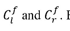
- Figure 12 illustrates plots of the original (C l ) and transformed horizontal coordinates of the left view at various scale/shift factors (s 1 , s 2 ).
- the dashed curve 1202 indicates a reference curve where
- the disparities (d) of corresponding points in the stereo view can be computed by Similarly, the disparities ( of the corresponding points of the transformed stereo view can be computed as Plugging (17) and (18) to (20) gives which demonstrates the relationship between the original disparity (d) and scale/shift applied disparity .
- the perceived disparity would be different from what was intended.
- the range of screen viewable to a user’s eyes is relevant because recent HMDs provide a function to adjust the lens distance. While this function gives flexibility to adapt to people with different IPDs, it may affect the field of view (FOV). So, in this section, whether different IPDs affect FOV enough so that it limits the range of screen reaching a user’s eyes is reviewed. [86] A properly designed HMD hardware assumes that the lens focal length and the lens location are properly set so that it covers all physical screen range.
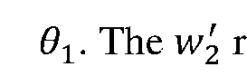
- W 1 ' refers to the screen region ranging from the center of the pupil to the nasal direction until it meets the slit dividing the left/right view.
- the angle formed by this region is denoted Y refers to the screen region ranging from the center of the pupil to the ear direction until it meets end of the physical screen.
- W5 denote the virtual screen generated by the physical screens W respectively, where the dimensions are simply the magnification factor ( ⁇ ) multiplied on its respective physical screen size.
- FIG. 13 shows an example of an effect of IPD on FOV and screen region that can be used with one or more embodiments of the invention.
- Figure 13 illustrates a plot 1302A on how IPD may alter FOVs slightly, but the magnitude difference is not significant, maintaining 79 ⁇ 80 degree of FOV over wide range of IPDs.
- Plot 1302B illustrates how on different IPDs, the screen regions shown to the eyes are constantly at full range. This is also shown in Figure 13 where the effect of IPD cancels out from the equation.
- the goal of this mode is to derive appropriate choices of (s 1 , s 2 ) to apply on scenes or frames so that (d min , d max ) are controlled to stay within the range of s far ⁇ s near without causing any viewing discomfort from negative and/or positive conflict.
- s 1 ⁇ 1 effectively condenses the disparity range into the comfort zone.
- this scaling can create black borders that can be undesirable.
- applying s 2 on the scaled frame provides additional control on the disparities while not introducing additional black borders if operated within the dimensions of already introduced black borders from the scaling factor.
- Figures 14A-C shows examples of a set of scale and shift factors applied to a video frame that can be used with one or more embodiments of the invention.
- a video frame (1400A-C) is scaled (1400A), shifted that is within the existing border (1400B), or shifted beyond the border (1400C).
- b( ⁇ ) following cases should be considered.
- Figure 15 shows an example of a plot of black border that can be used with one or more embodiments of the invention.
- Figure 15 illustrates a plot of black border area V on varying (s 1 , s 2 ).
- the black border area ramps up quickly.
- the optimum solution (1504) will be (s 1 , s 2 ) that gives minimum black border area while satisfying (27) and (28), it is highly likely that the solution will exist on area indicated in region(s) with only b 1 contribution.
- a simple approach of finding the solution for (26) is to perform a full grid search using a full grid search process.
- the (s 1 , s 2 ) combinations can be set to try as below.
- the approach sets (s 1 , s 2 ) search candidates.
- (s 1 , s 2 ) is initially set as such:
- the search range of s 2 is set to be dependent on s 1 as
- the step size of s 1 is set to be a small value of 0.001 to allow high precision on the grid search (although in different embodiments, different step sizes can be used).
- this high precision is of paramount importance for obtaining the most optimal solution, since (1) as the optimization problem aims for the least black border area, the s 1 value of the optimal solution will be driven to larger values and (2) on those considerably large s 1 (close to 1) even the small differences of 0.001 gives room for s 2 to shift a few more pixels that may help meet condition (27) and (28). It is also shown from the experimental result section that the optimal solutions often require control on the scale factors with precision at (or higher than) third decimal digit.
- Such precision setting yields ⁇ 87K combinations of (s 1 , s 2 ).
- a table for black border area is constructed: Considering that the black border area is deterministic with given (s 1 , s 2 ), the black border areas can be pre-computed and stored as a table instead of computing it every time.
- the generated table T b is stored and is loaded up when the decoder initializes. There are ⁇ 87K rows with each row consisting of three numbers. If stored in double precision which is 8B, the memory size required is ⁇ 2 MB.
- the full grid search process loops through the (s 1 , s 2 ) combinations on T b to find ones that meets (27) and (28). Whenever the full grid search process meets such condition, the full grid search process checks on the black border area of the corresponding (s 1 , s 2 ) by referring to T b and update it as the optimal scale/shift solution if it gave smaller black border area compared to the ones so far.
- the Efficient-search method achieves this by deriving a closed form solution of optimal s 1 as a function of s 2 . By doing so, an efficient search process does not need to multiplicatively increase the number of search candidates for the sake of s 1 precision, since the solution is derived mathematically. Instead, the efficient search process just needs to sweep through a certain search range of s 2 which is much less than the Full-search case. [103] In one embodiment, the problem formulation is revisited.
- Figure 16 shows an example of a comparison of optimal scale factor, optimal shift factor, and black border area that can be used with one or more embodiments of the invention.
- Figure 16 illustrates the optimal scale factor (s 1 ) (1602) and optimal shift factor (s 2 ) (1604) derived on example content using Full-search and Efficient- search method.
- the Efficient search can be used as a method for deriving optimal (s 1 , s 2 ).
- the (s 1 , s 2 ) decisions makes on different contents and how they affect disparity statistics are covered.
- the mode receives the finalized comfort zone disparity thresholds (s far , s near ) and the disparity statistics (d min , d max ) of the content.
- the goal of this mode is to derive appropriate choices of (s 1 , s 2 ) to apply on scenes or frames so that (d min , d max ) gets as close to either s far or s near but not crossing it.
- the mode is intended to maximize sense of depth either in positive or negative disparity directions without causing viewing discomfort from positive or negative conflicts, respectively.
- the Adventure Mode procedure is formulated as an optimization problem and show how the solution is derived. [109] As described above, having s 1 > 1 stretches the disparity range outwards, which can be a desirable property for Adventure mode which need to stretch small magnitude disparities close to the comfort zone disparity thresholds. However, upscaling frames introduce cropped- out area in which that should be minimize since content could be lost from original scenes. Similarly, to the Comfort mode, applying s 2 on the scaled-up frame provides additional control on the disparities while not adding on to the cropped-out area if operated within the dimensions of the introduced cropped-out regions.
- the Adventure mode can be formulated as subject to
- the objective function b 1 ( ⁇ ) in (36) is now modified to represent cropped-out area from 1 ⁇ + ⁇ as indicated in (37).
- the range of s 2 that limits the cropped-out area with only b 1 ( ⁇ ) is now modified accordingly as in (38).
- the most notable changes compared to Comfort mode formulation are the conditions (39) and (40).
- Previously the Comfort mode aimed at meeting both inequalities (27) and (28) to make sure the extremes of transformed disparities reside inside the zone of comfort [+ ⁇ , + ⁇ ].
- the aim of Adventure mode is different, in that it tries to bring transformed disparities as close as possible to one of the thresholds ( s near or s far ) . Therefore, the conditions have now changed to equalities and either one of (39) or (40) is taken depending on which threshold is closer to the disparity statistics which are determined as below.
- the disparity statistics are closer to s far .
- the disparity statistics are closer to s near .
- a closed form solution for s 1 is derived. Considering that b 1 ( ⁇ ) in (36) is a monotonically increasing function on 1 ⁇ s 1 , it is favorable to have the smallest possible s 1 that meets all the constraints.
- the next step is to sweep through a range of values of s 2 to derive an optimal (s 1 , s 2 ), where the range is set as avoid the cases of up-sampling the views to a factor higher than s bound .
- the s 2 sweep range becomes [-96, 96].
- a corresponding + ⁇ that minimizes the cropped-out area can be derived using (41).
- a (s 1 , s 2 ) pair is chosen with the smallest s 1 value since it minimizes the objective function of (36).
- the Scale/Shift Application module receives the scale/shift factors (s 1 , s 2 ) determined from the scale/shift parameter decision process, left (l l ) and right views (l r ) from the video decoder, and MODE_FLAG from the User Specified Input. Based on the received inputs the module outputs the scale/shift applied output video that are displayed on HMDs.
- the module outputs the scale/shift applied output video that are displayed on HMDs.
- Figure 17 shows an example of an effect of shift and/or scale for comfort and adventure modes that can be used with one or more embodiments of the invention.
- the Comfort mode case shown in 1702A-B, 1704A-B of Figure 17, involves 0 ⁇ + ⁇ ⁇ 1 which causes the views to be downscaled. Due to this, border area appears between the on-screen area, indicated as shaded, and the scaled down content area, indicated with a dotted line surrounding the “ ”. This scaled down content area may take different part of the on-screen area depending on the given s 2 . So, the overall procedures for generating output video for the Comfort mode will be to generate buffer planes that are initialized to zeros (black), then fill in the appropriate regions for each view based on the given (s 1 , s 2 ).
- the Adventure mode shown in 1706A-B, 1708A-B of Figure 17, involves 1 which generates views that are larger than the on-screen area.
- the scaled-up views are cropped to the screen resolution.
- the crop area may not be center aligned. So, the overall procedure here will be upscaling the views, and cropping them out on appropriate regions based on the given (s 1 , s 2 ).
- attention is needed when processing s 2 on different modes. As discussed above, s 2 affects the coordinates of each view according to (17) and (18). In the case of Comfort mode, the direction to move the content area is consistent with the formerly defined coordinate shift direction.
- s 2 > 0 can be applied by shifting the content area of the left view to the right, and the right view to the left, thereby pulling the coordinates of both views toward each other.
- the content coordinate is not controlled but the offset directions for the on-screen area can be controlled.
- This on-screen area offset direction and the coordinate shift direction are in relative relation, where the direction becomes opposite to each other.
- the on-screen area should be pushed further away from each other as shown in the arrows of Adventure mode of Figure 17.
- Figure 18 shows, in a flow diagram, an example of a scale/shift application that can be used with one or more embodiments of the invention.
- Figure 18 illustrates the overall flow diagram of Scale/Shift Application process 1800.
- the process 1800 receives the inputs that are scale/shift factors (s 1 , s 2 ) from the Scale/Shift Parameter decision module (1802), left (l l ) and right views (l l ) from the video decoder (1804), and MODE_FLAG from the User Specified Input (1806).
- bicubic interpolation can be used for generating these down sampled views.
- another kind of interpolation method can be used for generating these down sampled views.
- process 1800 applies s 1 on to generate & respectively. Sin have resolutions that are greater than or equal to those of For generating these up sampled views, bicubic interpolation or another kind of interpolation method can be used.
- Process 1800 generates (1816) the output views by cropping the area specified by and and saving them to the output buffer Execution proceeds to 1824. At 1824, process 1800 outputs the views [131]
- Figure 19 shows an example of a data processing system 1900 that can be used by or in a camera or other device to provide one or more embodiments described herein.
- the systems and methods described herein can be implemented in a variety of different data processing systems and devices, including general-purpose computer systems, special purpose computer systems, or a hybrid of general purpose and special purpose computer systems.
- Figure 19 is a block diagram of data processing system 1900 hardware according to an embodiment. Note that while Figure 19 illustrates the various components of a data processing system, it is not intended to represent any particular architecture or manner of interconnecting the components as such details are not germane to the present invention. It will also be appreciated that other types of data processing systems that have fewer components than shown or more components than shown in Figure 19 can also be used with one or more embodiments of the present invention.
- the data processing system 1900 includes one or more buses 1909 that serve to interconnect the various components of the system.
- the system in Figure 19 can include a camera or be coupled to a camera.
- One or more processing devices 1903 are coupled to the one or more buses 1909 as is known in the art.
- Memory 1905 may be DRAM or non-volatile RAM or may be flash memory or other types of memory or a combination of such memory devices. This memory is coupled to the one or more buses 1909 using techniques known in the art.
- the data processing system can also include non-volatile memory 1907, which may be a hard disk drive or a flash memory or a magnetic optical drive or magnetic memory or an optical drive or other types of memory systems that maintain data even after power is removed from the system.
- the non-volatile memory 1907 and the memory 1905 are both coupled to the one or more buses 1909 using known interfaces and connection techniques.
- a display controller 1921 is coupled to the one or more buses 1909 in order to receive display data to be displayed on a display device which can be one of displays.
- the data processing system 1900 can also include one or more input/output (I/0) controllers 1915 which provide interfaces for one or more I/0 devices, such as one or more cameras, touch screens, ambient light sensors, and other input devices including those known in the art and output devices (e.g., speakers).
- the input/output devices 1917 are coupled through one or more I/0 controllers 1915 as is known in the art.
- the ambient light sensors can be integrated into the system in Figure 19.
- FIG. 19 shows that the non-volatile memory 1907 and the memory 1905 are coupled to the one or more buses directly rather than through a network interface
- the present invention can utilize non-volatile memory that is remote from the system, such as a network storage device which is coupled to the data processing system through a network interface such as a modem or Ethernet interface.
- the buses 1909 can be connected to each other through various bridges, controllers and/or adapters as is well known in the art.
- the I/0 controller 1915 includes one or more of a USB (Universal Serial Bus) adapter for controlling USB peripherals, an IEEE 1394 controller for IEEE 1394 compliant peripherals, or a Thunderbolt controller for controlling Thunderbolt peripherals.
- USB Universal Serial Bus
- one or more network device(s) 1925 can be coupled to the bus(es) 1909.
- the network device(s) 1925 can be wired network devices (e.g., Ethernet) or wireless network devices (e.g., Wi-Fi, Bluetooth) that receive images from a camera, etc.
- wired network devices e.g., Ethernet
- wireless network devices e.g., Wi-Fi, Bluetooth
- Embodiment 1 is a method comprising: computing, with a decoding device, a comfort threshold using a parameter input by a user.
- Embodiment 2 is a method of embodiment 1 wherein the inputted parameter is one or more of interpupillary distance (IPD) screen distance, screen size, and pixels/screen.
- Embodiment 3 is a method of embodiment 2, wherein the computing of the comfort threshold comprises: computing the comfort threshold using the IPD, screen distance, screen size, and pixels/screen.
- Embodiment 4 is a method of embodiment 1, wherein the post-processing factor is one or more of a scale factor and a shift factor.
- Embodiment 5 is a method of embodiment 4, wherein the processing the stereo video stream comprises: scaling the stereo video stream using the scaling factor.
- Embodiment 6 is a method of embodiment 4, wherein the processing the stereo video stream comprises: shifting each pair of frames in the stereo video stream using the shifting factor, wherein a shifting includes shifting a left side frame towards a corresponding right side frame or shifting the left side frame away from the corresponding right side frame.
- Embodiment 7 is a method of embodiment 1, wherein the computing of the post- processing factor includes: retrieving disparity statistics from the metadata, wherein the disparity statistics include the indications of disparities between corresponding left and right frames of the stereo video stream; retrieving comfort threshold; and computing the post-processing factor using the disparity statistics and comfort threshold.
- Embodiment 8 is a method of embodiment 7, wherein the disparity statistics are the range of disparities that a frame of the video stream covers.
- Embodiment 9 is a method of embodiment 7, wherein the disparity statistics are computed by an encoding device that encoded the stereo video stream.
- Embodiment 10 is a method of embodiment 7, wherein the disparity statistics includes (d min , d max ) values for each frame.
- Embodiment 11 is a method of embodiment 7, wherein the input mode is one of a comfort mode and an adventure mode, the comfort mode reduces a sense of depth and is used when stereo video stream includes a disparity that is outside a comfort zone range, and the adventure mode increases the sense of depth and is used when the disparity is within the comfort zone range.
- Embodiment 12 is a method of embodiment 1, wherein the computing of the post- processing factor uses at least one of an input mode and a threshold control.
- Embodiment 13 is a method of embodiment 1, wherein the processing further comprises minimizing a border around at least one of video stream of the stereo video stream.
- Embodiment 14 is a method of embodiment 13, wherein the minimizing further comprises creating a set of possible scale and shift factor pairs, wherein each of the possible scale and shift factor pairs is associated with a border area value and determining a final scale and shift factor pair from the set of possible scale and shift factor pairs that minimizes the border area value.
- Embodiment 15 is a method of embodiment 13, wherein the minimizing comprises determining a set of scale factor upper bound candidates, selecting a minimum scale factor from the set of scale factor upper bound candidates that, performing a sweep of shift factors using the selected scale factor to determine a final shift factor, and returning the selected scale factor and final shift factor.
- Embodiment 16 is a method of embodiment 1, wherein the processing further comprises determining that a mode is a comfort mode, applying a scale factor to a left and right view of the stereo video stream to generate scaled left and right views, wherein the resolutions of the scaled views are equal to or less than the resolution of the un-scaled views, setting a set of fill-in coordinates using a scale and the shift factor, and pasting the scaled views into the un-scaled views in an area associated with the set of fill-in coordinates.
- Embodiment 16 is a method of embodiment 1, wherein the processing further comprises determining that a mode is an adventure mode, applying a scale factor to a left and right view of the stereo video stream to generate scaled left and right views, wherein the resolutions of the scaled views are greater than or equal to the resolution of the un- scaled views, setting a set of crop coordinates using a scale and the shift factor; and cropping an area associated with the set of crop coordinates of the scaled views into the un-scaled views.
- Embodiment 17 is a method of embodiment 1, wherein the processing further comprises determining that a mode is an adventure mode, applying a scale factor to a left and right view of the stereo video stream to generate scaled left and right views, wherein the resolutions of the scaled views are greater than or equal to the resolution of the un-scaled views setting a set of crop coordinates using a scale and the shift factor, and cropping an area associated with the set of crop coordinates of the scaled views into the un-scaled views.
- Embodiment 18 is a method of embodiment 1, wherein the processing further comprises minimizing a crop-out area for at least one of video stream of the stereo video stream.
- Embodiment 19 is a method of embodiment 18, wherein the minimizing further comprises creating a set of possible scale and shift factor pairs, wherein each of the possible scale and shift factor pairs is associated with a crop-out area value and determining a final scale and shift factor pair from the set of possible scale and shift factor pairs that minimizes the cop-out area value.
- Embodiment 20 is a method of embodiment 18, wherein the minimizing factor comprises determining a set of scale factor lower bound candidates, selecting a scale factor from the set of scale factor lower bound candidates that is a maximum, performing a sweep of shift factors using the selected scale factor to determine a final shift factor, and returning the selected scale factor and final shift factor.
- Embodiment 21 is an apparatus comprising a processing system and memory and configured to perform any one of the methods in claims 1-19.
- Embodiment 22 is a non-transitory machine-readable storage storing executable program instructions which when executed by a machine cause the machine to perform any one of the methods of claims 1-19.
- a storage medium such as a non- transitory machine- readable storage medium (e.g., DRAM or flash memory).
- a method comprising: computing, with a decoding device, a comfort threshold using a parameter input by a user; receiving a stereo video stream and metadata corresponding to the stereo video stream, wherein the metadata includes an indication of disparities between a corresponding left and right frame of the stereo video stream; computing a post-processing factor for the stereo video stream using the metadata and comfort threshold; and processing the stereo video stream using the post-processing factor.
- EEE 2 The method of EEE 1 wherein the inputted parameter includes one or more of interpupillary distance (IPD) screen distance, screen size, and pixels/screen.
- IPD interpupillary distance
- the computing of the comfort threshold comprises: computing the comfort threshold using the IPD, screen distance, screen size, and pixels/screen.
- EEE 5 The method of any one of EEEs 1 to 3, wherein the post-processing factor is one or more of a scale factor and a shift factor.
- EEE 5 The method of EEE 4, wherein the processing the stereo video stream comprises: scaling the stereo video stream using the scaling factor.
- EEE 6 The method of EEE 4, wherein the processing the stereo video stream comprises: shifting each pair of frames in the stereo video stream using the shifting factor, wherein a shifting includes shifting a left side frame towards a corresponding right side frame or shifting the left side frame away from the corresponding right side frame.
- the computing of the post- processing factor includes: retrieving disparity statistics from the metadata, wherein the disparity statistics include the indications of disparities between corresponding left and right frames of the stereo video stream; retrieving comfort threshold; and computing the post-processing factor using the disparity statistics and comfort threshold.
- any one of EEEs 7 to 10 wherein the input mode is one of a comfort mode and an adventure mode, the comfort mode reduces a sense of depth and is used when stereo video stream includes a disparity that is outside a comfort zone range, and the adventure mode increases the sense of depth and is used when the disparity is within the comfort zone range.
- EEE 12 The method of any one of EEEs 1 to 11, wherein the computing of the post-processing factor uses at least one of an input mode and a threshold control.
- EEE 13 The method of any one of EEEs 1 to 12, wherein the processing further comprises: minimizing a border around at least one of video stream of the stereo video stream.
- EEE 15 The method of EEE 13 or 14, wherein the minimizing further comprises: determining a set of scale factor upper bound candidates; selecting a scale factor from the set of scale factor upper bound candidates that is minimum; performing a sweep of shift factors using the selected scale factor to determine a final shift factor; and. returning the selected scale factor and final shift factor.
- any one of EEEs 1 to 16 wherein the processing further comprises: determining that a mode is an adventure mode; applying a scale factor to a left and right view of the stereo video stream to generate scaled left and right views, wherein the resolutions of the scaled views are greater than or equal to the resolution of the un-scaled views; setting a set of crop coordinates using a scale and the shift factor; and cropping an area associated with the set of crop coordinates of the scaled views into the un-scaled views.
- EEE 18 The method of any one of EEEs 1 to 17, wherein the processing further comprises: minimizing a crop-out area for at least one of video stream of the stereo video stream.
- EEE 19
- EEE 18 further comprises: creating a set of possible scale and shift factor pairs, wherein each of the possible scale and shift factor pairs is associated with a border area value; and determining a final scale and shift factor pair from the set of possible scale and shift factor pairs that maximizes the border area value.
- EEE 20 The method of EEE 18 or 19, wherein the minimizing further comprises: determining a set of scale factor lower bound candidates; selecting a scale factor from the set of scale factor lower bound candidates that is a maximum; performing a sweep of shift factors using the selected scale factor to determine a final shift factor; and. returning the selected scale factor and final shift factor.
- EEE 21 An apparatus comprising a processing system and memory and configured to perform any one of the methods in EEEs 1-20.
- EEE 22 A non-transitory machine-readable storage storing executable program instructions which when executed by a machine cause the machine to perform any one of the methods of EEEs 1-20.
Landscapes
- Engineering & Computer Science (AREA)
- Multimedia (AREA)
- Signal Processing (AREA)
- Library & Information Science (AREA)
- Testing, Inspecting, Measuring Of Stereoscopic Televisions And Televisions (AREA)
Abstract
Description












Claims
Priority Applications (1)
| Application Number | Priority Date | Filing Date | Title |
|---|---|---|---|
| EP24737843.3A EP4725190A1 (en) | 2023-06-12 | 2024-06-05 | Head-mounted display adjustment methods and systems |
Applications Claiming Priority (4)
| Application Number | Priority Date | Filing Date | Title |
|---|---|---|---|
| US202363507726P | 2023-06-12 | 2023-06-12 | |
| US63/507,726 | 2023-06-12 | ||
| EP23184926.6 | 2023-07-12 | ||
| EP23184926 | 2023-07-12 |
Publications (1)
| Publication Number | Publication Date |
|---|---|
| WO2024258716A1 true WO2024258716A1 (en) | 2024-12-19 |
Family
ID=91759581
Family Applications (1)
| Application Number | Title | Priority Date | Filing Date |
|---|---|---|---|
| PCT/US2024/032625 Ceased WO2024258716A1 (en) | 2023-06-12 | 2024-06-05 | Head-mounted display adjustment methods and systems |
Country Status (2)
| Country | Link |
|---|---|
| EP (1) | EP4725190A1 (en) |
| WO (1) | WO2024258716A1 (en) |
Citations (3)
| Publication number | Priority date | Publication date | Assignee | Title |
|---|---|---|---|---|
| US20120120200A1 (en) * | 2009-07-27 | 2012-05-17 | Koninklijke Philips Electronics N.V. | Combining 3d video and auxiliary data |
| US20120127155A1 (en) * | 2010-11-23 | 2012-05-24 | Sharp Laboratories Of America, Inc. | 3d comfort and fusion limit empirical model |
| US20200177862A1 (en) * | 2017-08-30 | 2020-06-04 | Innovations Mindtrick Inc. | Viewer-adjusted stereoscopic image display |
-
2024
- 2024-06-05 WO PCT/US2024/032625 patent/WO2024258716A1/en not_active Ceased
- 2024-06-05 EP EP24737843.3A patent/EP4725190A1/en active Pending
Patent Citations (3)
| Publication number | Priority date | Publication date | Assignee | Title |
|---|---|---|---|---|
| US20120120200A1 (en) * | 2009-07-27 | 2012-05-17 | Koninklijke Philips Electronics N.V. | Combining 3d video and auxiliary data |
| US20120127155A1 (en) * | 2010-11-23 | 2012-05-24 | Sharp Laboratories Of America, Inc. | 3d comfort and fusion limit empirical model |
| US20200177862A1 (en) * | 2017-08-30 | 2020-06-04 | Innovations Mindtrick Inc. | Viewer-adjusted stereoscopic image display |
Also Published As
| Publication number | Publication date |
|---|---|
| EP4725190A1 (en) | 2026-04-15 |
Similar Documents
| Publication | Publication Date | Title |
|---|---|---|
| US11290699B2 (en) | View direction based multilevel low bandwidth techniques to support individual user experiences of omnidirectional video | |
| US10694170B2 (en) | Controlling image display via real-time compression in peripheral image regions | |
| US20220414823A1 (en) | Virtual reality cinema-immersive movie watching for headmounted displays | |
| US10560680B2 (en) | Virtual reality with interactive streaming video and likelihood-based foveation | |
| US9924153B2 (en) | Parallel scaling engine for multi-view 3DTV display and method thereof | |
| US10154244B2 (en) | 3D system including a marker mode | |
| US20240196065A1 (en) | Information processing apparatus and information processing method | |
| TWI528781B (en) | Method and apparatus for customizing three-dimensional effects of stereoscopic content | |
| US9729845B2 (en) | Stereoscopic view synthesis method and apparatus using the same | |
| CN111652921B (en) | Monocular depth prediction model generation method and monocular depth prediction method | |
| US12174377B2 (en) | Image processing method and apparatus for head-mounted display device as well as electronic device | |
| CN109191506B (en) | Depth map processing method, system and computer readable storage medium | |
| US11962819B2 (en) | Foviation and HDR | |
| CN112470484A (en) | Partial shadow and HDR | |
| CN106303498B (en) | Video display control method and device, display equipment | |
| WO2021031210A1 (en) | Video processing method and apparatus, storage medium, and electronic device | |
| EP4720816A1 (en) | Rendering layers with different perception quality | |
| US12413693B2 (en) | Processing of extended dimension light field images | |
| CN103843335A (en) | Image processing device, image processing method and program | |
| US20240267559A1 (en) | Information processing apparatus and information processing method | |
| EP4725190A1 (en) | Head-mounted display adjustment methods and systems | |
| TWI772102B (en) | Method for transmitting reduced depth information and electronic system | |
| JP2013535120A (en) | Method and apparatus for auto-convergence based on auto-focus points for stereoscopic frames | |
| US20140204175A1 (en) | Image conversion method and module for naked-eye 3d display | |
| WO2014038476A1 (en) | Stereoscopic image processing device, stereoscopic image processing method, and program |
Legal Events
| Date | Code | Title | Description |
|---|---|---|---|
| 121 | Ep: the epo has been informed by wipo that ep was designated in this application |
Ref document number: 24737843 Country of ref document: EP Kind code of ref document: A1 |
|
| ENP | Entry into the national phase |
Ref document number: 2024737843 Country of ref document: EP Effective date: 20260112 |
|
| WWE | Wipo information: entry into national phase |
Ref document number: 2024737843 Country of ref document: EP |
|
| NENP | Non-entry into the national phase |
Ref country code: DE |
|
| ENP | Entry into the national phase |
Ref document number: 2024737843 Country of ref document: EP Effective date: 20260112 |
|
| ENP | Entry into the national phase |
Ref document number: 2024737843 Country of ref document: EP Effective date: 20260112 |
|
| ENP | Entry into the national phase |
Ref document number: 2024737843 Country of ref document: EP Effective date: 20260112 |
|
| ENP | Entry into the national phase |
Ref document number: 2024737843 Country of ref document: EP Effective date: 20260112 |
|
| WWP | Wipo information: published in national office |
Ref document number: 2024737843 Country of ref document: EP |