WO2024257786A1 - 復号装置、復号方法、符号化装置、符号化方法、及び、装置 - Google Patents
復号装置、復号方法、符号化装置、符号化方法、及び、装置 Download PDFInfo
- Publication number
- WO2024257786A1 WO2024257786A1 PCT/JP2024/021298 JP2024021298W WO2024257786A1 WO 2024257786 A1 WO2024257786 A1 WO 2024257786A1 JP 2024021298 W JP2024021298 W JP 2024021298W WO 2024257786 A1 WO2024257786 A1 WO 2024257786A1
- Authority
- WO
- WIPO (PCT)
- Prior art keywords
- data
- dimensional
- vertices
- unit
- information
- Prior art date
- Legal status (The legal status is an assumption and is not a legal conclusion. Google has not performed a legal analysis and makes no representation as to the accuracy of the status listed.)
- Ceased
Links
Images


































Classifications
-
- G—PHYSICS
- G06—COMPUTING OR CALCULATING; COUNTING
- G06T—IMAGE DATA PROCESSING OR GENERATION, IN GENERAL
- G06T9/00—Image coding
- G06T9/001—Model-based coding, e.g. wire frame
-
- G—PHYSICS
- G06—COMPUTING OR CALCULATING; COUNTING
- G06T—IMAGE DATA PROCESSING OR GENERATION, IN GENERAL
- G06T9/00—Image coding
-
- G—PHYSICS
- G06—COMPUTING OR CALCULATING; COUNTING
- G06T—IMAGE DATA PROCESSING OR GENERATION, IN GENERAL
- G06T9/00—Image coding
- G06T9/40—Tree coding, e.g. quadtree, octree
-
- H—ELECTRICITY
- H04—ELECTRIC COMMUNICATION TECHNIQUE
- H04N—PICTORIAL COMMUNICATION, e.g. TELEVISION
- H04N19/00—Methods or arrangements for coding, decoding, compressing or decompressing digital video signals
- H04N19/30—Methods or arrangements for coding, decoding, compressing or decompressing digital video signals using hierarchical techniques, e.g. scalability
-
- H—ELECTRICITY
- H04—ELECTRIC COMMUNICATION TECHNIQUE
- H04N—PICTORIAL COMMUNICATION, e.g. TELEVISION
- H04N19/00—Methods or arrangements for coding, decoding, compressing or decompressing digital video signals
- H04N19/30—Methods or arrangements for coding, decoding, compressing or decompressing digital video signals using hierarchical techniques, e.g. scalability
- H04N19/33—Methods or arrangements for coding, decoding, compressing or decompressing digital video signals using hierarchical techniques, e.g. scalability in the spatial domain
-
- H—ELECTRICITY
- H04—ELECTRIC COMMUNICATION TECHNIQUE
- H04N—PICTORIAL COMMUNICATION, e.g. TELEVISION
- H04N19/00—Methods or arrangements for coding, decoding, compressing or decompressing digital video signals
- H04N19/44—Decoders specially adapted therefor, e.g. video decoders which are asymmetric with respect to the encoder
-
- H—ELECTRICITY
- H04—ELECTRIC COMMUNICATION TECHNIQUE
- H04N—PICTORIAL COMMUNICATION, e.g. TELEVISION
- H04N19/00—Methods or arrangements for coding, decoding, compressing or decompressing digital video signals
- H04N19/46—Embedding additional information in the video signal during the compression process
-
- H—ELECTRICITY
- H04—ELECTRIC COMMUNICATION TECHNIQUE
- H04N—PICTORIAL COMMUNICATION, e.g. TELEVISION
- H04N19/00—Methods or arrangements for coding, decoding, compressing or decompressing digital video signals
- H04N19/50—Methods or arrangements for coding, decoding, compressing or decompressing digital video signals using predictive coding
- H04N19/597—Methods or arrangements for coding, decoding, compressing or decompressing digital video signals using predictive coding specially adapted for multi-view video sequence encoding
-
- H—ELECTRICITY
- H04—ELECTRIC COMMUNICATION TECHNIQUE
- H04N—PICTORIAL COMMUNICATION, e.g. TELEVISION
- H04N19/00—Methods or arrangements for coding, decoding, compressing or decompressing digital video signals
- H04N19/70—Methods or arrangements for coding, decoding, compressing or decompressing digital video signals characterised by syntax aspects related to video coding, e.g. related to compression standards
Definitions
- This disclosure relates to a decoding device, a decoding method, an encoding device, an encoding method, and an apparatus.
- 3D data can be acquired in a variety of ways, including distance sensors such as range finders, stereo cameras, or a combination of multiple monocular cameras.
- One method of expressing three-dimensional data is a method called a point cloud, which uses a group of points in three-dimensional space to represent the shape of a three-dimensional structure.
- a point cloud In a point cloud, the position and color of the point cloud are stored.
- Point clouds are expected to become the mainstream method of expressing three-dimensional data, but point clouds have a very large amount of data. Therefore, when storing or transmitting three-dimensional data, it is essential to compress the amount of data by encoding, just as with two-dimensional moving images (examples include MPEG-4 AVC or HEVC standardized by MPEG).
- Patent Document 1 There is also known technology that uses three-dimensional map data to search for and display facilities located around a vehicle (see, for example, Patent Document 1).
- the present disclosure aims to provide a decoding device and the like that can output three-dimensional data with different resolutions.
- a decoding device includes a circuit and a memory connected to the circuit, and the circuit, in operation, acquires encoded data, restores a plurality of first vertices based on the encoded data, connects the restored first vertices to generate first surface information including a first surface, restores a plurality of second vertices based on the encoded data and the first surface, connects points including the restored first vertices and the restored second vertices to generate second surface information including a second surface, and outputs the plurality of first vertices, the plurality of second vertices, the first surface information, and the second surface information.
- An encoding device includes a circuit and a memory connected to the circuit, and the circuit, in operation, determines a plurality of first vertices of a three-dimensional object, connects the plurality of first vertices to generate first surface information including a first surface, determines a plurality of second vertices based on the first surface, connects a point cloud including the plurality of first vertices and the plurality of second vertices to generate second surface information including a second surface, and generates encoded data including the plurality of first vertices, the plurality of second vertices, the first surface information, and the second surface information.
- the device includes a circuit and a memory connected to the circuit, and in operation, the circuit determines the type of three-dimensional data to be decoded and extracts the determined type of three-dimensional data from the encoded data, the encoded data including (1) a plurality of first vertices of a three-dimensional object, (2) first surface information including a first surface generated by connecting the plurality of first vertices, (3) a plurality of second vertices determined based on the first surface, and (4) a second surface generated by connecting a point cloud including the plurality of first vertices and the plurality of second vertices, the type of the extracted three-dimensional data includes a first format and a second format, and when the type of the three-dimensional data to be decoded is determined to be the first format, first encoded data including the plurality of first vertices and the first surface information is extracted, and when the type of the three-dimensional data to be decoded is determined to be the second format, second encoded data including the first
- the decoding device disclosed herein can output three-dimensional data at different resolutions.
- FIG. 1 is a diagram showing an example of a configuration of a three-dimensional data encoding/decoding system according to a first embodiment.
- FIG. 2 is a diagram showing a configuration of point cloud data in the first embodiment.
- FIG. 3 is a diagram showing an example of a configuration of a data file in which information on point cloud data is described in the first embodiment.
- FIG. 4 is a diagram showing a structure of three-dimensional mesh data in the first embodiment.
- FIG. 5 is a diagram showing an example of the structure of a data file in which information on three-dimensional mesh data is described in the first embodiment.
- FIG. 6 is a diagram for explaining a three-dimensional model in the first embodiment.
- FIG. 7 is a diagram showing types of three-dimensional data in the first embodiment.
- FIG. 1 is a diagram showing an example of a configuration of a three-dimensional data encoding/decoding system according to a first embodiment.
- FIG. 2 is a diagram showing a configuration of point cloud data in the first embodiment.
- FIG. 8 is a diagram for explaining the encoding process of three-dimensional data in the first embodiment.
- FIG. 9 is a diagram for explaining the decoding process of three-dimensional data in the first embodiment.
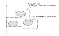
- FIG. 10 is a diagram showing tiles and slices of three-dimensional data in a two-dimensional manner according to the first embodiment.
- FIG. 11 is a diagram showing an example of a terminal presentation screen that can be switched in response to a user request in the first embodiment.
- FIG. 12 is a diagram showing an example of a terminal presentation screen that is automatically switched in response to a user operation in the first embodiment.
- FIG. 13 is a block diagram showing an example of a functional configuration of the server and the terminal in the first embodiment. As shown in FIG. FIG. FIG.
- FIG. 14 is a block diagram showing another example of the data generating unit of the server in the first embodiment.
- FIG. 15 is a diagram for explaining the synchronization process of the coordinate systems in the first embodiment.
- FIG. 16 is a diagram for explaining the synchronization process of the coordinate systems in the first embodiment.
- FIG. 17 is a diagram for explaining the relationship between three-dimensional space and encoded data in the first embodiment.
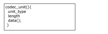
- FIG. 18 is a diagram showing an example of the syntax of a coding method unit in the first embodiment.
- FIG. 19 is a diagram showing an example of the syntax of the coded point group in the first embodiment.
- FIG. 20 is a diagram showing an example of the syntax of a coding mesh in the first embodiment.
- FIG. 21 is a diagram showing an example of the syntax of the encoded 3D model in the first embodiment.
- FIG. 22 is a diagram showing an example of the syntax of three-dimensional data information in the first embodiment.
- FIG. 23 is a diagram illustrating the data structure of an encoded point group in the first embodiment.
- FIG. 24 is a diagram for explaining the data structure of an encoded mesh in embodiment 1.
- FIG. 25 is a diagram illustrating the data structure of an encoded 3D model in the first embodiment.
- FIG. 26 is a two-dimensional diagram illustrating an example of a plurality of three-dimensional spaces in accordance with the first embodiment.
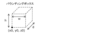
- FIG. 27 is a diagram showing an example of a bounding box in the first embodiment.
- FIG. 28 is a diagram showing an example of the syntax of three-dimensional space information in the first embodiment.
- FIG. 29 is a flowchart showing an example of partial decoding in the first embodiment.
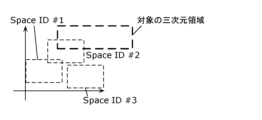
- FIG. 30 is a diagram showing an example of a three-dimensional spatial region to be subjected to partial decoding in the first embodiment.
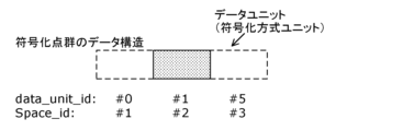
- FIG. 31 is a diagram showing an example of a data structure of a group of partially decoded encoded points in the first embodiment.
- FIG. 32 is a diagram showing an example of a data structure of a partially decoded encoded mesh in embodiment 1.
- FIG. 33 is a diagram showing an example of a data structure of a partially decoded encoded 3D model in the first embodiment.
- FIG. 34 is a diagram showing an example of coordinate systems of different types of three-dimensional data that are not spatially synchronized in the first embodiment.
- FIG. 35 is a diagram showing an example of the syntax of three-dimensional data information in the first embodiment.
- FIG. 36 is a diagram showing an example of the syntax of three-dimensional space information in the first embodiment.
- FIG. 37 is a diagram illustrating an example of a functional configuration of a terminal in the first embodiment.
- FIG. 38 is a flowchart showing an example of spatial synchronization processing in the first embodiment.
- FIG. 39 is a diagram showing an example of the configuration of a decoding device in the first embodiment.
- FIG. 40 is a flowchart showing an example of a decoding method performed by the decoding device in the first embodiment.
- FIG. 40 is a flowchart showing an example of a decoding method performed by the decoding device in the first embodiment.
- FIG. 41 is a flowchart showing another example of a decoding method performed by the decoding device.
- FIG. 42 is a diagram showing an example of the configuration of an encoding device.
- FIG. 43 is a flowchart showing an example of an encoding method by the encoding device.
- FIG. 44 is a diagram illustrating partial decoding for decoding a part of three-dimensional data in the second embodiment.
- FIG. 45 is a diagram illustrating an example of extracting and decoding a part of three-dimensional data in the second embodiment.
- FIG. 46 is a block diagram showing an example of a functional configuration of a server and a terminal in the second embodiment.
- FIG. 47 is a flowchart showing an example of processing by a terminal in the second embodiment.
- FIG. 48 is a diagram showing an example of an original point group in the second embodiment.
- FIG. 49 is a diagram showing an example of a pruned octree in the second embodiment.
- FIG. 50 shows an example of a two-dimensional display of leaf nodes in the second embodiment.
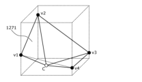
- FIG. 51 is a diagram for explaining a method of generating a centroid vertex in the second embodiment.
- FIG. 52 is a diagram for explaining a method of generating a centroid vertex in the second embodiment.
- FIG. 53 is a diagram showing an example of vertex information in the second embodiment.
- FIG. 54 is a diagram showing an example of a Trisoap surface in the second embodiment.
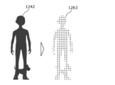
- FIG. 55 is a diagram for explaining the point cloud restoration process in the second embodiment.
- FIG. 56 is a diagram showing an example of the configuration of a decoding unit in the second embodiment.
- FIG. 57 is a diagram showing an example of the syntax of metadata (SEI) in an outputtable format in embodiment 2.
- SEI syntax of metadata
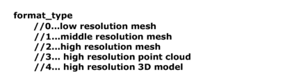
- FIG. 58 is a diagram showing an example of format_type in the second embodiment.
- FIG. 59 is a diagram showing another example of format_type in the second embodiment.
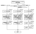
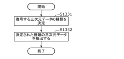
- FIG. 60 is a flowchart showing an example of detailed processing for decoding three-dimensional data in a format specified by a predetermined method in the second embodiment.
- FIG. 61 is a block diagram showing another example of the functional configuration of the server and the terminal in the second embodiment.
- FIG. 62 is a flowchart showing another example of processing by the terminal in the second embodiment.
- FIG. 63 is a diagram showing an example of a structure of a data unit in the second embodiment.
- FIG. 64 is a diagram showing an example of the syntax of a coding method unit in the second embodiment.
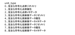
- FIG. 65 is a diagram showing an example of type information in the second embodiment.
- FIG. 66 is a diagram showing an example of a data unit structure for partial transmission in the second embodiment.
- FIG. 67 is a diagram showing an example of a data unit structure for partial transmission in embodiment 2.
- FIG. 68 is a diagram showing an example of a data unit structure for partial transmission in embodiment 2.
- FIG. 69 is a diagram showing an example of the syntax of a coding method unit for partial transmission in the second embodiment.
- FIG. 70 is a diagram showing an example of type information in the second embodiment for partial transmission.
- FIG. FIG. 70 is a diagram showing an example of type information in the second embodiment for partial transmission.
- FIG. 71 is a diagram illustrating a group ID in the second embodiment.
- FIG. 72 is a diagram showing an example of the configuration of a decoding device in the second embodiment.
- FIG. 73 is a flowchart showing an example of a decoding method performed by the decoding device in embodiment 2.
- FIG. 74 is a diagram showing an example of the configuration of a coding device in the second embodiment.
- FIG. 75 is a flowchart showing an example of an encoding method performed by the encoding device in the second embodiment.
- FIG. 76 is a flowchart showing an example of a method performed by a decoding device or an encoding device in embodiment 2.
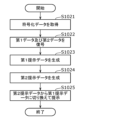
- the decoding device includes a circuit and a memory connected to the circuit, and in operation, the circuit acquires encoded data, restores a plurality of first vertices based on the encoded data, connects the restored first vertices to generate first surface information including a first surface, restores a plurality of second vertices based on the encoded data and the first surface, connects points including the restored first vertices and the restored second vertices to generate second surface information including a second surface, and outputs the plurality of first vertices, the plurality of second vertices, the first surface information, and the second surface information.
- low-resolution information including a plurality of first vertices and first surface information, and high-resolution information including a plurality of second vertices and second surface information are generated and output in two stages, so that, for example, low-resolution three-dimensional data can be output based on the low-resolution information, or high-resolution three-dimensional data with a higher resolution than the low-resolution three-dimensional data can be output based on the low-resolution information and the high-resolution information.
- the decoding device is the decoding device according to the first aspect, and the circuit further generates point cloud data including a plurality of points based on the second surface and outputs the point cloud data.
- the decoding device is the decoding device according to the first or second aspect, and the encoded data includes first encoded data including the first vertices and the first face information, and second encoded data including extension information for decoding the second vertices and the second face.
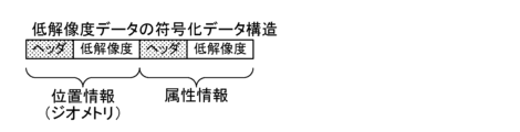
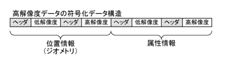
- the decoding device is the decoding device according to the third aspect, in which the encoded data includes a header and a data unit, and the data unit includes the first encoded data and the second encoded data in that order.
- the decoding device is the decoding device according to the third aspect, in which the encoded data includes a first data unit including a first header and the first encoded data, and a second data unit including a second header and the second encoded data.
- the decoding device is the decoding device according to the third aspect, in which the circuit further decodes a portion of the first encoded data and the second encoded data, and outputs either (1) the first encoded data or (2) the first encoded data or the second encoded data.
- the decoding device is the decoding device according to the sixth aspect, in which the circuit further obtains numerical information indicating the number of formats that can be output, and determines the data to be output based on the numerical information.
- the decoding device is the decoding device according to the sixth aspect, in which the circuit further acquires type information indicating the type of format that can be output, and determines the type information and the data to be output.
- the decoding device is the decoding device according to the third aspect, in which the circuit further acquires (1) the first encoded data and (2) either the first encoded data or the second encoded data, and decodes and outputs the acquired (1) first encoded data or (2) the first encoded data and the second encoded data.
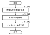
- the encoding device includes a circuit and a memory connected to the circuit, and the circuit, in operation, determines a plurality of first vertices of a three-dimensional object, connects the plurality of first vertices to generate first surface information including a first surface, determines a plurality of second vertices based on the first surface, connects a point cloud including the plurality of first vertices and the plurality of second vertices to generate second surface information including a second surface, and generates encoded data including the plurality of first vertices, the plurality of second vertices, the first surface information, and the second surface information.
- encoded data obtained by generating low-resolution information including a plurality of first vertices and first surface information, and high-resolution information including a plurality of second vertices and second surface information in two stages is output, so that a decoding device that acquires the encoded data can, for example, output low-resolution three-dimensional data based on the low-resolution information, or output high-resolution three-dimensional data with a higher resolution than the low-resolution three-dimensional data based on the low-resolution information and the high-resolution information.
- the encoding device is the encoding device according to the tenth aspect, in which the circuit further generates point cloud data including a plurality of points based on the second surface, and the encoded data further includes the point cloud data.
- the encoding device is the encoding device according to the tenth aspect, in which the circuit further generates first encoded data including the plurality of first vertices and the first face information, and generates second encoded data including the plurality of second vertices and the second face information, and the encoded data includes the first encoded data and the second encoded data.
- a decoding device that acquires the encoded data can restore multiple pieces of three-dimensional data with different resolutions.
- the encoding device is the encoding device according to the twelfth aspect, in which the encoded data includes a header and a data unit, and the data unit includes the first encoded data and the second encoded data in that order.
- the encoding device is the encoding device according to the twelfth aspect, in which the encoded data includes a first data unit including a first header and the first encoded data, and a second data unit including a second header and the second encoded data.
- the encoding device is the encoding device according to the fourteenth aspect, in which the encoded data includes numerical information indicating the number of formats that can be output.
- the encoding device is the encoding device according to the fourteenth aspect, in which the encoded data includes type information indicating the type of format that can be output.
- the encoding device is the encoding device according to the tenth aspect, in which the circuit further outputs (1) the first encoded data, and (2) either the first encoded data or the second encoded data.
- the decoding method reconstructs a plurality of first vertices based on encoded data, connects the reconstructed plurality of first vertices to generate first surface information including a first surface, reconstructs a plurality of second vertices based on the encoded data and the first surface, connects a point cloud including the reconstructed plurality of first vertices and the plurality of second vertices to generate second surface information including a second surface, and outputs the plurality of first vertices, the plurality of second vertices, the first surface information, and the second surface information.
- low-resolution information including a plurality of first vertices and first surface information, and high-resolution information including a plurality of second vertices and second surface information are generated and output in two stages, so that, for example, low-resolution three-dimensional data can be output based on the low-resolution information, or high-resolution three-dimensional data with a higher resolution than the low-resolution three-dimensional data can be output based on the low-resolution information and the high-resolution information.
- the encoding method determines a plurality of first vertices of a three-dimensional object, connects the plurality of first vertices to generate first surface information including a first surface, determines a plurality of second vertices based on the first surface, connects a point cloud including the plurality of first vertices and the plurality of second vertices to generate second surface information including the second surface, and generates encoded data including the plurality of first vertices, the plurality of second vertices, the first surface information, and the second surface information.
- encoded data obtained by generating low-resolution information including a plurality of first vertices and first surface information, and high-resolution information including a plurality of second vertices and second surface information in two stages is output, so that a decoding device that acquires the encoded data can, for example, output low-resolution three-dimensional data based on the low-resolution information, or output high-resolution three-dimensional data with a higher resolution than the low-resolution three-dimensional data based on the low-resolution information and the high-resolution information.
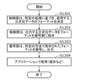
- the device includes a circuit and a memory connected to the circuit, and in operation, the circuit determines the type of three-dimensional data to be decoded and extracts the determined type of three-dimensional data from the encoded data, the encoded data including (1) a plurality of first vertices of a three-dimensional object, (2) first surface information including a first surface generated by connecting the plurality of first vertices, (3) a plurality of second vertices determined based on the first surface, and (4) a second surface generated by connecting a point cloud including the plurality of first vertices and the plurality of second vertices, the type of the extracted three-dimensional data includes a first format and a second format, and when the type of the three-dimensional data to be decoded is determined to be the first format, first encoded data including the plurality of first vertices and the first surface information is extracted, and when the type of the three-dimensional data to be decoded is determined to be the second format, second encoded data including the
- the encoded data required for decoding can be extracted based on the determined format. Therefore, when a format that requires a small amount of data for decoding is selected, the amount of data to be extracted can be reduced, so that, for example, the amount of transmission required for transmitting the encoded data can be reduced, and the processing load of the decoding process by the decoding device that has acquired the encoded data can be reduced.
- FIG. 1 is a diagram showing an example of the configuration of a three-dimensional data encoding/decoding system according to this embodiment.
- the three-dimensional data encoding/decoding system includes a three-dimensional data encoding system 1001, a three-dimensional data decoding system 1002, a sensor terminal 1003, and an external connection unit 1004.
- the three-dimensional data encoding system 1001 generates encoded data or multiplexed data by encoding three-dimensional data.
- the three-dimensional data encoding system 1001 may be a three-dimensional data encoding device realized by a single device, or may be a system realized by multiple devices.
- the three-dimensional data encoding device may also include some of the multiple processing units included in the three-dimensional data encoding system 1001.
- the three-dimensional data encoding system 1001 includes a three-dimensional data generation system 1011, a presentation unit 1012, an encoding unit 1013, a multiplexing unit 1014, an input/output unit 1015, and a control unit 1016.
- the three-dimensional data generation system 1011 includes a sensor information acquisition unit 1017 and a three-dimensional data generation unit 1018.
- the sensor information acquisition unit 1017 acquires a sensor signal from the sensor terminal 1003 and outputs the sensor signal to the three-dimensional data generation unit 1018.
- the three-dimensional data generation unit 1018 generates three-dimensional data from the sensor signal and outputs the three-dimensional data to the encoding unit 1013.
- the presentation unit 1012 presents the sensor signal or the three-dimensional data to the user. For example, the presentation unit 1012 displays information or an image based on the sensor signal or the three-dimensional data.
- the encoding unit 1013 encodes (compresses) the three-dimensional data, and outputs the resulting encoded data, control information obtained in the encoding process, and other additional information to the multiplexing unit 1014.
- the additional information includes, for example, a sensor signal.
- the multiplexing unit 1014 generates multiplexed data by multiplexing the coded data input from the coding unit 1013, the control information, and the additional information.
- the format of the multiplexed data is, for example, a file format for storage, or a packet format for transmission.
- the input/output unit 1015 (e.g., a communication unit or an interface) outputs the multiplexed data to the outside.
- the multiplexed data is stored in a storage unit such as an internal memory.
- the control unit 1016 (or the application execution unit) controls each processing unit. In other words, the control unit 1016 controls encoding and multiplexing, etc.
- the control unit 1016 may also control demultiplexing, decoding, or presentation.
- the sensor signal may be input to the encoding unit 1013 or the multiplexing unit 1014.
- the input/output unit 1015 may output the three-dimensional data or the encoded data directly to the outside.
- the transmission signal (multiplexed data) output from the three-dimensional data encoding system 1001 is input to the three-dimensional data decoding system 1002 via the external connection unit 1004.
- the three-dimensional data decoding system 1002 generates three-dimensional data by decoding the encoded data or multiplexed data.
- the three-dimensional data decoding system 1002 may be a three-dimensional data decoding device realized by a single device, or may be a system realized by multiple devices.
- the three-dimensional data decoding device may also include some of the multiple processing units included in the three-dimensional data decoding system 1002.
- the three-dimensional data decoding system 1002 includes a sensor information acquisition unit 1021, an input/output unit 1022, a demultiplexing unit 1023, a decoding unit 1024, a presentation unit 1025, a user interface 1026, and a control unit 1027.
- the sensor information acquisition unit 1021 acquires a sensor signal from the sensor terminal 1003.
- the input/output unit 1022 acquires the transmission signal, decodes the multiplexed data (file format or packets) from the transmission signal, and outputs the multiplexed data to the demultiplexer unit 1023.
- the demultiplexing unit 1023 obtains the coded data, control information, and additional information from the multiplexed data, and outputs the coded data, control information, and additional information to the decoding unit 1024.
- the decoding unit 1024 reconstructs the point cloud data by decoding the encoded data.
- the presentation unit 1025 presents the point cloud data to the user. For example, the presentation unit 1025 displays information or an image based on the point cloud data.
- the user interface 1026 acquires instructions based on user operations.
- the control unit 1027 (or the application execution unit) controls each processing unit. In other words, the control unit 1027 controls demultiplexing, decoding, presentation, etc.
- the input/output unit 1022 may obtain the point cloud data or the encoded data directly from outside.
- the presentation unit 1025 may obtain additional information such as a sensor signal and present information based on the additional information.
- the presentation unit 1025 may perform presentation based on a user instruction obtained by the user interface 1026.
- the sensor terminal 1003 generates a sensor signal, which is information obtained by a sensor.
- the sensor terminal 1003 is a terminal equipped with a sensor or a camera, and examples of the sensor terminal include a moving object such as an automobile, a flying object such as an airplane, a mobile terminal, or a camera.
- Sensor signals that can be acquired by the sensor terminal 1003 include, for example, (1) a signal indicating the distance between the sensor terminal 1003 and an object, or the reflectance of the object, obtained from a LIDAR, millimeter wave radar, or infrared sensor, and (2) a signal indicating the distance between the camera and an object, or the reflectance of the object, obtained from multiple monocular camera images or stereo camera images.
- the sensor signal may also include the attitude, orientation, gyro (angular velocity), position (GPS information or altitude), speed, acceleration, etc. of the sensor.
- the sensor signal may also include temperature, air pressure, humidity, magnetism, etc.
- the external connection unit 1004 is realized by an integrated circuit (LSI or IC), an external storage unit, communication with a cloud server via the Internet, broadcasting, etc.
- LSI or IC integrated circuit
- IC integrated circuit
- cloud server via the Internet
- broadcasting etc.
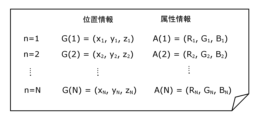
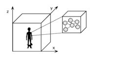
- Figure 2 is a diagram showing the structure of point cloud data.
- Figure 3 is a diagram showing an example of the structure of a data file in which information about point cloud data is described.
- Point cloud data includes data on multiple points.
- the data on each point includes location information (three-dimensional coordinates) and attribute information for that location information.
- a collection of multiple such points is called a point cloud.
- a point cloud can represent the three-dimensional shape of an object.
- Position information such as three-dimensional coordinates is sometimes called geometry.
- the data for each point may include attribute information of multiple attribute types.
- the attribute types are, for example, color or reflectance.
- One piece of attribute information may be associated with one piece of location information, or multiple pieces of attribute information with different attribute types may be associated with one piece of location information. Also, multiple pieces of attribute information of the same attribute type may be associated with one piece of location information.
- the data file configuration example shown in Figure 3 is an example where there is a one-to-one correspondence between position information and attribute information, and shows the position information and attribute information of N points that make up the point cloud data.
- the position information is, for example, information on the three axes x, y, and z.
- the attribute information is, for example, RGB color information.
- a typical example of a data file is a ply file.
- Figure 4 is a diagram showing the structure of three-dimensional mesh data.
- Figure 5 is a diagram showing an example of the structure of a data file in which information about the three-dimensional mesh data is described.
- Three-dimensional mesh data is a data format used in CG (Computer Graphics) that represents the three-dimensional shape of an object as a collection of multiple pieces of surface information. Each piece of surface information represents a polygon such as a triangle or a quadrangle. Three-dimensional mesh data is also called a polygon or polygon mesh.
- CG Computer Graphics
- the components are a three-dimensional point cloud, vertices that are multiple three-dimensional points of the three-dimensional point cloud, edges that connect two vertices at multiple three-dimensional points, and a collection of faces that are surrounded by multiple edges.
- a three-dimensional point cloud is a collection of points that include position information in three-dimensional space and attribute information that corresponds to that position information. Note that three-dimensional points may simply be referred to as points.
- a vertex may have attribute information such as color information, reflectance, and normal vector for a three-dimensional point.
- the relationship between the vertices that make up an edge or face may be indicated by information called connectivity.
- a vertex may be expressed as a position.
- the front and back of a face may be expressed by the direction of the normal vector for the three-dimensional point.
- a vertex may also have attribute information for the face.
- An example of the format of a mesh data file is an object file.
- a mesh data file such as that shown in Figure 5
- the position information G(1) to G(N) of the N vertices that make up the mesh and the vertex attribute information A(1) to A(N) are shown as vertex information.
- the vertex information does not have to include attribute information.
- the mesh data file in Figure 5 shows an example of three-dimensional mesh data having M pieces of attribute information A2.
- the number of vertices of a face is not limited to three, as long as the number of vertices is an integer equal to or greater than three. For example, if the face is a quadrangle, the number of vertices is four, and if the face is a polygon, the number of vertices is equal to the number of vertices that form the polygon.
- the attribute information A2 may be indicated in a file separate from the mesh data file, and may include pointer information thereto.
- the attribute information may be stored in a two-dimensional attribute map file, and the attribute map file name and two-dimensional coordinates in the attribute map may be indicated by the attribute information A2 of the mesh data file.
- the attribute information A2 may be included in the mesh data file, or may be indicated in a file separate from the mesh data file, and either method can be used to specify attribute information for a three-dimensional point.
- Figure 6 is a diagram to explain the three-dimensional model.
- a three-dimensional model is a model created based on two-dimensional or three-dimensional data.
- the three-dimensional model learning unit 1031 learns, for example, two-dimensional data (two-dimensional images) or three-dimensional data (point clouds or meshes) to generate a three-dimensional model, which is a network model in which three-dimensional shapes and attribute information corresponding to the three-dimensional shapes are learned using a Neural Network or the like.
- the three-dimensional model learning unit 1031 may generate a three-dimensional model by learning using NeRF (Neural Radiance Fields) based on a two-dimensional image.
- the three-dimensional model learning unit 1031 may generate a three-dimensional model after converting the two-dimensional image into three-dimensional data by performing photogrammetry using the two-dimensional image.
- the three-dimensional model may be generated using three-dimensional data acquired by a sensor (distance sensor).
- the three-dimensional model data is the elements that make up the three-dimensional model, and includes information indicating the structure of the network model, features, etc.
- the three-dimensional model data includes, for example, information about the components of a neural network.
- Information about the components includes, for example, multiple layers such as an input layer, intermediate layer, and output layer, nodes in each layer, weighting coefficients for the nodes, transformation functions for the nodes, etc.
- the three-dimensional model encoding unit 1032 may encode the three-dimensional model data and transmit the encoded three-dimensional model data.
- the three-dimensional model decoding unit 1033 receives the transmitted encoded three-dimensional model data and decodes the three-dimensional model based on the encoded three-dimensional model data.
- the rendering reconstruction unit 1034 reconstructs (generates) two-dimensional data (two-dimensional image) or three-dimensional data (point cloud or mesh) based on the decoded three-dimensional model.
- the rendering reconstruction unit 1034 acquires viewpoint position or line of sight vector information, generates rendered two-dimensional data (two-dimensional image) based on the three-dimensional model and the viewpoint position or line of sight vector, and outputs the two-dimensional data.
- the generated two-dimensional data indicates a three-dimensional object seen from the viewpoint position, or a two-dimensional image of the three-dimensional object seen from the line of sight indicated by the line of sight vector.
- the three-dimensional object is the three-dimensional data input to the three-dimensional model learning unit 1031 or the three-dimensional object of the subject that was the source of the three-dimensional data.
- Figure 7 is a diagram showing the types of three-dimensional data. As shown in Figure 7, three-dimensional data includes static objects and dynamic objects.
- a static object is three-dimensional data at any time (a certain moment in time).
- a dynamic object is three-dimensional data that changes over time.
- point cloud data at a certain moment in time will be referred to as a PCC frame, or frame.
- mesh data at a certain moment in time will be referred to as a mesh frame, or frame.
- the object may be three-dimensional data with a certain area restriction, such as ordinary video data, or it may be three-dimensional data with no area restriction, such as map information.
- sparse point cloud data sparse mesh data
- dense point cloud data dense point cloud data with various densities of points.
- Sensor information is acquired in various ways, such as distance sensors such as LIDAR or range finders, stereo cameras, or a combination of multiple monocular cameras.
- the three-dimensional data generation unit 1018 generates point cloud data based on the sensor information acquired by the sensor information acquisition unit 1017.
- the three-dimensional data generation unit 1018 generates position information (geometry information) as point cloud data, and adds attribute information for the position information to the position information.
- the three-dimensional data generating unit 1018 may process the point cloud data when generating position information or adding attribute information. For example, the three-dimensional data generating unit 1018 may reduce the amount of data by deleting point clouds with overlapping positions. The three-dimensional data generating unit 1018 may also convert the position information (such as by shifting the position, rotating, or normalizing), or process the point cloud data to generate mesh data. The three-dimensional data generating unit 1018 may also render the attribute information.
- the three-dimensional data generation system 1011 is included in the three-dimensional data encoding system 1001, but it may be provided independently outside the three-dimensional data encoding system 1001.
- the encoding unit 1013 generates encoded data by encoding the three-dimensional data based on a predefined encoding method.
- the encoding methods include G-PCC (an encoding method using position information), V-PCC (an encoding method using a video codec), Draco (a mesh encoding method), and V-DMC (a mesh encoding method).
- the encoding method is not limited to these methods, and may be, for example, a method of encoding a dynamic mesh, or another method that combines these methods.
- the decoding unit 1024 decodes the three-dimensional data by decoding the encoded data based on a predefined encoding method.
- the multiplexing unit 1014 generates multiplexed data by multiplexing the encoded data using an existing multiplexing method.
- the generated multiplexed data is transmitted or stored.
- the multiplexing unit 1014 multiplexes other media such as video, audio, subtitles, applications, files, or reference time information.
- the multiplexing unit 1014 may further multiplex attribute information related to sensor information or point cloud data.
- Multiplexing methods or file formats include ISOBMFF, MPEG-DASH, which is an ISOBMFF-based transmission method, MMT, MPEG-2 TS Systems, and RTP.
- the demultiplexing unit 1023 extracts the encoded data of the three-dimensional data, other media, time information, etc. from the multiplexed data.
- the input/output unit 1015 transmits the multiplexed data using a method suited to the transmission medium or storage medium, such as broadcasting or communication.
- the input/output unit 1015 may communicate with other devices via the Internet, or may communicate with a storage unit such as a cloud server.
- the communication protocol used may be http, ftp, TCP, or UDP.
- a PULL type communication method or a PUSH type communication method may be used.
- Either wired transmission or wireless transmission may be used.
- Ethernet registered trademark
- USB registered trademark
- RS-232C HDMI
- coaxial cable etc.
- wireless transmission wireless LAN, Wi-Fi (registered trademark), Bluetooth (registered trademark), millimeter waves, etc. are used.
- Broadcasting methods that are used include, for example, DVB-T2, DVB-S2, DVB-C2, ATSC3.0, and ISDB-S3.
- FIG. 8 is a diagram for explaining the process of encoding three-dimensional data.
- FIG. 9 is a diagram for explaining the process of decoding three-dimensional data.
- the data division unit 1041 divides the three-dimensional data into one or more three-dimensional spaces, and generates one or more divided three-dimensional data (i.e., one or more divided three-dimensional data).
- the encoding unit 1042 may encode one or more divided three-dimensional data to generate encoded data.
- the data division unit 1041 and the encoding unit 1042 may be included in a single encoding device as components of the single encoding device, or may be included in separate devices.
- Each of the one or more three-dimensional spaces may be referred to as a tile or a space.
- the three-dimensional space is, for example, a bounding box.
- the three-dimensional data contained in each of the divided three-dimensional spaces may be referred to as a slice.
- a slice is divided three-dimensional data, and includes any of a point cloud, a mesh, and a three-dimensional model having position information (Geometry) or attribute information (Attribute).
- Each of the multiple slices is encoded by the encoding unit 1042 for each component, and is output as encoded data.
- the encoded data includes the encoded multiple slices.
- the decoding unit 1051 decodes one or more pieces of divided three-dimensional data (one or more slices) based on the encoded data.
- the data combining unit 1052 combines the one or more pieces of divided three-dimensional data to restore (generate) three-dimensional data.
- the decoding unit 1051 and the data combining unit 1052 may be included in one decoding device as components of the decoding device, or may be included in separate devices. The one or more pieces of divided three-dimensional data decoded by the decoding unit 1051 do not need to be combined.
- the decoding unit 1051 may decode a portion of the one or more pieces of divided three-dimensional data based on a portion of the encoded data, and output the decoded portion of the divided three-dimensional data. In this case, the decoding device does not need to have the data combining unit 1052.
- Figure 10 is a two-dimensional schematic diagram of tiles and slices of three-dimensional data.
- the encoding device may encode using the dependency relationships between the multiple slices, or may encode without using the dependency relationships.
- the encoding device can encode each slice independently, and the processing time can be reduced by encoding multiple slices using parallel processing.
- the decoding device can decode each slice independently, and the processing time can be reduced by decoding multiple slices using parallel processing.
- the decoding device can reduce the amount of processing by partial decoding, which decodes some of the multiple slices.
- the encoding device When encoding using a dependency relationship, the encoding device signals an identifier indicating the dependency relationship and encodes the data in order starting with the dependent data. When multiple slices are encoded using a dependency relationship, the decoding device decodes the data in order starting with the dependent data based on the identifier.
- the three-dimensional data may be divided into any number of divisions and any division method may be used.
- the shape of an object may be determined and multiple three-dimensional points may be divided for each object.
- the three-dimensional data may also be divided based on the number of three-dimensional points contained in a slice. In other words, an upper limit on the number of three-dimensional points contained in one slice may be set.
- the three-dimensional data may also be divided based on whether or not it is contained in a three-dimensional space (tile information) using map information or location information. Multiple tile shapes may overlap.
- the server accumulates multiple pieces of three-dimensional data for the same space.
- the server accumulates, for example, point cloud data and mesh data for the same space.
- the server is an example of an encoding device.
- the terminal switches the three-dimensional data acquired from the server based on the purpose of the terminal, and presents the switched three-dimensional data.
- the terminal may be, for example, a terminal that analyzes three-dimensional data. In this case, the terminal may switch the three-dimensional data to be presented based on the purpose, such as analysis or presentation, or user operation.
- the terminal is an example of a decoding device.
- the terminal may transmit a user's selection result to a server, receive (download) three-dimensional data based on the selection result from the server, and present the received three-dimensional data.
- the three-dimensional data may or may not be encoded by the server.
- the terminal may receive the encoded three-dimensional data from the server, decode the three-dimensional data based on the received encoded three-dimensional data, and present the decoded three-dimensional data.
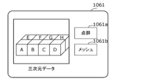
- FIG. 11 shows an example of a terminal presentation screen that can be switched in response to a user request.
- the terminal presentation screen 1061 may be switched in response to a user request.
- the terminal presentation screen includes a point cloud button 1061a and a mesh button 1061b as a UI for accepting user requests.
- the point cloud button 1061a is a button for accepting a request to present an encoded point cloud (encoded point cloud data).
- the mesh button 1061b is a button for accepting a request to present an encoded mesh (encoded mesh data).
- the terminal accepts the request to present the encoded point cloud and notifies (transmits) the request as a result of the selection of the presented data to the server.
- the terminal accepts the request to present the encoded mesh and notifies (transmits) the request as a result of the selection of the presented data to the server.
- presentation may be expressed as display.
- the server When the server receives a request as a selection result, it transmits three-dimensional data corresponding to the selection result to the terminal. If the received request is a request to present an encoded point cloud, the server transmits the encoded point cloud to the terminal. If the received request is a request to present an encoded mesh, the server transmits the encoded mesh to the terminal.
- Meshes are characterized by the small processing load required for presentation, making them suitable for presentation.
- point clouds are characterized by the high accuracy of the positional information of 3D models represented by 3D point clouds, making them suitable for measurement. For example, a user can select a mesh when wishing to observe a 3D model, or a point cloud when wishing to make measurements. By selecting the type of 3D data appropriate for the required application, the user can reduce presentation processing or use the data for accurate measurements.
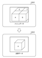
- FIG. 12 shows an example of a terminal presentation screen that is automatically switched in response to a user operation.
- the terminal performs a process of enlarging the three-dimensional data by accepting a user's operation.
- the terminal may present mesh data as in terminal presentation screen 1062, and at a magnification equal to or greater than the predetermined magnification, present point cloud data as in terminal presentation screen 1063.
- the terminal may present mesh data at a magnification smaller than the predetermined magnification, and when the mesh data is enlarged to the predetermined magnification in response to a user's operation and presented, download point cloud data from a server that corresponds to a portion of the three-dimensional data that is focused on (presented by enlarging), and decode and present the downloaded point cloud data.
- the type of three-dimensional data to be presented is switched in response to an operation to enlarge or reduce the three-dimensional data, but the type of three-dimensional data to be presented may be switched by other operations.
- the terminal may switch to and present point cloud data corresponding to the part of the mesh data selected by the tap.
- the terminal may present the point cloud data by superimposing it on the mesh data, or may switch the point cloud data from the mesh data and present it independently (i.e., without presenting the mesh data).
- the terminal may predict in advance before presentation at a predetermined magnification rate, download point cloud data corresponding to the enlarged part, and decode and present the downloaded point cloud data.
- the terminal may present the downloaded point cloud data as it is without spatial synchronization.
- the terminal may present the point cloud data by aligning it with the mesh data (or the coordinate system of the mesh data) based on synchronization information regarding spatial synchronization.
- the terminal may present the point cloud data without aligning it. Note that, although an example of spatially synchronizing point cloud data with mesh data has been described above, the terminal may also present mesh data in spatial synchronization with the point cloud data.
- the terminal downloads only the necessary point cloud data, and then decrypts and presents the downloaded point cloud data. This is expected to reduce the communication volume between the server and the terminal, reduce the processing load on the terminal, and reduce the latency of presentation time.
- mesh data has a small data size
- point cloud data has a large data size.
- the terminal can reduce the delay until initial presentation by first downloading the mesh data and presenting it initially.
- the terminal can reduce the processing load required for observing and processing 3D models.
- the terminal can improve visibility and make measurements easier.
- the three-dimensional data to be presented may be switched based on the communication network bandwidth.
- the terminal may present mesh data when the bandwidth is narrow and the network speed is slower than a predetermined speed, and present point cloud data when the network speed is equal to or faster than the predetermined speed.
- the three-dimensional data to be presented may also be switched depending on the capabilities of the terminal. For example, the three-dimensional data to be presented may be switched based on the processing performance of the terminal or the usage rate of the terminal's CPU.
- the terminal may switch from presenting point cloud data to presenting mesh data if the processing performance or CPU resources of the terminal are insufficient to process the point cloud data.
- presenting mesh data the terminal may switch from presenting mesh data to presenting point cloud data if it is determined that the processing performance or CPU resources of the terminal are sufficient to process the mesh data.
- the terminal may switch the type of 3D data presented, such as presenting the exterior of a building or map as mesh data, and presenting point cloud data when the data includes areas that require measurement, such as distortion, cracks, and warping of the building.
- the terminal can also switch the type of 3D data it presents, for example, presenting mesh data when it is desired to present the external appearance of spaces such as stadiums, halls, and factories, including lighting brightness, color, and atmosphere, and presenting point cloud data when it is desired to measure studio shapes, equipment layouts, and passageway clearances, etc.
- three-dimensional data with different resolutions may be displayed in a switched manner.
- the terminal may switch between presenting multiple point cloud data with different resolutions, multiple mesh data with different resolutions, and the three-dimensional model. For example, the terminal may present low-resolution mesh data when presenting three-dimensional data that is far from the viewpoint, and switch to high-resolution mesh data when the data is closer. This can improve the accuracy of the three-dimensional data display.
- the terminal may present mesh data until a specific movement or location is identified, and then switch to presenting point cloud data of the corresponding body part after the specific movement or location is identified, and use the point cloud data to measure the three-dimensional shape.
- the terminal may switch between three-dimensional models with different resolutions in video games, etc.
- the terminal may, for example, use high-resolution three-dimensional data to present three-dimensional data of important parts, and low-resolution three-dimensional data to present three-dimensional data of unimportant parts. This can improve overall processing performance.
- whether each three-dimensional model is important or not is determined, for example, by whether it is related to the action of the video game (in a shooting game, the player, target, gun, etc. are important), or whether it is related to the player's choices (in a purchasing scene, product information is important, etc.). Note that whether each three-dimensional model is important or not may be set in advance for each video game.
- the terminal may switch between terrain data with different resolutions. This allows more detailed terrain information to be displayed as needed.
- the terminal when displaying thumbnails on the web, the terminal may present low-resolution three-dimensional data, and when measuring or presenting in an application using the three-dimensional data selected on the thumbnail, high-resolution three-dimensional data may be used for measurement or presentation.
- the three-dimensional data when displaying on a two-dimensional display terminal, the three-dimensional data is presented as two-dimensional data when the three-dimensional object (subject) is viewed from a specific viewpoint in a specific direction.
- the three-dimensional data may be divided into camera information indicating a specific viewpoint and a specific direction, and two-dimensional data when the three-dimensional object is viewed from the specific viewpoint in the specific direction.
- the device When display is a priority, the device presents mesh data, which requires light processing, and when making measurements, replaces it with point cloud data suitable for the measurement, making it possible to realize applications that require light processing.
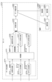
- Figure 13 is a block diagram showing an example of the functional configuration of the server and the terminal.
- the server 1070 includes a data generation unit 1071, a synchronization unit 1075, a point cloud coding unit 1076, a mesh coding unit 1077, a model coding unit 1078, a multiplexing unit 1079, and a data extraction unit 1080.
- the data generation unit 1071 generates three-dimensional data based on at least one of two-dimensional data and three-dimensional data.
- the generated three-dimensional data includes at least two of point cloud data, mesh data, and three-dimensional model data.
- the data generation unit 1071 has a point cloud generation unit 1072, a mesh generation unit 1073, and a model generation unit 1074.
- the data generation unit 1071 only needs to have at least two of the point cloud generation unit 1072, the mesh generation unit 1073, and the model generation unit 1074.
- the point cloud generation unit 1072 generates point cloud data based on at least one of two-dimensional data and three-dimensional data.
- the mesh generation unit 1073 generates mesh data based on at least one of two-dimensional data and three-dimensional data.
- the model generation unit 1074 generates three-dimensional model data by machine learning based on at least one of the two-dimensional data and three-dimensional data.
- the two-dimensional data input to the data generation unit 1071 may be a two-dimensional image acquired by a camera.
- the three-dimensional data input to the data generation unit 1071 may be point cloud data acquired by a sensor such as LiDAR of a space such as a construction site, a factory, or an office.
- the data generation unit 1071 may generate color information corresponding to each point included in the point cloud data of the three-dimensional data as attribute information using a two-dimensional image of the two-dimensional data.
- the three-dimensional data generated by the data generation unit 1071 may be divided into any space.
- the point cloud data, mesh data, and three-dimensional model data may each be divided into any space.
- the synchronization unit 1075 synchronizes the spatial positions of the point cloud data, mesh data, and three-dimensional model data generated by the data generation unit 1071 or the time of each data (playback time, decode time, acquisition time, etc.).
- the time of each data is the playback time, decode time, acquisition time, etc.
- the synchronization unit 1075 may generate synchronization information for synchronization without synchronizing the point cloud data, mesh data, and three-dimensional model data.
- the synchronization unit 1075 may perform a process of synchronizing at least two types of three-dimensional data out of the point cloud data, mesh data, and three-dimensional model data generated by the data generation unit 1071, or generate synchronization information (synchronization signal) for synchronization, and may not perform a process (synchronization process) for synchronizing three types of three-dimensional data.
- the point cloud encoding unit 1076 encodes the point cloud data after the synchronization process is performed by the synchronization unit 1075. Note that the point cloud encoding unit 1076 does not have to encode the point cloud data.
- the point cloud data may be encoded in advance, or may be encoded in response to a request from the terminal 1090.
- the mesh encoding unit 1077 encodes the mesh data after the synchronization process is performed by the synchronization unit 1075.
- the model encoding unit 1078 encodes the three-dimensional model data after the synchronization process is performed by the synchronization unit 1075.
- the multiplexing unit 1079 multiplexes the encoded point cloud data (encoded point cloud), the encoded mesh data (encoded mesh data), the encoded three-dimensional model data, and the synchronization information using a predetermined format or a predetermined multiplexing method. Note that multiplexing by the multiplexing unit 1079 does not have to be performed. In this case, the server 1070 does not have to be equipped with the multiplexing unit 1079.
- the data extraction unit 1080 extracts a portion of the multiplexed three-dimensional data in response to a request from the terminal 1090, and transmits the extracted portion of the three-dimensional data to the terminal 1090.
- data extraction by the data extraction unit 1080 may not be performed.
- the server 1070 may not include the data extraction unit 1080.
- the server 1070 may transmit to the terminal 1090 the three-dimensional data multiplexed by the multiplexing unit 1079.
- the server 1070 may transmit to the terminal 1090 the coded point cloud data (coded point cloud), the coded mesh data (coded mesh), the coded three-dimensional model data (coded three-dimensional model), and the synchronization information, or may transmit to the terminal 1090 a bit stream including the coded point cloud data (coded point cloud), the coded mesh data (coded mesh), the coded three-dimensional model data (coded three-dimensional model), and the synchronization information.
- the terminal 1090 includes a control unit 1091, a decoding unit 1092, and a presentation unit 1093.
- the control unit 1091 transmits a request for a portion of the three-dimensional data to be presented to the server 1070.
- the control unit 1091 may also accept an operation by the user to identify the portion of the three-dimensional data.
- the decoding unit 1092 decodes a portion of the three-dimensional data based on the bit stream (encoded data) obtained from the server 1070.
- the presentation unit 1093 renders and presents a portion of the decoded three-dimensional data.
- the data generation unit 1071 in FIG. 13 may be realized by the data generation unit 1110 shown in FIG. 14.
- FIG. 14 is a block diagram showing another example of the data generation unit of the server.
- the data generation unit 1110 includes a point cloud generation unit 1111, a mesh generation unit 1112, and a model generation unit 1113.
- the point cloud generation unit 1111 has the same functions as the point cloud generation unit 1072.
- the point cloud generation unit 1111 acquires point cloud data obtained from the point cloud sensor 1101 and a two-dimensional image obtained from the camera 1102, and generates point cloud data based on the point cloud data and the two-dimensional image.
- the point cloud data generated by the point cloud generation unit 1111 includes position information of each point and attribute information corresponding to each point indicated by the position information, and includes attribute information (such as color information) extracted from the two-dimensional image.
- the mesh generation unit 1112 generates mesh data based on the point cloud data generated by the point cloud generation unit 1111.
- the model generation unit 1113 has the same functions as the model generation unit 1074.
- the model generation unit 1113 acquires point cloud data obtained from the point cloud sensor 1101 and two-dimensional images obtained from the camera 1102, and generates three-dimensional model data by performing machine learning based on the point cloud data and the two-dimensional images.
- the point cloud data, mesh data, and three-dimensional model data may be data generated independently of each other, as described in FIG. 13.
- the mesh data may be generated from the point cloud data, as described in FIG. 14. Note that the point cloud data may be generated from the mesh data.
- Meshes may be generated from point clouds and vice versa.
- the point cloud data, mesh data, and three-dimensional model data may be generated by the server 1070, or may be generated by a sensor or a terminal 1090 equipped with a sensor.
- the sensor is, for example, a point cloud sensor 1101 and a camera 1102.
- Figures 15 and 16 are diagrams for explaining the process of synchronizing the coordinate systems.
- the origin position (origin coordinates) of the local coordinate system handled by the system may differ from the actual coordinates due to differences in the system or coordinate system used.
- the origin position is the same for the mesh data and the point cloud data, but if the mesh data and the point cloud data are generated in different systems, the origin positions may be different for the mesh data and the point cloud data.
- the origin coordinates of the mesh data coordinate system and the origin coordinates of the point cloud data coordinate system are both, for example, (x1, y1, z1) in world coordinates, and the mesh data coordinate system and the point cloud data coordinate system are the same. Note that if these origin coordinates are not the same, they may be corrected to be the same.
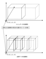
- FIG. 15 shows a case where the three-dimensional spatial region for dividing the mesh data and the three-dimensional spatial region for dividing the point cloud data are the same. Specifically, the number of three-dimensional spatial regions, the size of the three-dimensional spatial regions, and the positions of the three-dimensional spatial regions are the same between the multiple three-dimensional spatial regions in the mesh data coordinate system and the multiple three-dimensional spatial regions in the point cloud coordinate system.
- the positions of the origin of the bounding box that represents the three-dimensional space (black triangle mark) and the maximum value point of the bounding box (black square mark) are the same in the coordinate system of the mesh data and the coordinate system of the point cloud data.
- this bounding box is the same in the coordinate system of the mesh data and the coordinate system of the point cloud data.
- the number of three-dimensional spatial regions, the size of the three-dimensional spatial regions, and the positions of the three-dimensional spatial regions do not have to be completely identical between the multiple three-dimensional spatial regions in the mesh data coordinate system and the multiple three-dimensional spatial regions in the point cloud coordinate system.
- the three-dimensional spatial regions in the mesh data coordinate system may be divided into larger regions, and the three-dimensional spatial regions in the point cloud data coordinate system may be regions into which the three-dimensional spatial regions in the mesh data coordinate system are further divided.
- the unit formed by combining multiple three-dimensional spatial regions in the point cloud data coordinate system is identical to the three-dimensional spatial region in the mesh data coordinate system.
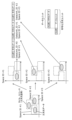
- Figure 17 is a diagram for explaining the relationship between three-dimensional space and encoded data.
- the three-dimensional data includes, for example, point cloud data, mesh data, and three-dimensional models.
- the encoding device encodes each of the three divided three-dimensional data, attaches a header, and creates a data unit.
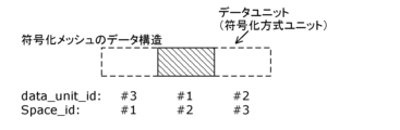
- the header signals (assigns) the identifier of the space to which the encoded data of the data unit belongs (Space_ID), and the identifier of the data unit (DataUnit_ID).
- the data unit is further given a header that includes the data unit's identifier or length information of the data unit, and is then unitized to generate an encoding method unit.
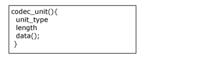
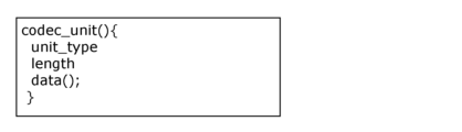
- Fig. 18 is a diagram showing an example of the syntax of the coding method unit.
- Fig. 19 is a diagram showing an example of the syntax of the coding point group.
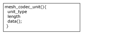
- Fig. 20 is a diagram showing an example of the syntax of the coding mesh.
- Fig. 21 is a diagram showing an example of the syntax of the coding 3D model.
- unit_type indicates the type of data unit stored in the encoding method unit. This specifies the type of data unit stored in the encoding method unit.
- Length indicates the length of the data unit.
- data() indicates the body of the data unit.
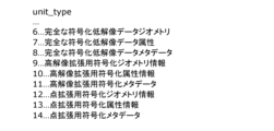
- unit_type when unit_type indicates 0, it indicates that the data unit is position information (geometry) of the encoded point group. When unit_type indicates 1, it indicates that the data unit is attribute information of the encoded point group. When unit_type indicates 2, it indicates that the data unit is metadata of the encoded point group.
- unit_type when unit_type indicates 0, it indicates that the data unit is position information (geometry) of the encoded mesh. When unit_type indicates 1, it indicates that the data unit is attribute information of the encoded mesh. When unit_type indicates 2, it indicates that the data unit is metadata of the encoded mesh.
- unit_type when unit_type indicates 0, it indicates that the data unit is element 1 of the encoded 3D model. When unit_type indicates 1, it indicates that the data unit is element 2 of the encoded 3D model. When unit_type indicates 2, it indicates that the data unit is metadata of the encoded 3D model.
- syntax shown in Figures 19 to 21 is an example and is not limited to the above configuration. These syntaxes may use a partial configuration of the syntax, or a type (category) not described above may be used, or the order of the syntax components may be changed.
- the syntax of the encoding method unit may have an encoding method unit configuration common to multiple encoding methods as shown in Figure 18, and may indicate the unit_type, length, and data() shown in Figures 19 to 21.
- a header may be added to the encoding method unit to indicate the type of the encoding method unit.
- the encoding unit types include, for example, point_cloud_codec_unit, which indicates point cloud data, mesh_codec_unit, which indicates mesh data, and model_codec_unit, which indicates three-dimensional model data. This makes it possible to handle multiple encoding methods in an integrated manner.
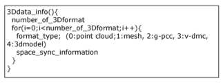
- FIG. 22 shows an example of the syntax of three-dimensional data information.
- the syntax when multiple encoding methods are stored in one format, the number of three-dimensional data included in the format (number_of_3Dformat) and the type of three-dimensional data (format_type) are indicated, and data of each format may be stored. This makes it possible to handle multiple encoding methods or three-dimensional data in an integrated manner, and also makes it possible to identify multiple encoding methods or three-dimensional data.
- 3Ddata_info indicates the format structure information for storing multiple three-dimensional data.
- number_of_3Dformat indicates the number of 3D formats used.
- format_type indicates the type of format of the three-dimensional data to be stored. For example, the number of format_type and the format corresponding to that number may be defined as follows: When format_type indicates 0, it indicates that the format of the three-dimensional data to be stored is point cloud data (point cloud). When format_type indicates 1, it indicates that the format of the three-dimensional data to be stored is mesh data (mesh). When format_type indicates 2, it indicates that the format of the three-dimensional data to be stored is G-PCC data (g-pcc). When format_type indicates 3, it indicates that the format of the three-dimensional data to be stored is V-DMC data (v-dmc). When format_type indicates 4, it indicates that the format of the three-dimensional data to be stored is three-dimensional model data (3Dmodel).
- FIG. 23 is a diagram for explaining the data structure of an encoded point group.
- FIG. 24 is a diagram for explaining the data structure of an encoded mesh.
- FIG. 25 is a diagram for explaining the data structure of an encoded three-dimensional model.
- the encoding device divides each of the multiple types of three-dimensional data into multiple pieces of three-dimensional data for each of the multiple spatial regions, encodes each of the multiple pieces of divided three-dimensional data (i.e., the multiple divided three-dimensional data), and generates encoded data.
- Each encoded data is given a header and contains at least one of the data_unit_id and space_id.
- data_unit_id is an identifier that identifies a data unit within the encoded data, and is unique within the encoded data. Furthermore, space_id indicates identification information for a spatial region. If data_unit_id or space_id is common to multiple pieces of three-dimensional data, the same value is indicated in the multiple pieces of three-dimensional data.
- the data, headers, and other data may be included in a bitstream structure such as a data unit or encoding method, or may be stored in a specified file format such as each ISOBMFF box.
- Fig. 26 is a diagram showing an example of multiple three-dimensional spaces in two dimensions.
- Fig. 27 is a diagram showing an example of a bounding box.
- Fig. 28 is a diagram showing an example of the syntax of three-dimensional space information.
- 3Dspace_info is information that indicates the divided three-dimensional space. 3Dspace_info can be used for partial decoding.
- number_of_space indicates the number of divided three-dimensional spaces.
- space_id indicates the identifier of the divided three-dimensional space.
- the three-dimensional spatial information includes bounding box information for defining the bounding box shown in FIG. 27.
- Bounding box information includes bounding_box_xyz and bounding_box_whd.
- bounding_box_xyz indicates the coordinates of the reference point of the bounding box. In the example of Figure 27, it is expressed as x, y, and z coordinate values (x0, y0, z0).
- bounding_box_whd indicates the size of the bounding box. In the example of Figure 27, it is expressed as width w, height h, and depth d (w0, h0, d0).
- the three-dimensional spatial information may also include an identifier of a data unit for each piece of encoded data. However, the three-dimensional spatial information does not have to include the identifier. In other words, the identifier does not have to be signaled.
- pointcloud_id indicates the identifier of the data unit of the encoded point cloud for the space corresponding to space_id.
- mesh_id indicates the identifier of the data unit of the spatial coding mesh corresponding to space_id.
- model_id indicates the identifier of a data unit of the encoded 3D model of the space corresponding to space_id.
- the identifier of the data unit for each piece of encoded data may be stored in the information indicating each space of the three-dimensional spatial information. This allows the three-dimensional spatial information to be associated with the divided three-dimensional encoded data.
- the three-dimensional spatial information may be associated with an identifier for the data unit for each encoded data by the space_id. In this case, the identifier for the data unit for each encoded data does not need to be stored.
- the division method, the origin of each divided space, and the bounding box size may be the same for the mesh data and the point cloud data, so that the three-dimensional spatial information of the point cloud data and the three-dimensional spatial information of the mesh data can be made common. Also, the same three-dimensional spatial information may be used for the point cloud data and the mesh data. In this way, the three-dimensional spatial information may be common or the same three-dimensional spatial information may be used between multiple different types of three-dimensional data. By commonizing the three-dimensional spatial information, it becomes easy to switch between different types of three-dimensional data (for example, switching the presentation or switching the transmission).
- three-dimensional spatial information does not need to be provided for each piece of three-dimensional data, and one piece of three-dimensional spatial information can be used for each piece of three-dimensional data, so that the amount of data of the three-dimensional spatial information can be reduced.
- the three-dimensional spatial information of the three-dimensional model may be synchronized with other types of three-dimensional data, or may be shared with the three-dimensional spatial information of other types of three-dimensional data.
- Fig. 29 is a flowchart showing an example of partial decoding.
- Fig. 30 is a diagram showing an example of a three-dimensional spatial region that is the subject of partial decoding.
- Fig. 31 is a diagram showing an example of the data structure of a group of encoded points to be partially decoded.
- Fig. 32 is a diagram showing an example of the data structure of an encoded mesh to be partially decoded.
- Fig. 33 is a diagram showing an example of the data structure of an encoded three-dimensional model to be partially decoded.
- the decoding device first determines the three-dimensional spatial region to be subjected to partial decoding (S1001).
- the decoding device uses the three-dimensional space information (3Dspace_info) to identify an area that overlaps with the target three-dimensional space area from the bounding box information of multiple three-dimensional space areas, and obtains the space_id corresponding to the identified area (S1002).
- 3Dspace_info three-dimensional space information
- the decoding device obtains and decodes the data unit having the obtained space_id from the encoded data (S1003). As a result, the decoding device performs partial decoding, which decodes a portion of the three-dimensional data. In partial decoding, the decoding device decodes only a portion of the three-dimensional data, without decoding all of the three-dimensional data.
- the space_id of the three-dimensional space to be obtained is determined to be #2 from the three-dimensional space information.
- the decoding device may also obtain a data unit ID instead of a space_id from the three-dimensional spatial information, and obtain and partially decode a data unit having the obtained data unit ID.
- Figure 34 is a diagram showing an example of a coordinate system of different types of three-dimensional data where spatial synchronization is not achieved.
- Figure 35 is a diagram showing an example of the syntax of three-dimensional data information.
- Figure 36 is a diagram showing an example of the syntax of three-dimensional space information.
- the encoding device may align these origin coordinates by calculating and correcting the relative coordinate values (x1-x2, y1-y2, z1-z2).
- the encoding device may notify (transmit) the calculated relative coordinate values to the decoding device (terminal) as synchronization information.
- the synchronization information may be indicated by the relative position of the point cloud data position (origin) relative to the mesh data position (origin), or may be indicated by the relative position of the mesh data position relative to the point cloud data position.
- the synchronization information may be indicated by the relative position of the positions (origins) of different types of three-dimensional data. Note that when there are three or more types of three-dimensional data, the relative position is calculated based on any one type of three-dimensional data.
- the three-dimensional data information may include space_sync_information, which indicates synchronization information, as shown in FIG. 35.
- the space_sync_information indicates synchronization information for three-dimensional space, and indicates, for example, the amount of deviation in three-dimensional space (the difference between the reference coordinates and the current coordinates, i.e., a relative value).
- synchronization information (space_sync_information) may be stored for each of the multiple format information.
- the data format that is the basis for synchronization may be placed at the beginning of the loop, and synchronization information (relative position information) from the beginning format may be stored from the second loop onwards.
- the three-dimensional space information may also include space_sync_information, which indicates synchronization information, as shown in FIG. 36. If the spatial position is shifted for each three-dimensional space, the synchronization information may be stored in a loop for each three-dimensional space.
- FIG. 37 shows an example of the functional configuration of a terminal.
- the terminal 1120 includes a decoding unit 1121 and a synchronous presentation unit 1122.
- the decoding unit 1121 decodes the synchronization information based on the three-dimensional data information or the three-dimensional space information.
- the synchronization presentation unit 1122 aligns and presents the three-dimensional data based on the synchronization information.
- Figure 38 is a flowchart showing an example of spatial synchronization processing.
- the system including the encoding device (server) and the decoding device (terminal) determines whether spatial synchronization is required between the point cloud data and the mesh data (S1011).
- step S1012 If the system determines that spatial synchronization is necessary (Yes in S1011), it executes step S1012; if the system determines that spatial synchronization is not necessary (No in S1011), it executes step S1013.
- step S1012 the system determines whether or not spatial synchronization has been achieved between the point cloud data and the mesh data (S1012).
- step S1014 If the system determines that spatial synchronization has been achieved (Yes in S1012), it executes step S1014, and if it determines that spatial synchronization has not been achieved (No in S1012), it executes step S1015.
- step S1013 the system presents the point cloud data and mesh data without spatial synchronization (S1013).
- step S1014 the system presents the point cloud data and mesh data in spatial synchronization based on the synchronization information (S1014).
- step S1015 the system presents the point cloud data and mesh data as is (S1015).
- steps S1011 to S1012 may be performed by an encoding device or a decoding device.
- the steps S1013 to S1015 may be performed by a decoding device.
- Whether or not spatial synchronization is required may be switched depending on the application or use. For example, when using three-dimensional data for measurement purposes, accurate positioning is required, so it may be determined that spatial synchronization is required.
- a level of alignment may be specified, in which case the system (encoding device or decoding device) may change the accuracy of synchronization based on the level of alignment.
- time synchronization may be performed to synchronize the presentation time, the decoding time, or the acquisition time. At least one of spatial synchronization and time synchronization may be performed.
- parameters such as the color matrix, color bit rate, and HDR may be set to the same.
- attribute information may be synchronized between multiple 3D data.
- switching of three-dimensional data has been described using different types of three-dimensional data such as point cloud data and mesh data as an example, but the multiple three-dimensional data to be switched is not limited to different types of three-dimensional data.
- the multiple three-dimensional data may be, for example, three-dimensional data with different resolutions, multiple point cloud data with different numbers of points, or multiple mesh data with different numbers of points or faces.
- the multiple three-dimensional data to be switched may be three or more pieces of three-dimensional data.
- the multiple pieces of three-dimensional data to be switched may be multiple pieces of point cloud data acquired at different times.
- the multiple pieces of three-dimensional data to be switched may include point cloud data before construction, point cloud data after construction, point cloud data 10 years later, modeled mesh data, etc., at a construction site.
- three-dimensional model data such as NeRF may be used.
- Three-dimensional model data is a model for presenting three-dimensional data, and may or may not be encoded. Multiple three-dimensional model data for the same space may be switched, or multiple three-dimensional model data may be switched.
- the spatial synchronization method described above can be used.
- by adding an identifier for three-dimensional model data to a data format that handles point cloud data and mesh data in an integrated manner it becomes possible to handle three-dimensional data and three-dimensional model data in an integrated manner.
- the spatial information oil, bounding box, division method, etc.
- the three-dimensional data to be processed may be switched in the following order: mesh data lower than the first resolution, mesh data higher than the first resolution, point cloud data lower than the second resolution, and point cloud data higher than the second resolution.
- the server may store data in a state in which multiple three-dimensional models have been encoded in advance, and extract the three-dimensional data corresponding to the request based on a request from the terminal.
- the server may encode the three-dimensional data corresponding to the request at the timing when the request is made from the terminal.
- the terminal may request the three-dimensional data to be processed in advance, and download the requested three-dimensional data from the server. This can reduce the time it takes for the terminal to present the data.
- the terminal can present divided data corresponding to the avatar's torso as a mesh and divided data corresponding to the face as a point cloud, enabling a more accurate presentation.
- point cloud data, mesh data, and three-dimensional model data have been given as examples of three-dimensional data representing a three-dimensional object, but this is not limiting.
- a three-dimensional object may be represented by multiple sets, each of which includes line-of-sight information indicating a line of sight and a two-dimensional image of the three-dimensional object as viewed from that line of sight.
- data including the multiple sets may be treated as a type of three-dimensional data.
- the three-dimensional data may be data in another format, such as Gaussian splatting data.
- FIG. 39 is a diagram showing an example of the configuration of a decoding device.
- FIG. 40 is a flowchart showing an example of a decoding method using the decoding device.
- the decoding device 1130 includes a circuit 1131 and a memory 1132 connected to the circuit 1131.
- Circuit 1131 performs the following operations:
- the circuit 1131 acquires encoded data including first data representing a three-dimensional object, encoding method information (format) indicating one of the encoding methods including the second data representing the three-dimensional object, and identification information indicating the three-dimensional space including the three-dimensional object (S1021).
- the circuit 1131 decodes the first data and the second data corresponding to the three-dimensional space based on the encoded data (S1022).
- the circuit 1131 renders the first data to generate first presentation data for presentation (S1023).
- the circuit 1131 renders the second data to generate second presentation data for presentation (S1024).
- the circuit 1131 switches from the generated second presentation data to the first presentation data and presents it (S1025).
- the first presentation data and the second presentation data are, for example, two-dimensional data or three-dimensional data generated by the rendering reconstruction unit 1034.
- the first presentation data and the second presentation data are generated based on the first data and the second data corresponding to the three-dimensional space, and the second presentation data is switched to the first presentation data for presentation, so that the presentation can be performed without causing any spatial misalignment when switching between the two data representing the three-dimensional object. Therefore, the first presentation data and the second presentation data can be presented appropriately.
- the first data is point cloud data representing the three-dimensional object.
- the second presentation data is switched to the first presentation data based on the point cloud data, so that the two pieces of data representing the three-dimensional object can be switched and presented without causing any spatial misalignment.
- the second data is mesh data representing the three-dimensional object.
- the second presentation data based on mesh data is switched to the first presentation data, so that the two pieces of data representing the three-dimensional object can be switched and presented without causing any spatial misalignment.
- the second data is three-dimensional model data representing the three-dimensional object.
- the three-dimensional model data represents a machine learning model obtained by machine learning a gaze and a plurality of sets of two-dimensional images.
- the second presentation data based on the three-dimensional model data is switched to the first presentation data, so that the two pieces of data representing the three-dimensional object can be switched and presented without causing any spatial misalignment.
- the second data is a two-dimensional image of the three-dimensional object when viewed from a specific viewing direction.
- the second presentation data based on a two-dimensional image is switched to the first presentation data, so that the two pieces of data representing a three-dimensional object can be switched and presented without causing any spatial misalignment.
- the circuit further receives a presentation data switching request from the user.
- the circuit switches from the second presentation data to the first presentation data in response to the switching request.
- the circuit further receives an operation from a user to change the mode of presentation.
- the circuit changes the mode of presentation in response to the operation, and switches from the second presentation data to the first presentation data in response to the change.
- the circuit acquires the encoded data from an encoding device via a communication network.
- the circuit switches from the second presentation data to the first presentation data in accordance with the bandwidth of the communication network.
- switching can be performed according to the bandwidth of the communication network; for example, when the bandwidth of the communication network changes from less than a specified bandwidth to equal to or greater than the specified bandwidth, the second presentation data can be switched to the first presentation data for presentation.
- the circuit switches from the second presentation data to the first presentation data in the presentation depending on the available capabilities of the circuit.
- switching can be performed according to the capacity of the available circuit. For example, when the capacity of the available circuit changes from less than a predetermined capacity to equal to or greater than the predetermined capacity, the second presentation data can be switched to the first presentation data for presentation.
- the encoded data includes synchronization information for synchronizing a coordinate system of the first data and a coordinate system of the second data.
- the circuit presents the first presentation data and the second presentation data based on the synchronization information.
- the first presentation data and the second presentation data can be switched to the first presentation data after the coordinate systems of the data are aligned. This makes it possible to switch and present two pieces of data representing a three-dimensional object in a way that minimizes spatial misalignment.
- the circuit further determines whether or not to synchronize the coordinate system of the first data with the coordinate system of the second data. If the circuit determines that the coordinate system of the first data is to be synchronized with the coordinate system of the second data, the circuit presents the first presentation data and the second presentation data based on the synchronization information during the presentation.
- synchronization processing can be performed when necessary, and can be skipped when it is not necessary. This has the potential to reduce the processing load.
- the first data and the second data each have a common configuration.
- the amount of encoded data can be reduced, and communication capacity can be reduced.
- the encoded data includes spatial information for identifying the three-dimensional space in which the three-dimensional object is included.
- the circuit further obtains a target area indicating a partial area of the three-dimensional space.
- the circuit identifies first duplicate data that is a part of the first data and that overlaps with the target area based on the spatial information. In the decoding, the circuit decodes the identified first duplicate data.
- the amount of data to be acquired can be reduced by acquiring only the first duplicate data. This makes it possible to reduce communication capacity. Also, for example, it is possible to decrypt only the first duplicate data. This makes it possible to reduce processing load.
- the circuit 1131 may also operate according to the decoding method shown in the flowchart of FIG. 41.
- FIG. 41 is a flowchart showing another example of a decoding method performed by a decoding device.
- the circuit 1131 decodes encoding method information that represents the three-dimensional object and indicates a second encoding method that is different from the first encoding method of the first data (S1031).
- the circuit 1131 decodes second data in the second encoding method indicated by the encoding method information (S1032).
- the second data is used to generate second presentation data for presentation.
- the second data of the second encoding method indicated by the encoding method information obtained by decoding is decoded, so that the second data can be obtained for generating appropriate second presentation data for presentation.
- FIG. 42 is a diagram showing an example of the configuration of an encoding device.
- FIG. 43 is a flowchart showing an example of an encoding method performed by the encoding device.
- the encoding device 1140 includes a circuit 1141 and a memory 1142 connected to the circuit 1141.
- Circuit 1141 performs the following operations:
- the circuit 1141 generates encoding method information that represents the three-dimensional object and indicates a second encoding method different from the first encoding method of the first data (S1041).
- the circuit 1141 generates second data in the second encoding method indicated by the encoding method information (S1042).
- the circuit 1141 generates a bitstream that includes the encoding method information and the second data (S1043).
- the second data is used to generate second presentation data for presentation.
- bitstream including the encoding method information and the second data is generated, and a decoding device that acquires the bitstream can obtain the second data for generating second presentation data for appropriate presentation.
- Embodiment 2 In this embodiment, a method for switching three-dimensional data, three-dimensional data formats, and encoding methods depending on the use case of an application that handles three-dimensional data including, for example, point cloud data, mesh data, and three-dimensional model data, is described.
- the decoding device may decode the desired type of three-dimensional data from the encoded data.
- the three-dimensional data of the desired resolution may be extracted from the encoded data and decoded.
- FIG. 44 is a diagram explaining partial decoding, which decodes a portion of three-dimensional data, in embodiment 2.
- the control unit 1202 specifies a portion of the three-dimensional data to be decoded.
- the partial decoding unit 1201 decodes a portion of the three-dimensional data specified by the control unit 1202. For example, the partial decoding unit 1201 acquires three-dimensional data from an encoding device and decodes a portion of the acquired three-dimensional data.
- FIG. 45 is a diagram illustrating an example of extracting and decoding a portion of three-dimensional data in embodiment 2.
- the control unit 1212 specifies the three-dimensional data to be extracted from the three-dimensional data.
- the data extraction unit 1211 extracts a portion of the three-dimensional data specified by the control unit 1212. For example, the data extraction unit 1211 extracts a portion of the three-dimensional data from the three-dimensional data, and transmits the extracted portion of the three-dimensional data to, for example, a decoding device.
- the encoded data may have a hierarchical structure. Also, hierarchical data indicating the hierarchical structure may be output.
- switching may be performed using two or more three-dimensional data of point cloud data, mesh data, and three-dimensional model data.
- FIG. 46 is a block diagram showing an example of the functional configuration of the server and the terminal in the second embodiment.
- the server 1220 is, for example, an encoding system that encodes three-dimensional data
- the terminal 1230 is a decoding system that decodes and generates the three-dimensional data.
- the server 1220 includes a point cloud generation unit 1221, a mesh generation unit 1222, a point cloud encoding unit 1223, and a multiplexing unit 1224.
- the point cloud generator 1221 generates point cloud data based on at least one of two-dimensional data and three-dimensional data.
- the mesh generation unit 1222 generates mesh data based on the point cloud data generated by the point cloud generation unit 1221.
- the point cloud encoding unit 1223 encodes three-dimensional data including the point cloud data generated by the point cloud generation unit 1221 and the mesh data generated by the mesh generation unit 1222.
- the multiplexing unit 1224 multiplexes the encoded three-dimensional data using a predetermined format or a predetermined multiplexing method. Note that multiplexing by the multiplexing unit 1224 does not have to be performed. In this case, the server 1220 does not have to be equipped with the multiplexing unit 1224.
- the multiplexed encoded data is transmitted (sent) to the terminal 1230.
- the terminal 1230 includes a control unit (application execution unit) 1231, a decryption unit 1232, and a presentation unit 1233.
- control unit application execution unit
- decryption unit 1232
- presentation unit 1233 presentation unit
- the control unit 1231 specifies a portion of the three-dimensional data to be decoded by the decoding unit 1232.
- the specified portion of the three-dimensional data is, for example, the type (format) of the three-dimensional data.
- the control unit 1231 specifies whether to decode point cloud data or mesh data.
- the control unit 1231 may specify the resolution of the three-dimensional data.
- the decoding unit 1232 decodes a portion of the three-dimensional data specified by the control unit 1231 from the encoded data received from the server 1220. If the control unit 1231 specifies that the decoding of point cloud data should be performed, the decoding unit 1232 decodes the point cloud data, and if the control unit 1231 specifies that the decoding of mesh data should be performed, the decoding unit 1232 decodes the mesh data. Alternatively, the decoding unit 1232 decodes three-dimensional data at a specified resolution.
- the presentation unit 1233 presents a portion of the three-dimensional data decoded by the decoding unit 1232. If point cloud data has been decoded by the decoding unit 1232, the presentation unit 1233 presents the point cloud data, and if mesh data has been decoded by the decoding unit 1232, the presentation unit 1233 presents the mesh data. Alternatively, the decoding unit 1232 presents three-dimensional data at a specified resolution.
- the point cloud data, mesh data, and three-dimensional model data are data with different resolutions, different display appearances, and different granularity.
- Three-dimensional data that includes at least two of the point cloud data, mesh data, and three-dimensional model data can also be said to be hierarchical data.
- FIG. 47 is a flowchart showing an example of processing by a terminal in embodiment 2.
- the control unit 1231 determines the format of the three-dimensional data to be used based on a predetermined process (S1201).
- the control unit 1231 instructs (specifies) the format of the three-dimensional data to be output (presented) to the decoding unit 1232 (S1202).
- the decoding unit 1232 decodes the three-dimensional data in the specified format using a predetermined method and outputs it (S1203).
- the presentation unit 1233 uses the three-dimensional data in the format specified by a predetermined method in an application (S1204). For example, the presentation unit presents the three-dimensional data.
- Trisoap method which is an example of a method for encoding position information using an encoding device.
- the Trithorpe method is a method for encoding the position information of point cloud data in the G-PCC encoding method, and is a lossy compression method.
- the original point cloud to be processed is replaced with a set of triangles, and the point cloud is approximated on the plane.
- the original point cloud is replaced with vertex information within a node, and a set of triangles is generated by connecting the vertices.
- the vertex information used to generate the triangles is stored in the bitstream and sent to the decoding device.
- Figure 48 is a diagram showing an example of an original point cloud in embodiment 2.
- the point cloud 1242 of the target object is contained in the target space 1241 and includes multiple points 1243.
- the encoding device divides the original point cloud into an octree to a predetermined depth.
- the target space is divided into eight nodes (subspaces), and 8-bit information (occupancy code) is generated indicating whether or not a point cloud is included in each node.
- the node that includes a point cloud is further divided into eight nodes, and 8-bit information is generated indicating whether or not a point cloud is included in each of the eight nodes. This process is repeated up to a predetermined hierarchy.
- octree division is repeated until, for example, the number of points contained in the node is reduced to one or a threshold value or less.
- octree division is performed up to an intermediate level, but not to the levels below that level. Such an octree up to an intermediate level is called a pruned octree.
- FIG. 49 is a diagram showing an example of a pruned octree in embodiment 2. As shown in FIG. 49, a point cloud 1242 is divided into multiple leaf nodes 1244 (nodes at the lowest level) of the pruned octree.
- the encoding device performs the following process on each of the leaf nodes 1244 of the pruned octree.
- the leaf node is also referred to simply as the node.
- the encoding device generates a vertex on the edge as a representative point of the point group close to the edge of the node. This vertex is called an edge vertex. For example, an edge vertex is generated for each of multiple edges (e.g., four parallel sides).
- FIG. 50 is an example of a two-dimensional display of a leaf node 1244 in the second embodiment, and is a diagram showing, for example, an xy plane as viewed from the z direction shown in FIG. 50. As shown in FIG. 50, an edge vertex 1252 is generated on the edge based on the adjacent points of the edge among the multiple points 1251 in the leaf node 1244.
- edge vertex 1252 is generated at the weighted average position of points (points included in range 1253 in FIG. 50) whose distance from the edge is within 1.
- the unit of distance is, for example, the resolution of the point cloud, but is not limited to this. In this example, this distance (threshold) is 1, but it may be a value other than 1, and may be variable.
- the encoding device generates a vertex inside the node based on the group of points that exist in the normal direction of the plane that contains the edge vertices. This vertex is called the centroid vertex.
- FIGS. 51 and 52 are diagrams for explaining a method of generating a centroid vertex in the second embodiment.
- the encoding device selects, for example, four points as representative points from the group of edge vertices. In the example shown in FIG. 51, edge vertices v1 to v4 are selected.
- the encoding device calculates an approximation plane 1261 that passes through the four points.
- the encoding device calculates a normal n of the approximation plane 1261 and an average coordinate M of the four points.
- the encoding device generates a centroid vertex C at the weighted average coordinate of one or more points (for example, points included in the range 1262 shown in FIG. 52) that are close to a half line extending from the average coordinate M in the direction of the normal n.
- the encoding device entropy-encodes the vertex information, which is information on the edge vertices and centroid vertices, and stores the encoded vertex information in a Geometry Data Unit (GDU) included in the bitstream.
- GDU Geometry Data Unit
- the GDU includes information indicating the pruned octree in addition to the vertex information.
- FIG. 53 is a diagram showing an example of vertex information in embodiment 2.
- the point group 1242 is converted into vertex information 1263, as shown in FIG. 53.
- the decoding device decodes the GDU from the bitstream and obtains vertex information.
- the decoding device connects the vertices to generate a TriSoup-Surface, which is a group of triangles.
- FIG. 54 is a diagram showing an example of a Trithorpe surface in the second embodiment.
- four edge vertices v1 to v4 and a centroid vertex C are generated based on the vertex information.
- a triangle 1271 (Trithorpe surface) is generated whose vertices are the centroid vertex C and the two edge vertices. For example, each pair of two edge vertices on two adjacent edges is selected, and a triangle 1271 is generated whose vertices are the selected pair and the centroid vertex.
- FIG. 55 is a diagram for explaining the point cloud restoration process in the second embodiment. The above process is performed for each leaf node, and a three-dimensional model is generated in which the target object is represented by multiple triangles 1271, as shown in FIG. 55.
- the decoding device then generates points 1272 (face vertices) at regular intervals on the surface of triangle 1271 to restore the positional information of point cloud 1273.
- TriSoap method in addition to outputting point cloud data, we will explain a decoding unit that can decode and output point cloud data or mesh data of a desired resolution depending on the use case that allows the output of point cloud data or mesh data of different resolutions.
- G-PCC is an example of a point cloud data compression method, as an example, but it can also be applied to the decoding of compressed mesh data such as V-DMC and Draco.
- FIG. 56 shows an example of the configuration of a decoding unit in embodiment 2.
- the decoding unit 1232 includes a mesh vertex generation unit 1281, a high resolution additional information decoding unit 1282, an additional vertex generation/correction unit 1283, an additional vertex generation/correction unit 1284, a first connection information generation unit 1285, an additional information decoding unit for point cloud generation 1286, a point generation unit 1287, a second connection information generation unit 1288, a third connection information generation unit 1289, and a point generation unit 1290.
- the mesh vertex generation unit 1281 decodes the bit stream and obtains information about the vertices (edge vertices) that make up the face.
- the high-resolution additional information decoding unit 1282 decodes additional information from the bit stream to restore additional vertices for increasing the resolution of a face.
- the vertices that make up a face are the edge vertices of each node, and the additional vertices are the center of gravity (centroid vertices) of each node and points located on the face of the node (face vertices).
- the additional vertex generation/correction unit 1283 restores (generates) additional vertices that make up the surface. For example, the additional vertex generation/correction unit 1283 restores (generates) points within a node, such as the center of gravity (centroid vertex) for each node, based on edge vertices and extension information for restoring the center of gravity. In this way, the additional vertex generation/correction unit 1283 increases the resolution of the surface.
- the additional vertex generation/correction unit 1284 further restores (generates) additional vertices that make up the face based on the edge vertices, the center of gravity, and the extension information for restoring the face vertices.
- the additional vertex generation/correction unit 1284 restores (generates), for example, points (face vertices) located on the face of the node.
- the additional vertex generation/correction units 1283 and 1284 may correct the restored points using a specified method.
- the first connection information generating unit 1285 uses a predetermined method to connect pairs of restoration points among the multiple restoration points to form a surface. In this way, the first connection information generating unit 1285 generates first connection information that indicates the connection relationship of the restoration points that form the surface.
- the additional information decoding unit for point cloud generation 1286 decodes the extended information for restoring the point cloud from the bit stream.
- the point generation unit 1287 generates and outputs points using a predetermined method based on the surface constructed by the first connection information generation unit 1285 and the extended information decoded by the point cloud generation additional information decoding unit 1286. This outputs a point cloud.
- the edge vertices generated by the mesh vertex generation unit 1281 are points that make up a low-resolution surface.
- the points within the nodes generated by the additional vertex generation/correction unit 1283 are points that make up a medium-resolution surface.
- the face vertices generated by the additional vertex generation/correction unit 1284 are points that make up a high-resolution surface.
- the decoding unit 1232 may output high-resolution surface information (points constituting a surface and first connection information) generated by processing by the additional vertex generation/correction unit 1284 and processing by the first connection information generation unit 1285.
- the second connection information generation unit 1288 connects restoration points in a predetermined manner based on the points constituting the medium resolution surface output by the additional vertex generation/correction unit 1283, and generates second connection information indicating the connection relationship of the restoration points.
- the decoding unit 1232 may output the medium resolution surface information (the points constituting the surface and the second connection information) generated by the processing by the additional vertex generation/correction unit 1283 and the processing by the second connection information generation unit 1288.
- the third connection information generation unit 1289 connects the restoration points in a predetermined manner based on the points constituting the low-resolution surface output by the mesh vertex generation unit 1281, and generates third connection information indicating the connection relationship of the restoration points.
- the decoding unit 1232 may output the low-resolution surface information (the points constituting the surface and the third connection information) generated by the processing by the mesh vertex generation unit 1281 and the processing by the third connection information generation unit 1289.
- the fourth connection information generation unit 1291 performs a process of further removing some points from the points that constitute the low-resolution surface output by the mesh vertex generation unit 1281, thereby connecting the restoration points in a predetermined manner based on the points that constitute a surface with an even lower resolution than the low-resolution surface, and generating fourth connection information that indicates the connection relationship of the restoration points.
- the decoding unit 1232 may output the further lower resolution surface information (parent node mesh) generated by the process by the mesh vertex generation unit 1281 and the process by the fourth connection information generation unit 1291.
- the point generation unit 1290 generates and outputs points using a predetermined method based on the low-resolution surfaces output by the mesh vertex generation unit 1281. This outputs a point cloud.
- the point cloud output by the point generation unit 1290 is a low-resolution point cloud with a lower resolution than the point cloud output by the point generation unit 1287.
- the decoding unit 1232 may have a point generation unit that restores points for surfaces with different resolutions, in addition to the point generation unit 1287 and the point generation unit 1290. In this way, the decoding unit 1232 may output a point group with different resolutions.
- the decoding unit 1232 may increase the number of points that make up the surface to be restored during decoding and generate surface information that makes up a high-resolution surface, or may generate low-resolution surface information that connects the surfaces using the fewer points obtained by decoding.
- the decoding unit 1232 may output point cloud data at a number of different resolutions, or mesh data at a number of different resolutions. Then, the point cloud data or mesh data at the desired resolution may be selected and used in the application. In addition, the control unit 1231 may specify the resolution or type of three-dimensional data (point cloud data, mesh data, or three-dimensional model data), and the decoding unit 1232 may decode three-dimensional data of the specified type. At this time, the process of decoding or reproducing data other than the specified data may be skipped. This makes it possible to reduce the amount of processing.
- multiple pieces of three-dimensional data may be superimposed and used by an application, or the decoding unit 1232 may output data in which multiple pieces of three-dimensional data are superimposed.
- the multiple pieces of three-dimensional data may be three-dimensional data of different types, or may be three-dimensional data with different resolutions.
- FIG. 57 shows an example of metadata (SEI) syntax in an outputtable format in embodiment 2.
- the encoding unit transmits metadata (SEI) indicating the format included in the encoded data, i.e., the format that the decoding unit can output, in a bitstream.
- SEI metadata
- the decoding unit can also learn the format that the decoding unit can output by analyzing the metadata.
- the decoding unit 1232 may also output metadata indicating the format that can be output to the control unit (application execution unit) 1231.
- the metadata may indicate the format that can be output for each divided space.
- num_output_format indicates the number of formats that can be output.
- format_type indicates the types of formats that can be output.
- Metadata may not indicate the default output, but only the optional output formats.
- the control unit (application execution unit) 1231 refers to the metadata, checks the formats that can be output, determines the format to be output from among the formats that can be output, and instructs the decoding device on the determined format.
- the decoding device is capable of outputting multiple pieces of three-dimensional data in a superimposed manner
- a flag indicating whether the decoding device is capable of outputting multiple pieces of three-dimensional data in a superimposed manner, or the format type of the multiple pieces of three-dimensional data to be output in a superimposed manner may be signaled.
- the metadata may indicate the flag or the format type.
- the metadata may indicate a format type indicating a combination of formats that can be output.
- format_type may be a flag indicating whether a specific format can be output for each bit.
- FIG. 58 shows an example of format_type in embodiment 2.
- FIG. 59 shows another example of format_type in embodiment 2.
- format_type is just an example and is not limited to this. Only some of the examples in Figures 58 and 59 may be used, types not shown may be used, or the order may be changed.
- FIG. 60 is a flowchart showing an example of the detailed processing of decoding three-dimensional data in a format specified by a predetermined method in embodiment 2.
- the decoding unit 1232 determines the output format instructed by the control unit 1231 (S1211). The decoding unit 1232 determines whether the instructed output format is low-resolution mesh data, high-resolution mesh data, or point cloud data.
- the decoding unit 1232 decodes the edge vertices (S1212). For example, the decoding unit 1232 restores (generates) faces (trinode meshes) based on the point cloud data, and restores (generates) the vertices (edge vertices) that make up the faces.
- the decoding unit 1232 generates low-resolution mesh data by generating connection information based on the edge vertices (S1213). For example, the decoding unit 1232 generates low-resolution mesh data (low-resolution surface information) by connecting restoration points in a predetermined manner based on the points that constitute the low-resolution surface, and generating third connection information that indicates the connection relationship of the restoration points.
- the decoding unit 1232 outputs the generated low-resolution mesh data (S1214).
- the decoding unit 1232 decodes the edge vertices (S1215). For example, the decoding unit 1232 restores (generates) faces (trinode meshes) based on the point cloud data, and restores (generates) the vertices (edge vertices) that make up the faces.
- the decoding unit 1232 decodes the center of gravity (centroid vertices) for each node, or the face vertices (face vertices) located on the face of the node, and generates connection information based on the decoded vertices (edge vertices, center of gravity, and face vertices) to generate high-resolution mesh data (S1216).
- the decoding unit 1232 generates high-resolution mesh data (high-resolution face information) by connecting restoration points in a predetermined manner based on the points that make up the high-resolution face, and generating first connection information that indicates the connection relationship of the restoration points.
- the decoding unit 1232 outputs the generated high-resolution mesh data (S1217).
- the decoding unit 1232 decodes the edge vertices (S1218). For example, the decoding unit 1232 restores (generates) faces (trinode meshes) based on the point cloud data, and restores (generates) the vertices (edge vertices) that make up the faces.
- the decoding unit 1232 decodes the center of gravity (centroid vertices) of each node, or the face vertices (face vertices) located on the face of the node, and generates connection information based on the decoded vertices (edge vertices, center of gravity, and face vertices) to generate high-resolution mesh data (S1219). For example, the decoding unit 1232 generates high-resolution mesh data (high-resolution face information) by connecting restoration points in a predetermined manner based on the points that make up the high-resolution face, and generating first connection information that indicates the connection relationship of the restoration points.
- the decoding unit 1232 generates point cloud data based on the high-resolution mesh data (S1220).
- the decoding unit 1232 outputs the generated point cloud data (S1221).
- Figure 61 is a block diagram showing another example of the functional configuration of the server and the terminal in embodiment 2.
- the server 1300 includes a point cloud generation unit 1301, a mesh generation unit 1302, a point cloud encoding unit 1303, a multiplexing unit 1304, and a data extraction unit 1305.
- the point cloud generator 1301 generates point cloud data based on at least one of two-dimensional data and three-dimensional data.
- the mesh generation unit 1302 generates mesh data based on the point cloud data generated by the point cloud generation unit 1301.
- the point cloud encoding unit 1303 encodes three-dimensional data including the point cloud data generated by the point cloud generation unit 1301 and the mesh data generated by the mesh generation unit 1302.
- the multiplexing unit 1304 multiplexes the encoded three-dimensional data using a predetermined format or a predetermined multiplexing method. Note that multiplexing by the multiplexing unit 1304 does not have to be performed. In this case, the server 1300 does not have to be equipped with the multiplexing unit 1304.
- the data extraction unit 1305 extracts a portion of the three-dimensional data specified by the terminal 1310 from the encoded data generated by the multiplexing unit 1304, and transmits (sends) the extracted portion of the three-dimensional data, or three-dimensional data re-multiplexed using the extracted portion of the three-dimensional data, to the terminal 1310.
- the terminal 1310 includes a control unit (application execution unit) 1311, a decryption unit 1312, and a presentation unit 1313.
- control unit application execution unit
- decryption unit 1312
- presentation unit 1313 presentation unit
- the control unit 1311 specifies a portion of the three-dimensional data to be transmitted by the server 1300.
- the specified portion of the three-dimensional data is, for example, the type (format) of the three-dimensional data.
- the control unit 1311 specifies whether to extract point cloud data or mesh data.
- the control unit 1311 may specify the resolution of the three-dimensional data.
- the decoding unit 1312 decodes a portion of the three-dimensional data based on the encoded data received from the server 1300.
- the decoding unit 1312 may receive only a portion of the three-dimensional data from the server 1300, or may receive all of the three-dimensional data.
- the decoding unit 1312 decodes a portion of the three-dimensional data.
- the server 1300 may transmit only a portion of the three-dimensional data to the terminal 1310, or may transmit all of the three-dimensional data to the terminal 1310.
- the presentation unit 1313 presents a portion of the three-dimensional data decoded by the decoding unit 1312.
- the point cloud data, mesh data, and three-dimensional model data are data with different resolutions, different display appearances, and different granularity.
- Three-dimensional data that includes at least two of the point cloud data, mesh data, and three-dimensional model data can also be said to be hierarchical data.
- FIG. 62 is a flowchart showing another example of processing by a terminal in embodiment 2.
- the control unit 1311 determines the format of the three-dimensional data to be used based on a predetermined process, and requests the server to switch to the determined format (S1301).
- the server 1300 extracts and transmits the three-dimensional data in the requested format (S1302).
- the decoding unit 1312 decodes and outputs the three-dimensional data in the transmitted format (S1303).
- the presentation unit 1313 uses the decoded three-dimensional data in an application (S1304). For example, the presentation unit presents the three-dimensional data.
- Figure 63 is a diagram showing an example of a data unit structure in embodiment 2.
- the data unit contains coded data in order of resolution.
- the low-resolution data contains points that make up the low-resolution mesh data, and data or metadata for restoring the connectivity information.
- the high-resolution data contains points that make up the high-resolution mesh data, and data or metadata for restoring the connectivity information.
- the point information contains data or metadata for restoring the points that make up the point cloud data.
- low resolution indicates coded data for decoding low-resolution three-dimensional data.
- low resolution is coded data for restoring edge vertices for each node.
- High resolution indicates extended information (additional information for high resolution) for restoring high-resolution three-dimensional data.
- high resolution is coded data for restoring additional vertices.
- Point information indicates extended information (additional information for generating point cloud) for restoring point information.
- point information is coded data for restoring points.
- the decoding unit 1232 when outputting only low-resolution data, the decoding unit 1232 reads and decodes the data unit header and the low-resolution data in the data unit from the encoded data. In this case, the decoding unit 1232 does not need to read the high-resolution data and the point information data.
- This configuration eliminates the need for subsequent data read processing, such as high resolution and point information, which allows the time until decoding can begin to be accelerated, achieving low-latency decoding. In addition, since subsequent processing is no longer necessary, processing speed can be improved.
- the decoding unit 1232 when outputting high-resolution data, the decoding unit 1232 reads the data unit header, the low-resolution data in the data unit, and the high-resolution data in the data unit from the encoded data, and performs decoding using both the low-resolution data and the high-resolution data. In other words, the decoding unit 1232 cannot decode using only the high-resolution data without the low-resolution data. In this case, there is no need to read the point information, and a similar effect is achieved, in other words, since the data reading process at the later stage is no longer necessary, the time until decoding begins can be advanced and low-latency decoding can be achieved. Furthermore, since the process at the later stage is no longer necessary, the processing speed can be improved.
- FIG. 64 is a diagram showing an example of the syntax of a coding method unit in the second embodiment.
- FIG. 65 is a diagram showing an example of type information in the second embodiment.
- the header of the encoding method unit stores type information (unit_type) for identifying the type of data unit.
- the type information indicates, for example, a type that indicates the resolution of three-dimensional data.
- the decoding device can identify the resolution of the encoded data and determine the decoding process.
- the type that identifies the resolution may be indicated by an identifier, or may be stored in the header of a unit that is not an encoding method unit header, such as the header or metadata of a data unit.
- unit_types illustrated in FIG. 65 are merely examples and are not limiting. Only some of the examples in FIG. 65 may be used, types not shown may be used, or the order may be changed.
- Figures 66 to 68 are diagrams showing an example of a data unit structure for partial transmission in embodiment 2.
- data corresponding to each resolution is stored in a data unit consisting of a header and encoded data in order of resolution, making it possible to extract only the desired data unit.
- a low-resolution data unit and a high-resolution extended information data unit are extracted and transmitted to the decoding device.
- a low-resolution data unit, a high-resolution data unit, and a point information data unit are extracted and transmitted to the decoding device.
- FIG. 69 is a diagram showing an example of the syntax of a coding method unit for partial transmission in embodiment 2.
- FIG. 70 is a diagram showing an example of type information in embodiment 2 for partial transmission.
- the header of the encoding method unit stores type information (unit_type) for identifying the type of data unit.
- the type information indicates, for example, a type that indicates the resolution of three-dimensional data.
- the decoding device determines the decoding method based on the data type. For example, the decoding device determines the decoding method based on the type indicating the resolution of the three-dimensional data, or, if hierarchical, the type indicating that it is additional information. The type may be indicated by a flag indicating whether it is hierarchical or not.
- the decoding device becomes able to identify that it is encoded data of the same three-dimensional data based on the type information (unit_type), and becomes able to decode the three-dimensional data.
- unit_types illustrated in FIG. 70 are merely examples and are not limiting. Only some of the examples in FIG. 70 may be used, types not shown may be used, or the order may be changed.
- Figure 71 is a diagram for explaining the group ID in embodiment 2.
- the group ID indicates an identifier for identifying that the hierarchical data was generated from the same three-dimensional point cloud.
- the group ID may be stored in the coding unit header or in the data unit header. This allows the coding device to determine which data unit to combine with the hierarchical data when coding.
- the group ID may indicate that the data units are in the same group, or a corresponding or referencing low-resolution data unit ID may be indicated within the high-resolution data unit. A similar effect can be expected by using a method of indicating the correspondence.
- FIG. 72 is a diagram showing an example of the configuration of a decoding device in embodiment 2.
- FIG. 73 is a flowchart showing an example of a decoding method by the decoding device in embodiment 2.
- the decoding device 1320 includes a circuit 1321 and a memory 1322 connected to the circuit 1321.
- Circuit 1321 performs the following operations:
- the circuit 1321 acquires coded data (S1311).
- the circuit 1321 restores a plurality of first vertices based on the coded data (S1312).
- the circuit 1321 connects the restored first vertices to generate first surface information (fourth connection information) including a first surface (S1313).
- the circuit 1321 restores a plurality of second vertices based on the coded data and the first surface (S1314).
- the circuit 1321 connects a point group including the restored first vertices and the restored second vertices to generate second surface information (first connection information) including a second surface (S1315).
- the circuit 1321 outputs the plurality of first vertices, the plurality of second vertices, the first surface information, and the second surface information (S1316).
- low-resolution information including a plurality of first vertices and first surface information, and high-resolution information including a plurality of second vertices and second surface information are generated and output in two stages, so that, for example, low-resolution three-dimensional data can be output based on the low-resolution information, or high-resolution three-dimensional data with a higher resolution than the low-resolution three-dimensional data can be output based on the low-resolution information and the high-resolution information.
- the circuit 1321 further generates point cloud data including a plurality of points based on the second surface.
- the circuit 1321 outputs the point cloud data.
- the encoded data includes first encoded data including the first vertices and the first face information, and second encoded data including extension information for decoding the second vertices and the second face.
- the encoded data includes a header and a data unit.
- the data unit includes the first encoded data and the second encoded data, in that order.
- the encoded data includes a first data unit including a first header and the first encoded data, and a second data unit including a second header and the second encoded data.
- the circuit 1321 further decodes a portion of the first encoded data and the second encoded data, and outputs either (1) the first encoded data or (2) the first encoded data and the second encoded data.
- the circuit 1321 further obtains numerical information indicating the number of formats that can be output.
- the circuit 1321 further determines the data to be output based on the numerical information.
- the circuit 1321 further acquires type information indicating the type of format that can be output.
- the circuit 1321 further determines the type information and the data to be output.
- the circuit 1321 further acquires (1) the first encoded data, and (2) either the first encoded data or the second encoded data.
- the circuit 1321 further decodes and outputs the acquired (1) first encoded data, or (2) the first encoded data and the second encoded data.
- FIG. 74 is a diagram showing an example of the configuration of an encoding device in embodiment 2.
- FIG. 75 is a flowchart showing an example of an encoding method by the encoding device in embodiment 2.
- the encoding device 1330 includes a circuit 1331 and a memory 1332 connected to the circuit 1331.
- Circuit 1331 performs the following operations:
- the circuit 1331 determines a plurality of first vertices of the three-dimensional object (S1321).
- the circuit 1331 connects the plurality of first vertices to generate first surface information including a first surface (S1322).
- the circuit 1331 determines a plurality of second vertices based on the first surface (S1323).
- the circuit 1331 connects a point group including the plurality of first vertices and the plurality of second vertices to generate second surface information including a second surface (S1324).
- the circuit 1331 generates coded data including the plurality of first vertices, the plurality of second vertices, the first surface information, and the second surface information (S1325).
- encoded data obtained by generating low-resolution information including a plurality of first vertices and first surface information, and high-resolution information including a plurality of second vertices and second surface information in two stages is output, so that a decoding device that acquires the encoded data can, for example, output low-resolution three-dimensional data based on the low-resolution information, or output high-resolution three-dimensional data with a higher resolution than the low-resolution three-dimensional data based on the low-resolution information and the high-resolution information.
- the circuit 1331 further generates point cloud data including a plurality of points based on the second surface.
- the encoded data further includes the point cloud data.
- the circuit 1331 further generates first encoded data including the plurality of first vertices and the first surface information.
- the circuit 1331 further generates second encoded data including the plurality of second vertices and the second surface information.
- the encoded data includes the first encoded data and the second encoded data. Therefore, a decoding device that acquires the encoded data can restore multiple pieces of three-dimensional data with different resolutions.
- the encoded data includes a header and a data unit.
- the data unit includes the first encoded data and the second encoded data, in that order.
- the data unit includes the first encoded data and the second encoded data, in that order.
- the encoded data includes a first data unit including a first header and the first encoded data, and a second data unit including a second header and the second encoded data.
- the encoded data includes numerical information indicating the number of formats that can be output.
- the encoded data includes type information that indicates the type of format that can be output.
- the circuit 1331 further outputs (1) the first encoded data, and (2) either the first encoded data or the second encoded data.
- circuit 1321 of the decoding device 1320 or the circuit 1331 of the encoding device 1330 may operate according to the method shown in the flowchart of Figure 76.
- Figure 76 is a flowchart showing an example of a method by the decoding device or the encoding device in embodiment 2.
- the circuit 1321 or the circuit 1331 determines the type of three-dimensional data to be decoded (S1331).
- the circuit 1321 or the circuit 1331 extracts the determined type of three-dimensional data from the encoded data (S1332).
- the encoded data includes (1) a plurality of first vertices of a three-dimensional object, (2) first surface information including a first surface generated by connecting the plurality of first vertices, (3) a plurality of second vertices determined based on the first surface, and (4) a second surface generated by connecting a point group including the plurality of first vertices and the plurality of second vertices.
- the type of the three-dimensional data to be extracted includes a first format and a second format.
- first encoded data including the plurality of first vertices and the first surface information is extracted. If the type of the three-dimensional data to be decoded is determined to be the second format, second encoded data including the first encoded data and extension information for decoding the plurality of second vertices and the second surface is extracted.
- the encoded data required for decoding can be extracted based on the determined format. Therefore, when a format that requires a small amount of data for decoding is selected, the amount of data to be extracted can be reduced, so that, for example, the amount of transmission required for transmitting the encoded data can be reduced, and the processing load of the decoding process by the decoding device that has acquired the encoded data can be reduced.
- each processing unit included in the encoding device, decoding device, server, terminal, etc. is typically realized as an LSI, which is an integrated circuit. These may be individually implemented as single chips, or may be integrated into a single chip that includes some or all of them.
- the integrated circuit is not limited to LSI, but may be realized by a dedicated circuit or a general-purpose processor. It is also possible to use an FPGA (Field Programmable Gate Array) that can be programmed after the LSI is manufactured, or a reconfigurable processor that can reconfigure the connections and settings of the circuit cells inside the LSI.
- FPGA Field Programmable Gate Array
- each component may be configured with dedicated hardware, or may be realized by executing a software program suitable for each component.
- Each component may be realized by a program execution unit such as a CPU or processor reading and executing a software program recorded on a recording medium such as a hard disk or semiconductor memory.
- the present disclosure may also be realized as a decoding method executed by a decoding device, etc.
- the division of functional blocks in the block diagram is one example, and multiple functional blocks may be realized as one functional block, one functional block may be divided into multiple blocks, or some functions may be transferred to other functional blocks. Furthermore, the functions of multiple functional blocks having similar functions may be processed in parallel or in a time-shared manner by a single piece of hardware or software.
- This disclosure can be applied to a decoding device and a decoding method.
- Three-dimensional data encoding system 1002 Three-dimensional data decoding system 1003 Sensor terminal 1004 External connection unit 1011 Three-dimensional data generation system 1012 Presentation unit 1013 Encoding unit 1014 Multiplexing unit 1015 Input/output unit 1016 Control unit 1017 Sensor information acquisition unit 1018 Three-dimensional data generation unit 1021 Sensor information acquisition unit 1022 Input/output unit 1023 Demultiplexing unit 1024 Decoding unit 1025 Presentation unit 1026 User interface 1027 Control unit 1031 Three-dimensional model learning unit 1032 Three-dimensional model encoding unit 1033 Three-dimensional model decoding unit 1034 Rendering reconstruction unit 1041 Data division unit 1042 Encoding unit 1051 Decoding unit 1052 Data combination unit 1061 Terminal presentation screen 1061a Point cloud button 1061b Mesh button 1062 Terminal presentation screen 1063 Terminal presentation screen 1070 Server 1071 Data generation unit 1072 Point cloud generation unit 1073 Mesh generation unit 1074 Model generation unit 1075 Synchronization unit 1076 Point cloud encoding unit 1077 Mesh encoding unit 1078 Model encoding unit 1079 Multiplex
Landscapes
- Engineering & Computer Science (AREA)
- Multimedia (AREA)
- Signal Processing (AREA)
- Physics & Mathematics (AREA)
- General Physics & Mathematics (AREA)
- Theoretical Computer Science (AREA)
- Processing Or Creating Images (AREA)
- Compression Or Coding Systems Of Tv Signals (AREA)
- Image Processing (AREA)
Abstract
Description
本実施の形態に係る三次元データ符号化復号システムの構成を説明する。図1は、本実施の形態に係る三次元データ符号化復号システムの構成例を示す図である。図1に示すように、三次元データ符号化復号システムは、三次元データ符号化システム1001と、三次元データ復号システム1002と、センサ端末1003と、外部接続部1004とを含む。
上記実施の形態では、空間同期を例に、複数の三次元データを同期する例を説明したが、それ以外にも提示時刻、復号時刻、または、取得時刻を合わせる時間同期が実行されてもよい。空間同期及び時間同期の少なくとも一方が実行されてもよい。
本実施の形態では、例えば、点群データ、メッシュデータ、及び、三次元モデルデータを含む三次元データを取り扱うアプリケーションにおいて、アプリケーションのユースケースに応じて、三次元データ、三次元データフォーマット、及び、符号化方法を切り替える方法について説明する。
1002 三次元データ復号システム
1003 センサ端末
1004 外部接続部
1011 三次元データ生成システム
1012 提示部
1013 符号化部
1014 多重化部
1015 入出力部
1016 制御部
1017 センサ情報取得部
1018 三次元データ生成部
1021 センサ情報取得部
1022 入出力部
1023 逆多重化部
1024 復号部
1025 提示部
1026 ユーザインタフェース
1027 制御部
1031 三次元モデル学習部
1032 三次元モデル符号化部
1033 三次元モデル復号部
1034 レンダリング再構成部
1041 データ分割部
1042 符号化部
1051 復号部
1052 データ結合部
1061 端末提示画面
1061a 点群ボタン
1061b メッシュボタン
1062 端末提示画面
1063 端末提示画面
1070 サーバ
1071 データ生成部
1072 点群生成部
1073 メッシュ生成部
1074 モデル生成部
1075 同期部
1076 点群符号化部
1077 メッシュ符号化部
1078 モデル符号化部
1079 多重化部
1080 データ抽出部
1090 端末
1091 制御部
1092 復号部
1093 提示部
1101 点群センサ
1102 カメラ
1110 データ生成部
1111 点群生成部
1112 メッシュ生成部
1113 モデル生成部
1120 端末
1121 復号部
1122 同期提示部
1130 復号装置
1131 回路
1132 メモリ
1140 符号化装置
1141 回路
1142 メモリ
1201 部分復号部
1202 制御部
1211 データ抽出部
1212 制御部
1220 サーバ
1221 点群生成部
1222 メッシュ生成部
1223 点群符号化部
1224 多重化部
1230 端末
1231 制御部(アプリ実行部)
1232 復号部
1233 提示部
1241 対象空間
1242 点群
1243 点
1244 リーフノード
1251 点
1252 エッジ頂点
1253 範囲
1261 近似平面
1262 範囲
1263 頂点情報
1271 三角形
1272 点
1273 点群
1281 メッシュ頂点生成部
1282 高解像度用付加情報復号部
1283 補正部
1284 補正部
1285 第1接続情報生成部
1286 点群生成用付加情報復号部
1287 点生成部
1288 第2接続情報生成部
1289 第3接続情報生成部
1290 点生成部
1291 第4接続情報生成部
1300 サーバ
1301 点群生成部
1302 メッシュ生成部
1303 点群符号化部
1304 多重化部
1305 データ抽出部
1310 端末
1311 制御部(アプリ実行部)
1312 復号部
1313 提示部
1320 復号装置
1321 回路
1322 メモリ
1330 符号化装置
1331 回路
1332 メモリ
Claims (20)
- 回路と、
前記回路に接続されるメモリとを備え、
前記回路は、動作において、
符号化データを取得し、
前記符号化データに基づいて複数の第1頂点を復元し、
復元した前記複数の第1頂点を接続して第1面を含む第1面情報を生成し、
前記符号化データ及び前記第1面に基づいて複数の第2頂点を復元し、
復元した前記複数の第1頂点及び前記複数の第2頂点を含む点を接続して第2面を含む第2面情報を生成し、
前記複数の第1頂点、前記複数の第2頂点、前記第1面情報、及び、前記第2面情報を出力する
復号装置。 - 前記回路は、さらに、
前記第2面に基づいて複数の点を含む点群データを生成し、
前記点群データを出力する
請求項1に記載の復号装置。 - 前記符号化データは、前記複数の第1頂点及び前記第1面情報を含む第1符号化データと、前記複数の第2頂点及び前記第2面を復号するための拡張情報を含む第2符号化データとを含む
請求項1に記載の復号装置。 - 前記符号化データは、ヘッダ及びデータユニットを含み、
前記データユニットは、前記第1符号化データと、前記第2符号化データとを順に含む
請求項3に記載の復号装置。 - 前記符号化データは、第1ヘッダ及び前記第1符号化データを含む第1データユニットと、第2ヘッダ及び前記第2符号化データを含む第2データユニットとを含む
請求項3に記載の復号装置。 - 前記回路は、さらに、
前記第1符号化データと前記第2符号化データの一部を復号し、(1)前記第1符号化データと、(2)前記第1符号化データ及び前記第2符号化データとのいずれかを出力する
請求項3記載の復号装置。 - 前記回路は、さらに、
出力可能なフォーマットの数を示す数情報を取得し、
前記数情報に基づいて、出力するデータを決定する
請求項6に記載の復号装置。 - 前記回路は、さらに、
出力可能なフォーマットの種別を示す種別情報を取得し、
前記種別情報、出力するデータを決定する
請求項6に記載の復号装置。 - 前記回路は、さらに、
(1)前記第1符号化データと、(2)前記第1符号化データ及び前記第2符号化データのいずれかを取得し、
取得した(1)前記第1符号化データ、又は(2)前記第1符号化データ及び前記第2符号化データを復号して出力する
請求項3記載の復号装置。 - 回路と、
前記回路に接続されるメモリとを備え、
前記回路は、動作において、
三次元オブジェクトの複数の第1頂点を決定し、
前記複数の第1頂点を接続して第1面を含む第1面情報を生成し、
前記第1面に基づいて複数の第2頂点を決定し、
前記複数の第1頂点及び前記複数の第2頂点を含む点群を接続して第2面を含む第2面情報を生成し、
前記複数の第1頂点、前記複数の第2頂点、前記第1面情報、及び、前記第2面情報を含む符号化データを生成する
符号化装置。 - 前記回路は、さらに、
前記第2面に基づいて複数の点を含む点群データを生成し、
前記符号化データは、さらに、前記点群データを含む
請求項10に記載の符号化装置。 - 前記回路は、さらに、
前記複数の第1頂点及び前記第1面情報を含む第1符号化データを生成し、
前記複数の第2頂点及び前記第2面情報を含む第2符号化データを生成し、
前記符号化データは、前記第1符号化データ及び前記第2符号化データを含む
請求項10に記載の符号化装置。 - 前記符号化データは、ヘッダ及びデータユニットを含み、
前記データユニットは、前記第1符号化データと、前記第2符号化データとを順に含む
請求項12に記載の符号化装置。 - 前記符号化データは、第1ヘッダ及び前記第1符号化データを含む第1データユニットと、第2ヘッダ及び前記第2符号化データを含む第2データユニットとを含む
請求項12に記載の符号化装置。 - 前記符号化データは、出力可能なフォーマットの数を示す数情報を含む
請求項14に記載の符号化装置。 - 前記符号化データは、出力可能なフォーマットの種別を示す種別情報を含む
請求項14に記載の符号化装置。 - 前記回路は、さらに、
(1)前記第1符号化データと、(2)前記第1符号化データ及び前記第2符号化データのいずれかを出力する
請求項12に記載の符号化装置。 - 符号化データに基づいて複数の第1頂点を復元し、
復元した前記複数の第1頂点を接続して第1面を含む第1面情報を生成し、
前記符号化データ及び前記第1面に基づいて複数の第2頂点を復元し、
復元した前記複数の第1頂点及び前記複数の第2頂点を含む点群を接続して第2面を含む第2面情報を生成し、
前記複数の第1頂点、前記複数の第2頂点、前記第1面情報、及び、前記第2面情報を出力する
復号方法。 - 三次元オブジェクトの複数の第1頂点を決定し、
前記複数の第1頂点を接続して第1面を含む第1面情報を生成し、
前記第1面に基づいて複数の第2頂点を決定し、
前記複数の第1頂点及び前記複数の第2頂点を含む点群を接続して第2面を含む第2面情報を生成し、
前記複数の第1頂点、前記複数の第2頂点、前記第1面情報、及び、前記第2面情報を含む符号化データを生成する
符号化方法。 - 回路と、
前記回路に接続されるメモリとを備え、
前記回路は、動作において、
復号する三次元データの種類を決定し、
符号化データのうち、決定された種類の三次元データを抽出し、
前記符号化データは、(1)三次元オブジェクトの複数の第1頂点と、(2)前記複数の第1頂点を接続して生成された第1面を含む第1面情報と、(3)前記第1面に基づいて決定された複数の第2頂点と、(4)前記複数の第1頂点及び前記複数の第2頂点を含む点群を接続して生成された第2面とを含み、
抽出される前記三次元データの種類は、第1のフォーマットと、第2のフォーマットとを含み、
復号する三次元データの種類が前記第1のフォーマットと決定された場合、前記複数の第1頂点及び前記第1面情報を含む第1符号化データが抽出され、
復号する三次元データの種類が前記第2のフォーマットと決定された場合、前記第1符号化データ、及び、前記複数の第2頂点及び前記第2面を復号するための拡張情報を含む第2符号化データが抽出される
装置。
Priority Applications (4)
| Application Number | Priority Date | Filing Date | Title |
|---|---|---|---|
| EP24823401.5A EP4727134A1 (en) | 2023-06-12 | 2024-06-12 | Decoding device, decoding method, encoding device, encoding method, and device |
| CN202480036894.1A CN121241568A (zh) | 2023-06-12 | 2024-06-12 | 解码装置、解码方法、编码装置、编码方法及装置 |
| JP2025527959A JPWO2024257786A1 (ja) | 2023-06-12 | 2024-06-12 | |
| US19/413,464 US20260094305A1 (en) | 2023-06-12 | 2025-12-09 | Decoding device, decoding method, encoding device, encoding method, and device |
Applications Claiming Priority (2)
| Application Number | Priority Date | Filing Date | Title |
|---|---|---|---|
| US202363472413P | 2023-06-12 | 2023-06-12 | |
| US63/472,413 | 2023-06-12 |
Related Child Applications (1)
| Application Number | Title | Priority Date | Filing Date |
|---|---|---|---|
| US19/413,464 Continuation US20260094305A1 (en) | 2023-06-12 | 2025-12-09 | Decoding device, decoding method, encoding device, encoding method, and device |
Publications (1)
| Publication Number | Publication Date |
|---|---|
| WO2024257786A1 true WO2024257786A1 (ja) | 2024-12-19 |
Family
ID=93852118
Family Applications (1)
| Application Number | Title | Priority Date | Filing Date |
|---|---|---|---|
| PCT/JP2024/021298 Ceased WO2024257786A1 (ja) | 2023-06-12 | 2024-06-12 | 復号装置、復号方法、符号化装置、符号化方法、及び、装置 |
Country Status (5)
| Country | Link |
|---|---|
| US (1) | US20260094305A1 (ja) |
| EP (1) | EP4727134A1 (ja) |
| JP (1) | JPWO2024257786A1 (ja) |
| CN (1) | CN121241568A (ja) |
| WO (1) | WO2024257786A1 (ja) |
Citations (3)
| Publication number | Priority date | Publication date | Assignee | Title |
|---|---|---|---|---|
| WO2014020663A1 (ja) | 2012-07-30 | 2014-02-06 | 三菱電機株式会社 | 地図表示装置 |
| JP2020119292A (ja) * | 2019-01-24 | 2020-08-06 | キヤノン株式会社 | 情報処理装置、情報処理方法、データ構造、及びプログラム |
| JP2021022122A (ja) * | 2019-07-26 | 2021-02-18 | キヤノン株式会社 | 情報処理装置、情報処理方法、データ構造、及びプログラム |
-
2024
- 2024-06-12 WO PCT/JP2024/021298 patent/WO2024257786A1/ja not_active Ceased
- 2024-06-12 CN CN202480036894.1A patent/CN121241568A/zh active Pending
- 2024-06-12 EP EP24823401.5A patent/EP4727134A1/en active Pending
- 2024-06-12 JP JP2025527959A patent/JPWO2024257786A1/ja active Pending
-
2025
- 2025-12-09 US US19/413,464 patent/US20260094305A1/en active Pending
Patent Citations (3)
| Publication number | Priority date | Publication date | Assignee | Title |
|---|---|---|---|---|
| WO2014020663A1 (ja) | 2012-07-30 | 2014-02-06 | 三菱電機株式会社 | 地図表示装置 |
| JP2020119292A (ja) * | 2019-01-24 | 2020-08-06 | キヤノン株式会社 | 情報処理装置、情報処理方法、データ構造、及びプログラム |
| JP2021022122A (ja) * | 2019-07-26 | 2021-02-18 | キヤノン株式会社 | 情報処理装置、情報処理方法、データ構造、及びプログラム |
Also Published As
| Publication number | Publication date |
|---|---|
| JPWO2024257786A1 (ja) | 2024-12-19 |
| EP4727134A1 (en) | 2026-04-15 |
| CN121241568A (zh) | 2025-12-30 |
| US20260094305A1 (en) | 2026-04-02 |
Similar Documents
| Publication | Publication Date | Title |
|---|---|---|
| EP4290868B1 (en) | 3d object streaming method, device, and program | |
| US11202086B2 (en) | Apparatus, a method and a computer program for volumetric video | |
| JP7771318B2 (ja) | 三次元データ符号化方法、三次元データ復号方法、三次元データ符号化装置、及び三次元データ復号装置 | |
| CN116233493B (zh) | 沉浸媒体的数据处理方法、装置、设备及可读存储介质 | |
| KR102499904B1 (ko) | 가상 현실 미디어 콘텐트 내에 포함시키기 위해 실세계 장면의 맞춤화된 뷰의 가상화된 투영을 생성하기 위한 방법들 및 시스템들 | |
| JP7608649B2 (ja) | 三次元データ符号化方法、三次元データ復号方法、三次元データ符号化装置、及び三次元データ復号装置 | |
| KR20220113772A (ko) | 이종 클라이언트 엔드 포인트들로 스트리밍하기 위한 2d 비디오의 적응을 위한 뉴럴 네트워크 모델의 참조 | |
| CN116075860A (zh) | 信息处理装置、信息处理方法、视频分发方法和信息处理系统 | |
| KR20220115608A (ko) | 이종 클라이언트 엔드 포인트들로 스트리밍하기 위한 미디어의 적응을 위한 몰입형 미디어에 의한 뉴럴 네트워크 모델의 참조 | |
| WO2025005094A1 (ja) | 符号化装置、復号装置、符号化方法、及び、復号方法 | |
| WO2024257786A1 (ja) | 復号装置、復号方法、符号化装置、符号化方法、及び、装置 | |
| JP7677717B2 (ja) | 資産フォーマットの転換のための没入型メディアデータ複雑性アナライザ | |
| CN115002470B (zh) | 一种媒体数据处理方法、装置、设备以及可读存储介质 | |
| WO2024257784A1 (ja) | 復号装置、復号方法、及び、符号化装置 | |
| JP7665771B2 (ja) | アセット再使用の頻度によって優先される没入型メディアストリーミング方法、装置、およびコンピュータプログラム | |
| WO2025079587A1 (ja) | 符号化装置、復号装置、符号化方法、及び、復号方法 | |
| WO2025105337A1 (ja) | 符号化装置、復号装置、符号化方法、及び、復号方法 | |
| WO2025079598A1 (ja) | 符号化装置、復号装置、符号化方法、及び、復号方法 | |
| WO2025079588A1 (ja) | 符号化装置、復号装置、符号化方法、及び、復号方法 | |
| HK40064620A (en) | Data processing method, apparatus, device and readable storage medium for immersive media | |
| HK40088410A (zh) | 媒体文件的封装方法、媒体文件的解封装方法及相关设备 |
Legal Events
| Date | Code | Title | Description |
|---|---|---|---|
| 121 | Ep: the epo has been informed by wipo that ep was designated in this application |
Ref document number: 24823401 Country of ref document: EP Kind code of ref document: A1 |
|
| ENP | Entry into the national phase |
Ref document number: 2025527959 Country of ref document: JP Kind code of ref document: A |
|
| WWE | Wipo information: entry into national phase |
Ref document number: 2025527959 Country of ref document: JP |
|
| ENP | Entry into the national phase |
Ref document number: 2024823401 Country of ref document: EP Effective date: 20260112 |
|
| WWE | Wipo information: entry into national phase |
Ref document number: 2024823401 Country of ref document: EP |
|
| NENP | Non-entry into the national phase |
Ref country code: DE |
|
| ENP | Entry into the national phase |
Ref document number: 2024823401 Country of ref document: EP Effective date: 20260112 |
|
| ENP | Entry into the national phase |
Ref document number: 2024823401 Country of ref document: EP Effective date: 20260112 |
|
| ENP | Entry into the national phase |
Ref document number: 2024823401 Country of ref document: EP Effective date: 20260112 |
|
| ENP | Entry into the national phase |
Ref document number: 2024823401 Country of ref document: EP Effective date: 20260112 |
|
| WWP | Wipo information: published in national office |
Ref document number: 2024823401 Country of ref document: EP |