WO2024257747A1 - 推定装置、蓄電装置、推定方法及び推定プログラム - Google Patents
推定装置、蓄電装置、推定方法及び推定プログラム Download PDFInfo
- Publication number
- WO2024257747A1 WO2024257747A1 PCT/JP2024/021136 JP2024021136W WO2024257747A1 WO 2024257747 A1 WO2024257747 A1 WO 2024257747A1 JP 2024021136 W JP2024021136 W JP 2024021136W WO 2024257747 A1 WO2024257747 A1 WO 2024257747A1
- Authority
- WO
- WIPO (PCT)
- Prior art keywords
- storage element
- soc
- estimation
- estimation device
- discharge
- Prior art date
- Legal status (The legal status is an assumption and is not a legal conclusion. Google has not performed a legal analysis and makes no representation as to the accuracy of the status listed.)
- Ceased
Links
Images



Classifications
-
- G—PHYSICS
- G01—MEASURING; TESTING
- G01R—MEASURING ELECTRIC VARIABLES; MEASURING MAGNETIC VARIABLES
- G01R31/00—Arrangements for testing electric properties; Arrangements for locating electric faults; Arrangements for electrical testing characterised by what is being tested not provided for elsewhere
- G01R31/36—Arrangements for testing, measuring or monitoring the electrical condition of accumulators or electric batteries, e.g. capacity or state of charge [SoC]
- G01R31/367—Software therefor, e.g. for battery testing using modelling or look-up tables
-
- G—PHYSICS
- G01—MEASURING; TESTING
- G01R—MEASURING ELECTRIC VARIABLES; MEASURING MAGNETIC VARIABLES
- G01R31/00—Arrangements for testing electric properties; Arrangements for locating electric faults; Arrangements for electrical testing characterised by what is being tested not provided for elsewhere
- G01R31/36—Arrangements for testing, measuring or monitoring the electrical condition of accumulators or electric batteries, e.g. capacity or state of charge [SoC]
- G01R31/382—Arrangements for monitoring battery or accumulator variables, e.g. SoC
-
- G—PHYSICS
- G01—MEASURING; TESTING
- G01R—MEASURING ELECTRIC VARIABLES; MEASURING MAGNETIC VARIABLES
- G01R31/00—Arrangements for testing electric properties; Arrangements for locating electric faults; Arrangements for electrical testing characterised by what is being tested not provided for elsewhere
- G01R31/36—Arrangements for testing, measuring or monitoring the electrical condition of accumulators or electric batteries, e.g. capacity or state of charge [SoC]
- G01R31/385—Arrangements for measuring battery or accumulator variables
-
- G—PHYSICS
- G01—MEASURING; TESTING
- G01R—MEASURING ELECTRIC VARIABLES; MEASURING MAGNETIC VARIABLES
- G01R31/00—Arrangements for testing electric properties; Arrangements for locating electric faults; Arrangements for electrical testing characterised by what is being tested not provided for elsewhere
- G01R31/36—Arrangements for testing, measuring or monitoring the electrical condition of accumulators or electric batteries, e.g. capacity or state of charge [SoC]
- G01R31/385—Arrangements for measuring battery or accumulator variables
- G01R31/387—Determining ampere-hour charge capacity or SoC
-
- G—PHYSICS
- G01—MEASURING; TESTING
- G01R—MEASURING ELECTRIC VARIABLES; MEASURING MAGNETIC VARIABLES
- G01R31/00—Arrangements for testing electric properties; Arrangements for locating electric faults; Arrangements for electrical testing characterised by what is being tested not provided for elsewhere
- G01R31/36—Arrangements for testing, measuring or monitoring the electrical condition of accumulators or electric batteries, e.g. capacity or state of charge [SoC]
- G01R31/389—Measuring internal impedance, internal conductance or related variables
-
- G—PHYSICS
- G01—MEASURING; TESTING
- G01R—MEASURING ELECTRIC VARIABLES; MEASURING MAGNETIC VARIABLES
- G01R31/00—Arrangements for testing electric properties; Arrangements for locating electric faults; Arrangements for electrical testing characterised by what is being tested not provided for elsewhere
- G01R31/36—Arrangements for testing, measuring or monitoring the electrical condition of accumulators or electric batteries, e.g. capacity or state of charge [SoC]
- G01R31/392—Determining battery ageing or deterioration, e.g. state of health
-
- H—ELECTRICITY
- H01—ELECTRIC ELEMENTS
- H01M—PROCESSES OR MEANS, e.g. BATTERIES, FOR THE DIRECT CONVERSION OF CHEMICAL ENERGY INTO ELECTRICAL ENERGY
- H01M10/00—Secondary cells; Manufacture thereof
- H01M10/42—Methods or arrangements for servicing or maintenance of secondary cells or secondary half-cells
- H01M10/48—Accumulators combined with arrangements for measuring, testing or indicating the condition of cells, e.g. the level or density of the electrolyte
-
- H—ELECTRICITY
- H02—GENERATION; CONVERSION OR DISTRIBUTION OF ELECTRIC POWER
- H02J—ELECTRIC POWER NETWORKS; CIRCUIT ARRANGEMENTS OR SYSTEMS FOR SUPPLYING OR DISTRIBUTING ELECTRIC POWER; SYSTEMS FOR STORING ELECTRIC ENERGY
- H02J7/00—Circuit arrangements for charging or discharging batteries or for supplying loads from batteries
-
- Y—GENERAL TAGGING OF NEW TECHNOLOGICAL DEVELOPMENTS; GENERAL TAGGING OF CROSS-SECTIONAL TECHNOLOGIES SPANNING OVER SEVERAL SECTIONS OF THE IPC; TECHNICAL SUBJECTS COVERED BY FORMER USPC CROSS-REFERENCE ART COLLECTIONS [XRACs] AND DIGESTS
- Y02—TECHNOLOGIES OR APPLICATIONS FOR MITIGATION OR ADAPTATION AGAINST CLIMATE CHANGE
- Y02E—REDUCTION OF GREENHOUSE GAS [GHG] EMISSIONS, RELATED TO ENERGY GENERATION, TRANSMISSION OR DISTRIBUTION
- Y02E60/00—Enabling technologies; Technologies with a potential or indirect contribution to GHG emissions mitigation
- Y02E60/10—Energy storage using batteries
Definitions
- the present invention relates to an estimation device, a power storage device, an estimation method, and an estimation program.
- Secondary batteries are widely used as power sources for vehicles such as electric vehicles (EVs), hybrid electric vehicles (HEVs), and plug-in hybrid electric vehicles (PHEVs), as well as other mobile objects.
- EVs electric vehicles
- HEVs hybrid electric vehicles
- PHEVs plug-in hybrid electric vehicles
- Patent Document 1 Technology relating to a charging/discharging device for controlling the charging and discharging of secondary batteries has been disclosed (for example, Patent Document 1).
- Charging and discharging devices generally control charging and discharging so that the SOC of the secondary battery falls within a preset usable SOC range. Conventionally, the charging and discharging capabilities of the storage element have not been taken into consideration when setting the usable SOC range.
- the purpose of this disclosure is to provide a technology that can estimate the SOC of a storage element suitable for use by taking into account the charging or discharging capacity of the storage element.
- An estimation device includes an acquisition unit that acquires the state of a storage element, and an estimation unit that estimates the SOC of the storage element that satisfies a predetermined charging capacity or discharging capacity based on the acquired state of the storage element and information on a current pattern provided to a model of the storage element.
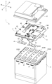
- FIG. 2 is a perspective view illustrating a configuration example of a power storage device.
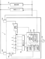
- FIG. 1 is a block diagram showing a configuration example of a power storage device including an estimation device;
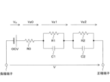
- FIG. 4 is a circuit diagram showing an example of a storage element model.
- 13 is a flowchart illustrating an example of a processing procedure executed by the estimation device.
- 13 is a flowchart illustrating an example of a processing procedure executed by an estimation device according to a second embodiment.
- An estimation device includes an acquisition unit that acquires the state of a storage element, and an estimation unit that estimates an SOC of the storage element that satisfies a predetermined charging capacity or discharging capacity based on the acquired state of the storage element and information on a current pattern provided to a model of the storage element.
- the “energy storage element” may be a power storage cell or a power storage unit having a plurality of power storage cells.
- the "energization pattern information” may include a current value representing the energization pattern and an energization time of the current value.
- SOC of a storage element that satisfies a specified charging or discharging capacity refers to the SOC of a storage element that can be charged or discharged in a specific current pattern without deviating from a specified voltage range, and is, for example, an SOC range defined by an upper limit and a lower limit of the SOC.
- the SOC of a storage element that satisfies a specified charging or discharging capacity is also referred to as a usable SOC range.
- the usable SOC range refers to an SOC that is suitable for use of the storage element.
- the estimation unit may use a model of the storage element to predict a voltage behavior of the storage element when a current is applied in the current application pattern, and may estimate an SOC value of the storage element based on the predicted voltage behavior of the storage element.
- the estimation unit may identify an SOC value of the storage element that can satisfy the predetermined charging capacity or discharging capacity by determining whether the voltage behavior of the storage element predicted by the model satisfies the predetermined charging capacity or discharging capacity.
- the estimation device described in (1) above can estimate the usable SOC range by taking into account the charging or discharging capacity (charging and discharging capacity) of the storage element.
- the usable SOC range can be dynamically estimated according to the required charging and discharging capacity, i.e., the expected current pattern. Compared to a case where a fixed usable SOC range is set in advance, the usable SOC range of the storage element can be flexibly adjusted, increasing the degree of freedom of the SOC.
- the storage element is a low-voltage battery mounted on a vehicle.
- a charge/discharge control device mounted on the vehicle controls charging and discharging so that the SOC of the storage element is within a specific SOC range while the vehicle is running. Also, while the vehicle is parked, the storage element is charged using the vehicle's high-voltage system or alternator when the specific SOC is reached, so that the storage element maintains an SOC that allows it to perform a specified power supply performance.
- a charge/discharge control device uses a preset fixed SOC range (e.g., SOC 70% to 80%) as the usable SOC range for charge/discharge control.
- SOC 70% to 80% the usable SOC range for charge/discharge control.
- the charge/discharge control device performs the above-mentioned charge/discharge control so that the current SOC of the storage element notified from the power storage device falls within the usable SOC range.
- the storage device judges at predetermined intervals whether charging or discharging using a predetermined current flow pattern (whether or not current can be passed) and notifies the vehicle of the judgment result. In this case, only whether current can be passed is judged, and it does not take into account what percentage of SOC must be above or below to allow current to be passed in the actual state of the storage element. In other words, the charge and discharge control of the storage element and the estimation of SOF are processed independently.
- the above configuration makes it possible to estimate the usable SOC range taking into account the charge/discharge capacity of the storage element.
- the SOC range in which charge/discharge control should be performed can be set broadly.
- the charge/discharge performance of the storage element can be fully utilized, the degree of freedom in energy management can be increased, and the power cost and fuel efficiency achieved by charging from the charging system can be improved.
- the state of the storage element may include at least one of the deterioration state, temperature, and polarization state of the storage element at the time of estimation.
- the “deterioration state” may be the capacity maintenance rate (SOH: State of health) of the storage element, the full charge capacity, or the rate of increase in internal resistance.
- SOH capacity maintenance rate
- the “polarization state” may be the degree of deviation between the theoretical electromotive force of the storage element and the actual operating voltage.
- the estimation device described in (2) above can accurately estimate the usable SOC range by taking into account the deterioration state and temperature of the storage element at the time of estimation, which greatly affect the voltage behavior of the storage element.
- the estimation time means the present, for example, if the estimation is performed in real time.
- the SOC of the storage element may include a lower limit value of the SOC of the storage element that satisfies a predetermined discharge capacity estimated based on information on a discharge pattern provided to the model.
- the estimation device described in (3) above can estimate the lower limit of the SOC at which discharge is possible in a predetermined discharge pattern, thereby optimizing discharge control.
- the lower limit of the SOC may be the lowest SOC value at which discharge is possible without falling below a predetermined threshold voltage.
- the SOC of the storage element may include an upper limit value of the SOC of the storage element that satisfies a predetermined charging capacity estimated based on information on a charging pattern provided to the model.
- the estimation device described in (4) above can estimate the upper limit of the SOC that can accept charging in a specified charging pattern, thereby optimizing charging control.
- the upper limit of the SOC may be the highest SOC value that can accept charging without exceeding a specified threshold voltage.
- the estimation unit may search for an upper or lower limit value of the SOC of the storage element by sequentially increasing or decreasing the SOC value from a starting SOC, and determining whether the voltage behavior of the storage element predicted by the model satisfies the predetermined charging or discharging capacity based on the SOC value of the storage element after the increase or decrease, the state of the storage element, and information on the current pattern.
- the parameters of the equivalent circuit model have SOC dependency.
- Finding an SOC value such that the predicted voltage by an equivalent circuit model including parameters that have SOC dependency becomes the threshold voltage requires complex calculations.
- the estimation device described in (5) above by sequentially changing the SOC value from the starting SOC, it is possible to efficiently and accurately search for an SOC value that satisfies a specified charge/discharge capacity, thereby reducing the computational load and computation time in estimating the SOC value.
- the estimation unit may derive a recommended SOC based on the estimated SOC of the storage element.
- the estimation device described in (6) above can set a recommended SOC that is recommended for use according to the estimated usable SOC range.
- the recommended SOC may be, for example, a part of the estimated usable SOC range, or may be a value that adds a predetermined required SOC to the estimated usable SOC range. For example, by setting a relatively low SOC range within the estimated SOC range as the recommended SOC range, it is possible to prevent the storage element from being repeatedly used in a high SOC band, and the effect of suppressing deterioration of the storage element can be expected.
- a temperature estimation unit may be provided that estimates the temperature of the storage element that satisfies a predetermined discharge capacity when the estimated lower limit value of the SOC of the storage element is equal to or greater than a threshold value.
- the estimation device described in (7) above can estimate the temperature of a storage element that can supply power, and therefore can appropriately perform temperature rise control of the storage element.
- the estimation device may include an output unit that outputs the estimated SOC of the storage element to an external device.
- the estimation device described in (8) above can reliably notify an external device of the estimation result.
- the estimation device described in (9) above can reliably notify the estimation result to an external device that performs charge/discharge control.
- the external device can appropriately control the charge/discharge of the storage element according to the estimation result.
- An energy storage device includes an energy storage element and an estimation device according to any one of (1) to (9) above.
- An estimation method acquires the state of a storage element, and estimates the SOC of the storage element that satisfies a predetermined charging or discharging capacity based on the acquired state of the storage element and information on a current pattern provided to a model of the storage element.
- An estimation program acquires the state of a storage element, and causes a computer to execute a process of estimating the SOC of the storage element that satisfies a predetermined charging capacity or discharging capacity based on the acquired state of the storage element and information on a current pattern provided to a model of the storage element.
- FIG. 1 is a perspective view showing a configuration example of the energy storage device 1
- Fig. 2 is an exploded perspective view of the energy storage device 1.
- the configuration example of the energy storage device 1 will be described with reference to the directions of "front-rear,”"left-right,” and “up-down" shown in the drawings.
- the power storage device 1 is a battery that is suitable for installation in, for example, engine vehicles, electric vehicles (EVs), hybrid electric vehicles (HEVs), plug-in hybrid electric vehicles (PHEVs), etc.
- the power storage device 1 is, for example, a 12 volt (V) battery or a 48 V battery.
- the energy storage device 1 includes a plurality of energy storage cells 2, an estimation device 3, and a busbar unit 4.
- the energy storage device 1 is an example of an energy storage element.
- the energy storage cells 2, the estimation device 3, and the busbar unit 4 are housed inside a housing case 10.
- the energy storage cells 2 are, for example, battery cells formed from lithium ion secondary batteries.
- the storage element is a storage unit having multiple storage cells 2.
- the storage element may be a single storage cell 2.
- the estimation device 3 is, for example, a battery management system (BMS).
- BMS battery management system
- the estimation device 3 acquires measurement data including the voltages of the storage cells 2 and the storage device 1, the current flowing through the storage cells 2, and the temperature related to the storage device 1.
- the estimation device 3 estimates the SOC (usable SOC range) of the storage device 1 that satisfies a specified charging capacity or discharging capacity based on the acquired measurement data.
- the usable SOC range of the storage device 1 is, for example, an SOC range defined by an upper limit and a lower limit of the SOC value.
- the estimation device 3 is mounted inside the energy storage device 1.
- the estimation device 3 may be installed remotely from the energy storage device 1.
- the estimation device 3 may be a computer such as a server device, a terminal device, or a vehicle ECU that is connected to the outside of the energy storage device 1.
- the measurement data measured regarding the energy storage device 1 may be transmitted to the server device, etc., via communication.
- the storage case 10 is made of synthetic resin.
- the storage case 10 comprises a case body 11 with an open top, and a cover 12 that covers the opening of the case body 11.
- the case body 11 and the cover 12 are fixed in a liquid-tight manner by fasteners such as screws, adhesives, welding, or the like, with the storage cell 2, the estimation device 3, and the busbar unit 4 housed therein.
- a pair of external terminals 13A, 13B with opposite polarities are provided on one side of the storage case 10.
- the storage cell 2 has a hollow rectangular parallelepiped case 21.
- a positive terminal 22 and a negative terminal 23 of the storage cell 2 are provided on the upper surface of the case 21.
- An electrode body, an electrolyte, and the like are contained inside the case 21.
- the electrode body is constructed by stacking a sheet-shaped positive electrode and a sheet-shaped negative electrode with two sheet-shaped separators between them, and then winding them (vertically or horizontally).
- the separators are made of a porous resin film.
- a porous resin film made of resin such as polyethylene (PE) or polypropylene (PP) can be used.
- the positive electrode is an electrode plate in which a positive electrode active material layer is formed on the surface of a long strip-shaped positive electrode substrate made of, for example, aluminum, an aluminum alloy, or the like.
- the positive electrode active material layer includes a positive electrode active material.
- a positive electrode active material used in the positive electrode active material layer a material capable of absorbing and releasing lithium ions can be used.
- the positive electrode active material for example, LiFePO4 can be mentioned.
- the positive electrode active material layer may further include a conductive assistant, a binder, and the like.
- the negative electrode is an electrode plate in which a negative electrode active material layer is formed on the surface of a long strip-shaped negative electrode substrate made of, for example, copper or a copper alloy.
- the negative electrode active material layer contains a negative electrode active material.
- the negative electrode active material can be a material capable of absorbing and releasing lithium ions. Examples of the negative electrode active material include graphite, hard carbon, and soft carbon.
- the negative electrode active material layer may further contain a binder, a thickener, and the like.
- the electrolyte may be the same as that used in conventional lithium ion secondary batteries.
- an electrolyte containing a supporting salt in an organic solvent may be used.
- aprotic solvents such as carbonates, esters, and ethers may be used as the organic solvent.
- lithium salts such as LiPF 6 , LiBF 4 , and LiClO 4 may be used as the supporting salt.
- the electrolyte may contain various additives such as a gas generating agent, a film forming agent, a dispersing agent, and a thickening agent.
- the storage cell 2 is a battery cell of a lithium ion secondary battery.
- the storage cell 2 may be a battery cell of an all-solid-state battery, a lead battery, a redox flow battery, a zinc-air battery, an alkaline manganese battery, a lithium-sulfur battery, a sodium-sulfur battery, a silver-zinc oxide battery, a nickel-metal hydride battery, a molten salt thermal battery, or the like, or may be a capacitor.
- the storage cell 2 is a rectangular battery cell with a wound electrode body.
- the storage cell 2 may be a cylindrical battery cell or a laminated (pouch) battery cell, or may be a battery cell with a laminated electrode body.
- the number of storage cells 2 housed in the case body 11 is four.
- the number of storage cells 2 housed in the case body 11 may be one or more and less than four, or may be more than four.
- the storage cells 2 are also referred to as the first storage cell 2A, the second storage cell 2B, the third storage cell 2C, and the fourth storage cell 2D, in that order from the front side of the case body 11.
- each storage cell 2 is housed in the case body 11 such that the positive terminals 22 and negative terminals 23 of adjacent storage cells 2 are oriented in opposite directions.
- the estimation device 3 is placed on the terminal surface of the storage cell 2 via a busbar unit 4.
- the busbar unit 4 includes a plurality of busbars 41 and a resin busbar frame 42 that holds these busbars 41.
- Each busbar 41 is connected to the underside of the estimation device 3 by a fastener 43 such as a screw.
- the storage cell 2 and the estimation device 3 are connected via the busbar 41.
- the bus bar 41 constitutes a charge/discharge path for the storage cells 2.
- the bus bar 41 is made of metal and is formed from a material with excellent electrical conductivity and high thermal conductivity, such as aluminum, aluminum alloy, copper, copper alloy, or stainless steel.
- the bus bar 41 electrically connects the positive terminal 22 of one storage cell 2 to the negative terminal 23 of the other storage cell 2 in adjacent storage cells 2.
- the bus bar 41 also connects the negative terminal 23 of the first storage cell 2A to one external terminal 13A, and connects the positive terminal 22 of the fourth storage cell 2D to the other external terminal 13B.
- the estimation device 3 includes a flat circuit board 61.
- a shutoff circuit 62, a temperature sensor 63, a current sensor 64, and a voltage sensor 65 are also mounted on the upper surface of the circuit board 61.
- the estimation device 3 may be configured as a circuit board unit in which the shutoff circuit 62, the temperature sensor 63, the current sensor 64, and the voltage sensor 65 are mounted on the circuit board 61.
- the interrupting circuit 62 is a circuit for connecting or interrupting the conductive path between the bus bar 41 connected to the positive terminal 22 of the fourth storage cell 2D and the bus bar 66 connected to the external terminal 13B.
- the interrupting circuit 62 is formed of a semiconductor switch such as a MOSFET (Metal Oxide Semiconductor Field Effect Transistor). By switching the interrupting circuit 62 from an on state to an off state, it is possible to interrupt the outflow of current from the storage cell 2 to the outside and the inflow of current from the outside to the storage cell 2.
- the interrupting circuit 62 may be formed of a relay switch.
- the temperature sensor 63 is, for example, a thermistor, a thermocouple, etc.
- the temperature sensor 63 measures the temperature related to the energy storage device 1.
- the temperature sensor 63 is disposed at a position sufficiently separated from the energized heating element (for example, the interrupter circuit 62, the bus bars 41, 66, the fastener 48, etc.) on the circuit board 61.
- the temperature data measured by the temperature sensor 63 represents the ambient temperature of the energy storage device 1 (the temperature around the energy storage cell 2).
- the energy storage element may further include a temperature sensor 63 disposed near the energized heating element on the circuit board 61 and measuring the temperature of the energized heating element on the circuit board 61. In this case, the temperature of the energy storage device 1 may be determined based on the ambient temperature of the energy storage device 1 and the temperature of the energized heating element on the circuit board 61.
- FIG. 3 is a block diagram showing an example of the configuration of a power storage device 1 equipped with an estimation device 3.
- the power storage device 1 is connected to a vehicle ECU (Electronic Control Unit) 71, an electrical load 72 such as electrical equipment, and an alternator (not shown) via external terminals 13A and 13B.
- ECU Electronic Control Unit
- an electrical load 72 such as electrical equipment
- an alternator not shown
- the alternator If the vehicle is an engine vehicle, while the engine is running, if the amount of power generated by the alternator is greater than the amount of power consumed by the electrical load 72, the electrical storage device 1 is charged by the alternator. If the amount of power generated by the alternator is less than the amount of power consumed by the electrical load 72, the electrical storage device 1 discharges to make up for the shortfall. When the vehicle is parked, the alternator stops generating power, so the electrical storage device 1 is not charged and only discharges to the vehicle ECU 71 and the electrical load 72.
- the power storage device 1 supplies power to start the high-voltage system. While the vehicle is parked, the power storage device 1 discharges to the vehicle ECU 71 and electrical loads 72, and can also be charged by the high-voltage system.
- the vehicle ECU 71 is a vehicle control unit that controls the vehicle.
- the vehicle ECU 71 controls the electrical load 72.
- the vehicle ECU 71 controls the charge or discharge amount of the power storage device 1 by controlling the electrical load 72 based on the estimation result of the usable SOC range received from the estimation device 3.
- the vehicle ECU 71 is an example of a higher-level device, and is an example of an external device (charge/discharge control device) that controls the charge and discharge of the power storage device 1.
- the estimation device 3 is a computer, and includes a control unit 31, a memory unit 32, an input/output unit 33, and a communication unit 34.
- the estimation device 3 is realized by a circuit board, but alternatively, the estimation device 3 may be configured to perform distributed processing using multiple computers, may be realized by multiple virtual machines provided in a single server, or may be realized using a cloud server.
- the control unit 31 is an arithmetic circuit equipped with a CPU (Central Processing Unit), a GPU (Graphics Processing Unit), a ROM (Read Only Memory), a RAM (Random Access Memory), etc.
- the CPU or GPU equipped in the control unit 31 executes various computer programs stored in the ROM or the storage unit 32, and controls the operation of each of the hardware components mentioned above.
- the control unit 31 may also have functions such as a timer that measures the elapsed time from when an instruction to start measurement is given to when an instruction to end measurement is given, a counter that counts numbers, and a clock that outputs date and time information.
- the storage unit 32 includes a non-volatile storage device such as a flash memory or a hard disk drive.
- the storage unit 32 stores various computer programs and data referenced by the control unit 31.
- the storage unit 32 may be an external storage device connected to the estimation device 3.
- the memory unit 32 of this embodiment stores an estimation program 321 for causing a computer to execute processing related to estimating the usable SOC range of the energy storage device 1, and estimation data 322 as data necessary for executing the estimation program 321.
- the estimation data 322 includes a storage element model used in the simulation.
- the storage element model is described by configuration information indicating the circuit configuration, and the values of each element that constitutes the storage element model.
- the memory unit 32 stores configuration information indicating the circuit configuration of the storage element model, and the values of each element that constitutes the storage element model.
- a computer program (computer program product) including the estimation program 321 may be provided by a non-transitory recording medium 3A on which the computer program is readably recorded.
- the recording medium 3A is, for example, a portable memory such as a magnetic disk, an optical disk, or a semiconductor memory.
- the control unit 31 reads the desired computer program from the recording medium 3A using a reading device (not shown) and stores the read computer program in the memory unit 32.
- the computer program may be provided by communication.
- the estimation program 321 may be a single computer program or may be composed of multiple computer programs, and may be executed on a single computer or on multiple computers interconnected by a communication network.
- the input/output unit 33 has an input/output interface for connecting to an external device.
- a cutoff circuit 62, a temperature sensor 63, a current sensor 64, a voltage sensor 65, etc. are connected to the input/output unit 33.
- the control unit 31 switches the interruption circuit 62 between an on state and an off state by outputting a control signal to the interruption circuit 62 via the input/output unit 33.
- the control unit 31 also acquires temperature data measured by the temperature sensor 63, current data measured by the current sensor 64, and voltage data measured by the voltage sensor 65 via the input/output unit 33 at any time.
- the current sensor 64 is, for example, a shunt resistor, and is connected in series to the storage cell 2.
- the current sensor 64 measures the current flowing through the storage cell 2 in a time series manner based on the voltage across the storage cell 2. Discharging and charging can be determined from the polarity (positive or negative) of the voltage across both ends.
- the current sensor 64 may be a magnetic sensor.
- the voltage sensor 65 is connected in parallel to each storage cell 2.
- the voltage sensor 65 is connected to both ends of each storage cell 2, and measures the terminal voltage of each storage cell 2 in time series.
- the control unit 31 acquires data on the voltage of each storage cell 2 measured by the voltage sensor 65 and the total voltage of the storage device 1 via the input/output unit 33.
- the input/output unit 33 may be connected to a display device such as a liquid crystal display device.
- the control unit 31 may output the estimated result of the usable SOC range via the input/output unit 33 and display it on the display device.
- the communication unit 34 includes a communication interface that realizes communication with an external device.
- the control unit 31 transmits and receives various data, including the estimation result of the usable SOC range, to and from the external device through the communication unit 34.
- the external device that is communicatively connected via the communication unit 34 may be the vehicle ECU 71.
- the following describes a method for estimating the usable SOC range using the estimation device 3.
- the following describes a method for estimating the usable SOC range using an example in which a usable SOC range that satisfies a specified discharge capacity is found based on information about a discharge pattern.
- the energy storage device 1 mounted on a moving object is required to exhibit a predetermined discharge capacity for the electrical load connected to it whenever the moving object is started (when a discharge is requested).
- a 12V battery mounted on a vehicle is required to maintain a voltage above a threshold value (e.g. 9V) even when discharging for a predetermined time (t seconds) at a discharge current specified by a higher-level device according to the power consumption of the on-board electrical load 72.
- the discharge capacity of the energy storage device 1 is not always constant, but changes depending on the operating conditions of the energy storage device 1, such as the temperature, SOH of the storage cells 2, and current.
- the estimation device 3 determines a usable SOC range according to the operating conditions by simulating the voltage behavior of the energy storage device 1 when it is discharged in a specified discharge pattern using a storage element model.
- the estimation device 3 sequentially estimates the voltage behavior of the energy storage device 1 by changing the SOC given to the storage element model, and determines whether or not discharge is possible according to the discharge pattern based on the estimated voltage behavior, thereby finding the optimal usable SOC range that satisfies the specified discharge capacity.
- FIG. 4 is a circuit diagram showing an example of a storage element model.
- the storage element model shown in FIG. 4 is an equivalent circuit model that combines a voltage source for the storage cell 2 and circuit elements such as a resistor and a capacitor to simulate the charging and discharging behavior of the storage cell 2.
- the equivalent circuit model includes, for example, a constant voltage source, a DC resistor, and an RC parallel circuit that are connected in series between the positive and negative terminals.
- FIG. 4 shows an equivalent circuit model in which two RC parallel circuits, a first RC parallel circuit and a second RC parallel circuit, are connected in series, but the RC parallel circuit is not limited to two stages.
- the constant voltage source is a voltage source that outputs a DC voltage.
- the voltage output by the constant voltage source is the open circuit voltage (OCV) of the storage cell 2, and is represented as Vo(t).
- OCV open circuit voltage
- Vo(t) The open circuit voltage Vo(t) is given as a function of the SOC, temperature, SOH, etc. of the storage cell 2.
- the DC resistor is used to describe the DC resistance component (DC impedance) of the storage cell 2, and includes a resistance element R0.
- the value of the resistance element R0 is given as a value that changes according to the SOC, temperature, SOH, etc.
- the value of the resistance element R0 may also be given as a value that changes according to the current flowing through it.
- the two RC parallel circuits are circuit elements for describing the transient polarization characteristics of the storage cell 2.
- the first RC parallel circuit is composed of a resistive element R1 and a capacitive element C1 connected in parallel.
- the second RC parallel circuit is composed of a resistive element R2 and a capacitive element C2 connected in parallel.
- the values of the resistive elements R1, R2 and the capacitive elements C1, C2 are given as values that vary depending on the current flow, SOC, temperature, etc.
- the impedances of the first RC parallel circuit and the second RC parallel circuit are determined by the resistive elements R1, R2 and the capacitive elements C1, C2.
- the polarization voltage is the sum of the polarization voltage Vz1(t) generated in the first RC parallel circuit and the polarization voltage Vz2(t) generated in the second RC parallel circuit.
- the time constant in the first RC parallel circuit is ⁇ 1
- the time constant in the second RC parallel circuit is ⁇ 2.
- the time constant ⁇ 1 is determined as the product of the resistance value of the resistive element R1 and the capacitance value of the capacitive element C1 that constitute the first RC parallel circuit.
- the time constant ⁇ 1 is reflected in the time change of the polarization voltage Vz1(t) generated in the first RC parallel circuit.
- the time constant ⁇ 2 is determined as the product of the resistance value of the resistive element R2 and the capacitance value of the capacitive element C2 that constitute the second RC parallel circuit.
- the time constant ⁇ 2 is reflected in the time change of the polarization voltage Vz2(t) generated in the second RC parallel circuit.
- the terminal voltage V(t) between the positive and negative terminals of the storage cell 2 after a time t has elapsed can be expressed by the following formula (1) using the DC resistance voltage Vz0(t), the polarization voltage Vz1(t), the polarization voltage Vz2(t), and the open circuit voltage Vo(t).
- V(t) Vo(t)+Vz0(t)+Vz1(t)+Vz2(t)...(1)
- the estimated voltage of the energy storage device 1 is calculated by calculating the sum of the terminal voltages V(t) of each storage cell 2 obtained by equation (1).
- the values of each of the elements R0, R1, R2, C1, and C2 constituting the equivalent circuit model of the storage cell 2 are set in advance, for example, based on the results of actual measurements and taking into consideration the relationships between current, voltage, SOC, SOH, temperature, etc.
- the estimation device 3 stores a parameter table in which the values of each element are stored in association with temperature, SOC, SOH, current flow, etc., as estimation data 322 in the storage unit 32.
- the estimation data 322 stored in the estimation device 3 may also include a profile (SOC-OCV characteristics) showing the relationship between SOC and OCV in association with temperature and SOH.
- the OCV and the values of each of the elements R0, R1, R2, C1, and C2 in the equivalent circuit model are also referred to as circuit parameters.
- the estimation device 3 uses an equivalent circuit model to estimate the estimated voltage when discharging in a specified discharge pattern, and judges whether or not current can be passed based on the estimation result.
- Information on the discharge pattern is specified, for example, from a higher-level device.
- the information on the discharge pattern may include a current value, current passing time, and an operating voltage range related to the discharge pattern.
- the operating voltage range is the lower limit voltage of the storage device 1 when discharging, and is given the upper limit voltage of the storage device 1 when charging.
- determining whether or not current can be passed it is determined whether the estimated voltage of the storage device 1 due to discharge in a specified discharge pattern is equal to or greater than a preset lower limit voltage value. If the estimated voltage value after discharge in the discharge pattern is equal to or greater than the lower limit voltage value, it can be determined that the discharge capacity after current is met and discharge is possible. If the estimated voltage value after discharge is less than the lower limit voltage value, it can be determined that the discharge capacity after current is not met and discharge is not possible. Whether or not current can be passed corresponds to whether or not a specified charge capacity or discharge capacity is met.
- the estimation device 3 uses a certain starting SOC value as the initial value and searches for the optimal lower limit of the SOC that defines the usable SOC range.
- FIG. 5 is a flowchart showing an example of a processing procedure executed by the estimation device 3.
- the processing in the following flowchart is executed by the control unit 31 in accordance with a computer program 3P stored in the storage unit 32 of the estimation device 3.
- the control unit 31 of the estimation device 3 acquires measurement data including the current temperature, current, and voltage of the energy storage device 1 by functioning as an acquisition unit (step S11).
- the control unit 31 acquires the current SOH of the energy storage device 1, which is calculated based on the acquired measurement data (step S12).
- the control unit 31 determines the starting SOC value (step S13).
- the control unit 31 may store in advance in the storage unit 32 a correspondence relationship between the SOH and/or temperature and the starting SOC value to be used, and may identify a starting SOC corresponding to the current SOH and/or temperature of the storage device 1 based on the correspondence relationship.
- the correspondence relationship between the SOH and/or temperature and the starting SOC value to be used can be set based on, for example, the results of actual measurement. Alternatively, the starting SOC value may be selected arbitrarily.
- the control unit 31 derives circuit parameters in the equivalent circuit model based on the determined starting SOC value, the current temperature and SOH, and the discharge pattern information provided by the higher-level device (step S14).
- the control unit 31 determines the circuit parameters so as to correspond to the SOC value, temperature, SOH, and discharge pattern information as the simulation conditions, for example, by referring to the parameter table and SOC-OCV characteristics of the estimated data 322.
- the control unit 31 applies the derived circuit parameters and predicts the voltage behavior of the storage device 1 when discharging according to the discharge pattern using an equivalent circuit model, thereby determining whether or not discharging according to the discharge pattern is possible at the starting SOC value (step S15).
- the control unit 31 estimates the estimated voltage of the storage device 1 by substituting the derived circuit parameters into the above formula (1), and determines whether or not discharging is possible by determining whether or not the estimated voltage is equal to or greater than a preset lower limit voltage value.
- the control unit 31 reduces the SOC value by a predetermined amount from the starting SOC value (step S16).
- the amount of reduction in the SOC value may be set in advance.
- the control unit 31 derives new circuit parameters in the equivalent circuit model to correspond to the new simulation conditions (step S17).
- the control unit 31 applies the derived new circuit parameters and predicts the voltage behavior of the storage device 1 when discharging according to the discharge pattern using an equivalent circuit model, thereby determining whether or not discharging according to the discharge pattern is impossible with the reduced SOC value (step S18).
- control unit 31 If it is determined that discharge is possible with the reduced SOC value, i.e., discharge is possible (S18: NO), the control unit 31 returns the process to step S16, further reduces the SOC value by a predetermined amount from the reduced SOC value, and repeats the same process.
- control unit 31 estimates the SOC value immediately before it is determined that discharging is not possible as the lower limit SOC value (step S19), and the process proceeds to step S24.
- the control unit 31 increases the SOC value by a predetermined amount from the starting SOC value (step S20).
- the amount of increase in the SOC value may be set in advance.
- the control unit 31 derives new circuit parameters in the equivalent circuit model to correspond to the new simulation conditions (step S21).
- the control unit 31 applies the derived new circuit parameters and predicts the voltage behavior of the storage device 1 when discharging according to the discharge pattern using an equivalent circuit model, thereby determining whether or not discharging according to the discharge pattern is possible with the increased SOC value (step S22).
- control unit 31 If it is determined that discharge is not possible with the increased SOC value, i.e., discharge is not possible (S22: NO), the control unit 31 returns the process to step S20, further increases the SOC value by a predetermined amount from the increased SOC value, and repeats the same process.
- control unit 31 estimates the SOC value at which it is determined that discharge is possible as the lower limit SOC value (step S23), and the process proceeds to step S24.
- the control unit 31 may perform the processes from step S13 to step S24 described above by functioning as an estimation unit.
- the control unit 31 outputs the usable SOC range indicated by the estimated lower limit value of the SOC and a preset upper limit value of the SOC (e.g., SOC 80%) to an external device (e.g., the vehicle ECU 71) (step S24), and ends the series of processes.
- a preset upper limit value of the SOC e.g., SOC 80%
- the estimation device 3 may replace the discharge pattern in the above description with a charge pattern and perform similar processing on the charge pattern to determine the upper limit SOC value that satisfies a specified charge capacity based on the charge pattern.
- the usable SOC range may be indicated by the lower limit SOC value that satisfies the specified discharge capacity and the upper limit SOC value that satisfies the specified charge capacity.
- the estimation device 3 may derive a recommended SOC range based on the lower and upper limits of the SOC, and output the derived recommended SOC range to an external device.
- the estimation device 3 derives the recommended SOC range, for example, by adding or subtracting an SOC corresponding to a predetermined required power to or from the determined lower and/or upper limits of the SOC, so as to set the new lower and/or upper limits.
- the estimation device 3 may set the lower limit of the recommended SOC range to a value that is greater than the estimated lower limit of the SOC by an SOC corresponding to the required power during parking.
- the estimation device 3 may derive a range that is a portion of the estimated usable SOC range and is limited to a specific SOC range, as the recommended SOC range.
- the recommended SOC range may be set to an SOC of 50% or less, to encourage the use of the power storage device 1 in a low SOC range.
- the estimation device, estimation method, and estimation program may be applicable to applications other than vehicles, and may be applied to flying objects such as aircraft, flying vehicles, and HAPS (High Altitude Platform Stations), as well as to ships and submarines.
- the power storage device 1 may be a high-voltage battery.
- the SOC suitable for use can be estimated by taking into account the charging or discharging capacity according to the operating conditions of the storage device 1.
- Second Embodiment when the estimated lower limit value of the SOC is equal to or greater than a threshold value, a temperature that satisfies a predetermined discharge capacity is estimated.
- a threshold value a temperature that satisfies a predetermined discharge capacity
- FIG. 6 is a flowchart showing an example of a processing procedure executed by the estimation device 3 of the second embodiment.
- the control unit 31 of the estimation device 3 starts the following processing after executing, for example, step S20 of the first embodiment.
- the control unit 31 of the estimation device 3 determines whether the increased SOC value has reached 100% (step S31). If it is determined that the increased SOC value has not reached 100% (S31: NO), the control unit 31 ends the process.
- control unit 31 derives the circuit parameters of the equivalent circuit model based on the current temperature, the current SOH, the set SOC value (e.g., SOC 100%), and the discharge pattern information provided from the higher-level device to correspond to the above simulation conditions (step S32).
- the control unit 31 applies the derived circuit parameters and predicts the voltage behavior of the storage device 1 when discharging according to the discharge pattern using an equivalent circuit model, thereby determining whether discharging according to the discharge pattern is possible at the current temperature (step S33).
- control unit 31 ends the process.
- the control unit 31 If it is determined that discharge is not possible at the current temperature, i.e., discharge is not possible (S33: NO), the control unit 31 increases the temperature value of the storage device 1 from the current temperature by a predetermined amount (step S34). The amount of increase in temperature may be set in advance. Based on the increased temperature, the current SOH and SOC settings, and information on the discharge pattern, the control unit 31 derives new circuit parameters in the equivalent circuit model to correspond to the new simulation conditions (step S35).
- the control unit 31 applies the derived new circuit parameters and predicts the voltage behavior of the storage device 1 when discharging according to the discharge pattern using an equivalent circuit model, thereby determining whether discharging according to the discharge pattern is possible at the increased temperature (step S36).
- control unit 31 If it is determined that discharge is not possible at the increased temperature, i.e., discharge is not possible (S36: NO), the control unit 31 returns the process to step S34, further increases the temperature value by a predetermined amount from the increased temperature, and repeats the same process.
- the control unit 31 estimates the temperature of the power storage device 1 when it is determined that discharge is possible as the minimum temperature (step S37).
- the control unit 31 outputs the estimated minimum temperature to an external device (e.g., the vehicle ECU 71) (step S38), and ends the series of processes.
- the external device performs temperature increase control, such as activating the vehicle heater, based on the minimum temperature received from the estimation device 3.
- step S31 the estimation device 3 may determine whether the increased SOC value is equal to or greater than a preset threshold value.
- the SOC that is the starting condition for the processing in FIG. 6 is not limited to 100%.
- the circuit parameters are derived based on the set value of the SOC as a simulation condition, and it is determined whether or not to allow current to flow.
- the circuit parameters may be derived based on the current SOC of the storage device 1.
- Energy storage device energy storage element
- Storage cell Estimation device
- Control unit Storage unit 33
- Input/output unit 34
- Communication unit 321
- Estimation program 322 Estimation data 3A Recording medium
Landscapes
- Physics & Mathematics (AREA)
- General Physics & Mathematics (AREA)
- Engineering & Computer Science (AREA)
- Power Engineering (AREA)
- Manufacturing & Machinery (AREA)
- Chemical & Material Sciences (AREA)
- Chemical Kinetics & Catalysis (AREA)
- Electrochemistry (AREA)
- General Chemical & Material Sciences (AREA)
- Secondary Cells (AREA)
- Charge And Discharge Circuits For Batteries Or The Like (AREA)
- Tests Of Electric Status Of Batteries (AREA)
Abstract
推定装置は、電素子の状態を取得する取得部と、取得した前記蓄電素子の状態と、前記蓄電素子のモデルに与えられる通電パターンの情報とに基づいて、所定の充電能力又は放電能力を満たす前記蓄電素子のSOCを推定する推定部とを備える。
Description
本発明は、推定装置、蓄電装置、推定方法及び推定プログラムに関する。
二次電池は、電気自動車(EV)、ハイブリッド電気自動車(HEV)、又はプラグインハイブリッド電気自動車(PHEV)等の車両や、その他移動体用の電源として広く用いられている。二次電池の充放電制御を行うための充放電装置に関する技術が開示されている(例えば、特許文献1)。
充放電装置は、一般的に、二次電池のSOCが予め設定される使用SOC範囲内となるよう充放電制御を行う。従来、使用SOC範囲の設定において蓄電素子の充電能力又は放電能力が考慮されていない。
本開示の目的は、蓄電素子の充電能力又は放電能力を考慮して使用に適した蓄電素子のSOCを推定できる技術を提供することである。
本開示の一態様に係る推定装置は、電素子の状態を取得する取得部と、取得した前記蓄電素子の状態と、前記蓄電素子のモデルに与えられる通電パターンの情報とに基づいて、所定の充電能力又は放電能力を満たす前記蓄電素子のSOCを推定する推定部とを備える。
本開示によれば、蓄電素子の充電能力又は放電能力を考慮して使用に適した蓄電素子のSOCを推定できる。
(1)本開示の一態様に係る推定装置は、蓄電素子の状態を取得する取得部と、取得した前記蓄電素子の状態と、前記蓄電素子のモデルに与えられる通電パターンの情報とに基づいて、所定の充電能力又は放電能力を満たす前記蓄電素子のSOCを推定する推定部とを備える。
ここで、「蓄電素子」は、蓄電セルであってもよいし、複数の蓄電セルを有する蓄電ユニットであってもよい。
「通電パターンの情報」は、通電パターンを表す電流値及び当該電流値の通電時間を含んでもよい。
「所定の充電能力又は放電能力を満たす蓄電素子のSOC」は、所定の電圧範囲を逸脱することなく、特定の通電パターンで充電又は放電することが可能な蓄電素子のSOCであり、例えばSOCの上限値及び下限値で規定されるSOC範囲である。以下、所定の充電能力又は放電能力を満たす蓄電素子のSOCを、使用可能SOC範囲とも記載する。使用可能SOC範囲は、蓄電素子の使用に適したSOCを意味する。
推定部は、前記蓄電素子のモデルを用いて前記通電パターンで通電した際の前記蓄電素子の電圧挙動を予測し、予測した前記蓄電素子の電圧挙動に基づいて前記蓄電素子のSOC値を推定してもよい。推定部は、前記モデルにより予測された前記蓄電素子の電圧挙動が、前記所定の充電能力又は放電能力を満たすか否かを判定することにより、前記所定の充電能力又は放電能力を満たし得る前記蓄電素子のSOC値を特定してもよい。
「通電パターンの情報」は、通電パターンを表す電流値及び当該電流値の通電時間を含んでもよい。
「所定の充電能力又は放電能力を満たす蓄電素子のSOC」は、所定の電圧範囲を逸脱することなく、特定の通電パターンで充電又は放電することが可能な蓄電素子のSOCであり、例えばSOCの上限値及び下限値で規定されるSOC範囲である。以下、所定の充電能力又は放電能力を満たす蓄電素子のSOCを、使用可能SOC範囲とも記載する。使用可能SOC範囲は、蓄電素子の使用に適したSOCを意味する。
推定部は、前記蓄電素子のモデルを用いて前記通電パターンで通電した際の前記蓄電素子の電圧挙動を予測し、予測した前記蓄電素子の電圧挙動に基づいて前記蓄電素子のSOC値を推定してもよい。推定部は、前記モデルにより予測された前記蓄電素子の電圧挙動が、前記所定の充電能力又は放電能力を満たすか否かを判定することにより、前記所定の充電能力又は放電能力を満たし得る前記蓄電素子のSOC値を特定してもよい。
上記(1)に記載の推定装置によれば、蓄電素子の充電能力又は放電能力(充放電能力)を考慮して使用可能SOC範囲を推定することができる。求められる充放電能力、すなわち想定される通電パターンに応じて、動的に使用可能SOC範囲を推定できる。固定の使用可能SOC範囲を予め設定する場合と比べて、蓄電素子の使用可能SOC範囲を柔軟に調整することができ、SOCの自由度が高まる。
一例として、蓄電素子が車両に搭載される低電圧バッテリである場合を挙げて説明する。車両に搭載される充放電制御装置は、車両の走行中において、蓄電素子のSOCが特定のSOC範囲内となるよう、充放電を制御する。また、車両の駐車中、蓄電素子が所定の電力供給性能を発揮し得るSOCを維持するよう、特定のSOCとなった時点で車両の高電圧システム又はオルタネータを用いて蓄電素子の充電を行う。
従来、充放電制御装置は、充放電制御を行う使用可能SOC範囲として、予め設定された固定のSOC範囲(例えばSOC70%~80%)を用いる。蓄電素子を備える蓄電装置では、現在の蓄電素子のSOCを常時監視しておき、充放電制御装置へ通知する。充放電制御装置は、蓄電装置から通知された現在の蓄電素子のSOCが、使用可能SOC範囲に収まるよう、上述の充放電制御を実施する。予め使用可能SOC範囲を設定する場合、蓄電素子の使用状態に関わらず確実に電力供給性能を発揮できるよう、比較的狭いSOC範囲が設定される。このため蓄電素子の性能が十分に発揮されない。走行中において、実際にはより広いSOC範囲を使用可能であるにも関わらず、狭いSOC範囲で充放電が制御されてしまう。駐車中において、実際にはまだ充電を行う必要がないにも関わらず、高いSOC下で再充電が行われる。
上述した蓄電素子の充放電制御が行われる一方で、近年、車両における自動運転機能や安全機能を実現するため、蓄電素子の電力供給性能(SOF:State Of Function)を推定する機能が求められている。蓄電装置では、所定の通電パターンによる充電又は放電の可否(通電可否)を所定間隔で判定し、判定結果を車両へ通知している。その際、通電の可否のみが判定され、実際の蓄電素子の状態においてSOCが何%以上又は何%以下であれば通電が可能であるかまでは考慮されていない。換言すれば、蓄電素子の充放電制御と、SOFの推定とは独立して処理が行われている。
上記構成によれば、蓄電素子の充放電能力を考慮して使用可能SOC範囲を推定できる。蓄電素子の充放電能力を考慮して使用可能SOC範囲を動的に推定することで、充放電制御すべきSOC範囲を広く設定することができる。蓄電素子の充放電性能を十分に発揮し、エネルギーマネジメントの自由度を高め、充電システムからの充電による電費及び燃費の向上を図ることができる。充電においては、再充電を実施するSOCを固定値として予め設定する場合に比べて、再充電が遅すぎることにより車両起動後に車両機能が制限されることを抑制するとともに、再充電が早すぎることにより駐車中に頻繁に車両を起動することを抑制できる。
(2)上記(1)に記載の推定装置において、前記蓄電素子の状態は、推定時点における前記蓄電素子の劣化状態、温度及び分極状態の少なくともいずれかを含んでもよい。
「劣化状態」は、蓄電素子の容量維持率(SOH:State of health)であってもよく、満充電容量であってもよく、内部抵抗上昇率であってもよい。「分極状態」は、蓄電素子の理論起電圧と実際の作動電圧とのずれの度合いであってもよい。
上記(2)に記載の推定装置によれば、蓄電素子の電圧挙動に大きく影響を及ぼす推定時点の蓄電素子の劣化状態及び温度を加味して、使用可能SOC範囲を精度よく推定できる。推定時点は、例えばリアルタイムで推定を行う場合であれば、現在を意味する。
(3)上記(1)又は(2)に記載の推定装置において、前記蓄電素子のSOCは、前記モデルに与えられる放電パターンの情報に基づいて推定される所定の放電能力を満たす前記蓄電素子のSOCの下限値を含んでもよい。
上記(3)に記載の推定装置によれば、所定の放電パターンで放電可能なSOCの下限値を推定できるため、放電制御を最適化できる。SOCの下限値は、所定の閾値電圧を下回ることなく放電可能な最低SOC値であってもよい。
(4)上記(1)から(3)のいずれか1つに記載の推定装置において、前記蓄電素子のSOCは、前記モデルに与えられる充電パターンの情報に基づいて推定される所定の充電能力を満たす前記蓄電素子のSOCの上限値を含んでもよい。
上記(4)に記載の推定装置によれば、所定の充電パターンで充電受け入れ可能なSOCの上限値を推定できるため、充電制御を最適化できる。SOCの上限値は、所定の閾値電圧を上回ることなく充電受け入れ可能な最高SOC値であってもよい。
(5)上記(1)から(4)のいずれか1つに記載の推定装置において、前記推定部は、開始SOCからSOC値を順次増加又は減少させ、増加又は減少後の前記蓄電素子のSOC値と、前記蓄電素子の状態と、前記通電パターンの情報とに基づいて、前記モデルにより予測された前記蓄電素子の電圧挙動が前記所定の充電能力又は放電能力を満たすか否かを判定することにより、前記蓄電素子のSOCの上限値又は下限値を探索してもよい。
例えば、蓄電素子のモデルとしての等価回路モデルを用いて電圧挙動を予測することにより、所定の充放電電能力を満たすSOC値を探索する場合、等価回路モデルのパラメータはSOC依存性を有する。SOC依存性を有するパラメータを含む等価回路モデルによる予測電圧が閾値電圧となるようなSOC値を求めることは、複雑な計算を要する。上記(5)に記載の推定装置によれば、開始SOCから順次SOC値を変化させることにより、所定の充放電能力を満たすSOC値を効率的且つ精度よく探索できるため、SOC値の推定における演算負荷や演算時間を低減できる。
(6)上記(1)から(5)のいずれか1つに記載の推定装置において、前記推定部は、推定した前記蓄電素子のSOCに基づいて推奨SOCを導出してもよい。
上記(6)に記載の推定装置によれば、推定した使用可能SOC範囲に応じて使用を推奨する推奨SOCを設定できる。推奨SOCは、例えば、推定した使用可能SOC範囲のうちの一部のSOC範囲であってもよく、推定した使用可能SOC範囲に所定の必要SOCを加味した値であってもよい。例えば推定したSOC範囲のうち、比較的低いSOC範囲を推奨SOC範囲とすることで、蓄電素子が高SOC帯で繰り返し使用されることを防止し、蓄電素子の劣化抑制効果が期待できる。
(7)上記(1)から(6)のいずれか1つに記載の推定装置において、推定した前記蓄電素子のSOCの下限値が閾値以上である場合、所定の放電能力を満たす前記蓄電素子の温度を推定する温度推定部を備えてもよい。
蓄電素子の温度が低すぎると、SOCが所定値(例えばSOC100%)となるまで充電された場合であっても、所定の放電パターンによる電力供給ができないと判定される可能性がある。上記(7)に記載の推定装置によれば、そのような場合において、電力供給が可能な蓄電素子の温度を推定することができるため、蓄電素子の昇温制御を好適に実施できる。
(8)上記(1)から(7)のいずれか1つに記載の推定装置において、推定した前記蓄電素子のSOCを外部装置へ出力する出力部を備えてもよい。
上記(8)に記載の推定装置によれば、推定結果を外部装置へ確実に報知できる。
(9)上記(1)から(8)のいずれか1つに記載の推定装置において、推定した前記蓄電素子のSOCを前記蓄電素子の充放電制御を行う外部装置へ出力する出力部を備えてもよい。
上記(9)に記載の推定装置によれば、推定結果を充放電制御を行う外部装置へ確実に報知できる。推定結果に応じて外部装置において蓄電素子の充放電制御を好適に実行できる。
(10)本開示の一態様に係る蓄電装置は、蓄電素子と、上記(1)から(9)のいずれか1つに記載の推定装置とを備える。
(11)本開示の一態様に係る推定方法は、蓄電素子の状態を取得し、取得した前記蓄電素子の状態と、前記蓄電素子のモデルに与えられる通電パターンの情報とに基づいて、所定の充電能力又は放電能力を満たす前記蓄電素子のSOCを推定する。
(12)本開示の一態様に係る推定プログラムは、蓄電素子の状態を取得し、取得した前記蓄電素子の状態と、前記蓄電素子のモデルに与えられる通電パターンの情報とに基づいて、所定の充電能力又は放電能力を満たす前記蓄電素子のSOCを推定する処理をコンピュータに実行させる。
以下、本開示をその実施の形態を示す図面を参照して具体的に説明する。
(第1実施形態)
図1は蓄電装置1の構成例を示す斜視図、図2は蓄電装置1の分解斜視図である。以下では、図中に示す「前後」、「左右」、及び「上下」の各方向を参照しながら、蓄電装置1の構成例について説明する。
図1は蓄電装置1の構成例を示す斜視図、図2は蓄電装置1の分解斜視図である。以下では、図中に示す「前後」、「左右」、及び「上下」の各方向を参照しながら、蓄電装置1の構成例について説明する。
蓄電装置1は、例えば、エンジン車両、電気自動車(EV)、ハイブリッド電気自動車(HEV)、プラグインハイブリッド電気自動車(PHEV)等に好適に搭載されるバッテリーである。蓄電装置1は、例えば12ボルト(V)バッテリー又は48Vバッテリーである。
蓄電装置1は、複数の蓄電セル2、推定装置3、及びバスバーユニット4を備える。蓄電装置1は、蓄電素子の一例である。蓄電セル2、推定装置3、及びバスバーユニット4は、収容ケース10の内部に収容される。蓄電セル2は、例えばリチウムイオン二次電池による電池セルである。
実施の形態において、蓄電素子は、複数の蓄電セル2を有する蓄電ユニットである。代替的に、蓄電素子は単一の蓄電セル2であってもよい。
推定装置3は、例えば電池管理システム(BMS:Battery Management system)である。推定装置3は、蓄電セル2及び蓄電装置1の電圧、蓄電セル2に流れる電流、並びに蓄電装置1に関する温度を含む計測データを取得する。推定装置3は、取得した計測データに基づいて、所定の充電能力又は放電能力を満たす蓄電装置1のSOC(使用可能SOC範囲)を推定する。蓄電装置1の使用可能SOC範囲は、例えばSOC値の上限値及び下限値で規定されるSOC範囲である。
実施の形態において、推定装置3は、蓄電装置1の内部に搭載されている。代替的に、推定装置3は、蓄電装置1から離隔して設置されてもよい。推定装置3は、蓄電装置1の外部に接続されるサーバ装置、端末装置又は車両ECUなどのコンピュータであってもよい。この場合、蓄電装置1に関して計測される計測データは、通信によりサーバ装置等へ送信されるとよい。
収容ケース10は合成樹脂製である。収容ケース10は、上面が開口したケース本体11と、ケース本体11の開口を覆うカバー12とを備える。ケース本体11及びカバー12は、蓄電セル2、推定装置3、及びバスバーユニット4を収容した状態にて、ネジ等の締結具、接着剤又は溶着等により液密に固着される。収容ケース10の一側面には、極性が異なる一対の外部端子13A,13Bが設けられる。
蓄電セル2は、中空直方体状のケース21を備える。ケース21の上面には蓄電セル2の正端子22及び負端子23が設けられている。ケース21の内部には図示を省略する電極体及び電解液等が収容される。
電極体は、シート状の正極と、負極とを、2枚のシート状のセパレータを介して重ね合わせ、これらを巻回(縦巻き又は横巻き)することにより構成される。セパレータは、多孔性の樹脂フィルムにより形成される。多孔性の樹脂フィルムとして、ポリエチレン(PE)、ポリプロピレン(PP)等の樹脂からなる多孔性樹脂フィルムを使用できる。
正極は、例えばアルミニウム、アルミニウム合金等からなる長尺帯状の正極基材の表面に、正極活物質層が形成された電極板である。正極活物質層は、正極活物質を含む。正極活物質層に用いられる正極活物質としては、リチウムイオンを吸蔵放出可能な材料を使用できる。正極活物質としては、例えばLiFePO4が挙げられる。正極活物質層は、導電助剤、バインダ等を更に含んでもよい。
負極は、例えば銅又は銅合金等からなる長尺帯状の負極基材の表面に、負極活物質層が形成された電極板である。負極活物質層は、負極活物質を含む。負極活物質は、リチウムイオンを吸蔵放出可能な材料を使用できる。負極活物質としては、例えば黒鉛(グラファイト)、ハードカーボン、ソフトカーボン等が挙げられる。負極活物質層は、バインダ、増粘剤等を更に含んでもよい。
電解質には、従来のリチウムイオン二次電池と同様のものを使用できる。例えば、電解質として、有機溶媒中に支持塩を含有させた電解質を使用できる。有機溶媒として、例えば、カーボネート類、エステル類、エーテル類等の非プロトン性溶媒が用いられる。支持塩として、例えば、LiPF6、LiBF4、LiClO4等のリチウム塩が好適に用いられる。電解質は、例えば、ガス発生剤、被膜形成剤、分散剤、増粘剤等の各種添加剤を含んでもよい。
実施の形態において、蓄電セル2は、リチウムイオン二次電池による電池セルである。代替的に、蓄電セル2は、全固体電池、鉛電池、レドックスフロー電池、亜鉛空気電池、アルカリマンガン電池、リチウム硫黄電池、ナトリウム硫黄電池、酸化銀亜鉛電池、ニッケル水素電池、溶融塩熱電池などによる電池セルであってもよいし、キャパシタであってもよい。
実施の形態において、蓄電セル2は、巻回型の電極体を備えた角型の電池セルである。代替的に、蓄電セル2は、円筒型の電池セル、又はラミネート型(パウチ型)の電池セルであってもよく、積層型の電極体を備えた電池セルであってもよい。
実施の形態において、ケース本体11に収容されている蓄電セル2の数は4個である。代替的に、ケース本体11に収容される蓄電セル2の数は、1個以上4個未満であってもよく、4個超であってもよい。以下の説明では、蓄電セル2を、ケース本体11の前側から順に、第1蓄電セル2A、第2蓄電セル2B、第3蓄電セル2C、第4蓄電セル2Dとも記載する。
図2に示すように、各蓄電セル2は、隣り合う蓄電セル2の正端子22及び負端子23の向きが逆となるようケース本体11に収容される。
蓄電セル2の端子面上に、バスバーユニット4を介して推定装置3が配置される。バスバーユニット4は、複数のバスバー41と、これらのバスバー41を保持する樹脂製のバスバーフレーム42とを備える。各バスバー41は、ネジ等の締結具43によって推定装置3の下面に連結される。バスバー41を介して、蓄電セル2と推定装置3とが接続される。
バスバー41は、蓄電セル2に対する充放電経路を構成する。バスバー41は、金属製であり、アルミニウム、アルミニウム合金、銅、銅合金、ステンレス鋼等の導電性に優れ、熱伝導性が高い材料により形成される。バスバー41により、隣り合う蓄電セル2において、一方の蓄電セル2の正端子22と、他方の蓄電セル2の負端子23とが電気的に接続される。また、バスバー41により、第1蓄電セル2Aの負端子23と一方の外部端子13Aとが接続されるとともに、第4蓄電セル2Dの正端子22と他方の外部端子13Bとが接続される。
図1及び図2では、4個の蓄電セル2がバスバー41により直列に接続されている構成を説明した。代替的に、蓄電セル2は一部又は全部が並列に接続されてもよい。
推定装置3は、平板状の回路基板61を備える。回路基板61の上面にはまた、遮断回路62、温度センサ63、電流センサ64及び電圧センサ65(図3参照)などが搭載される。推定装置3は、遮断回路62、温度センサ63、電流センサ64及び電圧センサ65を回路基板61上に搭載した回路基板ユニットとして構成されてもよい。
遮断回路62は、第4蓄電セル2Dの正端子22に接続されるバスバー41と、外部端子13Bに接続されるバスバー66との間の導通路を接続又は遮断するための回路である。遮断回路62は、例えば、MOSFET(Metal Oxide Semiconductor Field Effect Transistor)などの半導体スイッチにより構成される。遮断回路62をオン状態からオフ状態に切り替えることで、蓄電セル2から外部への電流の流出、及び外部から蓄電セル2への電流の流入を遮断できる。代替的に、遮断回路62は、リレースイッチにより構成されてもよい。
温度センサ63は、例えばサーミスタ、熱電対等である。温度センサ63は、蓄電装置1に関する温度を計測する。図2では、温度センサ63は、回路基板61上の通電発熱体(例えば遮断回路62、バスバー41,66、締結具48等)から十分に離隔した位置に配置される。温度センサ63により計測される温度データは、蓄電装置1の雰囲気温度(蓄電セル2の周囲の温度)を表す。蓄電素子はさらに、回路基板61上の通電発熱体の近傍に配置され、回路基板61上の通電発熱体の温度を計測する温度センサ63を備えてもよい。この場合、蓄電装置1の雰囲気温度と、回路基板61上の通電発熱体の温度とに基づいて、蓄電装置1の温度を特定してもよい。
図3は、推定装置3を備える蓄電装置1の構成例を示すブロック図である。蓄電装置1は、外部端子13A,13Bを介して、車両ECU(Electronic Control Unit)71、電装品等の電気負荷72、及び不図示のオルタネータに接続されている。
車両がエンジン車の場合、エンジンの駆動中において、オルタネータの発電量が電気負荷72の電力消費量より大きい場合、蓄電装置1はオルタネータにより充電される。オルタネータの発電量が電気負荷72電力消費量より小さい場合、蓄電装置1は、その不足分を補うため、放電する。車両の駐車中、オルタネータは発電を停止するため、蓄電装置1は、充電されない状態となり、車両ECU71や電気負荷72に対して放電のみ行う状態となる。
車両が、内燃機関に代えて、高電圧システム(駆動用蓄電装置)によって走行を開始可能なものである場合、蓄電装置1は、高電圧システムを始動可能とするための電力を供給する。車両の駐車中、蓄電装置1は、車両ECU71や電気負荷72に対して放電を行うとともに、高電圧システムによる充電が可能である。
車両ECU71は、車両を制御する車両制御部である。車両ECU71は、電気負荷72を制御する。車両ECU71は、推定装置3から受け付けた使用可能SOC範囲の推定結果に基づいて、電気負荷72を制御することにより蓄電装置1の充電又は放電量を制御する。車両ECU71は、上位装置の一例であって、蓄電装置1の充放電制御を行う外部装置(充放電制御装置)の一例である。
推定装置3は、コンピュータであり、制御部31、記憶部32、入出力部33及び通信部34等を備える。本実施形態では、推定装置3は回路基板で実現されるが、代替的に、推定装置3は、複数台のコンピュータで構成し分散処理する構成でもよく、1台のサーバ内に設けられた複数の仮想マシンによって実現されてもよく、クラウドサーバを用いて実現されてもよい。
制御部31は、CPU(Central Processing Unit)、GPU(Graphics Processing Unit)、ROM(Read Only Memory)、RAM(Random Access Memory)等を備える演算回路である。制御部31が備えるCPU又はGPUは、ROMや記憶部32に格納された各種コンピュータプログラムを実行し、上述したハードウェア各部の動作を制御する。制御部31は、計測開始指示を与えてから計測終了指示を与えるまでの経過時間を計測するタイマ、数をカウントするカウンタ、日時情報を出力するクロック等の機能を備えてもよい。
記憶部32は、フラッシュメモリ、ハードディスクドライブ等の不揮発性記憶装置を備える。記憶部32は、制御部31が参照する各種コンピュータプログラム及びデータ等を記憶する。記憶部32は、推定装置3に接続された外部記憶装置であってもよい。
本実施形態の記憶部32は、蓄電装置1の使用可能SOC範囲の推定に関する処理をコンピュータに実行させるための推定プログラム321と、当該推定プログラム321の実行に必要なデータとしての推定データ322とを記憶している。推定データ322には、シミュレーションで用いられる蓄電素子モデルが含まれる。蓄電素子モデルは、回路構成を示す構成情報、および蓄電素子モデルを構成する各素子の値等により記述される。記憶部32には、蓄電素子モデルの回路構成を示す構成情報及び蓄電素子モデルを構成する各素子の値等が記憶される。
推定プログラム321を含むコンピュータプログラム(コンピュータプログラム製品)は、当該コンピュータプログラムを読み取り可能に記録した非一時的な記録媒体3Aにより提供されてもよい。記録媒体3Aは、例えば磁気ディスク、光ディスク、半導体メモリ等の可搬型メモリである。制御部31は、図示しない読取装置を用いて、記録媒体3Aから所望のコンピュータプログラムを読み取り、読み取ったコンピュータプログラムを記憶部32に記憶させる。代替的に、上記コンピュータプログラムは通信により提供されてもよい。推定プログラム321は、単一のコンピュータプログラムでも複数のコンピュータプログラムにより構成されるものでもよく、また、単一のコンピュータ上で実行されても通信ネットワークによって相互接続された複数のコンピュータ上で実行されてもよい。
入出力部33は、外部装置を接続するための入出力インタフェースを備える。入出力部33には、遮断回路62、温度センサ63、電流センサ64及び電圧センサ65等が接続されている。
制御部31は、入出力部33を通じて、遮断回路62へ制御信号を出力することにより、遮断回路62のオン状態とオフ状態を切り替える。また制御部31は、入出力部33を通じて、温度センサ63により計測される温度のデータと、電流センサ64により計測される電流のデータと、電圧センサ65により計測される電圧のデータとを随時取得する。
電流センサ64は、例えばシャント抵抗であり、蓄電セル2に直列に接続されている。電流センサ64は、蓄電セル2の両端電圧に基づいて、蓄電セル2に流れる電流を時系列的に計測する。両端電圧の極性(正負)から放電と充電が判別できる。代替的に、電流センサ64は磁気センサでもよい。
電圧センサ65は、各蓄電セル2に並列に接続されている。電圧センサ65は、各蓄電セル2の両端に夫々接続されており、各蓄電セル2の端子間電圧を時系列的に計測する。制御部31は、入出力部33を通じて、電圧センサ65により計測される各蓄電セル2の電圧や蓄電装置1の総電圧のデータを取得する。
入出力部33には、液晶ディスプレイ装置のような表示装置が接続されてもよい。制御部31は、入出力部33を介して使用可能SOC範囲の推定結果を出力し、表示装置へ表示させてもよい。
通信部34は、外部装置との通信を実現する通信インタフェースを備える。制御部31は、通信部34を通じて、外部装置との間で使用可能SOC範囲の推定結果を含む各種データを送受信する。通信部34を介して通信可能に接続される外部装置は、車両ECU71であってもよい。
以下、推定装置3による使用可能SOC範囲の推定方法について説明する。以下では、放電パターンの情報に基づき所定の放電能力を満たす使用可能SOC範囲を求める場合を例に挙げて、使用可能SOC範囲の推定方法を説明する。
移動体に搭載される蓄電装置1には、いつ移動体が起動されても(放電を要求されても)、それに接続されている電気負荷に対する所定の放電能力を発揮することが求められる。車両に搭載される12Vバッテリでは、車載の電気負荷72の消費電力に応じて上位装置から指定される放電電流を所定時間(t秒間)にわたり放電しても、閾値(例えば9V)以上の電圧を維持していることが求められる。
蓄電装置1の放電能力は、常に一定ではなく、蓄電装置1の運用状況、例えば温度、蓄電セル2のSOH、電流等に応じて変化する。推定装置3は、蓄電素子モデルを用いて、所定の放電パターンで放電した際の蓄電装置1の電圧挙動をシミュレーションすることにより、運用状況に応じた使用可能SOC範囲を決定する。推定装置3は、蓄電素子モデルに与えるSOCを変化させて蓄電装置1の電圧挙動を順次推定し、電圧挙動の推定結果に基づき放電パターンによる放電の可否を判定することにより、所定の放電能力を満たす使用可能SOC範囲の最適値を求める。
図4は、蓄電素子モデルの一例を示す回路図である。図4に示す蓄電素子モデルは、等価回路モデルであり、蓄電セル2の電圧源及び抵抗やコンデンサなどの回路素子を組合せ、蓄電セル2の充放電挙動を模擬するものである。等価回路モデルは、例えば、正極端子と負極端子との間に直列に接続される定電圧源、直流抵抗器、及びRC並列回路を備える。図4では、第1RC並列回路と第2RC並列回路との2つのRC並列回路が直列に接続されている等価回路モデルを示すが、RC並列回路は2段に限らない。
定電圧源は、直流電圧を出力する電圧源である。定電圧源が出力する電圧は、蓄電セル2の開放電圧(OCV:Open Circuit Voltage)であり、Vo(t)と記載する。開放電圧Vo(t)は、蓄電セル2のSOC、温度、SOHなどの関数として与えられる。
直流抵抗器は、蓄電セル2の直流抵抗成分(直流インピーダンス)を記述するためのものであり、抵抗素子R0を含む。抵抗素子R0の値は、SOC、温度、SOHなどに応じて変化する値として与えられる。抵抗素子R0の値は、通電電流に応じて変化する値として与えられてもよい。抵抗素子R0の値が定まれば、等価回路モデルに電流I(t)が流れたときに直流抵抗器に発生する電圧を計算できる。直流抵抗器に発生する電圧を、直流抵抗電圧Vz0(t)とする。
2つのRC並列回路は、蓄電セル2の過渡的な分極特性を記述するための回路要素である。第1RC並列回路は、並列に接続された抵抗素子R1及び容量素子C1から構成される。第2RC並列回路は、並列に接続された抵抗素子R2及び容量素子C2から構成される。抵抗素子R1,R2及び容量素子C1,C2の各値は、通電電流、SOC、温度などに応じて変動する値として与えられる。抵抗素子R1,R2及び容量素子C1,C2によって、第1RC並列回路及び第2RC並列回路のインピーダンスが定まる。第1RC並列回路及び第2RC並列回路のインピーダンスが定まれば、等価回路モデルに電流I(t)が流れたときに第1RC並列回路及び第2RC並列回路に発生する電圧(分極電圧)を計算できる。分極電圧は、第1RC並列回路に発生する分極電圧Vz1(t)と、第2RC並列回路に発生する分極電圧Vz2(t)との合計電圧である。
ここで、第1RC並列回路における時定数をτ1とし、第2RC並列回路における時定数をτ2とする。時定数τ1は、第1RC並列回路を構成する抵抗素子R1の抵抗値と容量素子C1の容量値とを乗じた値として定められる。時定数τ1は、第1RC並列回路に発生する分極電圧Vz1(t)の時間変化に反映される。同様に、時定数τ2は、第2RC並列回路を構成する抵抗素子R2の抵抗値と容量素子C2の容量値とを乗じた値として定められる。時定数τ2は、第2RC並列回路に発生する分極電圧Vz2(t)の時間変化に反映される。時定数τ1,τ2を異ならせることにより、蓄電セル2内で生じる様々な現象を表現することができる。
以上の等価回路モデルにおいて、時間tが経過した時点における蓄電セル2の正極端子と負極端子との間の端子電圧V(t)は、直流抵抗電圧Vz0(t)、分極電圧Vz1(t)、分極電圧Vz2(t)、及び開放電圧Vo(t)を用いて、下記式(1)で表すことができる。
V(t)=Vo(t)+Vz0(t)+Vz1(t)+Vz2(t)…(1)
式(1)により求められる各蓄電セル2の端子電圧V(t)の合計値を計算することで、蓄電装置1の推定電圧が求められる。
蓄電セル2の等価回路モデルを構成する各素子R0,R1,R2,C1,C2の値は、例えば実測の結果に基づき、電流、電圧、SOC、SOH、温度等の関係を考慮して予め設定される。推定装置3は、温度、SOC、SOH及び通電電流等に対応付けて各素子の値を格納したパラメータテーブルを推定データ322として記憶部32に記憶しておく。推定装置3に記憶される推定データ322にはまた、温度及びSOHに対応付けてSOCとOCVとの関係を示すプロファイル(SOC-OCV特性)が含まれてもよい。以下、等価回路モデルにおけるOCV、各素子R0,R1,R2,C1,C2の値を回路パラメータとも記載する。
推定装置3は、等価回路モデルを用いて所定の放電パターンで放電した場合の推定電圧を推定し、推定結果に基づいて通電の可否を判定する。放電パターンの情報は、例えば上位装置から指定される。放電パターンの情報は、放電パターンに関する通電電流値、通電時間、及び動作電圧範囲を含んでもよい。動作電圧範囲は、放電時には蓄電装置1の下限電圧であり、充電時には蓄電装置1の上限電圧が与えられる。
通電の可否の判定では、所定の放電パターンでの放電による蓄電装置1の推定電圧が予め設定される下限電圧値以上であるか否かを判定する。放電パターンでの放電後の推定電圧値が下限電圧値以上である場合、通電後の放電能力を満たしており、放電可能と判定できる。放電後の推定電圧値が下限電圧値未満である場合、通電後の放電能力を満たしておらず、放電不可と判定できる。通電の可否は、所定の充電能力又は放電能力を満たすか否かに相当する。
推定装置3は、ある開始SOC値を初期値として、使用可能SOC範囲を規定するSOCの下限値の最適値を探索する。
図5は、推定装置3が実行する処理手順の一例を示すフローチャートである。以下のフローチャートにおける処理は、推定装置3の記憶部32に記憶するコンピュータプログラム3Pに従って制御部31によって実行される。
推定装置3の制御部31は、取得部としての機能により、現在の蓄電装置1の温度、電流及び電圧を含む計測データを取得する(ステップS11)。制御部31は、取得した計測データに基づき算出される、蓄電装置1の現在のSOHを取得する(ステップS12)。
制御部31は、開始SOC値を決定する(ステップS13)。制御部31は、SOH及び/又は温度と、使用すべき開始SOC値との対応関係を予め記憶部32に記憶しておき、当該対応関係に基づいて、現在の蓄電装置1のSOH及び/又は温度に応じた開始SOCを特定してもよい。SOH及び/又は温度と、使用すべき開始SOC値との対応関係は、例えば実測の結果に基づき設定することができる。代替的に、開始SOC値は、任意に選択されてもよい。
制御部31は、決定した開始SOC値と、現在の温度及びSOHと、上位装置から与えられた放電パターンの情報とに基づいて、等価回路モデルにおける回路パラメータを導出する(ステップS14)。制御部31は、例えば推定データ322のパラメータテーブル及びSOC-OCV特性を参照することにより、シミュレーション条件としてのSOC値、温度、SOH及び放電パターンの情報に対応するよう、回路パラメータを求める。
制御部31は、導出した回路パラメータを適用し、放電パターンで放電した際の蓄電装置1の電圧挙動を等価回路モデルにより予測することにより、開始SOC値で放電パターンによる放電が可能であるか否かを判定する(ステップS15)。制御部31は、導出した回路パラメータを上記式(1)に代入することにより蓄電装置1の推定電圧を推定し、推定した推定電圧が予め設定される下限電圧値以上であるか否かを判定することにより、放電の可否を判定する。
開始SOC値で放電が可能であると判定した場合(S15:YES)、制御部31は、開始SOC値からSOC値を所定量減少させる(ステップS16)。SOC値の減少量は、予め設定されていてもよい。制御部31は、減少後のSOC値と、現在の温度及びSOHと、放電パターンの情報とに基づいて、新たなシミュレーション条件に対応するよう、等価回路モデルにおける新たな回路パラメータを導出する(ステップS17)。
制御部31は、導出した新たな回路パラメータを適用し、放電パターンで放電した際の蓄電装置1の電圧挙動を等価回路モデルにより予測することにより、減少後のSOC値で放電パターンによる放電が不可であるか否かを判定する(ステップS18)。
減少後のSOC値で放電が不可でない、すなわち放電が可能であると判定した場合(S18:NO)、制御部31は、処理をステップS16に戻し、減少後のSOC値からさらにSOC値を所定量減少させ、同様の処理を繰り返す。
減少後のSOC値で放電が不可であると判定した場合(S18:YES)、制御部31は、放電が不可であると判定される直前のSOC値を、SOCの下限値と推定し(ステップS19)、処理をステップS24に進める。
開始SOC値で放電が不可であると判定した場合(S15:NO)、制御部31は、開始SOC値からSOC値を所定量増加させる(ステップS20)。SOC値の増加量は、予め設定されていてもよい。制御部31は、増加後のSOC値と、現在の温度及びSOHと、放電パターンの情報とに基づいて、新たなシミュレーション条件に対応するよう、等価回路モデルにおける新たな回路パラメータを導出する(ステップS21)。
制御部31は、導出した新たな回路パラメータを適用し、放電パターンで放電した際の蓄電装置1の電圧挙動を等価回路モデルにより予測することにより、増加後のSOC値で放電パターンによる放電が可能であるか否かを判定する(ステップS22)。
増加後のSOC値で放電が可能でない、すなわち放電が不可であると判定した場合(S22:NO)、制御部31は、処理をステップS20に戻し、増加後のSOC値からさらにSOC値を所定量増加させ、同様の処理を繰り返す。
増加後のSOC値で放電が可能であると判定した場合(S22:YES)、制御部31は、放電が可能であると判定したときのSOC値を、SOCの下限値と推定し(ステップS23)、処理をステップS24に進める。制御部31は、推定部としての機能により上述のステップS13からステップS24の処理を行うものであってもよい。
制御部31は、推定したSOCの下限値と、予め設定されるSOCの上限値(例えばSOC80%)とにより示される使用可能SOC範囲を、外部装置(例えば車両ECU71)に出力し(ステップS24)、一連の処理を終了する。
上記では、使用可能SOC範囲として、放電パターンに基づいて所定の放電能力を満たすSOC値の下限値のみを動的に算出する例を説明したが、SOC値の上限値も同様に求めることができる。推定装置3は、上述の説明における放電パターンを充電パターンに置き換え、充電パターンについても同様の処理を実行することにより、充電パターンに基づいて所定の充電能力を満たすSOC値の上限値を求めてもよい。使用可能SOC範囲は、所定の放電能力を満たすSOC値の下限値と、所定の充電能力を満たすSOC値の上限値とにより示されてもよい。
ステップS24において、推定装置3は、SOCの下限値及び上限値に基づく推奨SOC範囲を導出し、導出した推奨SOC範囲を外部装置に出力してもよい。推定装置3は、例えば、求めたSOCの下限値及び/又は上限値に対し、所定の必要電力に応じたSOCを加算又は減算して得られる値を新たな下限値及び/又は上限値とするよう、推奨SOC範囲を導出する。推定装置3は、推定されたSOCの下限値よりも、駐車時の必要電力に対応するSOCだけ大きい値を、推奨SOC範囲の下限値とすることができる。推定装置3は、推定した使用可能SOC範囲のうちの一部領域であって、特定のSOC領域に限られた範囲を、推奨SOC範囲として導出してもよい。例えば、推奨SOC範囲を、SOC50%以下とすることで、低いSOC領域での蓄電装置1の使用を促すことができる。
推定装置、推定方法及び推定プログラムは、車両以外の用途にも適用可能であり、航空機、フライイングビークル、HAPS(High Altitude Platform Station)等の飛行体に適用されてもよいし、船舶や潜水艦に適用されてもよい。蓄電装置1は、高電圧バッテリであってもよい。
本実施形態によれば、蓄電装置1の運用状況に応じた充電能力又は放電能力を考慮して、使用に適したSOCを推定できる。
(第2実施形態)
第2実施形態では、推定したSOCの下限値が閾値以上である場合、所定の放電能力を満たす温度を推定する。以下では主に第1実施形態との相違点を説明し、第1実施形態と共通する構成については同一の符号を付してその詳細な説明を省略する。
第2実施形態では、推定したSOCの下限値が閾値以上である場合、所定の放電能力を満たす温度を推定する。以下では主に第1実施形態との相違点を説明し、第1実施形態と共通する構成については同一の符号を付してその詳細な説明を省略する。
第1実施形態で説明したSOCの下限値の推定処理において、蓄電装置1の現在の温度環境によっては、シミュレーション条件となるSOC値をSOC100%まで増加させても、放電が不可であると判定される場合がある。第2実施形態では、そのような場合に、蓄電装置1の温度を何度まで上げれば所定の放電パターンによる放電が可能であるかを推定する。
図6は、第2実施形態の推定装置3が実行する処理手順の一例を示すフローチャートである。推定装置3の制御部31は、例えば第1実施形態のステップS20の実行後、以下の処理を開始する。
推定装置3の制御部31は、増加後のSOC値が、100%に到達したか否かを判定する(ステップS31)。増加後のSOC値が100%に到達していないと判定した場合(S31:NO)、制御部31は処理を終了する。
増加後のSOC値が100%に到達したと判定した場合(S31:YES)、制御部31は、現在の温度、現在のSOH、SOCの設定値(例えばSOC100%)、及び上位装置から与えられた放電パターンの情報に基づいて、上記シミュレーション条件に対応するよう、等価回路モデルの回路パラメータを導出する(ステップS32)。
制御部31は、導出した回路パラメータを適用し、放電パターンで放電した際の蓄電装置1の電圧挙動を等価回路モデルにより予測することにより、現在の温度で放電パターンによる放電が可能であるか否かを判定する(ステップS33)。
現在の温度で放電が可能であると判定した場合(S33:YES)、制御部31は、処理を終了する。
現在の温度で放電が可能でない、すなわち放電が不可であると判定した場合(S33:NO)、制御部31は、現在の温度から蓄電装置1の温度値を所定量増加させる(ステップS34)。温度の増加量は、予め設定されていてもよい。制御部31は、増加後の温度、現在のSOH、SOCの設定値、及び放電パターンの情報に基づいて、新たなシミュレーション条件に対応するよう、等価回路モデルにおける新たな回路パラメータを導出する(ステップS35)。
制御部31は、導出した新たな回路パラメータを適用し、放電パターンで放電した際の蓄電装置1の電圧挙動を等価回路モデルにより予測することにより、増加後の温度で放電パターンによる放電が可能であるか否かを判定する(ステップS36)。
増加後の温度で放電が可能でない、すなわち放電が不可であると判定した場合(S36:NO)、制御部31は、処理をステップS34に戻し、増加後の温度からさらに温度値を所定量増加させ、同様の処理を繰り返す。
増加後の温度で放電が可能であると判定した場合(S36:YES)、制御部31は、放電が可能であると判定したときの蓄電装置1の温度を、最低温度と推定する(ステップS37)。制御部31は、推定した最低温度を、外部装置(例えば車両ECU71)に出力し(ステップS38)、一連の処理を終了する。
外部装置は、推定装置3から受け付けた最低温度に基づいて、例えば車両のヒータを駆動させるといった昇温制御を実行する。
推定装置3は、ステップS31において、増加後のSOC値が、予め設定される閾値以上であるか否かを判定してもよい。すなわち図6の処理の開始条件となるSOCは100%に限らない。
上記では、シミュレーション条件としてのSOCの設定値に基づいて回路パラメータを導出し、通電の可否を判定した。代替的に、現在の蓄電装置1のSOCに基づいて回路パラメータを導出してもよい。
今回開示した実施の形態は、全ての点で例示であって、制限的なものではないと考えられるべきである。各実施例にて記載されている技術的特徴は互いに組み合わせることができ、本発明の範囲は、特許請求の範囲内での全ての変更及び特許請求の範囲と均等の範囲が含まれることが意図される。
各実施形態に示すシーケンスは限定されるものではなく、矛盾の無い範囲で、各処理手順はその順序を変更して実行されてもよく、また並行して複数の処理が実行されてもよい。各処理の処理主体は限定されるものではなく、矛盾の無い範囲で、各装置の処理を他の装置が実行してもよい。
各実施形態に示すシーケンスは限定されるものではなく、矛盾の無い範囲で、各処理手順はその順序を変更して実行されてもよく、また並行して複数の処理が実行されてもよい。各処理の処理主体は限定されるものではなく、矛盾の無い範囲で、各装置の処理を他の装置が実行してもよい。
各実施形態に記載した事項は相互に組み合わせることが可能である。また、特許請求の範囲に記載した独立請求項及び従属請求項は、引用形式に関わらず全てのあらゆる組み合わせにおいて、相互に組み合わせることが可能である。さらに、特許請求の範囲には他の2以上のクレームを引用するクレームを記載する形式(マルチクレーム形式)を用いているが、これに限るものではない。マルチクレームを少なくとも一つ引用するマルチクレーム(マルチマルチクレーム)を記載する形式を用いて記載してもよい。
1 蓄電装置(蓄電素子)
2 蓄電セル
3 推定装置
31 制御部
32 記憶部
33 入出力部
34 通信部
321 推定プログラム
322 推定データ
3A 記録媒体
2 蓄電セル
3 推定装置
31 制御部
32 記憶部
33 入出力部
34 通信部
321 推定プログラム
322 推定データ
3A 記録媒体
Claims (12)
- 蓄電素子の状態を取得する取得部と、
取得した前記蓄電素子の状態と、前記蓄電素子のモデルに与えられる通電パターンの情報とに基づいて、所定の充電能力又は放電能力を満たす前記蓄電素子のSOCを推定する推定部と
を備える推定装置。 - 前記蓄電素子の状態は、推定時点における前記蓄電素子の劣化状態、温度及び分極状態の少なくともいずれかを含む
請求項1に記載の推定装置。 - 前記蓄電素子のSOCは、前記モデルに与えられる放電パターンの情報に基づいて推定される所定の放電能力を満たす前記蓄電素子のSOCの下限値を含む
請求項1又は請求項2に記載の推定装置。 - 前記蓄電素子のSOCは、前記モデルに与えられる充電パターンの情報に基づいて推定される所定の充電能力を満たす前記蓄電素子のSOCの上限値を含む
請求項1又は請求項2に記載の推定装置。 - 前記推定部は、開始SOCからSOC値を順次増加又は減少させ、増加又は減少後の前記蓄電素子のSOC値と、前記蓄電素子の状態と、前記通電パターンの情報とに基づいて、前記モデルにより予測された前記蓄電素子の電圧挙動が前記所定の充電能力又は放電能力を満たすか否かを判定することにより、前記蓄電素子のSOCの上限値又は下限値を探索する
請求項1又は請求項2に記載の推定装置。 - 前記推定部は、推定した前記蓄電素子のSOCに基づいて推奨SOCを導出する
請求項1又は請求項2に記載の推定装置。 - 推定した前記蓄電素子のSOCの下限値が閾値以上である場合、所定の放電能力を満たす前記蓄電素子の温度を推定する温度推定部を備える
請求項1又は請求項2に記載の推定装置。 - 推定した前記蓄電素子のSOCを外部装置へ出力する出力部を備える
請求項1又は請求項2に記載の推定装置。 - 推定した前記蓄電素子のSOCを前記蓄電素子の充放電制御を行う外部装置へ出力する出力部を備える
請求項1又は請求項2に記載の推定装置。 - 蓄電素子と、請求項1又は請求項2に記載の推定装置とを備える
蓄電装置。 - 蓄電素子の状態を取得し、
取得した前記蓄電素子の状態と、前記蓄電素子のモデルに与えられる通電パターンの情報とに基づいて、所定の充電能力又は放電能力を満たす前記蓄電素子のSOCを推定する
推定方法。 - 蓄電素子の状態を取得し、
取得した前記蓄電素子の状態と、前記蓄電素子のモデルに与えられる通電パターンの情報とに基づいて、所定の充電能力又は放電能力を満たす前記蓄電素子のSOCを推定する
処理をコンピュータに実行させるための推定プログラム。
Applications Claiming Priority (2)
| Application Number | Priority Date | Filing Date | Title |
|---|---|---|---|
| JP2023096432A JP2024177981A (ja) | 2023-06-12 | 2023-06-12 | 推定装置、蓄電装置、推定方法及び推定プログラム |
| JP2023-096432 | 2023-06-12 |
Publications (1)
| Publication Number | Publication Date |
|---|---|
| WO2024257747A1 true WO2024257747A1 (ja) | 2024-12-19 |
Family
ID=93852024
Family Applications (1)
| Application Number | Title | Priority Date | Filing Date |
|---|---|---|---|
| PCT/JP2024/021136 Ceased WO2024257747A1 (ja) | 2023-06-12 | 2024-06-11 | 推定装置、蓄電装置、推定方法及び推定プログラム |
Country Status (2)
| Country | Link |
|---|---|
| JP (1) | JP2024177981A (ja) |
| WO (1) | WO2024257747A1 (ja) |
Citations (3)
| Publication number | Priority date | Publication date | Assignee | Title |
|---|---|---|---|---|
| JP2012103131A (ja) * | 2010-11-10 | 2012-05-31 | Denso Corp | 車載2次電池の状態定量化装置 |
| JP2021071319A (ja) * | 2019-10-29 | 2021-05-06 | 株式会社Gsユアサ | Soc推定装置、蓄電装置及びsoc推定方法 |
| JP2024005821A (ja) * | 2022-06-30 | 2024-01-17 | 株式会社Gsユアサ | 推定装置、蓄電装置、推定方法及びコンピュータプログラム |
-
2023
- 2023-06-12 JP JP2023096432A patent/JP2024177981A/ja active Pending
-
2024
- 2024-06-11 WO PCT/JP2024/021136 patent/WO2024257747A1/ja not_active Ceased
Patent Citations (3)
| Publication number | Priority date | Publication date | Assignee | Title |
|---|---|---|---|---|
| JP2012103131A (ja) * | 2010-11-10 | 2012-05-31 | Denso Corp | 車載2次電池の状態定量化装置 |
| JP2021071319A (ja) * | 2019-10-29 | 2021-05-06 | 株式会社Gsユアサ | Soc推定装置、蓄電装置及びsoc推定方法 |
| JP2024005821A (ja) * | 2022-06-30 | 2024-01-17 | 株式会社Gsユアサ | 推定装置、蓄電装置、推定方法及びコンピュータプログラム |
Also Published As
| Publication number | Publication date |
|---|---|
| JP2024177981A (ja) | 2024-12-24 |
Similar Documents
| Publication | Publication Date | Title |
|---|---|---|
| EP3982140B1 (en) | Device for managing battery and method for managing battery | |
| US12149114B2 (en) | Battery control apparatus | |
| EP4105669B1 (en) | Method and apparatus for calculating aging degree of battery | |
| US20170199250A1 (en) | Apparatus and method for estimating open circuit voltage | |
| JP7771565B2 (ja) | 補正方法、コンピュータプログラム、補正装置及び蓄電デバイス | |
| JP7475769B2 (ja) | バッテリ抵抗算出装置および方法 | |
| JP7666516B2 (ja) | 異常検知方法、異常検知装置、蓄電装置及びコンピュータプログラム | |
| WO2024004780A1 (ja) | 推定装置、蓄電装置、推定方法及びコンピュータプログラム | |
| WO2020241448A1 (ja) | 推定装置、推定方法及びコンピュータプログラム | |
| JP7556287B2 (ja) | 劣化推定装置、劣化推定方法及びコンピュータプログラム | |
| JP2025184994A (ja) | 電圧推定方法、電圧推定装置及び電圧推定プログラム | |
| CN118159856A (zh) | 管理装置、蓄电装置、管理方法以及程序 | |
| US20250355049A1 (en) | Estimation device, energy storage apparatus, estimation method, and program | |
| JP2015137952A (ja) | 蓄電装置の残存容量推定装置 | |
| WO2024257747A1 (ja) | 推定装置、蓄電装置、推定方法及び推定プログラム | |
| WO2024257748A1 (ja) | 予測装置、蓄電装置、予測方法及び予測プログラム | |
| JP7375473B2 (ja) | 蓄電量推定装置、蓄電量推定方法及びコンピュータプログラム | |
| WO2024154520A1 (ja) | 推定方法、推定プログラム、推定装置及び蓄電装置 | |
| WO2025070048A1 (ja) | 蓄電装置、情報処理方法及びコンピュータプログラム | |
| WO2019208436A1 (ja) | 蓄電装置、及び、アイドリングストップ車のエンジンの再始動方法 | |
| CN121986430A (en) | Power storage device, information processing method, and computer program | |
| JP2024102725A (ja) | 蓄電装置、管理装置、蓄電素子の温度推定方法、及びコンピュータプログラム |
Legal Events
| Date | Code | Title | Description |
|---|---|---|---|
| 121 | Ep: the epo has been informed by wipo that ep was designated in this application |
Ref document number: 24823363 Country of ref document: EP Kind code of ref document: A1 |
|
| NENP | Non-entry into the national phase |
Ref country code: DE |