WO2024257645A1 - サーバ装置 - Google Patents
サーバ装置 Download PDFInfo
- Publication number
- WO2024257645A1 WO2024257645A1 PCT/JP2024/020293 JP2024020293W WO2024257645A1 WO 2024257645 A1 WO2024257645 A1 WO 2024257645A1 JP 2024020293 W JP2024020293 W JP 2024020293W WO 2024257645 A1 WO2024257645 A1 WO 2024257645A1
- Authority
- WO
- WIPO (PCT)
- Prior art keywords
- time
- viewpoint
- trained
- restoration model
- restoration
- Prior art date
- Legal status (The legal status is an assumption and is not a legal conclusion. Google has not performed a legal analysis and makes no representation as to the accuracy of the status listed.)
- Ceased
Links
Images


Classifications
-
- G—PHYSICS
- G06—COMPUTING OR CALCULATING; COUNTING
- G06T—IMAGE DATA PROCESSING OR GENERATION, IN GENERAL
- G06T19/00—Manipulating three-dimensional [3D] models or images for computer graphics
-
- H—ELECTRICITY
- H04—ELECTRIC COMMUNICATION TECHNIQUE
- H04N—PICTORIAL COMMUNICATION, e.g. TELEVISION
- H04N5/00—Details of television systems
- H04N5/76—Television signal recording
- H04N5/765—Interface circuits between an apparatus for recording and another apparatus
-
- H—ELECTRICITY
- H04—ELECTRIC COMMUNICATION TECHNIQUE
- H04N—PICTORIAL COMMUNICATION, e.g. TELEVISION
- H04N5/00—Details of television systems
- H04N5/76—Television signal recording
- H04N5/91—Television signal processing therefor
- H04N5/93—Regeneration of the television signal or of selected parts thereof
-
- H—ELECTRICITY
- H04—ELECTRIC COMMUNICATION TECHNIQUE
- H04N—PICTORIAL COMMUNICATION, e.g. TELEVISION
- H04N7/00—Television systems
- H04N7/18—Closed-circuit television [CCTV] systems, i.e. systems in which the video signal is not broadcast
Definitions
- This disclosure relates to a server device.
- NeRF Neral Radiance Fields
- the free viewpoint images generated using this technology are intended for still images, and to apply it to moving images and enable the playback of free viewpoint videos, a mechanism for moving images is required.
- This disclosure establishes a mechanism for playing free viewpoint videos.
- a server device has, for example, the following configuration. one or more memories; one or more processors;
- the one or more memories include one or more restoration models that have been trained in advance to be able to restore a scene from a first time to a second time using time-series photographed images from a plurality of viewpoints obtained by photographing a scene from each of the plurality of viewpoints in a time series, the one or more restoration models being for generating time-series free viewpoint images;
- the one or more processors receiving a request from a client, the request including viewpoint information and time information for the scene; Using the one or more restoration models, a time-series image is generated according to the viewpoint information and the time information included in the request received from the client, and transmitted in a transmission format that allows video playback at the client.
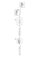
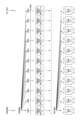
- FIG. 1 is a first diagram for explaining an overview of the training process of a reconstruction model.
- FIG. 2 is a first diagram for explaining an overview of an image generation process using a trained restoration model.
- FIG. 3 is a first diagram illustrating an example of a trained reconstruction model applied to a server device.
- FIG. 4 is a first diagram illustrating an example of a system configuration of a free viewpoint video playback system.
- FIG. 5 is a diagram illustrating an example of a hardware configuration of a server device and a client terminal.
- FIG. 6 is a first diagram illustrating an example of a functional configuration of a server device.
- FIG. 7 is a diagram illustrating an example of a trained restored model stored in the model storage unit of the server device according to the first embodiment.
- FIG. 1 is a first diagram for explaining an overview of the training process of a reconstruction model.
- FIG. 2 is a first diagram for explaining an overview of an image generation process using a trained restoration model.
- FIG. 3 is a first diagram
- FIG. 8A is a first diagram illustrating a specific example of processing by the server device according to the first embodiment.
- FIG. 8B is a second diagram illustrating a specific example of the process by the server device according to the first embodiment.
- FIG. 8C is a third diagram illustrating a specific example of processing by the server device according to the first embodiment.
- FIG. 8D is a fourth diagram illustrating a specific example of processing by the server device according to the first embodiment.
- FIG. 9 is a first diagram illustrating an example of a functional configuration of a client terminal.
- FIG. 10 is a diagram showing an example of a video designation screen of the client terminal.
- FIG. 11 is a first diagram illustrating an example of a video playback screen of a client terminal.
- FIG. 9 is a first diagram illustrating an example of a functional configuration of a client terminal.
- FIG. 10 is a diagram showing an example of a video designation screen of the client terminal.
- FIG. 11 is a first diagram illustrating an example of
- FIG. 19A is a first diagram illustrating a specific example of processing by a server device according to the second embodiment.
- FIG. 19B is a second diagram illustrating a specific example of processing by the server device according to the second embodiment.
- FIG. 20 is a third diagram for explaining an overview of the training process of the restoration model.
- FIG. 21 is a third diagram for explaining an overview of the image generation process using a trained restoration model.
- FIG. 22 is a third diagram illustrating an example of a trained reconstruction model applied to a server device.
- FIG. 23 is a diagram illustrating an example of a trained restored model stored in a model storage unit of a server device according to the third embodiment.
- FIG. 24A is a first diagram illustrating a specific example of processing by a server device according to the third embodiment.
- FIG. 24A is a first diagram illustrating a specific example of processing by a server device according to the third embodiment.
- FIG. 24B is a second diagram showing a specific example of processing by the server device according to the third embodiment.
- FIG. 25 is a fourth diagram for explaining an overview of the training process of the restoration model.
- FIG. 26 is a fourth diagram for explaining an overview of image generation processing using a trained restoration model.
- FIG. 27 is a fourth diagram showing an example of a trained reconstruction model applied to a server device.
- FIG. 28 is a diagram illustrating an example of a trained restored model stored in a model storage unit of a server device according to the fourth embodiment.
- FIG. 29A is a first diagram showing a specific example of processing by a server device according to the fourth embodiment.
- FIG. 29B is a second diagram showing a specific example of processing by the server device according to the fourth embodiment.
- FIG. 30 is a fifth diagram for explaining an overview of the training process of the restoration model.
- FIG. 31 is a fifth diagram for explaining an overview of image generation processing using a trained restoration model.
- FIG. 32 is a fifth diagram showing an example of a trained reconstruction model applied to a server device.
- FIG. 33 is a diagram illustrating an example of a trained restored model stored in a model storage unit of a server device according to the fifth embodiment.
- FIG. 34A is a first diagram showing a specific example of processing by a server device according to the fifth embodiment.
- FIG. 34B is a second diagram showing a specific example of processing by the server device according to the fifth embodiment.
- FIG. 35 is a second sequence diagram showing the flow of the free viewpoint video playback process by the free viewpoint video playback system.
- FIG. 35 is a second sequence diagram showing the flow of the free viewpoint video playback process by the free viewpoint video playback system.
- FIG. 36 is a second diagram showing an example of a system configuration of a free viewpoint video playback system.
- FIG. 37 is a second diagram illustrating an example of a functional configuration of the server device.
- FIG. 38 is a diagram illustrating an example of a trained restored model stored in a model storage unit of a server device according to the sixth embodiment.
- FIG. 39A is a first diagram showing a specific example of processing by a server device according to the sixth embodiment.
- FIG. 39B is a second diagram showing a specific example of processing by the server device according to the sixth embodiment.
- FIG. 39C is a third diagram showing a specific example of processing by the server device according to the sixth embodiment.
- FIG. 40 is a second diagram illustrating an example of the functional configuration of the client terminal.
- FIG. 40 is a second diagram illustrating an example of the functional configuration of the client terminal.
- FIG. 41 is a third sequence diagram showing the flow of free viewpoint video playback processing by the free viewpoint video playback system.
- FIG. 42 is a diagram illustrating an example of a trained restored model stored in a model storage unit of a server device according to the seventh embodiment.
- FIG. 43A is a first diagram showing a specific example of processing by a server device according to the seventh embodiment.
- FIG. 43B is a second diagram showing a specific example of processing by the server device according to the seventh embodiment.
- FIG. 44 is a fourth sequence diagram showing the flow of free viewpoint video playback processing by the free viewpoint video playback system.
- FIG. 45 is a diagram illustrating an example of a trained restored model stored in a model storage unit of a server device according to the eighth embodiment.
- FIG. 45 is a diagram illustrating an example of a trained restored model stored in a model storage unit of a server device according to the eighth embodiment.
- FIG. 46A is a first diagram showing a specific example of processing by a server device according to the eighth embodiment.
- FIG. 46B is a second diagram showing a specific example of processing by the server device according to the eighth embodiment.
- FIG. 47 is a fifth sequence diagram showing the flow of free viewpoint video playback processing by the free viewpoint video playback system.
- FIG. 48 is a diagram illustrating an example of a trained restored model stored in a model storage unit of a server device according to the ninth embodiment.
- FIG. 49A is a first diagram showing a specific example of processing by a server device according to the ninth embodiment.
- FIG. 49B is a second diagram showing a specific example of processing by the server device according to the ninth embodiment.
- FIG. 50 is a sixth sequence diagram showing the flow of free viewpoint video playback processing by the free viewpoint video playback system.
- FIG. 51 is a third diagram illustrating an example of a functional configuration of a server device.
- FIG. 52 is a third diagram illustrating an example of the functional configuration of a client terminal.
- FIG. 53 is a diagram showing an example of a trained restored model stored in a model storage unit of a server device according to the tenth embodiment.
- FIG. 54A is a first diagram showing a specific example of processing by a server device according to the tenth embodiment.
- FIG. 54B is a second diagram showing a specific example of processing by the server device according to the tenth embodiment.
- FIG. 55 is a seventh sequence diagram showing the flow of free viewpoint video playback processing by the free viewpoint video playback system.
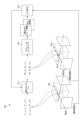
- FIG. 1 is a first diagram for explaining the overview of the training process of a reconstruction model.
- a restoration model 110 which is an example of a restoration model for restoring a three-dimensional scene, is a neural network (NN) to which the NeRF technique is applied, and is denoted as “F ⁇ ” in this embodiment.
- the restoration model 110 (F ⁇ ) has the following: Coordinate information (e.g., ( x1 , y1 , z1 )) specifying the coordinates of a 3D point in the 3D scene 140; and viewpoint information (e.g., viewpoint information ( ⁇ 1 , ⁇ 1 )) that specifies a direction vector representing a line of sight (e.g., Ray 1) from a viewpoint (e.g., viewpoint 1) to the three-dimensional point;
- the restored model 110 (F ⁇ ) is expressed as follows for the combination of the coordinate information of the input three-dimensional point and the viewpoint information:
- the color of the 3D point e.g., the color specified by ( R1 , G1 , B1 )
- the reconstruction model 110 (F ⁇ ) is subjected to a similar process for multiple viewpoints.
- the example in FIG. 1 shows a state in which the similar process is performed for two viewpoints (viewpoint 1 and view point 2).
- the reconstruction model 110 (F ⁇ ) further includes a 3D point in the 3D scene 140 (e.g., a point identified by ( x2 , y2 , z2 )); viewpoint information (e.g., viewpoint information ( ⁇ 2 , ⁇ 2 )) that specifies a direction vector representing a line of sight (e.g., Ray 2) from viewpoint 2 to the 3D point;
- viewpoint information e.g., viewpoint information ( ⁇ 2 , ⁇ 2 )
- a direction vector representing a line of sight e.g., Ray 2
- a volume rendering process 120 is performed for multiple combinations of color and opacity output from the restoration model 110 (F ⁇ ) for each of multiple 3D points on each line of sight.
- the volume rendering process 120 calculates the color of each pixel of an image seen from a certain viewpoint using a volume rendering method. Specifically, the volume rendering process 120 calculates the color of each pixel by performing volume rendering using a predetermined product-sum operation based on the color and opacity output from the restoration model 110 (F ⁇ ) for each of a plurality of three-dimensional points on the line of sight connecting the pixel and the viewpoint. As a result, the volume rendering process 120 generates a view image of a certain viewpoint.
- the view image refers to an image of a scene seen from a specific viewpoint (i.e., an image based on specific viewpoint information) among free viewpoint images, which are images of a scene seen from various viewpoints (i.e., images based on various viewpoint information).
- a loss calculation process 130 is performed on each of the generated view images from viewpoint 1 and viewpoint 2.
- the view image from viewpoint 1 is compared with captured image A captured by the imaging device at viewpoint 1 to calculate an error.
- the view image from viewpoint 2 is compared with captured image B captured by the imaging device at viewpoint 2 to calculate an error.
- the error calculated in the loss calculation process 130 is backpropagated through the restoration model 110 (F ⁇ ) by the error backpropagation method in the update process of the restoration model 110 (F ⁇ ).
- a trained restoration model (F ⁇ ) is generated according to the training process 100 shown in FIG. 1 .
- FIG. 2 is a first diagram for explaining the overview of the image generation process using the trained restoration model.
- the image generation process for generating a view image of viewpoint ij inputs 3D points ( xn , yn , zn ) and viewpoint information ( ⁇ i , ⁇ j ) related to viewpoint ij into a trained restoration model 210 ( F ⁇ ), and calculates the color and opacity of each 3D point as its output. Then, the image generation process generates the view image of viewpoint ij by performing a volume rendering process 120 based on the calculated color and opacity of each 3D point for each pixel of the view image.
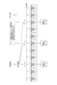
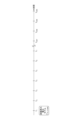
- FIG. 3 is a first diagram showing an example of a trained restoration model applied to the server device. Note that, in Fig. 3, for the sake of simplicity, a case in which two viewpoints, viewpoint 1 and viewpoint 2, are used is shown, but as described above, in the training process, images captured by an imaging device at viewpoints other than viewpoint 1 and viewpoint 2 may be used.
- the server device includes: A captured image A1 captured by an imaging device at a viewpoint 1 at time information T1 ; A captured image B1 captured by an imaging device at a viewpoint 2 at time information T1 ; A trained reconstruction model (F ⁇ 1 ) that has been trained using is applied.
- the server device includes: A captured image A2 captured by an imaging device at a viewpoint 1 at time information T2 ; and A captured image B2 captured by an imaging device at a viewpoint 2 at time information T2 ; and A trained reconstruction model (F ⁇ 2 ) that has been trained using is applied.
- the time information T1 , T2 , T3 , ... corresponds to the frame period (an example of a first time interval, for example, 30 fps) of the captured images A1 , A2 , ... or the captured images B1 , B2 , ... captured by the imaging device during the training process.
- a trained restoration model an example of a first restoration model of a time series of a frame period is applied to the server device to generate a time series of view images of the frame period.
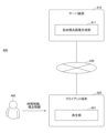
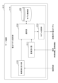
- Fig. 4 is a first diagram showing an example of a system configuration of the free viewpoint video playback system.
- the free viewpoint video playback system 400 includes a server device 410 according to the first embodiment and a client terminal 420.
- the server device 410 and the client terminal 420 are communicatively connected via a communication network 430.
- a free viewpoint image generation program is installed in the server device 410, and by executing this program, the server device 410 functions as a free viewpoint image generation unit 411.
- the free viewpoint image generation unit 411 receives a request from the client terminal 420 via the communication network 430, and reads and executes a trained restoration model held in the model storage unit 606 (described later) based on the time information and viewpoint information contained in the received request.
- the free viewpoint image generation unit 411 transmits the view image at each time information generated by executing the trained restoration model corresponding to each time information in a transmission format that allows video playback.
- a playback program is installed in the client terminal 420, and by executing the program, the client terminal 420 functions as a playback unit 421.
- the playback program may be a dedicated application or a specified browser.
- the playback unit 421 transmits a request including the time information and viewpoint information input by the user 440 to the server device 410 via the communication network 430.
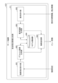
- the server device 410 has as its components a processor 501, a main storage device 502 (memory), an auxiliary storage device 503 (memory), a network interface 504, and a device interface 505.
- the server device 410 may be realized as a computer in which these components are connected via a bus 506. Note that, although the example of FIG. 5 shows the server device 410 as having one of each component, the server device 410 may have multiple of the same component.
- the various calculations of the server device 410 may be executed in parallel using one or more processors. Furthermore, the various calculations may be distributed to multiple calculation cores in the processor 501 and executed in parallel. Furthermore, some or all of the processes, means, etc. disclosed herein may be executed by an external device 510 (at least one of a processor and a storage device) provided on a cloud that can communicate with the server device 410 via the network interface 504.
- an external device 510 at least one of a processor and a storage device
- the processor 501 may be an electronic circuit (processing circuit, processing circuitry, CPU, GPU, FPGA, ASIC, etc.).
- the processor 501 may also be a semiconductor device including a dedicated processing circuit.
- the processor 501 is not limited to an electronic circuit using electronic logic elements, and may be realized by an optical circuit using optical logic elements.
- the processor 501 may also include a calculation function based on quantum computing.
- the processor 501 performs various calculations based on various data and commands input from each device in the internal configuration of the server device 410, and outputs the calculation results and control signals to each device.
- the processor 501 controls each component of the server device 410 by executing the OS (Operating System), applications, etc.
- the processor 501 may refer to one or more electronic circuits arranged on one chip, or to one or more electronic circuits arranged on two or more chips or devices. When multiple electronic circuits are used, each electronic circuit may communicate by wire or wirelessly.
- the network interface 504 is an interface for connecting to the communication network 430 wirelessly or via a wired connection.
- the device interface 505 is an interface such as a USB that directly connects to an external device 520.
- the external device 520 may be, for example, an input device.
- the input device is, for example, a keyboard, a mouse, a touch panel, or other device, and provides the acquired information to the server device 410.
- the external device 520 may be, as an example, an output device.
- the output device may be, for example, a display device such as an LCD (Liquid Crystal Display), a CRT (Cathode Ray Tube), a PDP (Plasma Display Panel), or an organic EL (Electro Luminescence) panel, or may be a speaker that outputs sound, etc.
- the external device 520 may also be a storage device (memory).
- the external device 520 may be a network storage device, or the external device 520 may be a storage device such as a HDD.
- Fig. 6 is a first diagram showing an example of the functional configuration of the server device.
- the server device 410 functions as a free viewpoint image generating unit 411.
- the free viewpoint image generating unit 411 further includes a video designation receiving unit 601, a default video generating unit 602, a request receiving unit 603, a requested video generating unit 604, and a video transmitting unit 605.
- the default video generation unit 602 reads out from the model storage unit 606 a group of trained restoration models for generating view images included in the free viewpoint video identified by the identification information notified by the video specification reception unit 601.
- the default video generating unit 602 also inputs default viewpoint information to the group of trained restoration models that have been read out, and generates view images for each time (each time instant) according to the default viewpoint information.
- the view images according to the default viewpoint information generated by the default video generating unit 602 are notified to the video transmitting unit 605.
- the request receiving unit 603 receives a request from the client terminal 420.
- the request sent from the client terminal 420 includes time information and viewpoint information.
- the request received by the request receiving unit 603 is notified to the requested video generating unit 604.
- the requested video generating unit 604 performs processing according to the type of time information included in the request notified by the request receiving unit 603. For example, assume that the time information included in the request is time information based on a playback instruction in the client terminal 420. This time information may be, for example, the time when the user 440 issues a playback instruction for the video, regardless of whether playback is in progress or stopped in the client terminal 420.
- the requested video generating unit 604 sequentially inputs the viewpoint information included in the request to the trained restoration model that corresponds to the time information notified by the request receiving unit 603, among the trained restoration models that have already been read out. As a result, the requested video generating unit 604 sequentially generates view images according to the time information and viewpoint information included in the request, and notifies the video sending unit 605.
- the time information included in the request is time information based on a stop instruction in the client terminal 420 (an example of time information according to a termination condition).
- This time information may be, for example, the time when the user 440 issues an instruction to stop playback of the video being played on the client terminal 420.
- the requested video generating unit 604 identifies the trained restoration model that corresponds to the time information notified by the request receiving unit 603 from among the trained restoration models that have already been read out as the last trained restoration model being played, and inputs the viewpoint information included in the request.
- the requested video generating unit 604 then generates a last view image according to the time information and viewpoint information included in the request, notifies the video sending unit 605, and stops processing.
- the time information included in the request is time information based on an operational instruction during pause on the client terminal 420.
- This time information may be, for example, a time based on an operational instruction (for example, an operational instruction on a seek bar indicator, which will be described later) given by the user 440 to a scene to be displayed while the video is paused on the client terminal 420.
- each time time information is notified by the request receiving unit 603, the requested video generating unit 604 generates a view image by inputting the viewpoint information included in the request into the trained restoration model corresponding to the time information, and notifies the video transmitting unit 605.
- the video transmission unit 605 transmits a view image according to the default viewpoint information notified by the default video generation unit 602 in a transmission format that allows video playback on the client terminal 420.
- the video transmission unit 605 also transmits a view image according to the time information and viewpoint information included in the request notified by the requested video generation unit 604 in a transmission format that allows video playback on the client terminal 420.
- transmitting in a transmission format that allows video playback includes, for example, transmitting the view image as is to the client terminal 420. Also, transmitting in a transmission format that allows video playback includes, for example, performing video encoding processing on the view image and then transmitting it to the client terminal 420. Also, the encoding method when performing video encoding processing on the view image and then transmitting it to the client terminal 420 is arbitrary, and for example, video encoding processing may be performed by H.264/MPEG4. Also, when performing video encoding processing on the view image and then transmitting it to the client terminal 420, the view image that has been subjected to video encoding processing is restored by the client terminal 420. As a result, a free viewpoint video is played in the client terminal 420 with the restored view image as a frame image.
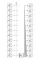
- Fig. 7 is a diagram showing an example of a trained restoration model stored in the model storage unit of the server device according to the first embodiment.
- the trained restoration model held by the model storage unit 606 is associated with time information.
- the trained restoration model F ⁇ 1 is associated with the time information T 1
- the trained restoration model F ⁇ 2 is associated with the time information T 2.
- the example of Fig. 7 shows that the trained restoration models F ⁇ 3 to F ⁇ 11 are associated with the time information T 3 to T 11 , respectively.
- the association between the time information and the trained restoration model may be performed by directly associating the time information with the trained restoration model, or may be performed by indirectly associating the time information with the trained restoration model via other data.
- the server device 410 uses the trained restoration model stored in the model storage unit 606 to generate time-series view images according to the viewpoint information and time information included in the request received from the client terminal 420.
- the time information T1 , T2 , T3 , ... corresponds to the frame period of the captured image captured by the imaging device during the training process, as described above. Therefore, the time information T1 , T2 , T3 , ... corresponds to the frame period when the free viewpoint video is played back in the free viewpoint video playback system 400.
- the trained restoration models associated with each piece of time information are different from each other.
- the different trained restoration models referred to here are composed of NNs to which NeRF technology is applied, and are trained using different training data (captured images).
- the NN architecture may be the same or may have some different parts.
- each trained restoration model shown in Figure 7 can generate a view image from any viewpoint (free viewpoint image) for the scene at each time point.
- the model storage unit 606 holds at least a set of trained restoration models for generating view images for a series of scenes for one target.
- the set of trained restoration models held by the model storage unit 606 is not limited to one, and the model storage unit 606 may hold another set of trained restoration models for generating view images for a series of scenes for another target.
- the group of trained restoration models held by the model storage unit 606 includes 11 trained restoration models with time information T 1 to T 11 due to space limitations.
- the number of trained restoration models included in the group of trained restoration models held by the model storage unit 606 is not limited to this.
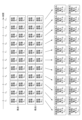
- Fig. 8A is a first diagram showing a specific example of processing by the server device according to the first embodiment.
- Fig. 8A shows a specific example of processing when the video designation receiving unit 601 accepts designation of a free viewpoint video and the default video generating unit 602 receives a notification of identification information of the designated free viewpoint video from the video designation receiving unit 601.
- the default video generation unit 602 reads out trained restoration models F ⁇ 1 to F ⁇ 11 for generating view images included in the specified free viewpoint video from the model storage unit 606.
- the default video generator 602 also inputs default viewpoint information ( ⁇ 0 , ⁇ 0 ) to each of the trained restoration models F ⁇ 1 to F ⁇ 11 that have been read out.
- the trained restoration models F ⁇ 1 to F ⁇ 11 generate view images X 1 to X 11 at each time information of the scene viewed from a viewpoint based on the default viewpoint information ( ⁇ 0 , ⁇ 0 ).
- default video generation unit 602 associates the generated view images X1 to X11 with time information T1 to T11 and notifies video transmission unit 605.
- video transmission unit 605 transmits view images X1 to X11 in a transmission format that allows video playback on client terminal 420.
- FIG. 8B is a second diagram showing a specific example of processing by the server device according to the first embodiment, and shows a specific example of processing by the requested video generating unit 604 when a request is notified from the request receiving unit 603.
- the requested video generation unit 604 identifies the trained restoration model F ⁇ 3 that corresponds to the time information included in the request (T 3 in the example of FIG. 8B) from among the trained restoration models F ⁇ 1 to F ⁇ 11 that have already been read out.
- the requested video generator 604 inputs the viewpoint information included in the request (( ⁇ x , ⁇ x ) in the example of FIG. 8B ) to the identified trained restoration model F ⁇ 3 .
- the trained restoration model F ⁇ 3 generates a view image X3 at time information T3 of the scene viewed from a viewpoint based on the viewpoint information ( ⁇ x , ⁇ x ) included in the request.
- the request video generator 604 specifies a trained restoration model F ⁇ 4 corresponding to the next time information (next time) as the next trained restoration model.
- the request video generator 604 also inputs viewpoint information included in the request (( ⁇ x , ⁇ x ) in the example of FIG. 8B ) to the specified trained restoration model F ⁇ 4 .
- the trained restoration model F ⁇ 4 generates a view image X 4 at time information T 4 of the scene viewed from a viewpoint based on the viewpoint information ( ⁇ x , ⁇ x ) included in the request.
- Fig. 8B shows a state in which time information T10 is transmitted from the client terminal 420 as the end condition.
- the requested video generating unit 604 identifies a trained restoration model F ⁇ 10 corresponding to the time information T10 transmitted as the termination condition as the last trained restoration model.
- the requested video generating unit 604 also inputs viewpoint information included in the request (( ⁇ x , ⁇ x ) in the example of FIG. 8B ) to the identified trained restoration model F ⁇ 10 .
- the trained restoration model F ⁇ 10 generates a view image X10 at the time information T10 of the scene viewed from a viewpoint based on the viewpoint information ( ⁇ x , ⁇ x ) included in the request.
- the requested video generating unit 604 generates a time-series view image according to the viewpoint information using a time-series trained restoration model ranging from a trained restoration model corresponding to the time information included in the request to a trained restoration model corresponding to a specified termination condition.
- the end condition here refers to time information based on a stop instruction to stop playback of the free viewpoint video in response to a request.
- the client terminal 420 transmits time information corresponding to the timing of the press to the server device 410 as the end condition.
- the end condition transmitted by the client terminal 420 is not limited to this. For example, when playing back a free viewpoint video, if a time range is specified and the client terminal 420 receives the specification, the client terminal 420 transmits time information corresponding to the end timing of the time range to the server device 410 as the end condition.
- the termination condition is not necessarily transmitted by the client terminal 420.
- the trained restoration model corresponding to the last time information among the trained restoration models in the time series becomes the trained restoration model corresponding to the specified termination condition.
- Requested video generation unit 604 associates the generated view images X3 to X10 with time information T3 to T10 and sequentially notifies video transmission unit 605. This allows video transmission unit 605 to transmit view images X3 to X10 in a transmission format that allows video playback on client terminal 420.
- FIG. 8C is a third diagram showing a specific example of processing by the server device according to the first embodiment, and shows a specific example of processing by the requested video generating unit 604 when a request is notified from the request receiving unit 603.
- the requested video generation unit 604 identifies the trained restoration model F ⁇ 1 that corresponds to the time information included in the request (T 1 in the example of FIG. 8C ) from among the trained restoration models F ⁇ 1 to F ⁇ 11 that have already been read out from the model storage unit 606.
- the requested video generator 604 inputs viewpoint information to the identified trained restoration model F ⁇ 1 .
- viewpoint information since viewpoint information is not included in the request, the requested video generator 604 inputs viewpoint information included in the most recent request (( ⁇ x , ⁇ x ) in the example of Fig. 8C).
- the trained restoration model ⁇ 1 generates a view image X 1 at time information T 1 of the scene seen from a viewpoint based on the current viewpoint information ( ⁇ x , ⁇ x ).
- the requested video generating unit 604 specifies a trained restoration model F ⁇ 2 corresponding to the next time information (next time) as the next trained restoration model.
- the requested video generating unit 604 also inputs viewpoint information (( ⁇ x , ⁇ x ) in the example of FIG. 8C ) included in the most recent request to the specified trained restoration model F ⁇ 2 .
- the trained restoration model ⁇ 2 generates a view image X 2 at time information T 2 of the scene viewed from a viewpoint based on the current viewpoint information ( ⁇ x , ⁇ x ).
- Fig. 8C shows a state in which time information T10 is transmitted from the client terminal 420 as the end condition.
- the requested video generating unit 604 identifies a trained restoration model F ⁇ 10 corresponding to the time information T10 transmitted as the termination condition as the last trained restoration model.
- the requested video generating unit 604 also inputs current viewpoint information (( ⁇ x , ⁇ x ) in the example of FIG. 8C ) to the identified trained restoration model F ⁇ 10 .
- the trained restoration model ⁇ 10 generates a view image X10 at time information T10 of the scene viewed from a viewpoint based on the current viewpoint information ( ⁇ x , ⁇ x ).
- Requested video generation unit 604 associates the generated view images X 1 to X 10 with time information T 1 to T 10 and sequentially notifies video transmission unit 605. This allows video transmission unit 605 to transmit view images X 1 to X 10 according to the time information and current viewpoint information ( ⁇ x , ⁇ x ) included in the request in a transmission format that allows video playback on client terminal 420.
- the free viewpoint video playback system 400 it is not always possible to play back all view images generated by the identified trained restoration model as frame images on the client terminal 420.
- the frame period in the client terminal 420 is longer than the time interval at which the view image is generated by the requested moving image generating unit 604
- the display mode on the client terminal 420 is the double speed mode or the 10-second skip mode
- the communication load between the server device 410 and the client terminal 420 is high and the communication speed is slowing down
- the processing load of the server device 410 or the client terminal 420 is increasing, etc., not all view images can necessarily be played back as frame images on the client terminal 420.
- Fig. 8D is a fourth diagram showing a specific example of processing by the server device according to the first embodiment.
- the requested video generation unit 604 identifies the trained restoration model F ⁇ 3 that corresponds to the time information included in the request (T 3 in the example of FIG. 8D ) from among the trained restoration models F ⁇ 1 to F ⁇ 11 that have already been read out from the model storage unit 606.
- the requested video generator 604 inputs the viewpoint information included in the request (( ⁇ x , ⁇ x ) in the example of FIG. 8D ) to the identified trained restoration model F ⁇ 3 .
- the trained restoration model ⁇ 3 generates a view image X3 at time information T3 of the scene viewed from a viewpoint based on the viewpoint information ( ⁇ x , ⁇ x ) included in the request.
- the requested video generation unit 604 determines the timing of generating a view image when identifying the next trained restoration model. - Frame period at the client terminal 420, - Display mode in the client terminal 420, The communication load between the server device 410 and the client terminal 420, The processing load of the server device 410 and the client terminal 420, and determines the generation timing of the view image based on the obtained information.
- the example of Fig. 8D also shows the requested video generator 604 inputting viewpoint information included in the request (( ⁇ x , ⁇ x ) in the example of Fig. 8D ) to the specified trained restoration model F ⁇ 6 .
- the trained restoration model ⁇ 6 generates a view image X6 at time information T6 of the scene seen from a viewpoint based on the viewpoint information ( ⁇ x , ⁇ x ) included in the request.
- the requested video generating unit 604 thereafter repeats the same process (thinning process) until an end condition is transmitted from the client terminal 420.
- the example of Fig. 8D illustrates a state in which time information T10 is transmitted from the client terminal 420 as the end condition.
- requested moving image generator 604 determines that it is not time to generate a view image, and stops processing without generating view image X10 .
- Requested video generating unit 604 associates the generated view images X3 , X6 , and X9 with time information T3 , T6 , and T9 , and sequentially notifies video transmitting unit 605. This enables video transmitting unit 605 to transmit view images X3 , X6 , and X9 in a transmission format that allows client terminal 420 to play the view images.
- Fig. 9 is a first diagram showing an example of the functional configuration of the client terminal.
- the client terminal 420 functions as a playback unit 421.
- the playback unit 421 further includes a video designation transmission unit 901, a video reception unit 902, a video playback unit 903, a video display unit 904, and a request transmission unit 905.
- the video designation transmission unit 901 receives a designation for a free viewpoint video from the user 440 via a video designation screen (details of which will be described later).
- the video designation transmission unit 901 transmits, to the server device 410, identification information for uniquely identifying the free viewpoint video for which the designation has been received.
- the video receiving unit 902 receives a view image transmitted from the server device 410 and notifies the video playback unit 903. Alternatively, the video receiving unit 902 receives a view image that has been subjected to video encoding processing and is transmitted from the server device 410, restores the view image that has been subjected to video encoding processing, and notifies the video playback unit 903.
- the video playback unit 903 notifies the video display unit 904 of the notified view image at a predetermined frame rate.
- the video display unit 904 plays a free viewpoint video on a video playback screen (details will be described later) in which the notified view images are used as frame images at a predetermined frame cycle.
- the video display unit 904 also accepts requests (either one or both of time information and viewpoint information) from the user 440 on the played video playback screen, and notifies the request transmission unit 905.
- the time information included in the request notified to the request transmission unit 905 includes the following: - Time information based on a playback instruction, - Time information based on the stop instruction, - Time information based on various operations during stop etc. are included.
- the request sending unit 905 sends the request (time information, viewpoint information) notified by the video display unit 904 to the server device 410.
- a list of free viewpoint videos that can be provided by the server device 410 is displayed on a video selection screen 1000 of the client terminal 420.
- the example in FIG. 10 shows four free viewpoint videos displayed as free viewpoint videos that can be provided by the server device 410.
- the user 440 selects a free viewpoint video to be played from among the free viewpoint videos displayed on the video selection screen 1000.
- the video selection transmission unit 901 transmits, to the server device 410, identification information for uniquely identifying the selected free viewpoint video.
- the example in FIG. 10 shows how "Video I" has been selected as a free viewpoint video by the user 440.
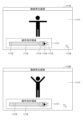
- FIG. 11 is a first diagram showing an example of a display screen of a client terminal.
- the video playback screen of the client terminal 420 switches to a video playback screen 1110, and the free viewpoint video of "video I" is played.
- the video playback screen includes a video display area 1117 and an operation instruction area 1111.
- the operation instruction area 1111 includes: ⁇ Seek bar 1112, Stop button 1113, Play button 1114, ⁇ 10 second skip button 1115 etc. are included.
- the seek bar 1112 is a bar that uses an indicator 1112' to indicate the current playback position of the free viewpoint video being played in the video display area 1117.
- the indicator 1112' of the seek bar 1112 moves from the left to the right on the paper in conjunction with the passage of time in the video during playback of the free viewpoint video.
- the user 440 can use the mouse pointer 1116 to move the indicator 1112' to the left or right on the paper.
- moving the indicator 1112' is equivalent to sending a request including the time information of the destination to the server device 410.
- the stop button 1113 stops the playback of the free viewpoint video.
- pressing the stop button 1113 is equivalent to inputting an end condition to the server device 410.
- pressing the play button 1114 is equivalent to sending a request including time information of the current stop position to the server device 410.
- the 10-second skip button 1115 is a button that, when pressed by the user 440 while a free viewpoint video is being played, moves the current playback position (the position of the current indicator 1112') to a playback position 10 seconds ahead or 10 seconds back.
- pressing the 10-second skip button is equivalent to sending a request to the server device 410 that includes time information for the playback position 10 seconds ahead or 10 seconds back from the current playback position.
- video playback screen 1120 shows the display screen after a predetermined time has elapsed since video playback screen 1110 was displayed. As the predetermined time has elapsed, the movement of the subject contained in video display area 1117 of video playback screen 1120 has changed from the movement of the subject contained in video display area 1117 of video playback screen 1110. In addition, the position of indicator 1112' in operation instruction area 1111 of video playback screen 1110 has moved to the right on the page in video playback screen 1120.
- Video playback screen 2 Next, another specific example of the video playback screen will be described.
- the user 440 presses the stop button 1113, and in a state in which the playback of the free viewpoint video of "video 1" is stopped, the user 440 further presses Time information is input by moving the indicator 1112' of the seek bar 1112 in the operation instruction area 1111.
- the viewpoint information is input by dragging the moving image display area 1117 with the mouse pointer 1116.
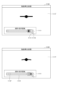
- 12 is a second diagram showing an example of the video playback screen of the client terminal.
- the video playback screen 1130 shows that after the video playback screen 1120 is displayed, the stop button 1113 is pressed to stop playback, and the position of the indicator 1112' is moved to the left on the page by the mouse pointer 1116.
- a frame image corresponding to the time information of the position of indicator 1112' is displayed in video display area 1117 of video playback screen 1130. Since the viewpoint information has not changed here, a frame image is displayed in which the same subject's movements as those included in video display area 1117 of video playback screen 1110 are viewed from the same viewpoint.
- the video playback screen 1140 shows how, after the video playback screen 1130 is displayed, the video display area 1117 is dragged downward with the mouse pointer 1116, causing the viewpoint to rotate upward.
- video playback screen 1140 As shown in video playback screen 1140, by rotating the viewpoint upward, the viewpoint with respect to the subject contained in video display area 1117 moves, and frame images of the scene viewed from above are displayed. Since the time information has not been changed here, video display area 1117 of video playback screen 1140 displays frame images of the scene viewed from above, showing the same movements as those of the subject contained in video display area 1117 of video playback screen 1130.
- the video display area 1117 is shown being dragged downward by the mouse pointer 1116, but the direction in which the video display area 1117 is dragged is not limited to downward, and it can be dragged in any direction.
- video display area 1117 on video playback screen 1140 will display a frame image of a scene seen from the right side, showing the same movement as that of the subject included in video display area 1117 on video playback screen 1130.
- video display area 1117 on video playback screen 1140 will display a frame image of a scene seen from the left side, showing the same movement as that of the subject included in video display area 1117 on video playback screen 1130.
- the server device 410 in response to the above operation on the client terminal 420, the server device 410 generates a view image according to the viewpoint information using a trained restoration model corresponding to the changed time information, for example, each time the time information is changed by the client terminal 420. Also, in the server device 410, each time the viewpoint information is changed by the client terminal 420, a view image according to the changed viewpoint information in the current time information is generated.
- FIG. 13 is a third diagram showing an example of the video playback screen of the client terminal.
- video playback screen 1150 shows a state in which play button 1114 has been pressed by user 440 after video playback screen 1140 has been displayed. As shown in video playback screen 1150, pressing play button 1114 with mouse pointer 1116 causes free viewpoint video of "video 1" to be played from the current time information based on the input viewpoint information.
- video playback screen 1160 shows the state after a predetermined time has passed since play button 1114 was pressed on video playback screen 1150.
- the predetermined time has passed, the movement of the subject contained in video display area 1117 of video playback screen 1160 has changed from the movement of the subject contained in video display area 1117 of video playback screen 1150.
- the position of indicator 1112' in operation instruction area 1111 of video playback screen 1160 has moved further to the right on the page than the position of indicator 1112' in operation instruction area 1111 of video playback screen 1150.
- the video display area 1117 of the video playback screen 1160 displays frame images of a scene viewed from above, showing the same movement as that of the subject included in the video display area 1117 of the video playback screen 1120.
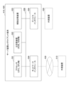
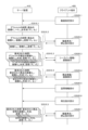
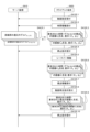
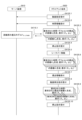
- FIG. 14 is a first sequence diagram showing the flow of free viewpoint video playback processing by the free viewpoint video playback system.
- step S1420_1 the client terminal 420 accepts a designation from the user 440 regarding the free viewpoint video to be displayed, and transmits identification information for uniquely identifying the designated free viewpoint video to the server device 410.
- step S1410_1 the server device 410 reads out a group of trained restoration models for generating view images included in the specified free viewpoint video.
- the server device 410 also inputs default viewpoint information ( ⁇ 0 , ⁇ 0 ) into the group of trained restoration models that have been read out, thereby generating view images X 1 to X 11 .
- step S1410_2 the server device 410 sequentially transmits the generated view images to the client terminal 420.
- step S1420_2 the client terminal 420 plays the free viewpoint video in which the view images transmitted from the server device 410 are used as frame images.
- the client terminal 420 also receives an instruction to stop the free viewpoint video being played back, and transmits it to the server device 410. As a result, the server device 410 stops transmitting the view images.
- step S1420_3 the client terminal 420 receives an instruction to move the indicator 1112' on the seek bar 1112.
- the client terminal 420 sequentially transmits time information for each position of the moving indicator 1112' to the server device 410.
- step S1410_3 each time the server device 410 receives time information for each position of the moving indicator 1112' from the client terminal 420, the server device 410 inputs default viewpoint information into the trained restoration model corresponding to the time information for each position. As a result, the server device 410 generates a view image according to the time information for each position. In addition, the server device 410 sequentially transmits the generated view images to the client terminal 420. As a result, the client terminal 420 displays a view image corresponding to the time information for each position of the moving indicator 1112'.
- step S1420_4 when the video display area is dragged by the mouse pointer 1116, the client terminal 420 accepts this.
- the client terminal 420 transmits viewpoint information for each position of the moving mouse pointer 1116 to the server device 410.
- step S1410_4 each time the server device 410 receives viewpoint information for each position of the moving mouse pointer 1116 from the client terminal 420, the server device 410 inputs the viewpoint information for each position into the trained restoration model corresponding to the current time information. As a result, the server device 410 generates a view image according to the viewpoint information for each position. In addition, the server device 410 sequentially transmits the generated view images to the client terminal 420. As a result, view images corresponding to the viewpoint information for each position of the moving mouse pointer 1116 are displayed on the client terminal 420.
- step S1420_5 when the play button 1114 is pressed, the client terminal 420 sends a play instruction to the server device 410.
- step S1410_5 the server device 410 generates a view image by inputting the current viewpoint information into a trained restoration model corresponding to the current time information, and transmits the view image to the client terminal 420.
- the server device 410 generates a view image by inputting the current viewpoint information into a trained restoration model corresponding to the next time information, and transmits the view image to the client terminal 420.
- the server device 410 repeats the same process until an end condition is transmitted from the client terminal 420.
- step S1420_6 the client terminal 420 plays back the free viewpoint video in which the view images transmitted from the server device 410 are used as frame images.
- the client terminal 420 also accepts an instruction to stop the free viewpoint video being played back, and transmits it to the server device 410.
- the server device 410 stops generating and transmitting the view images.
- the server device 410 includes one or more memories and one or more processors. - Holding one or more trained restoration models (first restoration models) that have been trained in advance to restore a scene from a first time to a second time using time-series captured images from multiple viewpoints obtained by capturing a scene from each of multiple viewpoints in a time series.
- the one or more trained restoration models (first restoration models) are trained restoration models for a time series of a first time interval that generate time-series view images for a first time interval. More specifically, the one or more trained restoration models (first restoration models) are trained restoration models that correspond one-to-one to different time information, and are a plurality of trained restoration models trained to output information of images at the corresponding time information.
- the one or more processors - Receive a request from a client terminal, the request including viewpoint information and time information for the scene.
- Using one or more trained restoration models generate time-series view images according to viewpoint information and time information included in the request received from the client terminal, and transmit them in a transmission format that allows video playback on the client terminal. More specifically, generate time-series view images of the first time interval according to viewpoint information included in the request using a trained restoration model (first restoration model) of a first time interval from a trained restoration model (first restoration model) corresponding to the time information included in the request to a trained restoration model (first restoration model) corresponding to a predetermined termination condition.
- a mechanism for playing free viewpoint video can be constructed.
- the model storage unit 606 holds one trained restoration model for each piece of time information, and one trained restoration model generates a view image at one piece of time information.
- the trained restoration model is not limited to this, and the model storage unit 606 may hold trained restoration models capable of generating view images at a plurality of pieces of continuous time information.
- the second embodiment will be described, focusing on the differences from the first embodiment.
- FIG. 15 is a second diagram for explaining the overview of the training process of the restoration model.
- the difference from the training process 100 described with reference to FIG. 1 in the first embodiment is that in the case of the training process 1500 shown in FIG.
- Coordinate information e.g., ( x1 , y1 , z1 )
- viewpoint information e.g., viewpoint information ( ⁇ 1 , ⁇ 1 )
- - time information specifying the time of the 3D scene
- the restored model 110 (F ⁇ ) is expressed as follows for the combination of the input coordinate information, viewpoint information, and time information:
- the color of the 3D point for example, the color specified by (R 11 , G 11 , B 11 )
- the opacity of the 3D point e.g., the opacity specified by ⁇ 11
- the restored model 110 calculates the color and opacity of a certain 3D point at a certain viewpoint and at a certain time.
- the coordinate information, viewpoint information, and time information of the 3D point may be referred to as the 3D point, viewpoint, and time (or time instant), respectively.
- the same processing is performed for a plurality of viewpoints on the restored model 110 (F ⁇ ) in the training process 1500.
- the example of Fig. 15 shows how the same processing is performed for two viewpoints (viewpoint 1 and viewpoint 2).
- viewpoint information e.g., viewpoint information ( ⁇ 2 , ⁇ 2 )
- - time information specifying the time of the 3D scene
- the restored model 110 (F ⁇ ) is calculated as follows for the combination of the input 3D points, viewpoint information, and time information:
- the color of the 3D point e.g., the color specified by (R 21 , G 21 , B 21 )
- the opacity of the 3D point e.g., the opacity specified by ⁇ 21
- the combinations are output in sequence.
- a volume rendering process 120 is performed on the combinations of color and opacity of the 3D points sequentially output from the restoration model 110 (F ⁇ ) for each of the multiple 3D points on each line of sight.
- the volume rendering process 120 calculates the color of each pixel of an image seen from a certain viewpoint at a certain time by using a volume rendering method. Specifically, the volume rendering process 120 calculates the color of each pixel at a certain time by performing volume rendering using a predetermined product-sum operation based on the color and opacity output from the restoration model 110 (F ⁇ ) for each of multiple three-dimensional points on the line of sight connecting the pixel and the viewpoint. As a result, the volume rendering process 120 generates a view image of a certain viewpoint at a certain time.
- the example of FIG. 15 shows how the view images (view images 11 to 13 of viewpoint 1) at each time information of viewpoint 1 and the view images (view images 21 to 23 of viewpoint 2) at each time information of viewpoint 2 are generated by the volume rendering process 120.
- a loss calculation process 130 is performed on the view images (view images 11 to 13 from viewpoint 1, and view images 21 to 23 from viewpoint 2) at each time information of each generated viewpoint.
- view images at each time information of viewpoint 1 are compared with captured images at each time information captured by the imaging device of viewpoint 1 (captured images A1 to A3 ) to calculate an error.
- view images at each time information of viewpoint 2 are compared with captured images at each time information captured by the imaging device of viewpoint 2 (captured images B1 to B3 ) to calculate an error.
- the error calculated in the loss calculation process 130 is backpropagated through the restoration model 110 (F ⁇ ) by the error backpropagation method in the update process of the restoration model 110 (F ⁇ ).
- a trained restoration model (F ⁇ ) is generated according to the training process 1500 shown in FIG. 15 .
- Fig. 16 is a second diagram for explaining the overview of an image generation process using a trained restoration model.
- FIG. 17 is a second diagram showing an example of a trained restoration model applied to the server device. Note that, in Fig. 17, for the sake of simplicity, a case in which two viewpoints, viewpoint 1 and viewpoint 2, are used is shown, but as described above, in the training process, images captured by an imaging device at viewpoints other than viewpoint 1 and viewpoint 2 may be used.
- the server device 410 includes: A set of pre-trained reconstruction models that are pre-trained to reconstruct a scene from a first time to a second time using a time series of captured images obtained by capturing the scene successively from multiple viewpoints; applies.
- the server device 410 includes: Images A1 to A3 captured by an imaging device at a viewpoint 1 at time information T1 to time information T3 ; Images B1 to B3 captured by an imaging device at viewpoint 2 at time information T1 to T3 ; A trained restoration model F ⁇ 1 - ⁇ 3 , which has been trained using
- the server device 410 has Images A4 to A6 captured by the imaging device at viewpoint 1 at time information T4 to T6 , Images B4 to B6 captured by the imaging device at viewpoint 2 at time information T4 to T6 , A trained restoration model F ⁇ 4_ ⁇ 6 , which has been trained using
- the trained restoration model F ⁇ 10- ⁇ 12 of the time information T 11 is shown, but the number of trained restoration models applied to the server device 410 is not limited to four. However, each trained restoration model is associated with each piece of time information and is managed as a time-series trained restoration model.
- the time information T1 , T4 , T7 , ... corresponds to a second time interval longer than the frame period (an example of a first time interval) of the captured images A1 , A2 , ... or the captured images B1 , B2 , ... captured by the imaging device during the training process.
- a trained restoration model for generating a time series view image of the first time interval which is a time series trained restoration model of the second time interval (an example of a second restoration model), is applied to the server device 410.
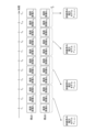
- Fig. 18 is a diagram showing an example of a trained restoration model stored in the model storage unit of the server device according to the second embodiment.
- the trained restoration model held by the model storage unit 606 is associated with time information.
- the trained restoration model F ⁇ 1_ ⁇ 3 is associated with the time information T 1 to T 3
- the trained restoration model F ⁇ 4_ ⁇ 6 is associated with the time information T 4 to T 6.
- the example of Fig. 18 shows that the trained restoration models F ⁇ 7_ ⁇ 9 and F ⁇ 10_ ⁇ 12 are associated with the time information T 7 to T 9 and T 10 to T 12 , respectively. That is, each model has time information that it corresponds to (supports).
- the association between the time information and the trained restoration model may be performed by directly associating the time information with the trained restoration model, or may be performed by indirectly associating the time information with the trained restoration model via other data.
- the server device 410 uses the trained restoration model stored in the model storage unit 606 to generate time-series view images according to the viewpoint information and time information included in the request received from the client terminal 420.
- the time information T1 , T2 , T3 , ... corresponds to the frame period of the captured image captured by the imaging device during the training process, as described above. Therefore, the time information T1 , T2 , T3 , ... corresponds to the frame period when the free viewpoint video is played back in the free viewpoint video playback system 400.
- the trained restoration models associated with each piece of time information are different from each other.
- the different trained restoration models referred to here are composed of NNs to which NeRF technology is applied, and are trained using different training data (captured images).
- the NN architecture may be the same or may have some different parts.
- each trained restoration model shown in FIG. 18 can generate a view image (free viewpoint image) from any viewpoint for the scene at each time point.
- the model storage unit 606 holds at least a group of trained restoration models for generating view images for a series of scenes for one target.
- the group of trained restoration models held by the model storage unit 606 is not limited to one, and the model storage unit 606 may hold another group of trained restoration models for generating view images for a series of scenes for another target.
- the group of trained restoration models held by the model storage unit 606 includes four trained restoration models corresponding to time information T 1 to T 11 due to space limitations.
- the number of trained restoration models included in the group of trained restoration models held by the model storage unit 606 is not limited to this.
- Fig. 19A is a first diagram showing a specific example of processing by the server device 410 according to the second embodiment.
- Fig. 19A shows a specific example of processing when the video designation acceptance unit 601 accepts designation of a free viewpoint video and the default video generating unit 602 is notified of identification information of the designated free viewpoint video from the video designation acceptance unit 601.
- the default video generation unit 602 reads, from the model storage unit 606, trained restoration models F ⁇ 1_ ⁇ 3 to F ⁇ 10_ ⁇ 12 for generating view images included in a specified free viewpoint video.
- the default video generator 602 also inputs default viewpoint information ( ⁇ 0 , ⁇ 0 ) and each piece of time information for each of the trained restoration models F ⁇ 1_ ⁇ 3 to F ⁇ 10_ ⁇ 12 that have been read out.
- the trained restoration models F ⁇ 1_ ⁇ 3 to F ⁇ 10_ ⁇ 12 view images X 1 to X 11 are generated at each piece of time information of the scene viewed from a viewpoint based on the default viewpoint information ( ⁇ 0 , ⁇ 0 ).
- default video generation unit 602 associates the generated view images X1 to X11 with time information T1 to T11 and notifies video transmission unit 605.
- video transmission unit 605 transmits view images X1 to X11 in a transmission format that allows video playback on client terminal 420.
- FIG. 19B is a second diagram showing a specific example of processing by the server device according to the second embodiment, and shows a specific example of processing by the requested video generating unit 604 when a request is notified from the request receiving unit 603.
- the requested video generation unit 604 identifies the trained restoration model F ⁇ 1_ ⁇ 3 corresponding to the time information included in the request (T 3 in the example of FIG. 19B) from among the trained restoration models F ⁇ 1_ ⁇ 3 to F ⁇ 10_ ⁇ 12 that have already been read out.
- the requested video generator 604 inputs the time information ( T3 in the example of FIG. 19B) and viewpoint information (( ⁇ x , ⁇ x ) in the example of FIG. 19B) included in the request to the identified trained restoration model F ⁇ 1_ ⁇ 3 .
- the trained restoration model F ⁇ 1_ ⁇ 3 generates a view image X3 at the time information T3 of the scene seen from the viewpoint based on the viewpoint information ( ⁇ x , ⁇ x ) included in the request.
- the request video generating unit 604 specifies a trained restoration model F ⁇ 4_ ⁇ 6 as the next trained restoration model.
- the request video generating unit 604 also sequentially inputs each piece of time information (T 4 , T 5 , T 6 in the example of FIG. 19B) and viewpoint information included in the request (( ⁇ x , ⁇ x ) in the example of FIG . 19B) to the specified trained restoration model F ⁇ 4_ ⁇ 6.
- the trained restoration model F ⁇ 4_ ⁇ 6 sequentially generates view images X 4 to X 6 at each piece of time information T 4 to T 6 of the scene viewed from a viewpoint based on the viewpoint information ( ⁇ x , ⁇ x ) included in the request.
- Fig. 19B shows a state in which time information T10 is transmitted from the client terminal 420 as the end condition.
- the requested video generating unit 604 specifies the trained restoration model F ⁇ 10_ ⁇ 12 corresponding to the time information T10 transmitted as the termination condition as the last trained restoration model.
- the requested video generating unit 604 also inputs the time information T10 and viewpoint information included in the request (( ⁇ x , ⁇ x ) in the example of FIG. 19B ) to the specified trained restoration model F ⁇ 10_ ⁇ 12 .
- the trained restoration model F ⁇ 10_ ⁇ 12 generates a view image X10 at the time information T10 of the scene viewed from a viewpoint based on the viewpoint information ( ⁇ x , ⁇ x ) included in the request.
- the requested video generating unit 604 From a trained reconstruction model that corresponds to the time information contained in the request, - Up to a trained restoration model that meets the given termination criteria, A trained restoration model of the time series of the second time interval is used to generate a time series of view images of the first time interval according to the viewpoint information.
- Requested video generation unit 604 associates the generated view images X3 to X10 with time information T3 to T10 and sequentially notifies video transmission unit 605. This allows video transmission unit 605 to transmit view images X3 to X10 in a transmission format that allows video playback on client terminal 420.
- the one or more memories included in the server device 410 include: A trained restoration model (second restoration model) for generating a time series of view images for a first time interval is held, the trained restoration model (second restoration model) being a time series of a second time interval longer than the first time interval.
- One or more trained restoration models (second restoration models) are held, and each of the one or more trained restoration models (second restoration models) is a trained restoration model trained to output information of an image at input time information.
- one or more processors included in the server device 410 according to the second embodiment include: - Generate a time series view image of a first time interval according to the viewpoint information included in the request using a trained restoration model (second restoration model) of a time series of a second time interval from a trained restoration model (second restoration model) corresponding to the time information included in the request to a trained restoration model (second restoration model) corresponding to a specified termination condition.
- a mechanism for playing back free viewpoint video that is different from that of the first embodiment can be constructed.
- the model storage unit 606 has a trained restoration model that generates view images in three consecutive pieces of time information as a trained restoration model that generates view images in a plurality of consecutive pieces of time information.
- the model storage unit 606 may have a trained restoration model that generates view images in time information of the entire time range as a trained restoration model that generates view images in a plurality of consecutive pieces of time information.
- the entire time range here refers to a finite time range captured by an imaging device, and in the third embodiment, it is described as, for example, 3 minutes. Note that, if the frame period is 30 fps, a 3-minute free viewpoint video will include 5,400 frame images.
- FIG. 20 is a third diagram for explaining the overview of the training process of the restoration model.
- the difference from the training process 1500 described with reference to FIG. 15 in the second embodiment is that in the case of the training process 2000 shown in FIG.
- viewpoint information e.g., viewpoint information ( ⁇ 1 , ⁇ 1 )
- the restored model 110 (F ⁇ ) is expressed as follows for the combination of the input three-dimensional points, viewpoint information, and time information: - Colors of the three-dimensional point at each time point (for example, colors respectively specified by ( R1_1 , G1_1 , B1_1 ) to ( R1_5400 , G1_5400 , B1_5400 )), - Opacity at each time point of the three-dimensional point (for example, opacity specified by ⁇ 1_1 , . . . ⁇ 1_5400 , respectively); That is, the restoration model 110 (F ⁇ ) calculates the color and opacity of a certain 3D point at a certain viewpoint and at a certain time.
- the same processing is performed for a plurality of viewpoints on the restored model 110 (F ⁇ ) in the training process 2000.
- the example of Fig. 20 shows how the same processing is performed for two viewpoints (viewpoint 1 and viewpoint 2).
- viewpoint information e.g., viewpoint information ( ⁇ 2 , ⁇ 2 )
- the restored model 110 (F ⁇ ) is calculated as follows for the combination of the input 3D points, viewpoint information, and time information: - Colors of the three-dimensional point at each time point (for example, colors respectively specified by (R 2_1 , G 2_1 , B 2_1 ) to (R 2_5400 , G 2_5400 , B 2_5400 )), - Opacity at each time point of the three-dimensional point (for example, opacity specified by ⁇ 2_5400 to ⁇ 2_5400 , respectively); The combinations are output in sequence.
- a volume rendering process 120 is performed on the combination of color and opacity of the 3D points sequentially output from the restoration model 110 (F ⁇ ) for each of the multiple 3D points on each line of sight.
- the volume rendering process 120 calculates the color of each pixel of an image seen from a certain viewpoint at a certain time by using a volume rendering method. Specifically, the volume rendering process 120 calculates the color of each pixel at a certain time by performing volume rendering using a predetermined product-sum operation based on the color and opacity output from the restoration model 110 (F ⁇ ) for each of multiple three-dimensional points on the line of sight connecting the pixel and the viewpoint. As a result, the volume rendering process 120 generates a view image of a certain viewpoint at a certain time.
- the example of FIG. 20 shows how the volume rendering process 120 generates view images (view image 1 to view image 5400 of viewpoint 1) at each time information of viewpoint 1 and view images (view image 1 to view image 5400 of viewpoint 2) at each time information of viewpoint 2.
- the loss calculation process 130 is performed on the view images (view image 1 to view image 5400 of viewpoint 1) at each time information generated from viewpoint 1.
- the loss calculation process 130 is performed on the view images (view image 1 to view image 5400 of viewpoint 2) at each time information generated from viewpoint 2.
- the view images at each time information of viewpoint 1 are compared with the captured images at each time information captured by the imaging device of viewpoint 1 (captured image A1 to captured image A5400 ) to calculate an error.
- the view images at each time information of viewpoint 2 are compared with the captured images at each time information captured by the imaging device of viewpoint 2 (captured image B1 to captured image B5400 ) to calculate an error.
- the error calculated in the loss calculation process 130 is backpropagated through the restoration model 110 (F ⁇ ) by the error backpropagation method in the update process of the restoration model 110 (F ⁇ ).
- a trained restoration model (F ⁇ ) is generated according to the training process 2000 shown in FIG. 20 .
- Fig. 21 is a third diagram for explaining an overview of an image generation process using a trained restoration model.
- the image generation process for generating a view image of a viewpoint ij at time information T inputs three-dimensional points (x n , yn , z n ) related to the viewpoint ij, viewpoint information ( ⁇ i , ⁇ j ), and time information T to a trained restoration model 210 (F ⁇ ), and calculates the color and opacity of each three-dimensional point at the time information T as its output. Then, the image generation process performs a volume rendering process 120 based on the calculated color and opacity of each three-dimensional point for each pixel of the view image to generate a view image of the viewpoint ij at the time information T.
- Fig. 22 is a third diagram showing an example of a trained restoration model applied to a server device. Note that, in Fig. 22, for the sake of simplicity, a case in which two viewpoints, viewpoint 1 and viewpoint 2, are used is shown, but as described above, in the training process, images captured by an imaging device at viewpoints other than viewpoint 1 and viewpoint 2 may be used.
- the server device 410 includes: A pre-trained restoration model that is pre-trained to restore a scene from a first time to a second time using a time series of captured images obtained by capturing a scene successively in time from multiple viewpoints; applies.
- the server device 410 includes: Images A 1 to A 5400 captured by an imaging device at viewpoint 1 at time information T 1 to time information T 5400 ; Images B 1 to B 5400 captured by an imaging device at viewpoint 2 at time information T 1 to time information T 5400 ; A trained restoration model F ⁇ 1_ ⁇ 5400 , which has been trained using
- the time information T1 , T2 , T3 , ... corresponds to the frame period (an example of a first time interval) of the captured images A1 , A2 , ... or the captured images B1 , B2 , ... captured by the imaging device during the training process.
- a trained restoration model an example of a third restoration model for generating time-series view images of the first time interval is applied to the server device 410.
- Fig. 23 is a diagram showing an example of a trained restoration model stored in the model storage unit of the server device according to the third embodiment.
- the trained restoration model held in the model storage unit 606 is associated with time information. Specifically, the trained restoration model F ⁇ 1_ ⁇ 5400 is associated with the time information T 1 to T 5400 .
- the server device 410 uses the trained restoration model stored in the model storage unit 606 to generate time-series view images according to the viewpoint information and time information included in the request received from the client terminal 420.
- the time information T1 , T2 , T3 , ... corresponds to the frame period of the captured image captured by the imaging device during the training process, as described above. Therefore, the time information T1 , T2 , T3 , ... corresponds to the frame period when the free viewpoint video is played back in the free viewpoint video playback system 400.
- the trained restoration model shown in Figure 23 can generate view images from any viewpoint (free viewpoint images) for the scene at each time point.
- the model storage unit 606 holds at least one trained restoration model for generating view images for a series of scenes for one target.
- the number of trained restoration models held by the model storage unit 606 is not limited to one, and the model storage unit 606 may hold another trained restoration model for generating view images for a series of scenes for another target.
- Fig. 24A is a first diagram showing a specific example of processing by the server device 410 according to the third embodiment.
- Fig. 24A shows a specific example of processing when the video designation acceptance unit 601 accepts designation of a free viewpoint video and the default video generating unit 602 is notified of identification information of the designated free viewpoint video from the video designation acceptance unit 601.
- the default video generation unit 602 reads out, from the model storage unit 606, a trained restoration model F ⁇ 1_ ⁇ 5400 for generating view images included in a specified free viewpoint video.
- the default video generator 602 also sequentially inputs the default viewpoint information ( ⁇ 0 , ⁇ 0 ) and each piece of time information to the read trained restoration model F ⁇ 1_ ⁇ 5400 .
- the trained restoration model F ⁇ 1_ ⁇ 5400 sequentially generates view images X 1 to X 5400 at each piece of time information of the scene viewed from the viewpoint based on the default viewpoint information ( ⁇ 0 , ⁇ 0 ).
- default video generation unit 602 associates the generated view images X 1 to X 5400 with time information T 1 to T 5400 and notifies video transmission unit 605.
- video transmission unit 605 transmits view images X 1 to X 5400 in a transmission format that allows video playback on client terminal 420.
- FIG. 24B is a second diagram showing a specific example of processing by the server device according to the third embodiment, and shows a specific example of processing by the requested video generating unit 604 when a request is notified from the request receiving unit 603.
- the requested video generator 604 identifies the trained restoration model F ⁇ 1_ ⁇ 5400 that has already been read out.
- the requested video generator 604 inputs the time information ( T3 in the example of FIG. 24B) and viewpoint information (( ⁇ x , ⁇ x ) in the example of FIG. 24B) included in the request to the identified trained restoration model F ⁇ 1_ ⁇ 5400 .
- the trained restoration model F ⁇ 1_ ⁇ 5400 generates a view image X3 at time information T3 of the scene viewed from a viewpoint based on the viewpoint information ( ⁇ x , ⁇ x ) included in the request.
- the requested video generator 604 inputs the next time information T4 and the viewpoint information included in the request (( ⁇ x , ⁇ x ) in the example of FIG. 24B ) to the identified trained restoration model F ⁇ 1_ ⁇ 5400 .
- the trained restoration model F ⁇ 1_ ⁇ 5400 generates a view image X4 at the time information T4 of the scene seen from the viewpoint based on the viewpoint information ( ⁇ x , ⁇ x ) included in the request.
- Fig. 24B shows a state in which time information T10 is transmitted from the client terminal 420 as the end condition.
- the requested video generating unit 604 When the time information T 10 is transmitted from the client terminal 420 as a termination condition, the requested video generating unit 604 performs the following for the identified trained restored model F ⁇ 1_ ⁇ 5400 : Time information T10 as a termination condition, The viewpoint information included in the request (in the example of FIG. 24B, ( ⁇ x , ⁇ x )), As a result, the trained restoration model F ⁇ 1_ ⁇ 5400 generates a view image X 10 at time information T 10 of the scene viewed from a viewpoint based on the viewpoint information ( ⁇ x , ⁇ x ) included in the request.
- the requested video generator 604 uses the trained restoration model to generate a time series of view images with a frame period according to the viewpoint information from the time information included in the request to a specified end condition.
- Requested video generation unit 604 associates the generated view images X3 to X10 with time information T3 to T10 and sequentially notifies video transmission unit 605. This allows video transmission unit 605 to transmit view images X3 to X10 in a transmission format that allows video playback on client terminal 420.
- the one or more memories included in the server device 410 according to the third embodiment include:
- the image processing apparatus has a trained restoration model (third restoration model) for generating a time series of view images for a first time interval.
- the trained restoration model (third restoration model) is a single trained restoration model that is trained to receive time information and output image information according to the input time information.
- one or more processors included in the server device 410 according to the third embodiment include: Using the trained restoration model (third restoration model), generate view images from the time information included in the request to a specified termination condition, which are a time series of view images for a first time interval according to the viewpoint information included in the request.
- a mechanism for playing back free viewpoint video that is different from the mechanisms of the first and second embodiments can be constructed.
- the model storage unit 606 has been described as holding one trained restoration model for each piece of time information, and one trained restoration model generates a view image at one piece of time information.
- the trained restoration model held by the model storage unit 606 for each piece of time information is not limited to this, and may hold, for example, a trained differential restoration model that generates a difference image with respect to a view image generated by a trained restoration model of the previous piece of time information.
- the fourth embodiment will be described, focusing on the differences from the first embodiment.
- FIG. 25 is a fourth diagram for explaining the overview of the training process of the restoration model.
- the difference from the training process 100 described with reference to FIG. 1 in the first embodiment is that in the case of the training process 2500 shown in FIG. 25, A key recovery model 110 (F ⁇ ); A differential restoration model 2501 ( ⁇ F ⁇ 1 ), A differential restoration model 2502 ( ⁇ F ⁇ 2 ), The point is that
- the key recovery model 110 (F ⁇ ) has a 3D point in the 3D scene 140 (e.g., a point identified by ( x1 , y1 , z1 )); viewpoint information (e.g., viewpoint information ( ⁇ 1 , ⁇ 1 )) that specifies a direction vector representing a line of sight (e.g., Ray 1) from viewpoint 1 to the 3D point;
- viewpoint information e.g., viewpoint information ( ⁇ 1 , ⁇ 1 )
- a direction vector representing a line of sight e.g., Ray 1
- the key recovery model 110 (F ⁇ ) is able to calculate the following for the combination of the input three-dimensional points and viewpoint information:
- the same process is performed for a plurality of viewpoints for the key recovery model 110 (F ⁇ ).
- the example of Fig. 25 shows how the same process is performed for two viewpoints (viewpoint 1, view point 2).
- the key recovery model 110 (F ⁇ ) further includes a 3D point in the 3D scene 140 (e.g., a point identified by ( x2 , y2 , z2 )); viewpoint information (e.g., viewpoint information ( ⁇ 2 , ⁇ 2 )) that specifies a direction vector representing a line of sight (e.g., Ray 2) from viewpoint 2 to the 3D point;
- viewpoint information e.g., viewpoint information ( ⁇ 2 , ⁇ 2 )
- a direction vector representing a line of sight e.g., Ray 2
- the key recovery model 110 (F ⁇ ) is able to calculate the following for the combination of the input three-dimensional points and viewpoint information:
- the differential restoration model 2501 ( ⁇ F ⁇ 1 ) includes a 3D point in the 3D scene 140 (e.g., a point identified by ( x1 , y1 , z1 )); viewpoint information (e.g., viewpoint information ( ⁇ 1 , ⁇ 1 )) that specifies a direction vector representing a line of sight (e.g., Ray 1) from viewpoint 1 to the 3D point;
- viewpoint information e.g., viewpoint information ( ⁇ 1 , ⁇ 1 )
- the differential restoration model 2501 ( ⁇ F ⁇ 1 ) is a difference between the color and opacity of a 3D point output by the key restoration model 110 (F ⁇ ) and that of a 3D point generated one frame period earlier, which is the difference between the color and opacity of the 3D point output by the key restoration model 110 (F ⁇ ) and that of a 3D point generated one frame period earlier.
- Fig. 25 shows a state in which the same process is performed for two viewpoints (viewpoint 1, viewpoint 2).
- the differential restoration model 2501 ( ⁇ F ⁇ 1 ) further includes a 3D point in the 3D scene 140 (e.g., a point identified by ( x2 , y2 , z2 )); viewpoint information (e.g., viewpoint information ( ⁇ 2 , ⁇ 2 )) that specifies a direction vector representing a line of sight (e.g., Ray 2) from viewpoint 2 to the 3D point;
- viewpoint information e.g., viewpoint information ( ⁇ 2 , ⁇ 2 )
- the differential restoration model 2501 ( ⁇ F ⁇ 1 ) is a difference between the color and opacity of a 3D point output by the key restoration model 110 (F ⁇ ) and that of a 3D point generated one frame period earlier, which is the difference between the color and opacity of the 3D point output by the key restoration model 110 (F ⁇ ) and that of a 3D point generated one frame period earlier.
- a differential color for example, a differential color specified by ( ⁇ R 22 , ⁇ G 22 , ⁇ B 22 )
- the differential restoration model 2502 ( ⁇ F ⁇ 2 ) includes a 3D point in the 3D scene 140 (e.g., a point identified by ( x1 , y1 , z1 )); viewpoint information (e.g., viewpoint information ( ⁇ 1 , ⁇ 1 )) that specifies a direction vector representing a line of sight (e.g., Ray 1) from viewpoint 1 to the 3D point;
- viewpoint information e.g., viewpoint information ( ⁇ 1 , ⁇ 1 )
- the differential restoration model 2502 ( ⁇ F ⁇ 2 ) is a difference between the color and opacity of a 3D point generated one frame period earlier and the color and opacity of a 3D point generated two frame periods later than the color and opacity of the 3D point output by the key restoration model 110 (F ⁇ )
- Fig. 25 shows a state in which the same process is performed for two viewpoints (viewpoint 1, viewpoint 2).
- the differential restoration model 2502 ( ⁇ F ⁇ 2 ) further includes a 3D point in the 3D scene 140 (e.g., a point identified by ( x2 , y2 , z2 )); viewpoint information (e.g., viewpoint information ( ⁇ 2 , ⁇ 2 )) that specifies a direction vector representing a line of sight (e.g., Ray 2) from viewpoint 2 to the 3D point;
- viewpoint information e.g., viewpoint information ( ⁇ 2 , ⁇ 2 )
- the differential restoration model 2502 ( ⁇ F ⁇ 2 ) is a difference between the color and opacity of a 3D point generated one frame period earlier and the color and opacity of a 3D point generated two frame periods later than the color and opacity of the 3D point output by the key restoration model 110 (F ⁇ )
- a differential color for example, a differential color specified by ( ⁇ R 23 , ⁇ G 23 , ⁇ B 23 )) of the three-dimensional point at time information
- a volume rendering process 120 is performed on the combination of color and opacity of the 3D points output from the key recovery model 110 (F ⁇ ) for each of the multiple 3D points on each line of sight.
- the volume rendering process 120 calculates the color of each pixel of an image seen from a certain viewpoint by using a volume rendering method. Specifically, the volume rendering process 120 calculates the color of each pixel by performing volume rendering using a predetermined product-sum operation based on the color and opacity output from the key restoration model 110 (F ⁇ ) for each of multiple three-dimensional points on the line of sight connecting the pixel and the viewpoint. As a result, the volume rendering process 120 generates a view image of a certain viewpoint.
- FIG. 25 shows how a view image 1 of viewpoint 1 and a view image 1 of viewpoint 2 are generated by the volume rendering process 120.
- a volume rendering process 120 is performed on the combination of differential color and differential opacity of the 3D points output from differential restoration model 2501 ( ⁇ F ⁇ 1 ) and differential restoration model 2502 ( ⁇ F ⁇ 2 ) for each of the multiple 3D points on each line of sight.
- the volume rendering process 120 uses a volume rendering method to calculate the differential color of each pixel indicating the difference between an image seen from a certain viewpoint and an image seen from a certain viewpoint at the previous time.
- the differential color of each pixel indicating the difference is calculated by performing volume rendering using a predetermined product-sum operation based on the differential color and differential opacity output from the differential restoration model 2501 ( ⁇ F ⁇ 1 ) and the differential restoration model 2502 ( ⁇ F ⁇ 2 ) for each of multiple three-dimensional points on the line of sight connecting the pixel and the viewpoint.
- the volume rendering process 120 generates a differential view image from a certain viewpoint at the previous time.
- the example of FIG. 25 is calculated by the volume rendering process 120.
- Differential view images at each time point of viewpoint 1 Differential view image 1 and differential view image 2 at viewpoint 1
- Differential view images at each time point of viewpoint 2 Differential view image 1 and differential view image 2 at viewpoint 2
- It shows how it was generated.
- a loss calculation process 130 is performed on each of the generated view images of each viewpoint (view image 1 of viewpoint 1 and view image 1 of viewpoint 2). Specifically, the view image 1 of viewpoint 1 is compared with a captured image A1 captured by an imaging device of viewpoint 1 to calculate an error. The view image 1 of viewpoint 2 is compared with a captured image B1 captured by an imaging device of viewpoint 2 to calculate an error.
- the error calculated in the loss calculation process 130 is backpropagated through the key recovery model 110 (F ⁇ ) by the error backpropagation method in the update process of the key recovery model 110 (F ⁇ ).
- a trained key recovery model F ⁇ is generated according to the training process 2500 shown in FIG. 25 .
- the loss calculation process 130 is performed on each of the generated differential view images of each viewpoint (differential view image 1 of viewpoint 1 and differential view image 1 of viewpoint 2). Specifically, the differential view image 1 of viewpoint 1 is compared with the differential image (A 1 -A 2 ) generated in the differential image generation process 2510 to calculate an error. Also, the differential view image 1 of viewpoint 2 is compared with the differential image (B 1 -B 2 ) generated in the differential image generation process 2510 to calculate an error.
- the error calculated in the loss calculation process 130 is backpropagated through the differential restoration model 2501 ( ⁇ F ⁇ 1 ) by the error backpropagation method in the update process of the differential restoration model 2501 ( ⁇ F ⁇ 1 ).
- a trained differential restoration model ⁇ F ⁇ 1 is generated according to the training process 2500 shown in FIG. 25 .
- the loss calculation process 130 is performed on each of the generated differential view images of each viewpoint (differential view image 2 of viewpoint 1 and differential view image 2 of viewpoint 2). Specifically, the differential view image 2 of viewpoint 1 is compared with the differential image (A 2 -A 3 ) generated in the differential image generation process 2510 to calculate an error. Also, the differential view image 2 of viewpoint 2 is compared with the differential image (B 2 -B 3 ) generated in the differential image generation process 2510 to calculate an error.
- the error calculated in the loss calculation process 130 is backpropagated through the differential restoration model 2502 ( ⁇ F ⁇ 2 ) by the error backpropagation method in the update process of the differential restoration model 2502 ( ⁇ F ⁇ 2 ).
- a trained differential restoration model ⁇ F ⁇ 2 is generated according to the training process 2500 shown in FIG. 25 .
- Fig. 26 is a fourth diagram for explaining an overview of an image generation process using a trained restoration model.
- the image generation process for generating a view image of viewpoint ij at time information T inputs 3D points ( xn , yn , zn ) related to viewpoint ij and viewpoint information ( ⁇ i , ⁇ j ) into a trained key recovery model 210 ( F ⁇ ), and calculates, as its output, the color and opacity of each 3D point at time information T. Then, the image generation process generates a view image of viewpoint ij at time information T by performing volume rendering process 120 based on the calculated color and opacity of each 3D point for each pixel of the view image.
- the image generation process for generating a view image of a viewpoint ij at time information one step after the time information T inputs a 3D point ( xn , yn , zn ) related to the viewpoint ij and viewpoint information ( ⁇ i , ⁇ j ) to a trained differential restoration model 2601 ( ⁇ F ⁇ 1 ), and calculates, as its output, a differential color and differential opacity of each 3D point with respect to the time information T at the time information one step after the time information T.
- the image generation process performs a volume rendering process 120 based on the calculated differential color and differential opacity of each 3D point for each pixel of the view image, thereby generating a differential view image 1 of the viewpoint ij with respect to the time information T at the time information one step after the time information T. Also, the image generation process generates a view image 2 of the viewpoint ij by performing an addition process 2611 for adding the differential view image 1 of the viewpoint ij to the view image 1 of the viewpoint ij at the time information T.
- the image generation process for generating a view image of viewpoint ij at time information two units later than time information T inputs 3D points ( xn , yn , zn ) related to viewpoint ij and viewpoint information ( ⁇ i , ⁇ j ) to a trained differential restoration model 2602 ( ⁇ F ⁇ 2 ), and calculates, as its output, differential color and differential opacity of each 3D point in time information two units later than time information T and time information one unit later than time information T.
- the image generation process performs volume rendering process 120 based on the calculated differential color and differential opacity of each 3D point for each pixel of the view image, thereby generating a differential view image 2 of viewpoint ij at time information two units later than time information T and time information one unit later than time information T. Furthermore, the image generation process performs an addition process 2612 of adding the differential view image 2 of the viewpoint ij to the view image 2 of the viewpoint ij one image later than the time information T, thereby generating a view image 3 of the viewpoint ij.
- Fig. 27 is a fourth diagram showing an example of a trained restoration model applied to a server device. Note that, in Fig. 27, for the sake of simplicity, a case in which two viewpoints, viewpoint 1 and viewpoint 2, are used is shown, but as described above, in the training process, images captured by an imaging device at viewpoints other than viewpoint 1 and viewpoint 2 may be used.
- a pre-trained restoration model is applied to the server device 410, which is pre-trained to restore a scene from a first time to a second time using a time series of captured images obtained by capturing the scene successively over time from multiple viewpoints.
- the server device 410 includes: A captured image A1 captured by an imaging device at a viewpoint 1 at time information T1 ; A captured image B1 captured by an imaging device at a viewpoint 2 at time information T1 ; A trained key recovery model F ⁇ 1 that has been trained using
- the server device 410 includes: A difference image (A 1 -A 2 ) between a captured image A 1 captured by an imaging device at a viewpoint 1 at time information T 1 and a captured image A 2 captured by an imaging device at a viewpoint 1 at time information T 2 , A difference image (B 1 -B 2 ) between a photographed image B 1 photographed by an imaging device at a viewpoint 2 at time information T 1 and a photographed image B 2 photographed by an imaging device at a viewpoint 2 at time information T 2 , A trained differential restoration model ⁇ F ⁇ 1 that has been trained using is applied.
- the server device 410 includes: A difference image (A 2 -A 3 ) between a captured image A 2 captured by an imaging device at the viewpoint 1 at time information T 2 and a captured image A 3 captured by an imaging device at the viewpoint 1 at time information T 3 , A difference image (B 2 -B 3 ) between a photographed image B 2 photographed by an imaging device at a viewpoint 2 at time information T 2 and a photographed image B 3 photographed by an imaging device at a viewpoint 2 at time information T 3 , A trained differential restoration model ⁇ F ⁇ 2 that has been trained using
- the server device 410 has A captured image A4 captured by an imaging device at a viewpoint 1 at time information T4 ; A captured image B4 captured by an imaging device at a viewpoint 2 at time information T4 ; and A trained key recovery model F ⁇ 4 , which has been trained using
- the server device 410 includes: A difference image (A 4 -A 5 ) between a captured image A 4 captured by an imaging device at the viewpoint 1 at time information T 4 and a captured image A 5 captured by an imaging device at the viewpoint 1 at time information T 5 , A difference image (B 4 -B 5 ) between a photographed image B 4 photographed by an imaging device at the viewpoint 2 at time information T 4 and a photographed image B 5 photographed by an imaging device at the viewpoint 2 at time information T 5 , A trained differential restoration model ⁇ F ⁇ 1 that has been trained using is applied.
- the server device 410 includes: A difference image (A 5 -A 6 ) between a captured image A 5 captured by an imaging device at the viewpoint 1 at time information T 5 and a captured image A 6 captured by an imaging device at the viewpoint 1 at time information T 6 , A difference image (B 5 -B 6 ) between a photographed image B 5 photographed by an imaging device at the viewpoint 2 at time information T 5 and a photographed image B 6 photographed by an imaging device at the viewpoint 2 at time information T 6 , A trained differential restoration model ⁇ F ⁇ 2 that has been trained using
- each trained key restoration model and trained differential restoration model are associated with each piece of time information and managed as a time-series trained restoration model.
- the time information T1 , T4 , T7 , ... corresponds to a third time interval that is longer than the frame period (an example of a first time interval) of the captured images A1 , A2 , ... or the captured images B1 , B2 , ... captured by the imaging device during the training process.
- Fig. 28 is a diagram showing an example of the trained restoration model of the server device according to the fourth embodiment.
- the trained key recovery model and the trained differential recovery model held by the model storage unit 606 are associated with time information.
- the trained key recovery model F ⁇ 1 is associated with the time information T 1
- the trained differential recovery models ⁇ F ⁇ 1 and ⁇ F ⁇ 2 are associated with the time information T 2 to T 3.
- the trained key recovery model F ⁇ 4 and the trained differential recovery models ⁇ F ⁇ 1 and ⁇ F ⁇ 2 are associated with the time information T 4 to T 6.
- the trained key recovery model F ⁇ 7 and the trained differential recovery models ⁇ F ⁇ 1 and ⁇ F ⁇ 2 are associated with the time information T 7 to T 9
- the trained key recovery model F ⁇ 10 and the trained differential recovery model ⁇ F ⁇ 1 are associated with the time information T 10 to T 11 .
- the correspondence between the time information and the trained key recovery model (or the trained differential recovery model) may be performed by directly matching the time information with the trained key recovery model (or the trained differential recovery model), or by indirectly matching the time information with the trained key recovery model (or the trained differential recovery model) via other data.
- the server device 410 uses the trained key recovery model and trained differential recovery model stored in the model storage unit 606 to generate time-series view images according to the viewpoint information and time information included in the request received from the client terminal 420.
- the time information T1 , T2 , T3 , ... corresponds to the frame period of the captured image captured by the imaging device during the training process, as described above. Therefore, the time information T1 , T2 , T3 , ... corresponds to the frame period when the free viewpoint video is played back in the free viewpoint video playback system 400.
- the trained key recovery models or trained differential recovery models associated with each piece of time information are different trained key recovery models or trained differential recovery models.
- the different trained key recovery models or trained differential recovery models referred to here are composed of NNs to which NeRF technology is applied, and are trained using different training data (captured images).
- the NN architecture may be the same or may have some different parts.
- the server device 410 generates a view image (free viewpoint image) from any viewpoint for the scene at each time information.
- the model storage unit 606 holds at least a group of trained key recovery models and trained differential recovery models for generating view images for a series of scenes for one target.
- the group of trained key recovery models and trained differential recovery models held by the model storage unit 606 is not limited to one, and the model storage unit 606 may hold another group of trained key recovery models and trained differential recovery models for generating view images for a series of scenes for another target.
- the group of trained key recovery models and trained differential recovery models held by the model storage unit 606 includes, for the sake of space, four trained key recovery models and seven trained differential recovery models with time information T 1 to T 11.
- the number of the group of trained key recovery models and the number of trained differential recovery models held by the model storage unit 606 are not limited to this.
- Fig. 29A is a first diagram showing a specific example of processing by the server device 410 according to the fourth embodiment.
- Fig. 29A shows a specific example of processing when the video designation acceptance unit 601 accepts designation of a free viewpoint video and the default video generating unit 602 is notified of identification information of the designated free viewpoint video from the video designation acceptance unit 601.
- the default video generation unit 602 uses the following as a trained restoration model for generating view images included in the specified free viewpoint video: Trained key recovery models F ⁇ 1 , F ⁇ 4 , F ⁇ 7 , F ⁇ 10 , and Trained differential restoration models ⁇ F ⁇ 1 , ⁇ F ⁇ 2 corresponding to time information T 2 , T 3 , T 5 , T 6 , T 8 , T 9 , and T 11, respectively is read from the model storage unit 606.
- the default video generating unit 602 retrieved trained key recovery models F ⁇ 1 , F ⁇ 4 , F ⁇ 7 , F ⁇ 10 , and Trained differential restoration models ⁇ F ⁇ 1 , ⁇ F ⁇ 2 corresponding to time information T 2 , T 3 , T 5 , T 6 , T 8 , T 9 , and T 11, respectively For each, the default viewpoint information ( ⁇ 0 , ⁇ 0 ) is input.
- the trained key recovery models F ⁇ 1 , F ⁇ 4 , F ⁇ 7 , and F ⁇ 10 generate view images X 1 , X 4 , X 7 , and X 10 at each time information of the scene seen from a viewpoint based on the default viewpoint information ( ⁇ 0 , ⁇ 0 ).
- trained differential restoration models ⁇ F ⁇ 1 and ⁇ F ⁇ 2 corresponding to time information T 2 , T 3 , T 5 , T 6 , T 8 , T 9 , and T 11, respectively, generate differential images ⁇ X 1 , ⁇ X 2 , ⁇ X 4 , ⁇ X 5 , ⁇ X 7 , ⁇ X 8 , and ⁇ X 10 .
- a view image X 2 at time information T 2 of the scene viewed from a viewpoint based on the default viewpoint information ( ⁇ 0 , ⁇ 0 ) is generated.
- a view image X 3 at time information T 3 of the scene viewed from a viewpoint based on the default viewpoint information ( ⁇ 0 , ⁇ 0 ) is generated.
- a view image X 5 at time information T 5 of the scene viewed from a viewpoint based on the default viewpoint information ( ⁇ 0 , ⁇ 0 ) is generated.
- a view image X 6 at time information T 6 of the scene viewed from a viewpoint based on the default viewpoint information ( ⁇ 0 , ⁇ 0 ) is generated.
- a view image X 8 at time information T 8 of the scene viewed from a viewpoint based on the default viewpoint information ( ⁇ 0 , ⁇ 0 ) is generated.
- a view image X 9 at time information T 9 of the scene viewed from a viewpoint based on the default viewpoint information ( ⁇ 0 , ⁇ 0 ) is generated.
- a view image X 11 at time information T 11 of the scene viewed from a viewpoint based on the default viewpoint information ( ⁇ 0 , ⁇ 0 ) is generated.
- default video generation unit 602 associates the generated view images X1 to X11 with time information T1 to T11 and notifies video transmission unit 605.
- video transmission unit 605 transmits view images X1 to X11 in a transmission format that allows video playback on client terminal 420.
- the default video generating unit 602 generates view images X2 , X3, X5 , X6 , X8 , X9 , and X11 using difference images ⁇ X1 , ⁇ X2 , ⁇ X4 , ⁇ X5 , ⁇ X7 , ⁇ X8 , and ⁇ X10 . Also, in the above description, it is assumed that the default video generating unit 602 notifies the video transmitting unit 605 of the generated view images X2 , X3 , X5 , X6 , X8 , X9 , and X11 .
- the content of the processing by the default video generating unit 602 is not limited to this.
- the default video generating unit 602 may View images X 1 , X 4 , X 7 , and X 10 generated by a trained key recovery model; Difference images ⁇ X 1 , ⁇ X 2 , ⁇ X 4 , ⁇ X 5 , ⁇ X 7 , ⁇ X 8 , ⁇ X 10 generated by the trained differential restoration model, The video transmission unit 605 may be notified of this.
- client terminal 420 receives view images X1 , X4 , X7 , and X10 from server device 410.
- Client terminal 420 also receives difference images ⁇ X1 , ⁇ X2 , ⁇ X4, ⁇ X5 , ⁇ X7, ⁇ X8 , and ⁇ X10 from server device 410.
- client terminal 420 generates view images X2 , X3 , X5 , X6 , X8 , X9 , and X11 using the received view images X1 , X4 , X7 , and X10 and the received difference images ⁇ X1 , ⁇ X2 , ⁇ X4 , ⁇ X5 , ⁇ X7 , ⁇ X8 , and ⁇ X10 .
- part of the processing performed by the default video generating unit 602 may be executed by the client terminal 420.
- FIG. 29B is a second diagram showing a specific example of processing by the server device according to the fourth embodiment, and shows a specific example of processing by the requested video generating unit 604 when a request is notified from the request receiving unit 603.
- the request moving image generating unit 604 identifies a trained differential restoration model ⁇ F ⁇ 2 corresponding to the time information included in the request (T 3 in the example of FIG. 29B) from among the trained restoration models that have already been read out. In addition, the request moving image generating unit 604 identifies a trained key restoration model F ⁇ 1 and a trained differential restoration model ⁇ F ⁇ 1 that are necessary to generate a view image X 3 based on the trained differential restoration model ⁇ F ⁇ 2 .
- the requested video generator 604 inputs the viewpoint information (( ⁇ x , ⁇ x ) in the example of FIG. 29B) included in the request to the identified trained key recovery model F ⁇ 1 and trained differential recovery models ⁇ F ⁇ 1 and ⁇ F ⁇ 2 .
- the trained key recovery model F ⁇ 1 generates a view image X1 at the time information T1 of the scene viewed from the viewpoint based on the viewpoint information ( ⁇ x , ⁇ x ) included in the request.
- the trained differential recovery models ⁇ F ⁇ 1 and ⁇ F ⁇ 2 generate differential images ⁇ X1 and ⁇ X2 at the time information T2 and T3 of the scene viewed from the viewpoint based on the viewpoint information ( ⁇ x , ⁇ x ) included in the request.
- the requested video generation unit 604 uses the generated view image X1 and difference images ⁇ X1 and ⁇ X2 to generate a view image X3 at time information T3 of the scene viewed from a viewpoint based on the viewpoint information ( ⁇ x , ⁇ x ) included in the request.
- the requested motion picture generating unit 604 specifies a trained key recovery model F ⁇ 4 corresponding to the next time information (next time) as the next trained recovery model.
- the requested motion picture generating unit 604 also inputs the viewpoint information ( ⁇ x , ⁇ x ) included in the request to the specified trained key recovery model F ⁇ 4 .
- the trained key recovery model F ⁇ 4 generates a view image X4 at the time information T4 of the scene viewed from a viewpoint based on the viewpoint information ( ⁇ x , ⁇ x ) included in the request.
- the request video generating unit 604 specifies a trained differential restoration model ⁇ F ⁇ 1 corresponding to the next time information (next time) as the next trained restoration model.
- the request video generating unit 604 inputs viewpoint information ( ⁇ x , ⁇ x ) included in the request to the specified trained differential restoration model ⁇ F ⁇ 1 .
- the trained differential restoration model ⁇ F ⁇ 1 generates a difference image ⁇ X 4 at the time information T 5 of the scene viewed from the viewpoint based on the viewpoint information ( ⁇ x , ⁇ x ) included in the request.
- the request video generating unit 604 uses the generated view image X 4 and difference image ⁇ X 4 to generate a view image X 5 at the time information T 5 of the scene viewed from the viewpoint based on the viewpoint information ( ⁇ x , ⁇ x ) included in the request.
- the request video generating unit 604 specifies a trained differential restoration model ⁇ F ⁇ 2 corresponding to the next time information (next time) as the next trained restoration model.
- the request video generating unit 604 inputs viewpoint information ( ⁇ x , ⁇ x ) included in the request to the specified trained differential restoration model ⁇ F ⁇ 2 .
- the trained differential restoration model ⁇ F ⁇ 2 generates a difference image ⁇ X 5 at the time information T 6 of the scene viewed from the viewpoint based on the viewpoint information ( ⁇ x , ⁇ x ) included in the request.
- the request video generating unit 604 uses the generated view image X 5 and difference image ⁇ X 5 to generate a view image X 6 at the time information T 6 of the scene viewed from the viewpoint based on the viewpoint information ( ⁇ x , ⁇ x ) included in the request.
- Fig. 29B shows a state in which time information T10 is transmitted from the client terminal 420 as the end condition.
- the requested motion picture generating unit 604 specifies the trained key recovery model F ⁇ 10 corresponding to the time information T10 transmitted as the termination condition as the last trained key recovery model.
- the requested motion picture generating unit 604 also inputs the viewpoint information included in the request (( ⁇ x , ⁇ x ) in the example of FIG. 29B ) to the specified trained recovery model F ⁇ 10 .
- the trained key recovery model F ⁇ 10 generates a view image X10 at the time information T10 of the scene viewed from a viewpoint based on the viewpoint information ( ⁇ x , ⁇ x ) included in the request.
- the requested video generating unit 604 Generate a time series view image of a third time interval according to the viewpoint information using a trained key recovery model of a third time interval from a trained key recovery model corresponding to the time information included in the request to a trained key recovery model corresponding to a specified termination condition.
- a time-series trained differential restoration model for a first time interval from a trained differential restoration model corresponding to the time information included in the request to a trained differential restoration model corresponding to a predetermined termination condition
- a time-series differential image for a first time interval is generated according to viewpoint information, the differential image corresponding to time information excluding time information for which a view image is generated using the time-series trained key restoration model.
- a time series of view images for the first time interval is generated, excluding view images generated using the trained key recovery model.
- Requested video generation unit 604 associates the generated view images X3 to X10 with time information T3 to T10 and sequentially notifies video transmission unit 605. As a result, video transmission unit 605 transmits view images X3 to X10 in a transmission format that allows video playback on client terminal 420.
- the one or more memories included in the server device 410 include: - Holding a trained key recovery model (fourth recovery model) of a time series of a third time interval for generating a time series of view images of a third time interval longer than the first time interval. Holding a trained differential restoration model (fourth differential restoration model) used when generating view images, excluding view images generated using a trained key restoration model (fourth restoration model), from among view images of a time series of a first time interval.
- the trained differential restoration model (fourth differential restoration model) is a trained differential restoration model of a time series of a first time interval that generates a difference image representing a difference from a view image generated just the first time interval before.
- one or more processors included in the server device 410 according to the fourth embodiment include: - Generate a time series view image of the third time interval according to the viewpoint information using a trained key recovery model (fourth recovery model) of a third time interval from a trained key recovery model (fourth recovery model) corresponding to the time information included in the request to a trained key recovery model (fourth recovery model) corresponding to a specified termination condition.
- a time-series trained differential restoration model (fourth differential restoration model) of a first time interval is generated according to viewpoint information.
- the difference image is a time-series difference image corresponding to time information excluding time information at which a view image is generated using the time-series trained key restoration model (fourth restoration model).
- a mechanism for playing back free viewpoint video that is different from the mechanisms of the first to third embodiments can be constructed.
- FIG. 30 is a fifth diagram for explaining the overview of the training process of the restoration model. In the case of the training process 3000 shown in FIG.
- the space 1 restoration model 110_1 (F ⁇ ) includes A 3D point in the upper half space (space 1) in the 3D scene 140 (e.g., a point identified by ( x1_1 , y1_1 , z1_1 )); viewpoint information (e.g., viewpoint information ( ⁇ 1 , ⁇ 1 )) that specifies a direction vector representing a line of sight (e.g., Ray 1) from viewpoint 1 to the 3D point;
- viewpoint information e.g., viewpoint information ( ⁇ 1 , ⁇ 1 )
- the space 1 restoration model 110_1 (F ⁇ ) is calculated as follows for the combination of the input three-dimensional points and viewpoint information:
- the color of the 3D point in the upper half space (space 1) in the 3D scene 140 for example, the color specified by (R 1_1 , G 1_1 , B 1_1 )); the o
- the same processing is performed for a plurality of viewpoints on the space 1 restoration model 110_1 (F ⁇ ) in the training process 3000.
- the example of Fig. 30 shows how the same processing is performed for two viewpoints (viewpoint 1, viewpoint 2).
- the space 1 restoration model 110_1 (F ⁇ ) further includes A 3D point in the upper half space (space 1) in the 3D scene 140 (e.g., a point identified by ( x2_1 , y2_1 , z2_1 )); viewpoint information (e.g., viewpoint information ( ⁇ 2 , ⁇ 2 )) that specifies a direction vector representing a line of sight (e.g., Ray 2) from viewpoint 2 to the 3D point;
- viewpoint information e.g., viewpoint information ( ⁇ 2 , ⁇ 2 )
- a direction vector representing a line of sight e.g., Ray 2
- the space 1 restoration model 110_2 (F ⁇ ) is calculated as follows for the combination of the input three-dimensional points and viewpoint information:
- the color of the 3D point in the upper half space (space 1) in the 3D scene 140 for example, the color specified by (R 2_1 , G 2_1 , B 2_1 )
- the space 2 restoration model 110_1 has the following: A 3D point in the lower half space (space 2) in the 3D scene 140 (e.g., a point identified by ( x1_2 , y1_2 , z1_2 )); and viewpoint information (e.g., viewpoint information ( ⁇ 1 , ⁇ 1 )) that specifies a direction vector that represents a line of sight (e.g., Ray 1) from viewpoint 1 with respect to the 3D point.
- viewpoint information e.g., viewpoint information ( ⁇ 1 , ⁇ 1 )
- the space 2 restoration model 110_1 (F ⁇ ) determines, for the combination of the input 3D point and viewpoint information, The color of the 3D point in the lower half space (space 2) in the 3D scene 140 (e.g., the color specified by (R 1_2 , G 1_2 , B 1_2 )), the opacity of the 3D point in the lower half space (Space 2) in the 3D scene 140 (e.g., the opacity specified by ⁇ 1_2 ); That is, the space 2 restoration model 110_1 (F ⁇ ) calculates the color and opacity of a certain three-dimensional point in the space 2 at a certain viewpoint.
- the color of the 3D point in the lower half space (space 2) in the 3D scene 140 e.g., the color specified by (R 1_2 , G 1_2 , B 1_2 )
- the opacity of the 3D point in the lower half space (Space 2) in the 3D scene 140 e.g., the
- the same processing is performed for a plurality of viewpoints on the space 2 restoration model 110_2 (F ⁇ ) in the training process 3000.
- the example of Fig. 30 shows how the same processing is performed for two viewpoints (viewpoint 1, viewpoint 2).
- the space 2 restoration model 110_2 (F ⁇ ) further includes A 3D point in the lower half space (space 2) in the 3D scene 140 (e.g., a point identified by ( x2_2 , y2_2 , z2_2 )); viewpoint information (e.g., viewpoint information ( ⁇ 2 , ⁇ 2 )) that specifies a direction vector representing a line of sight (e.g., Ray 2) from viewpoint 2 to the 3D point;
- viewpoint information e.g., viewpoint information ( ⁇ 2 , ⁇ 2 )
- the space 2 restoration model 110_1 (F ⁇ ) is calculated as follows for the combination of the input three-dimensional points and viewpoint information:
- the color of the 3D point in the lower half space (space 2) in the 3D scene 140 e.g., the color specified by (R 2_2 , G 2_2 , B 2_2 )
- the opacity of the 3D point in the lower half space (Space 2) in the 3D scene 140
- a volume rendering process 120 is performed on the combination of color and opacity of the 3D points output from the space 1 restoration model 110_1 (F ⁇ ) for each of the multiple 3D points on each line of sight.
- the volume rendering process 120 calculates the color of each pixel of an image seen from a certain viewpoint by using a volume rendering method. Specifically, the volume rendering process 120 calculates the color of each pixel in space 1 by performing volume rendering using a predetermined product-sum operation based on the color and opacity output from the space 1 restoration model 110_1 (F ⁇ ) for each of a plurality of three-dimensional points on the line of sight connecting the pixel and the viewpoint. As a result, the volume rendering process 120 generates a view image of space 1 from a certain viewpoint.
- FIG. 30 shows a state in which a view image (space 1) from viewpoint 1 and a view image (space 1) from viewpoint 2 are generated by the volume rendering process 120.
- the volume rendering process 120 calculates the color of each pixel in space 2 by performing volume rendering using a predetermined product-sum operation based on the color and opacity output from the space 2 restoration model 110_2 (F ⁇ ) for each of multiple three-dimensional points on the line of sight connecting the pixel and the viewpoint. As a result, the volume rendering process 120 generates a view image of space 2 from a certain viewpoint.
- the example of Fig. 30 shows how a view image (space 2) from viewpoint 1 and a view image (space 2) from viewpoint 2 are generated by the volume rendering process 120.
- a loss calculation process 130 is performed on the generated view image (space 1) of viewpoint 1 and the view image (space 1) of viewpoint 2.
- the view image (space 1) of viewpoint 1 is compared with the captured image A 1_1 captured by the imaging device of viewpoint 1 to calculate an error.
- the view image (space 1) of viewpoint 2 is compared with the captured image B 1_1 captured by the imaging device of viewpoint 2 to calculate an error.
- a loss calculation process 130 is performed on each of the generated view image (space 2) of viewpoint 1 and the view image (space 2) of viewpoint 2.
- the view image (space 2) of viewpoint 1 is compared with a captured image A 1_2 captured by an imaging device of viewpoint 1 to calculate an error.
- the view image (space 2) of viewpoint 2 is compared with a captured image B 1_2 captured by an imaging device of viewpoint 2 to calculate an error.
- the error calculated in the loss calculation process 130 is backpropagated through the space 1 restoration model 110_1 (F ⁇ ) and the space 2 restoration model 110_2 (F ⁇ ) by the error backpropagation method in the update process of the space 1 restoration model 110_1 (F ⁇ ) and the space 2 restoration model 110_2 (F ⁇ ).
- the model parameters of the space 1 restoration model 110_1 (F ⁇ ) and the model parameters of the space 2 restoration model 110_2 (F ⁇ ) are updated.
- the model parameters are updated by the training process of the space 1 restoration model 110_1 (F ⁇ ), and the trained space 1 restoration model (F ⁇ ) is generated according to the training process shown in FIG. 30.
- the model parameters are updated by the training process of the space 2 restoration model 110_2 (F ⁇ ), and the trained space 2 restoration model (F ⁇ ) is generated according to the training process shown in FIG. 30.
- Fig. 31 is a fifth diagram for explaining an overview of an image generation process using a trained restoration model.
- the image generation process for generating a view image of viewpoint ij in space 1 inputs 3D points ( xn , yn , zn ) and viewpoint information ( ⁇ i , ⁇ j ) related to viewpoint ij into a trained space 1 restoration model 3110_1 ( F ⁇ ), and calculates the color and opacity of each 3D point as its output. Then, the image generation process performs a volume rendering process 120 based on the calculated color and opacity of each 3D point for each pixel of the view image in space 1, thereby generating a view image of viewpoint ij in space 1.
- the image generation process for generating a view image of viewpoint ij in space 2 inputs 3D points ( xn , yn , zn ) and viewpoint information ( ⁇ i , ⁇ j ) related to viewpoint ij into a trained space 2 restoration model 3110_2 ( F ⁇ ), and calculates the color and opacity of each 3D point as its output. Then, the image generation process generates a view image of viewpoint ij in space 2 by performing volume rendering process 120 based on the calculated color and opacity of each 3D point for each pixel of the view image in space 2.
- Fig. 32 is a fifth diagram showing an example of a trained restoration model applied to the server device. Note that, in Fig. 32, for the sake of simplicity, a case in which two viewpoints, viewpoint 1 and viewpoint 2, are used is shown, but as described above, in the training process, images captured by an imaging device at viewpoints other than viewpoint 1 and viewpoint 2 may be used.
- a group of trained restoration models corresponding to each space is applied to the server device 410.
- the group of trained restoration models corresponding to each space is trained in advance to restore a scene from a first time to a second time using a time series of captured images obtained by capturing images of each space of the scene successively in time from multiple viewpoints.
- the server device 410 includes: A captured image A 1_1 of a space 1 captured by an imaging device at a viewpoint 1 at time information T 1 ; and A captured image B1_1 of a space 1 captured by an imaging device at a viewpoint 2 at time information T1 ; and A trained space 1 restoration model F ⁇ 1 , which has been trained using A captured image A1_2 of a space 2 captured by an imaging device at a viewpoint 1 at time information T1 ; and A captured image B1_2 of a space 2 captured by an imaging device at a viewpoint 2 at time information T1 ; and A trained spatial 2 reconstruction model F ⁇ 1 , which has been trained using
- the server device 410 has A captured image A2_1 of space 1 captured by an imaging device at viewpoint 1 at time information T2 ; and A captured image B2_1 of the space 1 captured by an imaging device at the viewpoint 2 at time information T2 ; and A trained space 1 reconstruction model F ⁇ 2 that has been trained using A captured image A2_2 of a space 2 captured by an imaging device at a viewpoint 1 at time information T2 ; and A captured image B2_2 of space 2 captured by an imaging device at viewpoint 2 at time information T2 ; and A trained spatial 2 reconstruction model F ⁇ 2 , which has been trained using
- each trained restoration model is managed as a time-series trained restoration model associated with time information and space information.
- time information T 1 , T 2 , T 3 , . . . are taken by an imaging device during the training process.
- a trained restoration model another example of a first restoration model of a time series of a first time interval corresponding to each space is applied to the server device 410 in order to generate a time series of view images of the first time interval of each space.
- Fig. 33 is a diagram showing an example of a trained restoration model of the server device according to the fifth embodiment.
- the trained restoration model held by the model storage unit 606 is associated with time information.
- the trained space 1 restoration model F ⁇ 1 and the trained space 2 restoration model F ⁇ 1 are associated with the time information T 1
- the trained space 1 restoration model F ⁇ 2 and the trained space 2 restoration model F ⁇ 2 are associated with the time information T 2.
- the example of FIG. 33 shows that the trained space 1 restoration model F ⁇ 3 and the trained space 2 restoration model F ⁇ 3 to the trained space 1 restoration model F ⁇ 11 and the trained space 2 restoration model F ⁇ 11 are associated with the time information T 3 to T 11 , respectively.
- the association between the time information and the trained space 1 restoration model and the trained space 2 restoration model may be performed by directly associating the time information with the trained space 1 restoration model and the trained space 2 restoration model, or may be performed by indirectly associating the time information with the trained space 1 restoration model and the trained space 2 restoration model via other data.
- the server device 410 uses the trained restoration model corresponding to each space held by the model storage unit 606 to generate time-series view images according to the viewpoint information, time information, and spatial information contained in the request received from the client terminal 420.
- the time information T1 , T2 , T3 , ... corresponds to the frame period of the captured image captured by the imaging device during the training process, as described above. Therefore, the time information T1 , T2 , T3 , ... corresponds to the frame period when the free viewpoint video is played back in the free viewpoint video playback system 400.
- the trained space 1 restoration model or the trained space 2 restoration model associated with each piece of time information is a trained space 1 restoration model or a trained space 2 restoration model that is different from each other.
- the trained space 1 restoration model or the trained space 2 restoration model that is different from each other here is composed of a NN to which NeRF technology is applied, and is trained using training data (captured images) that are different from each other.
- the NN architecture may be the same or may have some different parts.
- each trained space 1 restoration model or each trained space 2 restoration model shown in FIG. 33 can generate a view image (free viewpoint image) from any viewpoint for the corresponding space in the scene of each time information.
- the model storage unit 606 holds at least a set of trained space 1 restoration models and trained space 2 restoration models for each space, for generating view images for a series of scenes for one target.
- the set of trained space 1 restoration models and trained space 2 restoration models held by the model storage unit 606 is not limited to one, and the model storage unit 606 may hold another set of trained space 1 restoration models and trained space 2 restoration models for each space, for generating view images for a series of scenes for another target.
- the group of trained space 1 restoration models and trained space 2 restoration models held by the model storage unit 606 includes 22 trained space 1 restoration models and trained space 2 restoration models with time information T 1 to T 11 due to space limitations.
- the number of trained space 1 restoration models and trained space 2 restoration models held by the model storage unit 606 is not limited to this.
- Fig. 34A is a first diagram showing a specific example of processing by the server device 410 according to the fifth embodiment.
- Fig. 34A shows a specific example of processing when the video designation acceptance unit 601 accepts designation of a free viewpoint video and the default video generating unit 602 is notified of identification information of the designated free viewpoint video from the video designation acceptance unit 601.
- the default video generation unit 602 uses the following as a trained restoration model for generating view images included in the specified free viewpoint video: Trained space 1 reconstruction models F ⁇ 1 to F ⁇ 11 , and Trained space 2 reconstruction models F ⁇ 1 to F ⁇ 11 , is read from the model storage unit 606.
- the default video generating unit 602 inputs default viewpoint information ( ⁇ 0 , ⁇ 0 ) to each of the trained space 1 restoration models F ⁇ 1 to F ⁇ 11 and the trained space 2 restoration models F ⁇ 1 to F ⁇ 11 that have been read out.
- the trained space 1 restoration models F ⁇ 1 to F ⁇ 11 generate view images X 1_1 to X 11_1 at each time information of the space 1 of the scene seen from the viewpoint based on the default viewpoint information ( ⁇ 0 , ⁇ 0 ).
- the trained space 2 restoration models F ⁇ 1 to F ⁇ 11 generate view images X 1_2 to X 11_2 at each time information of the space 2 of the scene seen from the viewpoint based on the default viewpoint information ( ⁇ 0 , ⁇ 0 ).
- default video generating unit 602 associates the generated view image X1_1 , view image X1_2 to view image X11_1 , and view image X11_2 with time information T1 to T11 , and notifies video transmitting unit 605.
- video transmitting unit 605 transmits view image X1_1 , view image X1_2 to view image X11_1 , and view image X11_2 in a transmission format that allows video playback on client terminal 420.
- FIG. 34B is a second diagram showing a specific example of processing by the server device according to the fifth embodiment, and shows a specific example of processing by the requested video generating unit 604 when a request is notified from the request receiving unit 603.
- the request video generation unit 604 identifies a trained space 1 restoration model F ⁇ 3 corresponding to the request (T 3 , space 1 in the example of Figure 34B) from among the trained space 1 restoration models and trained space 2 restoration models that have already been read out.
- the requested video generator 604 inputs the viewpoint information included in the request (( ⁇ x , ⁇ x ) in the example of FIG. 34B ) to the identified trained space 1 restoration model F ⁇ 3 .
- the trained space 1 restoration model F ⁇ 3 generates a view image X 3_1 of the space 1 at the time information T 3 of the scene seen from the viewpoint based on the viewpoint information ( ⁇ x , ⁇ x ) included in the request.
- the request video generator 604 specifies the trained space 1 restoration model F ⁇ 4 corresponding to the next time information (next time) as the next trained restoration model.
- the request video generator 604 also inputs the viewpoint information included in the request (( ⁇ x , ⁇ x ) in the example of FIG. 34B ) to the specified trained space 1 restoration model F ⁇ 4 .
- the trained space 1 restoration model F ⁇ 4 generates a view image X 4_1 of the space 1 in the time information T 4 of the scene seen from the viewpoint based on the viewpoint information ( ⁇ x , ⁇ x ) included in the request.
- Fig. 34B shows a state in which time information T10 is transmitted from the client terminal 420 as the end condition.
- the requested video generation unit 604 specifies the trained space 1 restoration model F ⁇ 10 corresponding to the time information T10 transmitted as the termination condition as the last trained restoration model.
- the requested video generation unit 604 also inputs the viewpoint information included in the request (( ⁇ x , ⁇ x ) in the example of FIG. 34B ) to the specified trained space 1 restoration model F ⁇ 10.
- the trained space 1 restoration model F ⁇ 10 generates a view image X10 of the space 1 in the time information T10 of the scene seen from a viewpoint based on the viewpoint information ( ⁇ x , ⁇ x ) included in the request.
- the requested video generating unit 604 A trained reconstruction model of a time series for a first time interval from a trained reconstruction model corresponding to the time information included in the request to a trained reconstruction model corresponding to a predetermined termination condition, A trained reconstruction model of the time series corresponding to the spatial information contained in the request; to generate a time series of view images at a first time interval according to the viewpoint information.
- Requested video generation unit 604 associates the generated view images X3_1 to X10_1 of space 1 with time information T3 to T10 , and sequentially notifies video transmission unit 605. This allows video transmission unit 605 to transmit view images X3_1 to X10_1 in a transmission format that allows video playback on client terminal 420.
- Fig. 35 is a second sequence diagram showing the flow of free viewpoint video playback processing by the free viewpoint video playback system.
- step S3520_1 the client terminal 420 accepts a designation from the user 440 regarding the free viewpoint video to be displayed, and transmits identification information for uniquely identifying the designated free viewpoint video to the server device 410.
- step S3510_1 the server device 410 reads out a group of trained space 1 restoration models and trained space 2 restoration models for space 1 and space 2 for generating view images included in the specified free viewpoint video.
- the server device 410 also inputs default viewpoint information ( ⁇ 0 , ⁇ 0 ) into the read out trained space 1 restoration model and trained space 2 restoration model to generate view images X 1_1 to X 11_1 for space 1 and view images X 1_2 to X 11_2 for space 2.
- step S3510_2 the server device 410 sequentially transmits the generated view images of space 1 and space 2 to the client terminal 420.
- step S3520_2 the client terminal 420 plays a free viewpoint video in which the view images of space 1 and space 2 transmitted from the server device 410 are used as frame images.
- the client terminal 420 also receives an instruction to stop the free viewpoint video being played and transmits it to the server device 410.
- the server device 410 stops transmitting the view images of space 1 and space 2.
- step S3520_3 the client terminal 420 receives an instruction to move the indicator 1112' on the seek bar 1112.
- the client terminal 420 sequentially transmits time information for each position of the moving indicator 1112' to the server device 410.
- step S3510_3 each time the server device 410 receives time information for each position of the moving indicator 1112' from the client terminal 420, it inputs default viewpoint information into the trained space 1 restoration model and the trained space 2 restoration model for space 1 and space 2 corresponding to the time information for each position. As a result, the server device 410 generates view images for space 1 and space 2. The server device 410 also sequentially transmits the generated view images for space 1 and space 2 to the client terminal 420. As a result, the view images for space 1 and space 2 corresponding to the time information for each position of the moving indicator 1112' are displayed on the client terminal 420.
- step S3520_4 the client terminal 420 accepts the dragging of the video display area by the mouse pointer 1116.
- the client terminal 420 transmits viewpoint information for each position of the moving mouse pointer 1116 to the server device 410.
- step S3510_4 each time the server device 410 receives viewpoint information for each position of the moving mouse pointer 1116 from the client terminal 420, it inputs the viewpoint information for each position into the trained space 1 restoration model and the trained space 2 restoration model for space 1 and space 2 that correspond to the current time information. As a result, the server device 410 generates view images for space 1 and space 2. The server device 410 also sequentially transmits the generated view images for space 1 and space 2 to the client terminal 420. As a result, the view images for space 1 and space 2 that correspond to the viewpoint information for each position of the moving mouse pointer 1116 are displayed on the client terminal 420.
- step S3520_5 the client terminal 420 accepts input of spatial information (e.g., space 1) and transmits it to the server device 410.
- spatial information e.g., space 1
- step S3520_6 when the play button 1114 is pressed, the client terminal 420 sends a play instruction to the server device 410.
- step S3510_5 the server device 410 generates a view image of space 1 by inputting the current viewpoint information into a trained space 1 restoration model corresponding to the current time information and the input spatial information (space 1), and transmits it to the client terminal 420.
- the server device 410 generates a view image of space 1 by inputting the current viewpoint information into a trained space 1 restoration model corresponding to the next time information and the input spatial information (space 1), and transmits it to the client terminal 420. Thereafter, the server device 410 repeats the same process until an end condition is transmitted from the client terminal 420.
- step S3520_7 the client terminal 420 plays a free viewpoint video in which the view image of space 1 transmitted from the server device 410 is used as a frame image.
- the client terminal 420 also receives an instruction to stop the free viewpoint video being played and transmits it to the server device 410.
- the server device 410 stops generating and transmitting the view image of space 1.
- the server device 410 includes one or more memories and one or more processors. - For a specific space, a trained space 1 restoration model or a trained space 2 restoration model (first restoration model) for generating a time series of view images for a first time interval, and a trained space 1 restoration model or a trained space 2 restoration model (first restoration model) for a time series of the first time interval is held.
- one or more processors included in the server device 410 according to the fifth embodiment include: Generate a time series view image for a first time interval according to viewpoint information using a trained space 1 restoration model or trained space 2 restoration model (first restoration model) of a time series for a first time interval from a trained space 1 restoration model or trained space 2 restoration model (first restoration model) corresponding to the time information included in the request to a trained space 1 restoration model or trained space 2 restoration model (first restoration model) corresponding to a predetermined termination condition.
- the trained space 1 restoration model or trained space 2 restoration model (first restoration model) of the time series for the first time interval is a trained restoration model corresponding to the spatial information included in the request.
- a mechanism can be constructed for playing back free viewpoint video about a specific space.
- the user 440 inputs time information, viewpoint information, and (spatial information) to the client terminal 420, and the server device 410 generates a view image according to the input time information, viewpoint information, and (spatial information).
- the mechanism for playing back free viewpoint video on the client terminal 420 is not limited to this.
- the user 440 may input time information and (spatial information), and the server device 410 may transmit a trained restoration model corresponding to the input time information and (spatial information) to the client terminal 420.
- the client terminal 420 executes the received time-series trained restoration model based on the viewpoint information input by the user 440, thereby generating a view image corresponding to the viewpoint information and playing back the free viewpoint video.
- the sixth embodiment will be described, focusing on the differences from the first embodiment.
- Fig. 36 is a second diagram showing an example of the system configuration of the free viewpoint video playback system.
- the free viewpoint video playback system 3600 includes a server device 3610 according to the sixth embodiment and a client terminal 3620.
- the server device 3610 and the client terminal 3620 are communicatively connected via the communication network 430.
- a restoration model providing program is installed in the server device 3610, and by executing this program, the server device 3610 functions as a restoration model providing unit 3611.
- the restoration model providing unit 3611 receives a request from the client terminal 3620 via the communication network 430. In addition, the restoration model providing unit 3611 transmits the time-series trained restoration model read from the model storage unit 606 to the client terminal 3620 based on the time information included in the received request.
- a free viewpoint video playback program is installed in the client terminal 3620, and by executing this program, the client terminal 3620 functions as a free viewpoint video playback unit 3621.
- the free viewpoint video playback program may be a dedicated application or a specified browser.
- the free viewpoint video playback unit 3621 transmits a request including the time information input by the user 440 to the server device 3610 via the communication network 430.
- the free viewpoint video playback unit 3621 receives a time-series trained restoration model transmitted from the server device 3610 in response to transmitting a request to the server device 3610. In addition, the free viewpoint video playback unit 3621 executes the received time-series trained restoration model based on the viewpoint information input by the user 440 to generate time-series view images according to the viewpoint information at each piece of time information, and plays back the free viewpoint video by using the generated view images as frame images of the video.
- Fig. 37 is a second diagram showing an example of the functional configuration of the server device.
- the server device 3610 functions as a restored model providing unit 3611.
- the restored model providing unit 3611 further includes a moving image designation receiving unit 3701, a request receiving unit 3702, a selecting unit 3703, and a model transmitting unit 3704.
- the video designation receiving unit 3701 receives a designation of a free viewpoint video from the client terminal 3620.
- the server device 3610 according to the sixth embodiment is configured to provide the client terminal 3620 with a group of trained restoration models for generating view images included in the free viewpoint video.
- the video designation receiving unit 3701 receives a designation for one of the free viewpoint videos.
- the video designation receiving unit 3701 notifies the selection unit 3703 of identification information (e.g., an identifier (ID) of the free viewpoint video) for uniquely identifying the free viewpoint video for which the designation has been received.
- identification information e.g., an identifier (ID) of the free viewpoint video
- the request receiving unit 3702 receives a request sent from the client terminal 3620.
- the request sent from the client terminal 3620 includes time information input by the user 440.
- the request received by the request receiving unit 3702 is notified to the selection unit 3703.
- the selection unit 3703 notifies the model transmission unit 3704 of trained restoration models for generating view images included in the free viewpoint video identified by the identification information notified by the video designation reception unit 3701, and which correspond to the time information notified by the request reception unit 3702. Specifically, the selection unit 3703 reads out a group of trained restoration models for generating view images of each piece of time information (each time) included in the free viewpoint video notified by the video designation reception unit 3701, from among a group of multiple trained restoration models held by the model storage unit 606. In addition, the selection unit 3703 notifies the model transmission unit 3704 of at least some of the trained restoration models that correspond to the time information notified by the request reception unit 3702, from the group of trained restoration models that have been read out.
- the selection unit 3703 performs processing according to the type of time information notified by the request reception unit 3702. For example, assume that the time information included in the request is time information based on a playback instruction on the client terminal 3620. This time information may be, for example, the time when the user 440 issued a playback instruction for the video, regardless of whether the video is being played or stopped on the client terminal 3620. In this case, the selection unit 3703 sequentially notifies the model transmission unit 3704 of the trained restoration models that have already been read out and that correspond to the time information notified by the request reception unit 3702.
- the time information included in the request is time information based on a stop instruction in the client terminal 3620 (an example of time information according to a termination condition).
- This time information may be, for example, the time when the user 440 issues an instruction to stop playback of a video being played on the client terminal 3620.
- the selection unit 3703 identifies the trained restoration model that corresponds to the time information notified by the request reception unit 3702 from among the trained restoration models that have already been read out as the last trained restoration model being played, and notifies the model transmission unit 3704. Then, the selection unit 3703 notifies the model transmission unit 3704 of the identified last trained restoration model, and then stops processing.
- the time information included in the request is time information based on an operational instruction during a pause on the client terminal 3620.
- This time information may be, for example, a time based on an operational instruction (for example, an operational instruction on a seek bar indicator) given by the user 440 to a scene to be displayed while the video is paused on the client terminal 3620.
- each time time information is notified by the request receiving unit 3702, the selecting unit 3703 notifies the model sending unit 3704 of the trained restoration model corresponding to the time information.
- the model sending unit 3704 sends the trained restoration model notified by the selection unit 3703 to the client terminal 3620.
- the trained restoration model sent by the model sending unit 3704 to the client terminal 3620 may be the trained restoration model itself (program), or model parameters (including, for example, NN weight parameters) and/or hyperparameters (including, for example, the number of NN layers and the number of nodes in each layer) of the trained restoration model.
- model parameters including, for example, NN weight parameters
- hyperparameters including, for example, the number of NN layers and the number of nodes in each layer
- it may be information for identifying the sent trained restoration model.
- the trained restoration model transmitted by the model transmission unit 3704 refers to information that enables the trained restoration model to be executed on the client terminal 3620.
- the model transmission unit 3704 transmits the trained restored model notified by the selection unit 3703 to the client terminal 3620 in a transmission format that can be executed by the client terminal 3620.
- model transmission unit 3704 transmits the trained restored model itself (program).
- Fig. 38 is a diagram showing an example of a trained restoration model stored in the model storage unit of the server device according to the sixth embodiment.
- the trained restoration model held by the model storage unit 606 is associated with time information.
- the trained restoration model F ⁇ 1 is associated with the time information T 1
- the trained restoration model F ⁇ 2 is associated with the time information T 2.
- the example of Fig. 38 shows that the trained restoration models F ⁇ 3 to F ⁇ 11 are associated with the time information T 3 to T 11 , respectively.
- the association between the time information and the trained restoration model may be performed by directly associating the time information with the trained restoration model, or may be performed by indirectly associating the time information with the trained restoration model via other data.
- the trained restoration models F ⁇ 1 to F ⁇ 11 shown in FIG. 38 are the same as the trained restoration models F ⁇ 1 to F ⁇ 11 shown in FIG.
- FIG. 39A is a first diagram showing a specific example of processing by the server device according to the sixth embodiment.
- Fig. 39A shows a specific example of processing when the selection unit 3703 receives a notification of identification information of a specified free viewpoint video from the video designation receiving unit 3701 and a notification of time information included in the request from the request receiving unit 3702.
- the selection unit 3703 upon receiving a notification of the identification information of a specified free viewpoint video, the selection unit 3703 reads out, from the model storage unit 606, trained restoration models F ⁇ 1 to F ⁇ 11 for generating view images included in the specified free viewpoint video.
- the selection unit 3703 identifies the trained restoration model F ⁇ 3 corresponding to the time information (T 3 in the example of FIG. 39A) included in the request from among the read trained restoration models F ⁇ 1 to F ⁇ 11 , and notifies the model transmission unit 3704.
- the model transmission unit 3704 transmits the notified trained restoration model F ⁇ 3 to the client terminal 3620.
- the client terminal 3620 executes the trained restoration model F ⁇ 3 based on the default viewpoint information, and generates a view image (for example, view image X 3 ) at the time information T 3 of the scene viewed from the viewpoint based on the default viewpoint information ( ⁇ 0 , ⁇ 0 ).
- the client terminal 3620 plays a free viewpoint video with the generated view image X 3 as a frame image.
- the selection unit 3703 specifies a trained restoration model F ⁇ 4 corresponding to the next time information (next time) as the next trained restoration model, and notifies the model transmission unit 3704.
- the model transmission unit 3704 transmits the notified trained restoration model F ⁇ 4 to the client terminal 3620.
- the client terminal 3620 executes the trained restoration model F ⁇ 4 based on the default viewpoint information ( ⁇ 0 , ⁇ 0 ), and generates a view image (e.g., view image X 4 ) at the time information T 4 of the scene viewed from the viewpoint based on the default viewpoint information ( ⁇ 0 , ⁇ 0 ).
- the client terminal 3620 plays a free viewpoint video with the generated view image X 4 as a frame image.
- the selection unit 3703 repeats the same process until an end condition is transmitted from the client terminal 3620.
- the example in Fig. 39A shows a state in which time information T10 is transmitted from the client terminal 3620 as the end condition.
- the end condition here refers to time information based on a stop instruction to stop playback of the free viewpoint video in response to a request.
- the client terminal 3620 transmits time information corresponding to the timing of the press to the server device 3610 as an end condition.
- the client terminal 3620 receives, for example, a time range specification when playing back the free viewpoint video, it transmits time information corresponding to the end timing of that time range to the server device 3610 as an end condition.
- the selection unit 3703 identifies the trained restoration model F ⁇ 10 corresponding to the time information T10 transmitted as the end condition as the last trained restoration model, and notifies the model transmission unit 3704.
- the model transmission unit 3704 transmits the notified trained restoration model F ⁇ 10 to the client terminal 3620.
- the client terminal 3620 executes the trained restoration model F ⁇ 10 based on the default viewpoint information ( ⁇ 0 , ⁇ 0 ).
- a view image (for example, a view image X 10 ) in the time information T 10 of the scene viewed from the viewpoint based on the default viewpoint information ( ⁇ 0 , ⁇ 0 ) is generated. Furthermore, in the client terminal 3620, a free viewpoint video with the generated view image X 10 as a frame image is played.
- FIG. 39B is a second diagram showing a specific example of processing by the server device according to the sixth embodiment, and shows a specific example of processing by the selection unit 3703 when the request is notified from the request receiving unit 3702.
- the selection unit 3703 identifies the trained restoration model F ⁇ 1 corresponding to the time information included in the request (T 1 in the example of FIG. 39B ) from among the trained restoration models F ⁇ 1 to F ⁇ 11 already read out from the model storage unit 606 .
- the selection unit 3703 notifies the model transmission unit 3704 of the specified trained restoration model F ⁇ 1 .
- the model transmission unit 3704 transmits the notified trained restoration model F ⁇ 1 to the client terminal 3620.
- the client terminal 3620 executes the trained restoration model F ⁇ 1 based on the viewpoint information ( ⁇ x , ⁇ x ) input by the user 440.
- the client terminal 3620 generates a view image (for example, a view image X 1 ) in the time information T 1 of the scene viewed from the viewpoint based on the viewpoint information ( ⁇ x , ⁇ x ).
- the client terminal 3620 plays a free viewpoint video with the generated view image X 1 as a frame image.
- the selection unit 3703 specifies a trained restoration model F ⁇ 2 corresponding to the next time information (next time) as the next trained restoration model, and notifies the model transmission unit 3704.
- the model transmission unit 3704 transmits the notified trained restoration model F ⁇ 2 to the client terminal 3620.
- the client terminal 3620 executes the trained restoration model F ⁇ 2 based on the viewpoint information ( ⁇ x , ⁇ x ) input by the user 440.
- the client terminal 3620 generates a view image (for example, a view image X 2 ) at the time information T 2 of the scene viewed from the viewpoint based on the viewpoint information ( ⁇ x , ⁇ x ).
- a free viewpoint video with the generated view image X 2 as a frame image is played.
- the selection unit 3703 specifies a trained restoration model F ⁇ 3 corresponding to the next time information (next time) as the next trained restoration model, and notifies the model transmission unit 3704.
- the model transmission unit 3704 transmits the notified trained restoration model F ⁇ 3 to the client terminal 3620.
- the client terminal 3620 executes the trained restoration model F ⁇ 3 based on the viewpoint information ( ⁇ x , ⁇ x ) input by the user 440.
- the client terminal 3620 generates a view image (for example, a view image X 3 ) in the time information T 3 of the scene viewed from the viewpoint based on the viewpoint information ( ⁇ x , ⁇ x ).
- a free viewpoint video with the generated view image X 3 as a frame image is played.
- the selection unit 3703 repeats the same process until an end condition is transmitted from the client terminal 3620.
- the example in Fig. 39B shows a state in which time information T11 is transmitted from the client terminal 3620 as the end condition.
- the selection unit 3703 specifies the trained restoration model F ⁇ 11 corresponding to the time information T11 transmitted as the end condition as the last trained restoration model.
- the selection unit 3703 also notifies the model transmission unit 3704 of the specified trained restoration model F ⁇ 11 .
- the model transmission unit 3704 transmits the notified trained restoration model F ⁇ 11 to the client terminal 3620.
- the client terminal 3620 executes the trained restoration model F ⁇ 11 based on the viewpoint information ( ⁇ x , ⁇ x ) input by the user 440.
- the client terminal 3620 generates a view image (for example, a view image X 11 ) in the time information T11 of the scene viewed from the viewpoint based on the viewpoint information ( ⁇ x , ⁇ x ). Furthermore, in the client terminal 3620, a free viewpoint video is played back in which the generated view image X11 is used as a frame image.
- a view image for example, a view image X 11
- a free viewpoint video is played back in which the generated view image X11 is used as a frame image.
- the selection unit 3703 is configured to notify the model transmission unit 3704 of all identified trained restoration models.
- the processing by the selection unit 3703 is not limited to this. For example, if the selection unit 3703 recognizes that the identified trained restoration model has already been transmitted to the client terminal 3620, the selection unit 3703 may be configured not to notify the model transmission unit 3704.
- the selection unit 3703 may be configured not to notify the model transmission unit 3704 of the trained restoration models F ⁇ 3 to F ⁇ 10 .
- the free viewpoint video playback system 3600 even if a specified trained restoration model is transmitted, it is not necessarily possible to play back all view images as frame images in the client terminal 3620.
- the frame period at the client terminal 3620 is longer than the time interval of the trained reconstruction model of the transmitted time series.
- the display mode on the client terminal 3620 is the double speed mode or the 10-second skip mode.
- the communication load between the server device 3610 and the client terminal 3620 is high and the communication speed is slowing down
- the processing load of the server device 3610 or the client terminal 3620 is increasing, etc., not all view images can necessarily be played back as frame images in the client terminal 3620.
- Fig. 39C is a third diagram showing a specific example of processing by the server device according to the sixth embodiment.
- the selection unit 3703 identifies the trained restoration model F ⁇ 3 corresponding to the time information included in the request (T 3 in the example of FIG. 39C ) from among the trained restoration models F ⁇ 1 to F ⁇ 11 already read out from the model storage unit 606.
- the selection unit 3703 notifies the model transmission unit 3704 of the identified trained restoration model F ⁇ 3 .
- the model transmission unit 3704 transmits the notified trained restoration model F ⁇ 3 to the client terminal 3620.
- the trained restoration model F ⁇ 3 is executed based on the default viewpoint information ( ⁇ 0 , ⁇ 0 ), and a view image (e.g., view image X 3 ) in time information T 3 of the scene viewed from a viewpoint based on the default viewpoint information ( ⁇ 0 , ⁇ 0 ) is generated.
- a free viewpoint video in which the generated view image X 3 is used as a frame image is played.
- the selection unit 3703 determines the generation timing of the view image when identifying the next trained restoration model. Frame period at the client terminal 3620, - Display mode in the client terminal 3620, - communication load between the server device 3610 and the client terminal 3620, Processing load of the server device 3610 and the client terminal 3620, and determines the generation timing of the view image based on the obtained information.
- the example of FIG. 39C shows a state in which the selection unit 3703 determines the generation timing of the view image as time information T 6 and specifies the trained restoration model F ⁇ 6 as the next trained restoration model.
- the example of FIG. 39C also shows a state in which the selection unit 3703 notifies the model transmission unit 3704 of the specified trained restoration model F ⁇ 6 , and the notified trained restoration model F ⁇ 6 is transmitted to the client terminal 3620.
- the example of FIG. 39C also shows a state in which the trained restoration model F ⁇ 6 is executed based on default viewpoint information ( ⁇ 0 , ⁇ 0 ) in the client terminal 3620.
- the example of FIG. 39C shows a state in which a view image (e.g., view image X 6 ) at time information T 6 of a scene viewed from a viewpoint based on default viewpoint information ( ⁇ 0 , ⁇ 0 ) is generated.
- the selection unit 3703 thereafter repeats the same process (thinning process) until an end condition is transmitted from the client terminal 3620.
- the example of FIG. 39C illustrates a state in which time information T10 is transmitted from the client terminal 3620 as the end condition.
- the selection unit 3703 determines that it is not time to generate a view image, and stops the process without identifying the trained restoration model F ⁇ 6 .
- Fig. 40 is a second diagram showing an example of the functional configuration of the client terminal.
- the client terminal 3620 functions as a free viewpoint video playback unit 3621.
- the free viewpoint video playback unit 3621 further includes a video designation transmission unit 4001, a video display unit 4002, a request transmission unit 4003, a restoration model reception unit 4004, a requested video generation unit 4005, and a video playback unit 4006.
- the video designation transmission unit 4001 receives, for example, a designation of a free viewpoint video from the user 440 via a video designation screen, and input of time information for playing the free viewpoint video.
- the video designation transmission unit 4001 transmits, to the server device 3610, identification information for uniquely identifying the free viewpoint video for which the designation has been accepted.
- the video designation transmission unit 4001 also notifies the request transmission unit 4003 of a request including the time information for which the input has been accepted.
- the request sending unit 4003 sends a request including the time information notified by the video designation sending unit 4001 to the server device 3610.
- the request sending unit 4003 acquires time information input by the user 440 from the video display unit 4002 via the video playback screen on which the free viewpoint video is being played, and sends a request including the acquired time information to the server device 3610.
- the video display unit 4002 plays a free viewpoint video on the video playback screen, with the view images notified by the video playback unit 4006 at a predetermined frame cycle as frame images.
- the video display unit 4002 also accepts time information input by the user 440 on the video playback screen on which the free viewpoint video is being played, and notifies the request transmission unit 4003.
- the time information included in the request notified to the request transmission unit 905 includes the following: - Time information based on a playback instruction, - Time information based on the stop instruction, - Time information based on various operations during stop etc. are included.
- the video display unit 4002 also accepts viewpoint information input by the user 440 while the free viewpoint video is stopped on the video playback screen on which the video is being played, and notifies the requested video generation unit 4005.
- the video display unit 4002 displays the view image notified by the video playback unit 4006 when time information or viewpoint information is input during stoppage on the video playback screen at the notified timing.
- the restoration model receiving unit 4004 receives the trained restoration model sent from the server device 3610 and notifies the requested video generating unit 4005.
- the requested video generating unit 4005 inputs default viewpoint information or viewpoint information notified by the video display unit 4002 into the trained restoration model notified by the restoration model receiving unit 4004, thereby executing the trained restoration model and generating a view image.
- the requested video generating unit 4005 also notifies the video playback unit 4006 of the generated view image.
- the video playback unit 4006 When playing, the video playback unit 4006 notifies the video display unit 4002 of the view image notified by the requested video generation unit 4005 as a frame image of a predetermined frame period. Also, when stopped, the video playback unit 4006 notifies the video display unit 4002 of the view image notified by the requested video generation unit 4005.
- a display screen (video designation screen, video playback screen) of the client terminal 3620 according to the sixth embodiment will be described.
- the display screen of the client terminal 3620 according to the sixth embodiment is similar to the display screen of the client terminal 420 according to the first embodiment (FIGS. 10 to 13).
- the video designation screen 1000 of the client terminal 3620 according to the sixth embodiment may be configured to allow a free viewpoint video to be designated, and also to allow time information to be input to designate the start position of playback.
- Fig. 41 is a third sequence diagram showing the flow of free viewpoint video playback processing by the free viewpoint video playback system.
- step S4120_1 the client terminal 3620 accepts a designation from the user 440 regarding the free viewpoint video to be displayed, and transmits identification information for uniquely identifying the designated free viewpoint video to the server device 3610.
- step S4120_2 the client terminal 3620 accepts the input of the time information T3 , and transmits a request including the input time information T3 to the server device 3610.
- step S4110_1 the server device 3610 reads out a group of trained restoration models for generating view images included in the specified free viewpoint video.
- the server device 3610 also sequentially transmits to the client terminal 3620 the trained restoration models F ⁇ 3 associated with the time information T 3 included in the request from among the group of trained restoration models read out.
- step S4120_3 the client terminal 3620 receives the trained restoration model sequentially transmitted from the server device 3610, and inputs default viewpoint information ( ⁇ 0 , ⁇ 0 ) to the received trained restoration model. As a result, the client terminal 3620 sequentially generates view images of the default viewpoint information ( ⁇ 0 , ⁇ 0 ) according to the time information T 3 included in the request.
- step S4120_4 the client terminal 3620 accepts the stop instruction and transmits the accepted stop instruction to the server device 3610.
- the server device 3610 stops transmitting the trained restoration model after transmitting up to the trained restoration model F ⁇ 10 to the client terminal 3620.
- the client terminal 3620 can play back a free viewpoint video in which view images X 3 to X 10 of default viewpoint information ( ⁇ 0 , ⁇ 0 ) according to the time information T 3 included in the request are used as frame images.
- step S4120_5 the client terminal 3620 receives an instruction to move the indicator 1112' on the seek bar 1112.
- the client terminal 3620 sequentially transmits time information for each position of the moving indicator 1112' to the server device 3610.
- step S4110_2 the server device 3610 transmits a trained restoration model corresponding to the time information of each position to the client terminal 3620 every time the server device 3610 receives time information of each position of the moving indicator 1112' from the client terminal 3620. At this time, the server device 3610 does not transmit the trained restoration model that has already been transmitted to the client terminal 3620, but transmits the trained restoration model that has not been transmitted to the client terminal 3620. In the example of FIG. 41, since the indicator 1112' of the seek bar 1112 has been moved to the position of the time information T1 , the server device 3610 transmits the trained restoration models F ⁇ 2 and F ⁇ 1 to the client terminal 3620.
- step S4120_6 the client terminal 3620 generates a view image by inputting default viewpoint information ( ⁇ 0 , ⁇ 0 ) to a trained restoration model corresponding to the time information of each position of the moving indicator 1112'.
- the client terminal 3620 displays a view image corresponding to the time information of each position of the moving indicator 1112'.
- the indicator 1112' of the seek bar 1112 has been moved to the position of time information T 1. Therefore, the client terminal 3620 displays view images X 10 to X 1 as view images corresponding to the time information of each position of the moving indicator 1112'.
- the client terminal 3620 accepts input of viewpoint information ( ⁇ x , ⁇ x ).
- step S4120_8 when the play button 1114 is pressed, the client terminal 3620 sends a play instruction to the server device 3610.
- step S4110_3 the server device 3610 sequentially transmits the trained restoration models F ⁇ 1 associated with the time information T 1 included in the request to the client terminal 3620. However, the server device 3610 does not transmit the trained restoration models that have already been transmitted to the client terminal 3620, but transmits the trained restoration models that have not been transmitted to the client terminal 3620.
- step S4120_9 the client terminal 3620 inputs viewpoint information ( ⁇ x , ⁇ x ) to the trained restoration model sequentially transmitted from the server device 3610 or to the trained restoration model that has already been received.
- the client terminal 3620 sequentially generates view images of the input viewpoint information ( ⁇ x , ⁇ x ), which are view images according to the time information T1 included in the request.
- step S4120_10 the client terminal 3620 accepts a stop instruction and transmits the accepted stop instruction to the server device 3610.
- the server device 3610 stops transmitting the trained restoration model after transmitting up to the trained restoration model F ⁇ 11 to the client terminal 3620.
- the client terminal 3620 can play back a free viewpoint video in which the view images X 1 to X 11 of the input viewpoint information ( ⁇ x , ⁇ x ) are frame images, which are view images according to the time information T 1 included in the request.
- the server device 3610 includes one or more memories and one or more processors. Holding one or more trained restoration models (first restoration models) that have been trained in advance to be able to restore a scene from a first time to a second time using time-series captured images from a plurality of viewpoints obtained by capturing a scene from each of the plurality of viewpoints in a time series, the one or more trained restoration models (first restoration models) being time-series trained restoration models for a first time interval that generate time-series view images for the first time interval.
- first restoration models being time-series trained restoration models for a first time interval that generate time-series view images for the first time interval.
- the one or more processors - Receive a request from a client terminal, the request including time information for the scene.
- at least a part of the trained restoration model (first restoration model) held is transmitted in a transmission format executable by the client terminal.
- a trained restoration model (first restoration model) of a time series of a first time interval from a trained restoration model (first restoration model) corresponding to time information included in the request to a trained restoration model (first restoration model) corresponding to a predetermined termination condition is transmitted in a transmission format executable by the client terminal.
- a free viewpoint video in which time-series view images according to viewpoint information, generated using at least a part of the trained restoration model (first restoration model), are used as frame images is played on the client terminal.
- the model storage unit 606 has been described as having one trained restoration model for each piece of time information, and one trained restoration model generates a view image at one piece of time information.
- the trained restoration model is not limited to this, and the model storage unit 606 may have trained restoration models capable of generating view images at a plurality of pieces of continuous time information.
- the seventh embodiment will be described, focusing on the differences from the sixth embodiment.
- Fig. 42 is a diagram showing an example of a trained restoration model stored in the model storage unit of the server device according to the seventh embodiment.
- the trained restoration model held by the model storage unit 606 is associated with time information.
- the trained restoration model F ⁇ 1_ ⁇ 3 is associated with the time information T 1 to T 3
- the trained restoration model F ⁇ 4_ ⁇ 6 is associated with the time information T 4 to T 6.
- the example of FIG. 42 shows that the trained restoration models F ⁇ 7_ ⁇ 9 and F ⁇ 10_ ⁇ 12 are associated with the time information T 7 to T 9 and T 10 to T 12 , respectively. That is, each model has time information that it corresponds to (supports).
- the association between the time information and the trained restoration model may be performed by directly associating the time information with the trained restoration model, or may be performed by indirectly associating the time information with the trained restoration model via other data.
- the trained restoration models F ⁇ 1_ ⁇ 3 to F ⁇ 10_ ⁇ 12 shown in FIG. 42 are the same trained restoration models as the trained restoration models F ⁇ 1_ ⁇ 3 to F ⁇ 10_ ⁇ 12 shown in FIG.
- FIG. 43A is a first diagram showing a specific example of processing by the server device according to the seventh embodiment.
- Fig. 43A shows a specific example of processing when the selection unit 3703 receives a notification of identification information of a specified free viewpoint video from the video designation reception unit 3701 and a notification of time information included in the request from the request reception unit 3702.
- the selection unit 3703 which has been notified of identification information for uniquely identifying a specified free viewpoint video, reads out trained restoration models F ⁇ 1_ ⁇ 3 to F ⁇ 10_ ⁇ 12 for generating view images included in the specified free viewpoint video from the model storage unit 606.
- the selection unit 3703 specifies the trained restoration model F ⁇ 1_ ⁇ 3 corresponding to the time information T 3 included in the request from among the trained restoration models F ⁇ 1_ ⁇ 3 to F ⁇ 10_ ⁇ 12 that have been read out, and notifies the model transmission unit 3704.
- the model transmission unit 3704 transmits the notified trained restoration model F ⁇ 1_ ⁇ 3 to the client terminal 3620.
- the trained restoration model F ⁇ 1_ ⁇ 3 is executed in the client terminal 3620 based on the default viewpoint information ( ⁇ 0 , ⁇ 0 ).
- a view image (for example, a view image X 3 ) in the time information T 3 of the scene viewed from the viewpoint based on the default viewpoint information ( ⁇ 0 , ⁇ 0 ) is generated. Furthermore, in the client terminal 3620, a free viewpoint video in which the generated view image X 3 is used as a frame image is played.
- the selection unit 3703 specifies the trained restoration model F ⁇ 4_ ⁇ 6 as the next trained restoration model, and notifies the model transmission unit 3704.
- the model transmission unit 3704 transmits the notified trained restoration model F ⁇ 4_ ⁇ 6 to the client terminal 3620.
- the client terminal 3620 executes the trained restoration model F ⁇ 4_ ⁇ 6 based on the default viewpoint information ( ⁇ 0 , ⁇ 0 ).
- the client terminal 3620 generates view images (e.g., view images X 4 to X 6 ) at each time information T 4 to T 6 of the scene viewed from the viewpoint based on the default viewpoint information ( ⁇ 0 , ⁇ 0 ).
- the client terminal 3620 plays a free viewpoint video with the generated view images X 4 to X 6 as frame images.
- the selection unit 3703 repeats the same process until an end condition is transmitted from the client terminal 3620.
- the example in Fig. 43A shows a state in which time information T10 is transmitted from the client terminal 3620 as the end condition.
- the selection unit 3703 specifies the trained restoration model F ⁇ 10_ ⁇ 12 corresponding to the time information T10 transmitted as the end condition as the last trained restoration model.
- the selection unit 3703 also notifies the model transmission unit 3704 of the specified trained restoration model F ⁇ 10_ ⁇ 12 .
- the model transmission unit 3704 transmits the notified trained restoration model F ⁇ 10_ ⁇ 12 to the client terminal 3620.
- the client terminal 3620 executes the trained restoration model F ⁇ 10_ ⁇ 12 based on the default viewpoint information ( ⁇ 0 , ⁇ 0 ).
- the client terminal 3620 generates a view image (for example, a view image X 10 ) at the time information T10 of the scene viewed from the viewpoint based on the default viewpoint information ( ⁇ 0 , ⁇ 0 ). Furthermore, in the client terminal 3620, a free viewpoint video is played back in which the generated view image X10 is used as a frame image.
- a view image for example, a view image X 10
- FIG. 43B is a second diagram showing a specific example of processing by the server device according to the seventh embodiment, and shows a specific example of processing by the selection unit 3703 when the request is notified from the request receiving unit 3702.
- the selection unit 3703 identifies the trained restoration model F ⁇ 1_ ⁇ 3 corresponding to the time information (T 1 in the example of FIG. 43B) included in the request from among the trained restoration models F ⁇ 1_ ⁇ 3 to F ⁇ 10_ ⁇ 12 that have already been read out. Note that the trained restoration model F ⁇ 1_ ⁇ 3 has already been transmitted to the client terminal 3620. For this reason, the selection unit 3703 does not notify the model transmission unit 3704 of the trained restoration model F ⁇ 1_ ⁇ 3 , and the trained restoration model F ⁇ 1_ ⁇ 3 is not transmitted to the client terminal 3620.
- the trained restoration model F ⁇ 1_ ⁇ 3 is executed based on the time information ( T 1 in the example of FIG. 43B ) and the viewpoint information (( ⁇ x , ⁇ x ) in the example of FIG. 43B ) input by the user 440.
- a view image e.g., view image X 1
- a free viewpoint video with the generated view image X 1 as a frame image is played.
- the trained restoration model F ⁇ 1_ ⁇ 3 is executed based on the next time information (T 2 in the example of FIG. 43B ) and viewpoint information input by the user 440 (( ⁇ x , ⁇ x ) in the example of FIG. 43B ).
- a view image e.g., view image X 2
- T 2 next time information
- ⁇ x viewpoint information input by the user 440
- a view image e.g., view image X 2
- a free viewpoint video with the generated view image X 2 as a frame image is played.
- the trained restoration model F ⁇ 1_ ⁇ 3 is executed based on the next time information (T 3 in the example of FIG. 43B ) and viewpoint information input by the user 440 (( ⁇ x , ⁇ x ) in the example of FIG. 43B ).
- a view image e.g., view image X 3
- T 3 next time information
- ⁇ x , ⁇ x viewpoint information input by the user 440
- a view image e.g., view image X 3
- a free viewpoint video with the generated view image X 3 as a frame image is played.
- the selection unit 3703 specifies the trained restoration model F ⁇ 4_ ⁇ 6 as the next trained restoration model. Note that the trained restoration model F ⁇ 4_ ⁇ 6 has already been transmitted to the client terminal 3620. For this reason, the selection unit 3703 does not notify the model transmission unit 3704 of the trained restoration model F ⁇ 4_ ⁇ 6 , and the trained restoration model F ⁇ 4_ ⁇ 6 is not transmitted to the client terminal 3620.
- the trained restoration model F ⁇ 4_ ⁇ 6 is executed based on the next time information (T 4 in the example of FIG. 43B ) and viewpoint information input by the user 440 (( ⁇ x , ⁇ x ) in the example of FIG. 43B ). Also, in the client terminal 3620, a view image (e.g., view image X 4 ) at time information T 4 of the scene seen from a viewpoint based on the viewpoint information ( ⁇ x , ⁇ x ) is generated. Furthermore, in the client terminal 3620, a free viewpoint video with the generated view image X 4 as a frame image is played.
- a view image e.g., view image X 4
- the trained restoration model F ⁇ 4_ ⁇ 6 is executed based on the next time information (T 5 in the example of FIG. 43B ) and viewpoint information input by the user 440 (( ⁇ x , ⁇ x ) in the example of FIG. 43B ).
- a view image e.g., view image X 5
- a free viewpoint video with the generated view image X 5 as a frame image is played.
- the trained restoration model F ⁇ 4_ ⁇ 6 is executed based on the next time information (T 6 in the example of FIG. 43B ) and viewpoint information input by the user 440 (( ⁇ x , ⁇ x ) in the example of FIG. 43B ).
- a view image e.g., view image X 6
- a free viewpoint video with the generated view image X 6 as a frame image is played.
- the selection unit 3703 repeats the same process until an end condition is transmitted from the client terminal 3620.
- the example in Fig. 43B shows a state in which time information T11 is transmitted from the client terminal 3620 as the end condition.
- the selection unit 3703 specifies the trained restoration model F ⁇ 10_ ⁇ 12 corresponding to the time information T11 transmitted as the termination condition as the last trained restoration model. Note that the trained restoration model F ⁇ 10_ ⁇ 12 has already been transmitted to the client terminal 3620. For this reason, the selection unit 3703 does not notify the model transmission unit 3704 of the trained restoration model F ⁇ 10_ ⁇ 12 , and the trained restoration model F ⁇ 10_ ⁇ 12 is not transmitted to the client terminal 3620.
- the trained restoration model F ⁇ 10_ ⁇ 12 is executed based on the time information T11 transmitted as the termination condition and the viewpoint information input by the user 440 (( ⁇ x , ⁇ x ) in the example of FIG. 43B ). Also, in the client terminal 3620, a view image (e.g., view image X 11 ) in the time information T11 of the scene seen from the viewpoint based on the viewpoint information ( ⁇ x , ⁇ x ) is generated. Furthermore, in the client terminal 3620, a free viewpoint video with the generated view image X11 as a frame image is played back.
- a view image e.g., view image X 11
- Fig. 44 is a fourth sequence diagram showing a flow of free viewpoint video playback processing by the free viewpoint video playback system.
- the difference from the third sequence diagram shown in Fig. 41 is that, in the case of the fourth sequence diagram in Fig. 44, instead of the process of step S4110_1, the process of step S4410_1 is included, and the processes of steps S4110_2 and S4110_3 are not included.
- step S4410_1 the server device 3610 reads out a group of trained restoration models for generating view images included in the specified free viewpoint video.
- the server device 3610 also sequentially transmits the trained restoration models F ⁇ 1_ ⁇ 3 , which are associated with the time information T 3 included in the request, from the group of trained restoration models read out to the client terminal 3620.
- the server device 3610 stops transmitting the trained restoration models after transmitting the trained restoration models F ⁇ 10_ ⁇ 12 to the client terminal 3620.
- the fourth sequence diagram in FIG. 44 does not include the processing of steps S4110_2 and S4110_3 for the following reasons.
- step S4410_1 the trained restoration model F ⁇ 1_ ⁇ 3 and the trained restoration model F ⁇ 10_ ⁇ 12 for generating view images corresponding to the time information T 1 , T 2 , and T 11 have already been transmitted to the client terminal 3620. Therefore, the selection unit 3703 does not notify the model transmission unit 3704 of the trained restoration model F ⁇ 1_ ⁇ 3 and the trained restoration model F ⁇ 10_ ⁇ 12 . In addition, the trained restoration model F ⁇ 1_ ⁇ 3 and the trained restoration model F ⁇ 10_ ⁇ 12 are not transmitted to the client terminal 3620.
- the one or more memories included in the server device 3610 according to the seventh embodiment include: - Holding a trained restoration model (second restoration model) for generating a time series of view images for a first time interval, and a trained restoration model (second restoration model) for a time series of a second time interval that is longer than the first time interval.
- one or more processors included in the server device 3610 according to the seventh embodiment include: - Transmit a trained restoration model (second restoration model) of a time series of a second time interval from a trained restoration model (second restoration model) corresponding to the time information included in the request to a trained restoration model (second restoration model) corresponding to a specified termination condition in a transmission format executable in the client terminal 3620.
- a mechanism for playing back free viewpoint video that is different from that of the sixth embodiment can be constructed.
- the model storage unit 606 holds a trained restoration model that generates view images in three consecutive pieces of time information as a trained restoration model that generates view images in a plurality of consecutive pieces of time information.
- the model storage unit 606 may hold a trained restoration model that generates view images in time information of the entire time range as a trained restoration model that generates view images in a plurality of consecutive pieces of time information.
- the entire time range here refers to a finite time range captured by an imaging device, and in the eighth embodiment, it is described as, for example, 3 minutes. If the frame period is 30 fps, a 3-minute free viewpoint video will include 5,400 frame images.
- Fig. 45 is a diagram showing an example of a trained restoration model held in the model storage unit of the server device according to the eighth embodiment.
- the trained restoration model held by the model storage unit 606 is associated with time information.
- the trained restoration model F ⁇ 1_ ⁇ 5400 is associated with the time information T 1 to T 5400.
- the trained restoration model F ⁇ 1_ ⁇ 5400 shown in Fig. 45 is the same as the trained restoration model F ⁇ 1_ ⁇ 5400 shown in Fig. 23.
- Fig. 46A is a first diagram showing a specific example of processing by the server device according to the eighth embodiment.
- Fig. 46A shows a specific example of processing when the selection unit 3703 receives a notification of identification information of a specified free viewpoint video from the video designation receiving unit 3701 and a notification of time information included in the request from the request receiving unit 3702.
- the selection unit 3703 upon receiving a notification of the identification information of a specified free viewpoint video, the selection unit 3703 reads, from the model storage unit 606, a trained restoration model F ⁇ 1_ ⁇ 5400 for generating a view image included in the specified free viewpoint video.
- the selection unit 3703 notifies the trained restoration model F ⁇ 1_ ⁇ 5400 that has been read out to the model transmission unit 3704.
- the model transmission unit 3704 transmits the notified trained restoration model F ⁇ 1_ ⁇ 5400 to the client terminal 3620.
- the trained restoration model F ⁇ 1_ ⁇ 5400 is executed in the client terminal 3620 based on the default viewpoint information ( ⁇ 0 , ⁇ 0 ).
- a view image X 3 at time information T 3 of a scene viewed from a viewpoint based on the default viewpoint information ( ⁇ 0 , ⁇ 0 ) is generated.
- a free viewpoint video in which the generated view image X 3 is used as a frame image is played back.
- the trained restoration model F ⁇ 1_ ⁇ 5400 is executed based on the next time information (T 4 in the example of FIG. 46A ) and default viewpoint information (( ⁇ 0 , ⁇ 0 ) in the example of FIG. 46A ). Furthermore, in the client terminal 3620, a view image (e.g., view image X 4 ) at time information T 4 of the scene seen from a viewpoint based on the viewpoint information ( ⁇ 0 , ⁇ 0 ) is generated. Furthermore, in the client terminal 3620, a free viewpoint video with the generated view image X 4 as a frame image is played.
- Fig. 46A shows a state in which the user 440 inputs time information T10 as the end condition.
- the client terminal 3620 executes the trained restoration model F ⁇ 1_ ⁇ 5400 based on the input time information T10 and viewpoint information (( ⁇ 0 , ⁇ 0 ) in the example of FIG. 43A ) input by the user 440. Furthermore, the client terminal 3620 generates a view image (e.g., view image X 10 ) at time information T 10 of the scene viewed from a viewpoint based on the viewpoint information ( ⁇ 0 , ⁇ 0 ). Furthermore, the client terminal 3620 plays a free viewpoint video with the generated view image X 10 as a frame image.
- a view image e.g., view image X 10
- FIG. 46B is a second diagram showing a specific example of processing by the server device according to the eighth embodiment, and shows a specific example of processing by the selection unit 3703 when a request is notified from the request receiving unit 3702.
- the selection unit 3703 identifies the trained restoration model F ⁇ 1_ ⁇ 5400 corresponding to the time information (T 1 in the example of FIG. 46B) included in the request. Note that the trained restoration model F ⁇ 1_ ⁇ 5400 has already been transmitted to the client terminal 3620. Therefore, the selection unit 3703 does not notify the model transmission unit 3704 of the trained restoration model F ⁇ 1_ ⁇ 5400 , and the trained restoration model F ⁇ 1_ ⁇ 5400 is not transmitted to the client terminal 3620.
- the trained restoration model F ⁇ 1_ ⁇ 5400 is executed based on the time information ( T 1 in the example of FIG. 43B ) and the viewpoint information input by the user 440 (( ⁇ x , ⁇ x ) in the example of FIG. 43B ).
- a view image e.g., view image X 1
- a free viewpoint video with the generated view image X 1 as a frame image is played.
- the trained restoration model F ⁇ 1_ ⁇ 5400 is executed based on the following time information (T 2 in the example of FIG. 43B ) and viewpoint information input by the user 440 (( ⁇ x , ⁇ x ) in the example of FIG. 43B ).
- a view image e.g., view image X 2
- T 2 time information
- ⁇ x viewpoint information
- ⁇ x viewpoint information
- ⁇ x viewpoint information input by the user 440
- a view image e.g., view image X 2
- a free viewpoint video with the generated view image X 2 as a frame image is played.
- Fig. 46B shows a state in which the user 440 inputs time information T11 as the end condition.
- the client terminal 3620 executes the trained restoration model F ⁇ 1_ ⁇ 5400 based on the input time information T11 and viewpoint information (( ⁇ x , ⁇ x ) in the example of FIG. 46B ) input by the user 440. Furthermore, the client terminal 3620 generates a view image (e.g., view image X 11 ) at time information T11 of the scene viewed from a viewpoint based on the viewpoint information ( ⁇ x , ⁇ x ). Furthermore, the client terminal 3620 plays a free viewpoint video with the generated view image X11 as a frame image.
- a view image e.g., view image X 11
- Fig. 47 is a fifth sequence diagram showing the flow of free viewpoint video playback processing by the free viewpoint video playback system.
- the difference from the fourth sequence diagram shown in Fig. 44 is that in the case of the fifth sequence diagram in Fig. 47, Step S4710_1 is included instead of step S4410_1, and The stop instruction received in steps S4120_4 and S4120_10 is not transmitted to the server device 3610. It is.
- step S4710_1 the server device 3610 reads out the trained restoration model F ⁇ 1_ ⁇ 5400 for generating a view image included in the specified free viewpoint video.
- the server device 3610 also transmits the read out trained restoration model F ⁇ 1_ ⁇ 5400 to the client terminal 3620.
- step S4710_1 all trained restoration models that can be sent have already been sent to the client terminal 3620.
- the one or more memories included in the server device 3610 according to the eighth embodiment include: - Possess a trained restoration model (third restoration model) for generating a time series of view images for the first time interval.
- one or more processors included in the server device 3610 according to the eighth embodiment include: - Transmit the trained recovery model (third recovery model) in a transmission format executable in the client terminal 3620.
- a mechanism for playing back free viewpoint video that is different from the mechanisms of the sixth and seventh embodiments can be constructed.
- the model storage unit 606 holds one trained restoration model for each piece of time information, and the trained restoration model generates a view image at one piece of time information.
- the trained restoration model held by the model storage unit 606 for each piece of time information is not limited to this.
- the model storage unit 606 may hold a trained differential restoration model that generates a difference image with respect to a view image generated by a trained restoration model of the previous piece of time information.
- the ninth embodiment will be described, focusing on the differences from the sixth embodiment.
- Fig. 48 is a diagram showing an example of a trained restoration model held in the model storage unit of the server device according to the ninth embodiment.
- the trained key recovery model and the trained differential recovery model held by the model storage unit 606 are associated with time information.
- the trained key recovery model F ⁇ 1 is associated with the time information T 1
- the trained differential recovery models ⁇ F ⁇ 1 and ⁇ F ⁇ 2 are associated with the time information T 2 to T 3.
- the trained key recovery model F ⁇ 4 and the trained differential recovery models ⁇ F ⁇ 1 and ⁇ F ⁇ 2 are associated with the time information T 4 to T 6.
- the trained key recovery model F ⁇ 7 and the trained differential recovery models ⁇ F ⁇ 1 and ⁇ F ⁇ 2 are associated with the time information T 7 to T 9
- the trained key recovery model F ⁇ 10 and the trained differential recovery model ⁇ F ⁇ 1 are associated with the time information T 10 to T 11 .
- the correspondence between the time information and the trained key recovery model (or the trained differential recovery model) may be performed by directly matching the time information with the trained key recovery model (or the trained differential recovery model), or by indirectly matching the time information with the trained key recovery model (or the trained differential recovery model) via other data.
- the trained key recovery models F ⁇ 1 , F ⁇ 4 , F ⁇ 7 , and F ⁇ 10 shown in Fig. 48 are the same trained key recovery models as the trained key recovery models F ⁇ 1 , F ⁇ 4 , F ⁇ 7 , and F ⁇ 10 shown in Fig. 28.
- the trained differential recovery models ⁇ F ⁇ 1 and ⁇ F ⁇ 2 associated with each piece of time information T 2 , T 3 , T 5 , T 6 , T 8 , T 9 , and T 11 shown in Fig. 48 are the same trained differential recovery models as the corresponding trained differential recovery models ⁇ F ⁇ 1 and ⁇ F ⁇ 2 shown in Fig . 28.
- FIG. 49A is a first diagram showing a specific example of processing by the server device according to the ninth embodiment.
- Fig. 49A shows a specific example of processing when the selection unit 3703 receives a notification of identification information of a specified free viewpoint video from the video designation reception unit 3701 and a notification of time information included in the request from the request reception unit 3702.
- the selection unit 3703 which has been notified of the identification information of the specified free viewpoint video, selects, as a trained restoration model for generating a view image included in the specified free viewpoint video, Trained key recovery models F ⁇ 1 , F ⁇ 4 , F ⁇ 7 , F ⁇ 10 , Trained differential restoration models ⁇ F ⁇ 1 , ⁇ F ⁇ 2 associated with each piece of time information T 2 , T 3 , T 5 , T 6 , T 8 , T 9 , and T 11 is read from the model storage unit 606.
- the selection unit 3703 selects, from the read trained key recovery models and trained differential recovery models, the trained key recovery model and trained differential recovery model corresponding to the time information T3 included in the request, as follows: A trained key recovery model F ⁇ 1 , Trained differential restoration models ⁇ F ⁇ 1 and ⁇ F ⁇ 2 associated with time information T 2 and T 3, and notifies the model transmission unit 3704. As a result, the model transmission unit 3704 transmits the trained key recovery model F ⁇ 1 and the trained differential recovery models ⁇ F ⁇ 1 and ⁇ F ⁇ 2 associated with the time information T 2 and T 3 to the client terminal 3620.
- a trained key recovery model F ⁇ 1 is executed based on default viewpoint information ( ⁇ 0 , ⁇ 0 ), and a view image X 1 at time information T 1 of a scene viewed from a viewpoint based on the default viewpoint information ( ⁇ 0 , ⁇ 0 ) is generated;
- a trained differential restoration model ⁇ F ⁇ 1 is executed based on the default viewpoint information ( ⁇ 0 , ⁇ 0 ), and a difference image ⁇ X 1 at the time information T 2 of the scene viewed from a viewpoint based on the default viewpoint information ( ⁇ 0 , ⁇ 0 ) is generated;
- the generated difference image ⁇ X 1 is added to the generated view image X 1 to generate a view image X 2 ;
- a trained differential restoration model ⁇ F ⁇ 2 is executed based on the default viewpoint information ( ⁇ 0 , ⁇ 0 ), and a difference image ⁇ X 2 at time information T 3 of the scene viewed from a viewpoint based on the default viewpoint information ( ⁇
- a free viewpoint video in which the generated view image X3 is used as a frame image is played back.
- the selection unit 3703 specifies a trained key recovery model F ⁇ 4 corresponding to the next time information (next time) as the next trained recovery model, and notifies the model transmission unit 3704.
- the model transmission unit 3704 transmits the trained key recovery model F ⁇ 4 to the client terminal 3620.
- the client terminal 3620 executes the trained key recovery model F ⁇ 4 based on the default viewpoint information ( ⁇ 0 , ⁇ 0 ), and generates a view image X 4 at the time information T 4 of the scene viewed from the viewpoint based on the default viewpoint information ( ⁇ 0 , ⁇ 0 ).
- the client terminal 3620 plays a free viewpoint video with the generated view image X 4 as a frame image.
- the selection unit 3703 specifies a trained differential restoration model ⁇ F ⁇ 1 corresponding to the next time information (next time) as the next trained restoration model, and notifies the model transmission unit 3704.
- the model transmission unit 3704 transmits the trained differential restoration model ⁇ F ⁇ 1 to the client terminal 3620.
- a trained differential restoration model ⁇ F ⁇ 1 is executed based on the default viewpoint information ( ⁇ 0 , ⁇ 0 ), and a difference image ⁇ X 4 at time information T 5 of the scene viewed from a viewpoint based on the default viewpoint information ( ⁇ 0 , ⁇ 0 ) is generated;
- the generated difference image ⁇ X4 is added to the generated view image X4 to generate a view image X5 .
- a free viewpoint video in which the generated view image X5 is used as a frame image is played back.
- the selection unit 3703 specifies a trained differential restoration model ⁇ F ⁇ 2 corresponding to the next time information (next time) as the next trained restoration model, and notifies the model transmission unit 3704.
- the model transmission unit 3704 transmits the trained differential restoration model ⁇ F ⁇ 2 to the client terminal 3620.
- a trained differential restoration model ⁇ F ⁇ 2 is executed based on the default viewpoint information ( ⁇ 0 , ⁇ 0 ), and a difference image ⁇ X 5 at time information T 6 of the scene viewed from a viewpoint based on the default viewpoint information ( ⁇ 0 , ⁇ 0 ) is generated;
- the generated difference image ⁇ X5 is added to the generated view image X5 to generate a view image X6 .
- a free viewpoint video is played back in which the generated view image X6 is used as a frame image.
- the selection unit 3703 repeats the same process until an end condition is transmitted from the client terminal 3620.
- the example in Fig. 49A shows a state in which time information T10 is transmitted from the client terminal 3620 as the end condition.
- the selection unit 3703 specifies the trained restoration model F ⁇ 10 corresponding to the time information T10 transmitted as the end condition as the last trained restoration model, and notifies the model transmission unit 3704.
- the model transmission unit 3704 transmits the notified trained restoration model F ⁇ 10 to the client terminal 3620.
- the client terminal 3620 executes the trained key restoration model F ⁇ 10 based on the default viewpoint information ( ⁇ 0 , ⁇ 0 ), and generates a view image X10 at the time information T10 of the scene viewed from the viewpoint based on the default viewpoint information ( ⁇ 0 , ⁇ 0 ).
- the client terminal 3620 plays a free viewpoint video with the generated view image X10 as a frame image.
- FIG. 49B is a second diagram showing a specific example of processing by the server device according to the ninth embodiment, and shows a specific example of processing by the selection unit 3703 when the request is notified from the request receiving unit 3702.
- the selection unit 3703 identifies the trained key recovery model F ⁇ 1 corresponding to the time information included in the request (T 1 in the example of Fig. 49B). Note that the trained key recovery model F ⁇ 1 has already been transmitted to the client terminal 3620. For this reason, the selection unit 3703 does not notify the model transmission unit 3704 of the trained key recovery model F ⁇ 1 , and the trained key recovery model F ⁇ 1 is not transmitted to the client terminal 3620.
- the client terminal 3620 executes the trained key recovery model F ⁇ 1 based on the viewpoint information (( ⁇ x , ⁇ x ) in the example of FIG. 49B ) input by the user 440.
- the client terminal 3620 also generates a view image (e.g., view image X 1 ) at time information T 1 of the scene seen from a viewpoint based on the viewpoint information ( ⁇ x , ⁇ x ).
- the client terminal 3620 plays a free viewpoint video with the generated view image X 1 as a frame image.
- the selection unit 3703 specifies a trained differential restoration model ⁇ F ⁇ 1 corresponding to the next time information (next time) as the next trained restoration model. Note that the trained differential restoration model ⁇ F ⁇ 1 has already been transmitted to the client terminal 3620. For this reason, the selection unit 3703 does not notify the model transmission unit 3704 of the trained differential restoration model ⁇ F ⁇ 1 , and the trained differential restoration model ⁇ F ⁇ 1 is not transmitted to the client terminal 3620.
- the trained differential restoration model ⁇ F ⁇ 1 is executed based on the viewpoint information input by the user 440 (in the example of FIG. 49B , ( ⁇ x , ⁇ x )).
- a difference image ⁇ X 1 at the time information T 2 of the scene seen from the viewpoint based on the viewpoint information ( ⁇ x , ⁇ x ) is generated.
- the difference image ⁇ X 1 is added to the generated view image X 1, thereby generating a view image X 2 at the time information T 2 of the scene seen from the viewpoint based on the viewpoint information ( ⁇ x , ⁇ x ).
- a free viewpoint video in which the generated view image X 2 is used as a frame image is played back.
- the selection unit 3703 specifies a trained differential restoration model ⁇ F ⁇ 2 corresponding to the next time information (next time) as the next trained restoration model. Note that the trained differential restoration model ⁇ F ⁇ 2 has already been transmitted to the client terminal 3620. For this reason, the selection unit 3703 does not notify the model transmission unit 3704 of the trained differential restoration model ⁇ F ⁇ 2 , and the trained differential restoration model ⁇ F ⁇ 2 is not transmitted to the client terminal 3620.
- the client terminal 3620 executes the trained differential restoration model ⁇ F ⁇ 2 based on the viewpoint information input by the user 440 (( ⁇ x , ⁇ x ) in the example of FIG. 49B ).
- the client terminal 3620 also generates a difference image ⁇ X 2 at time information T 3 of the scene seen from the viewpoint based on the viewpoint information ( ⁇ x , ⁇ x ).
- the client terminal 3620 also adds the difference image ⁇ X 2 to the generated view image X 2 to generate a view image X 3 at time information T 3 of the scene seen from the viewpoint based on the viewpoint information ( ⁇ x , ⁇ x ).
- the client terminal 3620 also plays a free viewpoint video using the generated view image X 3 as a frame image.
- the selection unit 3703 repeats the same process until an end condition is transmitted from the client terminal 3620.
- the example in Fig. 49B shows a state in which time information T11 is transmitted from the client terminal 3620 as the end condition.
- the selection unit 3703 specifies the trained differential restoration model ⁇ F ⁇ 1 corresponding to the time information T11 transmitted as the end condition as the last trained restoration model.
- the selection unit 3703 also notifies the model transmission unit 3704 of the specified trained differential restoration model ⁇ F ⁇ 1 .
- the model transmission unit 3704 transmits the notified trained differential restoration model ⁇ F ⁇ 1 to the client terminal 3620.
- the client terminal 3620 executes the trained differential restoration model ⁇ F ⁇ 1 based on the viewpoint information ( ⁇ x , ⁇ x ) input by the user 440.
- the client terminal 3620 generates a difference image ⁇ X 10 in the time information T11 of the scene viewed from the viewpoint based on the viewpoint information ( ⁇ x , ⁇ x ). Moreover, in the client terminal 3620, a view image X11 at time information T11 of a scene viewed from a viewpoint based on viewpoint information ( ⁇ x , ⁇ x ) is generated by adding the differential image ⁇ X10 to the generated view image X10 . Furthermore, in the client terminal 3620, a free viewpoint video is played back using the generated view image X11 as a frame image.
- Fig. 50 is a sixth sequence diagram showing the flow of free viewpoint video playback processing by the free viewpoint video playback system.
- the difference from the third sequence diagram shown in Fig. 41 is that in the case of the sixth sequence diagram in Fig. 50, The process of step S5010_1 is included instead of the process of step S4110_1, and The process of step S4110_2 is not included, and the process of step S5010_2 is included instead of the process of step S4110_3. It is.
- step S5010_1 the server device 3610 reads out a group of trained key recovery models and trained differential recovery models for generating view images included in the specified free viewpoint video.
- the server device 3610 specifies the trained key recovery model F ⁇ 1 and the trained differential recovery models ⁇ F ⁇ 1 and ⁇ F ⁇ 2 as trained key recovery models and trained differential recovery models associated with the time information T 3 included in the request from among the group of trained key recovery models and trained differential recovery models read out.
- the server device 3610 sequentially transmits the specified trained key recovery models and trained differential recovery models to the client terminal 3620.
- the server device 3610 stops transmitting the trained key recovery models and trained differential recovery models after transmitting the trained key recovery models up to the trained key recovery model F ⁇ 10 to the client terminal 3620.
- the sixth sequence diagram in FIG. 50 does not include the processing of step S4110_2 for the following reasons.
- step S5010_1 the trained key recovery model F ⁇ 1 and the trained differential recovery model ⁇ F ⁇ 1 for generating view images corresponding to the time information T 1 and T 2 have already been transmitted to the client terminal 3620. Therefore, the selection unit 3703 does not notify the model transmission unit 3704 of the trained key recovery model F ⁇ 1 and the trained differential recovery model ⁇ F ⁇ 1. In addition, the trained key recovery model F ⁇ 1 and the trained differential recovery model ⁇ F ⁇ 1 are not transmitted to the client terminal 3620.
- step S5010_2 the server device 3610 identifies a trained differential restoration model ⁇ F ⁇ 1 corresponding to the time information T 11 as the next trained restoration model, and transmits the identified trained differential restoration model ⁇ F ⁇ 1 to the client terminal 3620.
- the one or more memories included in the server device 3610 include: - Holding a trained key recovery model (fourth recovery model) of a time series of a third time interval for generating a time series of view images of a third time interval longer than the first time interval. - Holding a trained differential restoration model (fourth differential restoration model) for generating a time series of view images for a first time interval, the trained differential restoration model (fourth differential restoration model) for a time series of a first time interval generating a difference image representing the difference from a view image generated the first time interval earlier.
- one or more processors included in the server device 3610 include: - Transmit a time series of trained key recovery models (fourth recovery model) for a third time interval from the trained key recovery model (fourth recovery model) corresponding to the time information included in the request to the trained key recovery model (fourth recovery model) corresponding to a specified termination condition in a transmission format executable by the client terminal 3620.
- a mechanism for playing back free viewpoint video that is different from the mechanisms of the sixth to eighth embodiments can be constructed.
- Fig. 51 is a third diagram showing an example of the functional configuration of the server device.
- the difference from the functional configuration shown in Fig. 37 is that in the case of Fig. 51, a request receiving unit 5111 included in the restored model providing unit 5110 of the server device 3610 has a different function from the request receiving unit 3702 included in the restored model providing unit 3611 of the server device 3610 shown in Fig. 37.
- the request receiving unit 5111 of the restoration model providing unit 5110 of the server device 3610 receives a request including time information and spatial information.
- the request receiving unit 5111 of the restoration model providing unit 5110 of the server device 3610 notifies the selection unit 3703 of the time information and spatial information.
- Fig. 52 is a third diagram showing an example of the functional configuration of the client terminal.
- the difference from Fig. 40 is that in the case of Fig. 52, a video designation transmission unit 5211, a video display unit 5212, and a request transmission unit 5213 of a free viewpoint video playback unit 5210 have functions different from the corresponding functional units of the client terminal 3620 shown in Fig. 40.
- the video designation transmission unit 5211 and video display unit 5212 of the free viewpoint video playback unit 5210 of the client terminal 3620 accept input of spatial information in addition to time information.
- the request transmission unit 5213 is notified of a request including time information and spatial information from the video designation transmission unit 5211 or video display unit 5212 and transmits it to the server device 3610.
- Fig. 53 is a diagram showing an example of a trained restoration model held in the model storage unit of the server device according to the tenth embodiment.
- the trained restoration model held by the model storage unit 606 is associated with time information.
- the trained space 1 restoration model F ⁇ 1 and the trained space 2 restoration model F ⁇ 1 are associated with the time information T 1
- the trained space 1 restoration model F ⁇ 2 and the trained space 2 restoration model F ⁇ 2 are associated with the time information T 2.
- the example of FIG. 53 shows that the trained space 1 restoration model F ⁇ 3 and the trained space 2 restoration model F ⁇ 3 to the trained space 1 restoration model F ⁇ 11 and the trained space 2 restoration model F ⁇ 11 are associated with the time information T 3 to T 11 , respectively.
- the association between the time information and the trained space 1 restoration model and the trained space 2 restoration model may be performed by directly associating the time information with the trained space 1 restoration model and the trained space 2 restoration model, or may be performed by indirectly associating the time information with the trained space 1 restoration model and the trained space 2 restoration model via other data.
- the trained space 1 restoration models F ⁇ 1 to F ⁇ 11 and the trained space 2 restoration models F ⁇ 1 to F ⁇ 11 shown in FIG. 53 are the same as the space 1 restoration models F ⁇ 1 to F ⁇ 11 and the trained space 2 restoration models F ⁇ 1 to F ⁇ 11 shown in FIG. 53.
- FIG. 54A is a first diagram showing a specific example of processing by the server device according to the tenth embodiment.
- Fig. 54A shows a specific example of processing when the selection unit 3703 receives a notification of identification information of a specified free viewpoint video from the video designation receiving unit 3701 and a notification of time information T3 included in the request from the request receiving unit 3702.
- the selection unit 3703 upon receiving a notification of identification information of a specified free viewpoint video, selects, as a trained restoration model for generating a view image included in the specified free viewpoint video, Trained space 1 reconstruction models F ⁇ 1 to F ⁇ 11 , and Trained space 2 reconstruction models F ⁇ 1 to F ⁇ 11 , is read from the model storage unit 606.
- the selection unit 3703 identifies, from among the read trained restoration models, the trained space 1 restoration model F ⁇ 3 and the trained space 2 restoration model F ⁇ 3 that correspond to the time information T 3 and the default spatial information (space 1, space 2) included in the request.
- the selection unit 3703 notifies the model transmission unit 3704 of the identified trained space 1 restoration model F ⁇ 3 and trained space 2 restoration model F ⁇ 3 .
- the model transmission unit 3704 transmits the notified trained space 1 restoration model F ⁇ 3 and trained space 2 restoration model F ⁇ 3 to the client terminal 3620.
- the trained space 1 restoration model F ⁇ 3 is executed based on the default viewpoint information (in the example of FIG. 54A, ( ⁇ 0 , ⁇ 0 )).
- a view image (for example, view image X 3_1 ) in the time information T 3 of the space 1 of the scene viewed from the viewpoint based on the default viewpoint information ( ⁇ 0 , ⁇ 0 ) is generated.
- the trained space 2 restoration model F ⁇ 3 is executed based on the default viewpoint information (in the example of FIG. 54A, ( ⁇ 0 , ⁇ 0 )).
- a view image (e.g., view image X3_2 ) in time information T3 of space 2 of the scene seen from a viewpoint based on default viewpoint information ( ⁇ 0 , ⁇ 0 ) is generated.
- a free viewpoint video with the generated view images X3_1 and X3_2 as frame images is played back.
- the selection unit 3703 specifies the trained space 1 restoration model F ⁇ 4 and the trained space 2 restoration model F ⁇ 4 corresponding to the next time information (next time) as the next trained restoration model, and notifies the model transmission unit 3704.
- the model transmission unit 3704 transmits the notified trained space 1 restoration model F ⁇ 4 and the trained space 2 restoration model F ⁇ 4 to the client terminal 3620.
- the trained space 1 restoration model F ⁇ 4 is executed in the client terminal 3620 based on the default viewpoint information (in the example of FIG. 54A, ( ⁇ 0 , ⁇ 0 )).
- a view image (for example, view image X 4_1 ) in the time information T 4 of the space 1 of the scene viewed from the viewpoint based on the default viewpoint information ( ⁇ 0 , ⁇ 0 ) is generated.
- the trained space 2 restoration model F ⁇ 4 is executed based on default viewpoint information (( ⁇ 0 , ⁇ 0 ) in the example of FIG. 54A ).
- a view image (e.g., view image X 4_2 ) in time information T 4 of space 2 of the scene seen from a viewpoint based on the default viewpoint information ( ⁇ 0 , ⁇ 0 ) is generated.
- a free viewpoint video with the generated view images X 4_1 and X 4_2 as frame images is played back.
- the selection unit 3703 repeats the same process until an end condition is transmitted from the client terminal 3620.
- the example in Fig. 54A shows a state in which time information T10 is transmitted from the client terminal 3620 as the end condition.
- the selection unit 3703 identifies the trained space 1 restoration model F ⁇ 10 and the trained space 2 restoration model F ⁇ 10 corresponding to the time information T 10 transmitted as the termination condition as the last trained restoration model, and notifies the model transmission unit 3704.
- the model transmission unit 3704 transmits the notified trained space 1 restoration model F ⁇ 10 and trained space 2 restoration model F ⁇ 10 to the client terminal 3620.
- the client terminal 3620 executes the trained space 1 restoration model F ⁇ 10 based on the default viewpoint information ( ⁇ 0 , ⁇ 0 ).
- the client terminal 3620 generates a view image (for example, a view image X 10_1 ) in the time information T 10 of the space 1 of the scene viewed from the viewpoint based on the default viewpoint information ( ⁇ 0 , ⁇ 0 ).
- the client terminal 3620 executes the trained space 2 restoration model F ⁇ 10 based on the default viewpoint information ( ⁇ 0 , ⁇ 0 ). Also, the client terminal 3620 generates a view image (e.g., view image X 10_2 ) in the time information T 10 of the space 2 of the scene seen from the viewpoint based on the default viewpoint information ( ⁇ 0 , ⁇ 0 ).
- a view image e.g., view image X 10_2
- a free viewpoint video is played back in which the generated view image X 10_1 and view image X 10_2 are used as frame images.
- the trained restoration model from the time information T3 included in the request to the time information T10 corresponding to the termination condition is as follows: Trained space 1 restoration model F ⁇ 3 to trained space 1 restoration model F ⁇ 10 , Trained space 2 restoration model F ⁇ 3 to trained space 2 restoration model F ⁇ 10 , is transmitted to client terminal 3620.
- a free viewpoint video having view image X3_1 to view image X10_1 and view image X3_2 to view image X10_2 as frame images is played back on client terminal 3620.
- a request including time information and spatial information is transmitted from client terminal 3620, and viewpoint information is input by user 440 in client terminal 3620.
- request receiving unit 3702 receives the request and notifies selection unit 3703.
- FIG. 54B is a second diagram showing a specific example of processing by the server device according to the tenth embodiment, and shows a specific example of processing by the selection unit 3703 when the request is notified from the request receiving unit 3702.
- the selection unit 3703 identifies a trained space 1 restoration model F ⁇ 1 from among the trained restoration models that have already been read out, which corresponds to the time information (T 1 in the example of FIG. 54B) and spatial information (space 1 in the example of FIG. 54B ) included in the request.
- the selection unit 3703 notifies the model transmission unit 3704 of the identified trained space 1 restoration model F ⁇ 1 .
- the model transmission unit 3704 transmits the notified trained space 1 restoration model F ⁇ 1 to the client terminal 3620.
- the trained space 1 restoration model F ⁇ 1 is executed based on the viewpoint information ( ⁇ x , ⁇ x ) input by the user 440.
- a view image (for example, view image X 1_1 ) in the time information T 1 of the space 1 of the scene seen from the viewpoint based on the viewpoint information ( ⁇ x , ⁇ x ) is generated.
- a free viewpoint video with the generated view image X 1_1 as a frame image is played.
- the selection unit 3703 specifies the trained space 1 restoration model F ⁇ 2 corresponding to the next time information (next time) as the next trained restoration model, and notifies the model transmission unit 3704.
- the model transmission unit 3704 transmits the notified trained space 1 restoration model F ⁇ 2 to the client terminal 3620.
- the trained space 1 restoration model F ⁇ 2 is executed based on the viewpoint information ( ⁇ x , ⁇ x ) input by the user 440.
- a view image (for example, a view image X 2_1 ) in the time information T 2 of the space 1 of the scene seen from the viewpoint based on the viewpoint information ( ⁇ x , ⁇ x ) is generated. Furthermore, in the client terminal 3620, a free viewpoint video in which the generated view image X 2_1 is used as a frame image is played.
- the selection unit 3703 specifies the trained space 1 restoration model F ⁇ 3 corresponding to the next time information (next time) as the next trained restoration model. Note that the trained space 1 restoration model F ⁇ 3 has already been transmitted to the client terminal 3620. For this reason, the selection unit 3703 does not notify the model transmission unit 3704 of the trained space 1 restoration model F ⁇ 3 , and the trained space 1 restoration model F ⁇ 3 is not transmitted to the client terminal 3620.
- the selection unit 3703 repeats the same process until an end condition is transmitted from the client terminal 3620.
- the example in Fig. 54B shows a state in which time information T11 is transmitted from the client terminal 3620 as the end condition.
- the selection unit 3703 identifies the trained space 1 restoration model F ⁇ 11 corresponding to the time information T11 transmitted as the termination condition as the last trained restoration model, and notifies the model transmission unit 3704.
- the model transmission unit 3704 transmits the notified trained space 1 restoration model F ⁇ 11 to the client terminal 3620.
- the trained space 1 restoration model F ⁇ 11 is executed based on the viewpoint information ( ⁇ x , ⁇ x ) input by the user 440.
- a view image (for example, a view image X 11_1 ) in the time information T11 of the scene viewed from the viewpoint based on the viewpoint information ( ⁇ x , ⁇ x ) is generated. Furthermore, in the client terminal 3620, a free viewpoint video in which the generated view image X 11_1 is used as a frame image is played.
- Fig. 55 is a seventh sequence diagram showing how the free viewpoint video playback process is performed by the free viewpoint video playback system.
- step S4120_1 the client terminal 3620 accepts a designation from the user 440 regarding the free viewpoint video to be displayed, and transmits identification information for uniquely identifying the designated free viewpoint video to the server device 3610.
- step S4120_2 the client terminal 3620 accepts the input of the time information T3 , and transmits a request including the input time information T3 to the server device 3610.
- step S5510_1 the server device 3610 reads out a group of trained space 1 restoration models and trained space 2 restoration models for generating view images included in the specified free viewpoint video.
- the server device 3610 also transmits to the client terminal 3620 the trained space 1 restoration model F ⁇ 3 and the trained space 2 restoration model F ⁇ 3 corresponding to the time information T 3 and the default space information (space 1, space 2) included in the request, in order.
- step S5520_3 the client terminal 3620 receives the trained space 1 restoration model and the trained space 2 restoration model sequentially transmitted from the server device 3610, and inputs default viewpoint information ( ⁇ 0 , ⁇ 0 ) to the received trained space 1 restoration model and trained space 2 restoration model.
- the client terminal 3620 sequentially generates view images of the default space information (space 1, space 2) and the default viewpoint information ( ⁇ 0 , ⁇ 0 ) according to the time information T 3 included in the request.
- step S4120_4 the client terminal 3620 accepts the stop instruction and transmits the accepted stop instruction to the server device 3610.
- the server device 3610 stops transmitting the trained reconstruction models after transmitting the trained space 1 reconstruction model F ⁇ 10 and the trained space 2 reconstruction model F ⁇ 10 to the client terminal 3620.
- the client terminal 3620 transmits the following as a view image according to the time information T 3 , default space information (space 1, space 2), and viewpoint information ( ⁇ 0 , ⁇ 0 ) included in the request: View images X3_1 to X10_1 , View images X3_2 to X10_2 , It is possible to play free viewpoint video with the above frame images.
- step S4120_5 the client terminal 3620 receives an instruction to move the indicator 1112' on the seek bar 1112.
- the client terminal 3620 sequentially transmits time information for each position of the moving indicator 1112' to the server device 3610.
- step S5510_2 the server device 3610 transmits the trained space 1 restoration model and the trained space 2 restoration model corresponding to the time information of each position to the client terminal 3620 every time the server device 3610 receives the time information of each position of the moving indicator 1112' from the client terminal 3620. At this time, the server device 3610 does not transmit the trained space 1 restoration model and the trained space 2 restoration model that have already been transmitted to the client terminal 3620, but transmits the trained space 1 restoration model and the trained space 2 restoration model that have not been transmitted to the client terminal 3620.
- the server device 3610 transmits the trained space 1 restoration models F ⁇ 2 , F ⁇ 1 and the trained space 2 restoration models F ⁇ 2 , F ⁇ 1 to the client terminal 3620.
- step S5520_7 the client terminal 3620 accepts input of spatial information (space 1).
- the client terminal 3620 accepts input of viewpoint information ( ⁇ x , ⁇ x ).
- step S4120_8 when the play button 1114 is pressed, the client terminal 3620 sends a play instruction to the server device 3610.
- step S5510_3 the server device 3610 sequentially transmits to the client terminal 3620 the trained space 1 restoration model F ⁇ 1 associated with the time information T 1 and the spatial information (space 1) included in the request. However, the server device 3610 does not transmit the trained restoration model that has already been transmitted to the client terminal 3620, but transmits the trained restoration model that has not been transmitted to the client terminal 3620.
- step S5520_9 the client terminal 3620 inputs viewpoint information ( ⁇ x , ⁇ x ) to the trained space 1 restoration model sequentially transmitted from the server device 3610 or the trained space 1 restoration model that has already been received.
- the client terminal 3620 sequentially generates view images of the input viewpoint information ( ⁇ x , ⁇ x ) , which are view images according to the time information T 1 and spatial information (space 1) included in the request.
- step S4120_10 the client terminal 3620 accepts a stop instruction and transmits the accepted stop instruction to the server device 3610.
- the server device 3610 stops transmitting the trained reconstruction models after transmitting the trained space 1 reconstruction model F ⁇ 11 to the client terminal 3620.
- the client terminal 3620 plays a free viewpoint video in which the view images X 1_1 to X 11_1 of the input viewpoint information ( ⁇ x , ⁇ x ) are frame images, which are view images according to the time information T 1 and spatial information (space 1) included in the request.
- the server device 3610 includes one or more memories and one or more processors.
- a trained space 1 restoration model or a trained space 2 restoration model (first restoration model) for generating a time series of view images for a first time interval and a trained space 1 restoration model or a trained space 2 restoration model (first restoration model) for a time series of the first time interval is held.
- one or more processors included in the server device 3610 include: Transmit, in a transmission format executable in the client terminal 3620, a trained space 1 restoration model or a trained space 2 restoration model (first restoration model) of a time series of a first time interval from a trained space 1 restoration model or a trained space 2 restoration model (first restoration model) corresponding to the time information included in the request to a trained space 1 restoration model or a trained space 2 restoration model (first restoration model) corresponding to a predetermined termination condition.
- the trained space 1 restoration model or the trained space 2 restoration model (first restoration model) of a time series of a first time interval is a trained restoration model corresponding to the spatial information included in the request.
- a mechanism can be constructed for playing back free viewpoint video for a specific space.
- the server device 410 is configured to generate a view image in real time when playing back a free viewpoint video on the client terminal 420.
- the timing of generating a view image by the server device 410 is not limited to this.
- the server device 410 may be configured to generate in advance a view image corresponding to time information ahead of the current time information.
- the timing of generating the view image by the server device 410 is not limited to this.
- a configuration may be adopted in which a destination position is predicted according to the moving direction of the pointer on the client terminal 420 or the moving direction of the dragged video display area, and a view image corresponding to the predicted position is generated in advance.
- the server device 3610 when the client terminal 3620 plays back a free viewpoint video, the server device 3610 is configured to transmit a trained restoration model in real time.
- the timing of transmission of the trained restoration model by the server device 3610 is not limited to this.
- the server device 3610 may be configured to transmit in advance a trained restoration model corresponding to time information ahead of the current time information.
- the server device 3610 may be configured to transmit a trained restoration model corresponding to time information before and after the requested time information.
- the server device 3610 may be configured to predict the destination position according to the movement direction of the indicator on the client terminal 3620, and transmit in advance a trained restoration model corresponding to the predicted position.
- a view image from a certain viewpoint is generated by performing volume rendering processing on a combination of color and opacity output from the restoration model.
- the method of generating a view image is not limited to this.
- a feature image may be generated by performing volume rendering processing on a feature vector output from the restoration model, and an RGB image may be generated from the generated feature image using an MLP (Multilayer Perceptron), CNN (Convolutional Neural Network), or the like, to generate the view image.
- MLP Multilayer Perceptron
- CNN Convolutional Neural Network
- the three-dimensional scene 140 is photographed from the same viewpoint using two imaging devices, and the three-dimensional scene 140 is divided into two spaces, thereby generating a trained restoration model that generates a view image in each space.
- the method of dividing the space is not limited to this.
- the space may be divided into a background region and a region excluding the background, and a trained restoration model that generates a view image in the background region and a trained restoration model that generates a view image in the region excluding the background may be generated.
- the fifth embodiment is shown as a modified version of the first embodiment, but may be a modified version of any of the second to fourth embodiments.
- the tenth embodiment is shown as a modified version of the sixth embodiment, but may be a modified version of any of the seventh to ninth embodiments.
- a system using a restoration model that has been pre-trained using NeRF technology has been described.
- the system may also use a restoration model that is capable of generating new viewpoints, or may be a composite system.
- the system may use a restoration model that has been pre-trained using 3D Gaussian Splatting technology.
- the system may use an image generation model that has been pre-trained using Image-Based Rendering or Transformer techniques that do not involve explicit reconstruction of a three-dimensional scene.
- connection/coupling when used in this specification (including the claims), they are intended as open-ended terms that include any of direct connection/coupling, indirect connection/coupling, electrically connection/coupling, communicatively connection/coupling, functionally connection/coupling, and physically connection/coupling.
- the terms should be interpreted appropriately according to the context in which the terms are used, but any form of connection/coupling that is not intentionally or naturally excluded should be interpreted as being included in the terms without any limitations.
- the expression "A configured to B” when used, it may include that the physical structure of element A has a configuration capable of performing operation B, and that the permanent or temporary setting/configuration of element A is configured/set to actually perform operation B.
- element A when element A is a general-purpose processor, it is sufficient that the processor has a hardware configuration capable of performing operation B, and is configured to actually perform operation B by setting a permanent or temporary program (instruction).
- element A is a dedicated processor or dedicated arithmetic circuit, etc., it is sufficient that the circuit structure of the processor is implemented to actually perform operation B, regardless of whether control instructions and data are actually attached.
- the pieces of hardware may work together to perform the predetermined process, or some of the hardware may perform all of the predetermined process. Also, some of the hardware may perform part of the predetermined process, and other hardware may perform the rest of the predetermined process.
- the hardware performing the first process and the hardware performing the second process may be the same or different. In other words, it is sufficient that the hardware performing the first process and the hardware performing the second process are included in the one or more pieces of hardware.
- the hardware may include an electronic circuit, or a device including an electronic circuit.
- each of the multiple storage devices may store only a portion of the data, or may store the entire data.
- the disclosed technology may take the following forms as described below.
- Appendix 1 one or more memories; one or more processors;
- the one or more memories include one or more restoration models that are trained in advance to be able to restore a scene from a first time to a second time using time-series photographed images from a plurality of viewpoints obtained by photographing a scene from each of the plurality of viewpoints in a time series, the one or more restoration models being for generating time-series free viewpoint images;
- the one or more processors receiving a request from a client, the request including viewpoint information and time information for the scene; generating a time-series image according to the viewpoint information and the time information included in the request received from the client using the one or more restoration models, and transmitting the image in a transmission format that enables video playback at the client; Server device.
- the one or more processors generating a time-series image according to the viewpoint information by using one or more restoration models ranging from a restoration model corresponding to the time information included in the request from the client to a restoration model corresponding to a predetermined termination condition; 2.
- the server device according to claim 1.
- the one or more memories include A first reconstruction model of a time series of a first time interval for generating a time series of free viewpoint images of the first time interval;
- the one or more processors generating a time series image of the first time interval according to the viewpoint information, using a first restoration model of the time series of the first time interval from a first restoration model corresponding to the time information to a first restoration model corresponding to a predetermined termination condition; 3.
- the server device includes a second restoration model for generating a time series of free viewpoint images having a first time interval, the second restoration model having a time series of a second time interval longer than the first time interval;
- the one or more processors generating a time series image of the first time interval according to the viewpoint information, using a second restoration model of the time series of the second time interval from a second restoration model corresponding to the time information to a second restoration model corresponding to a predetermined termination condition; 3.
- the server device according to claim 2.
- the one or more memories include a third restoration model for generating a time series of free viewpoint images in a first time interval;
- the one or more processors : generating, from the time information, a time series image of the first time interval according to the viewpoint information until a predetermined end condition is met, using the third restoration model; 3.
- the server device according to claim 2. the request includes spatial information;
- the one or more processors generating a time-series image according to the viewpoint information by using a restoration model corresponding to the spatial information, the restoration model being a time-series restoration model from a restoration model corresponding to the time information to a restoration model corresponding to a predetermined termination condition; 2.
- the server device 1.
- the server device wherein the space specified by the spatial information is a predetermined area within the space, or an area within the space excluding a background.
- the one or more processors When a video is designated by the client, a restoration model corresponding to the designated video is used to generate a time-series image according to default viewpoint information using a restoration model of a time series from a restoration model corresponding to default time information to a restoration model corresponding to a predetermined end condition, and the image is transmitted in a transmission format that allows the video to be played by the client; receiving the request from the client in response to transmitting the time-series images in a transmission format capable of playing the images on the client; 8.
- the server device according to any one of claims 1 to 7.
- the one or more processors Each time a request including time information is transmitted from the stopped client, an image corresponding to the viewpoint information is generated using a restoration model corresponding to the time information included in the transmitted request; generating an image according to the viewpoint information included in a request transmitted from the stopped client each time the request including the viewpoint information is transmitted; 9.
- the server device according to claim 8.
- the one or more processors When a request including time information based on a video playback instruction is transmitted from the stopped client, a process of generating a time-series image according to the viewpoint information from a restoration model corresponding to the time information included in the transmitted request is started; When a request including time information based on an instruction to stop playing a video is transmitted from the client during playback, the process of generating a time-series image according to the viewpoint information included in the transmitted request is stopped with a restoration model corresponding to the time information included in the transmitted request being the last restored model. 10.
- the server device according to claim 9.
- the one or more processors generating the time-series images at time intervals according to a frame cycle and/or a display mode when the client plays back a moving image, a communication load between the client and the time-series images, or a processing load when generating the time-series images; 11.
- the server device according to any one of claims 1 to 10.
- the one or more processors generating a predicted image based on an operation on the client using the restoration model; 12. The server device according to any one of claims 1 to 11.
- (Appendix 13) one or more memories; one or more processors;
- the one or more memories include one or more restoration models that have been trained in advance to be able to restore a scene from a first time to a second time using time-series photographed images from a plurality of viewpoints obtained by photographing a scene from each of the plurality of viewpoints in a time series, the one or more restoration models being for generating time-series free viewpoint images;
- the one or more processors receiving a request from a client, the request including time information for the scene; transmitting one or more restoration models corresponding to the time information included in the request received from the client in a transmission format executable by the client, thereby causing the client to play back a free viewpoint video by using time-series images corresponding to viewpoint information generated using the one or more restoration models as frame images.
- the one or more processors Transmitting a time-series restored model from a restored model corresponding to the time information included in the request from the client to a restored model corresponding to a predetermined termination condition in a transmission format executable by the client.
- the server device according to claim 13.
- the one or more memories include A first reconstruction model of a time series of a first time interval for generating a time series of free viewpoint images of the first time interval;
- the one or more processors Transmitting a first restoration model of a time series of the first time interval from a first restoration model corresponding to the time information to a first restoration model corresponding to a predetermined termination condition in a transmission format executable in the client; 15.
- the server device includes a second restoration model for generating a time series of free viewpoint images having a first time interval, the second restoration model having a time series of a second time interval longer than the first time interval;
- the one or more processors Transmitting a second restoration model of a time series of the second time interval from a second restoration model corresponding to the time information to a second restoration model corresponding to a predetermined termination condition in a transmission format executable by the client; 15.
- the server device includes a predetermined termination condition for a transmission format executable by the client.
- the one or more memories include a third restoration model for generating a time series of free viewpoint images in a first time interval;
- the one or more processors transmitting the third restoration model in a transmission format executable at the client; 15.
- the request includes spatial information;
- the one or more processors Transmitting a time-series reconstruction model from a reconstruction model corresponding to the time information to a reconstruction model corresponding to a predetermined termination condition, the reconstruction model corresponding to the spatial information, in a transmission format executable by the client; 14.
- the server device wherein the space specified by the spatial information is a predetermined area within the space, or an area within the space excluding a background.
- the one or more processors transmitting, each time a request including time information is transmitted from the stopped client, a restoration model corresponding to the time information included in the transmitted request in a transmission format executable by the client; 20.
- the server device according to any one of appendices 14 to 19.
- (Appendix 21) Transmitting, in a transmission format executable by the client, a time-series restoration model ranging from a restoration model corresponding to the time information to a restoration model corresponding to a predetermined termination condition, the time-series restoration model being thinned out according to a frame period and/or a display mode when the client displays a moving image and a communication load between the client and the client; 21.
- the server device according to any one of appendices 14 to 20.
- the one or more processors sending information to the client for identifying the reconstruction model, the information including model parameters or hyperparameters of the reconstruction model; 17.
- (Appendix 23) The one or more processors: Transmitting a restoration model predicted based on the operation on the client in a transmission format executable by the client; 14.
Landscapes
- Engineering & Computer Science (AREA)
- Multimedia (AREA)
- Signal Processing (AREA)
- Computer Graphics (AREA)
- Computer Hardware Design (AREA)
- General Engineering & Computer Science (AREA)
- Software Systems (AREA)
- Physics & Mathematics (AREA)
- General Physics & Mathematics (AREA)
- Theoretical Computer Science (AREA)
- Two-Way Televisions, Distribution Of Moving Picture Or The Like (AREA)
Priority Applications (1)
| Application Number | Priority Date | Filing Date | Title |
|---|---|---|---|
| JP2025527845A JPWO2024257645A1 (https=) | 2023-06-13 | 2024-06-04 |
Applications Claiming Priority (2)
| Application Number | Priority Date | Filing Date | Title |
|---|---|---|---|
| JP2023097349 | 2023-06-13 | ||
| JP2023-097349 | 2023-06-13 |
Related Child Applications (1)
| Application Number | Title | Priority Date | Filing Date |
|---|---|---|---|
| US19/414,857 Continuation US20260120390A1 (en) | 2023-06-13 | 2025-12-10 | Server device |
Publications (1)
| Publication Number | Publication Date |
|---|---|
| WO2024257645A1 true WO2024257645A1 (ja) | 2024-12-19 |
Family
ID=93851880
Family Applications (1)
| Application Number | Title | Priority Date | Filing Date |
|---|---|---|---|
| PCT/JP2024/020293 Ceased WO2024257645A1 (ja) | 2023-06-13 | 2024-06-04 | サーバ装置 |
Country Status (2)
| Country | Link |
|---|---|
| JP (1) | JPWO2024257645A1 (https=) |
| WO (1) | WO2024257645A1 (https=) |
Citations (3)
| Publication number | Priority date | Publication date | Assignee | Title |
|---|---|---|---|---|
| JP2019180060A (ja) * | 2018-03-30 | 2019-10-17 | キヤノン株式会社 | 電子機器及びその制御方法 |
| US20200193671A1 (en) * | 2017-09-11 | 2020-06-18 | Track160, Ltd. | Techniques for rendering three-dimensional animated graphics from video |
| JP2023066705A (ja) * | 2021-10-29 | 2023-05-16 | キヤノン株式会社 | 画像処理装置、画像処理方法およびプログラム |
-
2024
- 2024-06-04 JP JP2025527845A patent/JPWO2024257645A1/ja active Pending
- 2024-06-04 WO PCT/JP2024/020293 patent/WO2024257645A1/ja not_active Ceased
Patent Citations (3)
| Publication number | Priority date | Publication date | Assignee | Title |
|---|---|---|---|---|
| US20200193671A1 (en) * | 2017-09-11 | 2020-06-18 | Track160, Ltd. | Techniques for rendering three-dimensional animated graphics from video |
| JP2019180060A (ja) * | 2018-03-30 | 2019-10-17 | キヤノン株式会社 | 電子機器及びその制御方法 |
| JP2023066705A (ja) * | 2021-10-29 | 2023-05-16 | キヤノン株式会社 | 画像処理装置、画像処理方法およびプログラム |
Also Published As
| Publication number | Publication date |
|---|---|
| JPWO2024257645A1 (https=) | 2024-12-19 |
Similar Documents
| Publication | Publication Date | Title |
|---|---|---|
| JP7531568B2 (ja) | Hmd環境での高速中心窩レンダリングのための予測及びgpuに対する最新の更新を伴う視線追跡 | |
| KR102527878B1 (ko) | 키 포인트 학습 모델 구축 방법, 장치, 전자 기기 및 판독 가능한 저장 매체 그리고 프로그램 | |
| US10016679B2 (en) | Multiple frame distributed rendering of interactive content | |
| US8787726B2 (en) | Streaming video navigation systems and methods | |
| CN102306051B (zh) | 复合姿势-语音命令 | |
| US11463718B2 (en) | Image compression method and image decompression method | |
| CN106576158A (zh) | 沉浸式视频 | |
| US20130321586A1 (en) | Cloud based free viewpoint video streaming | |
| CN112562045B (zh) | 生成模型和生成3d动画的方法、装置、设备和存储介质 | |
| WO2018205643A1 (zh) | Vr多媒体的体验质量确定方法及装置 | |
| JP6867501B2 (ja) | 360ビデオストリーミングのための予測ビットレート選択 | |
| US12005363B2 (en) | Cloud execution of audio/video compositing applications | |
| CN114143568B (zh) | 一种用于确定增强现实直播图像的方法与设备 | |
| JP7791226B2 (ja) | 画像処理装置、画像処理方法、およびプログラム | |
| EP3776405A1 (en) | Generating a mixed reality | |
| CN115918073B (zh) | 用于可靠传输的视频压缩技术 | |
| JP7599178B2 (ja) | 情報処理システム、情報処理方法およびコンピュータプログラム | |
| CN113975804B (zh) | 虚拟控件显示方法、装置、设备、存储介质及产品 | |
| JP2019220783A (ja) | 情報処理装置、システム、情報処理方法及びプログラム | |
| Sinclair et al. | DanceGraph: A complementary architecture for synchronous dancing online | |
| WO2024257645A1 (ja) | サーバ装置 | |
| EP4080890A1 (en) | Creating interactive digital experiences using a realtime 3d rendering platform | |
| US20260120390A1 (en) | Server device | |
| Duan et al. | Liveworld: Simulating out-of-sight dynamics in generative video world models | |
| KR102633279B1 (ko) | 선택적 비식별화 장치 및 방법 |
Legal Events
| Date | Code | Title | Description |
|---|---|---|---|
| 121 | Ep: the epo has been informed by wipo that ep was designated in this application |
Ref document number: 24823264 Country of ref document: EP Kind code of ref document: A1 |
|
| ENP | Entry into the national phase |
Ref document number: 2025527845 Country of ref document: JP Kind code of ref document: A |
|
| WWE | Wipo information: entry into national phase |
Ref document number: 2025527845 Country of ref document: JP |
|
| NENP | Non-entry into the national phase |
Ref country code: DE |