WO2024257628A1 - ガス発生器 - Google Patents
ガス発生器 Download PDFInfo
- Publication number
- WO2024257628A1 WO2024257628A1 PCT/JP2024/020037 JP2024020037W WO2024257628A1 WO 2024257628 A1 WO2024257628 A1 WO 2024257628A1 JP 2024020037 W JP2024020037 W JP 2024020037W WO 2024257628 A1 WO2024257628 A1 WO 2024257628A1
- Authority
- WO
- WIPO (PCT)
- Prior art keywords
- holder
- ignition
- gas generator
- igniter
- housing
- Prior art date
- Legal status (The legal status is an assumption and is not a legal conclusion. Google has not performed a legal analysis and makes no representation as to the accuracy of the status listed.)
- Ceased
Links
Images





Classifications
-
- B—PERFORMING OPERATIONS; TRANSPORTING
- B60—VEHICLES IN GENERAL
- B60R—VEHICLES, VEHICLE FITTINGS, OR VEHICLE PARTS, NOT OTHERWISE PROVIDED FOR
- B60R21/00—Arrangements or fittings on vehicles for protecting or preventing injuries to occupants or pedestrians in case of accidents or other traffic risks
- B60R21/02—Occupant safety arrangements or fittings, e.g. crash pads
- B60R21/16—Inflatable occupant restraints or confinements designed to inflate upon impact or impending impact, e.g. air bags
- B60R21/26—Inflatable occupant restraints or confinements designed to inflate upon impact or impending impact, e.g. air bags characterised by the inflation fluid source or means to control inflation fluid flow
- B60R21/264—Inflatable occupant restraints or confinements designed to inflate upon impact or impending impact, e.g. air bags characterised by the inflation fluid source or means to control inflation fluid flow using instantaneous generation of gas, e.g. pyrotechnic
-
- B—PERFORMING OPERATIONS; TRANSPORTING
- B01—PHYSICAL OR CHEMICAL PROCESSES OR APPARATUS IN GENERAL
- B01J—CHEMICAL OR PHYSICAL PROCESSES, e.g. CATALYSIS OR COLLOID CHEMISTRY; THEIR RELEVANT APPARATUS
- B01J7/00—Apparatus for generating gases
-
- B—PERFORMING OPERATIONS; TRANSPORTING
- B60—VEHICLES IN GENERAL
- B60R—VEHICLES, VEHICLE FITTINGS, OR VEHICLE PARTS, NOT OTHERWISE PROVIDED FOR
- B60R21/00—Arrangements or fittings on vehicles for protecting or preventing injuries to occupants or pedestrians in case of accidents or other traffic risks
- B60R21/02—Occupant safety arrangements or fittings, e.g. crash pads
- B60R21/16—Inflatable occupant restraints or confinements designed to inflate upon impact or impending impact, e.g. air bags
- B60R21/26—Inflatable occupant restraints or confinements designed to inflate upon impact or impending impact, e.g. air bags characterised by the inflation fluid source or means to control inflation fluid flow
-
- B—PERFORMING OPERATIONS; TRANSPORTING
- B60—VEHICLES IN GENERAL
- B60R—VEHICLES, VEHICLE FITTINGS, OR VEHICLE PARTS, NOT OTHERWISE PROVIDED FOR
- B60R21/00—Arrangements or fittings on vehicles for protecting or preventing injuries to occupants or pedestrians in case of accidents or other traffic risks
- B60R21/02—Occupant safety arrangements or fittings, e.g. crash pads
- B60R21/16—Inflatable occupant restraints or confinements designed to inflate upon impact or impending impact, e.g. air bags
- B60R21/26—Inflatable occupant restraints or confinements designed to inflate upon impact or impending impact, e.g. air bags characterised by the inflation fluid source or means to control inflation fluid flow
- B60R21/261—Inflatable occupant restraints or confinements designed to inflate upon impact or impending impact, e.g. air bags characterised by the inflation fluid source or means to control inflation fluid flow with means other than bag structure to diffuse or guide inflation fluid
- B60R21/262—Elongated tubular diffusers, e.g. curtain-type
-
- B—PERFORMING OPERATIONS; TRANSPORTING
- B60—VEHICLES IN GENERAL
- B60R—VEHICLES, VEHICLE FITTINGS, OR VEHICLE PARTS, NOT OTHERWISE PROVIDED FOR
- B60R21/00—Arrangements or fittings on vehicles for protecting or preventing injuries to occupants or pedestrians in case of accidents or other traffic risks
- B60R21/02—Occupant safety arrangements or fittings, e.g. crash pads
- B60R21/16—Inflatable occupant restraints or confinements designed to inflate upon impact or impending impact, e.g. air bags
- B60R21/26—Inflatable occupant restraints or confinements designed to inflate upon impact or impending impact, e.g. air bags characterised by the inflation fluid source or means to control inflation fluid flow
- B60R21/264—Inflatable occupant restraints or confinements designed to inflate upon impact or impending impact, e.g. air bags characterised by the inflation fluid source or means to control inflation fluid flow using instantaneous generation of gas, e.g. pyrotechnic
- B60R21/2644—Inflatable occupant restraints or confinements designed to inflate upon impact or impending impact, e.g. air bags characterised by the inflation fluid source or means to control inflation fluid flow using instantaneous generation of gas, e.g. pyrotechnic using only solid reacting substances, e.g. pellets, powder
-
- B—PERFORMING OPERATIONS; TRANSPORTING
- B60—VEHICLES IN GENERAL
- B60R—VEHICLES, VEHICLE FITTINGS, OR VEHICLE PARTS, NOT OTHERWISE PROVIDED FOR
- B60R21/00—Arrangements or fittings on vehicles for protecting or preventing injuries to occupants or pedestrians in case of accidents or other traffic risks
- B60R21/02—Occupant safety arrangements or fittings, e.g. crash pads
- B60R21/16—Inflatable occupant restraints or confinements designed to inflate upon impact or impending impact, e.g. air bags
- B60R21/26—Inflatable occupant restraints or confinements designed to inflate upon impact or impending impact, e.g. air bags characterised by the inflation fluid source or means to control inflation fluid flow
- B60R2021/26011—Inflatable occupant restraints or confinements designed to inflate upon impact or impending impact, e.g. air bags characterised by the inflation fluid source or means to control inflation fluid flow using a filter through which the inflation gas passes
-
- B—PERFORMING OPERATIONS; TRANSPORTING
- B60—VEHICLES IN GENERAL
- B60R—VEHICLES, VEHICLE FITTINGS, OR VEHICLE PARTS, NOT OTHERWISE PROVIDED FOR
- B60R21/00—Arrangements or fittings on vehicles for protecting or preventing injuries to occupants or pedestrians in case of accidents or other traffic risks
- B60R21/02—Occupant safety arrangements or fittings, e.g. crash pads
- B60R21/16—Inflatable occupant restraints or confinements designed to inflate upon impact or impending impact, e.g. air bags
- B60R21/26—Inflatable occupant restraints or confinements designed to inflate upon impact or impending impact, e.g. air bags characterised by the inflation fluid source or means to control inflation fluid flow
- B60R2021/26029—Ignitors
-
- B—PERFORMING OPERATIONS; TRANSPORTING
- B60—VEHICLES IN GENERAL
- B60R—VEHICLES, VEHICLE FITTINGS, OR VEHICLE PARTS, NOT OTHERWISE PROVIDED FOR
- B60R21/00—Arrangements or fittings on vehicles for protecting or preventing injuries to occupants or pedestrians in case of accidents or other traffic risks
- B60R21/02—Occupant safety arrangements or fittings, e.g. crash pads
- B60R21/16—Inflatable occupant restraints or confinements designed to inflate upon impact or impending impact, e.g. air bags
- B60R21/26—Inflatable occupant restraints or confinements designed to inflate upon impact or impending impact, e.g. air bags characterised by the inflation fluid source or means to control inflation fluid flow
- B60R2021/26076—Inflatable occupant restraints or confinements designed to inflate upon impact or impending impact, e.g. air bags characterised by the inflation fluid source or means to control inflation fluid flow characterised by casing
-
- B—PERFORMING OPERATIONS; TRANSPORTING
- B60—VEHICLES IN GENERAL
- B60R—VEHICLES, VEHICLE FITTINGS, OR VEHICLE PARTS, NOT OTHERWISE PROVIDED FOR
- B60R21/00—Arrangements or fittings on vehicles for protecting or preventing injuries to occupants or pedestrians in case of accidents or other traffic risks
- B60R21/02—Occupant safety arrangements or fittings, e.g. crash pads
- B60R21/16—Inflatable occupant restraints or confinements designed to inflate upon impact or impending impact, e.g. air bags
- B60R21/26—Inflatable occupant restraints or confinements designed to inflate upon impact or impending impact, e.g. air bags characterised by the inflation fluid source or means to control inflation fluid flow
- B60R21/264—Inflatable occupant restraints or confinements designed to inflate upon impact or impending impact, e.g. air bags characterised by the inflation fluid source or means to control inflation fluid flow using instantaneous generation of gas, e.g. pyrotechnic
- B60R21/2644—Inflatable occupant restraints or confinements designed to inflate upon impact or impending impact, e.g. air bags characterised by the inflation fluid source or means to control inflation fluid flow using instantaneous generation of gas, e.g. pyrotechnic using only solid reacting substances, e.g. pellets, powder
- B60R2021/2648—Inflatable occupant restraints or confinements designed to inflate upon impact or impending impact, e.g. air bags characterised by the inflation fluid source or means to control inflation fluid flow using instantaneous generation of gas, e.g. pyrotechnic using only solid reacting substances, e.g. pellets, powder comprising a plurality of combustion chambers or sub-chambers
Definitions
- the present invention relates to a gas generator that is incorporated into an airbag device as a passenger protection device equipped in automobiles, etc., and in particular to a so-called cylinder-type gas generator with a long cylindrical outer shape that is suitable for incorporation into side airbag devices, etc.
- Airbag devices which are passenger protection devices, have become widespread from the perspective of protecting passengers in automobiles and the like. Airbag devices are installed with the aim of protecting passengers from the impact that occurs when a vehicle or the like crashes, and the airbag instantly inflates and deploys when the vehicle or the like crashes, so that the airbag acts as a cushion to support the body of the passenger.
- the gas generator is a device that is built into the airbag device.
- the control unit applies electricity to ignite an igniter, which then burns the gas generating agent with a flame, instantly generating a large amount of gas, causing the airbag to inflate and deploy.
- Gas generators come in a variety of configurations based on the installation position relative to the vehicle, output, and other specifications.
- One type is known as a cylinder-type gas generator.
- a cylinder-type gas generator has a long, cylindrical exterior shape and is ideally suited for incorporation into side airbag devices, curtain airbag devices, knee airbag devices, seat cushion airbag devices, etc.
- an igniter is attached to one axial end of the housing, and a combustion chamber containing a gas generating agent is provided at the one end, a filter chamber containing a filter is provided at the other axial end of the housing, and a gas outlet is provided in the peripheral wall of the housing in the portion that defines the filter chamber.
- gas generated in the combustion chamber flows into the filter chamber along the axial direction of the housing, passing through the inside of the filter, and the gas that has passed through the filter is ejected to the outside through the gas ejection port.
- a directional member may be installed around the igniter as a guide to give direction to the direction of travel of the thermal particles generated in the ignition section.
- the directional member has a cylindrical shape that surrounds the ignition section of the igniter that contains the ignition charge, and is installed inside the housing so as to fill the gap between the peripheral wall of the housing and the ignition section.
- Patent Document 1 JP 2017-1588 A
- Patent Document 2 JP 2017-81343 A
- the directional member is placed close to the igniter and the gas generating agent, and so in order to prevent individual differences in the distance between the igniter and the gas generating agent, it is necessary to stably fix the directional member inside the housing so that it cannot move.
- an elastic body such as a cushioning material or a coil spring is interposed between the directionality imparting member and the gas generating agent, and the elastic force of the elastic body presses the directionality imparting member toward the igniter, thereby realizing stable fixation.
- the present invention has been made in consideration of the above-mentioned problems, and aims to provide a gas generator that can stably obtain the desired gas output while suppressing increases in manufacturing costs.
- the gas generator according to the present invention comprises a housing body, a holder assembly, and an igniter.
- the housing is made of a cylindrical metal member containing a combustion chamber in which a gas generating agent is housed.
- the holder assembly is inserted into the axial opening end of the housing body and includes a hollow portion extending along a direction parallel to the axial direction of the housing body.
- the igniter includes an ignition part loaded with an ignition charge, a terminal pin connected to the ignition part, and a base part through which the terminal pin is inserted and which supports both the ignition part and the terminal pin, and at least a part of the ignition part is disposed inside the hollow portion with the ignition part located on the combustion chamber side and the terminal pin located on the opposite side to the combustion chamber side.
- the holder assembly includes a first metal holder that receives the base to hold the igniter, and a second resin holder that is located on the combustion chamber side as viewed from the first holder and houses the ignition part.
- the first holder includes a cylindrical first body defining the hollow portion and an annular protrusion protruding from the first body along the radial direction of the housing body, and the second holder includes a cylindrical second body defining the hollow portion.
- the housing body has a first crimped portion tapered radially inward and a second crimped portion located on the opening end side as viewed from the first crimped portion and tapered radially inward, and the first holder is fixed to the housing body by sandwiching the annular protrusion between the first crimped portion and the second crimped portion in the axial direction of the housing body.
- the first crimped portion is covered by the second body and is in pressure contact with at least a portion of the outer circumferential surface of the second body.
- the second body has an inner circumferential surface of a portion compressed radially inward by pressure contact with the first crimping portion, and the inner circumferential surface of the second body has a plurality of protrusions that are positioned in a dotted row along the circumferential direction of the second body when viewed along the axial direction of the housing body and protrude toward the ignition portion.
- the plurality of protrusions abut against the outer circumferential surface of the ignition portion, thereby providing a gap between the outer circumferential surface of the ignition portion and the inner circumferential surface of the second body.
- the present invention makes it possible to provide a gas generator that can stably obtain the desired gas output while suppressing increases in manufacturing costs.
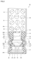
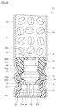
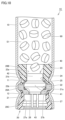
- FIG. 1 is a schematic diagram of a cylinder-shaped gas generator according to a first embodiment
- 2 is an enlarged cross-sectional view of the vicinity of an igniter of the cylinder-shaped gas generator shown in FIG. 1.
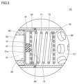
- 2 is an enlarged cross-sectional view of the vicinity of a partition member of the cylinder-shaped gas generator shown in FIG. 1.
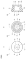
- FIG. 2 is a perspective view of a second holder shown in FIG. 1 .
- 2A to 2C are a plan view, a bottom view and a cross-sectional view of the second holder shown in FIG. 1 .
- 3A to 3C are schematic cross-sectional views showing a procedure for assembling a holder assembly in the cylinder-shaped gas generator shown in FIG.
- FIG. 2 is a cross-sectional view of the cylinder-shaped gas generator shown in FIG. 1 .
- 2 is an enlarged cross-sectional view of a main portion of the cylinder-shaped gas generator shown in FIG. 1 .
- 11 is an enlarged cross-sectional view of the vicinity of an igniter of a cylinder-shaped gas generator according to a second embodiment.
- FIG. FIG. 11 is an enlarged cross-sectional view of the vicinity of an igniter of a cylinder-shaped gas generator according to a third embodiment.
- FIG. 10 is an enlarged cross-sectional view of the vicinity of an igniter of a cylinder-shaped gas generator according to a fourth embodiment.
- FIG. 1 is a schematic diagram of a cylinder-shaped gas generator according to an embodiment.
- Figs. 2 and 3 are enlarged sectional views of the vicinity of an igniter and the vicinity of a partition member of the cylinder-shaped gas generator shown in Fig. 1, respectively.
- a cylinder-shaped gas generator 1A according to this embodiment will be described with reference to Figs. 1 to 3.
- the cylinder-type gas generator 1A has a long, cylindrical outer shape and a long, approximately cylindrical housing with one axial end and the other end closed.
- the housing includes a housing body 10, a holder assembly 20, a blocking member 30, and a partition member 50, of which the housing body 10, the holder assembly 20, and the blocking member 30 define the outer shell of the housing.
- a combustion chamber S1 which houses the gas generating agent 60, autoignition agent 61, and coil spring 70, which are among the above-mentioned internal components
- a filter chamber S2 which houses the filter 80.
- the holder assembly 20 includes a first holder 20A made of metal, a second holder 20B made of resin, and a third holder 20C made of resin.
- the first holder 20A is a member that mainly holds the igniter 40
- the second holder 20B functions mainly as a directional member
- the third holder 20C is a member that mainly constitutes a female connector. Details of the holder assembly 20 will be explained later.
- the housing body 10 constitutes the peripheral wall of the housing and is made of a long cylindrical member with openings formed at both axial ends.
- the holder assembly 20 has the first holder 20A, the second holder 20B, and the third holder 20C, and when viewed as a whole, is made of a roughly cylindrical member with a hollow portion extending in a direction parallel to the axial direction of the housing body 10.
- the blocking member 30 is made of a roughly disk-shaped member.
- the housing body 10 may be made of a metal member such as stainless steel, iron steel, aluminum alloy, or stainless alloy, or may be made of a press-formed product formed into a cylindrical shape by pressing a rolled steel plate such as SPCE.
- the housing body 10 may also be made of an electric resistance welded pipe such as STKM.
- the housing body 10 when the housing body 10 is made from a pressed rolled steel plate or an electric resistance welded pipe, it can be formed more cheaply and easily than when using metal components such as stainless steel or steel, and the weight can be significantly reduced.
- the first holder 20A of the holder assembly 20 and the blocking member 30 are made of metal members such as stainless steel, steel, aluminum alloy, stainless steel alloy, etc.
- the holder assembly 20 is fixed to the housing body 10 so as to close one open end in the axial direction of the housing body 10. Specifically, with the holder assembly 20 inserted into the one open end of the housing body 10, a predetermined position of the housing body 10 is reduced in diameter radially inward toward the holder assembly 20, and another predetermined position of the housing body 10 is reduced in diameter radially inward toward the holder assembly 20, thereby crimping and fixing the holder assembly 20 to the housing body 10. As a result, one axial end of the housing is formed by the holder assembly 20.
- the blocking member 30 is fixed to the housing body 10 so as to block the other axial open end of the housing body 10. Specifically, the blocking member 30 is inserted into the other open end of the housing body 10, with one axial end face of the blocking member 30 abutting against the filter 80, and a predetermined position of the housing body 10 is reduced in diameter radially inward toward the vicinity of the other axial end face of the blocking member 30, thereby crimping and fixing the blocking member 30 to the housing body 10. As a result, the other axial end of the housing is formed by the blocking member 30.
- crimping fixations are called eight-way crimping, which reduces the diameter of the housing body 10 radially inward in a substantially uniform manner.
- the housing body 10 is provided with a first crimping portion 11 and a second crimping portion 12 for fixing the holder assembly 20, and a third crimping portion 13 for fixing the blocking member 30. This brings the housing body 10 into direct contact with the holder assembly 20 and the blocking member 30, respectively, preventing gaps from occurring between them.
- the fixing of the holder assembly 20 to the housing body 10 will be explained in more detail later.
- the assembly structure of the blocking member 30 to the housing main body 10 is not limited to the above-mentioned assembly structure, and other assembly structures may be adopted.
- the housing main body 10 and the blocking member 30 may not be separate bodies, but may be constructed as a single member having a cylindrical shape with a bottom.
- the igniter 40 is supported by the holder assembly 20 and is attached to the above-mentioned one end in the axial direction of the housing.
- the igniter 40 is for burning the gas generating agent 60, and is installed so as to face the space inside the housing.
- the igniter 40 is used to generate a flame and is also called a squib.
- the igniter 40 includes a base 41, an ignition portion 42, and a pair of terminal pins 43.
- the base 41 is a portion that holds the ignition portion 42 and the pair of terminal pins 43, and at least one of the pair of terminal pins 43 is inserted into the base 41.
- the pair of terminal pins 43 are used to electrically connect the cylinder-shaped gas generator 1A to an external control unit (not shown) of a vehicle or the like.
- the ignition unit 42 contains an ignition charge that ignites and burns to generate a flame when activated, and a resistor (bridge wire) for igniting the ignition charge.
- a pair of terminal pins 43 are connected to the ignition unit 42 to ignite the ignition charge.
- the ignition unit 42 includes a squib cup formed in a cup shape, the resistor described above is attached so as to connect the tips of a pair of terminal pins 43 inserted into the squib cup, and an ignition charge is loaded into the squib cup so as to surround the resistor or be adjacent to the resistor.
- an ignition charge may be loaded into the ignition unit 42 as necessary.
- the resistor generally uses a nichrome wire or a resistance wire made of an alloy containing platinum and tungsten
- the ignition charge generally uses ZPP (zirconium potassium perchlorate), ZWPP (zirconium tungsten potassium perchlorate), lead tricinate, etc.
- the transfer charge may use a composition made of a metal powder/oxidizer such as B/KNO 3 , B/NaNO 3 , Sr(NO 3 ) 2 , a composition made of titanium hydride/potassium perchlorate, or a composition made of B/5-aminotetrazole/potassium nitrate/molybdenum trioxide.
- a predetermined amount of current flows through the resistor via the terminal pin 43.
- Joule heat is generated in the resistor, and the ignition charge begins to burn.
- the high-temperature thermal particles generated by the combustion split open the squib cup that contains the ignition charge.
- the time from when the current flows through the resistor to when the igniter 40 is activated is generally less than 2 milliseconds when nichrome wire is used for the resistor.
- the igniter 40 is fixed to the holder assembly 20 with its ignition part 42 protruding further toward the combustion chamber S1 than the base part 41, and a part of it being disposed inside the hollow part of the holder assembly 20.
- the igniter 40 is fixed to the holder assembly 20 with its ignition part 42 located on the combustion chamber S1 side, and its terminal pin 43 located on the opposite side to the combustion chamber S1 side.
- a seal member 28 made of an O-ring or the like is interposed at a predetermined position between the holder assembly 20 and the igniter 40, and the gap between the holder assembly 20 and the igniter 40 is filled with the seal member 28, thereby sealing the gap.
- a partition member 50 that constitutes part of the housing as described above is disposed at a predetermined position in the space inside the housing.
- the partition member 50 is a member that divides the space inside the housing in the axial direction into a combustion chamber S1 and a filter chamber S2.
- the partition member 50 has a cylindrical shape with a bottom, and is made of a metal member such as stainless steel, iron or steel, aluminum alloy, or stainless alloy.
- the partition member 50 has a flat partition wall portion 51 arranged perpendicular to the axial direction of the housing body 10, and a cylindrical annular wall portion 52 standing from the periphery of the partition wall portion 51 toward the combustion chamber S1.
- the partition member 50 is arranged so that the outer main surface of the partition wall portion 51 abuts against the filter 80, and the outer peripheral surface of the annular wall portion 52 abuts against the inner peripheral surface of the housing body 10.
- the partition wall portion 51 has a score 51a on its main surface that contacts the filter 80.
- the score 51a is for the purpose of causing the partition wall portion 51 to break and form an opening as the internal pressure of the combustion chamber S1 increases due to the combustion of the gas generating agent 60, and is composed of, for example, a number of grooves arranged radially and intersecting each other.
- the score 51a is provided in the portion of the filter 80 that faces the hollow portion 81.
- the partition member 50 is assembled by being inserted into the housing body 10 and then joined to the housing body 10. More specifically, the partition member 50 is pressed into the interior of the housing body 10, and is fixed to the housing body 10 by joining the annular wall portion 52 of the partition member 50 to the housing body 10 at or near the contact portion between them, for example by welding.
- a weld 90 extending circumferentially around the housing is provided in the portion of the housing corresponding to the portion into which the partition member 50 is inserted, and the gap between the housing body 10 and the partition member 50 is filled by this weld 90. This means that the gap is sealed by the weld 90, making it possible to ensure airtightness in that portion.
- electron beam welding, laser welding, resistance welding, etc. can be suitably used to weld the housing body 10 and the partition member 50 together.
- the assembly structure of the partition member 50 to the housing body 10 is not limited to the above-mentioned press-fit and welding structure, and other assembly structures may be used. In this case, airtightness between the housing body 10 and the partition member 50 can be ensured by providing an O-ring or the like at an appropriate position.
- the space inside the housing is sandwiched between the holder assembly 20 and the partition member 50 (i.e., the combustion chamber S1), in which a gas generating agent 60, an autoignition agent 61, and a coil spring 70 are arranged.
- the partition member 50 i.e., the combustion chamber S1
- a gas generating agent 60, an autoignition agent 61, and a coil spring 70 are arranged.
- the coil spring 70 is disposed on the side of the combustion chamber S1 where the partition member 50 is located, and the gas generating agent 60 is disposed between the holder assembly 20 and the coil spring 70.
- the autoignition agent 61 is disposed between the partition member 50 and the coil spring 70 so as to abut against the partition member 50.
- Gas generating agent 60 is an agent that generates gas by being ignited and burned by thermal particles generated by the operation of igniter 40. It is preferable to use a non-azide gas generating agent as gas generating agent 60, and gas generating agent 60 is generally configured as a molded body containing fuel, an oxidizer, and an additive.
- the fuel may be, for example, a triazole derivative, a tetrazole derivative, a guanidine derivative, an azodicarbonamide derivative, a hydrazine derivative, or a combination of these.
- a triazole derivative e.g., a tetrazole derivative
- a guanidine derivative e.g., a tetrazole derivative
- an azodicarbonamide derivative e.g., a hydrazine derivative
- nitroguanidine, guanidine nitrate, cyanoguanidine, 5-aminotetrazole, etc. are preferably used.
- oxidizing agent for example, basic metal salts such as basic copper nitrate and basic copper carbonate, perchlorates such as ammonium perchlorate and potassium perchlorate, and nitrates containing cations selected from alkali metals, alkaline earth metals, transition metals, and ammonia are used.
- nitrate for example, sodium nitrate, potassium nitrate, etc. are preferably used.
- Additives include binders, slag formers, and combustion control agents.
- Suitable binders include organic binders such as metal salts of carboxymethylcellulose and stearates, and inorganic binders such as synthetic hydrotalcite and acid clay.
- Suitable slag formers include silicon nitride, silica, and acid clay.
- Suitable combustion control agents include metal oxides, ferrosilicon, activated carbon, and graphite.
- the shape of the molded body of the gas generating agent 60 can be granular, pellet-like, cylindrical, or disk-like, and there are various other shapes.
- perforated molded bodies having through holes inside the molded body for example, single-hole cylindrical or multi-hole cylindrical shapes
- These shapes are preferably selected appropriately according to the specifications of the airbag device in which the cylindrical gas generator 1A is incorporated, and it is preferable to select the optimal shape according to the specifications, such as a shape in which the gas generation rate changes over time when the gas generating agent 60 is burned.
- the coil spring 70 is provided for the purpose of preventing the gas generating agent 60, which is made of a molded body, from being crushed by vibration, etc., and has a spring portion 71 formed by bending a metal wire and a pair of pressure portions 72 located on both ends of the spring portion 71.
- the spring portion 71 is a generally cylindrical portion in which metal wire is wound in a spiral shape.
- one of the pair of pressing portions 72 is provided at one end of the spring portion 71, and the other is provided at the other end of the spring portion 71.
- the pair of pressing portions 72 are configured to have a generally disk-like shape overall, for example, by arranging the metal wires generally parallel to each other at a predetermined interval, or by arranging the metal wires in a spiral shape at a predetermined interval.
- One of the pair of pressing portions 72 is in contact with the gas generating agent 60, and the other is in contact with the auto-ignition agent 61.
- the coil spring 70 is sandwiched between the auto-ignition agent 61 and the gas generating agent 60, and is thus in a compressed state. Therefore, the gas generating agent 60 is elastically biased toward the holder assembly 20 by the coil spring 70, which prevents the gas generating agent 60 from moving inside the combustion chamber S1. Therefore, by configuring it in this way, it is possible to prevent the gas generating agent 60, which is made of a molded body, from being crushed by vibration or the like.
- the coil spring 70 when the coil spring 70 is assembled, the coil spring 70 is sandwiched between the autoignition agent 61 and the gas generating agent 60 and compressed, so that the dimensional variations of the various components housed inside the housing can be absorbed by the coil spring 70.
- the autoignition agent 61 consists of pellets formed into a flattened, generally cylindrical shape.
- the autoignition agent 61 is positioned on the opposite side of the coil spring 70 from the side on which the gas generating agent 60 is located (i.e., the filter 80 side), and is held between the bulkhead portion 51 of the partition member 50 and the coil spring 70. As a result, the autoignition agent 61 is separated from the gas generating agent 60 by the coil spring 70.
- the autoignition agent 61 is an agent that ignites automatically without the operation of the igniter 40. More specifically, the autoignition agent 61 spontaneously ignites at a lower temperature than the gas generating agent 60, and is intended to prevent abnormal operation of the cylinder-shaped gas generator 1A from being induced by external heating in the unlikely event of a fire or other accident occurring in a vehicle or the like equipped with an airbag device incorporating the cylinder-shaped gas generator 1A.
- a filter 80 is disposed in the space inside the housing, which is the space between the blocking member 30 and the partition member 50 (i.e., the filter chamber S2).
- the filter 80 is a cylindrical member having a hollow portion 81 extending in a direction parallel to the axial direction of the housing body 10, with one axial end face abutting against the blocking member 30 and the other axial end face abutting against the bulkhead portion 51 of the partition member 50.
- the filter 80 functions as a cooling means for cooling the gas by removing the high temperature heat of the gas generated by the combustion of the gas generating agent 60 as it passes through the filter 80, and also functions as a removal means for removing slag (residue) and the like contained in the gas.
- the filter 80 made of a cylindrical member as described above, the flow resistance of the gas flowing through the filter chamber S2 during operation is kept low, making it possible to achieve efficient gas flow.
- the filter 80 can be preferably made of an assembly of metal wire or metal mesh material made of stainless steel, iron or steel. Specifically, it can be made of knitted wire mesh, plain woven wire mesh, an assembly of crimped woven metal wire, or any of these compressed by a press.
- a perforated metal sheet rolled up can be used as the filter 80.
- the perforated metal sheet can be, for example, expanded metal, which is a metal sheet cut in a zigzag pattern and then expanded to form holes and processed into a mesh-like shape, or hook metal, which is a metal sheet that has holes drilled into it and has burrs formed around the edges of the holes that are then flattened by crushing them.
- the housing body 10 in the portion that defines the filter chamber S2 has multiple gas outlets 14 arranged along the circumferential and axial directions. These multiple gas outlets 14 are for directing the gas that has passed through the filter 80 to the outside of the housing.
- the collision is detected by a collision detection means provided separately in the vehicle, and based on this, the igniter 40 is activated by the passage of electricity from a control unit provided separately in the vehicle.
- the pressure inside the ignition section 42 rises due to the combustion of the ignition charge or, in addition, the transfer charge, which causes the squib cup of the ignition section 42 to split open, and the thermal particles generated by the combustion of the ignition charge or, in addition, the transfer charge flow out to the outside of the ignition section 42.
- the thermal particles that reach the gas generating agent 60 combust the gas generating agent 60, which generates a large amount of gas inside the combustion chamber S1.
- the pressure in the combustion chamber S1 rises, and when the internal pressure of the combustion chamber S1 reaches a predetermined pressure, a fracture occurs in the portion of the partition member 50 where the score 51a is provided.
- an opening is formed in the partition member 50 in the portion facing the cavity 81 of the filter 80, and the combustion chamber S1 and the filter chamber S2 are in communication with each other via the opening.
- the gas generated in the combustion chamber S1 flows into the filter chamber S2 through an opening formed in the partition member 50.
- the gas that flows into the filter chamber S2 flows axially through the cavity 81 of the filter 80, then changes direction toward the radial direction and flows through the inside of the filter 80.
- the filter 80 removes heat and cools the gas, and the filter 80 removes slag contained in the gas.
- the gas that has passed through the filter 80 is then ejected to the outside of the housing through the gas ejection port 14 provided in the housing body 10.
- the ejected gas is introduced into the airbag provided adjacent to the cylindrical gas generator 1A, and inflates and deploys the airbag.
- the autoignition agent 61 is burned together with the gas generating agent 60 when it is burned.
- FIGS. 4(A) and 4(B) are perspective views of the second holder of the holder assembly of the cylinder-shaped gas generator of this embodiment.
- Figs. 5(A) and 5(B) are plan and bottom views of the second holder, respectively
- Fig. 5(C) is a cross-sectional view taken along line VC-VC shown in Figs. 5(A) and 5(B).
- Figs. 6(A) to 6(C) are schematic cross-sectional views showing, in stages, the assembly procedure of the holder assembly in the cylinder-shaped gas generator of this embodiment and the assembly procedure of the holder assembly to the housing body.
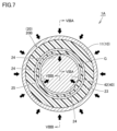
- Fig. 7 is a cross-sectional view taken along line VII-VII shown in Fig. 2, and Figs.
- FIG. 8(A) and 8(B) are enlarged cross-sectional views of the main parts taken along lines VIIIA-VIIIA and VIIIB-VIIIB shown in Fig. 7, respectively.
- Figures 4(A) to 8(B) and the aforementioned Figure 2 we will explain the detailed structure near the igniter 40 in the cylinder-shaped gas generator 1A according to this embodiment.
- the igniter 40 is supported by the holder assembly 20 that is mounted to the housing body 10 so as to close the aforementioned one axial end of the housing, thereby mounting the igniter 40 to the one axial end of the housing.
- the holder assembly 20 includes a first holder 20A made of metal, a second holder 20B made of resin, and a third holder 20C made of resin, and the holder assembly 20 is fixed to the housing body 10 by a first crimping portion 11 and a second crimping portion 12 provided at predetermined positions on the housing body 10.
- the first holder 20A is composed of a flat, approximately disk-shaped member having a through-hole extending axially in the center, and includes a cylindrical first body 21 and an annular protrusion 22 that protrudes outward from the outer periphery of the first body 21.
- the first holder 20A is inserted into the housing body 10 so that its axial direction is parallel to the axial direction of the housing body 10.
- the through-hole provided in the first holder 20A defines a part of the above-mentioned hollow portion of the holder assembly 20, and the annular protrusion 22 protrudes outward from the first body 21 along the radial direction of the housing body 10.
- the above-mentioned annular protrusion 22 is provided at the end of the first body 21 on the combustion chamber S1 side.
- the first holder 20A is a member for receiving and holding the igniter 40, and has a concave first housing portion 21a at its axial end on the combustion chamber S1 side to receive the igniter 40.
- This first housing portion 21a is connected to a through-hole provided in the first holder 20A, and defines part of the above-mentioned hollow portion of the holder assembly 20.
- a crimping portion 21b is provided at the end on the combustion chamber S1 side of the first holder 20A so as to surround the first housing portion 21a.
- the crimping portion 21b is a portion for crimping and fixing the igniter 40 to the first holder 20A.
- the igniter 40 is fixed to the first holder 20A with its base 41 housed in the first housing portion 21a of the first holder 20A. Specifically, the base 41 is inserted into the first housing portion 21a of the first holder 20A and the base 41 is secured to the bottom surface of the first housing portion 21a. In this state, the crimping portion 21b provided on the first holder 20A is bent, thereby fixing the igniter 40 to the first holder 20A. In this way, the igniter 40 is held by the first holder 20A.
- the sealing member 28 which is made of an O-ring or the like as described above, is interposed between the first holder 20A and the igniter 40. Specifically, the sealing member 28 is disposed on the outer edge of the bottom surface of the first housing portion 21a of the first holder 20A. As a result, the sealing member 28 is sandwiched and compressed between the first holder 20A and the igniter 40 by the pressing force generated by the crimping of the crimping portion 21b described above, thereby sealing the gap that occurs between the holder assembly 20 and the igniter 40.
- the second holder 20B is composed of a generally cylindrical member having a second storage portion 23a in the form of a generally through hole extending axially in the center thereof, and includes a cylindrical second body portion 23 and a lid portion 26 provided to cover one axial end of the second storage portion 23a.
- the second holder 20B is disposed on the combustion chamber S1 side as viewed from the first holder 20A, and is positioned adjacent to the first holder 20A.
- the second holder 20B is inserted into the housing body 10 so that its axial direction is parallel to the axial direction of the housing body 10.
- the second accommodating portion 23a provided in the second holder 20B defines a portion of the above-mentioned hollow portion of the holder assembly 20.
- the second housing portion 23a provided in the second holder 20B houses the ignition portion 42 of the igniter 40.
- the second holder 20B is positioned so as to surround the periphery of the ignition portion 42 of the igniter 40 held by the first holder 20A, and as a result, the portion of the second body portion 23 of the second holder 20B that is closer to the first holder 20A is positioned so as to surround the peripheral surface of the ignition portion 42.
- the above-mentioned lid portion 26 is provided at the axial end of the second body 23 opposite the first holder 20A side so as to be located a predetermined distance away from the ignition portion 42.
- the second body 23 extends along the axial direction of the housing body 10 so as to be located protruding further toward the combustion chamber S1 side than the ignition portion 42, and by providing the lid portion 26 at the axial end on the tip side, the lid portion 26 is located a predetermined distance away from the ignition portion 42.
- the lid portion 26 is provided with a plurality of openings 26a, and the maximum outer dimension of each of these openings 26a when viewed along the axial direction of the housing body 10 is configured to be smaller than the minimum outer dimension of the gas generating agent 60. More specifically, in this embodiment, one circular opening 26a is provided in the center of the lid portion 26, and three openings 26a in the shape of curved elongated holes are provided surrounding it, so that the maximum outer dimension of each opening 26a is configured to be smaller than the minimum outer dimension of the gas generating agent 60.
- the second storage section 23a which is located on the opposite side of the base section 41 from the ignition section 42, is essentially closed by the lid section 26 at a position a predetermined distance away from the ignition section 42, preventing the gas generating agent 60 from entering the second storage section 23a and is spaced apart so that the gas generating agent 60 is positioned at a distance from the ignition section 42.
- the second holder 20B functions as a directional member that fills the gap between the ignition portion 42 of the igniter 40 and the housing body 10, thereby providing directionality to the direction of travel of the thermal particles generated in the ignition portion 42 when the cylinder-shaped gas generator 1A is activated, and in particular, the second body portion 23 of the second holder 20B has this function.
- the second holder 20B also functions as a spacer to maintain a predetermined appropriate distance between the ignition part 42 and the gas generating agent 60; in particular, the lid part 26 of the second holder 20B has this function.
- a first annular step portion 23b is provided at the axial end portion of the second holder 20B located on the first holder 20A side, formed by cutting out a part of the second body portion 23.
- This first annular step portion 23b is provided on the inner edge of the end portion of the second body portion 23 on the first holder 20A side.
- the crimping portion 21b of the first holder 20A is fitted into the first annular step portion 23b provided on the second holder 20B.
- the third holder 20C is made of a substantially cylindrical member having a third housing portion 27a in the form of a through hole extending axially in the center thereof, and includes a cylindrical third body portion 27.
- the third holder 20C is disposed on the opposite side of the combustion chamber S1 from the first holder 20A, and is positioned adjacent to the first holder 20A.
- the third holder 20C is inserted into the housing body 10 so that its axial direction is parallel to the axial direction of the housing body 10.
- the third housing portion 27a provided in the third holder 20C defines a portion of the above-mentioned hollow portion of the holder assembly 20.
- the third housing portion 27a provided in the third holder 20C houses a pair of terminal pins 43 of the igniter 40.
- the third holder 20C is positioned so as to surround the pair of terminal pins 43 of the igniter 40 held by the first holder 20A, and thus the pair of terminal pins 43 of the igniter 40 are disposed inside the third holder 20C.
- the third housing portion 27a constitutes a portion for receiving the connection connector of the harness described above.
- the igniter 40 in the cylinder-type gas generator 1A, the igniter 40 must be electrically connected to an external control unit of the vehicle or the like, and a harness is usually used for this electrical connection.
- a male connector is attached to the end of this harness, and the third holder 20C must be provided with a female connector that can be connected to this male connector.
- the third housing portion 27a provided in the third holder 20C constitutes this female connector.
- the male connector of the harness is inserted into the third housing portion 27a, which functions as a female connector, electrical continuity is established between the core wire of the harness and the terminal pin 43. This allows the igniter 40 to be connected to a control unit of the vehicle, etc.
- a second annular step 27b is provided at the axial end of the third holder 20C located on the first holder 20A side, and is formed by cutting out a part of the third body 27.
- This second annular step 27b is provided on the inner edge of the end of the third body 27 on the first holder 20A side.
- the axial end of the first body 21 of the first holder 20A on the opposite side to the combustion chamber S1 side is fitted into the second annular step 27b provided on the third holder 20C.
- the materials of the second holder 20B and the third holder 20C described above are not particularly limited, but suitable materials include nylon-based resins such as nylon 6, nylon 66, and those filled with glass filler, polyacetal (POM) resin, polycarbonate (PC) resin, polyphenylene sulfide (PPS) resin, polybutylene terephthalate (PBT) resin, etc.
- suitable materials include nylon-based resins such as nylon 6, nylon 66, and those filled with glass filler, polyacetal (POM) resin, polycarbonate (PC) resin, polyphenylene sulfide (PPS) resin, polybutylene terephthalate (PBT) resin, etc.
- the second holder 20B and the third holder 20C may be made of the same type of material or different types of materials.
- the second holder 20B can be provided with the function of a directional member, as described above. That is, the gap between the ignition part 42 and the housing body 10 is substantially filled by the second holder 20B, and the degree of opening of the squib cup during operation of the cylinder-shaped gas generator 1A is intentionally limited, so that an opening is mainly formed at the tip of the squib cup located on the gas generating agent 60 side, and the traveling direction of the thermal particles generated in the ignition part 42 is narrowed to the axial direction of the housing body 10. Therefore, it is possible to efficiently guide the thermal particles generated in the ignition part 42 to the gas generating agent 60, and it is possible to reduce the amount of gas generating agent 60 required to obtain the desired gas output.
- the gap between the ignition portion 42 and the housing body 10 is essentially filled by the second holder 20B, it is possible to reduce the volume of the combustion chamber S1 compared to when this portion is not filled, and this promotes an increase in the internal pressure of the combustion chamber S1 when the cylinder-type gas generator 1A is activated. Therefore, in this respect as well, it is possible to efficiently burn the gas generating agent 60, and it is possible to reduce the amount of gas generating agent 60 required to obtain the desired gas output.
- the cover portion 26 is provided on the second holder 20B, so that the second holder 20B functions as a spacer for maintaining the distance between the ignition portion 42 and the gas generating agent 60 at a predetermined appropriate distance. Therefore, by configuring in this manner, individual differences in the distance between the igniter 40 and the gas generating agent 60 are less likely to occur, and it becomes possible to stably obtain the desired gas output when the cylinder-shaped gas generator 1A is activated.
- the holder assembly 20 and the igniter 40 are first assembled to form a sub-assembly of the holder assembly 20 and the igniter 40, and then the sub-assembled holder assembly 20 and igniter 40 (hereinafter referred to as the igniter assembly) are assembled to the housing body 10.
- a first holder 20A is prepared to which an igniter 40 and a sealing member 28 are pre-assembled, and the second holder 20B and the third holder 20C are assembled to the first holder 20A to produce the igniter assembly.
- the second holder 20B is assembled to the first holder 20A in the direction of the arrow DR1 in the figure so that the ignition part 42 is accommodated in the second accommodation part 23a.
- the crimping part 21b of the first holder 20A is fitted into the first annular step part 23b provided on the second holder 20B, and the ignition part 42 is pressed into the second body part 23 of the second holder 20B.
- the pressing of the ignition part 42 into the second body part 23 will be described in detail later. This fixes the second holder 20B to the first holder 20A.
- the third holder 20C is assembled to the first holder 20A in the direction of the arrow DR2 in the figure so that the pair of terminal pins 43 are accommodated in the third accommodating portion 27a. At this time, the axial end of the first holder 20A is fitted and pressed into the second annular step portion 27b provided on the third holder 20C. This fixes the third holder 20C to the first holder 20A.
- the igniter assembly produced by assembling the first holder 20A, the second holder 20B, the third holder 20C, the igniter 40, and the seal member 28 is inserted and pressed into the axial end of the housing body 10 in the direction of the arrow DR3 in the figure.
- the outer peripheral surfaces corresponding to the maximum outer diameter portions of the first holder 20A, the second holder 20B, and the third holder 20C are brought into pressure contact with the inner peripheral surface of the housing body 10, and the igniter assembly inserted into the housing body 10 is positioned and arranged at a predetermined position inside the housing body 10, so that the igniter assembly is held by the housing body 10 at the predetermined position.
- the housing body 10 is narrowed radially inward at a predetermined position, thereby crimping and fixing the igniter assembly to the housing body 10.
- the housing body 10 is reduced in diameter in the direction of arrow A shown in the figure at a position corresponding to the portion of the second holder 20B adjacent to the first holder 20A, and is reduced in diameter in the direction of arrow B shown in the figure at a position corresponding to the portion of the third holder 20C adjacent to the first holder 20A.
- the reduction in diameter at these two locations on the housing body 10 is both the above-mentioned eight-way crimping type crimping, and is performed simultaneously using a dedicated crimping machine.
- the annular protrusion 22 of the first holder 20A is sandwiched in the axial direction of the housing body 10 by the housing body 10 which has been reduced in diameter at the two locations.
- the annular protrusion 22 is immovably held by the first crimping portion 11 and the second crimping portion 12, which are the two locations of the housing body 10 where the diameter has been reduced, and the igniter assembly including the holder assembly 20 is crimped and fixed to the housing body 10.
- the first crimping portion 11 is reduced in diameter so that its inner circumferential surface is in pressure contact with the outer circumferential surface of the second body 23 of the second holder 20B
- the second crimping portion 12 is reduced in diameter so that its inner circumferential surface is in pressure contact with the outer circumferential surface of the third body 27 of the third holder 20C.
- the ignition portion 42 is pressed into the second body portion 23 of the second holder 20B.
- the second holder 20B is not sufficiently fixed to the first holder 20A, there is a possibility that the second holder 20B will become misaligned when the igniter assembly is later crimped and fixed to the housing body 10 described above.
- the housing body 10 when the igniter assembly is crimped to the housing body 10, the housing body 10 is reduced in diameter so that the inner peripheral surface of the housing body 10 where the first crimping portion 11 is formed is brought into pressure contact with the outer peripheral surface of the second body 23 of the second holder 20B, and a compressive force is also applied locally to the second body 23 at that portion.
- a compressive force also acts on the ignition portion 42 via the second body 23, and there is a risk that the ignition portion 42 will be significantly deformed due to this compressive force. Therefore, when the igniter assembly is crimped to the housing body 10, it is necessary to suppress deformation of the ignition portion 42 as much as possible.
- the cylinder-type gas generator 1A it is possible to press-fit the ignition portion 42 into the second body portion 23 while minimizing deformation of the ignition portion 42 due to this, and it is also possible to minimize deformation of the ignition portion 42 when the igniter assembly is crimped and fixed to the housing body 10.
- the mechanism is described in detail below.
- a plurality of protrusions 24 are provided on the inner circumferential surface of the second body 23 of the second holder 20B, which is compressed radially inward by pressure contact with the first crimping portion 11, and which faces the outer circumferential surface of the ignition portion 42.
- these plurality of protrusions 24 are positioned in a dotted row along the circumferential direction of the second body 23, and protrude toward the ignition portion 42.
- the inner diameter of the second holder 20B (i.e., the diameter of the second housing portion 23a) is configured to be slightly larger than the diameter of the ignition portion 42, and the amount of protrusion of the multiple protrusions 24 is adjusted so that when the ignition portion 42 is inserted into the second body portion 23 of the second holder 20B, their tips come into pressure contact with the outer peripheral surface of the ignition portion 42 with a relatively weak force.
- the multiple protrusions 24 are arranged so as not to pinch the axis of the ignition part 42 in a direction perpendicular to the axis.
- the multiple protrusions 24 come into pressure contact with the ignition part 42, so that the directions of the forces applied to the ignition part 42 cross each other (in other words, it is possible to prevent these forces from overlapping in opposite directions on the same straight line), making it possible to more reliably suppress deformation of the ignition part 42.
- these multiple protrusions 24 are evenly spaced along the circumferential direction of the second body 23. This configuration makes it possible to distribute the force applied to the ignition part 42, making it possible to more reliably prevent the ignition part 42 from deforming.
- the multiple protrusions 24 are provided in an odd number evenly spaced along the circumferential direction of the second body 23, and in this embodiment, three of these multiple protrusions 24 are provided evenly spaced along the circumferential direction of the second body 23.
- a groove portion 25 is provided around the second body portion 23 at a radially outer position of the portion of the second body portion 23 of the second holder 20B where the multiple protrusions 24 are provided.
- the groove portion 25 is provided on the axial end surface of the second body portion 23 on the first holder 20A side.
- the rigidity of the portion of the second body 23 where the multiple protrusions 24 are provided can be reduced to a considerable extent, making it possible to reduce the force applied to the ignition part 42 by the multiple protrusions 24 when the ignition part 42 is pressed into the second body 23 and after it has been pressed in. Therefore, deformation of the ignition part 42 can be more reliably prevented while the ignition part 42 is pressed into the second body 23.
- the compression force applied to the second body 23 as the housing body 10 is reduced in diameter is effectively absorbed by the second body 23 by providing the groove 25. Therefore, even when the igniter assembly is crimped to the housing body 10, deformation of the ignition portion 42 can be more reliably suppressed.
- the cylinder-shaped gas generator 1A As described above, by making the cylinder-shaped gas generator 1A according to this embodiment, it is possible to firmly fix the second holder 20B to the first holder 20A by pressing the ignition portion 42 into the second body portion 23 while suppressing deformation of the ignition portion 42, and by providing the first crimping portion 11 and the second crimping portion 12 on the housing main body 10, it is possible to firmly fix the igniter assembly including the first holder 20A, the second holder 20B, the third holder 20C, and the igniter 40, etc., to the housing main body 10.
- the cylinder-type gas generator 1A can be a cylinder-type gas generator that can stably obtain the desired gas output while suppressing increases in manufacturing costs.
- the cover portion 26 is provided on the second holder 20B, which makes it difficult for individual differences to occur in the distance between the igniter 40 and the gas generating agent 60. Therefore, in this respect as well, it is possible to provide a cylinder-type gas generator that can stably obtain the desired gas output.
- the portion of the housing body 10 where the first crimping portion 11 is provided has a shape that is curved in the axial direction of the housing body 10, unlike the portion of the housing body 10 that defines the combustion chamber S1. Therefore, the portion of the housing body 10 where the first crimping portion 11 is provided has inferior strength to the portion of the housing body 10 that defines the combustion chamber S1.
- the inner circumferential surface of the first crimped portion 11 is substantially covered by the second body portion 23 of the second holder 20B, so that the second body portion 23 of the second holder 20B protects the first crimped portion 11 when the cylinder-shaped gas generator 1A is in operation. This also improves the pressure resistance performance of the cylinder-shaped gas generator 1A as a whole.
- FIG. 9 is an enlarged cross-sectional view of the vicinity of the igniter of a cylinder-shaped gas generator according to Embodiment 2.
- cylinder-shaped gas generator 1B according to the present embodiment will be described with reference to Fig. 9.
- the cylinder-shaped gas generator 1B of this embodiment differs in configuration from the cylinder-shaped gas generator 1A of the above-described embodiment 1 only in that the second body portion 23 of the second holder 20B does not have a groove portion 25 (see FIG. 2, etc.), but the other configurations are the same as those of the cylinder-shaped gas generator 1A described above.
- FIG. 10 is an enlarged cross-sectional view of the vicinity of the igniter of a cylinder-shaped gas generator according to Embodiment 3.
- cylinder-shaped gas generator 1C according to the present embodiment will be described with reference to Fig. 10.
- the configuration of the cylinder-shaped gas generator 1C of this embodiment differs from the cylinder-shaped gas generator 1A of the above-described embodiment 1 only in that the second holder 20B does not have a lid portion 26 (see FIG. 2, etc.), but the other configurations are the same as those of the cylinder-shaped gas generator 1A described above.
- FIG. 11 is an enlarged cross-sectional view of the vicinity of the igniter of a cylinder-shaped gas generator according to Embodiment 4.
- a cylinder-shaped gas generator 1D according to the present embodiment will be described.
- the cylinder-shaped gas generator 1D of this embodiment differs from the cylinder-shaped gas generator 1A of the above-described embodiment 1 only in that the second holder 20B does not have a lid portion 26 (see FIG. 2, etc.) and that the second body portion 23 of the second holder 20B is configured to a size that fills only the space between the ignition portion 42 and the housing main body 10; however, the rest of the configuration is the same as the above-described cylinder-shaped gas generator 1A.
- a cylindrical metal housing body including a combustion chamber in which a gas generating agent is accommodated; a holder assembly that is inserted into an axial opening end of the housing body and includes a hollow portion that extends in a direction parallel to the axial direction of the housing body; an igniter including an ignition part loaded with an ignition charge, a terminal pin connected to the ignition part, and a base part through which the terminal pin is inserted and which supports both the ignition part and the terminal pin, at least a part of which is disposed inside the hollow part with the ignition part positioned on the combustion chamber side and the terminal pin positioned on the opposite side to the combustion chamber side; the holder assembly includes a first holder made of metal that receives the base to hold the igniter, and a second holder made of resin that is located on the combustion chamber side as viewed from the first holder and that houses the ignition portion; the first holder includes a cylindrical first body portion defining the hollow portion, and an annular protrusion protruding from the first body portion along a radial
- Appendix 4 4. The gas generator described in any one of appendix 1 to 3, wherein a groove portion is provided around the second body portion at a radially outer position of a portion of the second body portion where the plurality of protrusions are provided.
- Appendix 5 A gas generator as described in any one of appendices 1 to 4, wherein an axial end portion of the second holder located on the first holder side is fixed to the first holder by being fitted into the first holder.
- the holder assembly further includes a third holder made of resin, the third holder being located on an opposite side to the combustion chamber side as viewed from the first holder and capable of receiving a connector to be connected to the terminal pin; the third holder includes a cylindrical third body portion defining the hollow portion, 6.
- the holder assembly is configured by the first metal holder having the main function of holding the igniter, the second resin holder having the main function of a directionality imparting member, and the third resin holder having the main function of forming the female connector portion.
- the first holder and the third holder may be a single member.
- the single member may be made of metal, and may be provided with the female connector portion while having the function of holding the igniter.
- the case where multiple openings are provided in the lid portion of the second holder has been described as an example, but a single opening may be provided in the lid portion.
- the lid portion itself is configured to be thin and fragile, or has scores provided in the lid portion so that it opens due to the combustion of the ignition charge when the cylindrical gas generator is activated, it is not necessarily necessary to provide an opening in the lid portion.
- the present invention has been described as being applied to a cylindrical gas generator incorporated in a side airbag device, but the application of the present invention is not limited to this, and the present invention can also be applied to cylindrical gas generators incorporated in curtain airbag devices, knee airbag devices, seat cushion airbag devices, etc., and so-called T-shaped gas generators that have an elongated outer shape like a cylindrical gas generator.
- 1A-1D Cylinder-type gas generator
- 10 Housing body
- 11 First crimped portion
- 12 Second crimped portion
- 13 Third crimped portion
- 14 Gas outlet
- 20 Holder assembly
- 20A First holder
- 20B Second holder
- 20C Third holder
- 21 First body portion
- 21a First storage portion
- 21b Crimped portion
- 22 Annular protrusion
- 23 Second body portion
- 23a Second storage portion
- 23b First annular step portion
- 24 Protrusion portion
- 25 Groove portion
- 26 Lid portion
- 26a Opening , 27 third body portion, 27a third housing portion, 27b second annular step portion, 28 sealing member, 30 blocking member, 40 igniter, 41 base portion, 42 ignition portion, 43 terminal pin
- 50 partition member 51 bulkhead portion, 51a score, 52 annular wall portion
- 60 gas generating agent
- 70 coil spring 71 spring portion
- 72 pressing portion 80 filter
Landscapes
- Physics & Mathematics (AREA)
- Fluid Mechanics (AREA)
- Engineering & Computer Science (AREA)
- Mechanical Engineering (AREA)
- Chemical & Material Sciences (AREA)
- Organic Chemistry (AREA)
- Chemical Kinetics & Catalysis (AREA)
- Air Bags (AREA)
- Feeding, Discharge, Calcimining, Fusing, And Gas-Generation Devices (AREA)
Abstract
Description
図1は、実施の形態に係るシリンダ型ガス発生器の概略図である。図2および図3は、それぞれ図1に示すシリンダ型ガス発生器の点火器近傍の拡大断面図および仕切り部材近傍の拡大断面図である。まず、これら図1ないし図3を参照して、本実施の形態に係るシリンダ型ガス発生器1Aの構成について説明する。
図9は、実施の形態2に係るシリンダ型ガス発生器の点火器近傍の拡大断面図である。以下、この図9を参照して、本実施の形態に係るシリンダ型ガス発生器1Bについて説明する。
図10は、実施の形態3に係るシリンダ型ガス発生器の点火器近傍の拡大断面図である。以下、この図10を参照して、本実施の形態に係るシリンダ型ガス発生器1Cについて説明する。
図11は、実施の形態4に係るシリンダ型ガス発生器の点火器近傍の拡大断面図である。以下、この図11を参照して、本実施の形態に係るシリンダ型ガス発生器1Dについて説明する。
上述した実施の形態1ないし4において開示したガス発生器の特徴的な構成を要約すると、以下のとおりとなる。
ガス発生剤が収容された燃焼室を内部に含む筒状の金属製のハウジング本体と、
上記ハウジング本体の軸方向の開口端に内挿され、上記ハウジング本体の軸方向と平行な方向に沿って延びる中空部を含むホルダ組立体と、
点火薬が装填された点火部、上記点火部に接続された端子ピン、ならびに、上記端子ピンが挿通されるとともに上記点火部および上記端子ピンの双方を支持する基部を含み、上記点火部が上記燃焼室側に位置しかつ上記端子ピンが上記燃焼室側とは反対側に位置した状態で上記中空部の内部に少なくともその一部が配置された点火器とを備え、
上記ホルダ組立体は、上記基部を受け入れることで上記点火器を保持する金属製の第1ホルダと、上記第1ホルダから見て上記燃焼室側に位置するとともに上記点火部を収容する樹脂製の第2ホルダとを有し、
上記第1ホルダは、上記中空部を規定する筒状の第1胴部と、上記ハウジング本体の径方向に沿って上記第1胴部から突出する環状突部とを含み、
上記第2ホルダは、上記中空部を規定する筒状の第2胴部を含み、
上記ハウジング本体は、径方向内側に向けて縮径した第1かしめ部と、上記第1かしめ部から見て上記開口端側に位置し、径方向内側に向けて縮径した第2かしめ部とを有し、
上記第1ホルダは、上記第1かしめ部および上記第2かしめ部によって上記環状突部が上記ハウジング本体の軸方向において挟み込まれることにより、上記ハウジング本体に固定され、
上記第1かしめ部は、上記第2胴部によって覆われているとともに、上記第2胴部の外周面の少なくとも一部に圧接触し、
上記第2胴部のうち、上記第1かしめ部が圧接触することで径方向内側に向けて圧縮させられた部分の内周面であってかつ上記点火部の外周面に面する部分には、上記ハウジング本体の軸方向に沿って見た場合に上記第2胴部の周方向に沿って点列状に位置するとともに上記点火部側に向けて突出する複数の突起部が設けられ、
上記複数の突起部が上記点火部の外周面に当接することにより、上記点火部の外周面と上記第2胴部の内周面との間に間隙部が設けられている、ガス発生器。
上記複数の突起部が、上記点火部の軸線と直交する方向において当該軸線を挟み込まないように配置されている、付記1に記載のガス発生器。
上記複数の突起部が、上記第2胴部の周方向に沿って均等に配置されている、付記1または2に記載のガス発生器。
上記第2胴部のうちの上記複数の突起部が設けられた部分の径方向外側の位置に、上記第2胴部を周回するように溝部が設けられている、付記1から3のいずれかに記載のガス発生器。
上記第1ホルダ側に位置する上記第2ホルダの軸方向端部が、上記第1ホルダに嵌め込まれることで上記第1ホルダに固定されている、付記1から4のいずれかに記載のガス発生器。
上記ホルダ組立体が、上記第1ホルダから見て上記燃焼室側とは反対側に位置するとともに上記端子ピンに接続される接続コネクタを受け入れ可能な樹脂製の第3ホルダをさらに有し、
上記第3ホルダは、上記中空部を規定する筒状の第3胴部を含み、
上記第2かしめ部が、上記第3胴部の外周面の少なくとも一部に圧接触している、付記1から5のいずれかに記載のガス発生器。
上記第1ホルダ側に位置する上記第3ホルダの軸方向端部が、上記第1ホルダに嵌め込まれることで上記第1ホルダに固定されている、付記6に記載のガス発生器。
上述した本発明の実施の形態1ないし4においては、主として点火器を保持する機能を有する金属製の第1ホルダと、主として指向性付与部材としての機能を有する樹脂製の第2ホルダと、主として雌型コネクタ部を構成する樹脂製の第3ホルダとによってホルダ組立体を構成した場合を例示して説明を行なったが、第1ホルダと第3ホルダとは、これらを単一の部材にて兼用することとしてもよい。その場合には、当該単一の部材を金属製とし、これに点火器を保持する機能をもたせつつこれに雌型コネクタ部を設けることとすればよい。
Claims (7)
- ガス発生剤が収容された燃焼室を内部に含む筒状の金属製のハウジング本体と、
前記ハウジング本体の軸方向の開口端に内挿され、前記ハウジング本体の軸方向と平行な方向に沿って延びる中空部を含むホルダ組立体と、
点火薬が装填された点火部、前記点火部に接続された端子ピン、ならびに、前記端子ピンが挿通されるとともに前記点火部および前記端子ピンの双方を支持する基部を含み、前記点火部が前記燃焼室側に位置しかつ前記端子ピンが前記燃焼室側とは反対側に位置した状態で前記中空部の内部に少なくともその一部が配置された点火器とを備え、
前記ホルダ組立体は、前記基部を受け入れることで前記点火器を保持する金属製の第1ホルダと、前記第1ホルダから見て前記燃焼室側に位置するとともに前記点火部を収容する樹脂製の第2ホルダとを有し、
前記第1ホルダは、前記中空部を規定する筒状の第1胴部と、前記ハウジング本体の径方向に沿って前記第1胴部から突出する環状突部とを含み、
前記第2ホルダは、前記中空部を規定する筒状の第2胴部を含み、
前記ハウジング本体は、径方向内側に向けて縮径した第1かしめ部と、前記第1かしめ部から見て前記開口端側に位置し、径方向内側に向けて縮径した第2かしめ部とを有し、
前記第1ホルダは、前記第1かしめ部および前記第2かしめ部によって前記環状突部が前記ハウジング本体の軸方向において挟み込まれることにより、前記ハウジング本体に固定され、
前記第1かしめ部は、前記第2胴部によって覆われているとともに、前記第2胴部の外周面の少なくとも一部に圧接触し、
前記第2胴部のうち、前記第1かしめ部が圧接触することで径方向内側に向けて圧縮させられた部分の内周面であってかつ前記点火部の外周面に面する部分には、前記ハウジング本体の軸方向に沿って見た場合に前記第2胴部の周方向に沿って点列状に位置するとともに前記点火部側に向けて突出する複数の突起部が設けられ、
前記複数の突起部が前記点火部の外周面に当接することにより、前記点火部の外周面と前記第2胴部の内周面との間に間隙部が設けられている、ガス発生器。 - 前記複数の突起部が、前記点火部の軸線と直交する方向において当該軸線を挟み込まないように配置されている、請求項1に記載のガス発生器。
- 前記複数の突起部が、前記第2胴部の周方向に沿って均等に配置されている、請求項2に記載のガス発生器。
- 前記第2胴部のうちの前記複数の突起部が設けられた部分の径方向外側の位置に、前記第2胴部を周回するように溝部が設けられている、請求項1に記載のガス発生器。
- 前記第1ホルダ側に位置する前記第2ホルダの軸方向端部が、前記第1ホルダに嵌め込まれることで前記第1ホルダに固定されている、請求項1に記載のガス発生器。
- 前記ホルダ組立体が、前記第1ホルダから見て前記燃焼室側とは反対側に位置するとともに前記端子ピンに接続される接続コネクタを受け入れ可能な樹脂製の第3ホルダをさらに有し、
前記第3ホルダは、前記中空部を規定する筒状の第3胴部を含み、
前記第2かしめ部が、前記第3胴部の外周面の少なくとも一部に圧接触している、請求項1に記載のガス発生器。 - 前記第1ホルダ側に位置する前記第3ホルダの軸方向端部が、前記第1ホルダに嵌め込まれることで前記第1ホルダに固定されている、請求項6に記載のガス発生器。
Priority Applications (2)
| Application Number | Priority Date | Filing Date | Title |
|---|---|---|---|
| CN202480039263.5A CN121311396A (zh) | 2023-06-13 | 2024-05-31 | 气体发生器 |
| EP24823248.0A EP4729368A1 (en) | 2023-06-13 | 2024-05-31 | Gas generator |
Applications Claiming Priority (2)
| Application Number | Priority Date | Filing Date | Title |
|---|---|---|---|
| JP2023-097094 | 2023-06-13 | ||
| JP2023097094A JP2024178725A (ja) | 2023-06-13 | 2023-06-13 | ガス発生器 |
Publications (1)
| Publication Number | Publication Date |
|---|---|
| WO2024257628A1 true WO2024257628A1 (ja) | 2024-12-19 |
Family
ID=93851807
Family Applications (1)
| Application Number | Title | Priority Date | Filing Date |
|---|---|---|---|
| PCT/JP2024/020037 Ceased WO2024257628A1 (ja) | 2023-06-13 | 2024-05-31 | ガス発生器 |
Country Status (4)
| Country | Link |
|---|---|
| EP (1) | EP4729368A1 (ja) |
| JP (1) | JP2024178725A (ja) |
| CN (1) | CN121311396A (ja) |
| WO (1) | WO2024257628A1 (ja) |
Families Citing this family (1)
| Publication number | Priority date | Publication date | Assignee | Title |
|---|---|---|---|---|
| JP7776393B2 (ja) * | 2022-08-29 | 2025-11-26 | 日本化薬株式会社 | ガス発生器 |
Citations (5)
| Publication number | Priority date | Publication date | Assignee | Title |
|---|---|---|---|---|
| JP2009137402A (ja) * | 2007-12-05 | 2009-06-25 | Nippon Kayaku Co Ltd | ガス発生器 |
| JP2012505102A (ja) * | 2008-10-08 | 2012-03-01 | タカタ・ペトリ アーゲー | エアバッグモジュール用ガス発生器 |
| JP2017001588A (ja) | 2015-06-12 | 2017-01-05 | 日本化薬株式会社 | ガス発生器 |
| JP2017081343A (ja) | 2015-10-27 | 2017-05-18 | 日本化薬株式会社 | ガス発生器 |
| WO2017183626A1 (ja) * | 2016-04-18 | 2017-10-26 | 日本化薬株式会社 | ガス発生器 |
-
2023
- 2023-06-13 JP JP2023097094A patent/JP2024178725A/ja active Pending
-
2024
- 2024-05-31 WO PCT/JP2024/020037 patent/WO2024257628A1/ja not_active Ceased
- 2024-05-31 EP EP24823248.0A patent/EP4729368A1/en active Pending
- 2024-05-31 CN CN202480039263.5A patent/CN121311396A/zh active Pending
Patent Citations (5)
| Publication number | Priority date | Publication date | Assignee | Title |
|---|---|---|---|---|
| JP2009137402A (ja) * | 2007-12-05 | 2009-06-25 | Nippon Kayaku Co Ltd | ガス発生器 |
| JP2012505102A (ja) * | 2008-10-08 | 2012-03-01 | タカタ・ペトリ アーゲー | エアバッグモジュール用ガス発生器 |
| JP2017001588A (ja) | 2015-06-12 | 2017-01-05 | 日本化薬株式会社 | ガス発生器 |
| JP2017081343A (ja) | 2015-10-27 | 2017-05-18 | 日本化薬株式会社 | ガス発生器 |
| WO2017183626A1 (ja) * | 2016-04-18 | 2017-10-26 | 日本化薬株式会社 | ガス発生器 |
Also Published As
| Publication number | Publication date |
|---|---|
| CN121311396A (zh) | 2026-01-09 |
| JP2024178725A (ja) | 2024-12-25 |
| EP4729368A1 (en) | 2026-04-22 |
Similar Documents
| Publication | Publication Date | Title |
|---|---|---|
| JP7597965B2 (ja) | ガス発生器 | |
| JP7641736B2 (ja) | ガス発生器 | |
| JP7849182B2 (ja) | ガス発生器 | |
| WO2017183626A1 (ja) | ガス発生器 | |
| WO2017073475A1 (ja) | ガス発生器 | |
| WO2018078916A1 (ja) | ガス発生器 | |
| WO2022196228A1 (ja) | ガス発生器 | |
| JP2017081343A (ja) | ガス発生器 | |
| JP7734812B2 (ja) | ガス発生器 | |
| JP2024178725A (ja) | ガス発生器 | |
| WO2025158903A1 (ja) | ガス発生器 | |
| JP2025142850A (ja) | ガス発生器およびその製造方法 | |
| JP7665503B2 (ja) | ガス発生器 | |
| WO2024257629A1 (ja) | ガス発生器 | |
| JP7776393B2 (ja) | ガス発生器 | |
| JP2017087961A (ja) | ガス発生器 | |
| JP7478705B2 (ja) | ガス発生器 | |
| JP2024179976A (ja) | ガス発生器の製造方法およびガス発生器 | |
| JP7346330B2 (ja) | ガス発生器 | |
| JP2009241634A (ja) | ガス発生器およびガス発生器用フィルタ | |
| JP2026003331A (ja) | ガス発生器 | |
| JP2025177299A (ja) | ガス発生器 | |
| JP2025186886A (ja) | ガス発生器 | |
| JP2025186888A (ja) | ガス発生器 | |
| JP2026077274A (ja) | ガス発生器 |
Legal Events
| Date | Code | Title | Description |
|---|---|---|---|
| 121 | Ep: the epo has been informed by wipo that ep was designated in this application |
Ref document number: 24823248 Country of ref document: EP Kind code of ref document: A1 |
|
| WWE | Wipo information: entry into national phase |
Ref document number: CN2024800392635 Country of ref document: CN |
|
| WWE | Wipo information: entry into national phase |
Ref document number: 2024823248 Country of ref document: EP |
|
| NENP | Non-entry into the national phase |
Ref country code: DE |
|
| ENP | Entry into the national phase |
Ref document number: 2024823248 Country of ref document: EP Effective date: 20260113 |
|
| ENP | Entry into the national phase |
Ref document number: 2024823248 Country of ref document: EP Effective date: 20260113 |
|
| ENP | Entry into the national phase |
Ref document number: 2024823248 Country of ref document: EP Effective date: 20260113 |
|
| ENP | Entry into the national phase |
Ref document number: 2024823248 Country of ref document: EP Effective date: 20260113 |
|
| WWP | Wipo information: published in national office |
Ref document number: 2024823248 Country of ref document: EP |