WO2024257620A1 - 電力変換装置、プログラム - Google Patents
電力変換装置、プログラム Download PDFInfo
- Publication number
- WO2024257620A1 WO2024257620A1 PCT/JP2024/019897 JP2024019897W WO2024257620A1 WO 2024257620 A1 WO2024257620 A1 WO 2024257620A1 JP 2024019897 W JP2024019897 W JP 2024019897W WO 2024257620 A1 WO2024257620 A1 WO 2024257620A1
- Authority
- WO
- WIPO (PCT)
- Prior art keywords
- storage unit
- power
- command
- upper limit
- storage battery
- Prior art date
- Legal status (The legal status is an assumption and is not a legal conclusion. Google has not performed a legal analysis and makes no representation as to the accuracy of the status listed.)
- Ceased
Links
Images











Classifications
-
- H—ELECTRICITY
- H02—GENERATION; CONVERSION OR DISTRIBUTION OF ELECTRIC POWER
- H02J—ELECTRIC POWER NETWORKS; CIRCUIT ARRANGEMENTS OR SYSTEMS FOR SUPPLYING OR DISTRIBUTING ELECTRIC POWER; SYSTEMS FOR STORING ELECTRIC ENERGY
- H02J7/00—Circuit arrangements for charging or discharging batteries or for supplying loads from batteries
-
- H—ELECTRICITY
- H02—GENERATION; CONVERSION OR DISTRIBUTION OF ELECTRIC POWER
- H02M—APPARATUS FOR CONVERSION BETWEEN AC AND AC, BETWEEN AC AND DC, OR BETWEEN DC AND DC, AND FOR USE WITH MAINS OR SIMILAR POWER SUPPLY SYSTEMS; CONVERSION OF DC OR AC INPUT POWER INTO SURGE OUTPUT POWER; CONTROL OR REGULATION THEREOF
- H02M7/00—Conversion of AC power input into DC power output; Conversion of DC power input into AC power output
- H02M7/42—Conversion of DC power input into AC power output without possibility of reversal
- H02M7/44—Conversion of DC power input into AC power output without possibility of reversal by static converters
- H02M7/48—Conversion of DC power input into AC power output without possibility of reversal by static converters using discharge tubes with control electrode or semiconductor devices with control electrode
Definitions
- This disclosure relates to a power conversion device and a program.
- a power conversion device that is applied to a system including a first power storage unit and a second power storage unit is known.
- the power conversion device includes a transformer circuit that transforms the DC output voltage of one of the first and second power storage units, that is, a source power storage unit, and supplies the transformed DC voltage to the other power storage unit, that is, a destination power storage unit.
- An example of such a power conversion device is the device described in Patent Document 1.
- the primary objective of this disclosure is to provide a power conversion device and program that can prevent the power of at least one of the first and second power storage units from exceeding an upper limit power.
- the present disclosure provides a power conversion device that is applied to a system including a first power storage unit and a second power storage unit, a transformer circuit that transforms a DC output voltage of a source power storage unit, which is one of the first power storage unit and the second power storage unit, and supplies the transformed DC voltage to a destination power storage unit, which is the other power storage unit; a command value calculation unit that calculates a command value of a current flowing in at least one of the power supply source storage unit and the power supply destination storage unit; a circuit control unit that performs switching control of the transformer circuit based on the calculated command value; Equipped with.
- the command value calculation unit calculates the command value based on an output upper limit value, which is either an upper limit output power or an upper limit output current of the source power storage unit, and an input upper limit value, which is either an upper limit input power or an upper limit input current of the destination power storage unit.
- the power conversion device disclosed herein which employs such a method for calculating a command value, can prevent the power of at least one of the first and second power storage units from exceeding the upper limit power.
- FIG. 8 is a flowchart showing a procedure of an external charging control process according to the second embodiment.
- FIG. 9 is a flowchart showing a procedure for the ratio setting process.
- FIG. 10 is a time chart showing an external charging control mode.
- FIG. 11 is a diagram showing a control state of a switch during high voltage power supply according to the third embodiment;
- FIG. 12 is a diagram showing a control state of the switch during low voltage power supply;
- FIG. 13 is a functional block diagram of the battery ECU and the EVECU.
- FIG. 14 is a flowchart showing a procedure of an external power supply control process.
- FIG. 15 is a flowchart showing a procedure of an external power supply control process according to a fourth embodiment.
- FIG. 16 is a flowchart showing a procedure for setting a ratio.
- FIG. 17 is a diagram showing a control state of a switch during equalization control according to the fifth embodiment
- FIG. 18 is a flowchart showing a procedure of the equalization control process.
- FIG. 19 is a diagram showing the overall configuration of a system according to a sixth embodiment;
- FIG. 20 is a diagram showing a control state of the switch during high voltage charging;
- FIG. 21 is a diagram showing a control state of the switch during low-voltage charging;
- FIG. 22 is a flowchart showing a procedure of an external charging control process.
- FIG. 23 is a flowchart showing a procedure of an external charging control process according to the seventh embodiment.
- FIG. 24 is a flowchart showing a procedure for setting a ratio.
- FIG. 25 is a diagram showing a control state of a switch during high voltage power supply according to the eighth embodiment;
- FIG. 26 is a diagram showing a control state of the switch during low voltage power supply;
- FIG. 27 is a flowchart showing a procedure of an external power supply control process.
- FIG. 28 is a flowchart showing a procedure of an external power supply control process according to a ninth embodiment.
- FIG. 29 is a flowchart showing a procedure for setting a ratio.
- FIG. 30 is a diagram showing a control state of a switch during equalization control according to the tenth embodiment;
- FIG. 31 is a flowchart showing a procedure of the equalization control process.
- FIG. 32 is a functional block diagram of a battery ECU and an EVECU according to another embodiment;
- FIG. 33 is a functional block diagram of a battery ECU and an EVECU according to another embodiment
- FIG. 34 is an overall configuration diagram of a system according to another embodiment
- FIG. 35 is a diagram showing the overall configuration of a system according to another embodiment
- FIG. 36 is a diagram showing the overall configuration of a system according to another embodiment.
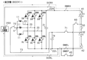
- the power conversion device of the present embodiment is mounted on a vehicle such as an electric vehicle or a hybrid vehicle to form an in-vehicle system.
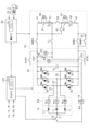
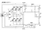
- the power conversion device includes a motor 10, an inverter 20, a high-potential side path 22H, and a low-potential side path 22L.
- the motor 10 is a three-phase synchronous machine, and includes star-connected armature windings 11 of U, V, and W phases, and a rotor (not shown).
- the armature windings 11 of each phase are arranged with an electrical angle of 120°.
- the motor 10 is, for example, a permanent magnet synchronous machine.
- the rotor is capable of transmitting power to the drive wheels of the vehicle. Therefore, the motor 10 serves as a source of torque for driving the vehicle.
- the inverter 20 has three phases of series connections of upper arm switches SWH and lower arm switches SWL.
- An upper arm diode DH which is a freewheel diode, is connected in inverse parallel to the upper arm switch SWH, and a lower arm diode DL, which is also a freewheel diode, is connected in inverse parallel to the lower arm switch SWL.
- each switch SWH, SWL is an IGBT.
- the inverter 20 includes a smoothing capacitor 21.
- a long high-potential side path 22H is connected to the high-potential side terminal of the smoothing capacitor 21.
- a long low-potential side path 22L is connected to the low-potential side terminal of the smoothing capacitor 21.
- the high-potential side path 22H and the low-potential side path 22L are, for example, electrical paths such as bus bars.
- the smoothing capacitor 21 may be provided outside the inverter 20.
- a first end of the armature winding 11 is connected to the connection point between the emitter, which is the low potential terminal of the upper arm switch SWH, and the collector, which is the high potential terminal of the lower arm switch SWL, via a conductive member 23 such as a bus bar.
- the second ends of the armature windings 11 of each phase are connected to each other at the neutral point O.
- the armature windings 11 of each phase are set to have the same number of turns. As a result, the armature windings 11 of each phase are set to have the same inductance, for example.
- a high-potential side path 22H is connected to the collector of the upper arm switch SWH of each phase.
- a low-potential side path 22L is connected to the emitter of the lower arm switch SWL of each phase.
- the system includes a first storage battery 31 (corresponding to the "first storage unit") and a second storage battery 32 (corresponding to the "second storage unit”).
- Each storage battery 31, 32 is a power supply source for rotating and driving the rotor of the motor 10.
- Each storage battery 31, 32 is a battery pack including a series connection of multiple unit batteries.
- the unit battery is a single battery cell that is a single cell, or a series connection of multiple battery cells.
- the full charge capacity (specifically, for example, rated full charge capacity) [Ah] of each unit battery constituting the first storage battery 31 and the second storage battery 32 is the same.
- the positive terminal of the first storage battery 31 is connected to the high potential side path 22H via the first fuse 41, and the negative terminal of the second storage battery 32 is connected to the low potential side path 22L via the second fuse 42.
- the terminal voltages (e.g., rated voltages) of each battery cell constituting the battery pack are set to be the same, for example.
- the battery cells are secondary batteries such as lithium ion batteries.
- the terminal voltage (e.g., rated voltage) of the first storage battery 31 is higher than the terminal voltage (e.g., rated voltage) of the second storage battery 32.
- This configuration can be achieved, for example, by making the number of unit batteries constituting the first storage battery 31 greater than the number of unit batteries constituting the second storage battery 32.
- the power conversion device is provided with a main switch for electrically connecting or disconnecting the first and second storage batteries 31, 32 and the inverter 20.
- the main switches include a high-side main switch SMRH, a low-side main switch SMRL, and a pre-charge main switch SMRP.
- each of the main switches SMRH, SMRL, and SMRP is a mechanical relay. When turned off, each of the main switches SMRH, SMRL, and SMRP blocks the flow of current in both directions, and when turned on, allows the flow of current in both directions.
- the high-side main switch SMRH is provided in the high-side path 22H
- the low-side main switch SMRL is provided in the low-side path 22L.
- a series connection of the pre-charge main switch SMRP and the pre-charge resistor 40 is connected in parallel to the low-side main switch SMRL.
- each of the main switches SMRH, SMRL, and SMRP is not limited to being a mechanical relay, and may be, for example, a semiconductor switching element.
- Each storage battery 31, 32 can be charged by an external charger provided outside the vehicle through external charging control.
- the external charger is, for example, a stationary charger.
- Each storage battery 31, 32 can supply power to a power supply target outside the vehicle through external power supply control.
- external power supply control is also called V2G (Vehicle to Grid).
- V2H Vehicle to Home
- the power conversion device includes a high-potential side connection switch DCRH and a low-potential side connection switch DCRL for electrically connecting or disconnecting between an external charger or a power supply target and the first and second storage batteries 31, 32.
- each connection switch DCRH, DCRL is a mechanical relay. When turned off, each connection switch DCRH, DCRL blocks the flow of current in both directions, and when turned on, allows the flow of current in both directions.
- the high-potential side connection switch DCRH is provided in a portion of the high-potential side path 22H that is closer to the inverter 20 than the high-potential side main switch SMRH.
- the low-potential side connection switch DCRL is provided in a portion of the low-potential side path 22L that is closer to the inverter 20 than the low-potential side main switch SMRL.
- each connection switch DCRH, DCRL is not limited to a mechanical relay, and may be, for example, a semiconductor switching element.
- the power conversion device includes an inter-battery switch 50 (corresponding to an "inter-energy storage unit switch"), a bypass switch 60, a first motor side switch 71, a second motor side switch 72, and a connection path 73 as components for switching the connection state of the first storage battery 31 and the second storage battery 32.
- the inter-battery switch 50, the bypass switch 60, and each of the motor side switches 71, 72 are mechanical relays.
- the inter-battery switch 50, the bypass switch 60, and each of the motor side switches 71, 72 are turned off, they block the flow of current in both directions, and when they are turned on, they allow the flow of current in both directions.
- the inter-battery switch 50, the bypass switch 60, and each of the motor side switches 71, 72 are not limited to mechanical relays, and may be, for example, semiconductor switching elements.
- the inter-battery switch 50 connects the negative terminal of the first storage battery 31 and the positive terminal of the second storage battery 32.
- the inter-battery switch 50 When the inter-battery switch 50 is turned on, the negative terminal of the first storage battery 31 and the positive terminal of the second storage battery 32 are electrically connected. On the other hand, when the inter-battery switch 50 is turned off, the negative terminal of the first storage battery 31 and the positive terminal of the second storage battery 32 are electrically disconnected.
- the bypass switch 60 connects the negative terminal of the first storage battery 31 to the low potential side path 22L.
- the bypass switch 60 When the bypass switch 60 is turned on, the negative terminal of the first storage battery 31 and the negative terminal of the second storage battery 32 are electrically connected.
- the bypass switch 60 when the bypass switch 60 is turned off, the negative terminal of the first storage battery 31 and the negative terminal of the second storage battery 32 are electrically disconnected.
- the first storage battery 31 and the second storage battery 32 constitute the battery unit 30.
- connection path 73 is an electrical path that connects the positive terminal of the second storage battery 32 to the neutral point O.
- a first motor side switch 71 and a second motor side switch 72 are provided on the connection path 73 in this order from the second storage battery 32.
- the power conversion device includes a neutral point capacitor 74, which is a capacitor that connects the connection path 73 and the low potential side path 22L.
- a first end of the neutral point capacitor 74 is connected to a portion of the connection path 73 between the first motor side switch 71 and the second motor side switch 72.
- a second end of the neutral point capacitor 74 is connected to a portion of the low potential side path 22L that is closer to the inverter 20 than the low potential side main switch SMRL and the precharge main switch SMRP.
- the first motor side switch 71 When the first motor side switch 71 is turned on, the first end of the neutral point capacitor 74 is electrically connected to the positive terminal of the second storage battery 32. On the other hand, when the first motor side switch 71 is turned off, the first end of the neutral point capacitor 74 is electrically disconnected from the positive terminal of the second storage battery 32.
- the second motor side switch 72 When the second motor side switch 72 is turned on, the neutral point O of the armature winding 11 is electrically connected to the first end of the neutral point capacitor 74. On the other hand, when the second motor side switch 72 is turned off, the neutral point O is electrically disconnected from the first end of the neutral point capacitor 74.
- the power conversion device is equipped with a first current sensor 81, a second current sensor 82, a phase current sensor 83, and a motor current sensor 84 as current sensors that detect the current flowing in each part of the power conversion device.
- the first current sensor 81 detects the current flowing in the first storage battery 31, and the second current sensor 82 detects the current flowing in the second storage battery 32.
- the phase current sensor 83 detects the current flowing in the armature winding 11 of each phase.
- the motor current sensor 84 detects the current flowing in the connection path 73, and in this embodiment, detects the current flowing in the part of the connection path 73 that is closer to the neutral point O than the connection point with the neutral point capacitor 74.
- the power conversion device includes a capacitor voltage sensor 85 that detects the terminal voltage of the neutral point capacitor 74, a first voltage sensor 86 that detects the terminal voltage of the first storage battery 31, and a second voltage sensor 87 that detects the terminal voltage of the second storage battery 32.
- the first voltage sensor 86 detects, for example, the terminal voltage of each unit battery that constitutes the first storage battery 31, and the second voltage sensor 87 detects, for example, the terminal voltage of each unit battery that constitutes the second storage battery 32.
- the power conversion device also includes a power supply voltage sensor 89 that detects the terminal voltage of the smoothing capacitor 21.
- the power conversion device is equipped with a temperature sensor 88 that detects the temperatures of the first storage battery 31 and the second storage battery 32.
- the temperature sensor 88 detects, for example, the temperature of each unit battery that constitutes the first storage battery 31 and the temperature of each unit battery that constitutes the second storage battery 32.
- the power conversion device also includes, as another sensor, a rotation angle sensor (not shown) that detects the rotation angle (electrical angle) of the rotor.
- the system includes a battery ECU 90 that controls the battery unit 30, and an EVECU 100 that controls the inverter 20.
- the battery ECU 90 is an electronic control unit that is primarily comprised of a microcomputer 91.
- the EVECU 100 is an electronic control unit that is primarily comprised of a microcomputer 101.
- the battery ECU 90 and the EVECU 100 are capable of exchanging information via a communication section such as CAN communication.
- Each microcomputer 91, 101 has a CPU (Central Processing Unit).
- the functions provided by each microcomputer 91, 101 can be provided by software recorded in a physical memory device and a computer that executes the software, by software alone, by hardware alone, or by a combination of these.
- each microcomputer 91, 101 when each microcomputer 91, 101 is provided by an electronic circuit that is hardware, it can be provided by a digital circuit including a large number of logic circuits, or an analog circuit.
- each microcomputer 91, 101 executes a program stored in a non-transitory tangible storage medium that serves as a storage unit provided in the microcomputer.
- the program includes, for example, a program for the process shown in FIG. 5, which will be described later.
- a method corresponding to the program is executed by executing a set of instructions that constitute the program.
- the storage unit is, for example, a non-volatile memory.
- the program stored in the storage unit can be updated via a communication network such as the Internet, for example, OTA (Over The Air).
- the battery ECU 90 receives detection values from the first current sensor 81, the second current sensor 82, the first voltage sensor 86, the second voltage sensor 87, and the temperature sensor 88.
- the battery ECU 90 calculates the SOC of each unit battery that constitutes the first storage battery 31 based on the detection values from the first voltage sensor 86, the first current sensor 81, and the temperature sensor 88.
- the battery ECU 90 calculates the SOC of each unit battery that constitutes the second storage battery 32 based on the detection values from the second voltage sensor 87, the second current sensor 82, and the temperature sensor 88.
- the detection values of the phase current sensor 83, motor current sensor 84, capacitor voltage sensor 85, power supply voltage sensor 89, and rotation angle sensor are input to the EVECU 100. Based on the detection values of each sensor input, the EVECU 100 performs switching control of each switch SWH, SWL that constitutes the inverter 20 to feedback control the control amount of the motor 10 to a command value.
- the control amount is, for example, torque.
- the upper arm switch SWH and the lower arm switch SWL are alternately turned on. As a result, the rotational power of the rotor of the motor 10 is transmitted to the drive wheels, causing the vehicle to run.
- the main switches SMRH, SMRL, SMRP, the connection switches DCRH, DCRL, the inter-battery switch 50, the bypass switch 60, and the motor-side switches 71, 72 may be controlled by either the battery ECU 90 or the EVECU 100.
- the main switches SMRH, SMRL, SMRP, the connection switches DCRH, DCRL, the inter-battery switch 50, the bypass switch 60, the first motor-side switch 71, and the second motor-side switch 72 are controlled by the EVECU 100.
- the external charger is a high-voltage charger 200 or a low-voltage charger 210, as shown in FIG. 2 and FIG. 3.
- the charging voltage of the high-voltage charger 200 is higher than the terminal voltage (specifically, the rated voltage) of the series connection of the first and second storage batteries 31 and 32, for example, 800 V.
- the charging voltage of the low-voltage charger 210 is lower than the terminal voltage of the series connection of the first and second storage batteries 31 and 32, and is higher than the terminal voltage (specifically, the rated voltage) of the first storage battery 31, for example, 400 V.
- the high-potential side connection switch DCRH and the low-potential side connection switch DCRL are switched on.
- the high-potential side connection switch DCRH and the low-potential side connection switch DCRL are switched off.
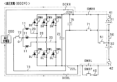
- FIG. 2 shows the control state of each switch during external charging control using the high-voltage charger 200.
- the charging plug of the high-voltage charger 200 is electrically connected to each connection switch DCRH, DCRL by the vehicle user, thereby electrically connecting the high-voltage charger 200 and the power conversion device.
- the EVECU 100 determines that the external charger connected to the power conversion device is the high-voltage charger 200, it turns off the pre-charge main switch SMRP, the bypass switch 60, the first motor side switch 71, the second motor side switch 72, and the upper and lower arm switches SWH, SWL of all phases of the inverter 20, and turns on the high potential side main switch SMRH, the low potential side main switch SMRL, and the inter-battery switch 50.
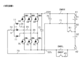
- FIG. 3 shows the control state of each switch during external charging control using the low-voltage charger 210.
- the low-voltage charger 210 and the power conversion device are electrically connected when the charging plug of the low-voltage charger 210 is electrically connected to each connection switch DCRH, DCRL by the vehicle user.
- the EVECU 100 determines that the external charger connected to the power conversion device is the low-voltage charger 210, it turns off the pre-charge main switch SMRP and the inter-battery switch 50, and turns on the high-potential side main switch SMRH, the low-potential side main switch SMRL, the bypass switch 60, the first motor side switch 71, and the second motor side switch 72.
- a current flows through a closed circuit including the low-voltage charger 210, the high-potential side path 22H, the first storage battery 31, the bypass switch 60, and the low-potential side path 22L, and the first storage battery 31 is charged.
- the EVECU 100 performs switching control to alternately turn on the upper and lower arm switches SWH, SWL of at least one phase, or performs switching control of the upper arm switch SWH of at least one phase with the lower arm switches SWL of all phases of the inverter 20 turned off, thereby stepping down the output voltage of the low-voltage charger 210 and supplying it to the second storage battery 32.
- the EVECU 100 performs step-down control, which is the above-mentioned switching control for controlling the voltage detected by the capacitor voltage sensor 85 (hereinafter, neutral point capacitor voltage VN) to the target charging voltage.
- a current flows through a closed circuit including the low-voltage charger 210, the high potential side path 22H, the upper arm switch SWH of the inverter 20, the armature winding 11, the neutral point O, the second motor side switch 72, the first motor side switch 71, the second storage battery 32, and the low potential side path 22L, and the second storage battery 32 is charged. Because the terminal voltage of the second storage battery 32 is lower than the terminal voltage of the first storage battery 31, the target charging voltage of the second storage battery 32 is lower than the target charging voltage of the first storage battery 31.
- the first storage battery 31 corresponds to the "source storage unit”
- the second storage battery 32 corresponds to the "destination storage unit.”
- the armature winding 11, the inverter 20, and the connection path 73 correspond to the "transformer circuit.”
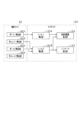
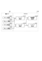
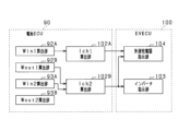
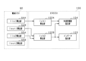
- FIG. 4 is a functional block diagram of the battery ECU 90 and the EVECU 100.
- the battery ECU 90 includes a first input power calculation unit 92A, a first output power calculation unit 92B, a second input power calculation unit 93A, and a second output power calculation unit 93B as processing units that calculate parameters related to charging and discharging the first storage battery 31 and the second storage battery 32.
- the first input power calculation unit 92A calculates the first upper limit input power Win1 based on the battery state of the first storage battery 31.
- the first upper limit input power Win1 is the maximum value of power that can be input to the first storage battery 31.
- the battery state of the first storage battery 31 includes, for example, the temperature of the first storage battery 31 detected by the temperature sensor 88 and the SOC of the first storage battery 31.
- the first input power calculation unit 92A calculates a smaller first upper limit input power Win1 the higher the SOC of the first storage battery 31 or the lower the temperature of the first storage battery 31.
- the SOC used in calculating the first upper limit input power Win1 may be, for example, the maximum value of the SOC of each unit battery constituting the first storage battery 31 or the average value of the SOC of each unit battery.
- the first output power calculation unit 92B calculates the first upper limit output power Wout1 based on the battery state of the first storage battery 31.
- the first upper limit output power Wout1 is the maximum value of power that can be output from the first storage battery 31.
- the first output power calculation unit 92B calculates a larger first upper limit output power Wout1 the higher the SOC of the first storage battery 31 or the higher the temperature of the first storage battery 31 detected by the temperature sensor 88.
- the SOC used to calculate the first upper limit output power Wout1 may be, for example, the minimum value of the SOC of each unit battery that constitutes the first storage battery 31, or the average value of the SOC of each unit battery.
- the second input power calculation unit 93A calculates the second upper limit input power Win2 based on the battery state of the second storage battery 32.
- the second upper limit input power Win2 is the maximum value of power that can be input to the second storage battery 32.
- the battery state of the second storage battery 32 includes, for example, the temperature of the second storage battery 32 detected by the temperature sensor 88 and the SOC of the second storage battery 32.
- the second input power calculation unit 93A calculates a smaller second upper limit input power Win2 the higher the SOC of the second storage battery 32 or the lower the temperature of the second storage battery 32.
- the SOC used in calculating the second upper limit input power Win2 may be, for example, the maximum value of the SOC of each unit battery constituting the second storage battery 32, or the average value of the SOC of each unit battery.
- the second output power calculation unit 93B calculates the second upper limit output power Wout2 based on the battery state of the second storage battery 32.
- the second upper limit output power Wout2 is the maximum value of power that can be output from the second storage battery 32. For example, the higher the SOC of the second storage battery 32 or the higher the temperature of the second storage battery 32 detected by the temperature sensor 88, the larger the second output power calculation unit 93B calculates the second upper limit output power Wout2 to be.
- the SOC used to calculate the second upper limit output power Wout2 may be, for example, the minimum value of the SOC of each unit battery that constitutes the second storage battery 32, or the average value of the SOC of each unit battery.
- the EVECU 100 includes a first charging current calculation unit 102A, a second charging current calculation unit 102B, an inverter instruction unit 103, and an external charger instruction unit 104.
- the first charging current calculation unit 102A calculates the first command charging current Ich1, which is a command value for the charging current of the first storage battery 31, based on the calculated first upper limit input power Win1 and the first detected voltage VH, which is the detected voltage of the first voltage sensor 86.
- the second charging current calculation unit 102B calculates the second command charging current Ich2, which is a command value for the charging current of the second storage battery 32, based on the calculated second upper limit input power Win2, the second detection voltage VL, which is the detection voltage of the second voltage sensor 87, and the calculated first upper limit output power Wout1.
- the second command charging current Ich2 corresponds to the "destination command charging current.”
- the reason why the first upper limit output power Wout1 of the first storage battery 31 is used to calculate the charging current of the second storage battery 32 is to prevent the output power of the first storage battery 31 from exceeding the first upper limit output power Wout1 even when the external charging control is suddenly stopped, and to prevent over-discharge of the first storage battery 31 from occurring.
- the second charging current calculation unit 102B first selects the second upper limit input power Win2 (corresponding to the "input upper limit”) or the first upper limit output power Wout1 (corresponding to the "output upper limit”), whichever has the smaller absolute value, as the reference power Wstd.
- the inverter instruction unit 103 performs step-down control of the inverter 20 to control the current flowing through the second storage battery 32 to the calculated second command charging current Ich2. Specifically, for example, the inverter instruction unit 103 performs step-down control of the inverter 20 to control the motor current IN, which is the current detected by the second current sensor 82 or the current detected by the motor current sensor 84, to the second command charging current Ich2.
- the external charger instruction unit 104 calculates the external command charging current Icht, which is the command value of the charging current output from the low-voltage charger 210, based on the calculated first and second command charging currents Ich1 and Ich2 and the first and second detection voltages VH and VL.
- the first and second detection voltages VH and VL are used to take into account the voltage drop caused by the step-down control.
- the external charger instruction unit 104 calculates the external command charging current Icht (e.g., 62.5 A) by adding the first command charging current Ich1 (e.g., 50 A) to the calculated first command conversion current Ichc1 (e.g., 12.5 A).
- the external charger instruction unit 104 transmits the calculated external command charging current Icht to the low-voltage charger 210.
- the low-voltage charger 210 is controlled so that the output current of the low-voltage charger 210 becomes the external command charging current Icht.
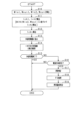
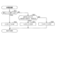
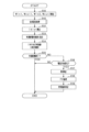
- FIG. 5 is a flowchart showing the procedure for the external charging control process of the low-voltage charger 210. This process is executed repeatedly, for example at a predetermined control period, by cooperation between the EVECU 100 and the battery ECU 90.
- step S10 the battery ECU 90 calculates the first upper limit input power Win1, the first upper limit output power Wout1, the second upper limit input power Win2, and the second upper limit output power Wout2, and transmits them to the EVECU 100.
- step S11 the EVECU 100 calculates the first command charging current Ich1 and the second command charging current Ich2.
- the process of step S11 corresponds to the "command value calculation unit.”
- the EVECU 100 calculates the external command charging current Icht in step S12, and transmits the external command charging current Icht to the low-voltage charger 210 in step S13.
- the process of step S12 corresponds to the "external command value calculation unit.”
- step S14 the EVECU 100 performs step-down control of the inverter 20 to control the current flowing through the second storage battery 32 to the second command charging current Ich2.
- the process of step S14 corresponds to the "circuit control unit.”
- step S15 the EVECU 100 determines whether the external charging control has ended. If the EVECU 100 determines that the external charging control has not ended, in step S16, the EVECU 100 determines whether the direction of the current flowing to the first storage battery 31 is the direction to charge the first storage battery 31.
- This determination process is a process for determining whether the external charging control has been suddenly stopped. If the external charging control is suddenly stopped, the direction of the current flowing to the first storage battery 31 switches from the direction to charge the first storage battery 31 to the direction to discharge the first storage battery 31.
- the EVECU 100 may determine the direction of the current flowing to the first storage battery 31 based on the current detected by the first current sensor 81, for example.
- the EVECU 100 determines that the direction of the current flowing through the first storage battery 31 is the direction in which the first storage battery 31 is charged, the EVECU 100 continues the external charging control. On the other hand, if the EVECU 100 determines that the direction of the current flowing through the first storage battery 31 is the direction in which the first storage battery 31 is discharged, the EVECU 100 determines in step S17 that an abnormality has occurred that causes the external charging control to suddenly stop.
- step S18 the EVECU 100 performs fail-safe processing.
- the EVECU 100 stops the step-down control (switching control) of the inverter 20, and after the current flowing through the high-potential side main switch SMRH and the low-potential side main switch SMRL becomes zero, it performs processing to switch off each of the main switches SMRH, SMRL. This makes it possible to suppress the occurrence of welding of each of the main switches SMRH, SMRL.
- step S19 the EVECU 100 identifies that a fault has occurred in any of the components of the power conversion device, such as each of the connection switches DCRH, DCRL, or from each of the connection switches DCRH, DCRL to the charging plug.
- This identification information is stored in the memory of the EVECU 100.
- steps S16 to S19 correspond to the "abnormality processing unit.”
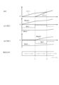
- Figure 6 shows an example of each waveform when external charging control of the low-voltage charger 210 is executed.
- SOC1 is the SOC of the unit battery that constitutes the first storage battery
- SOC2 is the SOC of the unit battery that constitutes the second storage battery 32.
- Wr1 is the actual charge/discharge power of the first storage battery
- Wr2 is the actual charge/discharge power of the second storage battery 32.
- the sign of each power is positive on the discharge side and negative on the charge side.
- the first command charging current Ich1 is calculated based on the first upper limit input power Win1 and the first detected voltage VH, and the charging current of the first storage battery 31 is controlled to the first command charging current Ich1.
- the SOC1 gradually increases, and the terminal-to-terminal voltage of the first storage battery 31 gradually increases.
- the magnitude of the first upper limit input power Win1 gradually decreases, and the magnitude of the first upper limit output power Wout1 gradually increases.
- the second command charging current Ich2 is calculated based on the second upper limit input power Win2, the second detection voltage VL, and the first upper limit output power Wout1.
- the SOC2 gradually increases, and the terminal voltage of the second storage battery 32 gradually increases.
- the magnitude of the second upper limit input power Win2 gradually decreases, and the magnitude of the second upper limit output power Wout2 gradually increases.
- the second command charging current Ich2 of the second storage battery 32 is calculated based on the smaller absolute value of the second upper limit input power Win2 and the first upper limit output power Wout1.
- the discharge current of the first storage battery 31 does not become excessively large due to charging of the second storage battery 32, and it is possible to prevent the discharge power Wr1 of the first storage battery 31 from exceeding the first upper limit output power Wout1. This makes it possible to prevent the occurrence of a malfunction of the first storage battery 31.
- the step-down control of the inverter 20 is stopped at time t2, and the high-side main switch SMRH and the low-side main switch SMRL are switched off at time t3.
- the discharge power Wr1 of the first storage battery 31 does not exceed the first upper limit output power Wout1 during the period from when the external charging control is suddenly stopped until the step-down control of the inverter 20 is stopped.
- FIG. 7 shows an example of each waveform when external charging control according to the comparative example is executed.
- the first upper limit output power Wout1 is not used to calculate the second command charging current Ich2.
- the second command charging current Ich2 is calculated as "Win2/VL". In this case, if the external charging control suddenly stops at time t1, the discharge power Wr1 of the first storage battery 31 will greatly exceed the first upper limit output power Wout1, and a failure of the first storage battery 31 may occur.
- the EVECU 100 may stop the step-down control of the inverter 20. This makes it possible to quickly stop discharging the first storage battery 31.
- the second command charging current Ich2 may be calculated as a value smaller than "Wstd/VL”. Also, the first command charging current Ich1 may be calculated as a value smaller than "Win1/VH”.
- the distribution ratio of the output current of the low-voltage charger 210 to the first and second storage batteries 31, 32 is adjusted based on the first upper limit output power Wout1 of the first storage battery 31, the second upper limit input power Win2 of the second storage battery 32, and the SOCs of the first and second storage batteries 31, 32.
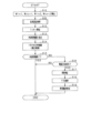
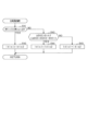
- FIG. 8 is a flowchart showing the procedure for the external charging control process of the low-voltage charger 210. This process is executed repeatedly, for example at a predetermined control period, by cooperation between the EVECU 100 and the battery ECU 90.
- step S20 the EVECU 100 performs a ratio setting process.
- FIG. 9 is a flowchart showing the procedure for the ratio setting process.
- the process of step S20 corresponds to the "command value calculation unit.”
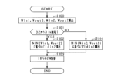
- step S21 the EVECU 100 determines whether the absolute value of the first upper limit output power Wout1 is smaller than the absolute value of the second upper limit input power Win2.
- step S22 the EVECU 100 imposes the condition that the charging power of the first storage battery 31 is equal to or less than the first upper limit input power Win1 and the charging power of the second storage battery 32 is equal to or less than the second upper limit input power Win2, and calculates the first command charging current Ich1 to be greater than the second command charging current Ich2.
- the charging power of the first storage battery 31 becomes greater than the charging power of the second storage battery 32.
- the first command charging current Ich1 corresponds to the "supply source command charging current".
- step S22 a process of step S22 is provided in which charging of the first storage battery 31 is prioritized over the second storage battery 32.
- the EVECU 100 calculates the first command charging current Ich1 based on the first upper limit input power Win1 and the first detected voltage VH, and specifically, for example, the first command charging current Ich1 may be set to "Win1/VH".
- the EVECU 100 sets the second command charging current Ich2 to 0.
- the EVECU 100 determines that the absolute value of the first upper limit output power Wout1 is equal to or greater than the absolute value of the second upper limit input power Win2, then in step S23, it calculates the difference in charging rates ⁇ SOC and determines whether the calculated difference in charging rates ⁇ SOC is greater than the determination threshold value Sth.
- the difference in charging rates ⁇ SOC is the value obtained by subtracting the SOC2 of the unit battery constituting the second storage battery 32 from the SOC1 of the unit battery constituting the first storage battery 31.
- step S24 EVECU 100 imposes the condition that the charging power of the first storage battery 31 is equal to or less than the first upper limit input power Win1 and the charging power of the second storage battery 32 is equal to or less than the second upper limit input power Win2, and calculates the second command charging current Ich2 to be greater than the first command charging current Ich1. As a result, the charging power of the second storage battery 32 becomes greater than the charging power of the first storage battery 31.
- the processing of step S24 is intended to reduce the difference between the SOC of each unit battery constituting the first storage battery 31 and the SOC of each unit battery constituting the second storage battery 32 as quickly as possible.
- the EVECU 100 calculates the second command charging current Ich2 based on the second upper limit input power Win2 and the second detection voltage VL. Specifically, for example, the second command charging current Ich2 may be set to "Win2/VL".
- step S25 the EVECU 100 sets the first command charging current Ich1 and the second command charging current Ich2 to the same value by imposing the condition that the charging power of the first storage battery 31 is equal to or less than the first upper limit input power Win1 and the charging power of the second storage battery 32 is equal to or less than the second upper limit input power Win2. This prevents the difference between the SOC of each unit battery constituting the first storage battery 31 and the SOC of each unit battery constituting the second storage battery 32 from becoming too large.
- step S12 the EVECU 100 calculates the external command charging current Icht by adding the first command charging current Ich1 and the second command charging current Ich2 calculated in the processing of FIG. 9.
- step S13 the EVECU 100 transmits the external command charging current Icht to the low-voltage charger 210.
- step S14 the second command charging current Ich2 calculated in the processing of FIG. 9 is used for step-down control of the inverter 20.
- Figure 10 shows an example of each waveform when external charging control of the low-voltage charger 210 is executed.
- the EVECU 100 determines that the absolute value of the first upper limit output power Wout1 is smaller than the absolute value of the second upper limit input power Win2. As a result, the EVECU 100 calculates the first command charging current Ich1 to be larger than the second command charging current Ich2. At time t1, the EVECU 100 determines that the absolute value of the first upper limit output power Wout1 is equal to or greater than the absolute value of the second upper limit input power Win2. The EVECU 100 then determines that the difference in charging rates ⁇ SOC is greater than the determination threshold Sth. As a result, the EVECU 100 calculates the second command charging current Ich2 to be greater than the first command charging current Ich1.
- the EVECU 100 determines that the difference in charging rate ⁇ SOC is equal to or less than the determination threshold value Sth. As a result, the EVECU 100 sets the first command charging current Ich1 and the second command charging current Ich2 to the same value.
- the second command charging current Ich2 may be set to a value greater than zero.
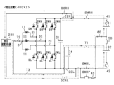
- the EVECU 100 determines that the power supply target connected to the power conversion device is the high-voltage power supply target 220, it turns off the pre-charge main switch SMRP, the bypass switch 60, the first motor side switch 71, the second motor side switch 72, and the upper and lower arm switches SWH, SWL of all phases of the inverter 20, and turns on the connection switches DCRH, DCRL, the high-potential side main switch SMRH, the low-potential side main switch SMRL, and the inter-battery switch 50.
- first storage battery 31 and the second storage battery 32 being connected in series to the high-voltage power supply target 220.
- Figure 12 shows the control state of each switch during external power supply control in which power is supplied from the first and second storage batteries 31, 32 to the low-voltage power supply target unit 230.
- the rated voltage of the low-voltage power supply target unit 230 is lower than the rated voltage of the high-voltage power supply target unit 220.
- the EVECU 100 determines that the power supply target unit connected to the power conversion device is the low-voltage power supply target unit 230, it turns off the pre-charge main switch SMRP and the inter-battery switch 50, and turns on each connection switch DCRH, DCRL, the high-potential side main switch SMRH, the low-potential side main switch SMRL, the bypass switch 60, the first motor side switch 71, and the second motor side switch 72.
- the EVECU 100 performs switching control to alternately turn on the upper and lower arm switches SWH, SWL of at least one phase, or performs switching control of the lower arm switch SWL of at least one phase with the upper arm switches SWH of all phases of the inverter 20 turned off, thereby boosting the output voltage of the second storage battery 32 and supplying it to the low-voltage power supply target portion 230.
- the EVECU 100 performs boost control, which is the switching control described above for controlling the power supply voltage VB, which is the detection voltage of the power supply voltage sensor 89, to the target power supply voltage.
- a current flows through a closed circuit including the second storage battery 32, the connection path 73, the armature winding 11, the inverter 20, the high-potential side path 22H, the low-voltage power supply target portion 230, and the low-potential side path 22L, and power is supplied from the second storage battery 32 to the low-voltage power supply target portion 230.
- the second storage battery 32 corresponds to the "source storage unit” and the first storage battery 31 corresponds to the "destination storage unit.”
- the external power supply control may suddenly stop due to some factor.
- current continues to be output from the second storage battery 32 to the first storage battery 31 via the inverter 20 until the switching control of the inverter 20 stops.
- overcharging of the first storage battery 31 may occur, causing the first storage battery 31 to break down. Therefore, in this embodiment, the discharge current of the second storage battery 32 is set so that overcharging of the first storage battery 31 does not occur.
- the setting method will be described below.
- Figure 13 is a functional block diagram of the battery ECU 90 and the EVECU 100.
- the EVECU 100 includes a first discharge current calculation unit 105A and a second discharge current calculation unit 105B.
- the first discharge current calculation unit 105A calculates a first command discharge current Idis1, which is a command value for the discharge current of the first storage battery 31, based on the first upper limit output power Wout1 and the first detection voltage VH.
- the second discharge current calculation unit 105B calculates the second command discharge current Idis2, which is a command value for the discharge current of the second storage battery 32, based on the first upper limit input power Win1 in addition to the second upper limit output power Wout2 and the second detection voltage VL.
- the second command discharge current Idis2 corresponds to the "supply source command discharge current.”
- the reason why the first upper limit input power Win1 of the first storage battery 31 is used to calculate the discharge current of the second storage battery 32 is to prevent the input power of the first storage battery 31 from exceeding the first upper limit input power Win1 even when the external power supply control is suddenly stopped, and to prevent overcharging of the first storage battery 31 from occurring.
- the second discharge current calculation unit 105B first selects the second upper limit output power Wout2 (corresponding to the "output upper limit value”) or the first upper limit input power Win1 (corresponding to the "input upper limit value”), whichever has the smaller absolute value, as the reference power Wstd.
- the inverter instruction unit 103 performs boost control of the inverter 20 to control the current flowing through the second storage battery 32 (e.g., the current detected by the second current sensor 81B or the motor current IN) to the calculated second command discharge current Idis2.
- the external power supply instruction unit 104D calculates the external command discharge current Idist, which is the command value of the discharge current to be supplied from each storage battery 31, 32 to the low-voltage power supply target unit 230, based on the calculated first and second command discharge currents Idis1, Idis2 and the first and second detection voltages VH, VL.
- the first and second detection voltages VH, VL are used to take into account the voltage increase due to the boost control.
- FIG. 14 is a flowchart showing the procedure for the external power supply control process for the low-voltage power supply target unit 230. This process is executed repeatedly, for example, at a predetermined control period, by cooperation between the EVECU 100 and the battery ECU 90.
- step S30 the battery ECU 90 calculates the first upper limit input power Win1, the first upper limit output power Wout1, the second upper limit input power Win2, and the second upper limit output power Wout2, and transmits them to the EVECU 100.
- step S31 the EVECU 100 calculates the first command discharge current Idis1 and the second command discharge current Idis2.
- the process of step S31 corresponds to the "command value calculation unit.”
- the EVECU 100 calculates the external command discharge current Idist in step S32, and transmits the external command discharge current Idist to the low-voltage power supply target unit 230 in step S33.
- the process of step S32 corresponds to the "external command value calculation unit.”
- step S34 the EVECU 100 performs boost control of the inverter 20 to control the current flowing through the second storage battery 32 to the second command discharge current Idis2.
- the process of step S34 corresponds to the "circuit control unit.”
- step S35 the EVECU 100 determines whether the external power supply control has ended. If the EVECU 100 determines that the external power supply control has not ended, in step S36, the EVECU 100 determines whether the direction of the current flowing to the first storage battery 31 is the direction of discharging from the first storage battery 31.
- This determination process is a process for determining whether the external power supply control has been suddenly stopped. If the external power supply control is suddenly stopped, the direction of the current flowing to the first storage battery 31 switches from the direction of discharging from the first storage battery 31 to the direction of charging the first storage battery 31.
- the EVECU 100 may determine the direction of the current flowing to the first storage battery 31 based on the current detected by the first current sensor 81, for example.
- the EVECU 100 determines that the direction of the current flowing through the first storage battery 31 is the direction discharging the first storage battery 31, the EVECU 100 continues the external power supply control. On the other hand, if the EVECU 100 determines that the direction of the current flowing through the first storage battery 31 is the direction charging the first storage battery 31, the EVECU 100 determines in step S37 that an abnormality has occurred that causes the external power supply control to suddenly stop.
- step S38 the EVECU 100 performs fail-safe processing.
- the EVECU 100 performs fail-safe processing by stopping the boost control (switching control) of the inverter 20 and switching off each of the main switches SMRH and SMRL after the current flowing through the high-potential side main switch SMRH and the low-potential side main switch SMRL becomes zero.
- step S39 the EVECU 100 identifies that a failure has occurred in any of the components of the power conversion device, including each of the connection switches DCRH, DCRL, and the components from each of the connection switches DCRH, DCRL to the low-voltage power supply target unit 230.
- This identification information is stored in the memory of the EVECU 100.
- steps S36 to S39 correspond to the "abnormality processing unit.”
- the charging power of the first storage battery 31 can be prevented from exceeding the first upper limit input power Win1, and overcharging of the first storage battery 31 can be prevented.
- the EVECU 100 may stop the boost control of the inverter 20. This makes it possible to quickly stop charging the first storage battery 31.
- the second command discharge current Idis2 may be calculated as a value smaller than "Wstd/VL". Also, the first command discharge current Idis1 may be calculated as a value smaller than "Wout1/VH”.
- the fourth embodiment will be described with reference to the drawings, focusing on differences from the third embodiment.
- the distribution ratio of the currents supplied from the first and second storage batteries 31 and 32 to the low-voltage power supply target unit 230 is adjusted.
- FIG. 15 is a flowchart showing the procedure for the external power supply control process for the low-voltage power supply target unit 230. This process is executed repeatedly, for example, at a predetermined control period, by cooperation between the EVECU 100 and the battery ECU 90.
- step S40 the EVECU 100 performs a ratio setting process.
- FIG. 16 is a flowchart showing the procedure for the ratio setting process.
- the process of step S40 corresponds to the "command value calculation unit.”
- step S41 the EVECU 100 determines whether the absolute value of the first upper limit input power Win1 is smaller than the absolute value of the second upper limit output power Wout2.
- step S42 the EVECU 100 imposes the condition that the discharge power of the first storage battery 31 is equal to or less than the first upper limit output power Wout1 and the discharge power of the second storage battery 32 is equal to or less than the second upper limit output power Wout2, and calculates the first command discharge current Idis1 to be greater than the second command discharge current Idis2.
- the first command discharge current Idis1 corresponds to the "destination command discharge current".
- step S42 a process of step S42 that prioritizes discharging of the first storage battery 31 over the second storage battery 32.
- the EVECU 100 calculates the first command discharge current Idis1 based on the first upper limit output power Wout1 and the first detected voltage VH, and specifically, for example, the first command discharge current Idis1 may be set to "Wout1/VH".
- the EVECU 100 sets the second command discharge current Idis2 to 0.
- the EVECU 100 determines that the absolute value of the first upper limit input power Win1 is equal to or greater than the absolute value of the second upper limit output power Wout2, then in step S43, it calculates the charging rate difference ⁇ SOC and determines whether the calculated charging rate difference ⁇ SOC is greater than the determination threshold value Sth.
- the charging rate difference ⁇ SOC is a value obtained by subtracting the SOC1 of the unit battery constituting the first storage battery 31 from the SOC2 of the unit battery constituting the second storage battery 32.
- step S44 EVECU 100 imposes the condition that the discharge power of the first storage battery 31 is equal to or less than the first upper limit output power Wout1 and the discharge power of the second storage battery 32 is equal to or less than the second upper limit output power Wout2, and calculates the second command discharge current Idis2 to be greater than the first command discharge current Idis1. As a result, the discharge power of the second storage battery 32 becomes greater than the discharge power of the first storage battery 31.
- step S44 is intended to prevent the difference between the SOC of each unit battery constituting the first storage battery 31 and the SOC of each unit battery constituting the second storage battery 32 from becoming large.
- the EVECU 100 calculates the second command discharge current Idis2 based on the second upper limit output power Wout2 and the second detection voltage VL.
- the second command discharge current Idis2 may be set to "Wout2/VL".
- step S45 the EVECU 100 sets the first command discharge current Idis1 and the second command discharge current Idis2 to the same value by imposing the condition that the discharge power of the first storage battery 31 is equal to or less than the first upper limit output power Wout1 and the discharge power of the second storage battery 32 is equal to or less than the second upper limit output power Wout2. This prevents the difference between the SOC of each unit battery constituting the first storage battery 31 and the SOC of each unit battery constituting the second storage battery 32 from becoming too large.
- step S32 the EVECU 100 calculates the external command discharge current Idist by adding the first command discharge current Idis1 and the second command discharge current Idis2 calculated in the processing of FIG. 16.
- step S33 the EVECU 100 transmits the external command discharge current Idist to the low-voltage power supply target unit 230.
- step S34 the second command discharge current Idis2 calculated in the processing of FIG. 16 is used for boost control of the inverter 20.
- the risk of overcharging the first storage battery 31 due to a sudden stop of the external power supply control can be reduced.
- the second command discharge current Idis2 may be set to a value greater than zero.
- the EVECU 100 performs power transmission control (specifically, for example, equalization control) for transmitting power from one of the first storage battery 31 and the second storage battery 32 to the other by performing switching control of the inverter 20.
- power transmission control specifically, for example, equalization control
- FIG. 17 shows the control state of each switch during equalization control.
- each connection switch DCRH and DCRL is controlled to be off.
- the EVECU 100 turns on the high-potential side main switch SMRH, the low-potential side main switch SMRL, the inter-battery switch 50, the first motor side switch 71, and the second motor side switch 72, and turns off the pre-charge main switch SMRP and the bypass switch 60.
- the EVECU 100 also performs switching control for at least one phase of the inverter 20 to transfer power from one of the first storage battery 31 and the second storage battery 32 to the other.
- the EVECU 100 performs a first control to supply current from the first storage battery 31 to the second storage battery 32 via the inverter 20, the armature winding 11, and the connection path 73 by performing a step-down control for at least one phase.
- the EVECU 100 also performs a second control to supply current to the first storage battery 31 via the second storage battery 32, the connection path 73, the armature winding 11, and the inverter 20 by performing a step-up control for at least one phase.
- the equalization control for example, it is possible to make the SOC of each unit battery that constitutes the first storage battery 31 equal to the SOC of each unit battery that constitutes the second storage battery 32.
- FIG. 18 is a flowchart showing the steps of the equalization control process. This process is executed repeatedly, for example at a predetermined control period, by the cooperation of the EVECU 100 and the battery ECU 90.
- step S50 the battery ECU 90 calculates the first upper limit input power Win1, the first upper limit output power Wout1, the second upper limit input power Win2, and the second upper limit output power Wout2, and transmits them to the EVECU 100.
- step S51 the EVECU 100 determines whether a first control is being executed in which the first storage battery 31, which is the "source storage unit,” supplies power to the second storage battery 32, which is the “destination storage unit,” or a second control is being executed in which the second storage battery 32, which is the “source storage unit,” supplies power to the first storage battery 31, which is the "destination storage unit.”
- EVECU 100 determines that the first control is being executed, it proceeds to step S52.
- step S52 EVECU 100 calculates the first command discharge current Idis1 based on the second upper limit input power Win2, the first upper limit output power Wout1, and the first detection voltage VH.
- EVECU 100 first selects the second upper limit input power Win2 (corresponding to the "input upper limit value") or the first upper limit output power Wout1 (corresponding to the "output upper limit value”), whichever has the smaller absolute value, as the first standard power Wstd1.
- step S53 the EVECU 100 performs step-down control of the inverter 20 to control the current flowing through the first storage battery 31 (e.g., the current detected by the first current sensor 81) to the calculated first command discharge current Idis1.
- This allows power to be supplied from the first storage battery 31 to the second storage battery 32 while preventing the discharge power of the first storage battery 31 from exceeding the first upper limit output power Wout1, thereby preventing over-discharge of the first storage battery 31.
- step S54 EVECU 100 calculates the second command discharge current Idis2 based on the first upper limit input power Win1, the second upper limit output power Wout2, and the second detection voltage VL.
- EVECU 100 first selects the first upper limit input power Win1 (corresponding to the "input upper limit value") or the second upper limit output power Wout2 (corresponding to the "output upper limit value”), whichever has the smaller absolute value, as the second standard power Wstd2.
- step S53 the EVECU 100 performs step-down control of the inverter 20 to control the current flowing through the second storage battery 32 (e.g., the current detected by the second current sensor 82) to the calculated second command discharge current Idis2.
- This allows power to be supplied from the second storage battery 32 to the first storage battery 31 while preventing the discharge power of the second storage battery 32 from exceeding the second upper limit output power Wout2, thereby preventing over-discharge of the second storage battery 32.
- steps S52 and S54 correspond to the "command value calculation unit”
- the process in step S53 corresponds to the "circuit control unit.”
- connection path 73 electrically connects the neutral point O of the armature winding 11 and the negative terminal of the first storage battery 31.
- the bypass switch 61 connects the positive terminal of the second storage battery 32 and the high potential side path 22H.
- the first end of the neutral point capacitor 75 is connected to a portion of the connection path 73 between the first motor side switch 71 and the second motor side switch 72.
- the second end of the neutral point capacitor 75 is connected to a portion of the high potential side path 22H that is closer to the inverter 20 than the high potential side main switch SMRH.
- the terminal voltage (e.g., rated voltage) of the first storage battery 31 is lower than the terminal voltage (e.g., rated voltage) of the second storage battery 32.
- FIG. 20 shows the control state of each switch during external charging control using the high-voltage charger 200.
- the EVECU 100 determines that the external charger connected to the power conversion device is the high-voltage charger 200, it turns off the pre-charge main switch SMRP, the bypass switch 61, the first motor side switch 71, the second motor side switch 72, and the upper and lower arm switches SWH, SWL of all phases of the inverter 20, and turns on the high potential side main switch SMRH, the low potential side main switch SMRL, and the inter-battery switch 50.
- the first storage battery 31 and the second storage battery 32 are charged in a state of being connected in series to the high-voltage charger 200.
- Figure 21 shows the control state of each switch during external charging control using the low-voltage charger 210.
- the EVECU 100 determines that the external charger connected to the power conversion device is the low-voltage charger 210, it turns off the pre-charge main switch SMRP and the inter-battery switch 50, and turns on the high-potential side main switch SMRH, the low-potential side main switch SMRL, the bypass switch 61, the first motor side switch 71, and the second motor side switch 72. This charges the second storage battery 32.
- the EVECU 100 performs switching control to alternately turn on the upper and lower arm switches SWH, SWL of at least one phase, or performs switching control of the lower arm switch SWL of at least one phase with the upper arm switches SWH of all phases of the inverter 20 turned off, thereby stepping down the output voltage of the low-voltage charger 210 and supplying it to the first storage battery 31.
- the EVECU 100 performs step-down control, which is the above-mentioned switching control for controlling the neutral point capacitor voltage VN to the target charging voltage. This charges the first storage battery 31. Because the terminal voltage of the first storage battery 31 is lower than the terminal voltage of the second storage battery 32, the target charging voltage of the first storage battery 31 is lower than the target charging voltage of the second storage battery 32.
- the second storage battery 32 corresponds to the "source storage unit” and the first storage battery 31 corresponds to the "destination storage unit.”
- the external charging control may suddenly stop due to some factor.
- current continues to flow from the second storage battery 32 to the first storage battery 31 until the switching control of the inverter 20 stops.
- the discharge power of the second storage battery 32 increases, which may cause over-discharging of the second storage battery 32 and cause the second storage battery 32 to break down. Therefore, in this embodiment, the charging current of the first storage battery 31 is set so that over-discharging of the second storage battery 32 does not occur.
- FIG. 22 is a flowchart showing the procedure for the external charging control process of the low-voltage charger 210. This process is executed repeatedly, for example at a predetermined control period, by cooperation between the EVECU 100 and the battery ECU 90.
- step S60 the battery ECU 90 calculates the first upper limit input power Win1, the first upper limit output power Wout1, the second upper limit input power Win2, and the second upper limit output power Wout2, and transmits them to the EVECU 100.
- step S61 the EVECU 100 calculates the first command charging current Ich1 and the second command charging current Ich2.
- the process of step S61 corresponds to the "command value calculation unit.”
- the EVECU 100 calculates the second command charging current Ich2 based on the second upper limit input power Win2 and the second detection voltage VL, and more specifically, the second command charging current Ich2 is set to "Win2/VL".
- the EVECU 100 calculates the first command charging current Ich1 based on the second upper limit output power Wout2 in addition to the first upper limit input power Win1 and the first detected voltage VH.
- the first command charging current Ich1 corresponds to the "destination command charging current.”
- the EVECU 100 first selects the one with the smaller absolute value as the reference power Wstd from the first upper limit input power Win1 (corresponding to the "input upper limit value") and the second upper limit output power Wout2 (corresponding to the "output upper limit value").
- step S62 EVECU 100 calculates the external command charging current Icht based on the first and second command charging currents Ich1 and Ich2 and the first and second detected voltages VH and VL.
- EVECU 100 first calculates the second command conversion current Ichc2 based on the first command charging current Ich1 and the first and second detected voltages VH and VL.
- EVECU 100 calculates the external command charging current Icht by adding the calculated second command conversion current Ichc2 to the second command charging current Ich2.
- the process of step S62 corresponds to the "external command value calculation unit".
- step S63 the EVECU 100 transmits the calculated external command charging current Icht to the low-voltage charger 210.
- step S64 the EVECU 100 performs step-down control of the inverter 20 to control the charging current of the first storage battery 31 to the first command charging current Ich1. Specifically, for example, the EVECU 100 performs step-down control of the inverter 20 to control the detected current of the first current sensor 81 or the motor current IN to the first command charging current Ich1.
- the process of step S64 corresponds to the "circuit control unit.”
- step S65 the EVECU 100 determines whether the external charging control has ended. If the EVECU 100 determines that the external charging control has not ended, in step S66, the EVECU 100 determines whether the direction of the current flowing through the second storage battery 32 is the direction in which the second storage battery 32 is charged. This determination process is a process for determining whether the external charging control has been suddenly stopped. The EVECU 100 may determine the direction of the current flowing through the second storage battery 32 based on, for example, the current detected by the second current sensor 82.
- the EVECU 100 determines that the direction of the current flowing through the second storage battery 32 is the direction in which the second storage battery 32 is charged, the EVECU 100 continues the external charging control. On the other hand, if the EVECU 100 determines that the direction of the current flowing through the second storage battery 32 is the direction in which the second storage battery 32 is discharged, the EVECU 100 determines in step S67 that an abnormality has occurred in which the external charging control is suddenly stopped. Then, in steps S68 and S69, the EVECU 100 performs fail-safe processing and fault location identification processing, similar to steps S18 and S19 in FIG. 5 of the first embodiment. In this embodiment, the processing in steps S66 to S69 corresponds to the "abnormality processing unit."
- the EVECU 100 may stop the step-down control of the inverter 20. This makes it possible to quickly stop discharging the second storage battery 32.
- the first command charging current Ich1 may be calculated as a value smaller than "Wstd/VH”. Also, the second command charging current Ich2 may be calculated as a value smaller than "Win2/VL”.
- the seventh embodiment will be described below with reference to the drawings, focusing on the differences from the sixth embodiment.
- the distribution ratio of the output current of the low-voltage charger 210 to the first and second storage batteries 31, 32 is adjusted based on the second upper limit output power Wout2 of the second storage battery 32, the first upper limit input power Win1 of the first storage battery 31, and the SOCs of the first and second storage batteries 31, 32.
- FIG. 23 is a flowchart showing the procedure for the external charging control process of the low-voltage charger 210. This process is executed repeatedly, for example at a predetermined control period, by cooperation between the EVECU 100 and the battery ECU 90.
- step S70 the EVECU 100 performs a ratio setting process.
- FIG. 24 is a flowchart showing the procedure for the ratio setting process.
- the process of step S70 corresponds to the "command value calculation unit.”
- step S71 the EVECU 100 determines whether the absolute value of the second upper limit output power Wout2 is smaller than the absolute value of the first upper limit input power Win1.
- step S72 the EVECU 100 imposes the conditions that the charging power of the first storage battery 31 is equal to or less than the first upper limit input power Win1 and the charging power of the second storage battery 32 is equal to or less than the second upper limit input power Win2, and calculates the second command charging current Ich2 to be greater than the first command charging current Ich1.
- the charging power of the second storage battery 32 becomes greater than the charging power of the first storage battery 31.
- the second command charging current Ich2 corresponds to the "supply source command charging current".
- step S72 a process of step S72 is provided that prioritizes charging of the second storage battery 32 over the first storage battery 31.
- the EVECU 100 calculates the second command charging current Ich2 based on the second upper limit input power Win2 and the second detection voltage VL, and specifically, for example, the second command charging current Ich2 may be set to "Win2/VL".
- the EVECU 100 sets the first command charging current Ich1 to 0.
- the EVECU 100 determines that the absolute value of the second upper limit output power Wout2 is equal to or greater than the absolute value of the first upper limit input power Win1, it calculates the charging rate difference ⁇ SOC in step S73 and determines whether the calculated charging rate difference ⁇ SOC is greater than the determination threshold value Sth.
- the charging rate difference ⁇ SOC is a value obtained by subtracting the SOC1 of the unit battery constituting the first storage battery 31 from the SOC2 of the unit battery constituting the second storage battery 32.
- step S74 the EVECU 100 imposes the condition that the charging power of the first storage battery 31 is equal to or less than the first upper limit input power Win1 and the charging power of the second storage battery 32 is equal to or less than the second upper limit input power Win2, and calculates the first command charging current Ich1 to be greater than the second command charging current Ich2. As a result, the charging power of the first storage battery 31 becomes greater than the charging power of the second storage battery 32.
- the process of step S74 is a process provided for the same purpose as the process of step S24 in the first embodiment. In this embodiment, the EVECU 100 calculates the first command charging current Ich1 based on the first upper limit input power Win1 and the first detection voltage VH, and specifically, for example, the first command charging current Ich1 may be set to "Win1/VH".
- step S75 it imposes the condition that the charging power of the first storage battery 31 is equal to or less than the first upper limit input power Win1 and the charging power of the second storage battery 32 is equal to or less than the second upper limit input power Win2, and sets the first command charging current Ich1 and the second command charging current Ich2 to the same value. This prevents the difference between the SOC of each unit battery constituting the first storage battery 31 and the SOC of each unit battery constituting the second storage battery 32 from becoming too large.
- step S62 the EVECU 100 calculates the external command charging current Icht by adding the first command charging current Ich1 and the second command charging current Ich2 calculated in the processing of FIG. 24.
- step S63 the EVECU 100 transmits the external command charging current Icht to the low-voltage charger 210.
- step S64 the first command charging current Ich1 calculated in the processing of FIG. 24 is used for step-down control of the inverter 20.
- the first command charging current Ich1 may be set to a value greater than zero.
- the EVECU 100 determines that the power supply target connected to the power conversion device is the high-voltage power supply target 220, it turns off the pre-charge main switch SMRP, the bypass switch 61, the first motor side switch 71, the second motor side switch 72, and the upper and lower arm switches SWH, SWL of all phases of the inverter 20, and turns on the connection switches DCRH, DCRL, the high-potential side main switch SMRH, the low-potential side main switch SMRL, and the inter-battery switch 50. As a result, power is supplied from the first storage battery 31 and the second storage battery 32 to the high-voltage power supply target 220.
- Figure 26 shows the control state of each switch during external power supply control in which power is supplied from the first and second storage batteries 31, 32 to the low-voltage power supply target unit 230.
- the EVECU 100 determines that the power supply target unit connected to the power conversion device is the low-voltage power supply target unit 230, it turns off the pre-charge main switch SMRP and the inter-battery switch 50, and turns on the connection switches DCRH, DCRL, the high-potential side main switch SMRH, the low-potential side main switch SMRL, the bypass switch 61, the first motor side switch 71, and the second motor side switch 72. This allows power to be supplied from the second storage battery 32 to the low-voltage power supply target unit 230.
- the EVECU 100 In controlling the external power supply to the low-voltage power supply target portion 230, the EVECU 100 performs switching control to alternately turn on the upper and lower arm switches SWH, SWL of at least one phase, or performs switching control of the upper arm switch SWH of at least one phase with the lower arm switches SWL of all phases of the inverter 20 turned off, thereby boosting the output voltage of the first storage battery 31 and supplying it to the low-voltage power supply target portion 230.
- the EVECU 100 performs boost control, which is the above-mentioned switching control for controlling the power supply voltage VB to the target power supply voltage. As a result, power is supplied from the first storage battery 31 to the low-voltage power supply target portion 230.
- the first storage battery 31 corresponds to the "source storage unit” and the second storage battery 32 corresponds to the "destination storage unit.”
- the external power supply control may suddenly stop due to some factor.
- current continues to be output from the first storage battery 31 to the second storage battery 32 via the inverter 20 until the switching control of the inverter 20 stops.
- overcharging of the second storage battery 32 may occur, causing the second storage battery 32 to break down. Therefore, in this embodiment, the discharge current of the first storage battery 31 is set so that overcharging of the second storage battery 32 does not occur.
- FIG. 27 is a flowchart showing the procedure for the external power supply control process for the low-voltage power supply target unit 230. This process is executed repeatedly, for example, at a predetermined control period, by cooperation between the EVECU 100 and the battery ECU 90.
- step S80 the battery ECU 90 calculates the first upper limit input power Win1, the first upper limit output power Wout1, the second upper limit input power Win2, and the second upper limit output power Wout2, and transmits them to the EVECU 100.
- step S81 the EVECU 100 calculates the first command discharge current Idis1 and the second command discharge current Idis2.
- the process of step S81 corresponds to the "command value calculation unit.”
- the EVECU 100 calculates the first command discharge current Idis1 based on the second upper limit input power Win2 in addition to the first upper limit output power Wout1 and the first detected voltage VH.
- the EVECU 100 first selects the one having the smaller absolute value between the first upper limit output power Wout1 (corresponding to the "output upper limit value") and the second upper limit input power Win2 (corresponding to the "input upper limit value”) as the reference power Wstd.
- the first command discharge current Idis1 corresponds to the "supply source command discharge current".
- step S82 the EVECU 100 calculates the external command discharge current Idist based on the calculated first and second command discharge currents Idis1 and Idis2 and the first and second detected voltages VH and VL.
- the process of step S82 corresponds to the "external command value calculation unit.”
- step S83 the EVECU 100 transmits the calculated external command discharge current Idist to the low-voltage power supply target unit 230.
- step S84 the EVECU 100 performs boost control of the inverter 20 to control the current flowing through the first storage battery 31 (e.g., the current detected by the first current sensor 81) to the first command discharge current Idis1.
- the process of step S84 corresponds to the "circuit control unit.”
- step S85 the EVECU 100 determines whether the external power supply control has ended. If the EVECU 100 determines that the external power supply control has not ended, in step S86, the EVECU 100 determines whether the direction of the current flowing through the second storage battery 32 is the direction of discharging from the second storage battery 32. This determination process is a process for determining whether the external power supply control has been suddenly stopped. The EVECU 100 may determine the direction of the current flowing through the second storage battery 32 based on, for example, the current detected by the second current sensor 82.
- the EVECU 100 determines that the direction of the current flowing through the second storage battery 32 is the direction discharging the second storage battery 32, it continues the external power supply control. On the other hand, if the EVECU 100 determines that the direction of the current flowing through the second storage battery 32 is the direction charging the second storage battery 32, it determines in step S87 that an abnormality has occurred that causes the external power supply control to suddenly stop. Then, in steps S88 and S89, the EVECU 100 performs fail-safe processing and fault location identification processing, similar to steps S38 and S39 in FIG. 14 of the third embodiment. In this embodiment, the processing in steps S86 to S89 corresponds to the "abnormality processing unit."
- the EVECU 100 may stop the boost control of the inverter 20. This makes it possible to quickly stop charging the second storage battery 32.
- the first command discharge current Idis1 may be calculated as a value smaller than "Wstd/VH”. Also, the second command discharge current Idis2 may be calculated as a value smaller than "Wout2/VL”.
- the ninth embodiment will be described with reference to the drawings, focusing on the differences from the eighth embodiment.
- the distribution ratio of the currents supplied from the first and second storage batteries 31 and 32 to the low-voltage power supply target unit 230 is adjusted.
- FIG. 28 is a flowchart showing the procedure for the external power supply control process for the low-voltage power supply target unit 230. This process is executed repeatedly, for example, at a predetermined control period, by cooperation between the EVECU 100 and the battery ECU 90.
- step S90 the EVECU 100 performs a ratio setting process.
- FIG. 29 is a flowchart showing the procedure for the ratio setting process.
- the process of step S90 corresponds to the "command value calculation unit.”
- step S91 the EVECU 100 determines whether the absolute value of the second upper limit input power Win2 is smaller than the absolute value of the first upper limit output power Wout1.
- step S92 the EVECU 100 imposes the condition that the discharge power of the first storage battery 31 is equal to or less than the first upper limit output power Wout1 and the discharge power of the second storage battery 32 is equal to or less than the second upper limit output power Wout2, and calculates the second command discharge current Idis2 to be greater than the first command discharge current Idis1.
- the second command discharge current Idis2 corresponds to the "destination command discharge current”.
- step S92 a process of step S92 is provided that prioritizes discharging of the second storage battery 32 over the first storage battery 31.
- the EVECU 100 calculates the second command discharge current Idis2 based on the second upper limit output power Wout2 and the second detection voltage VL, and specifically, for example, the second command discharge current Idis2 may be set to "Wout2/VL".
- the EVECU 100 sets the first command discharge current Idis1 to 0.
- the EVECU 100 determines that the absolute value of the second upper limit input power Win2 is equal to or greater than the absolute value of the first upper limit output power Wout1, then in step S93, it calculates the charging rate difference ⁇ SOC and determines whether the calculated charging rate difference ⁇ SOC is greater than the determination threshold value Sth.
- the charging rate difference ⁇ SOC is a value obtained by subtracting the SOC2 of the unit battery constituting the second storage battery 32 from the SOC1 of the unit battery constituting the first storage battery 31.
- step S94 the EVECU 100 imposes the condition that the discharge power of the first storage battery 31 is equal to or less than the first upper limit output power Wout1 and the discharge power of the second storage battery 32 is equal to or less than the second upper limit output power Wout2, and calculates the first command discharge current Idis1 to be greater than the second command discharge current Idis2. As a result, the discharge power of the first storage battery 31 becomes greater than the discharge power of the second storage battery 32.
- the processing of step S94 is provided for the same purpose as step S44 in FIG. 16 of the fourth embodiment.
- the EVECU 100 calculates the first command discharge current Idis1 based on the first upper limit output power Wout1 and the first detection voltage VH. Specifically, for example, the first command discharge current Idis1 may be set to "Wout1/VH".
- step S95 the EVECU 100 sets the first command discharge current Idis1 and the second command discharge current Idis2 to the same value by imposing the condition that the discharge power of the first storage battery 31 is equal to or less than the first upper limit output power Wout1 and the discharge power of the second storage battery 32 is equal to or less than the second upper limit output power Wout2. This prevents the difference between the SOC of each unit battery constituting the first storage battery 31 and the SOC of each unit battery constituting the second storage battery 32 from becoming too large.
- step S82 the EVECU 100 calculates the external command discharge current Idist by adding the first command discharge current Idis1 and the second command discharge current Idis2 calculated in the processing of FIG. 29.
- step S83 the EVECU 100 transmits the external command discharge current Idist to the low-voltage power supply target unit 230.
- step S84 the first command discharge current Idis1 calculated in the processing of FIG. 29 is used for boost control of the inverter 20.
- the risk of overcharging the first storage battery 31 due to a sudden stop of the external power supply control can be reduced.
- step S92 in FIG. 29 the first command discharge current Idis1 may be set to a value greater than zero.
- the EVECU 100 performs power transmission control (specifically, for example, equalization control) for transmitting power from one of the first storage battery 31 and the second storage battery 32 to the other by performing switching control of the inverter 20.
- power transmission control specifically, for example, equalization control
- FIG. 30 shows the control state of each switch during equalization control.
- each connection switch DCRH and DCRL is controlled to be off.
- the EVECU 100 turns on the high-potential side main switch SMRH, the low-potential side main switch SMRL, the inter-battery switch 50, the first motor side switch 71, and the second motor side switch 72, and turns off the pre-charge main switch SMRP and the bypass switch 61.
- the EVECU 100 also performs switching control for at least one phase of the inverter 20 to transfer power from one of the first storage battery 31 and the second storage battery 32 to the other.
- the EVECU 100 performs a first control to supply current from the second storage battery 32 to the first storage battery 31 by performing a step-down control for at least one phase. Also, the EVECU 100 performs a second control to supply current from the first storage battery 31 to the second storage battery 32 by performing a step-up control for at least one phase.
- the equalization control for example, it is possible to make the SOC of each unit battery that constitutes the first storage battery 31 equal to the SOC of each unit battery that constitutes the second storage battery 32.
- FIG. 31 is a flowchart showing the steps of the equalization control process. This process is executed repeatedly, for example at a predetermined control period, by the cooperation of the EVECU 100 and the battery ECU 90.
- step S100 the battery ECU 90 calculates the first upper limit input power Win1, the first upper limit output power Wout1, the second upper limit input power Win2, and the second upper limit output power Wout2, and transmits them to the EVECU 100.
- step S101 the EVECU 100 determines whether a first control is being executed in which the second storage battery 32, which is the "source storage unit,” supplies power to the first storage battery 31, which is the “destination storage unit,” or a second control is being executed in which the first storage battery 31, which is the “source storage unit,” supplies power to the second storage battery 32, which is the "destination storage unit.”
- EVECU 100 determines that the first control is being executed, it proceeds to step S102.
- step S102 EVECU 100 calculates the second command discharge current Idis2 based on the first upper limit input power Win1, the second upper limit output power Wout2, and the second detection voltage VL.
- EVECU 100 first selects the one with the smaller absolute value between the first upper limit input power Win1 (corresponding to the "input upper limit value”) and the second upper limit output power Wout2 (corresponding to the "output upper limit value”) as the second standard power Wstd2.
- step S103 the EVECU 100 performs step-down control of the inverter 20 to control the current flowing through the second storage battery 32 (e.g., the current detected by the second current sensor 82) to the calculated second command discharge current Idis2.
- This allows power to be supplied from the second storage battery 32 to the first storage battery 31 while preventing the discharge power of the second storage battery 32 from exceeding the second upper limit output power Wout2, thereby making it possible to prevent over-discharge of the second storage battery 32.
- step S104 EVECU 100 calculates the first command discharge current Idis1 based on the second upper limit input power Win2, the first upper limit output power Wout1, and the first detection voltage VH.
- EVECU 100 first selects the second upper limit input power Win2 (corresponding to the "input upper limit value") or the first upper limit output power Wout1 (corresponding to the "output upper limit value”), whichever has the smaller absolute value, as the first standard power Wstd1.
- step S103 the EVECU 100 performs boost control of the inverter 20 to control the current flowing through the first storage battery 31 (e.g., the current detected by the first current sensor 81) to the calculated first command discharge current Idis1.
- This allows power to be supplied from the first storage battery 31 to the second storage battery 32 while preventing the discharge power of the first storage battery 31 from exceeding the first upper limit output power Wout1, thereby preventing over-discharge of the first storage battery 31.
- steps S102 and S104 correspond to the "command value calculation unit”
- the process in step S103 corresponds to the "circuit control unit.”
- a configuration may be adopted in which some of the functions of the EVECU 100 are provided in the battery ECU 90, rather than in the EVECU 100.
- the first charging current calculation unit 102A and the second charging current calculation unit 102B may be provided in the battery ECU 90.
- the output upper limit value and input upper limit value calculated by the battery ECU 90 are not limited to the upper limit power, and may be the upper limit current.
- Figure 33 is a functional block diagram of the battery ECU 90 and the EVECU 100.
- the battery ECU 90 includes a first input current calculation unit 94A, a first output current calculation unit 94B, a second input current calculation unit 95A, and a second output current calculation unit 95B.
- the first input current calculation unit 94A calculates the first upper limit input current Iin1, which is the maximum value of the current that can be input to the first storage battery 31, based on the battery state of the first storage battery 31. For example, the first input current calculation unit 94A calculates the first upper limit input current Iin1 to be smaller the higher the SOC of the first storage battery 31 or the lower the temperature of the first storage battery 31 detected by the temperature sensor 88.
- the first output current calculation unit 94B calculates the first upper limit output current Iout1, which is the maximum value of the current that can be output from the first storage battery 31, based on the battery state of the first storage battery 31. For example, the first output current calculation unit 94B calculates a larger first upper limit output current Iout1 the higher the SOC of the first storage battery 31 or the higher the temperature of the first storage battery 31 detected by the temperature sensor 88.
- the second input current calculation unit 95A calculates the second upper limit input current Iin2, which is the maximum value of the current that can be input to the second storage battery 32, based on the battery state of the second storage battery 32. For example, the second input current calculation unit 95A calculates the second upper limit input current Iin2 to be smaller the higher the SOC of the second storage battery 32 or the lower the temperature of the second storage battery 32 detected by the temperature sensor 88.
- the second output current calculation unit 95B calculates the second upper limit output current Iout2, which is the maximum value of the current that can be output from the second storage battery 32, based on the battery state of the second storage battery 32. For example, the second output current calculation unit 95B calculates a larger second upper limit output current Iout2 the higher the SOC of the second storage battery 32 or the higher the temperature of the second storage battery 32 detected by the temperature sensor 88.
- the first upper limit input current Iin1, the first upper limit output current Iout1, the second upper limit input current Iin2, and the second upper limit output current Iout2 may be used instead of the first upper limit input power Win1, the first upper limit output power Wout1, the second upper limit input power Win2, and the second upper limit output power Wout2.
- the first charging current calculation unit 102A may calculate the calculated first upper limit input current Iin1 or a value smaller than the first upper limit input current Iin1 as the first command charging current Ich1.
- the second charging current calculation unit 102B may calculate a reference current that is the smaller absolute value of the calculated second upper limit input current Iin2 and the first upper limit output current Iout1, or a value smaller than the reference current, as the second command charging current Ich2.
- either the first or second motor side switch 71, 72 does not have to be provided in the power conversion device. Also, both the first and second motor side switches 71, 72 do not have to be provided in the power conversion device.
- the switches of the inverter 20 are not limited to IGBTs, but may be, for example, N-channel MOSFETs equipped with body diodes. In this case, the high-potential terminal of the N-channel MOSFET becomes the drain, and the low-potential terminal becomes the source.
- the high-potential side main switch SMRH does not need to be provided.
- a series connection of a pre-charge main switch SMRP and a pre-charge resistor 40 may be connected in parallel to the high-potential side main switch SMRH. In this case, the low-potential side main switch SMRL does not need to be provided.
- the motor is not limited to star-connected motors, and may be delta-connected motors.
- the motor and inverter are not limited to three-phase motors, and may be two-phase motors, or four or more phase motors.
- the motor is not limited to permanent magnet synchronous machines with a permanent magnet on the rotor as a field pole, and may be a wound field synchronous machine with a field winding on the rotor as a field pole. In this case, the rotor may be provided with both a field winding and a permanent magnet.
- the motor is not limited to synchronous machines, and may be an induction machine.
- FIG. 34 shows a system equipped with two storage batteries and two inverters.
- the system is equipped with a first storage battery 131 and a second storage battery 132, and a first inverter 120A and a second inverter 120B constituting a power conversion device.
- the first storage battery 131 is an assembled battery similar to the first storage battery 31 in FIG. 1, etc.
- the second storage battery 132 is an assembled battery similar to the second storage battery 32 in FIG. 1, etc.
- the positive terminal of the first storage battery 131 is electrically connected to the positive terminal of the external charger 240 via a high potential side connection switch DCRH, and the negative terminal of the first storage battery 131 is electrically connected to the negative terminal of the external charger 240 via a low potential side connection switch DCRL.
- the first inverter 120A has three phases of a series connection of a first upper arm switch SWHA and a first lower arm switch SWLA.
- a first upper arm diode DHA which is a freewheel diode, is connected in anti-parallel to the first upper arm switch SWHA
- a first lower arm diode DLA which is a freewheel diode
- each switch SWHA, SWLA is an IGBT.
- the second inverter 120B like the first inverter 120A, also has a second upper arm switch SWHB, a second lower arm switch SWLB, a second upper arm diode DHB, and a second lower arm diode DLB.
- the power conversion device includes a motor 110, which includes three phases of armature windings 111. In each phase, the connection point between the emitter, which is the low potential terminal of the first upper arm switch SWHA, and the collector, which is the high potential terminal of the first lower arm switch SWLA, is connected to the connection point between the emitter of the second upper arm switch SWHB and the collector of the second lower arm switch SWLB via the armature winding 111.
- the collector of the first upper arm switch SWHA of each phase is connected to the positive terminal of the first storage battery 131 via the first high potential side main switch SRH1.
- the emitter of the first lower arm switch SWLA of each phase is connected to the negative terminal of the first storage battery 131 via the first low potential side main switch SRL1.
- the collector of the second upper arm switch SWHB of each phase is connected to the positive terminal of the second storage battery 132 via the second high potential side main switch SRH2.
- the emitter of the second lower arm switch SWLB of each phase is connected to the negative terminal of the second storage battery 132 via the second low potential side main switch SRL2.
- the control device (not shown) of the power conversion device charges the first storage battery 131 from the external charger 240 while turning on each switch DCRH, DCRL, SRH1, SRL1, SRH2, and SRL2, and also charges the second storage battery 132 from the external charger 240 via each inverter 120A, 120B by controlling the switching of each switch of the first inverter 120A and the switching of each switch of the second inverter 120B.
- the control device may perform processing similar to that described in FIG. 5 of the first embodiment or FIGS. 8 and 9 of the second embodiment.
- the control device may perform processing similar to the processing described in FIG. 14 of the third embodiment or FIGS. 15 and 16 of the fourth embodiment.
- control device when the control device performs power transmission control (specifically, for example, equalization control) to supply power from one of the first storage battery 131 and the second storage battery 132 to the other by controlling the switching of each inverter 120A, 120B, it may perform processing similar to that shown in FIG. 18 of the fifth embodiment.
- power transmission control specifically, for example, equalization control
- FIG. 35 shows a system having two storage batteries and one inverter.
- the system includes a first storage battery 231 and a second storage battery 232, an inverter 121 constituting a power conversion device, a motor 310, and a DCDC converter 340.
- the first storage battery 231 is a battery pack similar to the first storage battery 31 in FIG. 1, etc.
- the second storage battery 232 is a battery pack similar to the second storage battery 32 in FIG. 1, etc.
- the positive terminal of the first storage battery 231 is electrically connected to the positive terminal of the external charger 240 via a high potential side connection switch DCRH
- the negative terminal of the first storage battery 231 is electrically connected to the negative terminal of the external charger 240 via a low potential side connection switch DCRL.
- the motor 310 includes a three-phase armature winding 311 and a smoothing capacitor 321.
- the DCDC converter 340 and the first storage battery 231 are connected via a high-side main switch SRH and a low-side main switch SRL.
- the DCDC converter 340 has a boost function that boosts the DC output voltage of the first storage battery 231 and outputs it to the inverter 121 side by its own switching control, and a step-down function that steps down the DC input voltage from the inverter 121 side and outputs it to the first storage battery 231.
- the smoothing capacitor 321 and the second storage battery 232 are connected via a main switch SRS.
- the control device (not shown) of the power conversion device charges the first storage battery 231 from the external charger 240 while turning on each switch DCRH, DCRL, SRH, SRL, and SRS, and also charges the second storage battery 232 from the external charger 240 by controlling the switching of the DCDC converter 340.
- the control device may perform processing similar to that described in FIG. 5 of the first embodiment, or in FIGS. 8 and 9 of the second embodiment. Note that the external power supply control and equalization control are also similar to the case shown in FIG. 34.
- FIG. 36 shows a system equipped with two storage batteries and one inverter.
- the DCDC converter 340 is referred to as the first DCDC converter 340.
- the system is equipped with a second DCDC converter 350 provided between the smoothing capacitor 321 and the second storage battery 232.
- the second DCDC converter 350 has a boost function that boosts the DC output voltage of the second storage battery 232 and outputs it to the inverter 121 side by its own switching control, and a step-down function that steps down the DC input voltage from the inverter 121 side and outputs it to the second storage battery 232.
- a control device (not shown) of the power conversion device turns on each switch DCRH, DCRL, SRH, SRL, and SRS, and charges the second storage battery 232 from the external charger 240 via the second DCDC converter 350 by switching control of the second DCDC converter 350, while also charging the first storage battery 231 from the external charger 240 via the first DCDC converter 340 by switching control of the first DCDC converter 340. If the power transmitted from the first DCDC converter 340 to the first storage battery 231 is greater than the power transmitted from the second DCDC converter 350 to the second storage battery 232, and the external charging control is suddenly stopped, over-discharging of the second storage battery 232 may occur.
- the control devices that perform external charging, power supply control, and equalization control are not limited to the battery ECU 90 and EVECU 100.
- each control may be performed by cooperation between the battery ECU 90 and EVECU 100 and a control device other than the battery ECU 90 and EVECU 100, each control may be performed by cooperation between multiple control devices other than the battery ECU 90 and EVECU 100, or each control may be performed by a single control device (e.g., EVECU 100).
- the power storage unit to be charged by the external charger is not limited to a storage battery, but may be, for example, a large-capacity electric double-layer capacitor, or one that includes both a storage battery and an electric double-layer capacitor.
- the mobile body on which the power conversion device is mounted is not limited to a vehicle, but may be, for example, an aircraft or a ship. Furthermore, the power conversion device is not limited to being mounted on a mobile body, but may be mounted on a stationary device.
- control device and method described in the present disclosure may be realized by a dedicated computer provided by configuring a processor and memory programmed to execute one or more functions embodied in a computer program.
- control device and method described in the present disclosure may be realized by a dedicated computer provided by configuring a processor with one or more dedicated hardware logic circuits.
- control device and method described in the present disclosure may be realized by one or more dedicated computers configured by combining a processor and memory programmed to execute one or more functions with a processor configured with one or more hardware logic circuits.
- the computer program may be stored in a computer-readable non-transient tangible recording medium as instructions executed by the computer.
- a power conversion device applied to a system including a first power storage unit (31, 131, 231) and a second power storage unit (32, 132, 232), a transformer circuit (11, 20, 73, 111, 120A, 120B, 240) that transforms a DC output voltage of a source storage unit, which is one of the first storage unit and the second storage unit, and supplies the transformed DC voltage to a destination storage unit, which is the other storage unit; a command value calculation unit that calculates command values (Ich1, Ich2, Idis1, Idis2) of currents flowing through at least one of the supply source power storage unit and the supply destination power storage unit; a circuit control unit that performs switching control of the transformer circuit based on the calculated command value; Equipped with The command value calculation unit calculates the command value based on an output upper limit value, which is either an upper limit output power or an upper limit output current of the supply source power storage unit, and an input upper limit value,
- the supply source power storage unit is a power storage unit to which an external charger (210, 240) is electrically connected, the command value is a destination command charging current (Ich1, Ich2) that is a command value of a charging current to be supplied from the transformer circuit to the destination power storage unit, the command value calculation unit calculates the supply destination command charging current based on the output upper limit value and the input upper limit value in external charging control in which the charging current output from the external charger is supplied to the supply source power storage unit, 2.
- the power conversion device according to configuration 1, wherein the circuit control unit performs switching control of the transformer circuit so as to control the charging current of the supply destination power storage unit to the supply destination command charging current.
- the power conversion device wherein the command value calculation unit calculates the destination command charging current based on a smaller value of an absolute value of the output upper limit value and an absolute value of the input upper limit value.
- the command value calculation unit makes a supply source command charging current, which is a command value of a charging current of the supply source power storage unit, larger than the supply destination command charging current.
- an abnormality processing unit that determines whether or not a direction of a current flowing in the power supply source storage unit has changed from a charging direction of the power supply source storage unit to a discharging direction of the power supply source storage unit during execution of the external charging control; The abnormality processing unit determines that an abnormality has occurred in the external charging control when it is determined that the direction of the current flowing through the supply source power storage unit has changed to the discharge direction.
- the power conversion device according to any one of configurations 2 to 6.
- Configuration 8 The power conversion device according to configuration 7, wherein the abnormality processing unit determines that an abnormality has occurred in an electric path from the supply destination power storage unit to the external charger, as the abnormality in the external charging control.
- the power conversion device according to configuration 7 or 8, wherein the abnormality processing unit stops switching control of the transformer circuit when it is determined that an abnormality has occurred in the external charging control.
- the supply destination power storage unit is a power storage unit electrically connected to an external power supply target unit (230), the command value is a supply source command discharge current (Idis1, Idis2) which is a command value of a discharge current supplied from the supply source power storage unit to the transformer circuit, the command value calculation unit calculates the supply source command discharge current based on the output upper limit value and the input upper limit value in external power supply control in which the output current of the supply destination power storage unit is supplied to the external power supply target unit; 2.
- the power conversion device according to configuration 1, wherein the circuit control unit performs switching control of the transformer circuit so as to control a discharge current of the supply source power storage unit to the supply source command discharge current.
- the command value calculation unit calculates the supply source command discharge current based on a smaller value of an absolute value of the output upper limit value and an absolute value of the input upper limit value.
- the command value calculation unit makes a destination command discharge current, which is a command value for a discharge current of the destination power storage unit, larger than the supply source command discharge current.
- the power conversion device according to any one of configurations 10 to 14, wherein the abnormality processing unit determines that an abnormality has occurred in the external power supply control when it determines that the direction of the current flowing through the supply destination power storage unit has changed to the charging direction.
- the command value calculation unit calculates, as the command value, command discharge currents (Idis1, Idis2) supplied from the supply source power storage unit to the transformer circuit in switching control of the transformer circuit for supplying power from the supply source power storage unit to the supply destination power storage unit via the transformer circuit; the circuit control unit performs switching control of the transformer circuit so as to control a discharge current supplied from the supply source power storage unit to the transformer circuit to the command discharge current; 2.
- the command value calculation unit calculates the command discharge current based on a smaller value of an absolute value of the output upper limit value and an absolute value of the input upper limit value.
- an inverter (20) having an upper arm switch (SWH) and a lower arm switch (SWL); a motor (10) having an armature winding (11) electrically connected to a low potential terminal of the upper arm switch and a high potential terminal of the lower arm switch; a high potential side path (22H) electrically connecting a positive electrode terminal of the first storage unit (31) and a high potential side terminal of the upper arm switch; a low potential side path (22L) electrically connecting a negative terminal of the second storage unit (32) and a low potential side terminal of the lower arm switch; a connection path (73) electrically connecting a positive terminal of the second storage unit and the armature winding; an inter-storage unit switch (50) that, when turned on, electrically connects the negative terminal of the first storage unit and the positive terminal of the second
Landscapes
- Engineering & Computer Science (AREA)
- Power Engineering (AREA)
- Charge And Discharge Circuits For Batteries Or The Like (AREA)
- Electric Propulsion And Braking For Vehicles (AREA)
Abstract
Description
前記第1蓄電部及び前記第2蓄電部のうち、一方である供給元蓄電部の直流出力電圧を変圧し、他方の蓄電部である供給先蓄電部に変圧した直流電圧を供給する変圧回路と、
前記供給元蓄電部及び前記供給先蓄電部のうち、少なくとも一方に流れる電流の指令値を算出する指令値算出部と、
算出された前記指令値に基づいて、前記変圧回路のスイッチング制御を行う回路制御部と、
を備える。
以下、本開示に係る電力変換装置を具体化した第1実施形態について、図面を参照しつつ説明する。本実施形態の電力変換装置は、電気自動車やハイブリッド車等の車両に搭載され、車載システムを構成する。
・図5のステップS18において、EVECU100は、高電位側メインスイッチSMRH及び低電位側メインスイッチSMRLをオフに切り替えた後に、インバータ20の降圧制御を停止してもよい。これにより、第1蓄電池31の放電を迅速に止めることができる。
以下、第2実施形態について、第1実施形態との相違点を中心に図面を参照しつつ説明する。本実施形態では、第1蓄電池31の第1上限出力電力Wout1、第2蓄電池32の第2上限入力電力Win2、及び第1,第2蓄電池31,32のSOCに基づいて、第1,第2蓄電池31,32に対する低圧充電器210の出力電流の配分比率が調整される。
時刻t1において、EVECU100は、第1上限出力電力Wout1の絶対値が、第2上限入力電力Win2の絶対値以上であると判定する。そして、EVECU100は、充電率の差ΔSOCが判定閾値Sthよりも大きいと判定する。これにより、EVECU100は、第2指令充電電流Ich2を第1指令充電電流Ich1よりも大きく算出する。
図9のステップS22において、第2指令充電電流Ich2が0よりも大きい値にされてもよい。
以下、第3実施形態について、第1実施形態との相違点を中心に図面を参照しつつ説明する。本実施形態では、外部給電制御時において、外部給電制御の急停止によって第1蓄電池31の過充電が発生することを抑制する。
・図14のステップS38において、EVECU100は、高電位側メインスイッチSMRH及び低電位側メインスイッチSMRLをオフに切り替えた後に、インバータ20の昇圧制御を停止してもよい。これにより、第1蓄電池31の充電を迅速に止めることができる。
以下、第4実施形態について、第3実施形態との相違点を中心に図面を参照しつつ説明する。本実施形態では、第1,第2蓄電池31,32から低圧給電対象部230に供給する電流の配分比率が調整される。
図16のステップS42において、第2指令放電電流Idis2が0よりも大きい値にされてもよい。
以下、第5実施形態について、上記各実施形態との相違点を中心に図面を参照しつつ説明する。本実施形態において、EVECU100は、インバータ20のスイッチング制御を行うことにより、第1蓄電池31及び第2蓄電池32のうち一方から他方へと電力を伝達する電力伝達制御(具体的には例えば、均等化制御)を行う。
以下、第6実施形態について、第1実施形態との相違点を中心に図面を参照しつつ説明する。本実施形態では、図19に示すように、接続経路73は、電機子巻線11の中性点Oと、第1蓄電池31の負極端子とを電気的に接続する。また、バイパススイッチ61は、第2蓄電池32の正極端子と高電位側経路22Hとを接続する。中性点コンデンサ75の第1端は、接続経路73のうち、第1モータ側スイッチ71と第2モータ側スイッチ72との間の部分に接続されている。中性点コンデンサ75の第2端は、高電位側経路22Hのうち、高電位側メインスイッチSMRHよりもインバータ20側の部分に接続されている。
・図22のステップS68において、EVECU100は、高電位側メインスイッチSMRH及び低電位側メインスイッチSMRLをオフに切り替えた後に、インバータ20の降圧制御を停止してもよい。これにより、第2蓄電池32の放電を迅速に止めることができる。
以下、第7実施形態について、第6実施形態との相違点を中心に図面を参照しつつ説明する。本実施形態では、第2蓄電池32の第2上限出力電力Wout2、第1蓄電池31の第1上限入力電力Win1、及び第1,第2蓄電池31,32のSOCに基づいて、第1,第2蓄電池31,32に対する低圧充電器210の出力電流の配分比率が調整される。
図24のステップS72において、第1指令充電電流Ich1が0よりも大きい値にされてもよい。
以下、第8実施形態について、第6実施形態との相違点を中心に図面を参照しつつ説明する。本実施形態では、外部給電制御時において、外部給電制御の急停止によって第2蓄電池32の過充電が発生することを抑制する。
・図27のステップS88において、EVECU100は、高電位側メインスイッチSMRH及び低電位側メインスイッチSMRLをオフに切り替えた後に、インバータ20の昇圧制御を停止してもよい。これにより、第2蓄電池32の充電を迅速に止めることができる。
以下、第9実施形態について、第8実施形態との相違点を中心に図面を参照しつつ説明する。本実施形態では、第1,第2蓄電池31,32から低圧給電対象部230に供給する電流の配分比率が調整される。
図29のステップS92において、第1指令放電電流Idis1が0よりも大きい値にされてもよい。
以下、第10実施形態について、第6~第9実施形態との相違点を中心に図面を参照しつつ説明する。本実施形態において、EVECU100は、インバータ20のスイッチング制御を行うことにより、第1蓄電池31及び第2蓄電池32のうち一方から他方へと電力を伝達する電力伝達制御(具体的には例えば、均等化制御)を行う。
なお、上記各実施形態は、以下のように変更して実施してもよい。
[構成1]
第1蓄電部(31,131,231)及び第2蓄電部(32,132,232)を備えるシステムに適用される電力変換装置において、
前記第1蓄電部及び前記第2蓄電部のうち、一方である供給元蓄電部の直流出力電圧を変圧し、他方の蓄電部である供給先蓄電部に変圧した直流電圧を供給する変圧回路(11,20,73,111,120A,120B,240)と、
前記供給元蓄電部及び前記供給先蓄電部のうち、少なくとも一方に流れる電流の指令値(Ich1,Ich2,Idis1,Idis2)を算出する指令値算出部と、
算出された前記指令値に基づいて、前記変圧回路のスイッチング制御を行う回路制御部と、
を備え、
前記指令値算出部は、前記供給元蓄電部の上限出力電力又は上限出力電流のいずれかである出力上限値、及び前記供給先蓄電部の上限入力電力又は上限入力電流のいずれかである入力上限値に基づいて、前記指令値を算出する、電力変換装置。
[構成2]
前記供給元蓄電部は、外部充電器(210,240)が電気的に接続される蓄電部であり、
前記指令値は、前記変圧回路から前記供給先蓄電部に供給される充電電流の指令値である供給先指令充電電流(Ich1,Ich2)であり、
前記指令値算出部は、前記外部充電器から出力された充電電流が前記供給元蓄電部に供給される外部充電制御において、前記出力上限値及び前記入力上限値に基づいて、前記供給先指令充電電流を算出し、
前記回路制御部は、前記供給先蓄電部の充電電流を前記供給先指令充電電流に制御すべく、前記変圧回路のスイッチング制御を行う、構成1に記載の電力変換装置。
[構成3]
前記指令値算出部は、前記出力上限値の絶対値及び前記入力上限値の絶対値のうち小さい方の値に基づいて、前記供給先指令充電電流を算出する、構成2に記載の電力変換装置。
[構成4]
前記指令値算出部は、前記入力上限値の絶対値よりも前記出力上限値の絶対値が小さい場合、前記供給元蓄電部の充電電流の指令値である供給元指令充電電流を、前記供給先指令充電電流よりも大きくする、構成2記載の電力変換装置。
[構成5]
前記指令値算出部は、前記出力上限値の絶対値が前記入力上限値の絶対値以上であって、かつ、前記供給元蓄電部のSOCが前記供給先蓄電部のSOCよりも閾値(Sth)を超えて大きい場合、前記供給元指令充電電流を前記供給先指令充電電流よりも小さくする、構成4に記載の電力変換装置。
[構成6]
前記供給元指令充電電流、前記供給先指令充電電流、前記供給元蓄電部の電圧及び前記供給先蓄電部の電圧に基づいて、前記外部充電器から出力される充電電流の指令値(Icht)を算出する外部指令値算出部を備える、構成4又は5に記載の電力変換装置。
[構成7]
前記外部充電制御の実行中において、前記供給元蓄電部に流れる電流の方向が、前記供給元蓄電部の充電方向から前記供給元蓄電部の放電方向に変化したか否かを判定する異常時処理部を備え、
前記異常時処理部は、前記供給元蓄電部に流れる電流の方向が前記放電方向に変化したと判定した場合、前記外部充電制御の異常が発生していると判定する、構成2~6のいずれか1つに記載の電力変換装置。
[構成8]
前記異常時処理部は、前記外部充電制御の異常として、前記供給先蓄電部から前記外部充電器までの電気経路において異常が発生していると判定する、構成7に記載の電力変換装置。
[構成9]
前記異常時処理部は、前記外部充電制御の異常が発生していると判定した場合、前記変圧回路のスイッチング制御を停止する、構成7又は8に記載の電力変換装置。
[構成10]
前記供給先蓄電部は、外部給電対象部(230)に電気的に接続される蓄電部であり、
前記指令値は、前記供給元蓄電部から前記変圧回路に供給される放電電流の指令値である供給元指令放電電流(Idis1,Idis2)であり、
前記指令値算出部は、前記供給先蓄電部の出力電流が前記外部給電対象部に供給される外部給電制御において、前記出力上限値及び前記入力上限値に基づいて、前記供給元指令放電電流を算出し、
前記回路制御部は、前記供給元蓄電部の放電電流を前記供給元指令放電電流に制御すべく、前記変圧回路のスイッチング制御を行う、構成1に記載の電力変換装置。
[構成11]
前記指令値算出部は、前記出力上限値の絶対値及び前記入力上限値の絶対値のうち小さい方の値に基づいて、前記供給元指令放電電流を算出する、構成10に記載の電力変換装置。
[構成12]
前記指令値算出部は、前記出力上限値の絶対値よりも前記入力上限値の絶対値が小さい場合、前記供給先蓄電部の放電電流の指令値である供給先指令放電電流を、前記供給元指令放電電流よりも大きくする、構成10記載の電力変換装置。
[構成13]
前記指令値算出部は、前記出力上限値の絶対値が前記入力上限値の絶対値以上であって、かつ、前記供給元蓄電部のSOCが前記供給先蓄電部のSOCよりも閾値(Sth)を超えて大きい場合、前記供給先指令放電電流を前記供給元指令放電電流よりも小さくする、構成12に記載の電力変換装置。
[構成14]
前記供給元指令放電電流、前記供給先指令放電電流、前記供給元蓄電部の電圧及び前記供給先蓄電部の電圧に基づいて、前記外部給電対象部の出力電流の指令値(Idist)を算出する外部指令値算出部を備える、構成12又は13に記載の電力変換装置。
[構成15]
前記外部給電制御の実行中において、前記供給先蓄電部に流れる電流の方向が、前記供給先蓄電部の放電方向から前記供給先蓄電部の充電方向に変化したか否かを判定する異常時処理部を備え、
前記異常時処理部は、前記供給先蓄電部に流れる電流の方向が前記充電方向に変化したと判定した場合、前記外部給電制御の異常が発生していると判定する、構成10~14のいずれか1つに記載の電力変換装置。
[構成16]
前記異常時処理部は、前記外部給電制御の異常として、前記供給先蓄電部から前記外部給電対象部までの電気経路において異常が発生していると判定する、構成15に記載の電力変換装置。
[構成17]
前記異常時処理部は、前記外部給電制御の異常が発生していると判定した場合、前記変圧回路のスイッチング制御を停止する、構成15又は16に記載の電力変換装置。
[構成18]
前記指令値算出部は、前記供給元蓄電部から前記変圧回路を介して前記供給先蓄電部に給電するための前記変圧回路のスイッチング制御において、前記供給元蓄電部から前記変圧回路に供給される指令放電電流(Idis1,Idis2)を前記指令値として算出し、
前記回路制御部は、前記供給元蓄電部から前記変圧回路に供給される放電電流を前記指令放電電流に制御すべく、前記変圧回路のスイッチング制御を行い、
前記指令値算出部は、前記出力上限値の絶対値及び前記入力上限値の絶対値のうち小さい方の値に基づいて、前記指令放電電流を算出する、構成1に記載の電力変換装置。
[構成19]
上アームスイッチ(SWH)及び下アームスイッチ(SWL)を有するインバータ(20)と、
前記上アームスイッチの低電位側端子及び前記下アームスイッチの高電位側端子に電気的に接続された電機子巻線(11)を有するモータ(10)と、
前記第1蓄電部(31)の正極端子と前記上アームスイッチの高電位側端子とを電気的に接続する高電位側経路(22H)と、
前記第2蓄電部(32)の負極端子と前記下アームスイッチの低電位側端子とを電気的に接続する低電位側経路(22L)と、
前記第2蓄電部の正極端子と前記電機子巻線とを電気的に接続する接続経路(73)と、
オン状態にされることにより前記第1蓄電部の負極端子と前記第2蓄電部の正極端子とを電気的に接続し、オフ状態にされることにより前記第1蓄電部の負極端子と前記第2蓄電部の正極端子との間を電気的に遮断する蓄電部間スイッチ(50)と、
オン状態にされることにより前記第1蓄電部の負極端子と前記第2蓄電部の負極端子とを電気的に接続し、オフ状態にされることにより前記第1蓄電部の負極端子と前記第2蓄電部の負極端子とを電気的に遮断するバイパススイッチ(60)と、
を備え、
前記電機子巻線、前記インバータ及び前記接続経路は、前記変圧回路を構成する、構成1~18のいずれか1つに記載の電力変換装置。
[構成20]
上アームスイッチ(SWH)及び下アームスイッチ(SWL)を有するインバータ(20)と、
前記上アームスイッチの低電位側端子及び前記下アームスイッチの高電位側端子に電気的に接続された電機子巻線(11)を有するモータ(10)と、
前記第1蓄電部(31)の正極端子と前記上アームスイッチの高電位側端子とを電気的に接続する高電位側経路(22H)と、
前記第2蓄電部(32)の負極端子と前記下アームスイッチの低電位側端子とを電気的に接続する低電位側経路(22L)と、
前記第1蓄電部の負極端子と前記電機子巻線とを電気的に接続する接続経路(73)と、
オン状態にされることにより前記第1蓄電部の負極端子と前記第2蓄電部の正極端子とを電気的に接続し、オフ状態にされることにより前記第1蓄電部の負極端子と前記第2蓄電部の正極端子との間を電気的に遮断する蓄電部間スイッチ(50)と、
オン状態にされることにより前記第1蓄電部の正極端子と前記第2蓄電部の正極端子とを電気的に接続し、オフ状態にされることにより前記第1蓄電部の正極端子と前記第2蓄電部の正極端子とを電気的に遮断するバイパススイッチ(61)と、
を備え、
前記電機子巻線、前記インバータ及び前記接続経路は、前記変圧回路を構成する、構成1~18のいずれか1つに記載の電力変換装置。
Claims (21)
- 第1蓄電部(31,131,231)及び第2蓄電部(32,132,232)を備えるシステムに適用される電力変換装置において、
前記第1蓄電部及び前記第2蓄電部のうち、一方である供給元蓄電部の直流出力電圧を変圧し、他方の蓄電部である供給先蓄電部に変圧した直流電圧を供給する変圧回路(11,20,73,111,120A,120B,240)と、
前記供給元蓄電部及び前記供給先蓄電部のうち、少なくとも一方に流れる電流の指令値(Ich1,Ich2,Idis1,Idis2)を算出する指令値算出部と、
算出された前記指令値に基づいて、前記変圧回路のスイッチング制御を行う回路制御部と、
を備え、
前記指令値算出部は、前記供給元蓄電部の上限出力電力又は上限出力電流のいずれかである出力上限値、及び前記供給先蓄電部の上限入力電力又は上限入力電流のいずれかである入力上限値に基づいて、前記指令値を算出する、電力変換装置。 - 前記供給元蓄電部は、外部充電器(210,240)が電気的に接続される蓄電部であり、
前記指令値は、前記変圧回路から前記供給先蓄電部に供給される充電電流の指令値である供給先指令充電電流(Ich1,Ich2)であり、
前記指令値算出部は、前記外部充電器から出力された充電電流が前記供給元蓄電部に供給される外部充電制御において、前記出力上限値及び前記入力上限値に基づいて、前記供給先指令充電電流を算出し、
前記回路制御部は、前記供給先蓄電部の充電電流を前記供給先指令充電電流に制御すべく、前記変圧回路のスイッチング制御を行う、請求項1に記載の電力変換装置。 - 前記指令値算出部は、前記出力上限値の絶対値及び前記入力上限値の絶対値のうち小さい方の値に基づいて、前記供給先指令充電電流を算出する、請求項2に記載の電力変換装置。
- 前記指令値算出部は、前記入力上限値の絶対値よりも前記出力上限値の絶対値が小さい場合、前記供給元蓄電部の充電電流の指令値である供給元指令充電電流を、前記供給先指令充電電流よりも大きくする、請求項2記載の電力変換装置。
- 前記指令値算出部は、前記出力上限値の絶対値が前記入力上限値の絶対値以上であって、かつ、前記供給元蓄電部のSOCが前記供給先蓄電部のSOCよりも閾値(Sth)を超えて大きい場合、前記供給元指令充電電流を前記供給先指令充電電流よりも小さくする、請求項4に記載の電力変換装置。
- 前記供給元指令充電電流、前記供給先指令充電電流、前記供給元蓄電部の電圧及び前記供給先蓄電部の電圧に基づいて、前記外部充電器から出力される充電電流の指令値(Icht)を算出する外部指令値算出部を備える、請求項4又は5に記載の電力変換装置。
- 前記外部充電制御の実行中において、前記供給元蓄電部に流れる電流の方向が、前記供給元蓄電部の充電方向から前記供給元蓄電部の放電方向に変化したか否かを判定する異常時処理部を備え、
前記異常時処理部は、前記供給元蓄電部に流れる電流の方向が前記放電方向に変化したと判定した場合、前記外部充電制御の異常が発生していると判定する、請求項2~5のいずれか1項に記載の電力変換装置。 - 前記異常時処理部は、前記外部充電制御の異常として、前記供給先蓄電部から前記外部充電器までの電気経路において異常が発生していると判定する、請求項7に記載の電力変換装置。
- 前記異常時処理部は、前記外部充電制御の異常が発生していると判定した場合、前記変圧回路のスイッチング制御を停止する、請求項7に記載の電力変換装置。
- 前記供給先蓄電部は、外部給電対象部(230)に電気的に接続される蓄電部であり、
前記指令値は、前記供給元蓄電部から前記変圧回路に供給される放電電流の指令値である供給元指令放電電流(Idis1,Idis2)であり、
前記指令値算出部は、前記供給先蓄電部の出力電流が前記外部給電対象部に供給される外部給電制御において、前記出力上限値及び前記入力上限値に基づいて、前記供給元指令放電電流を算出し、
前記回路制御部は、前記供給元蓄電部の放電電流を前記供給元指令放電電流に制御すべく、前記変圧回路のスイッチング制御を行う、請求項1に記載の電力変換装置。 - 前記指令値算出部は、前記出力上限値の絶対値及び前記入力上限値の絶対値のうち小さい方の値に基づいて、前記供給元指令放電電流を算出する、請求項10に記載の電力変換装置。
- 前記指令値算出部は、前記出力上限値の絶対値よりも前記入力上限値の絶対値が小さい場合、前記供給先蓄電部の放電電流の指令値である供給先指令放電電流を、前記供給元指令放電電流よりも大きくする、請求項10記載の電力変換装置。
- 前記指令値算出部は、前記出力上限値の絶対値が前記入力上限値の絶対値以上であって、かつ、前記供給元蓄電部のSOCが前記供給先蓄電部のSOCよりも閾値(Sth)を超えて大きい場合、前記供給先指令放電電流を前記供給元指令放電電流よりも小さくする、請求項12に記載の電力変換装置。
- 前記供給元指令放電電流、前記供給先指令放電電流、前記供給元蓄電部の電圧及び前記供給先蓄電部の電圧に基づいて、前記外部給電対象部の出力電流の指令値(Idist)を算出する外部指令値算出部を備える、請求項12又は13に記載の電力変換装置。
- 前記外部給電制御の実行中において、前記供給先蓄電部に流れる電流の方向が、前記供給先蓄電部の放電方向から前記供給先蓄電部の充電方向に変化したか否かを判定する異常時処理部を備え、
前記異常時処理部は、前記供給先蓄電部に流れる電流の方向が前記充電方向に変化したと判定した場合、前記外部給電制御の異常が発生していると判定する、請求項10~13のいずれか1項に記載の電力変換装置。 - 前記異常時処理部は、前記外部給電制御の異常として、前記供給先蓄電部から前記外部給電対象部までの電気経路において異常が発生していると判定する、請求項15に記載の電力変換装置。
- 前記異常時処理部は、前記外部給電制御の異常が発生していると判定した場合、前記変圧回路のスイッチング制御を停止する、請求項15に記載の電力変換装置。
- 前記指令値算出部は、前記供給元蓄電部から前記変圧回路を介して前記供給先蓄電部に給電するための前記変圧回路のスイッチング制御において、前記供給元蓄電部から前記変圧回路に供給される指令放電電流(Idis1,Idis2)を前記指令値として算出し、
前記回路制御部は、前記供給元蓄電部から前記変圧回路に供給される放電電流を前記指令放電電流に制御すべく、前記変圧回路のスイッチング制御を行い、
前記指令値算出部は、前記出力上限値の絶対値及び前記入力上限値の絶対値のうち小さい方の値に基づいて、前記指令放電電流を算出する、請求項1に記載の電力変換装置。 - 上アームスイッチ(SWH)及び下アームスイッチ(SWL)を有するインバータ(20)と、
前記上アームスイッチの低電位側端子及び前記下アームスイッチの高電位側端子に電気的に接続された電機子巻線(11)を有するモータ(10)と、
前記第1蓄電部(31)の正極端子と前記上アームスイッチの高電位側端子とを電気的に接続する高電位側経路(22H)と、
前記第2蓄電部(32)の負極端子と前記下アームスイッチの低電位側端子とを電気的に接続する低電位側経路(22L)と、
前記第2蓄電部の正極端子と前記電機子巻線とを電気的に接続する接続経路(73)と、
オン状態にされることにより前記第1蓄電部の負極端子と前記第2蓄電部の正極端子とを電気的に接続し、オフ状態にされることにより前記第1蓄電部の負極端子と前記第2蓄電部の正極端子との間を電気的に遮断する蓄電部間スイッチ(50)と、
オン状態にされることにより前記第1蓄電部の負極端子と前記第2蓄電部の負極端子とを電気的に接続し、オフ状態にされることにより前記第1蓄電部の負極端子と前記第2蓄電部の負極端子とを電気的に遮断するバイパススイッチ(60)と、
を備え、
前記電機子巻線、前記インバータ及び前記接続経路は、前記変圧回路を構成する、請求項1~5,10~13,18のいずれか1項に記載の電力変換装置。 - 上アームスイッチ(SWH)及び下アームスイッチ(SWL)を有するインバータ(20)と、
前記上アームスイッチの低電位側端子及び前記下アームスイッチの高電位側端子に電気的に接続された電機子巻線(11)を有するモータ(10)と、
前記第1蓄電部(31)の正極端子と前記上アームスイッチの高電位側端子とを電気的に接続する高電位側経路(22H)と、
前記第2蓄電部(32)の負極端子と前記下アームスイッチの低電位側端子とを電気的に接続する低電位側経路(22L)と、
前記第1蓄電部の負極端子と前記電機子巻線とを電気的に接続する接続経路(73)と、
オン状態にされることにより前記第1蓄電部の負極端子と前記第2蓄電部の正極端子とを電気的に接続し、オフ状態にされることにより前記第1蓄電部の負極端子と前記第2蓄電部の正極端子との間を電気的に遮断する蓄電部間スイッチ(50)と、
オン状態にされることにより前記第1蓄電部の正極端子と前記第2蓄電部の正極端子とを電気的に接続し、オフ状態にされることにより前記第1蓄電部の正極端子と前記第2蓄電部の正極端子とを電気的に遮断するバイパススイッチ(61)と、
を備え、
前記電機子巻線、前記インバータ及び前記接続経路は、前記変圧回路を構成する、請求項1~5,10~13,18のいずれか1項に記載の電力変換装置。 - 第1蓄電部(31,131,231)、第2蓄電部(32,132,232)、電力変換装置及びコンピュータ(91,101)を備えるシステムに適用されるプログラムにおいて、
前記電力変換装置は、前記第1蓄電部及び前記第2蓄電部のうち、一方である供給元蓄電部の直流出力電圧を変圧し、他方の蓄電部である供給先蓄電部に変圧した直流電圧を供給する変圧回路(11,20,73,111,120A,120B,240)を備え、
前記コンピュータに、
前記供給元蓄電部及び前記供給先蓄電部のうち、少なくとも一方に流れる電流の指令値(Ich1,Ich2,Idis1,Idis2)を算出する指令値算出処理と、
算出された前記指令値に基づいて、前記変圧回路のスイッチング制御を行う回路制御処理と、
を実行させ、
前記指令値算出処理は、前記供給元蓄電部の上限出力電力又は上限出力電流のいずれかである出力上限値、及び前記供給先蓄電部の上限入力電力又は上限入力電流のいずれかである入力上限値に基づいて、前記指令値を算出する処理である、プログラム。
Priority Applications (2)
| Application Number | Priority Date | Filing Date | Title |
|---|---|---|---|
| JP2025527648A JPWO2024257620A1 (ja) | 2023-06-16 | 2024-05-30 | |
| EP24823240.7A EP4730594A1 (en) | 2023-06-16 | 2024-05-30 | Power conversion device and program |
Applications Claiming Priority (2)
| Application Number | Priority Date | Filing Date | Title |
|---|---|---|---|
| JP2023099577 | 2023-06-16 | ||
| JP2023-099577 | 2023-06-16 |
Publications (1)
| Publication Number | Publication Date |
|---|---|
| WO2024257620A1 true WO2024257620A1 (ja) | 2024-12-19 |
Family
ID=93851885
Family Applications (1)
| Application Number | Title | Priority Date | Filing Date |
|---|---|---|---|
| PCT/JP2024/019897 Ceased WO2024257620A1 (ja) | 2023-06-16 | 2024-05-30 | 電力変換装置、プログラム |
Country Status (3)
| Country | Link |
|---|---|
| EP (1) | EP4730594A1 (ja) |
| JP (1) | JPWO2024257620A1 (ja) |
| WO (1) | WO2024257620A1 (ja) |
Citations (4)
| Publication number | Priority date | Publication date | Assignee | Title |
|---|---|---|---|---|
| JP2011018532A (ja) | 2009-07-08 | 2011-01-27 | Toyota Motor Corp | 二次電池の温度推定装置 |
| JP2022175119A (ja) * | 2021-05-12 | 2022-11-25 | 株式会社Soken | 電力変換装置、及びプログラム |
| JP2022187416A (ja) * | 2021-06-07 | 2022-12-19 | 株式会社デンソー | 電力変換装置 |
| JP2023099577A (ja) | 2019-02-25 | 2023-07-13 | 日亜化学工業株式会社 | 光源装置、ダイレクトダイオードレーザ装置、および光結合器 |
-
2024
- 2024-05-30 JP JP2025527648A patent/JPWO2024257620A1/ja active Pending
- 2024-05-30 EP EP24823240.7A patent/EP4730594A1/en active Pending
- 2024-05-30 WO PCT/JP2024/019897 patent/WO2024257620A1/ja not_active Ceased
Patent Citations (4)
| Publication number | Priority date | Publication date | Assignee | Title |
|---|---|---|---|---|
| JP2011018532A (ja) | 2009-07-08 | 2011-01-27 | Toyota Motor Corp | 二次電池の温度推定装置 |
| JP2023099577A (ja) | 2019-02-25 | 2023-07-13 | 日亜化学工業株式会社 | 光源装置、ダイレクトダイオードレーザ装置、および光結合器 |
| JP2022175119A (ja) * | 2021-05-12 | 2022-11-25 | 株式会社Soken | 電力変換装置、及びプログラム |
| JP2022187416A (ja) * | 2021-06-07 | 2022-12-19 | 株式会社デンソー | 電力変換装置 |
Also Published As
| Publication number | Publication date |
|---|---|
| JPWO2024257620A1 (ja) | 2024-12-19 |
| EP4730594A1 (en) | 2026-04-22 |
Similar Documents
| Publication | Publication Date | Title |
|---|---|---|
| JP7670476B2 (ja) | モーター駆動システムを用いた充電システム及び方法 | |
| US11245346B2 (en) | Multi-input charging system and method using motor driving system | |
| JP4905300B2 (ja) | 電源システムおよびそれを備えた車両、電源システムの制御方法ならびにその制御方法をコンピュータに実行させるためのプログラムを記録したコンピュータ読取可能な記録媒体 | |
| KR102797069B1 (ko) | 차량 및 차량의 제어방법 | |
| JP7732234B2 (ja) | 電力変換装置 | |
| JP6369417B2 (ja) | 電源システム | |
| JP7718600B2 (ja) | 電力変換装置、プログラム | |
| JP2020010517A (ja) | 充電制御装置及び充電制御システム | |
| JP7490768B2 (ja) | 電源システム及び電源システムの制御方法 | |
| JP7750419B2 (ja) | 電力変換装置、プログラム | |
| US20240174089A1 (en) | Power conversion device | |
| JP7843835B2 (ja) | 動力電池電圧調整システム及びその制御方法と制御装置 | |
| US20250206190A1 (en) | Power conversion device and computer program product for application to the same | |
| US12549022B2 (en) | Power supply apparatus configured to detect current path abnormalities | |
| WO2024257620A1 (ja) | 電力変換装置、プログラム | |
| JP2025030290A (ja) | 電力変換装置及びプログラム | |
| JP7768428B2 (ja) | 電源システム及びプログラム | |
| WO2025177761A1 (ja) | 電力変換装置、プログラム、及び電力変換装置の制御方法 | |
| US20260091683A1 (en) | Power conversion device and storage medium | |
| JP7726415B2 (ja) | 電源システム及びプログラム | |
| JP7754347B2 (ja) | 電源システム及びプログラム | |
| JP7708322B2 (ja) | 電力変換装置、プログラム | |
| US20250256606A1 (en) | Precharge control method and power storage system of electric vehicle | |
| WO2025177794A1 (ja) | 電力変換装置 | |
| JP2025049820A (ja) | 電力変換装置及びプログラム |
Legal Events
| Date | Code | Title | Description |
|---|---|---|---|
| 121 | Ep: the epo has been informed by wipo that ep was designated in this application |
Ref document number: 24823240 Country of ref document: EP Kind code of ref document: A1 |
|
| ENP | Entry into the national phase |
Ref document number: 2025527648 Country of ref document: JP Kind code of ref document: A |
|
| WWE | Wipo information: entry into national phase |
Ref document number: 2024823240 Country of ref document: EP |
|
| NENP | Non-entry into the national phase |
Ref country code: DE |
|
| ENP | Entry into the national phase |
Ref document number: 2024823240 Country of ref document: EP Effective date: 20260116 |
|
| ENP | Entry into the national phase |
Ref document number: 2024823240 Country of ref document: EP Effective date: 20260116 |
|
| ENP | Entry into the national phase |
Ref document number: 2024823240 Country of ref document: EP Effective date: 20260116 |
|
| ENP | Entry into the national phase |
Ref document number: 2024823240 Country of ref document: EP Effective date: 20260116 |
|
| WWP | Wipo information: published in national office |
Ref document number: 2024823240 Country of ref document: EP |