WO2024257547A1 - ガスタービン燃焼器及びガスタービン - Google Patents
ガスタービン燃焼器及びガスタービン Download PDFInfo
- Publication number
- WO2024257547A1 WO2024257547A1 PCT/JP2024/018174 JP2024018174W WO2024257547A1 WO 2024257547 A1 WO2024257547 A1 WO 2024257547A1 JP 2024018174 W JP2024018174 W JP 2024018174W WO 2024257547 A1 WO2024257547 A1 WO 2024257547A1
- Authority
- WO
- WIPO (PCT)
- Prior art keywords
- casing
- combustor
- gas turbine
- air
- opening
- Prior art date
- Legal status (The legal status is an assumption and is not a legal conclusion. Google has not performed a legal analysis and makes no representation as to the accuracy of the status listed.)
- Ceased
Links
Images


Classifications
-
- F—MECHANICAL ENGINEERING; LIGHTING; HEATING; WEAPONS; BLASTING
- F23—COMBUSTION APPARATUS; COMBUSTION PROCESSES
- F23R—GENERATING COMBUSTION PRODUCTS OF HIGH PRESSURE OR HIGH VELOCITY, e.g. GAS-TURBINE COMBUSTION CHAMBERS
- F23R3/00—Continuous combustion chambers using liquid or gaseous fuel
- F23R3/28—Continuous combustion chambers using liquid or gaseous fuel characterised by the fuel supply
- F23R3/286—Continuous combustion chambers using liquid or gaseous fuel characterised by the fuel supply having fuel-air premixing devices
-
- F—MECHANICAL ENGINEERING; LIGHTING; HEATING; WEAPONS; BLASTING
- F23—COMBUSTION APPARATUS; COMBUSTION PROCESSES
- F23R—GENERATING COMBUSTION PRODUCTS OF HIGH PRESSURE OR HIGH VELOCITY, e.g. GAS-TURBINE COMBUSTION CHAMBERS
- F23R3/00—Continuous combustion chambers using liquid or gaseous fuel
- F23R3/02—Continuous combustion chambers using liquid or gaseous fuel characterised by the air-flow or gas-flow configuration
- F23R3/04—Air inlet arrangements
- F23R3/10—Air inlet arrangements for primary air
-
- F—MECHANICAL ENGINEERING; LIGHTING; HEATING; WEAPONS; BLASTING
- F02—COMBUSTION ENGINES; HOT-GAS OR COMBUSTION-PRODUCT ENGINE PLANTS
- F02C—GAS-TURBINE PLANTS; AIR INTAKES FOR JET-PROPULSION PLANTS; CONTROLLING FUEL SUPPLY IN AIR-BREATHING JET-PROPULSION PLANTS
- F02C7/00—Features, components parts, details or accessories, not provided for in, or of interest apart form groups F02C1/00 - F02C6/00; Air intakes for jet-propulsion plants
- F02C7/22—Fuel supply systems
- F02C7/232—Fuel valves; Draining valves or systems
-
- F—MECHANICAL ENGINEERING; LIGHTING; HEATING; WEAPONS; BLASTING
- F23—COMBUSTION APPARATUS; COMBUSTION PROCESSES
- F23R—GENERATING COMBUSTION PRODUCTS OF HIGH PRESSURE OR HIGH VELOCITY, e.g. GAS-TURBINE COMBUSTION CHAMBERS
- F23R3/00—Continuous combustion chambers using liquid or gaseous fuel
- F23R3/002—Wall structures
-
- F—MECHANICAL ENGINEERING; LIGHTING; HEATING; WEAPONS; BLASTING
- F23—COMBUSTION APPARATUS; COMBUSTION PROCESSES
- F23R—GENERATING COMBUSTION PRODUCTS OF HIGH PRESSURE OR HIGH VELOCITY, e.g. GAS-TURBINE COMBUSTION CHAMBERS
- F23R3/00—Continuous combustion chambers using liquid or gaseous fuel
- F23R3/28—Continuous combustion chambers using liquid or gaseous fuel characterised by the fuel supply
-
- F—MECHANICAL ENGINEERING; LIGHTING; HEATING; WEAPONS; BLASTING
- F23—COMBUSTION APPARATUS; COMBUSTION PROCESSES
- F23R—GENERATING COMBUSTION PRODUCTS OF HIGH PRESSURE OR HIGH VELOCITY, e.g. GAS-TURBINE COMBUSTION CHAMBERS
- F23R3/00—Continuous combustion chambers using liquid or gaseous fuel
- F23R3/42—Continuous combustion chambers using liquid or gaseous fuel characterised by the arrangement or form of the flame tubes or combustion chambers
Definitions
- the present disclosure relates to gas turbine combustors and gas turbines.
- This application claims priority based on Japanese Patent Application No. 2023-097170, filed with the Japan Patent Office on June 13, 2023, the contents of which are incorporated herein by reference.
- One method for reducing NOx emissions is known to be uniformly distributed combustion. Uniformly distributed combustion is a method in which fuel and air are uniformly distributed and supplied to the combustion chamber for combustion, and can reduce NOx emissions by suppressing the occurrence of localized high-temperature areas.
- Many gas turbine combustors that employ uniformly distributed combustion have been proposed, and one example is one that is equipped with multiple fuel nozzles and has multiple air holes arranged coaxially with each nozzle (see Patent Document 1, etc.).
- a cylindrical outer flow passage is provided around the outer periphery of the inner cylinder (combustor liner), and the inner cylinder is cooled by passing compressed air from the compressor through this outer flow passage.
- the compressed air that passes through the outer flow passage turns around at the end of the combustor and is supplied to the combustion chamber where it is burned together with the fuel.
- At least one embodiment of the present disclosure aims to provide a gas turbine combustor and a gas turbine that can suppress separation of compressed air and reduce bias in the air flow rate between air holes.
- a gas turbine combustor having a combustion chamber therein; an air hole plate having a plurality of air holes extending in an axial direction of the combustion liner and located upstream of the combustion liner; a cylindrical member having an internal space extending in the axial direction therein and located on the opposite side of the combustion liner with respect to the air hole plate; a top hat portion having a head end portion located on the opposite side of the air hole plate with respect to the cylindrical member; Equipped with the cylindrical member has an opening formed in a side portion of the cylindrical member for taking in air from within the combustor casing into the internal space, At least a portion of the opening is configured to be located more inside the combustor casing than an inner circumferential surface of the casing when the top hat portion is attached to a casing that defines a combustor casing.
- a gas turbine according to at least one embodiment of the present disclosure A gas turbine combustor having the configuration described in (1) above;
- the casing defines the combustor casing; Equipped with.
- At least one embodiment of the present disclosure can reduce bias in air flow rates between air holes.
- FIG. 1 is a schematic configuration diagram of a gas turbine according to an embodiment.
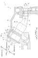
- FIG. 2 is a cross-sectional view showing the vicinity of a combustor. 2 is a diagram for explaining a structure of a main part of a combustor according to some embodiments.
- FIG. FIG. 13 is a cross-sectional view of an air hole plate of a combustor according to another embodiment.
- expressions indicating that things are in an equal state such as “identical,””equal,” and “homogeneous,” not only indicate a state of strict equality, but also indicate a state in which there is a tolerance or a difference to the extent that the same function is obtained.
- expressions describing shapes such as a rectangular shape or a cylindrical shape do not only refer to rectangular shapes, cylindrical shapes, etc. in the strict geometric sense, but also refer to shapes that include uneven portions, chamfered portions, etc., to the extent that the same effect is obtained.
- the expressions “comprise,””include,””have,””includes,” or “have” of one element are not exclusive expressions excluding the presence of other elements.
- Figure 1 is a schematic configuration diagram of a gas turbine according to one embodiment.
- Figure 2 is a cross-sectional view showing the vicinity of a combustor 4.
- the gas turbine 1 includes a compressor 2 for generating compressed air, a gas turbine combustor (combustor) 4 for generating combustion gas using the compressed air and fuel, and a turbine 6 configured to be rotationally driven by the combustion gas.
- a generator (not shown) is connected to the turbine 6.
- the compressor 2 includes a plurality of stator vanes 16 fixed to a casing 11 of a compressor casing 10 via a blade ring (not shown), and a plurality of rotor blades 18 implanted in the rotor 8 so as to be arranged alternately with respect to the stator vanes 16. Air taken in through an air intake 12 is sent to the compressor 2, and this air passes through a plurality of stator vanes 16 and a plurality of rotor blades 18 and is compressed to become high-temperature, high-pressure compressed air.
- the combustor 4 is supplied with fuel and compressed air generated by the compressor 2, and the fuel is combusted in the combustor 4 to generate combustion gas G, which is a working fluid for the turbine 6.
- the gas turbine 1 has a plurality of combustors 4 arranged in a casing 20 that defines a combustor casing 40, in the circumferential direction around a rotor 8. Compressed air compressed by the compressor 2 is supplied to the combustor casing 40 .
- the turbine 6 includes a plurality of stator vanes 24 and rotor blades 26 provided in a combustion gas passage 27 in a turbine casing 22.
- the stator vanes 24 and rotor blades 26 of the turbine 6 are provided downstream of the combustor 4 with respect to the flow of the combustion gas G (downstream in the axial direction of the rotor 8).
- the downstream side in the flow direction of the combustion gas G in the combustion gas passage 27 is referred to as the downstream side in the axial direction of the rotor 8
- the upstream side in the flow direction of the combustion gas G in the combustion gas passage 27 is referred to as the upstream side in the axial direction of the rotor 8.
- the stator vanes 24 are fixed to the turbine casing 22 side, and a plurality of the stator vanes 24 arranged along the circumferential direction of the rotor 8 constitute a stator vane row.
- the moving blades 26 are implanted in the rotor 8, and a plurality of the moving blades 26 arranged along the circumferential direction of the rotor 8 constitute a moving blade row.
- the stator vane rows and moving blade rows are arranged alternately in the axial direction of the rotor 8.
- the combustion gas G from the combustor 4 that has flowed into a combustion gas passage 27 passes through the plurality of stator vanes 24 and the plurality of rotor blades 26 from the upstream side to the downstream side in the axial direction of the rotor 8, thereby driving the rotor 8 to rotate, and thereby driving a generator connected to the rotor 8 to generate electric power.
- the combustion gas G is exhausted to the outside via an exhaust chamber 30.
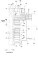
- FIG. 3 is a diagram for explaining the structure of the main parts of the combustor 4 according to some embodiments.
- the combustor 4 includes a combustion liner 54 having a combustion chamber 52 therein, an air hole plate 56 having a plurality of air holes 58 formed therein and located upstream of the combustion liner 54, a tubular member 60 located on the opposite side of the combustion liner 54 from the air hole plate 56, and a top hat portion 70 having a head end portion 72 located on the opposite side of the tubular member 60 from the air hole plate 56.
- the direction in which the central axis AX of the combustion cylinder 54 extends is also simply referred to as the axial direction.
- the downstream side in the flow direction of the combustion gas G in the combustion cylinder 54 is also simply referred to as the axial downstream side or the downstream side
- the upstream side in the flow direction of the combustion gas G in the combustion cylinder 54 is also simply referred to as the axial upstream side or the upstream side.
- the circumferential direction around the central axis AX of the combustion cylinder 54 is also simply referred to as the circumferential direction.
- the central axis AX of the combustion cylinder 54 will be extended upstream, and the orientations of the air hole plate 56, the tubular member 60, and the top hat portion 70 will also be explained based on the central axis AX of the combustion cylinder 54.
- a transition piece 55 is provided downstream of the combustion tube 54.
- the transition piece 55 may be integrally formed with the combustion tube 54.
- the air hole plate 56 is, for example, a thick disk-shaped member in which a plurality of through holes extending in the thickness direction are formed as the air holes 58.
- the air hole plate 56 is formed with the above-mentioned plurality of air holes 58 extending in the extension direction of the central axis AX of the combustion cylinder 54.
- the air hole plate 56 is attached to a tubular member 60 which will be described later.
- the tubular member 60 has an internal space 64 extending in the axial direction therein, and is located on the axial upstream side of the air hole plate 56, opposite the combustion liner 54.
- the tubular member 60 has an opening 62 formed in a side portion 60s of the tubular member 60, for taking in compressed air (hereinafter also simply referred to as air) in the combustor casing 40 into the internal space 64.
- the opening 62 has a relatively short flow passage 60c extending radially from an outer opening end 62a facing radially outward of the tubular member 60 to an inner opening end 62b facing radially inward of the tubular member 60.
- the opening 62 has a bell-mouth shape in which an inner circumferential surface 60i defining the flow passage 60c is formed so that the flow passage area decreases from the outer opening end 62a toward the radially inward direction. That is, the opening 62 has a guide portion 66 for guiding the compressed air flowing in from the side of the tubular member 60 into the internal space 64 of the tubular member 60.
- a plurality of openings 62 are formed around the entire circumference of the side portion 60s of the cylindrical member 60 in an upstream region at intervals in the circumferential direction.
- the internal space 64 of the tubular member 60 extends in the axial direction, and the opening 62 having the relatively short flow passage 60c extending in the radial direction is located in the upstream region of the side portion 60s. Therefore, when viewed in cross section along the axial direction, the tubular member 60 forms an L-shaped flow passage through which compressed air can flow, consisting of the flow passage 60c and the internal space 64.
- a plurality of fuel nozzles 80 are disposed in the internal space 64 of the cylindrical member 60.
- the plurality of fuel nozzles 80 are provided to correspond to the plurality of air holes 58, respectively, and each extend in the axial direction.
- the top hat portion 70 includes a head end portion 72 located on the axial upstream side of the cylindrical member 60, and a flange portion 74 formed at a position away from the head end portion 72 on the axial upstream side and attached to the casing 20 that defines the combustor casing 40 (see FIG. 2 ).
- the top hat portion 70 is configured to be positioned in the inlet portion 21 that defines a cylindrical space 21 a that protrudes from the inner circumferential surface 20 i of the casing 20 that defines the combustor chamber 40 toward the outside of the combustor chamber 40.
- the compressed air in the combustor casing 40 flows from the opening 62 into the internal space 64 of the tubular member 60 and flows toward the multiple air holes 58 in the air hole plate 56.
- the compressed air flows radially inward along the flow path 60c of the opening 62 and flows into the internal space 64, and then changes its flow direction by 90 degrees axially downstream and flows toward the multiple air holes 58 in the air hole plate 56.
- the compressed air that has flowed into the internal space 64 flows into the multiple air holes 58 of the air hole plate 56 and flows downstream while being mixed with fuel injected from the multiple fuel nozzles 80 within the multiple air holes 58.
- the fuel and air mixed in the air hole plate 56 are ignited by an ignition device (not shown), and a flame is formed in the combustion chamber 52 in the combustion tube 54 to generate combustion gas G.
- FIG. 4 is a cross-sectional view of an air hole plate 56 of a combustor 4 according to another embodiment.
- a fuel injection hole 53 is provided on an inner circumferential surface 58 i of each of the plurality of air holes 58 , and fuel can be injected from this fuel injection hole 53 into the air hole 58 . That is, in some embodiments of the combustor 4, instead of injecting fuel into each of the plurality of air holes 58 from the plurality of fuel nozzles 80 arranged in the internal space 64 of the cylindrical member 60, fuel may be injected into the air holes 58 from the fuel injection holes 53 provided on the inner circumferential surfaces 58i of each of the plurality of air holes 58.
- the combustor 4 may have the following features. That is, in the combustor 4 according to some embodiments, when the top hat portion 70 is attached to the casing 20 that defines the combustor casing 40, at least a portion of the opening 62 may be located more inward of the combustor casing 40 than the inner circumferential surface 20i of the casing 20. Note that in the combustor 4 illustrated in FIG. 2 , the entire opening 62 is configured to be located more inward of the combustor casing 40 than the inner circumferential surface 20i of the casing 20.
- the flow rate of the compressed air in the combustor casing 40 when it flows into the opening 62 can be suppressed.
- the opening 62 is formed in the side portion 60s of the tubular member 60, it is easy to make the opening area of the opening 62 relatively large, so the flow rate of the compressed air in the combustor casing 40 when it flows into the opening 62 can be suppressed. This makes it possible to reduce bias in the air flow rate of the compressed air flowing from the internal space 64 of the tubular member 60 into the multiple air holes 58.
- the gas turbine 1 equipped with the combustor 4 according to some of the embodiments described above, as described above, it is possible to reduce the bias in the air flow rate of the compressed air flowing from the internal space 64 of the cylindrical member 60 into the multiple air holes 58, thereby reducing NOx emissions and reducing the pressure loss when passing through each air hole 58, thereby reducing the decrease in the efficiency of the entire gas turbine 1.
- the opening 62 may be formed in a position along the axial direction closer to the head end portion 72 than the air hole plate 56. That is, as described above, the opening 62 may be formed in the upstream region of the side portion 60s of the tubular member 60. In order for the flow of compressed air that has flowed from the side portion 60s of the cylindrical member 60 through the opening 62 into the internal space 64 of the cylindrical member 60 to be redirected axially downstream, it is desirable to ensure a certain degree of axial distance from the opening 62 to the air hole plate 56.
- the axial distance from the opening 62 to the air hole plate 56 can be made longer than when the opening 62 is formed in the downstream region of the side portion 60s, and therefore bias in the air flow rate of the compressed air flowing into the multiple air holes 58 can be reduced.
- the opening 62 may have a guide portion 66 for guiding air flowing from the side of the tubular member 60 into the internal space 64 of the tubular member 60 . This makes it difficult for the flow of compressed air flowing into the internal space 64 of the tubular member 60 to become turbulent, thereby reducing bias in the air flow rate of the compressed air flowing into the multiple air holes 58.
- the opening 62 may be configured to be located more inside the combustor casing 40 than the inner circumferential surface 20i of the casing 20. This makes it possible to further suppress the flow velocity of the compressed air inside the combustor casing 40 when it flows into the opening 62. Therefore, it is possible to further reduce the bias in the air flow rate of the compressed air flowing from the internal space 64 of the cylindrical member 60 into the multiple air holes 58.
- the combustor 4 may include a plurality of fuel nozzles 80 extending in the axial direction corresponding to the plurality of air holes 58, respectively.
- the plurality of fuel nozzles 80 may be disposed within the internal space 64 of the tubular member 60. This makes it easier for the compressed air to flow in the axial direction along the outer periphery 80 a of the multiple fuel nozzles 80 arranged in the internal space 64 of the tubular member 60 .
- the tubular member 60 may be attached to the head end portion 72 as shown in FIG. This makes it possible to realize support of the tubular member 60, at least a portion of which is located inside the combustor casing 40, with a simple structure.
- the top hat portion 70 having the head end portion 72 is attached to the casing by a flange portion 74. Therefore, the tubular member 60 is attached to the casing via the top hat portion 70.
- the top hat portion 70 may have a flange portion 74 attached to the casing 20.
- the head end portion 72 may be formed at a position axially separated from the flange portion 74 toward the tubular member 60, i.e., at a position axially separated from the flange portion 74 downstream. This allows the tubular member 60 to be brought closer to the combustor casing 40 , which is located axially downstream from the flange portion 74 .
- the axial positional relationship between the flange portion 74 and the head end portion 72 of the top hat portion 70 be specified such that, when the flange portion 74 is attached to the casing 20, at least a part of the opening 62 of the tubular member 60 attached to the head end portion 72 is positioned more inside the combustor chamber 40 than the inner circumferential surface 20i of the casing 20.
- a gas turbine combustor 4 includes a combustion liner 54 having a combustion chamber 52 therein, an air hole plate 56 in which a plurality of air holes 58 extending in an axial direction of the combustion liner 54 are formed and which is located upstream of the combustion liner 54, a tubular member 60 having an internal space 64 extending in the axial direction therein and which is located on the opposite side of the combustion liner 54 with respect to the air hole plate 56, and a top hat portion 70 having a head end portion 72 located on the opposite side of the air hole plate 56 with respect to the tubular member 60.
- the tubular member 60 has an opening 62 formed in a side portion 60s of the tubular member 60 for taking in air within the combustor casing 40 into the internal space 64. At least a portion of the opening 62 is configured to be located more inside the combustor casing 40 than an inner circumferential surface 20i of the casing 20 when the top hat portion 70 is attached to a casing 20 that defines the combustor casing 40.
- the gas turbine combustor 4 is configured so that at least a portion of the opening 62 formed in the side portion 60s of the tubular member 60 is located inside the combustor casing 40 relative to the inner circumferential surface 20i of the casing 20, so that the flow rate of the compressed air in the combustor casing 40 flowing into the opening 62 can be suppressed.
- the opening area of the opening 62 since it is relatively easy to make the opening area of the opening 62 large, the flow rate of the compressed air in the combustor casing 40 flowing into the opening 62 can be suppressed. This suppresses separation of the compressed air flowing from the internal space 64 of the tubular member 60 into the multiple air holes 58, and also reduces bias in the air flow rate of the compressed air.
- the opening 62 may be formed at a position along the axial direction closer to the head end portion 72 than the air hole plate 56.
- the axial distance from the opening 62 to the air hole plate 56 can be made longer than when the opening 62 is formed axially closer to the air hole plate 56 than the head end portion 72, thereby reducing bias in the air flow rate of the compressed air flowing into the multiple air holes 58.
- the opening 62 may have a guide portion 66 for guiding air flowing into the internal space 64 of the tubular member 60 from the side of the tubular member 60.
- the configuration (3) above makes it difficult for the flow of compressed air flowing into the internal space 64 of the cylindrical member 60 to become turbulent, reducing bias in the air flow rate of the compressed air flowing into the multiple air holes 58.
- the opening 62 may be configured to be located inside the combustor casing 40 relative to the inner circumferential surface 20i when the top hat portion 70 is attached to the casing 20.
- the configuration of (4) above can further reduce the flow rate of the compressed air in the combustor casing 40 as it flows into the opening 62. This can further reduce the bias in the air flow rate of the compressed air flowing from the internal space 64 of the cylindrical member 60 into the multiple air holes 58.
- the configurations (1) to (4) above may include a plurality of fuel nozzles 80 extending in the axial direction, each of which corresponds to one of the plurality of air holes 58.
- the plurality of fuel nozzles 80 may be disposed within the internal space 64 of the tubular member 60.
- the configuration (5) above makes it easier for compressed air to flow axially along the outer periphery 80a of the multiple fuel nozzles 80 arranged within the internal space 64 of the cylindrical member 60.
- the tubular member 60 may be attached to the head end portion 72.
- the above configuration (6) allows for a simple structure to support the tubular member 60, at least a portion of which is located inside the combustor casing 40.
- the top hat portion 70 may have a flange portion 74 that is attached to the casing 20.
- the head end portion 72 may be formed at a position axially away from the flange portion 74 toward the tubular member 60.
- the configuration (7) above allows the tubular member 60 to be brought closer to the combustor chamber 40, which is axially separated from the flange portion 74.
- a gas turbine 1 includes a gas turbine combustor 4 having the configurations (1) to (7) described above, and a casing 20 that defines a combustor casing 40.
- the above configuration (8) can reduce bias in the air flow rate of the compressed air flowing from the internal space 64 of the cylindrical member 60 into the multiple air holes 58, thereby reducing NOx emissions and reducing the pressure loss when passing through each air hole 58, thereby reducing the decrease in efficiency of the entire gas turbine 1.
Landscapes
- Engineering & Computer Science (AREA)
- Chemical & Material Sciences (AREA)
- Combustion & Propulsion (AREA)
- Mechanical Engineering (AREA)
- General Engineering & Computer Science (AREA)
Abstract
Description
本願は、2023年6月13日に日本国特許庁に出願された特願2023-097170号に基づき優先権を主張し、その内容をここに援用する。
燃焼室を内側に有する燃焼筒と、
前記燃焼筒の軸方向に延在する複数の空気孔が形成され、前記燃焼筒の上流側に位置する空気孔プレートと、
前記軸方向に延在する内部空間を内部に有し、前記空気孔プレートに対して前記燃焼筒とは反対側に位置する筒状部材と、
前記筒状部材に対して前記空気孔プレートとは反対側に位置するヘッドエンド部を有するトップハット部と、
を備え、
前記筒状部材は、前記筒状部材の側部に形成されていて前記内部空間に前記燃焼器車室内の空気を取り入れるための開口部を有し、
前記開口部の少なくとも一部は、前記トップハット部が燃焼器車室を画定するケーシングに取り付けられると、前記ケーシングの内周面よりも前記燃焼器車室の内部に位置するように構成されている。
上記(1)の構成のガスタービン燃焼器と、
前記燃焼器車室を画定する前記ケーシングと、
を備える。
例えば、「ある方向に」、「ある方向に沿って」、「平行」、「直交」、「中心」、「同心」或いは「同軸」等の相対的或いは絶対的な配置を表す表現は、厳密にそのような配置を表すのみならず、公差、若しくは、同じ機能が得られる程度の角度や距離をもって相対的に変位している状態も表すものとする。
例えば、「同一」、「等しい」及び「均質」等の物事が等しい状態であることを表す表現は、厳密に等しい状態を表すのみならず、公差、若しくは、同じ機能が得られる程度の差が存在している状態も表すものとする。
例えば、四角形状や円筒形状等の形状を表す表現は、幾何学的に厳密な意味での四角形状や円筒形状等の形状を表すのみならず、同じ効果が得られる範囲で、凹凸部や面取り部等を含む形状も表すものとする。
一方、一の構成要素を「備える」、「具える」、「具備する」、「含む」、又は、「有する」という表現は、他の構成要素の存在を除外する排他的な表現ではない。
図1に示すように、ガスタービン1は、圧縮空気を生成するための圧縮機2と、圧縮空気及び燃料を用いて燃焼ガスを発生させるためのガスタービン燃焼器(燃焼器)4と、燃焼ガスによって回転駆動されるように構成されたタービン6と、を備える。発電用のガスタービン1の場合、タービン6には不図示の発電機が連結される。
圧縮機2には、空気取入口12から取り込まれた空気が送られるようになっており、この空気は、複数の静翼16及び複数の動翼18を通過して圧縮されることで高温高圧の圧縮空気となる。
燃焼器車室40内には、圧縮機2で圧縮された圧縮空気が供給されるようになっている。
なお、以下の説明では。ロータ8の軸方向に関し、燃焼ガス通路27内の燃焼ガスGの流れる方向の下流側をロータ8の軸方向の下流側と称し、燃焼ガス通路27内の燃焼ガスGの流れる方向の上流側をロータ8の軸方向の上流側と称する。
タービン6では、燃焼ガス通路27に流れ込んだ燃焼器4からの燃焼ガスGが複数の静翼24及び複数の動翼26をロータ8の軸方向の上流側から下流側に向かって通過することでロータ8が回転駆動され、これにより、ロータ8に連結された発電機が駆動されて電力が生成されるようになっている。タービン6を駆動した後の燃焼ガスGは、排気室30を介して外部へ排出される。
また、説明の便宜上、燃焼筒54の中心軸AXを上流側に延ばし、空気孔プレート56、筒状部材60、及びトップハット部70の向きについても燃焼筒54の中心軸AXを基準として説明することとする。
幾つかの実施形態に係る燃焼器4では、空気孔プレート56は、例えば厚肉の円盤状の部材に対して厚さ方向に延在する複数の貫通孔が空気孔58として形成された部材である。空気孔プレート56は、燃焼筒54の中心軸AXの延在方向に延在する上述した複数の空気孔58が形成されている。
幾つかの実施形態に係る燃焼器4では、空気孔プレート56は、後述する筒状部材60に取り付けられている。
幾つかの実施形態に係る燃焼器4では、筒状部材60は、軸方向に延在する内部空間64を内部に有し、空気孔プレート56に対して燃焼筒54とは反対側である軸方向上流側に位置している。筒状部材60は、筒状部材60の側部60sに形成されていて内部空間64に燃焼器車室40内の圧縮空気(以下単に空気とも称する)を取り入れるための開口部62を有する。
開口部62は、筒状部材60の側部60sの内、上流側の領域において周方向に間隔を空けて全周にわたって複数形成されている。
図3に示す燃焼器4では、筒状部材60の内部空間64には、複数の燃料ノズル80が配置されている。複数の燃料ノズル80は、複数の空気孔58のそれぞれに対応するように設けられていて、軸方向にそれぞれ延在する。
幾つかの実施形態に係る燃焼器4では、トップハット部70は、筒状部材60の軸方向上流側に位置するヘッドエンド部72と、ヘッドエンド部72よりも軸方向上流側に離れた位置に形成されていて燃焼器車室40を画定するケーシング20に取り付けられるフランジ部74と、を有する(図2参照)。
トップハット部70は、フランジ部74がケーシング20に取り付けられると、燃焼器車室40を画定するケーシング20の内周面20iから燃焼器車室40の外部に向かって突出する筒状の空間21aを画定する入口部21に位置するように構成されている。
空気孔プレート56で混合された燃料と空気とは、不図示の着火装置により着火されて、燃焼筒54内の燃焼室52に火炎が形成されて燃焼ガスGを生成する。
他の実施形態に係る燃焼器4では、複数の空気孔58のそれぞれの内周面58iに燃料噴射孔53を設け、この燃料噴射孔53から空気孔58内に燃料を噴射可能である。
すなわち幾つかの実施形態に係る燃焼器4では、筒状部材60の内部空間64に配置された複数の燃料ノズル80から複数の空気孔58のそれぞれに燃料を噴射するのではなく、複数の空気孔58のそれぞれの内周面58iに設けた燃料噴射孔53から空気孔58内に燃料を噴射するようにしてもよい。
すなわち幾つかの実施形態に係る燃焼器4では、開口部62の少なくとも一部は、トップハット部70が燃焼器車室40を画定するケーシング20に取り付けられると、ケーシング20の内周面20iよりも燃焼器車室40の内部に位置するように構成されているとよい。なお、図2に示す燃焼器4では、開口部62の全体がケーシング20の内周面20iよりも燃焼器車室40の内部に位置するように構成されている。
筒状部材60の側部60sから開口部62を介して筒状部材60の内部空間64に流入した圧縮空気の流れの向きが軸方向下流側に転向するためには、開口部62から空気孔プレート56までの軸方向の距離がある程度確保されることが望ましい。そのため、開口部62が側部60sの内、上流側の領域に形成されていれば、開口部62が側部60sの内、下流側の領域に形成されている場合と比べて開口部62から空気孔プレート56までの軸方向の距離を長くすることができるので、複数の空気孔58に流入する圧縮空気の空気流量の偏りを低減できる。
これにより、筒状部材60の内部空間64に流入する圧縮空気の流れが乱れにくくなり、複数の空気孔58に流入する圧縮空気の空気流量の偏りを低減できる。
これにより、燃焼器車室40内の圧縮空気が開口部62に流入する際の流速を一層抑制できる。よって、筒状部材60の内部空間64から複数の空気孔58に流入する圧縮空気の空気流量の偏りを一層低減できる。
これにより、筒状部材60の内部空間64内に配置された複数の燃料ノズル80の外周部80aに沿って軸方向に圧縮空気が流れ易くなる。
これにより、少なくとも一部が燃焼器車室40内に位置することとなる筒状部材60の支持を簡単な構成で実現できる。
なお、ヘッドエンド部72を有するトップハット部70は、フランジ部74でケーシングに取り付けられている。よって、筒状部材60は、トップハット部70を介してケーシングに取り付けられていることとなる。
これにより、筒状部材60をフランジ部74から軸方向下流側に離れた燃焼器車室40に近づけることができる。
これにより、開口部62の少なくとも一部がケーシング20の内周面20iよりも燃焼器車室40の内部に位置するように筒状部材60を容易に配置できる。
(1)本開示の少なくとも一実施形態に係るガスタービン燃焼器4は、燃焼室52を内側に有する燃焼筒54と、燃焼筒54の軸方向に延在する複数の空気孔58が形成され、燃焼筒54の上流側に位置する空気孔プレート56と、軸方向に延在する内部空間64を内部に有し、空気孔プレート56に対して燃焼筒54とは反対側に位置する筒状部材60と、筒状部材60に対して空気孔プレート56とは反対側に位置するヘッドエンド部72を有するトップハット部70と、を備える。筒状部材60は、筒状部材60の側部60sに形成されていて内部空間64に燃焼器車室40内の空気を取り入れるための開口部62を有する。開口部62の少なくとも一部は、トップハット部70が燃焼器車室40を画定するケーシング20に取り付けられると、ケーシング20の内周面20iよりも燃焼器車室40の内部に位置するように構成されている。
上記(2)の構成によれば、開口部62が軸方向に沿ってヘッドエンド部72よりも空気孔プレート56に近い位置に形成されている場合と比べて開口部62から空気孔プレート56までの軸方向の距離を長くすることができるので、複数の空気孔58に流入する圧縮空気の空気流量の偏りを低減できる。
2 圧縮機
4 ガスタービン燃焼器(燃焼器)
6 タービン
8 ロータ
20 ケーシング
20i 内周面
21 入口部
21a 空間
40 燃焼器車室
52 燃焼室
54 燃焼筒
56 空気孔プレート
58 空気孔
60 筒状部材
60s 側部
62 開口部
64 内部空間
66 案内部
70 トップハット部
72 ヘッドエンド部
74 フランジ部
80 燃料ノズル
Claims (8)
- 燃焼室を内側に有する燃焼筒と、
前記燃焼筒の軸方向に延在する複数の空気孔が形成され、前記燃焼筒の上流側に位置する空気孔プレートと、
前記軸方向に延在する内部空間を内部に有し、前記空気孔プレートに対して前記燃焼筒とは反対側に位置する筒状部材と、
前記筒状部材に対して前記空気孔プレートとは反対側に位置するヘッドエンド部を有するトップハット部と、
を備え、
前記筒状部材は、前記筒状部材の側部に形成されていて前記内部空間に燃焼器車室内の空気を取り入れるための開口部を有し、
前記開口部の少なくとも一部は、前記トップハット部が燃焼器車室を画定するケーシングに取り付けられると、前記ケーシングの内周面よりも前記燃焼器車室の内部に位置するように構成されている、
ガスタービン燃焼器。 - 前記開口部は、前記軸方向に沿って前記空気孔プレートよりも前記ヘッドエンド部に近い位置に形成されている、
請求項1に記載のガスタービン燃焼器。 - 前記開口部は、前記筒状部材の前記内部空間に前記筒状部材の側方から流入する空気を案内するための案内部、
を有する、
請求項1又は2に記載のガスタービン燃焼器。 - 前記開口部は、前記トップハット部が前記ケーシングに取り付けられると、前記内周面よりも前記燃焼器車室の内部に位置するように構成されている、
請求項1又は2に記載のガスタービン燃焼器。 - 前記複数の空気孔のそれぞれに対応する、前記軸方向に延在する複数の燃料ノズル、
を備え、
前記複数の燃料ノズルは、前記筒状部材の前記内部空間内に配置されている、
請求項1又は2に記載のガスタービン燃焼器。 - 前記筒状部材は、前記ヘッドエンド部に取り付けられている、
請求項1又は2に記載のガスタービン燃焼器。 - 前記トップハット部は、前記ケーシングに取り付けられるフランジ部、
を有し、
前記ヘッドエンド部は、前記筒状部材に向かって前記フランジ部から前記軸方向に離れた位置に形成されている、
請求項1又は2に記載のガスタービン燃焼器。 - 請求項1又は2に記載のガスタービン燃焼器と、
前記燃焼器車室を画定する前記ケーシングと、
を備える、
ガスタービン。
Priority Applications (4)
| Application Number | Priority Date | Filing Date | Title |
|---|---|---|---|
| KR1020257037111A KR20250171352A (ko) | 2023-06-13 | 2024-05-16 | 가스 터빈 연소기 및 가스 터빈 |
| JP2025527585A JPWO2024257547A1 (ja) | 2023-06-13 | 2024-05-16 | |
| DE112024001583.2T DE112024001583T5 (de) | 2023-06-13 | 2024-05-16 | Gasturbinenbrennkammer und gasturbine |
| CN202480031931.XA CN121152943A (zh) | 2023-06-13 | 2024-05-16 | 燃气涡轮燃烧器及燃气涡轮 |
Applications Claiming Priority (2)
| Application Number | Priority Date | Filing Date | Title |
|---|---|---|---|
| JP2023-097170 | 2023-06-13 | ||
| JP2023097170 | 2023-06-13 |
Publications (1)
| Publication Number | Publication Date |
|---|---|
| WO2024257547A1 true WO2024257547A1 (ja) | 2024-12-19 |
Family
ID=93852085
Family Applications (1)
| Application Number | Title | Priority Date | Filing Date |
|---|---|---|---|
| PCT/JP2024/018174 Ceased WO2024257547A1 (ja) | 2023-06-13 | 2024-05-16 | ガスタービン燃焼器及びガスタービン |
Country Status (5)
| Country | Link |
|---|---|
| JP (1) | JPWO2024257547A1 (ja) |
| KR (1) | KR20250171352A (ja) |
| CN (1) | CN121152943A (ja) |
| DE (1) | DE112024001583T5 (ja) |
| WO (1) | WO2024257547A1 (ja) |
Citations (6)
| Publication number | Priority date | Publication date | Assignee | Title |
|---|---|---|---|---|
| JPS5888565U (ja) * | 1981-12-04 | 1983-06-15 | 三菱重工業株式会社 | ガスタ−ビン燃焼器 |
| JP2001289441A (ja) * | 2000-04-10 | 2001-10-19 | Mitsubishi Heavy Ind Ltd | ガスタービン燃焼器 |
| JP2015209842A (ja) * | 2014-04-30 | 2015-11-24 | 三菱日立パワーシステムズ株式会社 | ガスタービン燃焼器、ガスタービン、制御装置及び制御方法 |
| WO2015190169A1 (ja) * | 2014-06-09 | 2015-12-17 | 三菱日立パワーシステムズ株式会社 | 回転機械及び回転機械の組立方法、回転機械のメンテナンス方法 |
| JP2016061545A (ja) * | 2014-09-22 | 2016-04-25 | 三菱日立パワーシステムズ株式会社 | 燃焼器、及びこれを備えているガスタービン |
| WO2021193434A1 (ja) * | 2020-03-23 | 2021-09-30 | 三菱重工業株式会社 | 燃焼器、及びこれを備えるガスタービン |
Family Cites Families (1)
| Publication number | Priority date | Publication date | Assignee | Title |
|---|---|---|---|---|
| JP3960166B2 (ja) | 2001-08-29 | 2007-08-15 | 株式会社日立製作所 | ガスタービン燃焼器およびガスタービン燃焼器の運転方法 |
-
2024
- 2024-05-16 WO PCT/JP2024/018174 patent/WO2024257547A1/ja not_active Ceased
- 2024-05-16 CN CN202480031931.XA patent/CN121152943A/zh active Pending
- 2024-05-16 DE DE112024001583.2T patent/DE112024001583T5/de active Pending
- 2024-05-16 JP JP2025527585A patent/JPWO2024257547A1/ja active Pending
- 2024-05-16 KR KR1020257037111A patent/KR20250171352A/ko active Pending
Patent Citations (6)
| Publication number | Priority date | Publication date | Assignee | Title |
|---|---|---|---|---|
| JPS5888565U (ja) * | 1981-12-04 | 1983-06-15 | 三菱重工業株式会社 | ガスタ−ビン燃焼器 |
| JP2001289441A (ja) * | 2000-04-10 | 2001-10-19 | Mitsubishi Heavy Ind Ltd | ガスタービン燃焼器 |
| JP2015209842A (ja) * | 2014-04-30 | 2015-11-24 | 三菱日立パワーシステムズ株式会社 | ガスタービン燃焼器、ガスタービン、制御装置及び制御方法 |
| WO2015190169A1 (ja) * | 2014-06-09 | 2015-12-17 | 三菱日立パワーシステムズ株式会社 | 回転機械及び回転機械の組立方法、回転機械のメンテナンス方法 |
| JP2016061545A (ja) * | 2014-09-22 | 2016-04-25 | 三菱日立パワーシステムズ株式会社 | 燃焼器、及びこれを備えているガスタービン |
| WO2021193434A1 (ja) * | 2020-03-23 | 2021-09-30 | 三菱重工業株式会社 | 燃焼器、及びこれを備えるガスタービン |
Also Published As
| Publication number | Publication date |
|---|---|
| KR20250171352A (ko) | 2025-12-08 |
| JPWO2024257547A1 (ja) | 2024-12-19 |
| DE112024001583T5 (de) | 2026-01-15 |
| CN121152943A (zh) | 2025-12-16 |
Similar Documents
| Publication | Publication Date | Title |
|---|---|---|
| US10317078B2 (en) | Cooling a multi-walled structure of a turbine engine | |
| US8397514B2 (en) | System and method for flow control in gas turbine engine | |
| JP7112342B2 (ja) | ガスタービン燃焼器及びガスタービン | |
| US9303872B2 (en) | Fuel injector | |
| CN113167474B (zh) | 燃气轮机的燃烧器以及具备该燃烧器的燃气轮机 | |
| KR20170107382A (ko) | 가스 터빈 유동 슬리브 장착 | |
| KR102452772B1 (ko) | 가스 터빈의 연료 노즐 및 연소기 및 가스 터빈 | |
| CN113864818B (zh) | 燃烧器空气流动路径 | |
| WO2012157498A1 (ja) | ガスタービンエンジン | |
| CN213577573U (zh) | 燃烧器的燃料喷嘴、燃烧器以及燃气轮机 | |
| KR20210148971A (ko) | 연소 라이너 냉각 | |
| US11209163B2 (en) | Gas turbine combustor, manufacturing method for gas turbine and gas turbine combustor | |
| CN108954381B (zh) | 燃料喷嘴总成、燃料喷嘴模块以及燃气轮机 | |
| JP2025117173A (ja) | ガスタービン用燃焼器 | |
| CN121152943A (zh) | 燃气涡轮燃烧器及燃气涡轮 | |
| JP7782063B2 (ja) | ガスタービンの燃焼筒、ガスタービンの燃焼器及びガスタービン | |
| CN107191966B (zh) | 燃烧衬套冷却 | |
| JP7696453B2 (ja) | 燃焼器及びガスタービン | |
| JP7487329B2 (ja) | ガスタービン燃焼器及びガスタービン | |
| WO2025211263A1 (ja) | ガスタービンの燃焼筒、ガスタービンの燃焼器及びガスタービン | |
| KR102154221B1 (ko) | 연료 선회 분사형의 연료분사부재를 포함하는 연소기 및 가스터빈 | |
| JP2025116829A (ja) | 燃焼器用の燃料噴射アセンブリ並びに該燃料噴射アセンブリを備える軸方向燃料ステージング燃焼器 | |
| WO2024202124A1 (ja) | バーナー集合体、ガスタービン燃焼器及びガスタービン |
Legal Events
| Date | Code | Title | Description |
|---|---|---|---|
| 121 | Ep: the epo has been informed by wipo that ep was designated in this application |
Ref document number: 24823169 Country of ref document: EP Kind code of ref document: A1 |
|
| ENP | Entry into the national phase |
Ref document number: 1020257037111 Country of ref document: KR Free format text: ST27 STATUS EVENT CODE: A-0-1-A10-A15-NAP-PA0105 (AS PROVIDED BY THE NATIONAL OFFICE) |
|
| WWE | Wipo information: entry into national phase |
Ref document number: KR1020257037111 Country of ref document: KR |
|
| ENP | Entry into the national phase |
Ref document number: 2025527585 Country of ref document: JP Kind code of ref document: A |
|
| WWE | Wipo information: entry into national phase |
Ref document number: 112024001583 Country of ref document: DE |
|
| WWP | Wipo information: published in national office |
Ref document number: 112024001583 Country of ref document: DE |