WO2024257538A1 - 車載センサ装置 - Google Patents
車載センサ装置 Download PDFInfo
- Publication number
- WO2024257538A1 WO2024257538A1 PCT/JP2024/017892 JP2024017892W WO2024257538A1 WO 2024257538 A1 WO2024257538 A1 WO 2024257538A1 JP 2024017892 W JP2024017892 W JP 2024017892W WO 2024257538 A1 WO2024257538 A1 WO 2024257538A1
- Authority
- WO
- WIPO (PCT)
- Prior art keywords
- sensor
- vehicle
- sound
- microphone
- sensor device
- Prior art date
- Legal status (The legal status is an assumption and is not a legal conclusion. Google has not performed a legal analysis and makes no representation as to the accuracy of the status listed.)
- Ceased
Links
Images











Classifications
-
- G—PHYSICS
- G01—MEASURING; TESTING
- G01S—RADIO DIRECTION-FINDING; RADIO NAVIGATION; DETERMINING DISTANCE OR VELOCITY BY USE OF RADIO WAVES; LOCATING OR PRESENCE-DETECTING BY USE OF THE REFLECTION OR RERADIATION OF RADIO WAVES; ANALOGOUS ARRANGEMENTS USING OTHER WAVES
- G01S7/00—Details of systems according to groups G01S13/00, G01S15/00, G01S17/00
- G01S7/52—Details of systems according to groups G01S13/00, G01S15/00, G01S17/00 of systems according to group G01S15/00
- G01S7/521—Constructional features
-
- G—PHYSICS
- G01—MEASURING; TESTING
- G01S—RADIO DIRECTION-FINDING; RADIO NAVIGATION; DETERMINING DISTANCE OR VELOCITY BY USE OF RADIO WAVES; LOCATING OR PRESENCE-DETECTING BY USE OF THE REFLECTION OR RERADIATION OF RADIO WAVES; ANALOGOUS ARRANGEMENTS USING OTHER WAVES
- G01S15/00—Systems using the reflection or reradiation of acoustic waves, e.g. sonar systems
- G01S15/88—Sonar systems specially adapted for specific applications
- G01S15/93—Sonar systems specially adapted for specific applications for anti-collision purposes
- G01S15/931—Sonar systems specially adapted for specific applications for anti-collision purposes of land vehicles
-
- G—PHYSICS
- G01—MEASURING; TESTING
- G01S—RADIO DIRECTION-FINDING; RADIO NAVIGATION; DETERMINING DISTANCE OR VELOCITY BY USE OF RADIO WAVES; LOCATING OR PRESENCE-DETECTING BY USE OF THE REFLECTION OR RERADIATION OF RADIO WAVES; ANALOGOUS ARRANGEMENTS USING OTHER WAVES
- G01S15/00—Systems using the reflection or reradiation of acoustic waves, e.g. sonar systems
- G01S15/02—Systems using the reflection or reradiation of acoustic waves, e.g. sonar systems using reflection of acoustic waves
- G01S15/06—Systems determining the position data of a target
- G01S15/08—Systems for measuring distance only
-
- G—PHYSICS
- G01—MEASURING; TESTING
- G01S—RADIO DIRECTION-FINDING; RADIO NAVIGATION; DETERMINING DISTANCE OR VELOCITY BY USE OF RADIO WAVES; LOCATING OR PRESENCE-DETECTING BY USE OF THE REFLECTION OR RERADIATION OF RADIO WAVES; ANALOGOUS ARRANGEMENTS USING OTHER WAVES
- G01S15/00—Systems using the reflection or reradiation of acoustic waves, e.g. sonar systems
- G01S15/88—Sonar systems specially adapted for specific applications
- G01S15/93—Sonar systems specially adapted for specific applications for anti-collision purposes
- G01S15/931—Sonar systems specially adapted for specific applications for anti-collision purposes of land vehicles
- G01S2015/937—Sonar systems specially adapted for specific applications for anti-collision purposes of land vehicles sensor installation details
- G01S2015/938—Sonar systems specially adapted for specific applications for anti-collision purposes of land vehicles sensor installation details in the bumper area
Definitions
- the disclosure in this specification relates to an on-board sensor device that is installed in a vehicle.
- Patent Document 1 describes a transducer array mounted on a vehicle. This transducer array transmits and receives acoustic signals such as ultrasonic waves, making it possible to measure the distance between the vehicle and surrounding objects.
- Acoustic signals include not only ultrasonic waves as disclosed in Patent Document 1, but also sounds and vibrations in the audible range.
- the complexity of the configuration can make installation difficult.
- the purpose of this disclosure is to provide an on-board sensor device that makes it easy to install a sound vibration sensor in a vehicle.
- one disclosed embodiment is an on-board sensor device mounted on a vehicle, which includes an ultrasonic sensor having a transceiver that receives and/or transmits ultrasonic waves, a sensor housing that houses at least a portion of the ultrasonic sensor, and a sound vibration sensor that is housed in the sensor housing together with the ultrasonic sensor and detects sounds or vibrations in the audible range.
- the sensor housing for the ultrasonic sensor also houses a sound vibration sensor that detects sound or vibration. Therefore, by mounting the ultrasonic sensor on a vehicle, it is possible to realize mounting the sound vibration sensor on the vehicle as well. As a result, it is possible to simplify the configuration compared to a configuration in which the sound vibration sensor is mounted on the vehicle as a separate configuration from the ultrasonic sensor. Therefore, it becomes easier to mount the sound vibration sensor on the vehicle.
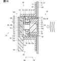
- FIG. 11 is a vertical cross-sectional view showing a configuration of an in-vehicle sensor device according to a third embodiment of the FIG. 11 is a vertical cross-sectional view showing a configuration of an in-vehicle sensor device according to a fourth embodiment of the present disclosure.
- FIG. 13 is a vertical cross-sectional view showing the configuration of an in-vehicle sensor device according to a fifth embodiment of the present disclosure.
- FIG. 13 is a vertical cross-sectional view showing the configuration of an in-vehicle sensor device according to a sixth embodiment of the present disclosure.
- FIG. 13 is a vertical cross-sectional view showing the configuration of an in-vehicle sensor device according to a fifth embodiment
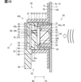
- FIG. 13 is a vertical cross-sectional view showing the configuration of an in-vehicle sensor device according to a seventh embodiment of 13 is a vertical cross-sectional view showing the configuration of an in-vehicle sensor device according to an eighth embodiment of the present disclosure.
- FIG. 13 is a vertical cross-sectional view showing the configuration of an in-vehicle sensor device according to a ninth embodiment
- FIG. 13 is a vertical cross-sectional view showing the configuration of an in-vehicle sensor device according to a tenth embodiment of the present disclosure.
- FIG. 23 is a vertical cross-sectional view showing the configuration of an in-vehicle sensor device according to an eleventh embodiment of the present disclosure.
- FIG. 23 is a longitudinal cross-sectional view showing the configuration of an in-vehicle sensor device according to a fifteenth embodiment of the present disclosure.
- FIG. 23 is a longitudinal cross-sectional view showing the configuration of an in-vehicle sensor device according to a sixteenth embodiment of the present disclosure.
- a vertical cross-sectional view showing the configuration of an in-vehicle sensor device according to a seventeenth embodiment of the present disclosure A vertical cross-sectional view showing the configuration of an in-vehicle sensor device according to an eighteenth embodiment of the present disclosure.
- FIG. 13 is a vertical cross-sectional view showing the configuration of an in-vehicle sensor device according to a twentieth embodiment of the present disclosure.
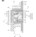
- the on-vehicle sensor device 100 is mounted on a vehicle Ve as shown in Figures 1 and 2.
- the on-vehicle sensor device 100 can be installed in various locations on the vehicle Ve, such as the front, side, and rear of the vehicle.
- the on-vehicle sensor device 100 is held in a plate-shaped external structure 10 of the vehicle Ve with an ultrasonic transmission/reception surface 24a exposed to the outer surface.
- the external structure 10 on the front of the vehicle is, for example, the front bumper center portion Pf1 and the front bumper corner portion Pf2.
- the on-board sensor device 100 installed on the external structure 10 on the front of the vehicle is oriented with the transmitting/receiving surface 24a facing the front Ze of the vehicle Ve, and is used to detect targets outside the vehicle Ve, mainly in the front Ze.
- the external structure 10 on the side of the vehicle is, for example, a front bumper side portion Ps1, a rear bumper side portion Ps2, a side mirror cover Ps3, and a side step Ps4.
- the on-board sensor device 100 installed on the external structure 10 on the side of the vehicle is oriented with the transmitting/receiving surface 24a facing the right Mi or left Hi of the vehicle Ve, and is used to detect targets outside the vehicle Ve, mainly on the sides.
- the external structure 10 on the rear of the vehicle is, for example, the rear bumper center portion Pb1 and the rear bumper corner portion Pb2.
- the on-board sensor device 100 installed on the external structure 10 on the rear of the vehicle is oriented with the transmitting/receiving surface 24a facing the rear Go of the vehicle Ve, and is used to detect targets outside the vehicle Ve, mainly in the rear Go.
- the front-rear and left-right directions in this disclosure are defined with respect to the vehicle Ve stationary on a horizontal plane.
- the front-rear direction (forward Ze and backward Go) is defined along the longitudinal direction (direction of travel) of the vehicle Ve.
- the left-right direction (right Mi and left Hi) is defined along the width direction of the vehicle Ve.
- the up-down direction (upward Ue) is defined along the vertical direction of the horizontal plane that defines the front-rear and left-right directions.
- the following description may omit the symbols indicating each direction as appropriate.
- the on-vehicle sensor device 100 includes an ultrasonic microphone 20 that receives and transmits ultrasonic waves, and a sound vibration sensor 70 that detects sounds or vibrations in the audible range.
- Ultrasonic waves are sound waves with high vibration frequencies that cannot be heard by the human ear, specifically, sound waves of 20 kHz or higher.
- the audible range is a frequency band lower than ultrasonic waves, specifically, the range from 20 Hz to 20 kHz.
- the on-vehicle sensor device 100 together with the external structure 10 and the adhesive layer 120, constitutes an on-vehicle sensor installation structure.
- the external structure 10 is, for example, a front bumper or a rear bumper, and is formed in a flat or slightly curved plate shape from a resin material such as polypropylene.
- the external structure 10 has a vehicle outer surface 11 that is exposed to the outside of the vehicle Ve in a position facing the front Ze, rear Go, or side of the vehicle Ve.
- the back side of the vehicle outer surface 11 is a smooth vehicle inner side surface 12 to which an adhesive layer 120 is attached.
- the external structure 10 has an attachment opening 15.
- the attachment opening 15 is a flat through hole that penetrates the external structure 10 in the plate thickness direction.
- the attachment opening 15 exposes the transmitting/receiving surface 24a of the vehicle-mounted sensor device 100 to the vehicle outer surface 11 side.
- the adhesive layer 120 is formed from a double-sided tape or adhesive material.
- the adhesive layer 120 is formed as a thin film that is thinner than the external structure 10.
- Each surface of the adhesive layer 120 is bonded to the vehicle inner surface 12 and the vehicle-mounted sensor device 100, respectively.
- the adhesive layer 120 fixes the vehicle-mounted sensor device 100 to the vehicle inner surface 12.
- the direction in which the vehicle outer surface 11 and the transmitting/receiving surface 24a face is referred to as the front side FS
- the direction in which the vehicle inner surface 12 faces is referred to as the rear side BS.
- the space on the front side FS from the external structure 10 is referred to as the outer space OS
- the space on the rear side BS from the rear surface (rear cover 50) of the vehicle-mounted sensor device 100 is referred to as the inner space IS
- the space around the vehicle-mounted sensor device 100 is referred to as the side space SS.
- the outer space OS is the space outside the vehicle from which ultrasonic waves and audible sounds arrive.
- the inner space IS is the space inside the vehicle Ve.
- the side space SS is the space located above, below, left and right of the vehicle-mounted sensor device 100 along the vehicle inner surface 12.
- the vehicle-mounted sensor device 100 is composed of an ultrasonic microphone 20, a sensor housing 30, a sound vibration sensor 70, a circuit board 80, and the like.
- the ultrasonic microphone 20 is configured to be able to transmit and receive ultrasonic waves.
- the ultrasonic microphone 20 transmits an ultrasonic exploration wave toward the outside space OS.
- the ultrasonic microphone 20 receives the exploration wave (reflected wave) reflected by an object present in the outside space OS, and outputs a detection signal according to the reception result of the reflected wave.
- the ultrasonic microphone 20 includes a microphone housing 21, a piezoelectric element 25, and a microphone filler 27.
- the microphone housing 21 is formed in a cylindrical shape with a bottom from a metal material such as aluminum.
- the microphone housing 21 has a receiving bottom 22 and a side wall 23.
- the receiving bottom 22 is formed in a thin plate shape at the bottom of the microphone housing 21.
- a piezoelectric element 25 is fixed to the inner surface of the receiving bottom 22.
- the receiving bottom 22 functions as a diaphragm, and together with the piezoelectric element 25 constitutes a transceiver 24 that receives and transmits ultrasonic waves.
- the outer surface of the receiving bottom 22 becomes a transmitting/receiving surface 24a exposed to the outer space OS when attached to the external structure 10 of the vehicle-mounted sensor device 100.
- the side wall 23 is formed in a cylindrical shape that surrounds the periphery of the receiving bottom 22.
- the piezoelectric element 25 is formed in a thin film.
- the piezoelectric element 25 is housed in the internal space of the microphone housing 21, which is partitioned (surrounded) by the receiving bottom 22 and the side wall 23.
- the piezoelectric element 25 is electrically connected to the circuit board 80 via the microphone lead wire 26.
- the piezoelectric element 25 generates minute vibrations based on the input electrical signal, enabling the transmitter/receiver 24 to transmit ultrasonic waves (search waves).
- the piezoelectric element 25 converts the vibrations of ultrasonic waves (reflected waves) arriving at the transmitter/receiver 24 into electrical signals, enabling the detection of reflected waves.
- the microphone filler 27 fills the internal space of the microphone housing 21 and is formed from silicone rubber or urethane foam that hardens within the internal space.
- the microphone filler 27 covers the transmitter/receiver 24 from the rear side BS and seals the piezoelectric element 25.
- the sensor housing 30 is a housing structure that houses an ultrasonic sensor, a sound vibration sensor 70, a circuit board 80, etc.
- the sensor housing 30 is composed of a housing body 40, a rear cover 50, a retainer 60, etc.
- the housing body 40 is formed in a box shape from a resin material such as polybutylene terephthalate (PBT).
- PBT polybutylene terephthalate
- the housing body 40 is formed with a housing peripheral wall 41, an intermediate partition wall 42, and a connector connection part 48.
- the housing peripheral wall 41 is formed in a cylindrical shape.
- the housing peripheral wall 41 has a microphone support portion 44, a cover fixing portion 45, and a board fixing portion 46.
- the microphone support portion 44 is formed on the inner peripheral surface of the housing peripheral wall 41 at a portion closer to the front side FS than the intermediate partition wall 42.
- the microphone support portion 44 supports the ultrasonic microphone 20 via a cushion portion 52 (described later).
- the cover fixing portion 45 is formed on the inner peripheral surface of the housing peripheral wall 41 at the end of the rear side BS.
- the cover fixing portion 45 holds the rear cover 50.
- the board fixing portion 46 is a stepped surface portion formed on the inner peripheral surface of the housing peripheral wall 41.
- the board fixing portion 46 is formed between the cover fixing portion 45 and the intermediate partition wall 42 in a position facing the rear side BS.
- the board fixing portion 46 supports the circuit board 80 from the front side FS.
- the intermediate partition wall 42 is erected from the inner peripheral surface of the housing peripheral wall 41 toward the inner peripheral side of the housing peripheral wall 41.
- the intermediate partition wall 42 divides the internal space of the housing main body 40 into a microphone accommodating chamber 42a and a board accommodating chamber 42b.
- the microphone accommodating chamber 42a is defined on the front side FS of the intermediate partition wall 42. At least a part of the ultrasonic microphone 20 is accommodated in the microphone accommodating chamber 42a.
- the board accommodating chamber 42b is defined on the back side BS of the intermediate partition wall 42.
- the circuit board 80 and the back cover 50 are accommodated in the board accommodating chamber 42b.
- the intermediate partition wall 42 is further formed with a connection opening 42c.
- the connection opening 42c is a flat through hole that penetrates the intermediate partition wall 42 in the plate thickness direction.
- the connection opening 42c connects the microphone accommodating chamber 42a and the board accommodating chamber 42b to each other.
- the connector connection portion 48 is provided at the end of the rear side BS of the housing peripheral wall 41.
- the connector connection portion 48 is provided in a cylindrical shape extending from the outer circumferential surface of the housing peripheral wall 41 along the vehicle inner side surface 12.
- the connector connection portion 48 may be provided at an inclination toward the rear side BS relative to the vehicle inner side surface 12. Terminal pins and the like electrically connected to the circuit board 80 are exposed inside the connector connection portion 48.
- a connector 140 (see FIG. 4) is connected to the connector connection portion 48 for electrically connecting the circuit board 80 to an external ECU 90 (see FIG. 3).
- the housing body 40 further contains a cushion section 52, a damper section 53, a front filler 54, a rear filler 55, a viscoelastic tube 57, and a moisture absorbent 59.
- the cushion section 52 and the damper section 53 elastically support the ultrasonic microphone 20 relative to the housing body 40 so that sound and vibration can be transmitted from the ultrasonic microphone 20 to an air layer 58 (described later).
- the cushion section 52 is formed in a cylindrical shape (O-ring shape) from a filling and curing type silicone rubber or the like.
- the cushion section 52 may be a member formed by injection molding.
- the cushion section 52 is accommodated in the microphone accommodation chamber 42a.
- the cushion section 52 is sandwiched between the microphone support section 44 of the housing peripheral wall 41 and the side wall section 23 of the microphone housing 21, and is arranged in a radially compressed (crushed) state.
- the damper portion 53 is formed in the shape of a thick plate from sponge, foam rubber, or the like.
- a damper opening 53a is formed in the damper portion 53.
- the damper opening 53a is a through hole that passes through the center of the damper portion 53 in the plate thickness direction.
- the damper portion 53 is located on the inner periphery side of the cushion portion 52, and is housed in the microphone housing chamber 42a.
- the damper portion 53 is disposed between the intermediate partition wall 42 and the microphone back surface 29 in a state compressed in the plate thickness direction.
- the front filler 54 and the rear filler 55 are filled in the board housing chamber 42b and are formed of a viscoelastic material such as silicone rubber or urethane foam that hardens in the board housing chamber 42b.
- the front filler 54 and the rear filler 55 seal the sound vibration sensor 70 and the circuit board 80.
- At least one of the front filler 54 and the rear filler 55 may be formed of a porous, low-elasticity material such as sponge.
- the front filler 54 is filled in the board housing chamber 42b and the connection opening 42c, which are on the front side FS of the circuit board 80.
- the rear filler 55 is filled in the back side BS of the circuit board 80, in other words, in the space between the circuit board 80 and the rear cover 50.
- the viscoelastic tube 57 is formed into a cylindrical shape from a viscoelastic material such as silicone rubber.
- the viscoelastic tube 57 functions as a sound guide tube (acoustic path tube).
- the end of the back side BS of the viscoelastic tube 57 is in contact with the front mounting surface 81 of the circuit board 80.
- the end of the front side FS of the viscoelastic tube 57 is in contact with the microphone back surface 29 of the ultrasonic microphone 20.
- the viscoelastic tube 57 is positioned between the front mounting surface 81 and the microphone back surface 29 in a state where it is slightly compressed in the axial direction.
- the viscoelastic tube 57 is inside the housing peripheral wall 41 (front filler 54) and forms an air layer 58 on the front side FS (transmitter/receiver side) of the circuit board 80.
- the air layer 58 is a hollow space partitioned between the sound vibration sensor 70 and the transceiver 24.
- the air layer 58 (the air inside) transmits the sound and vibrations arriving at the transceiver 24 from the back surface 29 of the microphone to the sound vibration sensor 70.
- the moisture absorbent 59 is made of a porous material such as silica gel.
- the moisture absorbent 59 is placed inside the air layer 58 and absorbs water vapor (moisture) generated inside the air layer 58. In other words, the moisture absorbent 59 suppresses the occurrence of condensation in the air layer 58.
- the moisture absorbent 59 may be attached to the microphone back surface 29 or the like, or may be applied to the microphone back surface 29 or the like.
- the amount of moisture absorbent 59 placed inside the air layer 58 is determined according to the volume of the air layer 58, and the larger the volume of the air layer 58, the greater the amount of moisture absorbent 59.
- the rear cover 50 is formed from a resin material such as polypropylene.
- the rear cover 50 is a rectangular plate larger than the circuit board 80 overall.
- the rear cover 50 is fitted into the cover fixing portion 45 while crushing the rear filler 55 between the rear cover 50 and the circuit board 80.
- the rear cover 50 is joined to the cover fixing portion 45 by adhesion, welding, or the like.
- the rear cover 50 may be fixed to the housing body 40 by making the rear filler 55 function as an adhesive.
- the rear cover 50 is located on the rear side BS of the circuit board 80 and the rear filler 55, and forms a sealed board accommodation chamber 42b together with the housing body 40.
- the retainer 60 is formed in a flat cylindrical shape with a brim from a resin material such as PBT.
- the retainer 60 is a member that holds the housing body 40 against the external structure 10.
- the retainer 60 has an enclosing wall 61 that surrounds the housing body 40, and a holding portion 62 that is held against the external structure 10.
- the enclosing wall 61 is formed thicker than the housing peripheral wall 41 of the housing body 40.
- the enclosing wall 61 holds the housing body 40 by being fitted onto the housing peripheral wall 41.
- the enclosing wall 61 has a cutout portion 61a.
- the cutout portion 61a is a missing portion provided in the enclosing wall 61 to avoid the connector connection portion 48 protruding toward the outer periphery of the housing body 40.
- the holding portion 62 is a brim-shaped portion that protrudes toward the outer periphery from the end of the front side FS of the enclosing wall 61.
- the retaining portion 62 is attached to the vehicle interior surface 12 via an adhesive layer 120 formed from double-sided tape or adhesive material, etc.
- the sound vibration sensor 70 is housed in the sensor housing 30 together with the ultrasonic microphone 20.
- the sound vibration sensor 70 is arranged separately from the transceiver 24 on the rear side BS of the transceiver 24.
- the sound vibration sensor 70 detects sounds or vibrations in the audible range.
- the sound vibration sensor 70 has a MEMS (Micro Electro Mechanical Systems) microphone 170.
- the MEMS microphone 170 is a microphone element that converts audible sound or vibration into an electrical signal.
- the MEMS microphone 170 functions as a condenser microphone that outputs the change in capacitance of a thin diaphragm (membrane) that vibrates due to sound pressure as an electrical signal (detection signal).
- the MEMS microphone 170 is surface-mounted on the front mounting surface 81 of the circuit board 80.
- the MEMS microphone 170 is housed inside the viscoelastic tube 57 and is in contact with the air layer 58.
- the MEMS microphone 170 detects audible sound or vibration that arrives at the ultrasonic microphone 20 from outside the vehicle Ve and is transmitted to the air layer 58.
- an electret condenser microphone or the like can be used as the audible sound microphone element of the sound vibration sensor 70.
- the circuit board 80 is a glass epoxy board or the like, and has an overall rectangular plate shape.
- the circuit board 80 is accommodated in the board accommodation chamber 42b, and is fixed to the board fixing portion 46 in a position aligned with the receiving bottom 22.
- the circuit board 80 is attached to the board fixing portion 46 with double-sided tape or an adhesive or the like.
- the circuit board 80 may be fixed to the housing body 40 by allowing the rear filler 55 to function as an adhesive.
- Both sides of the circuit board 80 form a front mounting surface 81 and a rear mounting surface 82.
- the front mounting surface 81 is a mounting surface facing the front side FS.
- a MEMS microphone 170 is mounted on the front mounting surface 81.
- a microphone lead wire 26 drawn from the ultrasonic microphone 20 is connected to the front mounting surface 81.
- the rear mounting surface 82 is a mounting surface facing the rear side BS.
- a terminal pin and the like are connected to the rear mounting surface 82.
- a signal processing circuit 180 (see Figure 3) electrically connected to the piezoelectric element 25 and the MEMS microphone 170 is formed on the circuit board 80.
- the object detection system 190 is an in-vehicle system that detects the relative position, size, relative speed, etc. of targets existing around the vehicle Ve.
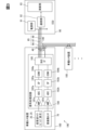
- the object detection system 190 includes a plurality of in-vehicle sensor devices 100 and an ECU 90.
- the details of the electrical configurations of the in-vehicle sensor devices 100 and the ECU 90 will be described based on Fig. 3 with reference to Fig. 2.
- the vehicle-mounted sensor device 100 is connected to the ECU 90 and other vehicle-mounted sensor devices 100 by a plurality of external connection lines 85.
- Each external connection line 85 is formed by a wire harness or the like.
- a connection line (hereinafter, the first connection line) for electrically connecting the sound vibration sensor 70 to the ECU 90 is shared with a connection line (hereinafter, the second connection line) for electrically connecting the ultrasonic microphone 20 to the ECU 90. That is, the external connection line 85 as the first connection line also serves as the second connection line, in other words, the external connection line 85 has the functions of both the first connection line and the second connection line.
- the external connection lines 85 include a power supply line 86, a GND line 87, and a communication line 88.
- the power supply line 86 supplies a power supply voltage to each on-board sensor device 100.
- the GND line 87 supplies a ground voltage to each on-board sensor device 100.
- the communication line 88 forms a communication bus that realizes data communication between the on-board sensor device 100 and the ECU 90.
- a communication bus based on a data communication standard such as LIN, DSI3, or CAN (registered trademark) is used for the communication connection between the on-board sensor device 100 and the ECU 90.
- a communication bus based on a high-speed serial communication standard such as LVDS, Ethernet (registered trademark), or A2B may also be used for the communication connection between the on-board sensor device 100 and the ECU 90.
- a signal processing circuit 180 is provided on the circuit board 80 of the in-vehicle sensor device 100.
- the signal processing circuit 180 is electrically connected to the piezoelectric element 25 of the ultrasonic microphone 20 and the sound detection element (such as the MEMS microphone 170) of the sound vibration sensor 70.
- the signal processing circuit 180 processes the output signals (detection signals) of the ultrasonic microphone 20 and the sound vibration sensor 70, and outputs the respective detection results to the ECU 90.
- the function of the signal processing circuit 180 may be provided by a single dedicated chip such as an ASIC, or may be provided by an electrical circuit formed by combining multiple IC chips.
- the signal processing circuit 180 has amplifiers 181a and 181b, AD converters 182a and 182b, signal processing units 183a and 183b, converters 184a and 184b, and a bus interface 185.
- the amplifier 181a, AD converter 182a, signal processing unit 183a, and converter 184a are connected to the piezoelectric element 25 and are configured to process the output signal of the piezoelectric element 25.
- the converter 184a provides the detection result of the ultrasonic microphone 20 to the bus interface 185.
- the amplifier 181b, AD converter 182b, signal processing unit 183b, and converter 184b are connected to the sound vibration sensor 70 and are configured to process the output signal of the sound vibration sensor 70.
- the converter 184b converts the output signal of the sound vibration sensor 70 into feature information, specifically, spectral information showing the power for each frequency.
- the converter 184b compresses the volume of data transferred to the ECU 90 by converting the output signal into a feature.
- the converter 184b provides the feature (spectral information) to the bus interface 185.
- the bus interface 185 is communicatively connected to the ECU 90 via a communication line 88.
- the bus interface 185 transfers the detection results (sonar results) of the ultrasonic microphone 20 and features (audible sound features) based on the detection results of the sound vibration sensor 70 to the ECU 90 via the communication bus (communication line 88).
- the raw data before conversion to features in other words, the digitally converted uncompressed digital signal, may be transferred from the bus interface 185 to the ECU 90.
- the ECU 90 is an on-board computer installed in the vehicle Ve, and is an external device provided outside the sensor housing 30.
- the ECU 90 may be a dedicated ECU that processes the detection results of the on-board sensor devices 100, or may be an integrated ECU equipped with other functions.
- the ECU 90 is electrically connected to multiple on-board sensor devices 100.
- the ECU 90 includes a power supply unit 91, a communication unit 92, and a calculation unit 93.
- the power supply unit 91 is connected to each vehicle-mounted sensor device 100 via a power supply line 86.
- the power supply unit 91 supplies each vehicle-mounted sensor device 100 with the power supply power required for ultrasonic and audible sound detection operations.
- the communication unit 92 is a bus master, and is connected to each vehicle-mounted sensor device 100 via a communication line 88.
- the communication unit 92 receives the detection results and features transferred by each signal processing circuit 180.
- the communication unit 92 provides the received detection results and features to the calculation unit 93.
- the calculation unit 93 is a processing unit mainly composed of, for example, a microcomputer.
- the calculation unit 93 generates target information such as the relative position, size, and relative speed of targets around the vehicle based on the detection results and features obtained from the communication unit 92.
- the method for mounting the on-vehicle sensor device 100 includes a retainer attachment step, a sensor mounting step, and a connector connection step, in this order.
- the mounting opening 15 is provided in the external structure 10, and then the retainer 60 is attached to the external structure 10.
- the adhesive layer 120 In a configuration in which double-sided tape is used as the adhesive layer 120, one adhesive surface of the adhesive layer 120 is attached to the attachment surface of the retaining portion 62 facing the front side FS. Then, with the center of the retaining space 63 defined on the inner periphery of the surrounding wall 61 aligned with the center of the mounting opening 15, the other adhesive surface of the adhesive layer 120 is attached to the vehicle inner surface 12.
- the retainer 60 is fixed to the external structure 10.
- the sensor housing 30 is mounted to the retainer 60.
- the sensor housing 30 is inserted into the holding space 63 from the back side BS with the transceiver 24 facing the front side FS.
- the sensor housing 30 is fitted into the surrounding wall 61 with the connector connection portion 48 oriented so that it is housed in the cutout portion 61a.
- the transmission/reception surface 24a of the ultrasonic microphone 20 is exposed to the outer space OS from the mounting opening 15 and is generally flush with the vehicle outer surface 11.
- the in-vehicle sensor device 100 is physically fixed to the external structure 10.
- the connector 140 is fitted into the connector connection portion 48.
- a plurality of external connection lines 85 including a power supply line 86, a GND line 87, and a communication line 88 are connected to the connector 140.
- the vehicle-mounted sensor device 100 is electrically connected to the ECU 90 and other vehicle-mounted sensor devices 100.
- the sensor housing 30 for the ultrasonic microphone 20 also houses the sound vibration sensor 70 that detects sound or vibration. Therefore, by mounting the ultrasonic microphone 20 on the vehicle Ve, it is possible to realize mounting the sound vibration sensor 70 on the vehicle Ve.
- the configuration can be simplified compared to the mode in which the sound vibration sensor 70 is configured separately from the ultrasonic microphone 20 and mounted on the vehicle Ve. Therefore, it becomes easier to mount the sound vibration sensor 70 on the vehicle Ve.
- the man-hours required for mounting to the vehicle Ve can be reduced compared to a mode in which the ultrasonic microphone 20 and the sound vibration sensor 70 are mounted separately. As a result, it becomes easy to mount multiple sound vibration sensors 70 on the vehicle Ve.
- the sound vibration sensor 70 is housed in the sensor housing 30 and placed on the back side BS of the external structure 10. Therefore, sound or vibration coming from the outside space OS can be transmitted to the sound vibration sensor 70 through the ultrasonic microphone 20 without passing through the external structure 10 (front bumper, etc.). As a result, the detection of sound or vibration by the sound vibration sensor 70 is less affected by the characteristics of the external structure 10. In other words, by being separated from the external structure 10, the sensor characteristics are less dependent on the vehicle model and grade, etc. As a result, by performing inspection and adjustment at the sensor factory where the vehicle-mounted sensor device 100 is manufactured, it can be easier to guarantee the characteristics of the shipped vehicle-mounted sensor device 100.
- the sound vibration sensor 70 in the first embodiment is arranged separately from the transceiver 24 on the rear side BS of the transceiver 24. In this manner, if the sound vibration sensor 70 is provided separately from the transceiver 24, the characteristics of the sound vibration sensor 70 are less susceptible to the influence of the ultrasonic microphone 20. As a result, it becomes possible to appropriately adjust the characteristics of the sound vibration sensor 70 at a sensor factory, etc.
- an air layer 58 is defined between the sound vibration sensor 70 and the transceiver 24.
- the circuit board 80 is housed in the sensor housing 30, and the sound vibration sensor 70 has a MEMS microphone 170 that is surface-mounted on the circuit board 80.
- the MEMS microphone 170 to be surface-mounted on the circuit board 80, it is possible to omit wiring for electrically connecting the sound vibration sensor 70 and the circuit board 80.
- the configuration of the in-vehicle sensor device 100 can be further simplified.
- the viscoelastic tube 57 which is formed into a cylindrical shape from a viscoelastic material, defines an air layer 58 on the transceiver 24 side (front side FS) of the circuit board 80.
- the deformation of the viscoelastic tube 57 makes it possible to form the air layer 58 between the circuit board 80 and the microphone rear surface 29 while absorbing dimensional variations between them.
- both ends of the viscoelastic tube 57 are pressed against the rear mounting surface 82 of the circuit board 80, it is less likely that the filler will penetrate into the inside of the viscoelastic tube 57 before it hardens.
- a moisture absorbent 59 that absorbs water vapor in the air layer 58 is disposed inside the air layer 58. Therefore, condensation in the air layer 58 caused by temperature changes around the vehicle-mounted sensor device 100 is less likely to occur. As a result, it is also less likely that moisture from condensation will adhere to the sound vibration sensor 70 and gradually change the characteristics of the sound vibration sensor 70.
- the first connection line for electrically connecting the sound vibration sensor 70 to the ECU 90 is shared with the second connection line for electrically connecting the ultrasonic microphone 20 to the ECU 90.
- the external connection line 85 By sharing the external connection line 85 in this way, simplification and cost reduction are possible compared to a configuration in which the first connection line and the second connection line are provided separately.
- the vehicle-mounted sensor device 100 and the ECU 90 are connected via a communication bus, which allows the ultrasonic microphone 20 and the sound vibration sensor 70 to share the communication line 88. Therefore, the configuration for connecting the vehicle-mounted sensor device 100 to the ECU 90 can be further simplified.
- the output signal of the sound vibration sensor 70 is converted into feature information by the converter 184b.
- the feature information is then transferred to the ECU 90.
- data transferred to the ECU 90 can be compressed.
- data can be transferred in real time from the external structure 10 to the ECU 90 without employing a communication bus capable of high-speed communication.
- Such feature information is not limited to the above spectrum and may be changed as appropriate.
- the ultrasonic microphone 20 corresponds to the "ultrasonic sensor”
- the microphone filler 27 corresponds to the "filled covering portion”
- the microphone back surface 29 corresponds to the "rear surface”.
- the air layer 58 corresponds to the "hollow space”
- the circuit board 80 corresponds to the "sensor board”
- the external connection line 85 corresponds to the "first connection line” and the “second connection line”
- the ECU 90 corresponds to the "external device”
- the converter 184b corresponds to the "output conversion portion”.
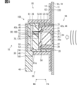
- the in-vehicle sensor device 100 of the second embodiment shown in FIG. 5 is a modified example of the first embodiment.
- the sound vibration sensor 70 is not surface-mounted on the circuit board 80, but is disposed at a position away from the circuit board 80.
- the sound vibration sensor 70 has a configuration including a MEMS microphone 170 or an electret condenser microphone, as in the first embodiment.
- the sound vibration sensor 70 has a sensor lead wire 72.
- the sensor lead wire 72 is an electrical wiring drawn from the main body of the sound vibration sensor 70 to the back side BS, and is embedded in the front filler 54 together with the microphone lead wire 26.
- the sensor lead wire 72 is connected to the front mounting surface 81 by soldering or the like.
- the sound vibration sensor 70 is electrically connected to the circuit board 80 via the sensor lead wire 72.
- the sound vibration sensor 70 is indirectly supported by the housing body 40.
- being indirectly supported by the housing body 40 means being supported by the housing body 40 via a member with a higher elastic modulus than air.
- the sound vibration sensor 70 is attached to the front surface of the front filler 54 facing the front side FS, and the back surface is fixed by the front filler 54.
- the structure equivalent to the intermediate partition wall 42 (see Figure 2) is omitted.
- the air layer 58 is formed in a flat shape between the sound vibration sensor 70 and the back surface of the microphone 29.
- the air layer 58 is partitioned by the sound vibration sensor 70, the back surface of the microphone 29, the damper section 53, and the like.
- the air inside the air layer 58 transmits the audible sound or vibration input to the ultrasonic microphone 20 to the sound vibration sensor 70.
- the second embodiment described so far also has the same effect as the first embodiment, and makes it possible to simplify the configuration for mounting the sound vibration sensor 70 on the vehicle Ve together with the ultrasonic microphone 20. As a result, it becomes easier to mount the sound vibration sensor 70 on the vehicle Ve.
- the sound vibration sensor 70 is indirectly supported by the housing body 40 of the sensor housing 30. With this support structure, the sound vibration sensor 70 can reliably detect sound or vibration transmitted to the air layer 58. As a result, the detection sensitivity of sound or vibration in the audible range can be improved.
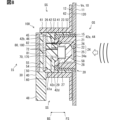
- the on-vehicle sensor device 100 of the third embodiment shown in Fig. 6 is a modified example of the second embodiment.
- the sound vibration sensor 70 of the third embodiment has a piezoelectric element 270 as an audible sound microphone element instead of the MEMS microphone 170 (see Fig. 2).
- the piezoelectric element 270 is bonded to a thin-film metal plate to form a monomorph type diaphragm or a bimorph type diaphragm.
- the piezoelectric element 270 is electrically connected to the circuit board 80 via a sensor lead wire 72.
- the sound vibration sensor 70 is directly supported by the housing body 40.
- the sound vibration sensor 70 is attached to the side of the intermediate partition wall 42 facing the front side FS, and its back side is fixed by the intermediate partition wall 42.
- the sound vibration sensor 70 defines the air layer 58 together with the microphone back side 29 and the damper part 53, and is in contact with the air layer 58.
- the sound vibration sensor 70 detects audible sound or vibration transmitted from the ultrasonic microphone 20 to the air in the air layer 58 using a piezoelectric element 270.
- the third embodiment described so far also has the same effects as the first and second embodiments, and makes it possible to simplify the configuration of mounting the sound vibration sensor 70 together with the ultrasonic microphone 20 on the vehicle Ve.
- the sound vibration sensor 70 is directly supported by the housing body 40 of the sensor housing 30. In this way, with a support structure fixed to a portion of the housing body 40, the sound vibration sensor 70 can reliably detect sound or vibration transmitted to the air layer 58. As a result, the detection sensitivity of sound or vibration in the audible range can be improved.
- the in-vehicle sensor device 100 of the fourth embodiment shown in FIG. 7 is another modified example of the first embodiment.
- the ultrasonic microphone 20 of the fourth embodiment has an accommodating recess 28 formed therein.
- the accommodating recess 28 is formed in the microphone filler 27.
- the accommodating recess 28 is a concave recess formed by recessing the center of the microphone back surface 29 toward the piezoelectric element 25.
- the accommodating recess 28 is formed in a cylindrical hole shape.
- a part of the front side FS of the viscoelastic tube 57 is inserted into the accommodating recess 28.
- the inner peripheral surface of the accommodating recess 28 is fitted onto the viscoelastic tube 57.
- the bottom wall surface of the accommodating recess 28 defines an air layer 58 together with the viscoelastic tube 57.
- the audible sound or vibration input to the ultrasonic microphone 20 is transmitted to the MEMS microphone 170 through the air inside the air layer 58.
- the fourth embodiment described so far also has the same effect as the first embodiment, and makes it possible to simplify the configuration of mounting the sound vibration sensor 70 together with the ultrasonic microphone 20 on the vehicle Ve.
- a concave storage recess 28 that defines at least a portion of the air layer 58 is formed in the microphone filler 27.
- the storage recess 28 corresponds to a "recess.”
- the vehicle-mounted sensor device 100 of the fifth embodiment shown in Fig. 8 is a modified example of the fourth embodiment.
- the housing body 40 of the fifth embodiment is provided with a microphone holding protrusion 42d.
- the microphone holding protrusion 42d is formed on the intermediate partition wall 42.
- the microphone holding protrusion 42d stands upright from the inner edge of the intermediate partition wall 42 facing the connection opening 42c toward the front side FS.
- the sound vibration sensor 70 is attached to the top surface of the microphone holding protrusion 42d facing the front side FS, and is fixed to the microphone holding protrusion 42d.
- the sound vibration sensor 70 is electrically connected to the circuit board 80 via a sensor lead wire 72.
- Most of the sound vibration sensor 70 is housed in the accommodation recess 28 provided in the ultrasonic microphone 20.
- An air layer 58 is defined between the sound vibration sensor 70 and the inner circumferential surface and bottom wall surface of the accommodation recess 28.
- the sound vibration sensor 70 measures the sound or vibration in the hearing range that is transmitted through the air in the air layer 58 inside the accommodation recess 28.
- the fifth embodiment described so far also has the same effect as the fourth embodiment, and allows for a simplified configuration in which the sound vibration sensor 70 is mounted on the vehicle Ve together with the ultrasonic microphone 20.
- a configuration in which the ultrasonic microphone 20 has a storage recess 28 formed therein and the sound vibration sensor 70 is stored in the storage recess 28 allows for a thinner in-vehicle sensor device 100.
- the vehicle-mounted sensor device 100 of the sixth embodiment shown in Fig. 9 is a modified example of the fifth embodiment.
- the configuration corresponding to the microphone holding protrusion 42d (see Fig. 8) is omitted.
- the sound vibration sensor 70 is supported by the inner edge of the side surface of the intermediate partition wall 42 facing the front side FS, which faces the connection opening 42c.
- the sound vibration sensor 70 is accommodated in the accommodation recess 28 provided in the ultrasonic microphone 20.
- An air layer 58 is defined between the sound vibration sensor 70 and the bottom wall surface of the accommodation recess 28.
- the ultrasonic microphone 20 has a housing recess 28 formed therein, and the sound vibration sensor 70 is housed in the housing recess 28. This makes it possible to reduce the thickness of the vehicle-mounted sensor device 100.
- the on-vehicle sensor device 100 of the seventh embodiment shown in FIG. 10 is yet another modified example of the first embodiment.
- the sound vibration sensor 70 of the seventh embodiment has a monomorph type diaphragm or bimorph type diaphragm including a piezoelectric element 270, or a plate-thickness type piezoelectric element, as in the third embodiment.
- the sound vibration sensor 70 is attached to the microphone back surface 29 by a sensor adhesive layer 74.
- the sensor adhesive layer 74 is formed of a double-sided tape, an adhesive material, or the like. The sound vibration sensor 70 is held on the microphone back surface 29 via the sensor adhesive layer 74.
- the back surface of the sound vibration sensor 70 is directly supported by the housing body 40.
- the sound vibration sensor 70 is held on the inner edge of the side surface of the intermediate partition wall 42 facing the front side FS, which faces the connection opening 42c.
- the sound vibration sensor 70 detects audible sounds or vibrations transmitted from the ultrasonic microphone 20 using a piezoelectric element 270.
- the seventh embodiment described so far also has the same effect as the first embodiment, and makes it possible to simplify the configuration of mounting the sound vibration sensor 70 together with the ultrasonic microphone 20 on the vehicle Ve.
- the sound vibration sensor 70 is held by the microphone back surface 29 of the ultrasonic microphone 20.
- the air layer 58 (see FIG. 2) can be omitted, and the configuration of the vehicle-mounted sensor device 100 can be simplified.
- the sound vibration sensor 70 is held on the microphone back surface 29 via a sensor adhesive layer 74.
- a sensor adhesive layer 74 With this configuration, sound or vibration input to the ultrasonic microphone 20 is easily transmitted to the ultrasonic microphone 20. As a result, it is possible to ensure the detection sensitivity of the sound vibration sensor 70.
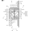
- the vehicle-mounted sensor device 100 of the eighth embodiment shown in FIG. 11 is a modified example of the seventh embodiment.
- the sound vibration sensor 70 of the eighth embodiment has a monomorph type diaphragm or a bimorph type diaphragm formed by bonding a piezoelectric element 270 and a metal plate 73, as in the seventh embodiment.
- the sound collection surface on the front side FS of the sound vibration sensor 70 is held on the microphone back surface 29 via a sensor adhesive layer 74.
- the holding surface on the back side BS of the sound vibration sensor 70 is attached to the front surface of the front filler 54 and fixed to the front filler 54.
- the sound vibration sensor 70 is indirectly supported by the housing body 40 via the front filler 54.
- the sound vibration sensor 70 detects audible sound or vibration transmitted from the ultrasonic microphone 20 to the metal plate 73 by the piezoelectric element 270.
- the eighth embodiment described so far also has the same effect as the seventh embodiment, and allows for a simplified configuration in which the sound vibration sensor 70 is mounted on the vehicle Ve together with the ultrasonic microphone 20.
- the sound vibration sensor 70 is held by the microphone back surface 29 of the ultrasonic microphone 20, the configuration of the in-vehicle sensor device 100 can be simplified.
- the on-vehicle sensor device 100 of the ninth embodiment shown in Fig. 12 is another modified example of the seventh embodiment.
- a vibration transmission unit 75 is provided between the microphone back surface 29 and a metal plate 73.
- the vibration transmission unit 75 is formed in a flat plate shape using a material having a higher elastic modulus than the damper unit 53, such as a metal material (e.g., aluminum) or a resin material.
- the damper unit 53 may be formed in a partial cone shape or a partial pyramid shape whose longitudinal section is a trapezoidal shape.
- Both sides of the vibration transmission unit 75 are pressed firmly against the microphone back surface 29 and the metal plate 73, respectively, and are tightly attached to the microphone back surface 29 and the metal plate 73 with no gaps.
- the vibration transmission unit 75 is in contact only with the center part of the front surface of the sound vibration sensor 70.
- the vibration transmission unit 75 transmits the sound or vibration input to the ultrasonic microphone 20 to the metal plate 73.
- the ninth embodiment described so far also has the same effect as the seventh embodiment, and allows for a simplified configuration in which the sound vibration sensor 70 is mounted on the vehicle Ve together with the ultrasonic microphone 20.
- the detection sensitivity of the sound vibration sensor 70 can be improved by the configuration in which the vibration transmission unit 75 transmits vibrations from the ultrasonic microphone 20 to the sound vibration sensor 70.
- the tenth embodiment of the in-vehicle sensor device 100 shown in Figure 13 is a modified example of the ninth embodiment.
- the ultrasonic microphone 20 of the tenth embodiment has a vibration transmission part 75.
- the vibration transmission part 75 is formed by a microphone filler 27.
- the vibration transmission part 75 is a convex part that protrudes to the back side BS, and is provided in the center of the microphone back surface 29.
- the top of the vibration transmission part 75 is pressed against the center of the metal plate 73. Sound or vibration input to the ultrasonic microphone 20 is transmitted to the metal plate 73 by the vibration transmission part 75.
- the tenth embodiment described so far also has the same effect as the ninth embodiment, and allows for a simplified configuration in which the sound vibration sensor 70 is mounted on the vehicle Ve together with the ultrasonic microphone 20.
- the detection sensitivity of the sound vibration sensor 70 can be improved by the configuration in which the vibration transmission unit 75 provided on the back surface 29 of the microphone transmits vibrations to the sound vibration sensor 70.
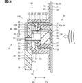
- the on-vehicle sensor device 100 of the eleventh embodiment shown in FIG. 14 is yet another modified example of the first embodiment.
- the on-vehicle sensor device 100 is provided with a rear sound guide tube 157.
- the rear sound guide tube 157 is formed integrally with the viscoelastic tube 57.
- the rear sound guide tube 157 is formed in a cylindrical shape.
- the rear sound guide tube 157 penetrates the circuit board 80 in the plate thickness direction, and defines a cylindrical rear sound guide space 157a extending from the air layer 58 to the rear side BS.
- the end of the rear side BS of the rear sound guide tube 157 is fitted into the sound guide recess 51 provided in the rear cover 50.
- the sound guide recess 51 forms a thin plate portion in the rear cover 50.
- the sound vibration sensor 70 can detect sound or vibrations in the inner space IS (e.g., engine sound, motor sound, etc.) in addition to sound or vibrations in the outer space OS.
- the eleventh embodiment described so far also has the same effect as the first embodiment, and makes it possible to simplify the configuration of mounting the sound vibration sensor 70 together with the ultrasonic microphone 20 on the vehicle Ve.
- the vehicle-mounted sensor device 100 is equipped with a cylindrical rear sound guide tube 157.
- the rear sound guide tube 157 introduces sound or vibration from the inner space IS located on the rear side BS of the housing main body 40 to the air layer 58.
- the rear sound guide tube 157 corresponds to the "sound guide tube portion.”
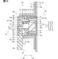
- the in-vehicle sensor device 100 of the twelfth embodiment shown in Fig. 15 is a modified example of the eleventh embodiment.
- the rear cover 50 of the twelfth embodiment is formed with a sound guide opening 51a instead of the sound guide recess 51 (see Fig. 14).
- the sound guide opening 51a is a through hole penetrating the rear cover 50 in the plate thickness direction.
- the end of the rear sound guide tube 157 is fitted into the sound guide opening 51a.
- the sound guide opening 51a and the rear sound guide space 157a are blocked from the rear side BS by the sound guide film 51b.
- the sound guide film 51b is formed in a thin film shape from a material (e.g. Gore-Tex, registered trademark) that is waterproof and allows sound and vibration to pass through.
- the twelfth embodiment described so far also has the same effect as the eleventh embodiment, and allows for a simplified configuration in which the sound vibration sensor 70 is mounted on the vehicle Ve together with the ultrasonic microphone 20.
- sound or vibration generated in the inner space IS is transmitted from the sound guide membrane 51b and the rear sound guide space 157a to the air layer 58.
- the vehicle-mounted sensor device 100 of the thirteenth embodiment shown in FIG. 16 is another modified example of the eleventh embodiment.
- the vehicle-mounted sensor device 100 is provided with a side sound guide tube 158.
- the side sound guide tube 158 is formed integrally with the viscoelastic tube 57.
- the side sound guide tube 158 is formed in a cylindrical shape.
- the side sound guide tube 158 defines a cylindrical side sound guide space 158a extending from the air layer 58 toward the housing peripheral wall 41.
- the end of the side sound guide tube 158 opposite to the air layer 58 is fitted into the sound guide opening 41a provided in the housing peripheral wall 41.
- the sound guide opening 41a and the side sound guide space 158a are blocked from the outer periphery by the sound guide membrane 41b.
- the sound guide membrane 41b is formed of a material that transmits sound and vibrations, similar to the sound guide membrane 51b of the twelfth embodiment (see FIG. 15).
- the thirteenth embodiment described so far also has the same effect as the eleventh embodiment, and makes it possible to simplify the configuration of mounting the sound vibration sensor 70 together with the ultrasonic microphone 20 on the vehicle Ve.
- the vehicle-mounted sensor device 100 is equipped with a cylindrical side sound guide tube 158.
- the side sound guide tube 158 introduces sound or vibration from the side space SS located on the side of the housing main body 40 to the air layer 58. As a result, it is possible to detect sound or vibration in the side space SS without increasing the number of sound vibration sensors 70 provided in the vehicle-mounted sensor device 100.
- the side sound guide tube 158 corresponds to the "sound guide tube portion.”
- the vehicle-mounted sensor device 100 of the fourteenth embodiment shown in Fig. 17 is another modified example of the second embodiment.
- a moisture absorbent 59 is provided in the air layer 58 of the vehicle-mounted sensor device 100.
- the moisture absorbent 59 is formed in a chip shape and is attached to the microphone back surface 29.
- the moisture absorbent 59 absorbs water vapor generated in the air layer 58 and suppresses the occurrence of condensation in the air layer 58.
- the vehicle-mounted sensor device 100 of the fifteenth embodiment shown in Fig. 18 is yet another modified example of the first embodiment.
- the moisture absorbent 59 is omitted. In this manner, the presence or absence of the moisture absorbent 59 may be changed as appropriate.
- the vehicle-mounted sensor device 200 of the sixteenth embodiment shown in Fig. 19 is yet another modified example of the first embodiment.
- the transceiver 24 is shared with the sound vibration sensor 70.
- the piezoelectric element 25 constituting the transceiver 24 detects ultrasonic waves as well as sounds and vibrations in the audible range, thereby also serving as the sound vibration sensor 70.
- the ultrasonic microphone 20 and the housing body 40 provided in the vehicle-mounted sensor device 200 of the sixteenth embodiment will be described in detail below.
- the ultrasonic microphone 20 has a compartment housing 221 and a vibration membrane 222.
- the compartment housing 221 is formed into a cylindrical shape with a bottom, from a metal material such as aluminum or a resin material such as silicone rubber.
- the compartment housing 221 is accommodated inside the microphone housing 21 with its bottom wall, which is formed into a thin plate, facing the back side BS.
- the microphone internal space 220 is located on the back side BS of the piezoelectric element 25, and is a sealed, airtight hollow space facing the piezoelectric element 25.
- the back side of the piezoelectric element 25 is exposed in the microphone internal space 220.
- the piezoelectric element 25 can detect pressure fluctuations occurring in the microphone internal space 220 in addition to vibrations occurring in the receiving bottom 22.
- the diaphragm 222 is formed in the center of the microphone back surface 29.
- a hollow microphone internal space 220 is provided inside the microphone filler 27, allowing the diaphragm 222 to elastically deform in the film thickness direction. When the diaphragm 222 deforms in the film thickness direction, a pressure fluctuation occurs in the microphone internal space 220.
- the housing body 40 supports the ultrasonic microphone 20 in a state that allows displacement due to audible sound or vibration, as in the first embodiment.
- the ultrasonic microphone 20 can be slightly displaced along the axial direction of the housing peripheral wall 41 due to elastic support via the cushion portion 52 and the damper portion 53.
- the housing body 40 is provided with a compression portion 240 that compresses the microphone internal space 220 due to displacement of the ultrasonic microphone 20.
- the compression section 240 is formed by a compression protrusion 241.
- the compression protrusion 241 is formed in the center of one of the two side surfaces of the intermediate partition wall 42 that faces the front side FS.
- the compression protrusion 241 protrudes from the intermediate partition wall 42 to the front side FS, and the top surface of the compression protrusion 241 abuts against the vibration membrane 222.
- the compression protrusion 241 serves as a pressing surface 248 that directly presses against the vibration membrane 222.
- the vibration membrane 222 in contact with the pressing surface 248 vibrates. This causes a pressure fluctuation in the microphone internal space 220, and the piezoelectric element 25 can measure the audible sound or vibration by detecting the generated pressure fluctuation.
- the sixteenth embodiment described so far also has the same effect as the first embodiment, and makes it possible to simplify the configuration of mounting the sound vibration sensor 70 together with the ultrasonic microphone 20 on the vehicle Ve.
- a microphone internal space 220 is defined on the rear side BS of the transceiver 24, facing the transceiver 24.
- the sensor housing 30 supports the ultrasonic microphone 20 in a state that allows displacement due to audible sound or vibration.
- a compression section 240 is provided inside the sensor housing 30, that compresses the microphone internal space 220 due to displacement of the ultrasonic microphone 20.
- the piezoelectric element 25 of the transceiver 24 is shared with the sound vibration sensor 70. As described above, the piezoelectric element 25 also serves the function of the sound vibration sensor 70, which makes it possible to further simplify the configuration of the vehicle-mounted sensor device 200.
- the microphone internal space 220 corresponds to a "hollow space".
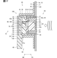
- the vehicle-mounted sensor device 200 of the seventeenth embodiment shown in Fig. 20 is a modified example of the sixteenth embodiment.
- a configuration corresponding to the vibration membrane 222 (see Fig. 19) is omitted.
- the microphone internal space 220 is partitioned as a generally airtight space by the partition housing 221, the damper portion 53, the compression piston portion 242, etc.
- the compression piston portion 242 has a structure equivalent to the compression protrusion 241 (see FIG. 19).
- the compression piston portion 242 is formed into a cylindrical or rectangular column shape from a metal or resin material.
- the compression piston portion 242 is fixed to the center of one of the two side surfaces of the intermediate partition wall 42 that faces the front side FS. Most of the compression piston portion 242 is housed in the microphone internal space 220.
- the top surface (pressure surface 248) of the compression piston portion 242 that faces the front side FS faces the back surface of the piezoelectric element 25.
- the outer surface of the compression piston portion 242 faces the inner surface of the partition housing 221 with a small gap therebetween.
- the ultrasonic microphone 20 when the ultrasonic microphone 20 is displaced due to audible sound or vibration input to the ultrasonic microphone 20, the distance between the pressing surface 248 and the piezoelectric element 25 increases or decreases. This causes pressure fluctuations in the microphone internal space 220, and the piezoelectric element 25 can measure audible sound or vibrations by detecting the pressure fluctuations that occur in the microphone internal space 220.
- the seventeenth embodiment described so far also has the same effect as the sixteenth embodiment, and allows for a simplified configuration in which the sound vibration sensor 70 is mounted on the vehicle Ve together with the ultrasonic microphone 20.
- the piezoelectric element 25 also serves the function of the sound vibration sensor 70, so the configuration of the vehicle-mounted sensor device 200 can be further simplified.
- the vehicle-mounted sensor device 200 of the eighteenth embodiment shown in Fig. 21 is a modified example of the seventeenth embodiment.
- the compression piston portion 242 of the eighteenth embodiment is provided slidably relative to the partition housing 221.
- the microphone internal space 220 is partitioned as a generally airtight space by the partition housing 221, the compression piston portion 242, etc.
- the compression piston portion 242 is held in the intermediate partition wall 42 via a bush 243.
- the bush 243 is formed in a thin plate shape from silicone rubber or the like.
- the eighteenth embodiment described so far also has the same effect as the seventeenth embodiment, and allows for a simplified configuration in which the sound vibration sensor 70 is mounted on the vehicle Ve together with the ultrasonic microphone 20.
- the piezoelectric element 25 also serves the function of the sound vibration sensor 70, so the configuration of the vehicle-mounted sensor device 200 can be further simplified.
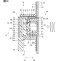
- the on-vehicle sensor device 200 of the 19th embodiment shown in Fig. 22 is another modified example of the 17th embodiment.
- the compression piston portion 242 of the 19th embodiment has a contact point 244.
- the contact point 244 is formed in a plate shape using rubber, double-sided tape, or the like.
- the contact point 244 is attached to the tip of the compression piston portion 242 protruding from the intermediate partition wall 42 to the front side FS.
- the compression piston portion 242 is indirectly in contact with the back surface of the piezoelectric element 25 via the contact point 244.
- the compression piston portion 242 has its rear side BS directly fixed by the intermediate partition wall 42. Most of the front side FS of the compression piston portion 242 is housed in the microphone internal space 220.
- the microphone internal space 220 is a space that is open to the rear side BS.
- the compression piston portion 242 is inserted into the microphone internal space 220 through an opening formed in the bottom wall of the partition housing 221.
- the piezoelectric element 25 is able to measure the audible sound or vibration by detecting the vibration input by the contact point 244.
- the nineteenth embodiment described so far also has the same effect as the seventeenth embodiment, and allows for a simplified configuration in which the sound vibration sensor 70 is mounted on the vehicle Ve together with the ultrasonic microphone 20.
- the piezoelectric element 25 also serves the function of the sound vibration sensor 70, so the configuration of the vehicle-mounted sensor device 200 can be further simplified.
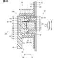
- the in-vehicle sensor device 200 of the twentieth embodiment shown in FIG. 23 is a modified example of the nineteenth embodiment.
- the compression piston portion 242 is indirectly held by the intermediate partition wall 42.
- the back surface of the compression piston portion 242 is fixed relatively to the center of the intermediate partition wall 42 via a bush 243.
- the bush 243 is formed in a plate shape using rubber or double-sided tape or the like.
- the compression piston portion 242 has a pressing surface 248 facing the front side FS in direct contact with the back surface of the piezoelectric element 25.
- the compression piston portion 242 presses the piezoelectric element 25 with the pressing surface 248.
- the piezoelectric element 25 can measure audible sound or vibration.
- the twentieth embodiment described so far also has the same effect as the nineteenth embodiment, and allows for a simplified configuration in which the sound vibration sensor 70 is mounted on the vehicle Ve together with the ultrasonic microphone 20.
- the piezoelectric element 25 also serves the function of the sound vibration sensor 70, so the configuration of the vehicle-mounted sensor device 200 can be further simplified.
- the twenty-first embodiment of the in-vehicle sensor device 300 shown in Fig. 24 is yet another modified example of the first embodiment.
- the sensor housing 30 of the in-vehicle sensor device 300 includes a sub-housing 340 in addition to the housing main body 40, rear cover 50, and retainer 60.
- the sub-housing 340 is provided on the rear side BS of the holding portion 62 of the retainer 60.
- the sub-housing 340 houses a sound vibration sensor 70 and a sub-substrate 380.
- the sound vibration sensor 70 is electrically connected to the sub-substrate 380 by a sensor lead wire 72.
- the in-vehicle sensor device 300 also has the same effect as the first embodiment, and enables the configuration of mounting the sound vibration sensor 70 on the vehicle Ve together with the ultrasonic microphone 20 to be simplified.
- the audible microphone element of the sound vibration sensor 70 housed in the sub-housing 340 may be appropriately changed to a MEMS microphone 170 audible microphone element, an electret condenser microphone, a piezoelectric element 270, etc.
- the transceiver 24 is configured to both receive and transmit ultrasonic waves. Such a transceiver 24 may be configured to only receive or transmit ultrasonic waves. Furthermore, the sound vibration sensor 70 may be configured to only detect either sound or vibration in the audible range.
- the sensor housing 30 does not need to have a retainer 60.
- a structure equivalent to the holding portion 62 is provided in the housing body 40.
- the housing body 40 is directly fixed to the vehicle inner surface 12 by the holding portion 62 and the adhesive layer 120.
- the vehicle Ve equipped with the on-board sensor device 100 is not limited to a general private passenger car, but may be a rental car vehicle, a manned taxi vehicle, a ride-sharing vehicle, a freight vehicle, a bus, etc. Furthermore, the on-board sensor device 100 can be installed in a vehicle dedicated to unmanned driving used for mobility services. In addition, the number and installation positions of the on-board sensor devices 100 are appropriately optimized according to the type of the vehicle Ve, the purpose of the vehicle Ve, and the traffic environment and laws and regulations of the country or region in which the vehicle Ve is used.
- each function provided by the signal processing circuit 180 and ECU 90 can also be provided by software and hardware that executes it, software alone, hardware alone, or a combination of these. Furthermore, when such functions are provided by electronic circuits as hardware, each function can also be provided by digital circuits including multiple logic circuits, or analog circuits.
- (Technical Concept 1) An on-board sensor device mounted on a vehicle (Ve), An ultrasonic sensor (20) having a transceiver (24) for receiving and/or transmitting ultrasonic waves; A sensor housing (30) that accommodates at least a portion of the ultrasonic sensor; An on-vehicle sensor device comprising: a sound vibration sensor (70) housed in the sensor housing together with the ultrasonic sensor and configured to detect sounds or vibrations in the audible range.
- (Technical Concept 2) The vehicle-mounted sensor device according to Technical Idea 1, wherein the sound vibration sensor is arranged separately from the transceiver on the rear side (BS) of the transceiver.
- the in-vehicle sensor device according to Technical Idea 2 wherein the sensor housing defines a hollow space (58) between the sound vibration sensor and the transmitter/receiver.
- the vehicle-mounted sensor device described in Technical Idea 4 further includes a viscoelastic tube (57) formed in a cylindrical shape from a viscoelastic material and partitioning the hollow space on the transmitter/receiver side of the sensor board.
- the ultrasonic sensor further includes a filling covering portion (27) that covers the transmitter/receiver from the rear side, The vehicle-mounted sensor device according to any one of technical ideas 3 to 5, wherein the filling covering portion is formed with a concave recess portion (28) that defines at least a portion of the hollow space.
- (Technical Concept 8) An on-vehicle sensor device as described in any one of technical ideas 3 to 7, further comprising a cylindrical sound-guiding tube portion (157, 158) that introduces sound or vibration into the hollow space from at least one of an inner space (IS) located on the rear side of the sensor housing or a lateral space (SS) located on the side of the sensor housing.
- (Technical Concept 10) The in-vehicle sensor device according to Technical Idea 9, wherein the sound vibration sensor is held on the back side via a sensor adhesive layer (74).
- the ultrasonic sensor defines a hollow space (220) facing the transceiver on the rear side of the transceiver, the sensor housing supports the ultrasonic sensor in a state in which the ultrasonic sensor is allowed to be displaced by sound or vibration in the audible range;
- a compression section (240) is provided inside the sensor housing to compress the hollow space by displacement of the ultrasonic sensor,
- the vehicle-mounted sensor device according to Technical Idea 1, wherein the transmitter/receiver is shared with the sound vibration sensor.
- An in-vehicle sensor device comprising:
Landscapes
- Engineering & Computer Science (AREA)
- Radar, Positioning & Navigation (AREA)
- Remote Sensing (AREA)
- Physics & Mathematics (AREA)
- Computer Networks & Wireless Communication (AREA)
- General Physics & Mathematics (AREA)
- Acoustics & Sound (AREA)
- Measurement Of Velocity Or Position Using Acoustic Or Ultrasonic Waves (AREA)
Abstract
車載センサ装置(100)は、車両(Ve)に搭載され、超音波マイク(20)、センサ筐体(30)、及び音振動センサ(70)を備えている。超音波マイク(20)は、超音波の受信及び送信の少なくとも一方を行う送受信器(24)を有している。センサ筐体(30)は、超音波マイク(20)の少なくとも一部を収容している。音振動センサ(70)は、超音波マイク(20)と共にセンサ筐体(30)に収容されており、可聴域の音又は振動を検出する。
Description
この出願は、2023年6月12日に日本に出願された特許出願第2023-96457号を基礎としており、基礎の出願の内容を、全体的に、参照により援用している。
この明細書における開示は、車両に搭載される車載センサ装置に関する。
特許文献1には、車両に搭載されるトランスデューサアレイが記載されている。このトランスデューサアレイは、超音波等の音響信号を送受信することにより、周囲の物体と車両との間の距離の計測を可能にする。
音響信号には、特許文献1に開示のような超音波だけでなく、可聴域の音及び振動が存在する。こうした可聴域の音又は振動を検出する音振動センサを車載することが検討されつつある。しかし、特許文献1のような超音波センサとは別に、音振動センサを車両に搭載する場合、構成の複雑化によって搭載の難易度が高くなることがあった。
本開示は、音振動センサの車両への搭載を容易にすることが可能な車載センサ装置の提供を目的とする。
上記目的を達成するため、開示された一つの態様は、車両に搭載される車載センサ装置であって、超音波の受信及び送信の少なくとも一方を行う送受信器を有する超音波センサと、超音波センサの少なくとも一部を収容するセンサ筐体と、超音波センサと共にセンサ筐体に収容され、可聴域の音又は振動を検出する音振動センサと、を備える車載センサ装置とされる。
この態様では、超音波センサのためのセンサ筐体に、音又は振動を検出する音振動センサも収容されている。故に、超音波センサの車両への搭載により、音振動センサの車両への搭載も実現され得る。以上によれば、音振動センサを超音波センサから独立させた構成として車両に搭載する態様よりも簡素化が可能になる。したがって、音振動センサの車両への搭載が容易になる。
尚、請求の範囲における括弧内の参照番号は、後述する実施形態における具体的な構成との対応関係の一例を示すものにすぎず、技術的範囲を何ら制限するものではない。また、特に組み合わせに支障が生じなければ、請求の範囲において明示していない請求項同士の組み合せも可能である。
以下、複数の実施形態を図面に基づいて説明する。尚、各実施形態において対応する構成要素には同一の符号を付すことにより、重複する説明を省略する場合がある。各実施形態において構成の一部分のみを説明している場合、当該構成の他の部分については、先行して説明した他の実施形態の構成を適用することができる。また、各実施形態の説明において明示している構成の組み合わせばかりではなく、特に組み合わせに支障が生じなければ、明示していなくても複数の実施形態の構成同士を部分的に組み合せることができる。
[音響センサ装置の取り付け位置]
本開示による車載センサ装置100は、図1及び図2に示すように、車両Veに搭載される。車載センサ装置100は、車両前面、車両側面、及び車両後面等、車両Veの種々の箇所に設定可能である。車載センサ装置100は、板状を呈する車両Veの外部構造部10に、超音波の送受信面24aを外表面側に露出させた状態で保持される。
本開示による車載センサ装置100は、図1及び図2に示すように、車両Veに搭載される。車載センサ装置100は、車両前面、車両側面、及び車両後面等、車両Veの種々の箇所に設定可能である。車載センサ装置100は、板状を呈する車両Veの外部構造部10に、超音波の送受信面24aを外表面側に露出させた状態で保持される。
車両前面の外部構造部10は、例えば、フロントバンパ中央部Pf1及びフロントバンパコーナー部Pf2等である。車両前面の外部構造部10に設置された車載センサ装置100は、送受信面24aを車両Veの前方Zeに向けた姿勢となり、車両Veの外部のうちで主に前方Zeの物標の検出に用いられる。
車両側面の外部構造部10は、例えば、フロントバンパサイド部Ps1、リヤバンパサイド部Ps2、サイドミラーカバーPs3、及びサイドステップPs4等である。車両側面の外部構造部10に設置された車載センサ装置100は、送受信面24aを車両Veの右方Mi又は左方Hiに向けた姿勢となり、車両Veの外部のうちで主に側方の物標の検出に用いられる。
車両後面の外部構造部10は、例えば、リヤバンパ中央部Pb1及びリヤバンパコーナー部Pb2等である。車両後面の外部構造部10に設置された車載センサ装置100は、送受信面24aを車両Veの後方Goに向けた姿勢となり、車両Veの外部のうちで主に後方Goの物標の検出に用いられる。
ここで、本開示における前後方向及び左右方向は、水平面上に静止させた車両Veを基準として規定される。具体的に、前後方向(前方Ze及び後方Go)は、車両Veの長手方向(進行方向)に沿って規定される。また左右方向(右方Mi及び左方Hi)は、車両Veの幅方向に沿って規定される。さらに、上下方向(上方Ue)は、前後方向及び左右方向を規定した水平面の鉛直方向に沿って規定される。尚、記載の簡略化のため、以下の説明では、各方向を示す符号の記載を適宜省略する場合がある。
(第一実施形態)
図2に示す本開示の第一実施形態による車載センサ装置100は、超音波の受信及び送信を行う超音波マイク20と、可聴域の音又は振動を検出する音振動センサ70とを備えている。超音波は、人間の耳には聞こえない高い振動数をもつ音波であり、具体的には、20kHz以上の音波である。可聴域は、超音波よりも低い周波数帯域であり、具体的には、20Hzから20kHzまでの領域である。車載センサ装置100は、外部構造部10及び接着層120と共に、車載センサ設置構造を構成している。
図2に示す本開示の第一実施形態による車載センサ装置100は、超音波の受信及び送信を行う超音波マイク20と、可聴域の音又は振動を検出する音振動センサ70とを備えている。超音波は、人間の耳には聞こえない高い振動数をもつ音波であり、具体的には、20kHz以上の音波である。可聴域は、超音波よりも低い周波数帯域であり、具体的には、20Hzから20kHzまでの領域である。車載センサ装置100は、外部構造部10及び接着層120と共に、車載センサ設置構造を構成している。
外部構造部10は、例えばフロントバンパ又はリヤバンパ等であり、ポリプロピレン等の樹脂材料によって平板状又は僅かに湾曲した板状に形成されている。外部構造部10は、車両Veの前方Ze、後方Go、又は側方を向く姿勢で、車両Veの外部に露出する車両外表面11を有している。外部構造部10において、車両外表面11の裏側は、接着層120が取り付けられる平滑な車両内側面12となっている。外部構造部10には、取付開口15が形成されている。取付開口15は、外部構造部10を板厚方向に貫通する扁平な貫通穴である。取付開口15は、車載センサ装置100の送受信面24aを車両外表面11側に露出させる。
接着層120は、両面テープ又は接着材等によって形成されている。接着層120は、外部構造部10よりも薄い薄膜状に形成されている。接着層120の各面は、車両内側面12及び車載センサ装置100のそれぞれに接合されている。接着層120により、車載センサ装置100は、車両内側面12に対して固定されている。
尚、以下の説明では、車両外表面11及び送受信面24aの向く方向を正面側FSとし、車両内側面12の向く方向を背面側BSとする。また、外部構造部10よりも正面側FSの空間を外側空間OSとし、車載センサ装置100の背面(背面カバー50)よりも背面側BSの空間を内側空間ISとし、車載センサ装置100の周囲の空間を側方空間SSとする。外側空間OSは、超音波及び可聴音の到来する車外空間である。内側空間ISは、車両Veの内側となる空間である。側方空間SSは、車両内側面12に沿って車載センサ装置100の上下左右に位置する空間である。
[車載センサ装置の構成]
車載センサ装置100は、超音波マイク20、センサ筐体30、音振動センサ70、及び回路基板80等によって構成されている。
車載センサ装置100は、超音波マイク20、センサ筐体30、音振動センサ70、及び回路基板80等によって構成されている。
超音波マイク20は、超音波を送受信可能に構成されている。超音波マイク20は、超音波である探査波を外側空間OSに向けて発信する。超音波マイク20は、外側空間OSに存在する物体によって反射された探査波(反射波)を受信し、反射波の受信結果に応じた検出信号を出力する。超音波マイク20は、マイクハウジング21、圧電素子25、及びマイク充填剤27を備えている。
マイクハウジング21は、アルミニウム等の金属材料によって有底の円筒状に形成されている。マイクハウジング21は、受信底部22及び側壁部23を有している。受信底部22は、マイクハウジング21の底部に薄板状に形成されている。受信底部22の内側面には、圧電素子25が固定されている。受信底部22は、ダイヤフラムとして機能し、超音波の受信及び送信の少なくとも一方を行う送受信器24を、圧電素子25と共に構成している。受信底部22の外側面は、車載センサ装置100の外部構造部10への取り付けにより、外側空間OSに露出する送受信面24aとなる。側壁部23は、受信底部22の周囲を囲む円筒状に形成されている。
圧電素子25は、薄膜状に形成されている。圧電素子25は、受信底部22及び側壁部23によって区画された(囲まれた)マイクハウジング21の内部空間に収容されている。圧電素子25は、マイク引出線26を介して回路基板80に電気的に接続されている。圧電素子25は、入力される電気信号に基づき微小な振動を発生させ、送受信器24からの超音波(探査波)の発信を可能にする。圧電素子25は、送受信器24に到来する超音波(反射波)の振動を電気信号に変換することで、反射波の検出を可能にする。
マイク充填剤27は、マイクハウジング21の内部空間に充填され、内部空間内で硬化したシリコーンゴム又は発泡ウレタン等によって形成されている。マイク充填剤27は、送受信器24を背面側BSから覆っており、圧電素子25を封止している。マイク充填剤27は、側壁部23の背面側BSの端面と共に超音波マイク20の背面(以下、マイク背面29)を形成している。
センサ筐体30は、超音波センサ、音振動センサ70、及び回路基板80等を収容する収容構成である。センサ筐体30は、筐体本体40、背面カバー50、及びリテーナ60等によって構成されている。
筐体本体40は、ポリブチレンテレフタレート(PBT)等の樹脂材料によって箱状に形成されている。筐体本体40には、筐体周壁41、中間区画壁42、及びコネクタ接続部48が形成されている。
筐体周壁41は、筒状に形成されている。筐体周壁41は、マイク支持部44、カバー固定部45、及び基板固定部46を有している。マイク支持部44は、筐体周壁41のうちで中間区画壁42よりも正面側FSの部分の内周面に形成されている。マイク支持部44は、クッション部52(後述する)を介して超音波マイク20を支持している。カバー固定部45は、筐体周壁41のうちで背面側BSの端部の内周面に形成されている。カバー固定部45は、背面カバー50を保持している。基板固定部46は、筐体周壁41の内周面に形成された段差面部である。基板固定部46は、背面側BSを向く姿勢で、カバー固定部45と中間区画壁42との間に形成されている。基板固定部46は、回路基板80を正面側FSから支持している。
中間区画壁42は、筐体周壁41の内周面から、筐体周壁41の内周側へ向けて立設されている。中間区画壁42は、筐体本体40の内部空間を、マイク収容室42aと基板収容室42bとに区分けしている。マイク収容室42aは、中間区画壁42の正面側FSに区画されている。マイク収容室42aには、超音波マイク20の少なくとも一部が収容されている。基板収容室42bは、中間区画壁42の背面側BSに区画されている。基板収容室42bには、回路基板80及び背面カバー50が収容されている。中間区画壁42には、接続開口42cがさらに形成されている。接続開口42cは、中間区画壁42を板厚方向に貫通する扁平な貫通孔である。接続開口42cは、マイク収容室42a及び基板収容室42bを互いに連通させている。
コネクタ接続部48は、筐体周壁41の背面側BSの端部に設けられている。コネクタ接続部48は、筐体周壁41の外周面から車両内側面12に沿って筒状に立設されている。コネクタ接続部48は、車両内側面12に対して背面側BSに傾斜した姿勢で設けられていてもよい。コネクタ接続部48の内部には、回路基板80と電気的に接続されたターミナルピン等が露出している。コネクタ接続部48には、回路基板80を外部のECU90(図3参照)と電気的に接続するためのコネクタ140(図4参照)が接続される。
筐体本体40には、超音波マイク20、音振動センサ70、及び回路基板80に加えて、クッション部52、ダンパ部53、前面充填剤54、背面充填剤55、粘弾性チューブ57、及び吸湿剤59がさらに収容されている。
クッション部52及びダンパ部53は、超音波マイク20から空気層58(後述する)への音及び振動の伝達が可能なように、超音波マイク20を筐体本体40に対し弾性支持している。クッション部52は、充填硬化型のシリコーンゴム等によって円筒状(Oリング状)に形成されている。クッション部52は、射出成型によって形成された部材でもよい。クッション部52は、マイク収容室42aに収容されている。クッション部52は、筐体周壁41のマイク支持部44とマイクハウジング21の側壁部23との間に挟まれ、径方向に圧縮された(潰れた)状態で配置されている。
ダンパ部53は、スポンジ又は発泡ゴム等によって厚板状に形成されている。ダンパ部53には、ダンパ開口53aが形成されている。ダンパ開口53aは、ダンパ部53の中央部を板厚方向に貫通する貫通孔である。ダンパ部53は、クッション部52の内周側に位置し、マイク収容室42aに収容されている。ダンパ部53は、中間区画壁42とマイク背面29との間に、板厚方向に圧縮された状態で配置されている。
前面充填剤54及び背面充填剤55は、基板収容室42bに充填され、基板収容室42b内で硬化したシリコーンゴム又は発泡ウレタン等の粘弾性体によって形成されている。前面充填剤54及び背面充填剤55は、音振動センサ70及び回路基板80等を封止している。前面充填剤54及び背面充填剤55の少なくとも一方は、スポンジ等の多孔性の低弾性の材料よって形成されていてもよい。前面充填剤54は、回路基板80よりも正面側FSとなる基板収容室42b及び接続開口42cに充填されている。背面充填剤55は、回路基板80よりも背面側BS、言い替えれば、回路基板80及び背面カバー50の間の空間に充填されている。
粘弾性チューブ57は、シリコーンゴム等の粘弾性の材料によって円筒状に形成されている。粘弾性チューブ57は、音導管(アコースティックパスチューブ)として機能する。粘弾性チューブ57の背面側BSの端部は、回路基板80の前側実装面81に接している。粘弾性チューブ57の正面側FSの端部は、超音波マイク20のマイク背面29に接している。粘弾性チューブ57は、軸方向に僅かに圧縮された状態で、前側実装面81及びマイク背面29の間に配置されている。
粘弾性チューブ57は、筐体周壁41(前面充填剤54)の内部であって、回路基板80の正面側FS(送受信器側)に空気層58を形成している。空気層58は、音振動センサ70と送受信器24との間に区画される中空空間である。空気層58(の内部の空気)は、送受信器24に到来する音及び振動を、マイク背面29から音振動センサ70に伝達させる。
吸湿剤59は、シリカゲル等の多孔質材料によって形成されている。吸湿剤59は、空気層58の内部に配置され、空気層58の内部にて生じた水蒸気(水分)を吸収する。言い替えれば、吸湿剤59は、空気層58での結露の発生を抑制する。吸湿剤59は、マイク背面29等に貼り付けられていてもよく、又はマイク背面29等に塗布されていてもよい。空気層58の内部に配置される吸湿剤59の量は、空気層58の体積に応じて決定され、空気層58の体積が大きくなるほど、多くされる。
背面カバー50は、ポリプロピレン等の樹脂材料によって形成されている。背面カバー50は、全体として回路基板80よりも大きな矩形の板状を呈している。背面カバー50は、回路基板80との間で背面充填剤55を押し潰しつつ、カバー固定部45に内嵌されている。背面カバー50は、接着又は溶着等によってカバー固定部45に接合されている。背面充填剤55を接着材として機能させることで、背面カバー50が筐体本体40に固定されていてもよい。背面カバー50は、回路基板80及び背面充填剤55の背面側BSに位置し、筐体本体40と共に密閉された基板収容室42bを形成している。
リテーナ60は、PBT等の樹脂材料によって鍔付きの扁平な筒状に形成されている。リテーナ60は、外部構造部10に対して筐体本体40を保持する部材である。リテーナ60は、筐体本体40を囲む囲繞壁61と、外部構造部10に対して保持される保持部62とを有している。囲繞壁61は、筐体本体40の筐体周壁41よりも厚く形成されている。囲繞壁61は、筐体周壁41に外嵌されることで、筐体本体40を保持している。囲繞壁61には、切欠部61aが形成されている。切欠部61aは、筐体本体40の外周側に突き出したコネクタ接続部48を避けるために、囲繞壁61に設けられた欠損部分である。保持部62は、囲繞壁61の正面側FSの端部から外周側に突き出した鍔状の部分である。保持部62は、両面テープ又は接着材等によって形成された接着層120を介して、車両内側面12に貼り付けられる。
音振動センサ70は、超音波マイク20と共にセンサ筐体30に収容されている。音振動センサ70は、送受信器24の背面側BSに、送受信器24とは別体で配置されている。音振動センサ70は、可聴域の音又は振動を検出する。音振動センサ70は、MEMS(Micro Electro Mechanical Systems)マイク170を有している。
MEMSマイク170は、可聴域の音又は振動を電気信号に変換するマイク素子である。MEMSマイク170は、音圧によって振動する薄い振動膜(メンブレン)の容量変化を電気信号(検出信号)として出力するコンデンサマイクとして機能する。MEMSマイク170は、回路基板80の前側実装面81に表面実装されている。MEMSマイク170は、粘弾性チューブ57の内部に収容されており、空気層58に接している。MEMSマイク170は、車両Veの外部から超音波マイク20に到来し、空気層58に伝わった可聴域の音又は振動を検出する。尚、MEMSマイク170に替えて、エレクトレットコンデンサマイク等が、音振動センサ70の可聴音マイク素子として採用可能である。
回路基板80は、ガラスエポキシ基板等であり、全体として矩形の板状を呈している。回路基板80は、基板収容室42bに収容されており、受信底部22に沿った姿勢で基板固定部46に固定されている。回路基板80は、両面テープ又は接着材等によって基板固定部46に貼り付けられている。背面充填剤55を接着材として機能させることで、回路基板80が筐体本体40に固定されていてもよい。
回路基板80の両面は、前側実装面81及び後側実装面82を形成している。前側実装面81は、正面側FSを向く実装面である。前側実装面81には、MEMSマイク170が実装されている。前側実装面81には、超音波マイク20から引き出されたマイク引出線26が接続されている。後側実装面82は、背面側BSを向く実装面である。後側実装面82には、ターミナルピン等が接続されている。回路基板80には、圧電素子25及びMEMSマイク170と電気的に接続された信号処理回路180(図3参照)が形成されている。
[車載センサ装置を用いた物体検知システムの電気構成]
物体検知システム190は、車両Veの周囲に存在する物標の相対位置、サイズ、及び相対速度等を検出する車載システムである。物体検知システム190は、複数の車載センサ装置100と、ECU90とを含んでなる。以下、車載センサ装置100及びECU90の各電気構成の詳細を、図3に基づき、図2を参照しつつ説明する。
物体検知システム190は、車両Veの周囲に存在する物標の相対位置、サイズ、及び相対速度等を検出する車載システムである。物体検知システム190は、複数の車載センサ装置100と、ECU90とを含んでなる。以下、車載センサ装置100及びECU90の各電気構成の詳細を、図3に基づき、図2を参照しつつ説明する。
車載センサ装置100は、ECU90及び他の車載センサ装置100と、複数の外部接続ライン85によって接続されている。各外部接続ライン85は、ワイヤハーネス等によって形成されている。車載センサ装置100では、音振動センサ70をECU90に電気接続するための接続ライン(以下、第1接続ライン)が、超音波マイク20をECU90に電気接続するための接続ライン(以下、第2接続ライン)と共有されている。即ち、第1接続ラインとしての外部接続ライン85が、第2接続ラインを兼ねており、言い替えれば、外部接続ライン85は、第1接続ライン及び第2接続ラインの機能を共に有している。
外部接続ライン85には、電源ライン86、GNDライン87、及び通信ライン88が含まれている。電源ライン86は、各車載センサ装置100に電源電圧を供給する。GNDライン87は、各車載センサ装置100にグランド電圧を供給する。通信ライン88は、車載センサ装置100及びECU90間でのデータ通信を実現にする通信バスを形成している。車載センサ装置100及びECU90間の通信接続には、LIN、DSI3、及びCAN(登録商標)等のデータ通信規格に基づく通信バスが用いられる。尚、LVDS、Ethernet(登録商標)、A2B等の高速シリアル通信規格に基づく通信バスが、車載センサ装置100及びECU90間の通信接続に用いられてもよい。
車載センサ装置100の回路基板80には、信号処理回路180が設けられている。信号処理回路180は、超音波マイク20の圧電素子25、及び音振動センサ70の音検出素子(MEMSマイク170等)と電気的に接続されている。信号処理回路180は、超音波マイク20及び音振動センサ70の出力信号(検出信号)を処理し、それぞれの検知結果をECU90へ向けて出力する。信号処理回路180の機能は、ASIC等の1つの専用チップによって提供されてもよく、又は複数のICチップを組み合わせてなる電気回路によって提供されてもよい。
信号処理回路180は、アンプ181a,181b、AD変換器182a,182b、信号処理部183a,183b、コンバータ184a,184b、及びバスインターフェース185を有している。アンプ181a、AD変換器182a、信号処理部183a、及びコンバータ184aは、圧電素子25に接続され、圧電素子25の出力信号を処理する構成である。コンバータ184aは、超音波マイク20の検知結果をバスインターフェース185に提供する。
アンプ181b、AD変換器182b、信号処理部183b、及びコンバータ184bは、音振動センサ70に接続され、音振動センサ70の出力信号を処理する構成である。コンバータ184bは、音振動センサ70の出力信号を特徴量の情報、具体的には、周波数ごとのパワーを示したスペクトルの情報等に変換する。コンバータ184bは、出力信号の特徴量への変換により、ECU90への転送データの容量を圧縮する。コンバータ184bは、特徴量(スペクトル情報)をバスインターフェース185に提供する。
バスインターフェース185は、通信ライン88によってECU90と通信可能に接続されている。バスインターフェース185は、超音波マイク20の検知結果(ソナー結果)と、音振動センサ70の検知結果に基づく特徴量(可聴音特徴量)とを、通信バス(通信ライン88)を通じてECU90に転送する。尚、信号処理回路180とECU90とが高速通信可能な形態では、特徴量への変換前のRAWデータ、言い替えれば、デジタル変換された非圧縮のデジタル信号が、バスインターフェース185からECU90に転送されてよい。
ECU90は、車両Veに搭載される車載コンピュータであり、センサ筐体30の外部に設けられた外部装置である。ECU90は、車載センサ装置100の検知結果を処理する専用ECUであってもよく、又は他の機能を備えた統合ECUであってもよい。ECU90は、複数の車載センサ装置100と電気的に接続されている。ECU90は、電源部91、通信部92、及び演算部93を備えている。
電源部91は、電源ライン86によって各車載センサ装置100に接続されている。電源部91は、超音波及び可聴音の検知作動に必要な電源電力を各車載センサ装置100に供給する。通信部92は、バスマスタであり、通信ライン88によって各車載センサ装置100に接続されている。通信部92は、各信号処理回路180によって転送された検知結果及び特徴量を受信する。通信部92は、受信した検知結果及び特徴量を演算部93に提供する。演算部93は、例えばマイクロコンピュータを主体とする処理部である。演算部93は、通信部92から取得する検知結果及び特徴量に基づき、自車周囲の物標の相対位置、サイズ、及び相対速度等の物標情報を生成する。
[車載センサ装置の取付方法]
次に、ここまで説明した車載センサ装置100を外部構造部10に取り付ける取付方法の詳細を、図4に基づき、図2を参照しつつ説明する。車載センサ装置100の取付方法には、リテーナ貼付工程、センサ装着工程、及びコネクタ接続工程が、この順で含まれている。
次に、ここまで説明した車載センサ装置100を外部構造部10に取り付ける取付方法の詳細を、図4に基づき、図2を参照しつつ説明する。車載センサ装置100の取付方法には、リテーナ貼付工程、センサ装着工程、及びコネクタ接続工程が、この順で含まれている。
リテーナ貼付工程では、外部構造部10に取付開口15が設けられた後、リテーナ60が外部構造部10に貼り付けられる。両面テープが接着層120として用いられる形態では、接着層120の一方の接着面が、正面側FSを向く保持部62の貼付面に貼り付けられる。そして、囲繞壁61の内周側に区画される保持空間63の中心と、取付開口15の中心とを位置合わせした状態で、接着層120の他の接着面が、車両内側面12に貼り付けられる。以上の工程により、リテーナ60は、外部構造部10に対して固定される。
センサ装着工程では、センサ筐体30がリテーナ60に装着される。センサ筐体30は、送受信器24を正面側FSに向けた姿勢で、保持空間63に背面側BSから挿入される。センサ筐体30は、コネクタ接続部48が切欠部61aに収容される向きで、囲繞壁61に内嵌される。リテーナ60へのセンサ筐体30の装着により、超音波マイク20の送受信面24aは、取付開口15から外側空間OSに露出し、車両外表面11と概ね面一の状態となる。センサ装着工程により、車載センサ装置100は、外部構造部10に物理的に固定される。
コネクタ接続工程では、コネクタ接続部48にコネクタ140が嵌合される。コネクタ140には、電源ライン86、GNDライン87、及び通信ライン88を含む複数の外部接続ライン85が接続されている。コネクタ140の取り付けにより、車載センサ装置100は、ECU90及び他の車載センサ装置100と電気的に接続される。
(第一実施形態まとめ)
ここまで説明した第一実施形態では、超音波マイク20のためのセンサ筐体30に、音又は振動を検出する音振動センサ70も収容されている。故に、超音波マイク20の車両Veへの搭載により、音振動センサ70の車両Veへの搭載も実現され得る。以上によれば、音振動センサ70を超音波マイク20から独立させた構成として車両Veに搭載する態様よりも簡素化が可能になる。したがって、音振動センサ70の車両Veへの搭載が容易になる。
ここまで説明した第一実施形態では、超音波マイク20のためのセンサ筐体30に、音又は振動を検出する音振動センサ70も収容されている。故に、超音波マイク20の車両Veへの搭載により、音振動センサ70の車両Veへの搭載も実現され得る。以上によれば、音振動センサ70を超音波マイク20から独立させた構成として車両Veに搭載する態様よりも簡素化が可能になる。したがって、音振動センサ70の車両Veへの搭載が容易になる。
より具体的には、取付開口15の形成、リテーナ60の貼り付け、コネクタ140の接続等、車両Veへの取り付けに必要となる工数が、超音波マイク20及び音振動センサ70を別体で取り付ける態様よりも削減され得る。その結果、複数の音振動センサ70の車両Veへの搭載が容易に実施可能となる。
加えて第一実施形態では、音振動センサ70がセンサ筐体30に収容されて、外部構造部10の背面側BSに配置される。故に、外側空間OSから到来する音又は振動は、外部構造部10(フロントバンパ等)を経由せずに、超音波マイク20を通じて音振動センサ70に伝達され得る。以上によれば、音振動センサ70による音又は振動の検知は、外部構造部10の特性の影響を受け難くなる。即ち、外部構造部10から分離されることで、車種及びグレード等のへセンサ特性の依存が低くなる。その結果、車載センサ装置100を製造するセンサ工場にて検査及び調整を実施することで、出荷された車載センサ装置100の特性保証が容易となり得る。
また第一実施形態の音振動センサ70は、送受信器24の背面側BSに、送受信器24と別体で配置されている。このように、送受信器24とは別体の音振動センサ70が設けられる構成であれば、音振動センサ70の特性は、超音波マイク20の影響を受け難くなる。その結果、センサ工場等にて、音振動センサ70の特性を適切に調整することが可能になる。
さらに第一実施形態のセンサ筐体30では、音振動センサ70と送受信器24との間に空気層58が区画されている。こうした構成によれば、送受信器24に入力された音又は振動が空気層58に伝わり、音振動センサ70は、空気層58の内部の空気の振動を検知できる。以上によれば、コンデンサマイクを用いた可聴域の音又は振動の検知感度が向上可能になる。
加えて第一実施形態では、センサ筐体30に回路基板80が収容されており、音振動センサ70は、回路基板80に表面実装されるMEMSマイク170を有している。このように、MEMSマイク170を回路基板80に表面実装する構成によれば、音振動センサ70と回路基板80とを電気接続するための配線が省略可能になる。その結果、車載センサ装置100の構成は、いっそう簡素化され得る。
また第一実施形態では、粘弾性の材料によって筒状に形成された粘弾性チューブ57が、回路基板80の送受信器24側(正面側FS)に空気層58を区画している。こうした構成によれば、粘弾性チューブ57の変形により、回路基板80とマイク背面29との間の寸法のばらつきを吸収しつつ、これらの間に空気層58を形成することが可能になる。さらに、粘弾性チューブ57の両端が、回路基板80の後側実装面82に押し付けられた状態であるため、粘弾性チューブ57の内部に硬化前の充填剤が浸入する事態は、発生し難くなる。
さらに第一実施形態では、空気層58の水蒸気を吸収する吸湿剤59が、空気層58の内部に配置されている。故に、車載センサ装置100の周囲の温度変化に起因する空気層58内の結露は、発生し難くなる。その結果、結露による水分が音振動センサ70に付着し、音振動センサ70の特性を徐々に変化させてしまう事態も、発生し難くなる。
加えて第一実施形態では、ECU90に音振動センサ70を電気的に接続するための第1接続ラインは、ECU90に超音波マイク20を電気的に接続するための第2接続ラインと共有されている。こうした外部接続ライン85の共通化によれば、第1接続ライン及び第2接続ラインを個別に設ける形態に対し、簡素化及びコストダウンが可能になる。
また第一実施形態では、車載センサ装置100及びECU90を通信バスで通信接続するバス化により、超音波マイク20及び音振動センサ70による通信ライン88の共有化が実現されている。故に、車載センサ装置100をECU90に接続する構成は、いっそう簡素化され得る。
また第一実施形態では、音振動センサ70の出力信号は、コンバータ184bによって特徴量の情報に変換される。そして、特徴量の情報が、ECU90に転送される。以上の構成によれば、ECU90への転送データが圧縮され得る。その結果、高速通信可能な通信バスを採用しなくても、外部構造部10からECU90へのリアルタイムでのデータ転送が可能になる。こうした特徴量の情報は、上記のスペクトルに限定されず、適宜変更されてよい。
尚、上記の第一実施形態では、超音波マイク20が「超音波センサ」に相当し、マイク充填剤27が「充填被覆部」に相当し、マイク背面29が「裏側面」に相当する。また、空気層58が「中空空間」に相当し、回路基板80が「センサ基板」に相当し、外部接続ライン85が「第1接続ライン」及び「第2接続ライン」に相当し、ECU90が「外部装置」に相当し、コンバータ184bが「出力変換部」に相当する。
(第二実施形態)
図5に示す第二実施形態の車載センサ装置100は、第一実施形態の変形例である。第二実施形態では、音振動センサ70が、回路基板80に表面実装されず、回路基板80から離れた位置に配置されている。音振動センサ70は、第一実施形態と同様に、MEMSマイク170又はエレクトレットコンデンサマイク等を有する構成である。音振動センサ70は、センサ引出線72を有している。センサ引出線72は、音振動センサ70の本体部分から背面側BSに引き出された電気配線であり、マイク引出線26と共に前面充填剤54に埋設されている。センサ引出線72は、はんだ付け等によって前側実装面81に接続されている。音振動センサ70は、センサ引出線72を介して回路基板80に電気的に接続されている。
図5に示す第二実施形態の車載センサ装置100は、第一実施形態の変形例である。第二実施形態では、音振動センサ70が、回路基板80に表面実装されず、回路基板80から離れた位置に配置されている。音振動センサ70は、第一実施形態と同様に、MEMSマイク170又はエレクトレットコンデンサマイク等を有する構成である。音振動センサ70は、センサ引出線72を有している。センサ引出線72は、音振動センサ70の本体部分から背面側BSに引き出された電気配線であり、マイク引出線26と共に前面充填剤54に埋設されている。センサ引出線72は、はんだ付け等によって前側実装面81に接続されている。音振動センサ70は、センサ引出線72を介して回路基板80に電気的に接続されている。
音振動センサ70は、筐体本体40によって間接的に支持されている。ここで、筐体本体40に間接的に支持されるとは、空気よりも高い弾性率の部材を介して、筐体本体40に支持された状態である。音振動センサ70は、正面側FSを向く前面充填剤54の前面に貼り付けられており、背面を前面充填剤54によって固定されている。第二実施形態の筐体本体40では、中間区画壁42(図2参照)に相当する構成が省略されている。
空気層58は、音振動センサ70とマイク背面29との間に扁平状に形成されている。空気層58は、音振動センサ70、マイク背面29、及びダンパ部53等によって区画されている。空気層58の内部の空気は、超音波マイク20に入力された可聴域の音又は振動を音振動センサ70に伝達させる。
ここまで説明した第二実施形態でも、第一実施形態と同様の効果を奏し、超音波マイク20と共に音振動センサ70を車両Veに搭載する構成の簡素化が可能になる。その結果、音振動センサ70の車両Veへの搭載が容易になる。
加えて第二実施形態では、音振動センサ70が、センサ筐体30の筐体本体40によって間接的に支持されている。このような支持構造によれば、音振動センサ70は、空気層58に伝わった音又は振動を確実に検知し得る。その結果、可聴域の音又は振動の検知感度が向上可能になる。
(第三実施形態)
図6に示す第三実施形態の車載センサ装置100は、第二実施形態の変形例である。第三実施形態の音振動センサ70は、MEMSマイク170(図2参照)に替えて、圧電素子270を可聴音マイク素子として有している。圧電素子270は、薄膜状の金属板と貼り合わされることで、モノモルフ型振動板又はバイモルフ型振動板を構成している。圧電素子270は、センサ引出線72を介して回路基板80に電気的に接続されている。
図6に示す第三実施形態の車載センサ装置100は、第二実施形態の変形例である。第三実施形態の音振動センサ70は、MEMSマイク170(図2参照)に替えて、圧電素子270を可聴音マイク素子として有している。圧電素子270は、薄膜状の金属板と貼り合わされることで、モノモルフ型振動板又はバイモルフ型振動板を構成している。圧電素子270は、センサ引出線72を介して回路基板80に電気的に接続されている。
音振動センサ70は、筐体本体40によって直接的に支持されている。音振動センサ70は、正面側FSを向く中間区画壁42の側面に貼り付けられており、背面を中間区画壁42によって固定されている。音振動センサ70は、マイク背面29及びダンパ部53と共に空気層58を区画しており、空気層58に接している。音振動センサ70は、超音波マイク20から空気層58の空気に伝わった可聴域の音又は振動を圧電素子270によって検出する。
ここまで説明した第三実施形態でも、第一,第二実施形態と同様の効果を奏し、超音波マイク20と共に音振動センサ70を車両Veに搭載する構成の簡素化が可能になる。
加えて第三実施形態では、音振動センサ70が、センサ筐体30の筐体本体40によって直接的に支持されている。このように、筐体本体40の部位に固定される支持構造によれば、音振動センサ70は、空気層58に伝わった音又は振動を確実に検知し得る。その結果、可聴域の音又は振動の検知感度が向上可能になる。
(第四実施形態)
図7に示す第四実施形態の車載センサ装置100は、第一実施形態の別の変形例である。第四実施形態の超音波マイク20には、収容凹部28が形成されている。収容凹部28は、マイク充填剤27に形成されている。収容凹部28は、マイク背面29の中央部を圧電素子25へ向けて窪ませた凹状の窪み部である。収容凹部28は、円筒穴状に形成されている。収容凹部28には、粘弾性チューブ57の正面側FSの一部が挿入されている。収容凹部28の内周面は、粘弾性チューブ57に外嵌されている。収容凹部28の底壁面は、粘弾性チューブ57と共に空気層58を区画している。超音波マイク20に入力された可聴域の音又は振動は、空気層58の内部の空気を通じて、MEMSマイク170に伝達される。
図7に示す第四実施形態の車載センサ装置100は、第一実施形態の別の変形例である。第四実施形態の超音波マイク20には、収容凹部28が形成されている。収容凹部28は、マイク充填剤27に形成されている。収容凹部28は、マイク背面29の中央部を圧電素子25へ向けて窪ませた凹状の窪み部である。収容凹部28は、円筒穴状に形成されている。収容凹部28には、粘弾性チューブ57の正面側FSの一部が挿入されている。収容凹部28の内周面は、粘弾性チューブ57に外嵌されている。収容凹部28の底壁面は、粘弾性チューブ57と共に空気層58を区画している。超音波マイク20に入力された可聴域の音又は振動は、空気層58の内部の空気を通じて、MEMSマイク170に伝達される。
ここまで説明した第四実施形態でも、第一実施形態と同様の効果を奏し、超音波マイク20と共に音振動センサ70を車両Veに搭載する構成の簡素化が可能になる。
加えて第四実施形態では、空気層58の少なくとも一部を区画する凹状の収容凹部28がマイク充填剤27に形成されている。このように、超音波マイク20の内部に空間を設ける構成によれば、空気層58の容積を確保又は拡大しつつ、車載センサ装置100の薄型化が可能になる。尚、第四実施形態では、収容凹部28が「窪み部」に相当する。
(第五実施形態)
図8に示す第五実施形態の車載センサ装置100は、第四実施形態の変形例である。第五実施形態の筐体本体40には、マイク保持突起42dが設けられている。マイク保持突起42dは、中間区画壁42に形成されている。マイク保持突起42dは、接続開口42cに臨む中間区画壁42の内側縁から、正面側FSへ向けて立設されている。
図8に示す第五実施形態の車載センサ装置100は、第四実施形態の変形例である。第五実施形態の筐体本体40には、マイク保持突起42dが設けられている。マイク保持突起42dは、中間区画壁42に形成されている。マイク保持突起42dは、接続開口42cに臨む中間区画壁42の内側縁から、正面側FSへ向けて立設されている。
音振動センサ70は、正面側FSを向くマイク保持突起42dの頂面に貼り付けられており、マイク保持突起42dに固定されている。音振動センサ70は、センサ引出線72を介して回路基板80と電気接続されている。音振動センサ70の大部分は、超音波マイク20に設けられた収容凹部28に収容されている。音振動センサ70と収容凹部28の内周面及び底壁面との間には、空気層58が区画されている。音振動センサ70は、収容凹部28の内部にて、空気層58の空気に伝わった聴域の音又は振動を計測する。
ここまで説明した第五実施形態でも、第四実施形態と同様の効果を奏し、超音波マイク20と共に音振動センサ70を車両Veに搭載する構成の簡素化が可能になる。加えて、超音波マイク20に収容凹部28が形成され、かつ、収容凹部28に音振動センサ70が収容される構成によれば、車載センサ装置100の薄型化が可能になる。
(第六実施形態)
図9に示す第六実施形態の車載センサ装置100は、第五実施形態の変形例である。第六実施形態の筐体本体40では、マイク保持突起42d(図8参照)に相当する構成が省略されている。音振動センサ70は、正面側FSを向く中間区画壁42の側面のうちで接続開口42cに臨む内側縁によって支持されている。音振動センサ70は、超音波マイク20に設けられた収容凹部28に収容されている。音振動センサ70と収容凹部28の底壁面との間には、空気層58が区画されている。
図9に示す第六実施形態の車載センサ装置100は、第五実施形態の変形例である。第六実施形態の筐体本体40では、マイク保持突起42d(図8参照)に相当する構成が省略されている。音振動センサ70は、正面側FSを向く中間区画壁42の側面のうちで接続開口42cに臨む内側縁によって支持されている。音振動センサ70は、超音波マイク20に設けられた収容凹部28に収容されている。音振動センサ70と収容凹部28の底壁面との間には、空気層58が区画されている。
ここまで説明した第六実施形態でも、第五実施形態と同様に、超音波マイク20に収容凹部28が形成され、かつ、収容凹部28に音振動センサ70が収容されている。故に、車載センサ装置100の薄型化が可能になる。
(第七実施形態)
図10に示す第七実施形態の車載センサ装置100は、第一実施形態のさらに別の変形例である。第七実施形態の音振動センサ70は、第三実施形態と同様に、圧電素子270を含むモノモルフ型振動板又はバイモルフ型振動板、或いは板厚型の圧電素子を有している。音振動センサ70は、センサ接着層74によってマイク背面29に貼り付けられている。センサ接着層74は、両面テープ又は接着材等によって形成されている。音振動センサ70は、センサ接着層74を介してマイク背面29に保持されている。
図10に示す第七実施形態の車載センサ装置100は、第一実施形態のさらに別の変形例である。第七実施形態の音振動センサ70は、第三実施形態と同様に、圧電素子270を含むモノモルフ型振動板又はバイモルフ型振動板、或いは板厚型の圧電素子を有している。音振動センサ70は、センサ接着層74によってマイク背面29に貼り付けられている。センサ接着層74は、両面テープ又は接着材等によって形成されている。音振動センサ70は、センサ接着層74を介してマイク背面29に保持されている。
音振動センサ70の背面は、筐体本体40によって直接的に支持されている。音振動センサ70は、正面側FSを向く中間区画壁42の側面のうちで、接続開口42cに臨む内側縁に保持されている。音振動センサ70は、超音波マイク20から伝達される可聴域の音又は振動を圧電素子270によって検出する。
ここまで説明した第七実施形態でも、第一実施形態と同様の効果を奏し、超音波マイク20と共に音振動センサ70を車両Veに搭載する構成の簡素化が可能になる。
加えて第七実施形態では、超音波マイク20のマイク背面29によって音振動センサ70が保持されている。こうした構成では、空気層58(図2参照)の省略が可能になるため、車載センサ装置100の構成が簡素化され得る。
また第七実施形態では、センサ接着層74を介して音振動センサ70がマイク背面29に保持されている。こうした構成であれば、超音波マイク20に入力された音又は振動が超音波マイク20に伝わり易くなる。その結果、音振動センサ70の検知感度の確保が可能になる。
(第八実施形態)
図11に示す第八実施形態の車載センサ装置100は、第七実施形態の変形例である。第八実施形態の音振動センサ70は、第七実施形態と同様に、圧電素子270及び金属板73を貼り合わせてなるモノモルフ型振動板又はバイモルフ型振動板を有している。音振動センサ70の正面側FSの集音面は、センサ接着層74を介してマイク背面29に保持されている。音振動センサ70の背面側BSの保持面は、前面充填剤54の前面に貼り付けられており、前面充填剤54に固定されている。音振動センサ70は、前面充填剤54を介して、筐体本体40によって間接的に支持されている。音振動センサ70は、超音波マイク20から金属板73に伝達される可聴域の音又は振動を圧電素子270によって検出する。
図11に示す第八実施形態の車載センサ装置100は、第七実施形態の変形例である。第八実施形態の音振動センサ70は、第七実施形態と同様に、圧電素子270及び金属板73を貼り合わせてなるモノモルフ型振動板又はバイモルフ型振動板を有している。音振動センサ70の正面側FSの集音面は、センサ接着層74を介してマイク背面29に保持されている。音振動センサ70の背面側BSの保持面は、前面充填剤54の前面に貼り付けられており、前面充填剤54に固定されている。音振動センサ70は、前面充填剤54を介して、筐体本体40によって間接的に支持されている。音振動センサ70は、超音波マイク20から金属板73に伝達される可聴域の音又は振動を圧電素子270によって検出する。
ここまで説明した第八実施形態でも、第七実施形態と同様の効果を奏し、超音波マイク20と共に音振動センサ70を車両Veに搭載する構成の簡素化が可能になる。加えて、超音波マイク20のマイク背面29によって音振動センサ70が保持されるため、車載センサ装置100の構成が簡素化され得る。
(第九実施形態)
図12に示す第九実施形態の車載センサ装置100は、第七実施形態の別の変形例である。第九実施形態では、マイク背面29と金属板73との間に振動伝達部75が設けられている。振動伝達部75は、金属材料(例えば、アルミニウム)又は樹脂材料等、ダンパ部53よりも高い弾性率を有する材料によって扁平な板状に形成されている。ダンパ部53は、部分円錐状、又は縦断面が台形形状となる部分角錐状に形成されてもよい。
図12に示す第九実施形態の車載センサ装置100は、第七実施形態の別の変形例である。第九実施形態では、マイク背面29と金属板73との間に振動伝達部75が設けられている。振動伝達部75は、金属材料(例えば、アルミニウム)又は樹脂材料等、ダンパ部53よりも高い弾性率を有する材料によって扁平な板状に形成されている。ダンパ部53は、部分円錐状、又は縦断面が台形形状となる部分角錐状に形成されてもよい。
振動伝達部75の両面は、マイク背面29及び金属板73のそれぞれに強く押し当てられており、マイク背面29及び金属板73に隙間なく密着している。振動伝達部75は、音振動センサ70の前面のうちで、中央部分にのみ接触している。振動伝達部75は、超音波マイク20に入力された音又は振動を金属板73に伝達する。
ここまで説明した第九実施形態でも、第七実施形態と同様の効果を奏し、超音波マイク20と共に音振動センサ70を車両Veに搭載する構成の簡素化が可能になる。加えて、振動伝達部75が超音波マイク20から音振動センサ70に振動を伝える構成により、音振動センサ70の検知感度が向上し得る。
(第十実施形態)
図13に示す第十実施形態の車載センサ装置100は、第九実施形態の変形例である。第十実施形態の超音波マイク20は、振動伝達部75を有している。振動伝達部75は、マイク充填剤27によって形成されている。振動伝達部75は、背面側BSに突出する凸状部であり、マイク背面29の中央部に設けられている。振動伝達部75の頂部は、金属板73の中央部に押し当てられている。超音波マイク20に入力された音又は振動は、振動伝達部75によって金属板73に伝達される。
図13に示す第十実施形態の車載センサ装置100は、第九実施形態の変形例である。第十実施形態の超音波マイク20は、振動伝達部75を有している。振動伝達部75は、マイク充填剤27によって形成されている。振動伝達部75は、背面側BSに突出する凸状部であり、マイク背面29の中央部に設けられている。振動伝達部75の頂部は、金属板73の中央部に押し当てられている。超音波マイク20に入力された音又は振動は、振動伝達部75によって金属板73に伝達される。
ここまで説明した第十実施形態でも、第九実施形態と同様の効果を奏し、超音波マイク20と共に音振動センサ70を車両Veに搭載する構成の簡素化が可能になる。加えて、マイク背面29に設けた振動伝達部75が振動を音振動センサ70に伝える構成により、音振動センサ70の検知感度が向上し得る。
(第十一実施形態)
図14に示す第十一実施形態の車載センサ装置100は、第一実施形態のさらに別の変形例である。車載センサ装置100には、背面音導管157が設けられている。背面音導管157は、粘弾性チューブ57と一体的に形成されている。背面音導管157は、円筒状に形成されている。背面音導管157は、回路基板80を板厚方向に貫通しており、空気層58から背面側BSに延伸する円柱状の背面音導空間157aを区画している。背面音導管157の背面側BSの端部は、背面カバー50に設けられた音導凹部51に内嵌されている。音導凹部51により、背面カバー50には薄板部が形成されている。
図14に示す第十一実施形態の車載センサ装置100は、第一実施形態のさらに別の変形例である。車載センサ装置100には、背面音導管157が設けられている。背面音導管157は、粘弾性チューブ57と一体的に形成されている。背面音導管157は、円筒状に形成されている。背面音導管157は、回路基板80を板厚方向に貫通しており、空気層58から背面側BSに延伸する円柱状の背面音導空間157aを区画している。背面音導管157の背面側BSの端部は、背面カバー50に設けられた音導凹部51に内嵌されている。音導凹部51により、背面カバー50には薄板部が形成されている。
以上の構成により、内側空間ISにて発生した音及び振動は、薄板部及び背面音導空間157aから空気層58に伝達される。その結果、音振動センサ70は、外側空間OSの音又は振動に加えて、内側空間ISの音又は振動(例えば、エンジン音、モータ音等)を検出可能となる。
ここまで説明した第十一実施形態でも、第一実施形態と同様の効果を奏し、超音波マイク20と共に音振動センサ70を車両Veに搭載する構成の簡素化が可能になる。
加えて第十一実施形態による車載センサ装置100は、筒状の背面音導管157を備えている。背面音導管157は、筐体本体40の背面側BSに位置する内側空間ISから空気層58に音又は振動を導入する。以上によれば、車載センサ装置100に設ける音振動センサ70の数を増やすことなく、内側空間ISの音又は振動の検出が実現され得る。尚、第十一実施形態では、背面音導管157が「音導筒部」に相当する。
(第十二実施形態)
図15に示す第十二実施形態の車載センサ装置100は、第十一実施形態の変形例である。第十二実施形態の背面カバー50には、音導凹部51(図14参照)に替えて、音導開口51aが形成されている。音導開口51aは、背面カバー50を板厚方向に貫通する貫通孔である。音導開口51aには、背面音導管157の端部が内嵌されている。音導開口51a及び背面音導空間157aは、音導膜51bによって背面側BSから塞がれている。音導膜51bは、防水性を備え、かつ、音及び振動を通すことが可能な材料(例えば、ゴアテックス,登録商標)によって薄膜状に形成されている。
図15に示す第十二実施形態の車載センサ装置100は、第十一実施形態の変形例である。第十二実施形態の背面カバー50には、音導凹部51(図14参照)に替えて、音導開口51aが形成されている。音導開口51aは、背面カバー50を板厚方向に貫通する貫通孔である。音導開口51aには、背面音導管157の端部が内嵌されている。音導開口51a及び背面音導空間157aは、音導膜51bによって背面側BSから塞がれている。音導膜51bは、防水性を備え、かつ、音及び振動を通すことが可能な材料(例えば、ゴアテックス,登録商標)によって薄膜状に形成されている。
ここまで説明した第十二実施形態でも、第十一実施形態と同様の効果を奏し、超音波マイク20と共に音振動センサ70を車両Veに搭載する構成の簡素化が可能になる。加えて第十二実施形態では、内側空間ISにて発生した音又は振動は、音導膜51b及び背面音導空間157aから空気層58に伝達される。以上によれば、音振動センサ70の数を増やすことなく、内側空間ISの音又は振動の検出が実現され得る。
(第十三実施形態)
図16に示す第十三実施形態の車載センサ装置100は、第十一実施形態の別の変形例である。車載センサ装置100には、側方音導管158が設けられている。側方音導管158は、粘弾性チューブ57と一体的に形成されている。側方音導管158は、円筒状に形成されている。側方音導管158は、空気層58から筐体周壁41へ向けて延伸する円柱状の側方音導空間158aを区画している。側方音導管158の空気層58とは反対側の端部は、筐体周壁41に設けられた音導開口41aに内嵌されている。音導開口41a及び側方音導空間158aは、音導膜41bによって外周側から塞がれている。音導膜41bは、第十二実施形態の音導膜51b(図15参照)と同様に、音及び振動を透過させる材質によって形成されている。
図16に示す第十三実施形態の車載センサ装置100は、第十一実施形態の別の変形例である。車載センサ装置100には、側方音導管158が設けられている。側方音導管158は、粘弾性チューブ57と一体的に形成されている。側方音導管158は、円筒状に形成されている。側方音導管158は、空気層58から筐体周壁41へ向けて延伸する円柱状の側方音導空間158aを区画している。側方音導管158の空気層58とは反対側の端部は、筐体周壁41に設けられた音導開口41aに内嵌されている。音導開口41a及び側方音導空間158aは、音導膜41bによって外周側から塞がれている。音導膜41bは、第十二実施形態の音導膜51b(図15参照)と同様に、音及び振動を透過させる材質によって形成されている。
ここまで説明した第十三実施形態でも、第十一実施形態と同様の効果を奏し、超音波マイク20と共に音振動センサ70を車両Veに搭載する構成の簡素化が可能になる。
加えて第十三実施形態による車載センサ装置100は、筒状の側方音導管158を備えている。側方音導管158は、筐体本体40の側方に位置する側方空間SSから空気層58に音又は振動を導入する。以上によれば、車載センサ装置100に設ける音振動センサ70の数を増やすことなく、側方空間SSの音又は振動の検出が実現され得る。尚、第十三実施形態では、側方音導管158が「音導筒部」に相当する。
(第十四実施形態)
図17に示す第十四実施形態の車載センサ装置100は、第二実施形態の別の変形例である。車載センサ装置100の空気層58には、吸湿剤59が設けられている。吸湿剤59は、チップ状に成形されており、マイク背面29に貼り付けられている。吸湿剤59は、空気層58に生じる水蒸気を吸収し、空気層58での結露の発生を抑制する。
図17に示す第十四実施形態の車載センサ装置100は、第二実施形態の別の変形例である。車載センサ装置100の空気層58には、吸湿剤59が設けられている。吸湿剤59は、チップ状に成形されており、マイク背面29に貼り付けられている。吸湿剤59は、空気層58に生じる水蒸気を吸収し、空気層58での結露の発生を抑制する。
(第十五実施形態)
図18に示す第十五実施形態の車載センサ装置100は、第一実施形態のさらに別の変形例である。第十五実施形態では、吸湿剤59が省略されている。このように、吸湿剤59の有無は、適宜変更されてよい。
図18に示す第十五実施形態の車載センサ装置100は、第一実施形態のさらに別の変形例である。第十五実施形態では、吸湿剤59が省略されている。このように、吸湿剤59の有無は、適宜変更されてよい。
(第十六実施形態)
図19に示す第十六実施形態の車載センサ装置200は、第一実施形態のさらに別の変形例である。車載センサ装置200では、送受信器24が音振動センサ70と共有される。詳記すると、送受信器24を構成する圧電素子25が、超音波を検出すると共に、可聴域の音及び振動も検出することで、音振動センサ70を兼ねる。以下、第十六実施形態の車載センサ装置200が備える超音波マイク20及び筐体本体40の各詳細を説明する。
図19に示す第十六実施形態の車載センサ装置200は、第一実施形態のさらに別の変形例である。車載センサ装置200では、送受信器24が音振動センサ70と共有される。詳記すると、送受信器24を構成する圧電素子25が、超音波を検出すると共に、可聴域の音及び振動も検出することで、音振動センサ70を兼ねる。以下、第十六実施形態の車載センサ装置200が備える超音波マイク20及び筐体本体40の各詳細を説明する。
超音波マイク20は、区画ハウジング221及び振動膜222を有している。区画ハウジング221は、アルミニウム等の金属材料又はシリコーンゴム等の樹脂材料によって有底筒状に形成されている。区画ハウジング221は、薄板状に形成された底壁を背面側BSに向けた姿勢でマイクハウジング21の内部に収容されている。区画ハウジング221は、マイクハウジング21と共に、超音波マイク20の内部にマイク内空間220を区画している。
マイク内空間220は、圧電素子25の背面側BSに位置し、圧電素子25に臨む密閉された気密な中空空間である。マイク内空間220には、圧電素子25の背面が露出している。圧電素子25は、受信底部22に生じる振動に加えて、マイク内空間220に生じる圧力変動を検出可能である。
振動膜222は、マイク背面29の中央部分に形成されている。中空のマイク内空間220がマイク充填剤27の内部に設けられることで、振動膜222は、膜厚方向に弾性変形自在となっている。振動膜222が膜厚方向に変形すると、マイク内空間220に圧力変動が発生する。
筐体本体40は、第一実施形態等と同様に、可聴域の音又は振動による変位を許容する状態で超音波マイク20を支持している。超音波マイク20は、クッション部52及びダンパ部53を介した弾性支持により、筐体周壁41の軸方向に沿って僅かに変位可能である。筐体本体40には、超音波マイク20の変位によってマイク内空間220を圧縮する圧縮部240が設けられている。
圧縮部240は、圧縮突起241によって形成されている。圧縮突起241は、中間区画壁42の両側面のうちで、正面側FSを向く一方の側面の中央部分に形成されている。圧縮突起241は、中間区画壁42から正面側FSに突出する形状により、頂面を振動膜222に当接させている。圧縮突起241は、振動膜222を直接的に押圧する押圧面248となる。
以上の構成によれば、超音波マイク20に入力される可聴域の音又は振動により、超音波マイク20が変位すると、押圧面248に当接した振動膜222が振動する。これにより、マイク内空間220に圧力変動が生じるため、圧電素子25は、発生した圧力変動の検出により、可聴域の音又は振動を計測可能となる。
ここまで説明した第十六実施形態でも、第一実施形態と同様の効果を奏し、超音波マイク20と共に音振動センサ70を車両Veに搭載する構成の簡素化が可能になる。
加えて第十六実施形態の超音波マイク20には、送受信器24の背面側BSにて送受信器24に臨むマイク内空間220が区画されている。また、センサ筐体30は、可聴域の音又は振動による変位を許容する状態で超音波マイク20を支持している。さらに、センサ筐体30の内部には、超音波マイク20の変位によりマイク内空間220を圧縮する圧縮部240が設けられている。そして、送受信器24の圧電素子25は、音振動センサ70と共有される。以上の構成のように、圧電素子25が、音振動センサ70の機能を兼ねることで、車載センサ装置200の構成をいっそう簡素化することが可能になる。尚、第十六実施形態では、マイク内空間220が「中空空間」に相当する。
(第十七実施形態)
図20に示す第十七実施形態の車載センサ装置200は、第十六実施形態の変形例である。第十七実施形態の超音波マイク20では、振動膜222(図19参照)に相当する構成が省略されている。マイク内空間220は、区画ハウジング221、ダンパ部53、及び圧縮ピストン部242等により、概ね気密な空間として区画されている。
図20に示す第十七実施形態の車載センサ装置200は、第十六実施形態の変形例である。第十七実施形態の超音波マイク20では、振動膜222(図19参照)に相当する構成が省略されている。マイク内空間220は、区画ハウジング221、ダンパ部53、及び圧縮ピストン部242等により、概ね気密な空間として区画されている。
圧縮ピストン部242は、圧縮突起241(図19参照)に相当する構成である。圧縮ピストン部242は、金属材料又は樹脂材料によって円柱状又は角柱状に形成されている。圧縮ピストン部242は、中間区画壁42の両側面のうちで、正面側FSを向く一方の側面の中央部分に固定されている。圧縮ピストン部242の大部分は、マイク内空間220に収容されている。圧縮ピストン部242は、正面側FSを向く頂面(押圧面248)を、圧電素子25の背面と対向させている。圧縮ピストン部242の外側面は、僅かな間隔を開けて、区画ハウジング221の内側面と対向している。
以上の構成によれば、超音波マイク20に入力される可聴域の音又は振動により、超音波マイク20が変位すると、押圧面248及び圧電素子25間の間隔が増減する。これにより、マイク内空間220に圧力変動が生じるため、圧電素子25は、マイク内空間220に発生した圧力変動の検出により、可聴域の音又は振動を計測可能となる。
ここまで説明した第十七実施形態でも、第十六実施形態と同様の効果を奏し、超音波マイク20と共に音振動センサ70を車両Veに搭載する構成の簡素化が可能になる。加えて第十七実施形態でも、圧電素子25が音振動センサ70の機能を兼ねるため、車載センサ装置200の構成は、いっそう簡素化され得る。
(第十八実施形態)
図21に示す第十八実施形態の車載センサ装置200は、第十七実施形態の変形例である。第十八実施形態の圧縮ピストン部242は、区画ハウジング221に対して摺動自在に設けられている。マイク内空間220は、区画ハウジング221及び圧縮ピストン部242等により、概ね気密な空間として区画されている。
図21に示す第十八実施形態の車載センサ装置200は、第十七実施形態の変形例である。第十八実施形態の圧縮ピストン部242は、区画ハウジング221に対して摺動自在に設けられている。マイク内空間220は、区画ハウジング221及び圧縮ピストン部242等により、概ね気密な空間として区画されている。
圧縮ピストン部242は、ブッシュ243を介して中間区画壁42に保持されている。ブッシュ243は、シリコーンゴム等によって薄板状に形成されている。圧縮ピストン部242は、可聴域の音又は振動によって超音波マイク20が変位すると、押圧面248によってマイク内空間220内の圧力を上昇させる。こうした圧力変動の検出により、圧電素子25は、可聴域の音又は振動を計測可能となる。
ここまで説明した第十八実施形態でも、第十七実施形態と同様の効果を奏し、超音波マイク20と共に音振動センサ70を車両Veに搭載する構成の簡素化が可能になる。加えて第十八実施形態でも、圧電素子25が音振動センサ70の機能を兼ねるため、車載センサ装置200の構成は、いっそう簡素化され得る。
(第十九実施形態)
図22に示す第十九実施形態の車載センサ装置200は、第十七実施形態の別の変形例である。第十九実施形態の圧縮ピストン部242は、コンタクトポイント244を有している。コンタクトポイント244は、ゴム又は両面テープ等によって板状に形成されている。コンタクトポイント244は、中間区画壁42から正面側FSに突出する圧縮ピストン部242の先端部に取り付けられている。圧縮ピストン部242は、コンタクトポイント244を介して、圧電素子25の背面に間接的に接触している。
図22に示す第十九実施形態の車載センサ装置200は、第十七実施形態の別の変形例である。第十九実施形態の圧縮ピストン部242は、コンタクトポイント244を有している。コンタクトポイント244は、ゴム又は両面テープ等によって板状に形成されている。コンタクトポイント244は、中間区画壁42から正面側FSに突出する圧縮ピストン部242の先端部に取り付けられている。圧縮ピストン部242は、コンタクトポイント244を介して、圧電素子25の背面に間接的に接触している。
圧縮ピストン部242は、背面側BSを中間区画壁42によって直接的に固定されている。圧縮ピストン部242の正面側FSの大部分は、マイク内空間220に収容されている。マイク内空間220は、背面側BSに開放された空間となっている。圧縮ピストン部242は、区画ハウジング221の底壁に形成された開口を通じて、マイク内空間220に挿入されている。
以上の構成によれば、超音波マイク20に入力される可聴域の音又は振動により、超音波マイク20が変位すると、筐体本体40に相対固定された圧縮ピストン部242が、コンタクトポイント244によって圧電素子25を押圧する。圧電素子25は、コンタクトポイント244によって入力される振動の検出により、可聴域の音又は振動を計測可能となる。
ここまで説明した第十九実施形態でも、第十七実施形態と同様の効果を奏し、超音波マイク20と共に音振動センサ70を車両Veに搭載する構成の簡素化が可能になる。加えて第十九実施形態でも、圧電素子25が音振動センサ70の機能を兼ねるため、車載センサ装置200の構成は、いっそう簡素化され得る。
(第二十実施形態)
図23に示す第二十実施形態の車載センサ装置200は、第十九実施形態の変形例である。第二十実施形態の車載センサ装置200において、圧縮ピストン部242は、中間区画壁42によって間接的に保持されている。圧縮ピストン部242の背面は、ブッシュ243を介して、中間区画壁42の中央部に相対固定されている。ブッシュ243は、ゴム又は両面テープ等によって板状に形成されている。圧縮ピストン部242は、正面側FSを向く押圧面248を、圧電素子25の背面に直接的に接触させている。圧縮ピストン部242は、可聴域の音又は振動によって超音波マイク20が変位すると、押圧面248によって圧電素子25を押圧する。以上により、圧電素子25は、可聴域の音又は振動を計測可能となる。
図23に示す第二十実施形態の車載センサ装置200は、第十九実施形態の変形例である。第二十実施形態の車載センサ装置200において、圧縮ピストン部242は、中間区画壁42によって間接的に保持されている。圧縮ピストン部242の背面は、ブッシュ243を介して、中間区画壁42の中央部に相対固定されている。ブッシュ243は、ゴム又は両面テープ等によって板状に形成されている。圧縮ピストン部242は、正面側FSを向く押圧面248を、圧電素子25の背面に直接的に接触させている。圧縮ピストン部242は、可聴域の音又は振動によって超音波マイク20が変位すると、押圧面248によって圧電素子25を押圧する。以上により、圧電素子25は、可聴域の音又は振動を計測可能となる。
ここまで説明した第二十実施形態でも、第十九実施形態と同様の効果を奏し、超音波マイク20と共に音振動センサ70を車両Veに搭載する構成の簡素化が可能になる。加えて第二十実施形態でも、圧電素子25が音振動センサ70の機能を兼ねるため、車載センサ装置200の構成は、いっそう簡素化され得る。
(第二十一実施形態)
図24に示す第二十一実施形態の車載センサ装置300は、第一実施形態のさらに別の変形例である。車載センサ装置300のセンサ筐体30は、筐体本体40、背面カバー50、及びリテーナ60等に加えて、サブ筐体340を備えている。サブ筐体340は、リテーナ60の保持部62の背面側BSに設けられている。サブ筐体340には、音振動センサ70及びサブ基板380が収容されている。音振動センサ70は、センサ引出線72によってサブ基板380と電気的に接続されている。
図24に示す第二十一実施形態の車載センサ装置300は、第一実施形態のさらに別の変形例である。車載センサ装置300のセンサ筐体30は、筐体本体40、背面カバー50、及びリテーナ60等に加えて、サブ筐体340を備えている。サブ筐体340は、リテーナ60の保持部62の背面側BSに設けられている。サブ筐体340には、音振動センサ70及びサブ基板380が収容されている。音振動センサ70は、センサ引出線72によってサブ基板380と電気的に接続されている。
以上の第二十一実施形態による車載センサ装置300でも、第一実施形態と同様の効果を奏し、超音波マイク20と共に音振動センサ70を車両Veに搭載する構成の簡素化が可能になる。尚、サブ筐体340に収容される音振動センサ70の可聴音マイク素子は、MEMSマイク170可聴音マイク素子、エレクトレットコンデンサマイク、及び圧電素子270等のうちで、適宜変更されてよい。
(他の実施形態)
以上、本開示の複数の実施形態について説明したが、本開示は、上記実施形態に限定して解釈されるものではなく、本開示の要旨を逸脱しない範囲内において種々の実施形態及び組み合わせに適用することができる。
以上、本開示の複数の実施形態について説明したが、本開示は、上記実施形態に限定して解釈されるものではなく、本開示の要旨を逸脱しない範囲内において種々の実施形態及び組み合わせに適用することができる。
上記実施形態の送受信器24は、超音波の受信及び送信の両方を実施する構成であった。こうした送受信器24は、超音波の受信及び送信のうちの一方のみを実施する構成であってもよい。また、音振動センサ70は、可聴域の音及び振動のうちの一方のみを検知可能な構成であってもよい。
センサ筐体30は、リテーナ60を備えていなくてもよい。こうした構成では、保持部62に相当する構成が、筐体本体40に設けられている。筐体本体40は、保持部62及び接着層120によって車両内側面12に直接的に固定される。
車載センサ装置100を搭載する車両Veは、一般的な自家用の乗用車に限定されず、レンタカー用の車両、有人タクシー用の車両、ライドシェア用の車両、貨物車両及びバス等であってよい。さらに、モビリティサービスに用いられる無人運転専用の車両に、車載センサ装置100は搭載可能である。加えて、車載センサ装置100の搭載数及び搭載位置は、車両Veの形態、車両Veの用途、並びに車両Veが使用される国又は地域の交通環境及び法規等に応じて適宜最適化される。
上記実施形態にて、信号処理回路180及びECU90によって提供されていた各機能は、ソフトウェア及びそれを実行するハードウェア、ソフトウェアのみ、ハードウェアのみ、あるいはそれらの複合的な組合せによっても提供可能である。さらに、こうした機能がハードウェアとしての電子回路によって提供される場合、各機能は、多数の論理回路を含むデジタル回路、又はアナログ回路によっても提供可能である。
(技術的思想の開示)
この明細書は、以下に列挙する複数の項に記載された複数の技術的思想を開示している。いくつかの項は、後続の項において先行する項を択一的に引用する多項従属形式(a multiple dependent form)により記載されている場合がある。さらに、いくつかの項は、他の多項従属形式の項を引用する多項従属形式(a multiple dependent form referring to another multiple dependent form)により記載されている場合がある。これらの多項従属形式で記載された項は、複数の技術的思想を定義している。
この明細書は、以下に列挙する複数の項に記載された複数の技術的思想を開示している。いくつかの項は、後続の項において先行する項を択一的に引用する多項従属形式(a multiple dependent form)により記載されている場合がある。さらに、いくつかの項は、他の多項従属形式の項を引用する多項従属形式(a multiple dependent form referring to another multiple dependent form)により記載されている場合がある。これらの多項従属形式で記載された項は、複数の技術的思想を定義している。
(技術的思想1)
車両(Ve)に搭載される車載センサ装置であって、
超音波の受信及び送信の少なくとも一方を行う送受信器(24)を有する超音波センサ(20)と、
前記超音波センサの少なくとも一部を収容するセンサ筐体(30)と、
前記超音波センサと共に前記センサ筐体に収容され、可聴域の音又は振動を検出する音振動センサ(70)と、を備える車載センサ装置。
(技術的思想2)
前記音振動センサは、前記送受信器の背面側(BS)に、前記送受信器と別体で配置される技術的思想1に記載の車載センサ装置。
(技術的思想3)
前記センサ筐体は、前記音振動センサと前記送受信器との間に中空空間(58)を区画する技術的思想2に記載の車載センサ装置。
(技術的思想4)
前記センサ筐体に収容されるセンサ基板(80)、をさらに備え、
前記音振動センサは、前記センサ基板に表面実装されるMEMSマイク(170)を有する技術的思想3に記載の車載センサ装置。
(技術的思想5)
粘弾性の材料によって筒状に形成され、前記センサ基板の前記送受信器側に前記中空空間を区画する粘弾性チューブ(57)、をさらに備える技術的思想4に記載の車載センサ装置。
(技術的思想6)
前記超音波センサは、前記送受信器を前記背面側から覆う充填被覆部(27)、をさらに有し、
前記充填被覆部には、前記中空空間の少なくとも一部を区画する凹状の窪み部(28)が形成される技術的思想3~5のいずれか一項に記載の車載センサ装置。
(技術的思想7)
前記中空空間の内部に配置され、前記中空空間の水蒸気を吸収する吸湿剤(59)、をさらに備える技術的思想3~6のいずれか一項に記載の車載センサ装置。
(技術的思想8)
前記センサ筐体の前記背面側に位置する内側空間(IS)又は前記センサ筐体の側方に位置する側方空間(SS)の少なくとも一方から前記中空空間に音又は振動を導入する筒状の音導筒部(157,158)、をさらに備える技術的思想3~7のいずれか一項に記載の車載センサ装置。
(技術的思想9)
前記音振動センサは、前記超音波センサの裏側面(29)によって保持される技術的思想2~8のいずれか一項に記載の車載センサ装置。
(技術的思想10)
前記音振動センサは、センサ接着層(74)を介して前記裏側面に保持される技術的思想9に記載の車載センサ装置。
(技術的思想11)
前記音振動センサは、前記センサ筐体によって直接又は間接的に支持される技術的思想2~10のいずれか一項に記載の車載センサ装置。
(技術的思想12)
前記センサ筐体の外部に設けられた外部装置(90)に前記音振動センサを電気的に接続するための第1接続ラインは、前記外部装置に前記超音波センサを電気的に接続するための第2接続ラインと共有される技術的思想2~11のいずれか一項に記載の車載センサ装置。
(技術的思想13)
前記センサ筐体の外部に設けられた外部装置(90)に転送する特徴量の情報に、前記音振動センサの出力信号を変換する出力変換部(184b)、をさらに備える技術的思想2~12のいずれか一項に記載の車載センサ装置。
(技術的思想14)
前記超音波センサは、前記送受信器の背面側にて前記送受信器に臨む中空空間(220)を区画し、
前記センサ筐体は、前記可聴域の音又は振動による変位を許容する状態で前記超音波センサを支持し、
前記センサ筐体の内部には、前記超音波センサの変位により前記中空空間を圧縮する圧縮部(240)が設けられ、
前記送受信器は、前記音振動センサと共有される技術的思想1に記載の車載センサ装置。
車両(Ve)に搭載される車載センサ装置であって、
超音波の受信及び送信の少なくとも一方を行う送受信器(24)を有する超音波センサ(20)と、
前記超音波センサの少なくとも一部を収容するセンサ筐体(30)と、
前記超音波センサと共に前記センサ筐体に収容され、可聴域の音又は振動を検出する音振動センサ(70)と、を備える車載センサ装置。
(技術的思想2)
前記音振動センサは、前記送受信器の背面側(BS)に、前記送受信器と別体で配置される技術的思想1に記載の車載センサ装置。
(技術的思想3)
前記センサ筐体は、前記音振動センサと前記送受信器との間に中空空間(58)を区画する技術的思想2に記載の車載センサ装置。
(技術的思想4)
前記センサ筐体に収容されるセンサ基板(80)、をさらに備え、
前記音振動センサは、前記センサ基板に表面実装されるMEMSマイク(170)を有する技術的思想3に記載の車載センサ装置。
(技術的思想5)
粘弾性の材料によって筒状に形成され、前記センサ基板の前記送受信器側に前記中空空間を区画する粘弾性チューブ(57)、をさらに備える技術的思想4に記載の車載センサ装置。
(技術的思想6)
前記超音波センサは、前記送受信器を前記背面側から覆う充填被覆部(27)、をさらに有し、
前記充填被覆部には、前記中空空間の少なくとも一部を区画する凹状の窪み部(28)が形成される技術的思想3~5のいずれか一項に記載の車載センサ装置。
(技術的思想7)
前記中空空間の内部に配置され、前記中空空間の水蒸気を吸収する吸湿剤(59)、をさらに備える技術的思想3~6のいずれか一項に記載の車載センサ装置。
(技術的思想8)
前記センサ筐体の前記背面側に位置する内側空間(IS)又は前記センサ筐体の側方に位置する側方空間(SS)の少なくとも一方から前記中空空間に音又は振動を導入する筒状の音導筒部(157,158)、をさらに備える技術的思想3~7のいずれか一項に記載の車載センサ装置。
(技術的思想9)
前記音振動センサは、前記超音波センサの裏側面(29)によって保持される技術的思想2~8のいずれか一項に記載の車載センサ装置。
(技術的思想10)
前記音振動センサは、センサ接着層(74)を介して前記裏側面に保持される技術的思想9に記載の車載センサ装置。
(技術的思想11)
前記音振動センサは、前記センサ筐体によって直接又は間接的に支持される技術的思想2~10のいずれか一項に記載の車載センサ装置。
(技術的思想12)
前記センサ筐体の外部に設けられた外部装置(90)に前記音振動センサを電気的に接続するための第1接続ラインは、前記外部装置に前記超音波センサを電気的に接続するための第2接続ラインと共有される技術的思想2~11のいずれか一項に記載の車載センサ装置。
(技術的思想13)
前記センサ筐体の外部に設けられた外部装置(90)に転送する特徴量の情報に、前記音振動センサの出力信号を変換する出力変換部(184b)、をさらに備える技術的思想2~12のいずれか一項に記載の車載センサ装置。
(技術的思想14)
前記超音波センサは、前記送受信器の背面側にて前記送受信器に臨む中空空間(220)を区画し、
前記センサ筐体は、前記可聴域の音又は振動による変位を許容する状態で前記超音波センサを支持し、
前記センサ筐体の内部には、前記超音波センサの変位により前記中空空間を圧縮する圧縮部(240)が設けられ、
前記送受信器は、前記音振動センサと共有される技術的思想1に記載の車載センサ装置。
(技術的思想2-1)
車両(Ve)に搭載される車載センサ装置であって、
超音波の受信及び送信の少なくとも一方を行う送受信器(24)を有する超音波センサ(20)と、
可聴域の音又は振動を検出する音振動センサ(70)と、を備え、
外部装置(90)に前記音振動センサを電気的に接続するための第1接続ラインは、前記外部装置に前記超音波センサを電気的に接続するための第2接続ラインと共有される車載センサ装置。
(技術的思想2-2)
車両(Ve)に搭載される車載センサ装置であって、
超音波の受信及び送信の少なくとも一方を行う送受信器(24)を有し、前記送受信器の背面側にて前記送受信器に臨む中空空間(220)を区画する超音波センサ(20)と、
前記超音波センサの少なくとも一部を収容し、可聴域の音又は振動による変位を許容する状態で前記超音波センサを支持するセンサ筐体(30)と、
前記センサ筐体の内部に設けられ、前記超音波センサの変位により前記中空空間を圧縮する圧縮部(240)と、
を備える車載センサ装置。
車両(Ve)に搭載される車載センサ装置であって、
超音波の受信及び送信の少なくとも一方を行う送受信器(24)を有する超音波センサ(20)と、
可聴域の音又は振動を検出する音振動センサ(70)と、を備え、
外部装置(90)に前記音振動センサを電気的に接続するための第1接続ラインは、前記外部装置に前記超音波センサを電気的に接続するための第2接続ラインと共有される車載センサ装置。
(技術的思想2-2)
車両(Ve)に搭載される車載センサ装置であって、
超音波の受信及び送信の少なくとも一方を行う送受信器(24)を有し、前記送受信器の背面側にて前記送受信器に臨む中空空間(220)を区画する超音波センサ(20)と、
前記超音波センサの少なくとも一部を収容し、可聴域の音又は振動による変位を許容する状態で前記超音波センサを支持するセンサ筐体(30)と、
前記センサ筐体の内部に設けられ、前記超音波センサの変位により前記中空空間を圧縮する圧縮部(240)と、
を備える車載センサ装置。
Claims (14)
- 車両(Ve)に搭載される車載センサ装置であって、
超音波の受信及び送信の少なくとも一方を行う送受信器(24)を有する超音波センサ(20)と、
前記超音波センサの少なくとも一部を収容するセンサ筐体(30)と、
前記超音波センサと共に前記センサ筐体に収容され、可聴域の音又は振動を検出する音振動センサ(70)と、を備える車載センサ装置。 - 前記音振動センサは、前記送受信器の背面側(BS)に、前記送受信器と別体で配置される請求項1に記載の車載センサ装置。
- 前記センサ筐体は、前記音振動センサと前記送受信器との間に中空空間(58)を区画する請求項2に記載の車載センサ装置。
- 前記センサ筐体に収容されるセンサ基板(80)、をさらに備え、
前記音振動センサは、前記センサ基板に表面実装されるMEMSマイク(170)を有する請求項3に記載の車載センサ装置。 - 粘弾性の材料によって筒状に形成され、前記センサ基板の前記送受信器側に前記中空空間を区画する粘弾性チューブ(57)、をさらに備える請求項4に記載の車載センサ装置。
- 前記超音波センサは、前記送受信器を前記背面側から覆う充填被覆部(27)、をさらに有し、
前記充填被覆部には、前記中空空間の少なくとも一部を区画する凹状の窪み部(28)が形成される請求項3に記載の車載センサ装置。 - 前記中空空間の内部に配置され、前記中空空間の水蒸気を吸収する吸湿剤(59)、をさらに備える請求項3に記載の車載センサ装置。
- 前記センサ筐体の前記背面側に位置する内側空間(IS)又は前記センサ筐体の側方に位置する側方空間(SS)の少なくとも一方から前記中空空間に音又は振動を導入する筒状の音導筒部(157,158)、をさらに備える請求項3に記載の車載センサ装置。
- 前記音振動センサは、前記超音波センサの裏側面(29)によって保持される請求項2に記載の車載センサ装置。
- 前記音振動センサは、センサ接着層(74)を介して前記裏側面に保持される請求項9に記載の車載センサ装置。
- 前記音振動センサは、前記センサ筐体によって直接又は間接的に支持される請求項2~10のいずれか一項に記載の車載センサ装置。
- 前記センサ筐体の外部に設けられた外部装置(90)に前記音振動センサを電気的に接続するための第1接続ラインは、前記外部装置に前記超音波センサを電気的に接続するための第2接続ラインと共有される請求項2に記載の車載センサ装置。
- 前記センサ筐体の外部に設けられた外部装置(90)に転送する特徴量の情報に、前記音振動センサの出力信号を変換する出力変換部(184b)、をさらに備える請求項2に記載の車載センサ装置。
- 前記超音波センサは、前記送受信器の背面側にて前記送受信器に臨む中空空間(220)を区画し、
前記センサ筐体は、前記可聴域の音又は振動による変位を許容する状態で前記超音波センサを支持し、
前記センサ筐体の内部には、前記超音波センサの変位により前記中空空間を圧縮する圧縮部(240)が設けられ、
前記送受信器は、前記音振動センサと共有される請求項1に記載の車載センサ装置。
Priority Applications (3)
| Application Number | Priority Date | Filing Date | Title |
|---|---|---|---|
| DE112024002492.0T DE112024002492T5 (de) | 2023-06-12 | 2024-05-15 | Fahrzeuginterne Sensorvorrichtung |
| CN202480038283.0A CN121359047A (zh) | 2023-06-12 | 2024-05-15 | 车载传感器装置 |
| US19/413,891 US20260098952A1 (en) | 2023-06-12 | 2025-12-09 | On-vehicle sensor device |
Applications Claiming Priority (2)
| Application Number | Priority Date | Filing Date | Title |
|---|---|---|---|
| JP2023-096457 | 2023-06-12 | ||
| JP2023096457A JP7800507B2 (ja) | 2023-06-12 | 2023-06-12 | 車載センサ装置 |
Related Child Applications (1)
| Application Number | Title | Priority Date | Filing Date |
|---|---|---|---|
| US19/413,891 Continuation US20260098952A1 (en) | 2023-06-12 | 2025-12-09 | On-vehicle sensor device |
Publications (1)
| Publication Number | Publication Date |
|---|---|
| WO2024257538A1 true WO2024257538A1 (ja) | 2024-12-19 |
Family
ID=93852066
Family Applications (1)
| Application Number | Title | Priority Date | Filing Date |
|---|---|---|---|
| PCT/JP2024/017892 Ceased WO2024257538A1 (ja) | 2023-06-12 | 2024-05-15 | 車載センサ装置 |
Country Status (5)
| Country | Link |
|---|---|
| US (1) | US20260098952A1 (ja) |
| JP (1) | JP7800507B2 (ja) |
| CN (1) | CN121359047A (ja) |
| DE (1) | DE112024002492T5 (ja) |
| WO (1) | WO2024257538A1 (ja) |
Citations (6)
| Publication number | Priority date | Publication date | Assignee | Title |
|---|---|---|---|---|
| JPH01129186A (ja) * | 1987-11-14 | 1989-05-22 | Matsushita Electric Works Ltd | 複合センサ |
| JPH01259491A (ja) * | 1988-04-08 | 1989-10-17 | Matsushita Electric Works Ltd | 人体検知器 |
| JP2012182683A (ja) * | 2011-03-01 | 2012-09-20 | Panasonic Corp | 半導体装置及びその製造方法 |
| JP2019128490A (ja) * | 2018-01-25 | 2019-08-01 | ロベルト・ボッシュ・ゲゼルシャフト・ミト・ベシュレンクテル・ハフツングRobert Bosch Gmbh | Ecu及びノイズコントロールシステム |
| JP2020184753A (ja) * | 2019-05-06 | 2020-11-12 | 株式会社Soken | 超音波センサ |
| JP2022096601A (ja) * | 2020-12-17 | 2022-06-29 | インテル・コーポレーション | 車両のオーディオ‐ビジュアルおよび協調的認識 |
-
2023
- 2023-06-12 JP JP2023096457A patent/JP7800507B2/ja active Active
-
2024
- 2024-05-15 CN CN202480038283.0A patent/CN121359047A/zh active Pending
- 2024-05-15 WO PCT/JP2024/017892 patent/WO2024257538A1/ja not_active Ceased
- 2024-05-15 DE DE112024002492.0T patent/DE112024002492T5/de active Pending
-
2025
- 2025-12-09 US US19/413,891 patent/US20260098952A1/en active Pending
Patent Citations (6)
| Publication number | Priority date | Publication date | Assignee | Title |
|---|---|---|---|---|
| JPH01129186A (ja) * | 1987-11-14 | 1989-05-22 | Matsushita Electric Works Ltd | 複合センサ |
| JPH01259491A (ja) * | 1988-04-08 | 1989-10-17 | Matsushita Electric Works Ltd | 人体検知器 |
| JP2012182683A (ja) * | 2011-03-01 | 2012-09-20 | Panasonic Corp | 半導体装置及びその製造方法 |
| JP2019128490A (ja) * | 2018-01-25 | 2019-08-01 | ロベルト・ボッシュ・ゲゼルシャフト・ミト・ベシュレンクテル・ハフツングRobert Bosch Gmbh | Ecu及びノイズコントロールシステム |
| JP2020184753A (ja) * | 2019-05-06 | 2020-11-12 | 株式会社Soken | 超音波センサ |
| JP2022096601A (ja) * | 2020-12-17 | 2022-06-29 | インテル・コーポレーション | 車両のオーディオ‐ビジュアルおよび協調的認識 |
Also Published As
| Publication number | Publication date |
|---|---|
| JP2024177995A (ja) | 2024-12-24 |
| CN121359047A (zh) | 2026-01-16 |
| DE112024002492T5 (de) | 2026-05-07 |
| JP7800507B2 (ja) | 2026-01-16 |
| US20260098952A1 (en) | 2026-04-09 |
Similar Documents
| Publication | Publication Date | Title |
|---|---|---|
| CN111796291B (zh) | 超声传感器 | |
| US10802124B2 (en) | Sonic sensors and packages | |
| CN114374920B (zh) | 骨传导麦克风 | |
| JP4458172B2 (ja) | 超音波センサの取り付け構造 | |
| KR101368697B1 (ko) | 초음파 진동장치 | |
| EP1962552A1 (en) | Ultrasonic transducer | |
| CN103686568A (zh) | 一种指向性mems传声器及受音装置 | |
| JP7196798B2 (ja) | 超音波センサ | |
| US12481058B2 (en) | Ultrasonic sensor | |
| US11667247B2 (en) | Ultrasonic sensor | |
| US20260093038A1 (en) | On-vehicle device | |
| WO2014073108A1 (ja) | センサモジュール | |
| JP7800507B2 (ja) | 車載センサ装置 | |
| JP2008092444A (ja) | 超音波センサ | |
| CN112449292B (zh) | 用于汽车传声器应用的压电隔膜换能器的系统和方法 | |
| JP4524972B2 (ja) | マイクロホンの防音構造 | |
| WO2024166620A1 (ja) | 車載センサ設置構造、及び音響センサ装置 | |
| JP2010256299A (ja) | 超音波送受信器 | |
| JP7647524B2 (ja) | 超音波センサおよび物体検知装置 | |
| CN219421025U (zh) | 骨声纹传感器及电子产品 | |
| JP2024177995A5 (ja) | ||
| JP2008145391A (ja) | 超音波センサ | |
| CN105636711A (zh) | 超声波转换装置和具有超声波转换装置的机动车 |
Legal Events
| Date | Code | Title | Description |
|---|---|---|---|
| 121 | Ep: the epo has been informed by wipo that ep was designated in this application |
Ref document number: 24823160 Country of ref document: EP Kind code of ref document: A1 |