WO2024257537A1 - 監視装置、監視方法、およびプログラム - Google Patents
監視装置、監視方法、およびプログラム Download PDFInfo
- Publication number
- WO2024257537A1 WO2024257537A1 PCT/JP2024/017891 JP2024017891W WO2024257537A1 WO 2024257537 A1 WO2024257537 A1 WO 2024257537A1 JP 2024017891 W JP2024017891 W JP 2024017891W WO 2024257537 A1 WO2024257537 A1 WO 2024257537A1
- Authority
- WO
- WIPO (PCT)
- Prior art keywords
- battery
- information
- voltage
- monitoring device
- monitoring
- Prior art date
- Legal status (The legal status is an assumption and is not a legal conclusion. Google has not performed a legal analysis and makes no representation as to the accuracy of the status listed.)
- Ceased
Links
Images








Classifications
-
- G—PHYSICS
- G01—MEASURING; TESTING
- G01R—MEASURING ELECTRIC VARIABLES; MEASURING MAGNETIC VARIABLES
- G01R31/00—Arrangements for testing electric properties; Arrangements for locating electric faults; Arrangements for electrical testing characterised by what is being tested not provided for elsewhere
- G01R31/36—Arrangements for testing, measuring or monitoring the electrical condition of accumulators or electric batteries, e.g. capacity or state of charge [SoC]
- G01R31/382—Arrangements for monitoring battery or accumulator variables, e.g. SoC
- G01R31/3835—Arrangements for monitoring battery or accumulator variables, e.g. SoC involving only voltage measurements
-
- G—PHYSICS
- G05—CONTROLLING; REGULATING
- G05D—SYSTEMS FOR CONTROLLING OR REGULATING NON-ELECTRIC VARIABLES
- G05D1/00—Control of position, course, altitude or attitude of land, water, air or space vehicles, e.g. using automatic pilots
- G05D1/80—Arrangements for reacting to or preventing system or operator failure
- G05D1/86—Monitoring the performance of the system, e.g. alarm or diagnosis modules
-
- B—PERFORMING OPERATIONS; TRANSPORTING
- B64—AIRCRAFT; AVIATION; COSMONAUTICS
- B64C—AEROPLANES; HELICOPTERS
- B64C29/00—Aircraft capable of landing or taking-off vertically, e.g. vertical take-off and landing [VTOL] aircraft
- B64C29/0008—Aircraft capable of landing or taking-off vertically, e.g. vertical take-off and landing [VTOL] aircraft having its flight directional axis horizontal when grounded
-
- B—PERFORMING OPERATIONS; TRANSPORTING
- B64—AIRCRAFT; AVIATION; COSMONAUTICS
- B64C—AEROPLANES; HELICOPTERS
- B64C29/00—Aircraft capable of landing or taking-off vertically, e.g. vertical take-off and landing [VTOL] aircraft
- B64C29/0008—Aircraft capable of landing or taking-off vertically, e.g. vertical take-off and landing [VTOL] aircraft having its flight directional axis horizontal when grounded
- B64C29/0016—Aircraft capable of landing or taking-off vertically, e.g. vertical take-off and landing [VTOL] aircraft having its flight directional axis horizontal when grounded the lift during taking-off being created by free or ducted propellers or by blowers
- B64C29/0025—Aircraft capable of landing or taking-off vertically, e.g. vertical take-off and landing [VTOL] aircraft having its flight directional axis horizontal when grounded the lift during taking-off being created by free or ducted propellers or by blowers the propellers being fixed relative to the fuselage
-
- B—PERFORMING OPERATIONS; TRANSPORTING
- B64—AIRCRAFT; AVIATION; COSMONAUTICS
- B64D—EQUIPMENT FOR FITTING IN OR TO AIRCRAFT; FLIGHT SUITS; PARACHUTES; ARRANGEMENT OR MOUNTING OF POWER PLANTS OR PROPULSION TRANSMISSIONS IN AIRCRAFT
- B64D27/00—Arrangement or mounting of power plants in aircraft; Aircraft characterised by the type or position of power plants
- B64D27/02—Aircraft characterised by the type or position of power plants
- B64D27/24—Aircraft characterised by the type or position of power plants using steam or spring force
-
- B—PERFORMING OPERATIONS; TRANSPORTING
- B64—AIRCRAFT; AVIATION; COSMONAUTICS
- B64D—EQUIPMENT FOR FITTING IN OR TO AIRCRAFT; FLIGHT SUITS; PARACHUTES; ARRANGEMENT OR MOUNTING OF POWER PLANTS OR PROPULSION TRANSMISSIONS IN AIRCRAFT
- B64D27/00—Arrangement or mounting of power plants in aircraft; Aircraft characterised by the type or position of power plants
- B64D27/02—Aircraft characterised by the type or position of power plants
- B64D27/30—Aircraft characterised by electric power plants
- B64D27/31—Aircraft characterised by electric power plants within, or attached to, wings
-
- B—PERFORMING OPERATIONS; TRANSPORTING
- B64—AIRCRAFT; AVIATION; COSMONAUTICS
- B64D—EQUIPMENT FOR FITTING IN OR TO AIRCRAFT; FLIGHT SUITS; PARACHUTES; ARRANGEMENT OR MOUNTING OF POWER PLANTS OR PROPULSION TRANSMISSIONS IN AIRCRAFT
- B64D27/00—Arrangement or mounting of power plants in aircraft; Aircraft characterised by the type or position of power plants
- B64D27/02—Aircraft characterised by the type or position of power plants
- B64D27/30—Aircraft characterised by electric power plants
- B64D27/34—All-electric aircraft
-
- B—PERFORMING OPERATIONS; TRANSPORTING
- B64—AIRCRAFT; AVIATION; COSMONAUTICS
- B64D—EQUIPMENT FOR FITTING IN OR TO AIRCRAFT; FLIGHT SUITS; PARACHUTES; ARRANGEMENT OR MOUNTING OF POWER PLANTS OR PROPULSION TRANSMISSIONS IN AIRCRAFT
- B64D27/00—Arrangement or mounting of power plants in aircraft; Aircraft characterised by the type or position of power plants
- B64D27/02—Aircraft characterised by the type or position of power plants
- B64D27/30—Aircraft characterised by electric power plants
- B64D27/35—Arrangements for on-board electric energy production, distribution, recovery or storage
- B64D27/357—Arrangements for on-board electric energy production, distribution, recovery or storage using batteries
-
- B—PERFORMING OPERATIONS; TRANSPORTING
- B64—AIRCRAFT; AVIATION; COSMONAUTICS
- B64D—EQUIPMENT FOR FITTING IN OR TO AIRCRAFT; FLIGHT SUITS; PARACHUTES; ARRANGEMENT OR MOUNTING OF POWER PLANTS OR PROPULSION TRANSMISSIONS IN AIRCRAFT
- B64D31/00—Power plant control systems; Arrangement of power plant control systems in aircraft
- B64D31/16—Power plant control systems; Arrangement of power plant control systems in aircraft for electric power plants
-
- B—PERFORMING OPERATIONS; TRANSPORTING
- B64—AIRCRAFT; AVIATION; COSMONAUTICS
- B64D—EQUIPMENT FOR FITTING IN OR TO AIRCRAFT; FLIGHT SUITS; PARACHUTES; ARRANGEMENT OR MOUNTING OF POWER PLANTS OR PROPULSION TRANSMISSIONS IN AIRCRAFT
- B64D45/00—Aircraft indicators or protectors not otherwise provided for
-
- B—PERFORMING OPERATIONS; TRANSPORTING
- B64—AIRCRAFT; AVIATION; COSMONAUTICS
- B64U—UNMANNED AERIAL VEHICLES [UAV]; EQUIPMENT THEREFOR
- B64U50/00—Propulsion; Power supply
- B64U50/10—Propulsion
- B64U50/19—Propulsion using electrically powered motors
-
- B—PERFORMING OPERATIONS; TRANSPORTING
- B64—AIRCRAFT; AVIATION; COSMONAUTICS
- B64U—UNMANNED AERIAL VEHICLES [UAV]; EQUIPMENT THEREFOR
- B64U50/00—Propulsion; Power supply
- B64U50/30—Supply or distribution of electrical power
-
- B—PERFORMING OPERATIONS; TRANSPORTING
- B64—AIRCRAFT; AVIATION; COSMONAUTICS
- B64U—UNMANNED AERIAL VEHICLES [UAV]; EQUIPMENT THEREFOR
- B64U80/00—Transport or storage specially adapted for UAVs
- B64U80/20—Transport or storage specially adapted for UAVs with arrangements for servicing the UAV
-
- G—PHYSICS
- G05—CONTROLLING; REGULATING
- G05D—SYSTEMS FOR CONTROLLING OR REGULATING NON-ELECTRIC VARIABLES
- G05D1/00—Control of position, course, altitude or attitude of land, water, air or space vehicles, e.g. using automatic pilots
- G05D1/40—Control within particular dimensions
- G05D1/46—Control of position or course in three dimensions [3D]
-
- H—ELECTRICITY
- H01—ELECTRIC ELEMENTS
- H01M—PROCESSES OR MEANS, e.g. BATTERIES, FOR THE DIRECT CONVERSION OF CHEMICAL ENERGY INTO ELECTRICAL ENERGY
- H01M10/00—Secondary cells; Manufacture thereof
- H01M10/42—Methods or arrangements for servicing or maintenance of secondary cells or secondary half-cells
- H01M10/48—Accumulators combined with arrangements for measuring, testing or indicating the condition of cells, e.g. the level or density of the electrolyte
-
- H—ELECTRICITY
- H02—GENERATION; CONVERSION OR DISTRIBUTION OF ELECTRIC POWER
- H02J—ELECTRIC POWER NETWORKS; CIRCUIT ARRANGEMENTS OR SYSTEMS FOR SUPPLYING OR DISTRIBUTING ELECTRIC POWER; SYSTEMS FOR STORING ELECTRIC ENERGY
- H02J7/00—Circuit arrangements for charging or discharging batteries or for supplying loads from batteries
-
- B—PERFORMING OPERATIONS; TRANSPORTING
- B64—AIRCRAFT; AVIATION; COSMONAUTICS
- B64C—AEROPLANES; HELICOPTERS
- B64C29/00—Aircraft capable of landing or taking-off vertically, e.g. vertical take-off and landing [VTOL] aircraft
-
- B—PERFORMING OPERATIONS; TRANSPORTING
- B64—AIRCRAFT; AVIATION; COSMONAUTICS
- B64D—EQUIPMENT FOR FITTING IN OR TO AIRCRAFT; FLIGHT SUITS; PARACHUTES; ARRANGEMENT OR MOUNTING OF POWER PLANTS OR PROPULSION TRANSMISSIONS IN AIRCRAFT
- B64D45/00—Aircraft indicators or protectors not otherwise provided for
- B64D2045/0085—Devices for aircraft health monitoring, e.g. monitoring flutter or vibration
-
- B—PERFORMING OPERATIONS; TRANSPORTING
- B64—AIRCRAFT; AVIATION; COSMONAUTICS
- B64D—EQUIPMENT FOR FITTING IN OR TO AIRCRAFT; FLIGHT SUITS; PARACHUTES; ARRANGEMENT OR MOUNTING OF POWER PLANTS OR PROPULSION TRANSMISSIONS IN AIRCRAFT
- B64D2221/00—Electric power distribution systems onboard aircraft
-
- B—PERFORMING OPERATIONS; TRANSPORTING
- B64—AIRCRAFT; AVIATION; COSMONAUTICS
- B64U—UNMANNED AERIAL VEHICLES [UAV]; EQUIPMENT THEREFOR
- B64U10/00—Type of UAV
- B64U10/20—Vertical take-off and landing [VTOL] aircraft
-
- G—PHYSICS
- G05—CONTROLLING; REGULATING
- G05D—SYSTEMS FOR CONTROLLING OR REGULATING NON-ELECTRIC VARIABLES
- G05D2109/00—Types of controlled vehicles
- G05D2109/20—Aircraft, e.g. drones
- G05D2109/25—Rotorcrafts
- G05D2109/254—Flying platforms, e.g. multicopters
-
- H—ELECTRICITY
- H01—ELECTRIC ELEMENTS
- H01M—PROCESSES OR MEANS, e.g. BATTERIES, FOR THE DIRECT CONVERSION OF CHEMICAL ENERGY INTO ELECTRICAL ENERGY
- H01M2220/00—Batteries for particular applications
- H01M2220/20—Batteries in motive systems, e.g. vehicle, ship, plane
Definitions
- a processor-implemented monitoring method for monitoring a battery onboard an electric air vehicle comprising: Acquire battery voltage information during flight and information regarding the travel mode of the electric flying object; The method includes outputting a monitoring result when a predetermined condition regarding a battery abnormality is met using the voltage information and a threshold value set for each travel mode.
- the battery When an electric flying object moves vertically, the battery is required to discharge at a large current for a certain period of time. In other words, during flight, the battery discharge load fluctuates greatly, and the battery voltage also fluctuates wildly.
- a threshold value set for each movement mode is used, making it possible to detect battery abnormalities early on. This can increase flight safety.
- the battery When an electric flying object moves vertically, the battery is required to discharge at a large current for a certain period of time. In other words, during flight, the battery discharge load fluctuates greatly, and the battery voltage also fluctuates greatly. According to the disclosed program, a threshold value set for each movement mode is used, making it possible to detect battery abnormalities early on. This can increase flight safety.
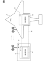
- FIG. 2 is a diagram showing the configuration of an eVTOL and a ground station.
- FIG. 2 is a diagram showing the functional layout of the traffic management system.
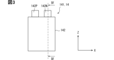
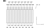
- FIG. FIG. 4 is a cross-sectional view taken along line IV-IV in FIG. 3 .
- FIG. 2 is a diagram showing a battery cell.
- FIG. 2 illustrates a power profile.
- FIG. 13 is a diagram illustrating detection of anomalies when fixed values are used.
- FIG. 1 illustrates an example of a monitoring device.
- FIG. 13 is a diagram illustrating another example of a monitoring device.
- FIG. 13 is a diagram illustrating an example of threshold values stored in a memory.
- FIG. 11 is a diagram illustrating an example of a threshold value set by a setting unit.
- a and/or B means at least one of A and B. In other words, it may include only A, only B, or both A and B.
- An electric flying object includes a motor (rotating electric machine) as a drive source for movement.
- An electric flying object may be called an electric airplane, an electric aircraft, or the like.
- An electric flying object can move in a vertical direction and a horizontal direction.
- An electric flying object can move in a direction having a vertical component and a horizontal component, that is, in a diagonal direction.
- An electric flying object may be, for example, an electric vertical take-off and landing aircraft (eVTOL), an electric short take-off and landing aircraft (eSTOL), a drone, or the like.
- eVTOL is an abbreviation for electronic Vertical Take-Off and Landing aircraft.
- eSTOL is an abbreviation for electronic Short distance Take-Off and Landing aircraft.
- the electric flying vehicle may be either a manned or unmanned vehicle.
- the electric flying vehicle In the case of a manned vehicle, the electric flying vehicle is operated by a pilot who acts as the operator.
- the electric flying vehicle In the case of an unmanned vehicle, the electric flying vehicle may be operated by a remote control by a pilot, or may be automatically controlled by a control system.
- the electric flying vehicle in this embodiment is an eVTOL.
- ⁇ eVTOL> 1 shows an eVTOL and a ground station.
- an eVTOL 10 includes an airframe 11, a fixed wing 12, a rotor 13, a battery 14, an EPU 15, a BMS 16, and the like.
- the aircraft body 11 is the fuselage of the aircraft.
- the aircraft body 11 has a shape that extends in the front-to-rear direction.
- the aircraft body 11 has a passenger compartment for passengers and/or a luggage compartment for carrying luggage.
- the fixed wing 12 is the wing portion of the aircraft and is connected to the aircraft body 11.
- the fixed wing 12 provides gliding lift.
- the gliding lift is the lift generated by the fixed wing 12.
- the fixed wing 12 may have a main wing 121 and a tail 122.
- the main wing 121 extends left and right from near the center in the fore-and-aft direction of the aircraft body 11.
- the tail 122 extends left and right from the rear of the aircraft body 11.
- a plurality of rotors 13 are provided on the aircraft body. At least some of the plurality of rotors 13 may be provided on the fixed wing 12. At least some of the plurality of rotors 13 may be provided on the aircraft body 11. The number of rotors 13 provided on the eVTOL 10 is not particularly limited. A plurality of rotors 13 may be provided on each of the aircraft body 11 and the main wing 121.
- the rotor 13 may be referred to as a rotor, a propeller, a fan, etc.
- the rotor 13 may have blades 131 and a shaft 132.
- the blades 131 are attached to the shaft 132.
- the blades 131 are vanes that rotate together with the shaft 132.
- a plurality of the blades 131 extend radially around the axis of the shaft 132.
- the shaft 132 is the rotation axis of the rotor 13, and is driven to rotate by the motor of the EPU 15.
- the rotor 13 generates a thrust force by rotation.
- the thrust force acts on the eVTOL 10 mainly as rotational lift during takeoff and landing operations of the eVTOL 10.
- the rotor 13 mainly provides rotational lift during takeoff and landing operations.
- Rotational lift is lift generated by the rotation of the rotor 13.
- the rotor 13 may provide only rotational lift, or may provide forward thrust in addition to rotational lift.
- the rotor 13 provides rotational lift when the eVTOL 10 is hovering.
- the propulsive force acts on the eVTOL 10 primarily as thrust during cruising operation of the eVTOL 10.
- the rotor 13 primarily provides thrust during cruising operation. During cruising operation, the rotor 13 may provide thrust alone or may provide lift in addition to thrust.
- the battery (BAT) 14 is a device for driving the rotor 13 to rotate.
- the battery 14 is sometimes called a battery pack.
- the battery 14 can store DC power and has rechargeable battery cells.
- the battery 14 has at least one assembled battery including a plurality of battery cells.
- the battery cell is a secondary battery that generates an electromotive force by a chemical reaction.
- the battery cell is, for example, a lithium ion secondary battery or a nickel-hydrogen secondary battery.
- the battery cell may be a secondary battery with a liquid electrolyte or a so-called all-solid-state battery with a solid electrolyte.
- the battery cell may be configured such that the battery reaction occurs when ions (electrolyte) that contribute to the battery reaction move between the positive and negative electrodes via the electrolytic solution and/or solid electrolyte.
- the eVTOL 10 may be equipped with a fuel cell, a generator, or the like as a power source that supplies power to the device.
- the battery 14 supplies power to the EPU 15.
- the battery 14 may supply power to auxiliary equipment (not shown), such as an air conditioner, the ECU 20 (described below), and a lift adjustment mechanism (not shown).
- the battery 14 of the eVTOL 10 is required to have high capacity as well as high output performance. For this reason, a battery cell that can provide both high capacity and high output is desirable. From the standpoint of output, a battery cell with low resistance over a wide SOC range is desirable. In particular, a battery cell that has low resistance even in the low SOC range and can provide high output is desirable. SOC is an abbreviation for State Of Charge.
- LCO, NMC, NCA, LFP, and LMFP can be used as the positive electrode material of the battery cell.
- LCO is lithium cobalt oxide (LiCoO2).
- NMC is lithium nickel cobalt manganese oxide (Li(NiMnCo)O2).
- NCA is lithium nickel cobalt aluminate (Li(NiCoAl)O2).
- LFP is lithium iron phosphate (LiFePO4).
- LMFP is lithium manganese iron phosphate (LiFexMnyPO4).
- LCO, NMC, and NCA are layered compounds.
- a positive electrode of LMFP which has low resistance in the low SOC region, or a positive electrode made of a blend of LMFP and NMC is preferable.
- Anode materials for battery cells can be carbon-based, such as hard carbon or soft carbon, silicon, lithium-based, or titanium-based, such as LTO or NTO.
- LTO is lithium titanate (Li4Ti5O12).
- NTO is niobium titanium oxide (TiNb2O7).
- Carbon-based and titanium-based anodes, which have low resistance in the low SOC region, are particularly preferred.
- the EPU 15 drives and rotates the rotors 13, which provide propulsive force to the eVTOL 10.
- the EPU 15 is a device for driving and rotating the rotors 13.
- EPU is an abbreviation for Electric Propulsion Unit.
- the EPU 15 corresponds to an electric propulsion device.
- the EPU 15 includes a motor.
- the EPU 15 may include an inverter and an ESC in addition to the motor.
- ESC is an abbreviation for Electronic Speed Controller.
- the number of EPUs 15 may be the same as the number of rotors 13.
- the eVTOL 10 may include six EPUs 15.
- the EPUs 15 and the rotors 13 are connected one-to-one. Alternatively, a configuration in which two or more rotors 13 are connected to one EPU 15 via a gear box may be used.
- BMS 16 monitors the status of the unit batteries that make up battery 14.
- BMS is an abbreviation for Battery Management System.
- BMS 16 can monitor the voltage, current, temperature, internal resistance, SOC, SOH, and other safety-related conditions of battery 14, such as internal pressure and gas leaks.
- SOH is an abbreviation for State Of Health.
- BMS 16 may be provided integrally with battery 14.
- BMS 16 may be provided separately from battery 14. Part of BMS 16 may be provided inside battery 14, and another part may be provided outside battery 14.
- the BMS 16 may be provided individually for each battery pack. One BMS 16 may be provided for multiple battery packs. One BMS 16 may be provided for all battery packs. When multiple BMSs 16 are used, a function to control all BMSs 16 may be provided separately from BMS 16, or may be provided integrally with BMS 16.
- the eVTOL 10 further includes an ECU 20 and auxiliary equipment (not shown). ECU is an abbreviation for Electronic Control Unit.
- the eVTOL 10 may include a lift adjustment mechanism (not shown). The lift adjustment mechanism adjusts the gliding lift of the fixed wing 12. The lift adjustment mechanism increases or decreases the gliding lift generated by the fixed wing 12.
- the eVTOL 10 may include, for example, a tilt mechanism or a flap as the lift adjustment mechanism. The tilt mechanism is driven to adjust the tilt angle of the rotor 13.
- the flap is a movable wing piece provided on the fixed wing 12.
- the traffic management system is a system for formulating flight plans, monitoring flight status, collecting and managing flight information, and supporting flight operations. At least a part of the functions of the traffic management system may be arranged in an onboard computer of the eVTOL 10. At least a part of the functions of the traffic management system may be arranged in an external computer capable of wireless communication with the eVTOL 10.
- the external computer may be a server 31 of a ground station 30 as shown in FIG. 1.
- the ground station 30 is capable of wireless communication with the eVTOL 10.
- the ground stations 30 are capable of wireless communication with each other.
- some of the functions of the traffic management system are placed in the ECU 20 of the eVTOL 10, and some of the functions of the traffic management system are placed in the server 31 of the ground station 30.
- the functions of the traffic management system are shared between the ECU 20 and the server 31.
- the ECU 20 is configured to include a processor (PC) 201, a memory (MM) 202, a storage (ST) 203, and a communication circuit (CC) 204 for wireless communication.
- the processor 201 executes various processes by accessing the memory 202.
- the memory 202 is a rewritable volatile storage medium.
- the memory 202 is, for example, a RAM. RAM is an abbreviation for Random Access Memory.
- the storage 203 is a rewritable non-volatile storage medium.
- the storage 203 stores a program (PG) 203P to be executed by the processor 201.
- the program 203P constructs multiple functional units by having the processor 201 execute multiple instructions.
- the ECU 20 may include multiple processors 201.
- the server 31 is configured to include a processor (PC) 311, a memory (MM) 312, a storage (ST) 313, and a communication circuit (CC) 314.
- the processor 311 executes various processes by accessing the memory 312.
- the memory 312 is a rewritable volatile storage medium, such as a RAM.
- the storage 313 is a rewritable non-volatile storage medium.
- the storage 313 stores a program (PG) 313P to be executed by the processor 311.
- the program 313P constructs multiple functional units by having the processor 311 execute multiple instructions.
- the server 31 may include multiple processors 311.
- FIG. 2 shows an example of the functional layout of the traffic management system.
- the traffic management system 40 shown in FIG. 2 has an external management unit 41 and an on-board management unit 42.
- the external management unit 41 is functionally arranged in the server 31 of the ground station 30.
- the on-board management unit 42 is functionally arranged in the ECU 20 of the eVTOL 10. In this way, some of the functions of the traffic management system 40 may be arranged in the server 31, and other parts of the functions may be arranged in the ECU 20.
- the external management unit 41 and the on-board management unit 42 are capable of wireless communication with each other.
- the on-board management unit 42 is capable of wired or wireless communication with various devices arranged in the eVTOL 10.
- the battery cell 142 has a power generating element and a battery case that houses this power generating element.
- the battery case provides the outer shell of the battery cell 142.
- the battery case may be formed, for example, using a metal material or a laminate film.
- the shape of the battery cell 142, i.e., the battery case, is not particularly limited. It may be rectangular, laminated, or cylindrical.
- the battery pack 141 may include multiple battery cells 142 arranged in the Y direction.
- the arrangement of the battery cells 142 is not limited to the arrangement described above.
- cylindrical battery cells 142 they may be arranged in a staggered pattern when viewed in a plan view from the Z direction.
- FIG. 6 shows the power profile of the eVTOL 10 from takeoff to landing. Note that the power profile of electric flying objects other than the eVTOL 10 is similar to that of the eVTOL 10.
- Period P1 is referred to as takeoff, takeoff flight, takeoff operation, etc.
- Period P2 is referred to as cruising, cruising flight, cruising operation, etc.
- Period P3 is referred to as landing, landing flight, landing operation, etc.
- Periods P1 and P3 are referred to as takeoff and landing, takeoff and landing flight, takeoff and landing operation, etc.
- the required power i.e., the output, is constant throughout almost the entire range of each of periods P1 and P3 in FIG. 6.
- the eVTOL 10 ascends from the takeoff point to the cruise start point. In period P2, the eVTOL 10 cruises at a predetermined altitude. In period P2, the eVTOL 10 descends from the end point of period P2 to the landing point.
- the movement of the eVTOL 10 includes a mainly horizontal component in period P2, and a mainly vertical component in periods P1 and P3. In periods P1 and P3 when moving vertically, high output is required continuously for a predetermined period of time to drive the rotor 13.
- ⁇ Battery voltage> 7 is a diagram showing anomaly detection when a fixed threshold is used, in which the change in battery voltage during flight is shown by a solid line.
- the battery 14 that drives the EPU 15 is required to discharge at a large current for a certain period of time during vertical movement, particularly during takeoff and landing. For example, during takeoff and landing, the battery 14 discharges continuously (continuously) at a maximum discharge rate of about 3C to about 15C for about 30 seconds to about 90 seconds.
- the abnormality can be detected at time t2 by using a relatively high fixed value 1.
- the abnormality can be detected early in this way, erroneous judgments will occur during takeoff and landing because fixed value 1 is high.
- erroneous judgments during takeoff and landing can be avoided by using fixed value 2, which is lower than fixed value 1 and higher than the lower allowable limit of battery 14.
- the abnormality will be detected at time t3, which is later than time t2. In other words, the abnormality cannot be detected early.
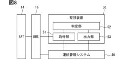
- Fig. 8 shows an example of a monitoring device.
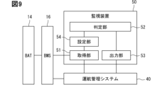
- Fig. 9 shows another example of a monitoring device.
- the monitoring device 50 may include an acquisition unit 51, a determination unit 52, and an output unit 53.
- the monitoring device 50 may further include a setting unit 54.
- the monitoring device 50 monitors the battery 14.
- the functional arrangement of the monitoring device 50 is not particularly limited. At least some of the functions of the monitoring device 50 may be arranged on-board or off-board. The functions of the monitoring device 50 may be distributed across multiple devices on-board. The functions of the monitoring device 50 may be distributed across multiple devices off-board. Some of the functions of the monitoring device 50 may be arranged on-board and another part of the functions may be arranged off-board.
- At least some of the functions of the monitoring device 50 may be arranged in the BMS 16. At least some of the functions of the monitoring device 50 may be arranged in the ECU 20. At least some of the functions of the monitoring device 50 may be arranged in the server 31 of the ground station 30. At least some of the functions of the monitoring device 50 may be arranged in the traffic management system 40. At least some of the functions of the monitoring device 50 may be arranged in the on-board management unit 42. At least some of the functions of the monitoring device 50 may be arranged in the off-board management unit 41.
- the acquisition unit 51 acquires information regarding the voltage of the battery 14 during flight and information regarding the travel mode of the eVTOL 10.
- Information regarding the voltage of the battery 14 during flight may be referred to as battery voltage information or voltage information.
- Information regarding the travel mode may be referred to as travel mode information.
- the acquisition unit 51 may acquire information such as voltage information and travel mode information from the BMS 16, the traffic management system 40, the EPU 15, etc.
- the acquisition unit 51 may acquire actual measured values, intermediate calculated values, or calculated values such as feature quantities as information.
- Information may be acquired by performing calculations within the monitoring device 50 based on actual measured values and intermediate calculated values acquired from the BMS 16, etc.
- the acquisition unit 51 acquires information through wireless communication and/or wired communication.
- the resistance of the battery 14 changes depending on the environmental temperature.
- the battery voltage is affected by the fluctuations in the battery resistance.
- the acquisition unit 51 may acquire environmental information in addition to the voltage information and the travel mode information.
- the environmental information for example, the temperature, wind speed, wind direction, etc. may be acquired. Taking into account the fluctuations in the environmental parameters, the accuracy of determining an abnormality can be improved.
- the eVTOL 10 can have multiple movement modes during flight.
- the movement modes may include a mode in which it moves primarily vertically and a mode in which it moves primarily horizontally. In addition to the vertical and horizontal movement modes, it may also include a mode in which it moves diagonally.
- the eVTOL 10 moves primarily vertically during takeoff and landing, and primarily horizontally during cruising.
- the movement modes may include a takeoff and landing mode and a cruising mode.
- the movement modes may include a takeoff mode, a cruising mode, and a landing mode.
- the cruising mode may be subdivided to take into account cases where it temporarily moves vertically during cruising.
- the acquisition unit 51 may acquire, as the travel mode information, information indicating the travel mode itself, or may acquire information for determining the travel mode.
- the acquisition unit 51 may acquire, as the travel mode information, discharge characteristic information and/or flight information.
- the acquisition unit 51 may have a function of determining the travel mode based on the acquired discharge characteristic information and/or flight information.
- the monitoring device 50 may include a functional unit separate from the acquisition unit 51 that determines the travel mode based on the information acquired by the acquisition unit 51.
- the discharge characteristic information is information related to the discharge current. For example, if the discharge current is equal to or greater than a predetermined threshold, it may be determined to be the vertical travel mode, and if it is less than the threshold, it may be determined to be the horizontal travel mode.
- the flight information may be a signal indicating the travel mode obtained from the traffic management system 40 or the like.
- the flight information may be altitude change information such as the ascent speed and descent speed of the eVTOL 10. For example, if the ascent speed is equal to or greater than a predetermined threshold, it may be determined to be a vertical travel mode, and if it is less than the threshold, it may be determined to be a horizontal travel mode.
- the flight information may be information indicating the orientation of the rotor 13. In a configuration in which the orientation of the rotor 13 can be changed according to the travel mode by a tilt mechanism or the like, the travel mode can be determined from information on the orientation of the rotor 13.
- the flight information may be time information during the flight. If the operation is accurately time-managed, the travel mode may be determined by time. In the case of repeated movement between spots, the operation is accurately time-managed. In particular, in the case of automatic operation, the operation is more accurately time-managed.
- the acquisition unit 51 may acquire information regarding the battery state together with the discharge characteristic information as the travel mode information.
- the battery state information is the open circuit voltage (OCV) and/or resistance.
- OCV is an abbreviation for Open Circuit Voltage.
- SOC is an abbreviation for State Of Charge.
- the determination unit 52 has a function of comparing the voltage information acquired by the acquisition unit 51 with a threshold value set for each travel mode to determine the presence or absence of a battery abnormality.
- the threshold value may be set to a different value for each travel mode.
- the determination unit 52 functions as a detection unit that detects a battery abnormality.
- the determination unit 52 may have a function of determining whether or not abnormality detection is being performed normally based on the voltage information.
- the determination unit 52 may function as a diagnosis unit that diagnoses (determines) whether the abnormality detection function is normal or not.
- the monitoring device 50 may include a diagnosis unit separate from the determination unit 52.
- the monitoring device 50 may include a diagnosis unit separate from the detection unit.
- the determination unit 52 may have a function of limiting abnormality detection and threshold values for a predetermined period of time.
- the determination unit 52 may function as a limiting unit that limits abnormality detection and threshold values.
- the monitoring device 50 may include a limiting unit separate from the determination unit 52 (detection unit).
- the output unit 53 outputs the abnormality determination result to the outside of the monitoring device 50.
- the output unit 53 outputs the monitoring result when a predetermined condition regarding an abnormality in the battery 14 is satisfied.
- the output unit 53 may output the determination result, for example, to issue an alarm to the crew or the ground station 30.
- the output unit 53 may output the determination result to trigger a transition to avoidance operation.
- the output unit 53 may output the determination result to the traffic management system 40 that displays the aircraft's operational status and controls operation.
- the monitoring device 50 itself may display it.
- the output unit 53 may output a control request for avoidance operation to a control device that controls flight.
- the control device may be provided integrally as a function of the traffic management system 40, or may be provided separately.
- the output unit 53 may output in multiple stages, such as an alarm in the first stage and an avoidance action in the second stage and beyond.
- an avoidance action for example, a redundant operation of the battery 14 may be adopted, or an emergency landing action may be adopted.
- the redundant operation of the battery 14 may, for example, stop the output of the system with an abnormality and continue the flight with the remaining system.
- multiple actions may be executed simultaneously.
- the avoidance action may be one that can be performed in stages.
- the output unit 53 may estimate the time until an abnormality occurs based on the time series progression of the target information, and output it as urgency information.
- the setting unit 54 sets a threshold value for comparison with the voltage information based on the travel mode information acquired by the acquisition unit 51.
- the setting unit 54 sets a threshold value for each travel mode.
- the setting unit 54 may set the threshold value to a different value for each travel mode.
- the setting unit 54 may set the threshold value based on the discharge characteristic information and battery state information, which are the travel mode information.
- the threshold is set individually for each travel mode.
- the threshold is set according to the travel mode.
- the threshold may be associated with the relationship with the travel mode and stored in advance in the memory.
- the determination unit 52 reads out the threshold corresponding to the travel mode from the memory and uses it for determination.
- FIG. 10 shows an example of the threshold stored in the memory.
- the travel mode includes two types, a takeoff and landing mode and a cruising mode.
- the memory stores a threshold Th1 corresponding to the takeoff and landing mode and a threshold Th2 corresponding to the cruising mode.
- the determination unit 52 makes a determination using the threshold Th1 in the takeoff and landing mode, and makes a determination using the threshold Th2 in the cruising mode.
- the threshold Th1 is set to a value lower than the threshold Th2 and higher than the allowable lower limit.
- the threshold value may be set with a certain margin of error for the voltage behavior, derived, for example, from prior experiments or battery simulations, to derive normal voltage behavior during flight.
- the margin of error is, for example, the margin for variations in battery discharge characteristics, fluctuations in OCV or battery resistance, and errors in the detection system.
- Threshold values may be prepared for each flight plan, for example, differences in flight routes.
- the threshold may be set by the setting unit 54 according to the travel mode.
- the setting unit 54 may set the threshold based on the discharge characteristic information and battery state information acquired by the acquisition unit 51.
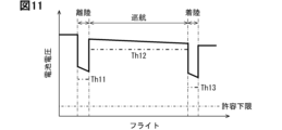
- FIG. 11 shows an example of the threshold set by the setting unit 54.
- FIG. 12 shows another example of the threshold set by the setting unit 54.
- the travel mode includes three types: takeoff mode, cruising mode, and landing mode.
- the setting unit 54 sets a threshold Th11 corresponding to the takeoff mode, a threshold Th12 corresponding to the cruising mode, and a threshold Th13 corresponding to the landing mode.
- Battery voltage during discharge OCV - discharge current x battery resistance (Equation 1)
- the OCV decreases with a decrease in the SOC. It is advisable to prepare an SOC-OCV map in advance and calculate the OCV from the SOC value. The SOC decreases during landing compared to takeoff. For this reason, as shown in FIG. 11, it is advisable to set the threshold value Th13 set during landing lower than the threshold value Th11 set during takeoff.
- the resistance of the battery 14 also changes with the SOC. It is advisable to determine the behavior of the resistance in advance through experiments, etc., and calculate it using a map model or regression model. Many of the battery cells 142 have a tendency for the resistance to increase in the low SOC range.
- the setting unit 54 should reflect the resistance in the threshold setting, particularly in flights that use the low SOC range.
- the setting unit 54 may set the threshold value using information updated before flight by a battery status diagnosis performed when the aircraft is parked between flights.
- the battery status diagnosis may include an AC impedance diagnosis. Parameters of a battery equivalent circuit model and a battery reaction model, such as DC resistance, battery reaction resistance, and diffusion resistance, may be obtained. This allows the voltage fluctuation during discharge (during flight) to be simulated immediately before flight, resulting in higher accuracy.
- the setting unit 54 may sequentially change the set threshold value based on changes in the battery state during flight. As shown in FIG. 12, the setting unit 54 may sequentially change the threshold value in accordance with fluctuations in battery voltage. This enables earlier and more accurate detection of abnormalities.
- the setting unit 54 may set the threshold value based on an operation plan when planning an operation.
- the setting unit 54 may set the threshold value according to actual results during flight.
- the threshold value based on the plan may be updated according to actual results.
- the setting unit 54 may use, as the battery state information, information on the increase in resistance caused by the concentration bias of the ions that contribute to the battery reaction.
- a temporary bias occurs in the concentration distribution of the ions that contribute to the battery reaction.
- the concentration bias occurs in the electrolyte and electrodes.
- the concentration bias occurs, the internal resistance of the battery 14 increases temporarily (reversibly). As a result, even if the SOC of the battery 14 is sufficient, the output performance of the battery 14 decreases. In this way, temporary (reversible) deterioration occurs in the battery 14.
- the temporary deterioration is sometimes called high-rate deterioration.
- the setting unit 54 can predict the degree of temporary deterioration and reflect it in the threshold value, enabling earlier and more accurate abnormality detection.
- the setting unit 54 may predict primary deterioration in advance and reflect it in the threshold value.
- the setting unit 54 may acquire information regarding the degree of temporary degradation of the battery 14, or may calculate the degree of temporary degradation based on the acquired information.
- the degree of temporary degradation is the difference from a reference value of the internal resistance.
- the reference value may be, for example, the initial internal resistance value before takeoff for the current flight.
- the reference value may be the internal resistance value after processing to eliminate temporary degradation, or the internal resistance value after charging on the ground.
- the reference value is preferably the internal resistance value after temporary degradation has been sufficiently eliminated.
- the calculation of the degree of temporary degradation may be an actual measurement calculation based on an actual measurement value, or a predictive calculation based on a predictive value.
- the calculated value may be the degree of temporary degradation at the time of monitoring, or the degree of temporary degradation at the time of takeoff or landing.
- the setting unit 54 may predict the degree of primary degradation in advance and reflect it in the threshold value.
- the setting unit 54 may predict the degree of primary degradation in advance by calculating a fluctuation profile of primary degradation based on a discharge profile planned for the flight.
- the setting unit 54 may predict the degree of primary degradation based on, for example, a prediction map, or may predict based on a prediction model such as multiple regression.
- the degree of primary degradation may be predicted based on a prediction model generated using machine learning.
- the setting unit 54 may predict the degree of temporary deterioration in advance by calculating a fluctuation profile of temporary deterioration using past history data.
- the history data may be information regarding the past degree of temporary deterioration where the takeoff point and/or landing point and aircraft type match the target flight.
- the operation plan of the eVTOL 10 is finite and is repeated frequently, so history information can be utilized. Furthermore, since history information on takeoff points and landing points, which are prone to prediction errors, is utilized, the prediction accuracy of the degree of temporary deterioration can be improved. Ease of operation, output characteristics, etc. differ depending on the model (type) of the eVTOL 10. This can further improve the prediction accuracy of the degree of temporary deterioration.
- the setting unit 54 may set a threshold value according to the degree of increase (actual results) of temporary degradation during flight.
- the setting unit 54 may update the prediction-based threshold value according to the actual results.
- the setting unit 54 may calculate the degree of temporary degradation based on the output history of the battery.
- the setting unit 54 may calculate the integrated value of the discharge current during flight as the degree of temporary degradation. When charging is performed, the integrated value of the charge and discharge current may be used as the degree of temporary degradation. Stopping output during standby on the ground and temporary stoppage of output during flight also act to eliminate the concentration bias caused by discharge to some extent. Therefore, the current integrated value may be corrected in the direction of eliminating the concentration bias.
- the current value and/or duration may be weighted during integration.
- the weighting coefficient may be calculated using a map or regression model created in advance from experimental data, etc.
- the setting unit 54 may use a battery physics model to calculate the degree of temporary deterioration.
- the battery physics model models electrochemical reactions and material transport, and is capable of analyzing concentration distribution. By inputting the current history into this battery physics model and performing calculations, it is possible to estimate the concentration bias of ions in the electrolyte and electrodes that contribute to the battery reaction.
- the setting unit 54 may calculate the degree of temporary degradation based on the battery resistance.
- the setting unit 54 may calculate the amount of increase (amount of change) in the internal resistance, i.e., the degree of temporary degradation itself. The amount of change becomes a decrease when the temporary degradation is eliminated.
- the amount of increase in the resistance of the battery 14 can be calculated using the time series values of the internal resistance calculated from the voltage, current, etc. of the battery 14.
- the setting unit 54 may calculate the degree of temporary degradation using an estimated resistance based on a battery model.
- the battery model is, for example, a battery equivalent circuit model.
- the estimated resistance is found from an estimated current estimated from a battery model that assumes a uniform concentration distribution, and an actual measured voltage.
- the degree of temporary degradation can be calculated from the difference between the estimated resistance and the measured resistance found from the actual measured current and voltage.
- the setting unit 54 may calculate the degree of temporary degradation based on the resistance component of the AC impedance.
- the increase (change) in the resistance component of the AC impedance of the battery 14 can be used as the degree of temporary degradation.
- the setting unit 54 may calculate the degree of temporary deterioration based on historical information of past flights. As historical information, information regarding the past degree of temporary deterioration where the takeoff point and/or landing point and aircraft type match the target flight may be used.
- the operation plan of the eVTOL 10 is finite and is repeated frequently, so historical information can be utilized. Furthermore, since historical information on takeoff points and landing points, which are prone to prediction errors, is utilized, the prediction accuracy of the degree of temporary deterioration can be improved. Ease of operation, output characteristics, etc. differ depending on the model (type) of the eVTOL 10. This can further improve the prediction accuracy of the degree of temporary deterioration.
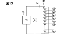
- Fig. 13 shows the battery pack voltage Vb and the cell voltage Vc.
- Fig. 14 shows an example of threshold setting when the voltage change rate is used.
- Fig. 15 shows an example of threshold setting when the cell voltage variation is used.
- the threshold for the takeoff and landing mode is set to Th21, and the threshold for the cruising mode is set to Th22.
- the threshold for the takeoff and landing mode is set to Th31, and the threshold for the cruising mode is set to Th32.
- the acquisition unit 51 may acquire, as the battery information, the absolute value of the assembled battery voltage Vb shown in FIG. 13.
- the acquisition unit 51 may acquire the absolute value of each cell voltage Vc.
- the acquisition unit 51 may acquire, as the battery information, the voltage change rate as shown in FIG. 14.
- the voltage change rate may be the change rate of the assembled battery voltage Vb or the change rate of the cell voltage Vc.
- the acquisition unit 51 may acquire, as the battery information, the variation in the cell voltage Vc as shown in FIG. 15.
- the acquisition unit 51 may acquire at least one of the following battery information: absolute value of the battery pack voltage Vb, absolute value of each cell voltage Vc, rate of change of the battery pack voltage Vb, rate of change of the cell voltage Vc, and variation of the cell voltage Vc. By monitoring multiple parameters such as absolute value, rate of change, and variation, it becomes possible to detect abnormalities in the battery 14 with higher accuracy.
- monitoring device 50 may be disposed in ECU 20 of eVTOL 10. In this case, execution of processing of each functional block of monitoring device 50 by processor 201 corresponds to execution of the monitoring method.
- the monitoring device may be disposed in server 31 of ground station 30. In this case, execution of processing of each functional block of monitoring device 50 by processor 311 corresponds to execution of the monitoring method.
- the method shown in FIG. 16 may be used.
- the monitoring device 50 (for example, the processor 201) repeatedly executes the process shown in FIG. 16 at a predetermined cycle.
- the monitoring device 50 acquires information (step S10).
- the monitoring device 50 acquires travel mode information and voltage information of the battery 14.
- the monitoring device 50 may acquire the above-mentioned flight information as the travel mode information.
- the monitoring device 50 may acquire discharge characteristic information of the battery 14 as the travel mode information.
- the monitoring device 50 may acquire flight information and discharge characteristic information as the travel mode information.
- the monitoring device 50 may acquire discharge characteristic information and battery status information as the travel mode information.
- the monitoring device 50 may acquire flight information, discharge characteristic information, and battery status information as the travel mode information.
- the monitoring device 50 may acquire flight information, discharge characteristic information, and battery status information as the travel mode information.
- the monitoring device 50 sets a threshold value for each travel mode individually (step S20).
- the monitoring device 50 may read a threshold value corresponding to the travel mode from memory and set it.
- the monitoring device 50 may set a threshold value by calculation or the like based on travel mode information.
- the monitoring device 50 may set a threshold value based on discharge characteristic information and battery state information.
- the monitoring device 50 compares the acquired voltage information with a threshold value and determines whether the voltage information is outside the allowable threshold range (step S30). For example, the monitoring device 50 may determine that the voltage information is outside the allowable threshold range when the absolute value of the assembled battery voltage Vb is less than the threshold value, and may determine that the voltage information is within the allowable threshold range when the absolute value of the assembled battery voltage Vb is equal to or greater than the threshold value. The monitoring device 50 may determine that the voltage information is outside the allowable threshold range when the absolute value of the assembled battery voltage Vc is less than the threshold value, and may determine that the voltage information is within the allowable threshold range when the absolute value of the assembled battery voltage Vc is equal to or greater than the threshold value.
- the monitoring device 50 may determine that the voltage information is outside the allowable threshold range when the rate of change of the assembled battery voltage Vb is greater than the threshold value, and may determine that the voltage information is within the allowable threshold range when the rate of change of the cell voltage Vc is greater than the threshold value, and may determine that the voltage information is within the allowable threshold range when the rate of change of the cell voltage Vc is greater than the threshold value.
- the monitoring device 50 may determine that the voltage information is outside the allowable threshold range when the rate of change of the cell voltage Vc is greater than the threshold value, and may determine that the voltage information is within the allowable threshold range when the rate of change of the cell voltage Vc is less than the threshold value.
- the monitoring device 50 may determine that the voltage information is outside the allowable threshold range when the variation of the cell voltage Vc is greater than the threshold value, and may determine that the voltage information is within the allowable threshold range when the variation of the cell voltage Vc is less than the threshold value.
- the monitoring device 50 determines that there is an abnormality in the battery 14, outputs an abnormality (step S40), and ends the series of processes. If the voltage information is within the allowable threshold range, the monitoring device 50 does not execute the process of step S40 and ends the series of processes.
- the method shown in FIG. 17 may be used as a monitoring method.
- the monitoring device 50 executes the process of step S10, similar to the method shown in FIG. 16.
- the monitoring device 50 determines whether or not it is outside of a predetermined period during transition (step S15).
- the monitoring device 50 determines whether or not it is outside of a predetermined period during transition between vertical movement and horizontal movement.
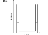
- the equivalent circuit of the battery 14 includes a capacitor component connected in parallel to a resistor. Therefore, as shown in FIG. 18, fluctuations in the battery voltage cause a transient response that corresponds to the capacitor component. For example, a transient response occurs when switching from takeoff to cruising. The battery voltage also fluctuates suddenly when transitioning (switching) between vertical and horizontal movement. Therefore, as shown in FIG. 19, divergence of the voltage change rate occurs during the transition. Also, delays in signal propagation in the circuit can cause delays in threshold switching.
- the timing corresponds to a predetermined period during the transition when the above-mentioned sudden voltage fluctuation, delay in voltage fluctuation, and delay in threshold switching may occur.
- the predetermined period is at least a part of the period during the transition.
- the predetermined period may be set based on the derived periods, for example, by using prior experiments or battery simulations to derive the period of normal sudden fluctuation in voltage information during the transition, the delay period in battery voltage fluctuation due to normal transient response, and the delay period in threshold switching.
- the derived periods may also be set with a predetermined margin of error.
- step S15 If in step S15 it is determined that the period is outside the specified period, the monitoring device 50 executes the processing from step S20 onwards, similar to the method shown in FIG. 16. On the other hand, if it is determined that the period is not outside the specified period, that is, that the period is within the specified period, the monitoring device 50, for example, restricts monitoring (step S21). The monitoring device 50 excludes the specified period from detecting anomalies. The monitoring device 50 does not detect anomalies based on voltage information for the specified period. The monitoring restriction can be applied to any of the sudden voltage fluctuations, delayed voltage fluctuations, and delayed threshold switching described above.
- the monitoring device 50 may execute a process of applying the threshold value before the transition instead of limiting the monitoring.
- the threshold value set during vertical movement is maintained for a predetermined period during the transition from vertical movement to horizontal movement.
- the application of the threshold value before the transition can be applied to the delay in voltage fluctuation and the delay in threshold switching described above.
- the monitoring device 50 may execute a process of applying the upper limit or lower limit voltage allowed for the battery 14 as a threshold instead of limiting the monitoring.
- the application of the allowable upper limit or lower limit voltage can be applied to the delay in voltage fluctuation and the delay in threshold switching described above. In this way, the threshold value may be limited to a predetermined value.
- the monitoring device 50 executes the processes from step S30 onwards in the same manner as the method shown in FIG. 16.
- the method shown in FIG. 20 may be used as a monitoring method.
- the monitoring device 50 executes the processes of steps S10 and S20 in the same manner as the method shown in FIG. 16.
- the monitoring device 50 judges whether the difference between the assembled battery voltage Vb and the sum of all the cell voltages Vc is equal to or less than a predetermined value (step S25).
- the monitoring device 50 diagnoses that the detection of anomalies is performed normally.
- the sum of all the cell voltages Vc is the sum of the voltages (cell voltages Vc) of all the battery cells 142 in the assembled battery 141 that generate the assembled battery voltage Vb.
- the predetermined value may be set based on the difference between the normal assembled battery voltage Vb during flight and the sum of all the cell voltages Vc, derived, for example, using a prior experiment or a battery simulation.
- the predetermined value may be set with a predetermined margin for the derived difference.
- step S25 If it is determined in step S25 that the difference is within the predetermined value, the monitoring device 50 executes the process from step S30 onwards, similar to the method shown in FIG. 16. On the other hand, if it is determined that the difference is not below the predetermined value, that is, that the difference is greater than the predetermined value, the monitoring device 50 outputs a message indicating that a monitoring anomaly is suspected (step S41) and ends the series of processes. If the difference is not below the predetermined value, the monitoring device 50 does not execute the processes of steps S30 and S40, that is, does not detect an anomaly, and ends the series of processes.
- the monitoring device 50 may output that there is no abnormality and then end the series of processes. The same applies to the method shown in FIG. 17 and the method shown in FIG. 20.
- the determination unit 52 (detection unit) of the monitoring device 50 may execute the process of step S15 and the process of step S21 shown in FIG. 17.
- a functional unit other than the determination unit 52 may execute at least one of the process of step S15 and the process of step S21.
- the battery 14 is required to discharge a large current for a certain period of time.
- Monitoring the battery voltage which reacts sensitively to internal short circuits and rapid deterioration that can cause thermal runaway in the battery 14, is used as a means of early detection of abnormalities.
- the discharge load of the battery 14 fluctuates greatly, and the battery voltage also fluctuates drastically. For this reason, it is difficult to detect abnormalities early using management that uses a fixed value (constant value) as a threshold value.
- the monitoring device 50 of this embodiment obtains information about the travel mode along with the voltage information of the battery 14, and monitors the voltage information using a threshold value set for each travel mode. This makes it possible to detect abnormalities in the battery 14 at an early stage, thereby improving flight safety.
- the monitoring device 50 is preferably applied to a configuration in which the maximum discharge rate of the battery 14 during vertical movement of the eVTOL 10 is 1.5 times or more the maximum discharge rate during horizontal movement.
- the monitoring device 50 is preferably applied to a configuration in which the discharge rate during vertical movement is 3C or more.
- electric flying objects such as the eVTOL 10 have large fluctuations in the discharge characteristics.
- the greater the fluctuations in the discharge characteristics the greater the effect of early detection by the monitoring device 50.
- the ratio of the maximum discharge rate during vertical movement to the maximum discharge rate during horizontal movement is 1.5 times or more, the effect of early detection is greater.
- the ratio is even higher, for example, 2 times or more, 3 times or more, or 5 times or more, a greater effect can be achieved.
- the higher the discharge rate during vertical movement the greater the effect of early detection by the monitoring device 50.
- the discharge rate is 3C or more, the effect of early detection is greater.
- the discharge rate is even higher, for example, 5C or more, 7C or more, or 10C or more, a greater effect can be achieved.
- the monitoring device 50 may acquire battery discharge characteristic information and/or flight information as information related to the travel mode. By using this information, the threshold value can be switched at an appropriate timing according to the travel mode.
- the monitoring device 50 sets a threshold value for each travel mode based on discharge characteristic information and battery state information, which are information related to the travel mode. As shown in Equation 1, a predetermined relationship is established between the battery voltage, OCV, discharge current, and battery resistance during discharge. By reflecting the discharge characteristic information (discharge current) and battery state information (OCV, battery resistance), which affect the battery voltage, in the threshold setting, it becomes possible to detect abnormalities more quickly and with higher accuracy.
- the monitoring device 50 may use information on the increase in resistance caused by the concentration bias of ions that contribute to the battery reaction to set the threshold value. This can reduce false detections caused by the increase in resistance due to temporary deterioration and increase the reliability of abnormality detection.
- the monitoring device 50 may use battery status information that is updated before flight by a battery status diagnosis performed when the aircraft is parked.
- the battery status information is updated for each flight.
- the monitoring device 50 may change the threshold value based on changes in the battery state during flight. By changing the threshold value according to fluctuations in the battery voltage, it becomes possible to detect abnormalities earlier and with higher accuracy.
- the monitoring device 50 may acquire at least one of the following voltage information: the absolute value of the assembled battery voltage Vb, the absolute value of the cell voltage Vc, the rate of change of the assembled battery voltage Vb, the rate of change of the cell voltage Vc, and the variation of the cell voltage Vc.
- the monitoring device 50 may obtain, as voltage information, information relating to the battery pack voltage Vb and information relating to the cell voltage Vc from different sources.
- the monitoring device 50 may obtain the battery pack voltage information from the EPU 15 and the cell voltage information from the BMS 16. Reliability can be improved by monitoring using data from different independent measurements, i.e., multiplexing of diagnoses.
- the monitoring device 50 may diagnose whether abnormality detection is being performed normally using the battery pack voltage Vb and the total voltage obtained by adding up all the cell voltages Vc in the battery pack 141. This can prevent erroneous abnormality detection.
- the monitoring device 50 may either limit the detection of anomalies, apply the threshold value before the transition, or apply the upper or lower limit voltage allowable for the battery 14 as the threshold value. This makes it possible to suppress erroneous determinations due to normal sudden fluctuations in battery voltage information, delays in fluctuations in battery voltage due to normal transient responses, and delays in threshold switching. This makes it possible to increase the reliability of anomaly detection.
- the monitoring method of this embodiment is executed by a processor to monitor the battery 14.
- the monitoring method involves acquiring voltage information and travel mode information of the battery 14 during flight, and outputting a monitoring result if a predetermined condition related to an abnormality in the battery 14 is met using the voltage information and a threshold value set for each travel mode. In this way, because a threshold value set for each travel mode is used, an abnormality in the battery 14 can be detected early, thereby improving flight safety.
- the program of this embodiment is stored in a storage medium to monitor the battery 14, and includes instructions to be executed by a processor.
- the program includes instructions to acquire voltage information and travel mode information of the battery 14 during flight, and to output a monitoring result when a predetermined condition related to an abnormality in the battery 14 is met using the voltage information and a threshold value set for each travel mode. In this way, because a threshold value set for each travel mode is used, an abnormality in the battery 14 can be detected early, thereby improving flight safety.
- the disclosure in this specification and drawings, etc. is not limited to the exemplified embodiments.
- the disclosure includes the exemplified embodiments and modifications by those skilled in the art based thereon.
- the disclosure is not limited to the combination of parts and/or elements shown in the embodiments.
- the disclosure can be implemented by various combinations.
- the disclosure can have additional parts that can be added to the embodiments.
- the disclosure includes the omission of parts and/or elements of the embodiments.
- the disclosure includes the replacement or combination of parts and/or elements between one embodiment and another embodiment.
- the disclosed technical scope is not limited to the description of the embodiments. Some disclosed technical scopes are indicated by the description of the claims, and should be interpreted as including all modifications within the meaning and scope equivalent to the description of the claims.
- the devices, systems, and methods thereof described in this disclosure may also be realized by a dedicated computer comprising a processor programmed to execute one or more functions embodied in a computer program.
- the devices and methods described in this disclosure may also be realized using dedicated hardware logic circuits.
- the devices and methods described in this disclosure may also be realized by one or more dedicated computers configured by combining a processor that executes a computer program with one or more hardware logic circuits.
- processor 311 may be realized as hardware. Aspects of realizing a certain function as hardware include a configuration in which it is realized using one or more ICs.
- a processor computational core
- CPU is an abbreviation for Central Processing Unit.
- MPU is an abbreviation for Micro-Processing Unit.
- GPU is an abbreviation for Graphics Processing Unit.
- DFP is an abbreviation for Data Flow Processor.
- processor 201 may be realized by combining multiple types of arithmetic processing devices. Some or all of the functions of processor 201 may be realized using SoC, ASIC, FPGA, etc. SoC is an abbreviation for System on Chip. ASIC is an abbreviation for Application Specific Integrated Circuit. FPGA is an abbreviation for Field-Programmable Gate Array. The same applies to processor 311.
- the computer program may also be stored in a computer-readable non-transitory tangible storage medium as instructions executed by a computer.
- HDD can be used as a storage medium for the program.
- HDD is an abbreviation for Hard-disk Drive.
- SSD is an abbreviation for Solid State Drive.
- the scope of this disclosure also includes forms such as programs for causing a computer to function as a control device or control system, and non-transitory tangible storage media such as semiconductor memory on which the programs are recorded.
- the acquisition unit acquires the discharge characteristic information and the battery state information as information related to the travel mode
- the monitoring device further comprising a setting unit (54) that sets the threshold for each of the travel modes based on the discharge characteristic information and the battery state information.
- the battery includes a battery pack (141) including a plurality of battery cells (142), A monitoring device described in any one of technical ideas 1 to 8, wherein the acquisition unit acquires at least one of the absolute value of the assembled battery voltage, the absolute value of the cell voltage, the rate of change of the assembled battery voltage, the rate of change of the cell voltage, and the variation of the cell voltage as the voltage information.
- the monitoring device described in Technical Idea 10 includes a diagnosis unit (52) that diagnoses whether abnormality detection is being performed normally using the assembled battery voltage and a total voltage obtained by adding up all of the cell voltages in the assembled battery.
- a monitoring device described in any one of technical ideas 1 to 11, comprising a limiting unit (52) that performs one of the following during a predetermined period during the transition between vertical movement and horizontal movement: limiting the detection of abnormalities, applying the threshold value before the transition, and applying an upper limit voltage or a lower limit voltage allowable for the battery as the threshold value.
- a limiting unit (52) that performs one of the following during a predetermined period during the transition between vertical movement and horizontal movement: limiting the detection of abnormalities, applying the threshold value before the transition, and applying an upper limit voltage or a lower limit voltage allowable for the battery as the threshold value.
Landscapes
- Engineering & Computer Science (AREA)
- Aviation & Aerospace Engineering (AREA)
- Physics & Mathematics (AREA)
- General Physics & Mathematics (AREA)
- Remote Sensing (AREA)
- Chemical & Material Sciences (AREA)
- Combustion & Propulsion (AREA)
- Automation & Control Theory (AREA)
- Radar, Positioning & Navigation (AREA)
- General Chemical & Material Sciences (AREA)
- Electrochemistry (AREA)
- Chemical Kinetics & Catalysis (AREA)
- Manufacturing & Machinery (AREA)
- Transportation (AREA)
- Power Engineering (AREA)
- Electric Propulsion And Braking For Vehicles (AREA)
- Charge And Discharge Circuits For Batteries Or The Like (AREA)
- Secondary Cells (AREA)
Abstract
Description
電動飛行体に搭載された電池を監視する監視装置であって、
飛行時における電池の電圧情報と、電動飛行体の移動モードに関する情報と、を取得する取得部と、
電圧情報と、移動モードごとに設定される閾値と、を用いて電池の異常に関する所定の条件を満たす場合、監視結果を出力する出力部と、を備える。
電動飛行体に搭載された電池を監視するために、プロセッサにより実行される監視方法であって、
飛行時における電池の電圧情報と、電動飛行体の移動モードに関する情報と、を取得し、
電圧情報と、移動モードごとに設定される閾値と、を用いて電池の異常に関する所定の条件を満たす場合、監視結果を出力する、ことを含む。
電動飛行体に搭載された電池を監視するために記憶媒体に記憶され、プロセッサに実行させる命令を含むプログラムであって、
飛行時における電池の電圧情報と、電動飛行体の移動モードに関する情報と、を取得すること、
電圧情報と、移動モードごとに設定される閾値と、を用いて電池の異常に関する所定の条件を満たす場合、監視結果を出力すること、を実行させる命令を含む。
電動飛行体は、移動するための駆動源としてモータ(回転電機)を備える。電動飛行体は、電動飛行機、電動航空機などと称されることがある。電動飛行体は、鉛直方向への移動、水平方向への移動が可能である。電動飛行体は、鉛直方向成分および水平方向成分を有する方向、つまり斜め方向への移動が可能である。電動飛行体は、たとえば電動垂直離着陸機(eVTOL)、電動短距離離着陸機(eSTOL)、ドローンなどである。eVTOLは、electronic Vertical Take-Off and Landing aircraftの略称である。eSTOLは、electronic Short distance Take-Off and Landing aircraftの略称である。
図1は、eVTOLおよび地上局を示している。図1に示すように、eVTOL10は、機体本体11、固定翼12、回転翼13、電池14、EPU15、およびBMS16などを備えている。
運航管理システムは、運航計画の立案、運航状況の監視、運航に関する情報の収集と管理、運航のサポートなどを行うためのシステムである。運航管理システムの機能の少なくとも一部は、eVTOL10の機内コンピュータに配置されてもよい。運航管理システムの機能の少なくとも一部は、eVTOL10と無線通信可能な外部のコンピュータに配置されてもよい。外部コンピュータは、図1に示すように地上局30のサーバ31でもよい。地上局30は、eVTOL10と無線通信が可能である。地上局30は、地上局同士で無線通信が可能である。
図3は、電池14の一例を示している。図4は、図3のIV-IV線に沿う断面図である。図4では、電池セルの構成を簡素化して図示している。図5は、電極端子の配置を示す図である。以下において、各電池セルの高さ方向をZ方向、Z方向に直交する一方向をY方向、Z方向およびY方向の両方向に直交する方向をX方向と示す。図4においては、便宜上、電池セルの全体に金属ハッチングを施している。
図6は、eVTOL10の離陸から着陸までの電力プロファイルを示している。なお、eVTOL10以外の電動飛行体の電力プロファイルも、eVTOL10と同様である。期間P1は、離陸時、離陸飛行時、離陸動作時などと称される。期間P2は、巡航時、巡航飛行時、巡航動作時などと称される。期間P3は、着陸時、着陸飛行時、着陸動作時などと称される。期間P1,P3は、離着陸時、離着陸飛行時、離着陸動作時などと称される。便宜上、図6では期間P1,P3それぞれのほぼ全域において、必要電力、つまり出力を一定としている。
図7は、固定閾値を用いた場合の異常の検知を示す図である。図7では、飛行(フライト)中における電池電圧の変化を実線で示している。
図8は、監視装置の一例を示している。図9は、監視装置の別例を示している。図8に示すように、監視装置50は、取得部51、判定部52、および出力部53を備えてもよい。図9に示すように、監視装置50は、さらに設定部54を備えてもよい。
閾値は、移動モードごとに個別に設定される。閾値は、移動モードに応じて設定される。閾値は、移動モードとの関係が紐づけられて予めメモリに格納されたものでもよい。判定部52は、移動モードに応じた閾値をメモリから読み出して判定に用いる。図10は、メモリに格納された閾値の一例を示している。移動モードが、離着陸モードと巡航モードの2種類を含んでいる。メモリには、離着陸モードに対応する閾値Th1と、巡航モードに対応する閾値Th2が格納されている。判定部52は、離着陸モードにおいて閾値Th1を用いて判定を行い、巡航モードにおいて閾値Th2を用いて判定を行う。閾値Th1は、閾値Th2よりも低い値であって許容下限よりも高い値とされている。
放電時の電池電圧=OCV-放電電流×電池抵抗・・・(式1)
OCVは、SOCの低下にともなって低下する。SOC-OCVマップを予め作成しておき、SOC値からOCVを算出するとよい。着陸時は、離陸時に較べてSOCが低下する。このため、図11に示すように、着陸時に設定する閾値Th13を、離陸時に設定する閾値Th11に対して低く設定するとよい。
図13は、組電池電圧Vb、セル電圧Vcを示している。図14は、電圧変化率を用いた場合の閾値設定の一例を示している。図15は、セル電圧のばらつきを用いた場合の閾値設定の一例を示している。図14では、離着陸モードの閾値をTh21、巡航モードの閾値をTh22としている。図15では、離着陸モードの閾値をTh31、巡航モードの閾値をTh32としている。
上記したように監視装置50は、eVTOL10のECU20に配置されてもよい。この場合、プロセッサ201によって監視装置50の各機能ブロックの処理が実行されることが、監視方法が実行されることに相当する。監視装置は、地上局30のサーバ31に配置されてもよい。この場合、プロセッサ311によって監視装置50の各機能ブロックの処理が実行されることが、監視方法が実行されることに相当する。
上記したように、eVTOL10(電動飛行体)が鉛直方向に移動する際、電池14には所定時間、大電流での放電が要求される。電池14の熱暴走の要因となる内部短絡や急激な劣化に対して敏感に反応する電池電圧の監視は、異常の早期検出の手段として用いられる。しかしながら、飛行中は電池14の放電負荷変動が大きく、電池電圧の変動も激しい。このため、閾値として固定値(一定値)を用いた管理では、異常を早期に検知することが困難である。
この明細書および図面等における開示は、例示された実施形態に制限されない。開示は、例示された実施形態と、それらに基づく当業者による変形態様を包含する。たとえば、開示は、実施形態において示された部品および/または要素の組み合わせに限定されない。開示は、多様な組み合わせによって実施可能である。開示は、実施形態に追加可能な追加的な部分をもつことができる。開示は、実施形態の部品および/または要素が省略されたものを包含する。開示は、ひとつの実施形態と他の実施形態との間における部品および/または要素の置き換え、または組み合わせを包含する。開示される技術的範囲は、実施形態の記載に限定されない。開示されるいくつかの技術的範囲は、請求の範囲の記載によって示され、さらに請求の範囲の記載と均等の意味および範囲内でのすべての変更を含むものと解されるべきである。
この明細書は、以下に列挙する複数の項に記載された複数の技術的思想を開示している。いくつかの項は、後続の項において先行する項を択一的に引用する多項従属形式(a multiple dependent form)により記載されている場合がある。さらに、いくつかの項は、他の多項従属形式の項を引用する多項従属形式(a multiple dependent form referring to another multiple dependent form)により記載されている場合がある。これらの多項従属形式で記載された項は、複数の技術的思想を定義している。
電動飛行体(10)に搭載された電池(14)を監視する監視装置であって、
飛行時における前記電池の電圧情報と、前記電動飛行体の移動モードに関する情報と、を取得する取得部(51)と、
前記電圧情報と、前記移動モードごとに設定される閾値と、を用いて前記電池の異常に関する所定の条件を満たす場合、監視結果を出力する出力部(53)と、を備える、監視装置。
前記電動飛行体の鉛直方向移動時における前記電池の最大放電レートは、水平方向移動時における最大放電レートの1.5倍以上である、技術的思想1に記載の監視装置。
前記鉛直方向移動時の放電レートが3C以上である、技術的思想2に記載の監視装置。
前記取得部は、前記移動モードに関する情報として、前記電池の放電特性情報および/または飛行情報を取得する、技術的思想1~3いずれかひとつに記載の監視装置。
前記取得部は、前記移動モードに関する情報として、前記放電特性情報と電池状態情報を取得し、
前記放電特性情報および前記電池状態情報に基づいて、前記移動モードごとに前記閾値を設定する設定部(54)を備える、技術的思想4に記載の監視装置。
前記電池状態情報は、電池反応に寄与するイオンの濃度偏りに起因して生じる抵抗増加の情報を含む、技術的思想5に記載の監視装置。
前記設定部は、機駐時に実施の電池状態診断により飛行前に更新される前記電池状態情報を用いる、技術的思想5または技術的思想6に記載の監視装置。
前記設定部は、設定する前記閾値を飛行中の電池状態の変化に基づいて逐次変化させる、技術的思想5~7いずれかひとつに記載の監視装置。
前記電池は、複数の電池セル(142)を備えて構成される組電池(141)を含み、
前記取得部は、前記電圧情報として、組電池電圧の絶対値、セル電圧の絶対値、前記組電池電圧の変化率、前記セル電圧の変化率、および前記セル電圧のばらつきの少なくともひとつを取得する、技術的思想1~8いずれかひとつに記載の監視装置。
前記取得部は、前記電圧情報として、前記組電池電圧に関する情報と前記セル電圧に関する情報とを、互いに異なる取得対象から取得する、技術的思想9に記載の監視装置。
前記組電池電圧と前記組電池内のすべての前記セル電圧を加算した総電圧とを用いて、異常の検知が正常に行われていることを診断する診断部(52)を備える、技術的思想10に記載の監視装置。
鉛直方向移動と水平方向移動との移行時の所定期間において、異常の検知を制限、移行前の前記閾値を適用、および前記閾値として前記電池に許容される上限電圧または下限電圧を適用、のいずれかを実行する制限部(52)を備える、技術的思想1~11いずれかひとつに記載の監視装置。
Claims (14)
- 電動飛行体(10)に搭載された電池(14)を監視する監視装置であって、
飛行時における前記電池の電圧情報と、前記電動飛行体の移動モードに関する情報と、を取得する取得部(51)と、
前記電圧情報と、前記移動モードごとに設定される閾値と、を用いて前記電池の異常に関する所定の条件を満たす場合、監視結果を出力する出力部(53)と、を備える、監視装置。 - 前記電動飛行体の鉛直方向移動時における前記電池の最大放電レートは、水平方向移動時における最大放電レートの1.5倍以上である、請求項1に記載の監視装置。
- 前記鉛直方向移動時の放電レートが3C以上である、請求項2に記載の監視装置。
- 前記取得部は、前記移動モードに関する情報として、前記電池の放電特性情報および/または飛行情報を取得する、請求項1に記載の監視装置。
- 前記取得部は、前記移動モードに関する情報として、前記放電特性情報と電池状態情報を取得し、
前記放電特性情報および前記電池状態情報に基づいて、前記移動モードごとに前記閾値を設定する設定部(54)を備える、請求項4に記載の監視装置。 - 前記電池状態情報は、電池反応に寄与するイオンの濃度偏りに起因して生じる抵抗増加の情報を含む、請求項5に記載の監視装置。
- 前記設定部は、機駐時に実施の電池状態診断により飛行前に更新される前記電池状態情報を用いる、請求項5に記載の監視装置。
- 前記設定部は、設定する前記閾値を飛行中の電池状態の変化に基づいて逐次変化させる、請求項5~7いずれか1項に記載の監視装置。
- 前記電池は、複数の電池セル(142)を備えて構成される組電池(141)を含み、
前記取得部は、前記電圧情報として、組電池電圧の絶対値、セル電圧の絶対値、前記組電池電圧の変化率、前記セル電圧の変化率、および前記セル電圧のばらつきの少なくともひとつを取得する、請求項1に記載の監視装置。 - 前記取得部は、前記電圧情報として、前記組電池電圧に関する情報と前記セル電圧に関する情報とを、互いに異なる取得対象から取得する、請求項9に記載の監視装置。
- 前記組電池電圧と前記組電池内のすべての前記セル電圧を加算した総電圧とを用いて、異常の検知が正常に行われていることを診断する診断部(52)を備える、請求項10に記載の監視装置。
- 鉛直方向移動と水平方向移動との移行時の所定期間において、異常の検知を制限、移行前の前記閾値を適用、および前記閾値として前記電池に許容される上限電圧または下限電圧を適用、のいずれかを実行する制限部(52)を備える、請求項1に記載の監視装置。
- 電動飛行体(10)に搭載された電池(14)を監視するために、プロセッサ(201)により実行される監視方法であって、
飛行時における前記電池の電圧情報と、前記電動飛行体の移動モードに関する情報と、を取得し、
前記電圧情報と、前記移動モードごとに設定される閾値と、を用いて前記電池の異常に関する所定の条件を満たす場合、監視結果を出力する、ことを含む、監視方法。 - 電動飛行体(10)に搭載された電池(14)を監視するために記憶媒体(203)に記憶され、プロセッサ(201)に実行させる命令を含むプログラムであって、
飛行時における前記電池の電圧情報と、前記電動飛行体の移動モードに関する情報と、を取得すること、
前記電圧情報と、前記移動モードごとに設定される閾値と、を用いて前記電池の異常に関する所定の条件を満たす場合、監視結果を出力すること、を実行させる前記命令を含む、プログラム。
Priority Applications (2)
| Application Number | Priority Date | Filing Date | Title |
|---|---|---|---|
| EP24823159.9A EP4730480A1 (en) | 2023-06-14 | 2024-05-15 | Monitoring device, monitoring method, and program |
| US19/415,085 US20260099160A1 (en) | 2023-06-14 | 2025-12-10 | Monitoring device, monitoring method, and non-transitory computer readable storage medium |
Applications Claiming Priority (2)
| Application Number | Priority Date | Filing Date | Title |
|---|---|---|---|
| JP2023097930A JP2024179237A (ja) | 2023-06-14 | 2023-06-14 | 監視装置、監視方法、およびプログラム |
| JP2023-097930 | 2023-06-14 |
Related Child Applications (1)
| Application Number | Title | Priority Date | Filing Date |
|---|---|---|---|
| US19/415,085 Continuation US20260099160A1 (en) | 2023-06-14 | 2025-12-10 | Monitoring device, monitoring method, and non-transitory computer readable storage medium |
Publications (1)
| Publication Number | Publication Date |
|---|---|
| WO2024257537A1 true WO2024257537A1 (ja) | 2024-12-19 |
Family
ID=93852062
Family Applications (1)
| Application Number | Title | Priority Date | Filing Date |
|---|---|---|---|
| PCT/JP2024/017891 Ceased WO2024257537A1 (ja) | 2023-06-14 | 2024-05-15 | 監視装置、監視方法、およびプログラム |
Country Status (4)
| Country | Link |
|---|---|
| US (1) | US20260099160A1 (ja) |
| EP (1) | EP4730480A1 (ja) |
| JP (1) | JP2024179237A (ja) |
| WO (1) | WO2024257537A1 (ja) |
Citations (3)
| Publication number | Priority date | Publication date | Assignee | Title |
|---|---|---|---|---|
| JP2008092656A (ja) * | 2006-09-30 | 2008-04-17 | Sanyo Electric Co Ltd | 車両用の電源装置 |
| JP2016210403A (ja) * | 2016-01-22 | 2016-12-15 | オービタルワークス株式会社 | 無人飛行体 |
| WO2021176580A1 (ja) * | 2020-03-04 | 2021-09-10 | 三菱電機株式会社 | モータ制御装置 |
-
2023
- 2023-06-14 JP JP2023097930A patent/JP2024179237A/ja active Pending
-
2024
- 2024-05-15 EP EP24823159.9A patent/EP4730480A1/en active Pending
- 2024-05-15 WO PCT/JP2024/017891 patent/WO2024257537A1/ja not_active Ceased
-
2025
- 2025-12-10 US US19/415,085 patent/US20260099160A1/en active Pending
Patent Citations (3)
| Publication number | Priority date | Publication date | Assignee | Title |
|---|---|---|---|---|
| JP2008092656A (ja) * | 2006-09-30 | 2008-04-17 | Sanyo Electric Co Ltd | 車両用の電源装置 |
| JP2016210403A (ja) * | 2016-01-22 | 2016-12-15 | オービタルワークス株式会社 | 無人飛行体 |
| WO2021176580A1 (ja) * | 2020-03-04 | 2021-09-10 | 三菱電機株式会社 | モータ制御装置 |
Also Published As
| Publication number | Publication date |
|---|---|
| EP4730480A1 (en) | 2026-04-22 |
| US20260099160A1 (en) | 2026-04-09 |
| JP2024179237A (ja) | 2024-12-26 |
Similar Documents
| Publication | Publication Date | Title |
|---|---|---|
| US20200277080A1 (en) | Systems and methods for in-flight operational assessment | |
| US20210070457A1 (en) | Methods and systems for altering power during flight | |
| EP3947073A1 (en) | Systems and methods for maintaining attitude control under degraded energy source conditions using multiple propulsors | |
| EP4137348B1 (en) | Estimating available power for an aircraft battery | |
| US11858376B2 (en) | System for monitoring a battery system in-flight and a method for its use | |
| US20250191427A1 (en) | Abnormality sign diagnosis device, navigation management system, and computer readable medium | |
| US20250368342A1 (en) | Controller, control method, and control program | |
| US20250249791A1 (en) | Monitor, controller, operation management system, and storage medium | |
| US20250253676A1 (en) | Battery system | |
| US20250290709A1 (en) | Monitoring device, control device, operation management system, and medium | |
| US20260099160A1 (en) | Monitoring device, monitoring method, and non-transitory computer readable storage medium | |
| US20260104466A1 (en) | Monitoring device and non-transitory computer readable storage medium | |
| US20250238031A1 (en) | Control device, operation management system, and non-transitory computer readable medium | |
| EP4711278A1 (en) | Control device, control method, and control program | |
| US20250076395A1 (en) | Method of determining a remaining operating time of an electrical energy storage unit in an aircraft | |
| US20250191476A1 (en) | Cruising distance calculation device, navigation management system, and computer readable medium | |
| US20260118886A1 (en) | System and methods for battery management and control of an electric vehicle |
Legal Events
| Date | Code | Title | Description |
|---|---|---|---|
| 121 | Ep: the epo has been informed by wipo that ep was designated in this application |
Ref document number: 24823159 Country of ref document: EP Kind code of ref document: A1 |
|
| WWE | Wipo information: entry into national phase |
Ref document number: 2024823159 Country of ref document: EP |
|
| NENP | Non-entry into the national phase |
Ref country code: DE |
|
| ENP | Entry into the national phase |
Ref document number: 2024823159 Country of ref document: EP Effective date: 20260114 |
|
| ENP | Entry into the national phase |
Ref document number: 2024823159 Country of ref document: EP Effective date: 20260114 |
|
| ENP | Entry into the national phase |
Ref document number: 2024823159 Country of ref document: EP Effective date: 20260114 |
|
| ENP | Entry into the national phase |
Ref document number: 2024823159 Country of ref document: EP Effective date: 20260114 |
|
| WWP | Wipo information: published in national office |
Ref document number: 2024823159 Country of ref document: EP |