WO2024257528A1 - 圧縮機及び冷凍装置 - Google Patents
圧縮機及び冷凍装置 Download PDFInfo
- Publication number
- WO2024257528A1 WO2024257528A1 PCT/JP2024/017699 JP2024017699W WO2024257528A1 WO 2024257528 A1 WO2024257528 A1 WO 2024257528A1 JP 2024017699 W JP2024017699 W JP 2024017699W WO 2024257528 A1 WO2024257528 A1 WO 2024257528A1
- Authority
- WO
- WIPO (PCT)
- Prior art keywords
- refrigerant
- rotor
- rotating member
- space
- stator
- Prior art date
- Legal status (The legal status is an assumption and is not a legal conclusion. Google has not performed a legal analysis and makes no representation as to the accuracy of the status listed.)
- Ceased
Links
Images






Classifications
-
- F—MECHANICAL ENGINEERING; LIGHTING; HEATING; WEAPONS; BLASTING
- F04—POSITIVE - DISPLACEMENT MACHINES FOR LIQUIDS; PUMPS FOR LIQUIDS OR ELASTIC FLUIDS
- F04C—ROTARY-PISTON, OR OSCILLATING-PISTON, POSITIVE-DISPLACEMENT MACHINES FOR LIQUIDS; ROTARY-PISTON, OR OSCILLATING-PISTON, POSITIVE-DISPLACEMENT PUMPS
- F04C29/00—Component parts, details or accessories of pumps or pumping installations, not provided for in groups F04C18/00 - F04C28/00
- F04C29/0042—Driving elements, brakes, couplings, transmissions specially adapted for pumps
- F04C29/0085—Prime movers
-
- F—MECHANICAL ENGINEERING; LIGHTING; HEATING; WEAPONS; BLASTING
- F04—POSITIVE - DISPLACEMENT MACHINES FOR LIQUIDS; PUMPS FOR LIQUIDS OR ELASTIC FLUIDS
- F04C—ROTARY-PISTON, OR OSCILLATING-PISTON, POSITIVE-DISPLACEMENT MACHINES FOR LIQUIDS; ROTARY-PISTON, OR OSCILLATING-PISTON, POSITIVE-DISPLACEMENT PUMPS
- F04C23/00—Combinations of two or more pumps, each being of rotary-piston or oscillating-piston type, specially adapted for elastic fluids; Pumping installations specially adapted for elastic fluids; Multi-stage pumps specially adapted for elastic fluids
- F04C23/008—Hermetic pumps
-
- F—MECHANICAL ENGINEERING; LIGHTING; HEATING; WEAPONS; BLASTING
- F04—POSITIVE - DISPLACEMENT MACHINES FOR LIQUIDS; PUMPS FOR LIQUIDS OR ELASTIC FLUIDS
- F04B—POSITIVE-DISPLACEMENT MACHINES FOR LIQUIDS; PUMPS
- F04B35/00—Piston pumps specially adapted for elastic fluids and characterised by the driving means to their working members, or by combination with, or adaptation to, specific driving engines or motors, not otherwise provided for
- F04B35/04—Piston pumps specially adapted for elastic fluids and characterised by the driving means to their working members, or by combination with, or adaptation to, specific driving engines or motors, not otherwise provided for the means being electric
-
- F—MECHANICAL ENGINEERING; LIGHTING; HEATING; WEAPONS; BLASTING
- F04—POSITIVE - DISPLACEMENT MACHINES FOR LIQUIDS; PUMPS FOR LIQUIDS OR ELASTIC FLUIDS
- F04B—POSITIVE-DISPLACEMENT MACHINES FOR LIQUIDS; PUMPS
- F04B39/00—Component parts, details, or accessories, of pumps or pumping systems specially adapted for elastic fluids, not otherwise provided for in, or of interest apart from, groups F04B25/00 - F04B37/00
- F04B39/02—Lubrication
- F04B39/0223—Lubrication characterised by the compressor type
- F04B39/023—Hermetic compressors
-
- F—MECHANICAL ENGINEERING; LIGHTING; HEATING; WEAPONS; BLASTING
- F04—POSITIVE - DISPLACEMENT MACHINES FOR LIQUIDS; PUMPS FOR LIQUIDS OR ELASTIC FLUIDS
- F04B—POSITIVE-DISPLACEMENT MACHINES FOR LIQUIDS; PUMPS
- F04B39/00—Component parts, details, or accessories, of pumps or pumping systems specially adapted for elastic fluids, not otherwise provided for in, or of interest apart from, groups F04B25/00 - F04B37/00
- F04B39/02—Lubrication
- F04B39/0223—Lubrication characterised by the compressor type
- F04B39/023—Hermetic compressors
- F04B39/0238—Hermetic compressors with oil distribution channels
- F04B39/0246—Hermetic compressors with oil distribution channels in the rotating shaft
-
- F—MECHANICAL ENGINEERING; LIGHTING; HEATING; WEAPONS; BLASTING
- F04—POSITIVE - DISPLACEMENT MACHINES FOR LIQUIDS; PUMPS FOR LIQUIDS OR ELASTIC FLUIDS
- F04B—POSITIVE-DISPLACEMENT MACHINES FOR LIQUIDS; PUMPS
- F04B39/00—Component parts, details, or accessories, of pumps or pumping systems specially adapted for elastic fluids, not otherwise provided for in, or of interest apart from, groups F04B25/00 - F04B37/00
- F04B39/12—Casings; Cylinders; Cylinder heads; Fluid connections
- F04B39/121—Casings
-
- F—MECHANICAL ENGINEERING; LIGHTING; HEATING; WEAPONS; BLASTING
- F04—POSITIVE - DISPLACEMENT MACHINES FOR LIQUIDS; PUMPS FOR LIQUIDS OR ELASTIC FLUIDS
- F04C—ROTARY-PISTON, OR OSCILLATING-PISTON, POSITIVE-DISPLACEMENT MACHINES FOR LIQUIDS; ROTARY-PISTON, OR OSCILLATING-PISTON, POSITIVE-DISPLACEMENT PUMPS
- F04C18/00—Rotary-piston pumps specially adapted for elastic fluids
- F04C18/02—Rotary-piston pumps specially adapted for elastic fluids of arcuate-engagement type, i.e. with circular translatory movement of co-operating members, each member having the same number of teeth or tooth-equivalents
-
- F—MECHANICAL ENGINEERING; LIGHTING; HEATING; WEAPONS; BLASTING
- F04—POSITIVE - DISPLACEMENT MACHINES FOR LIQUIDS; PUMPS FOR LIQUIDS OR ELASTIC FLUIDS
- F04C—ROTARY-PISTON, OR OSCILLATING-PISTON, POSITIVE-DISPLACEMENT MACHINES FOR LIQUIDS; ROTARY-PISTON, OR OSCILLATING-PISTON, POSITIVE-DISPLACEMENT PUMPS
- F04C18/00—Rotary-piston pumps specially adapted for elastic fluids
- F04C18/02—Rotary-piston pumps specially adapted for elastic fluids of arcuate-engagement type, i.e. with circular translatory movement of co-operating members, each member having the same number of teeth or tooth-equivalents
- F04C18/0207—Rotary-piston pumps specially adapted for elastic fluids of arcuate-engagement type, i.e. with circular translatory movement of co-operating members, each member having the same number of teeth or tooth-equivalents both members having co-operating elements in spiral form
- F04C18/0215—Rotary-piston pumps specially adapted for elastic fluids of arcuate-engagement type, i.e. with circular translatory movement of co-operating members, each member having the same number of teeth or tooth-equivalents both members having co-operating elements in spiral form where only one member is moving
-
- F—MECHANICAL ENGINEERING; LIGHTING; HEATING; WEAPONS; BLASTING
- F04—POSITIVE - DISPLACEMENT MACHINES FOR LIQUIDS; PUMPS FOR LIQUIDS OR ELASTIC FLUIDS
- F04C—ROTARY-PISTON, OR OSCILLATING-PISTON, POSITIVE-DISPLACEMENT MACHINES FOR LIQUIDS; ROTARY-PISTON, OR OSCILLATING-PISTON, POSITIVE-DISPLACEMENT PUMPS
- F04C23/00—Combinations of two or more pumps, each being of rotary-piston or oscillating-piston type, specially adapted for elastic fluids; Pumping installations specially adapted for elastic fluids; Multi-stage pumps specially adapted for elastic fluids
-
- F—MECHANICAL ENGINEERING; LIGHTING; HEATING; WEAPONS; BLASTING
- F04—POSITIVE - DISPLACEMENT MACHINES FOR LIQUIDS; PUMPS FOR LIQUIDS OR ELASTIC FLUIDS
- F04C—ROTARY-PISTON, OR OSCILLATING-PISTON, POSITIVE-DISPLACEMENT MACHINES FOR LIQUIDS; ROTARY-PISTON, OR OSCILLATING-PISTON, POSITIVE-DISPLACEMENT PUMPS
- F04C29/00—Component parts, details or accessories of pumps or pumping installations, not provided for in groups F04C18/00 - F04C28/00
- F04C29/02—Lubrication; Lubricant separation
-
- F—MECHANICAL ENGINEERING; LIGHTING; HEATING; WEAPONS; BLASTING
- F04—POSITIVE - DISPLACEMENT MACHINES FOR LIQUIDS; PUMPS FOR LIQUIDS OR ELASTIC FLUIDS
- F04C—ROTARY-PISTON, OR OSCILLATING-PISTON, POSITIVE-DISPLACEMENT MACHINES FOR LIQUIDS; ROTARY-PISTON, OR OSCILLATING-PISTON, POSITIVE-DISPLACEMENT PUMPS
- F04C29/00—Component parts, details or accessories of pumps or pumping installations, not provided for in groups F04C18/00 - F04C28/00
- F04C29/02—Lubrication; Lubricant separation
- F04C29/023—Lubricant distribution through a hollow driving shaft
-
- F—MECHANICAL ENGINEERING; LIGHTING; HEATING; WEAPONS; BLASTING
- F04—POSITIVE - DISPLACEMENT MACHINES FOR LIQUIDS; PUMPS FOR LIQUIDS OR ELASTIC FLUIDS
- F04C—ROTARY-PISTON, OR OSCILLATING-PISTON, POSITIVE-DISPLACEMENT MACHINES FOR LIQUIDS; ROTARY-PISTON, OR OSCILLATING-PISTON, POSITIVE-DISPLACEMENT PUMPS
- F04C29/00—Component parts, details or accessories of pumps or pumping installations, not provided for in groups F04C18/00 - F04C28/00
- F04C29/02—Lubrication; Lubricant separation
- F04C29/026—Lubricant separation
-
- F—MECHANICAL ENGINEERING; LIGHTING; HEATING; WEAPONS; BLASTING
- F25—REFRIGERATION OR COOLING; COMBINED HEATING AND REFRIGERATION SYSTEMS; HEAT PUMP SYSTEMS; MANUFACTURE OR STORAGE OF ICE; LIQUEFACTION SOLIDIFICATION OF GASES
- F25B—REFRIGERATION MACHINES, PLANTS OR SYSTEMS; COMBINED HEATING AND REFRIGERATION SYSTEMS; HEAT PUMP SYSTEMS
- F25B31/00—Compressor arrangements
- F25B31/02—Compressor arrangements of motor-compressor units
-
- F—MECHANICAL ENGINEERING; LIGHTING; HEATING; WEAPONS; BLASTING
- F04—POSITIVE - DISPLACEMENT MACHINES FOR LIQUIDS; PUMPS FOR LIQUIDS OR ELASTIC FLUIDS
- F04C—ROTARY-PISTON, OR OSCILLATING-PISTON, POSITIVE-DISPLACEMENT MACHINES FOR LIQUIDS; ROTARY-PISTON, OR OSCILLATING-PISTON, POSITIVE-DISPLACEMENT PUMPS
- F04C18/00—Rotary-piston pumps specially adapted for elastic fluids
- F04C18/08—Rotary-piston pumps specially adapted for elastic fluids of intermeshing-engagement type, i.e. with engagement of co-operating members similar to that of toothed gearing
- F04C18/12—Rotary-piston pumps specially adapted for elastic fluids of intermeshing-engagement type, i.e. with engagement of co-operating members similar to that of toothed gearing of other than internal-axis type
- F04C18/14—Rotary-piston pumps specially adapted for elastic fluids of intermeshing-engagement type, i.e. with engagement of co-operating members similar to that of toothed gearing of other than internal-axis type with toothed rotary pistons
- F04C18/16—Rotary-piston pumps specially adapted for elastic fluids of intermeshing-engagement type, i.e. with engagement of co-operating members similar to that of toothed gearing of other than internal-axis type with toothed rotary pistons with helical teeth, e.g. chevron-shaped, screw type
-
- F—MECHANICAL ENGINEERING; LIGHTING; HEATING; WEAPONS; BLASTING
- F04—POSITIVE - DISPLACEMENT MACHINES FOR LIQUIDS; PUMPS FOR LIQUIDS OR ELASTIC FLUIDS
- F04C—ROTARY-PISTON, OR OSCILLATING-PISTON, POSITIVE-DISPLACEMENT MACHINES FOR LIQUIDS; ROTARY-PISTON, OR OSCILLATING-PISTON, POSITIVE-DISPLACEMENT PUMPS
- F04C2210/00—Fluid
- F04C2210/26—Refrigerants with particular properties, e.g. HFC-134a
-
- F—MECHANICAL ENGINEERING; LIGHTING; HEATING; WEAPONS; BLASTING
- F04—POSITIVE - DISPLACEMENT MACHINES FOR LIQUIDS; PUMPS FOR LIQUIDS OR ELASTIC FLUIDS
- F04C—ROTARY-PISTON, OR OSCILLATING-PISTON, POSITIVE-DISPLACEMENT MACHINES FOR LIQUIDS; ROTARY-PISTON, OR OSCILLATING-PISTON, POSITIVE-DISPLACEMENT PUMPS
- F04C2240/00—Components
- F04C2240/30—Casings or housings
-
- F—MECHANICAL ENGINEERING; LIGHTING; HEATING; WEAPONS; BLASTING
- F04—POSITIVE - DISPLACEMENT MACHINES FOR LIQUIDS; PUMPS FOR LIQUIDS OR ELASTIC FLUIDS
- F04C—ROTARY-PISTON, OR OSCILLATING-PISTON, POSITIVE-DISPLACEMENT MACHINES FOR LIQUIDS; ROTARY-PISTON, OR OSCILLATING-PISTON, POSITIVE-DISPLACEMENT PUMPS
- F04C2240/00—Components
- F04C2240/40—Electric motor
-
- F—MECHANICAL ENGINEERING; LIGHTING; HEATING; WEAPONS; BLASTING
- F04—POSITIVE - DISPLACEMENT MACHINES FOR LIQUIDS; PUMPS FOR LIQUIDS OR ELASTIC FLUIDS
- F04C—ROTARY-PISTON, OR OSCILLATING-PISTON, POSITIVE-DISPLACEMENT MACHINES FOR LIQUIDS; ROTARY-PISTON, OR OSCILLATING-PISTON, POSITIVE-DISPLACEMENT PUMPS
- F04C2240/00—Components
- F04C2240/60—Shafts
-
- F—MECHANICAL ENGINEERING; LIGHTING; HEATING; WEAPONS; BLASTING
- F04—POSITIVE - DISPLACEMENT MACHINES FOR LIQUIDS; PUMPS FOR LIQUIDS OR ELASTIC FLUIDS
- F04C—ROTARY-PISTON, OR OSCILLATING-PISTON, POSITIVE-DISPLACEMENT MACHINES FOR LIQUIDS; ROTARY-PISTON, OR OSCILLATING-PISTON, POSITIVE-DISPLACEMENT PUMPS
- F04C29/00—Component parts, details or accessories of pumps or pumping installations, not provided for in groups F04C18/00 - F04C28/00
- F04C29/02—Lubrication; Lubricant separation
- F04C29/028—Means for improving or restricting lubricant flow
-
- F—MECHANICAL ENGINEERING; LIGHTING; HEATING; WEAPONS; BLASTING
- F04—POSITIVE - DISPLACEMENT MACHINES FOR LIQUIDS; PUMPS FOR LIQUIDS OR ELASTIC FLUIDS
- F04C—ROTARY-PISTON, OR OSCILLATING-PISTON, POSITIVE-DISPLACEMENT MACHINES FOR LIQUIDS; ROTARY-PISTON, OR OSCILLATING-PISTON, POSITIVE-DISPLACEMENT PUMPS
- F04C29/00—Component parts, details or accessories of pumps or pumping installations, not provided for in groups F04C18/00 - F04C28/00
- F04C29/04—Heating; Cooling; Heat insulation
- F04C29/045—Heating; Cooling; Heat insulation of the electric motor in hermetic pumps
Definitions
- This disclosure relates to compressors and refrigeration devices.
- Patent Document 1 JP Patent Publication No. 2021-017849 adjusts the dimensions of the balance weight attached to the underside of the motor rotor and the relative position of the balance weight to other parts.
- the refrigerant located below the motor contains lubricating oil. If the refrigerant in this state reaches the compressor's discharge pipe, the lubricating oil will be discharged outside the compressor. In order to reduce the discharge of lubricating oil, it is desirable to optimize the structure of not only the balance weight but also the group of parts located near the bottom of the motor, thereby making it easier to separate the lubricating oil contained in the refrigerant from the refrigerant.
- the compressor of the first aspect comprises a casing, a motor, a compression mechanism, an oil sump, a crankshaft, a rotating member, a first space, a second space, and a discharge pipe.
- the casing has an internal space.
- the motor has a cylindrical stator, a rotor disposed in the stator, a refrigerant descending passage, and a refrigerant ascending passage.
- the motor is disposed in the internal space.
- the compression mechanism is disposed in the internal space and above the motor.
- the compression mechanism forms a first space between the motor and the oil sump.
- the compression mechanism compresses the refrigerant.
- the oil sump is disposed in the internal space and below the motor.
- the oil sump forms a second space between the motor and the oil sump.
- the crankshaft transmits rotation of the rotor to the compression mechanism.
- the rotating member rotates together with the rotor.
- the rotating member is disposed in the second space.
- the rotating member has an outer diameter larger than the inner diameter of the stator.
- the discharge pipe is disposed in the first space.
- the refrigerant descending passage passes the refrigerant from the first space to the second space.
- the refrigerant ascending passage passes the refrigerant from the second space to the first space.
- the rotating member is located between the discharge pipe and the oil reservoir. Therefore, the refrigerant rising from the oil reservoir to the discharge pipe through the refrigerant ascending passage collides with the rotating member that functions as an obstacle to the refrigerant, so the lubricating oil contained in the refrigerant is separated, and the discharge of lubricating oil from the compressor is suppressed.
- the compressor of the second aspect is the compressor of the first aspect, in which the stator has a stator core and a coil.
- the coil is formed by winding a conductive wire around the stator core.
- the refrigerant descending passage is a core cut formed on the outer periphery of the stator core.
- the rotating member is positioned lower than the lower end of the coil.
- the refrigerant undergoes cyclone separation in the first space, which separates a predetermined amount of lubricating oil, and then it can descend into the second space through the core cut on the outer periphery.
- the refrigerant attempting to rise from the second space adjacent to the oil reservoir to the coil gap of the motor collides with a rotating member disposed below the motor coil before reaching the coil gap of the motor, further promoting separation of the lubricating oil from the refrigerant. Because the cross-sectional area of the coil gap accounts for a large proportion of the area through which the ascending refrigerant flow passes, separation of the lubricating oil is efficient.
- the compressor of the third aspect is the compressor of the second aspect, in which the height difference between the rotating member and the lower end of the coil is 20 mm or less.
- the rotating member is positioned close to the lower end of the coil. Therefore, the rotating member can function as an obstacle to the refrigerant.
- the compressor of the fourth aspect is the compressor of the second or third aspect, in which the stator further has an annular lower insulator.
- the lower insulator is disposed on the lower surface of the stator core.
- the lower insulator has an outer peripheral wall extending downward from near the outer periphery of the lower insulator.
- the rotating member is disposed higher than the lower end of the outer peripheral wall.
- the compressor of the fifth aspect is any one of the compressors of the first aspect to the fourth aspect, in which the rotating member has grooves extending radially from the center to the periphery.
- the compressor of the sixth aspect is any one of the compressors of the first aspect to the fourth aspect, in which the rotating member has a plurality of grooves extending radially from the center to the periphery.
- the compressor of the seventh aspect is the compressor of any one of the first aspect to the sixth aspect, in which the rotor has a rotor refrigerant passage.
- the rotor refrigerant passage penetrates the rotor in the axial direction.
- the rotor refrigerant passage passes refrigerant from the second space to the first space.
- An air gap is formed between the stator and the rotor, which passes refrigerant from the second space to the first space.
- the stator has a coil gap located between two adjacent coils. The coil gap passes refrigerant from the second space to the first space.
- the rotating member blocks the entire rotor refrigerant passage, the entire air gap, and at least a portion of the coil gap. Therefore, a large proportion of the upward flow of the refrigerant collides with the rotating member.
- the compressor of the eighth aspect is any one of the compressors of the first aspect to the seventh aspect, in which the rotor has a rotor body and a lower balance weight provided on the underside of the rotor body.
- the rotating member is fixed to the lower balance weight.
- the rotor has a lower balance weight. Therefore, vibrations during rotor rotation can be suppressed.
- the compressor of the ninth aspect is any one of the compressors of the first aspect to the seventh aspect, in which the rotor has a rotor body and a lower balance weight provided on the lower surface of the rotor body.
- the rotating member is fixed to the rotor body.
- the rotating member is fixed to the rotor body. Therefore, the rotating member can block the center of the upward flow of the refrigerant.
- the compressor of the tenth aspect is any one of the compressors of the first aspect to the seventh aspect, in which the rotating member is fixed to the crankshaft.
- the rotating member is fixed to the crankshaft. Therefore, the rotating member can block the upward flow of the refrigerant near the crankshaft.
- the compressor of the eleventh aspect is any one of the compressors of the first aspect to the tenth aspect, in which the rotating member has at least one of a first opening communicating with the rotor refrigerant passage and a second opening communicating with the air gap.
- the rotating member has a first opening or a second opening. Therefore, a portion of the upward flow of the refrigerant can pass through either the rotor refrigerant passage, the air gap, or the coil gap after passing through the first opening or the second opening, so that the required amount of upward flow of the refrigerant can be secured.
- the refrigeration device of the twelfth aspect includes any one of the compressors of the first aspect to the eleventh aspect.
- the compressor has a rotating member that functions as an obstacle to the refrigerant. Therefore, the discharge of lubricating oil from the compressor in the refrigeration device's refrigerant circuit is suppressed.
- FIG. 1 is a circuit diagram showing the configuration of a refrigeration device 101 according to the first embodiment.
- FIG. 2 is a cross-sectional view showing the configuration of the compressor 100 according to the first embodiment.
- FIG. 3 is an enlarged schematic view of a main part of FIG.
- FIG. 4 is a plan view of the stator core 22.
- FIG. 5 is a schematic diagram showing a top view or a cross section of a main part of the compressor 100.
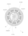
- FIG. 6 is a schematic diagram showing the bottom surface of the rotating member 60.
- FIG. 7 is an enlarged schematic view of a main part of FIG.
- FIG. 8 is a cross-sectional view of the rotating member 60.
- FIG. 1 is a circuit diagram showing the configuration of a refrigeration device 101 according to the first embodiment.
- FIG. 2 is a cross-sectional view showing the configuration of the compressor 100 according to the first embodiment.
- FIG. 3 is an enlarged schematic view of a main part of FIG.
- FIG. 4 is a plan view of
- FIG. 9 is a schematic diagram showing the bottom or cross section of a main part of the compressor 100.
- FIG. 10 is an enlarged schematic view of a main part of a compressor 100 according to the second embodiment.
- FIG. 11 is a schematic diagram showing the bottom surface of a rotating member 60 according to the second embodiment.
- First Embodiment 1 shows the configuration of a refrigeration device 101 according to the first embodiment.
- the refrigeration device 101 has a heat source unit 90, a utilization unit 80, and a communication pipe group 85.
- the heat source unit 90 functions as a heat source or cold source for the refrigerant R.
- the heat source unit 90 has a compressor 100, a four-way switching valve 92, a heat source heat exchanger 93, a heat source fan 94, an expansion valve 95, an accumulator 96, a liquid shutoff valve 97, and a gas shutoff valve 98.
- the utilization unit 80 provides the user with the heat or cold received from the refrigerant R.
- the utilization unit 80 has a utilization heat exchanger 81 and a utilization fan 82.
- the interconnecting piping group 85 connects the heat source unit 90 and the utilization unit 80.
- the interconnecting piping group 85 has a liquid pipe 86 and a gas pipe 87.
- the liquid pipe 86 connects the liquid shutoff valve 97 and the utilization heat exchanger 81.
- the gas pipe 87 connects the gas shutoff valve 98 and the utilization heat exchanger 81.
- the components of the heat source unit 90, the components of the utilization unit 80, and the interconnecting pipe group 85 constitute a refrigerant circuit.
- the refrigerant circuit circulates the refrigerant R.
- the compressor 100 mounted on the heat source unit 90 generates high-pressure gas refrigerant (i.e., refrigerant R that has a high pressure and is in a gaseous state) by compressing low-pressure gas refrigerant (i.e., refrigerant R that has a low pressure and is in a gaseous state).
- high-pressure gas refrigerant i.e., refrigerant R that has a high pressure and is in a gaseous state
- low-pressure gas refrigerant i.e., refrigerant R that has a low pressure and is in a gaseous state
- the refrigeration device 101 When the four-way switching valve 92 realizes the connection shown by the solid lines, the refrigeration device 101 operates in cold heat utilization mode. At this time, the utilization heat exchanger 81 functions as an evaporator or heat absorber, and provides the cold heat obtained from the refrigerant R to the user. When the four-way switching valve 92 realizes the connection shown by the dashed lines, the refrigeration device 101 operates in hot heat utilization mode. At this time, the utilization heat exchanger 81 functions as a condenser or heat radiator, and provides the hot heat obtained from the refrigerant R to the user.
- FIG. 2 shows the configuration of the compressor 100.
- the compressor 100 is a scroll compressor, and includes a casing 10, a motor 20, a crankshaft 30, a compression mechanism 40, a partition member 70, and a support member 77.
- the casing 10 has a body portion 11, an upper cover portion 12, and a lower cover portion 13, which are hermetically joined together.
- An internal space S exists within the casing 10.
- the compressor 100 parts, the refrigerant R, and the lubricating oil L exist.
- An oil reservoir 14 for storing lubricating oil L is provided near the lower cover 13.
- the oil reservoir 14 is located within the internal space S and below the motor 20.
- the internal space S is divided into a first space S1, a second space S2, and a third space S3 by the components of the compressor 100.
- the first space S1 is formed between the compression mechanism 40 and the motor 20.
- the second space S2 is formed between the motor 20 and the oil reservoir 14.
- the third space S3 is formed above the compression mechanism 40.
- a suction pipe 15 for drawing in low-pressure gas refrigerant is attached to the top cover 12.
- a discharge pipe 17 for discharging high-pressure gas refrigerant is attached to the body 11. The discharge pipe 17 is disposed in the first space S1.
- the motor 20 is disposed within the internal space S.
- the motor 20 generates power for driving the compression mechanism 40 by utilizing electric power supplied from outside the compressor 100.
- the motor 20 has a stator 21 and a rotor 25.
- the stator 21 and the rotor 25 are columnar or cylindrical and share a common central axis C.
- the stator 21 is fixed to the body 11.
- the rotor 25 is disposed in a cavity in the center of the stator 21 and is supported rotatably.
- crankshaft 30 transmits the power generated by the motor 20 to the compression mechanism 40.
- the crankshaft 30 has a main shaft portion 31, an eccentric portion 32 that is eccentric with respect to the main shaft portion 31, and an upper balance weight 37.
- the main shaft portion 31 shares a central axis C with the stator 21 and the rotor 25.
- the upper balance weight 37 is for balancing the crankshaft 30. Unlike the configuration of this embodiment, the upper balance weight 37 may be configured as a separate member from the crankshaft 30 and fixed to the upper surface of the rotor 25.
- a main passage 35 is provided for drawing up the lubricating oil L from the oil reservoir 14.
- the lubricating oil L drawn up to the upper end of the main passage 35 is used to lubricate the compression mechanism 40.
- the main passage 35 is connected to a plurality of branch passages 36 extending in the radial direction of the crankshaft 30.
- the branch passages 36 supply the lubricating oil L to the side of the main shaft portion 31 or the eccentric portion 32. This allows the crankshaft 30 to rotate smoothly at the points of contact with the compression mechanism 40, the partition member 70, and the support member 77, often while supported by sliding bearings that are supplied with the lubricating oil L.
- the compression mechanism 40 is disposed in the internal space S and above the motor 20.
- the compression mechanism 40 generates high-pressure gas refrigerant by compressing a low-pressure gas refrigerant using power transmitted by the rotation of the crankshaft 30.
- the compression mechanism 40 has a fixed scroll 41 and a movable scroll 42.
- the fixed scroll 41 is supported by a partition member 70.
- the movable scroll 42 has a boss 46.
- the eccentric portion 32 of the crankshaft 30 is fitted into a recess of the boss 46.
- the eccentric portion 32 contacts the inner surface of the recess of the boss 46, often via a slide bearing.
- the rotation of the crankshaft 30 is transmitted to the boss 46, whereby the movable scroll 42 revolves relative to the fixed scroll 41.
- a number of compression chambers 43 are formed between the fixed scroll 41 and the movable scroll 42. As the crankshaft 30 revolves the movable scroll 42, the volume of the compression chambers 43 varies, thereby compressing the refrigerant R. The generated high-pressure gas refrigerant is discharged from a discharge hole 45 provided in the fixed scroll 41 into the third space S3.
- Partition member 70, support member 77 The partition member 70 is attached to the body portion 11.
- the partition member 70 separates the third space S3 from the first space S1.
- the partition member 70 supports an upper portion of the main shaft portion 31, often via a slide bearing.
- the partition member 70 is provided with a refrigerant passage 71.
- the refrigerant passage 71 is for passing the refrigerant R from the third space S3 to the first space S1.
- the partition member 70 further has a storage section 72.
- the storage section 72 houses the boss 46 of the movable scroll 42.
- the storage section 72 also functions as a temporary storage section for collecting the lubricating oil L that has finished lubricating the compression mechanism 40.
- the lubricating oil L stored in the storage section 72 travels through a path not shown in the figure to reach the first space S1, and then returns to the oil reservoir 14.
- the support member 77 is attached to the body portion 11.
- the support member 77 supports the lower portion of the main shaft portion 31 of the crankshaft 30, often via a plain bearing.
- the refrigerant R compressed in the compression mechanism 40 and brought to a high pressure state, is discharged from the discharge hole 45 into the third space S3.
- the refrigerant R collides with the top cover 12 of the casing 10 that surrounds the third space S3, or moves along the inner surface of the top cover 12.
- the refrigerant R then passes through the refrigerant passage 71 and moves into the first space S1.
- refrigerant R is compatible with the refrigerant. Therefore, the refrigerant R that fills the third space S3 contains a certain amount of lubricating oil L. A portion of the lubricating oil L also passes through the refrigerant passage 71 together with the refrigerant R and moves to the first space S1.
- the first space S1 is also filled with a mixture of refrigerant R and lubricating oil L.
- the rotation of the rotor 25 imparts a rotational motion to this mixture around the main shaft portion 31 of the crankshaft 30.
- the lubricating oil L is separated from the refrigerant R by centrifugal force, particularly in the mixture located between the partition member 70 and the motor 20, and is slammed against the inner wall of the body portion 11. This phenomenon is called cyclone separation.
- the lubricating oil L on the inner wall of the body portion 11 finally falls into the oil reservoir 14.
- the refrigerant R from which the lubricating oil L has been removed passes through the discharge pipe 17 and is discharged to the outside of the compressor 100.
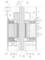
- FIG. 3 is an enlarged schematic view of the main part of Fig. 2.
- the upper balance weight 37, together with the motor 20, is disposed between the height of the discharge pipe 17 and the height of the support member 77.
- the stator 21 of the motor 20 has a stator core 22, an upper insulator 23a, a lower insulator 23b, and multiple coils 24.
- the stator core 22 is formed from multiple laminated steel plates.
- the upper insulator 23a and the lower insulator 23b are both resin parts.
- the upper insulator 23a is disposed on the upper surface of the stator core 22.
- the lower insulator 23b is disposed on the lower surface of the stator core 22.
- the multiple coils 24 are formed by winding a conductor around the stator core 22. The multiple coils 24 use the received power to generate a magnetic field for interacting with the rotor 25.
- the rotor 25 of the motor 20 rotates around the central axis C.
- the rotor 25 has a rotor body 26 and a lower balance weight 27.
- the rotor body 26 has a rotor core 26a, permanent magnets 26b, and end plates 26c.
- the rotor core 26a is made of multiple laminated steel plates.
- the permanent magnets 26b are installed in a space provided inside the rotor core 26a.
- the end plates 26c are provided on the upper and lower surfaces of the rotor core 26a. The end plates 26c prevent the permanent magnets from falling out of the space in the rotor core 26a.
- the lower balance weight 27 is installed on the underside of the rotor body 26. Like the upper balance weight 37, the lower balance weight 27 is intended to balance the crankshaft 30. The lower balance weight 27 is in contact with the end plate 26c.
- the rotating member 60 rotates together with the rotor 25.
- the rotating member 60 is fixed to the lower balance weight 27.
- the rotor 25 is formed with a rotor refrigerant passage 51 that penetrates the rotor 25 in the axial direction of the compressor 100.
- the rotor refrigerant passage 51 is sometimes called an "air hole.”
- the rotor refrigerant passage 51 allows the refrigerant R to pass from the second space S2 to the first space S1.
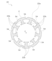
- FIG. 4 is a plan view of the stator core 22.
- the stator core 22 has an annular portion 22a.
- the annular portion 22a has a circular shape centered on the central axis C.
- a plurality of recesses are formed on the outer periphery E of the annular portion 22a. These recesses are called core cuts 54.
- the core cuts 54 allow the refrigerant R to pass from the first space S1 to the second space S2.
- a plurality of teeth 22b are formed on the inner periphery of the annular portion 22a, protruding toward the center of the annular portion 22a.
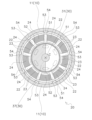
- FIG. 5 is a schematic diagram showing the top view or cross section of the main parts of the compressor 100.
- the motor 20 is shown in a plan view.
- the casing 10 and the crankshaft 30 are shown in cross section.
- Each tooth 22b of the stator core 22 is wound with a winding together with the portion of the insulator 23 that covers each tooth 22b to form a single coil 24.
- a coil gap 53 is formed between adjacent coils 24.
- the coil gap 53 also functions as a passage for the refrigerant R extending in the axial direction of the compressor 100.
- the coil gap 53 allows the refrigerant R to pass from the second space S2 to the first space S1.
- a gap called an air gap 52 is formed between the stator 21 and the rotor 25.
- the air gap 52 also functions as a passage for the refrigerant R extending in the axial direction of the compressor 100.
- An air gap is formed between the stator and the rotor. The air gap 52 allows the refrigerant R to pass from the second space S2 to the first space S1.
- the rotor refrigerant passage 51 of the rotor 25 also functions as a passage for the refrigerant R extending in the axial direction of the compressor 100.
- Figure 6 shows the underside of the rotating member 60.
- the rotating member 60 is fixed to the lower balance weight 27.
- the rotating member 60 has three mounting openings 67.
- the mounting openings 67 are for fasteners to pass through in order to fix the rotating member 60 to the lower balance weight 27.
- the rotating member 60 has a number of grooves 67.
- the multiple grooves 67 extend radially from the central axis C toward the periphery P.
- the rotor refrigerant passage 51, the air gap 52, and the coil gap 53 all allow the refrigerant R to pass from below to above when the compressor 100 compresses the refrigerant R.
- the rotor refrigerant passage 51, the air gap 52, and the coil gap 53 all allow the refrigerant R to pass from below to above the motor 20, and are therefore collectively referred to as the refrigerant ascending passage 50.
- the core cut 54 allows the refrigerant R to pass from above to below, as shown by the thick arrow, and can therefore also be referred to as the refrigerant descending passage.
- FIG. 7 Structure around the rotating member 60
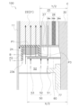
- Fig. 7 is an enlarged schematic diagram of the main part of Fig. 3.
- the lower insulator 23b has a base P1, an outer circumferential wall P2, and an inner circumferential wall P3.
- the base P1 is an annular portion that contacts the stator core 22.
- the outer circumferential wall P2 extends downward from near the outer periphery of the base P1.
- the inner circumferential wall P3 extends downward from near the inner periphery of the base P1.
- the rotating member 60 is fixed to the lower balance weight 27.
- the rotating member 60 is indirectly fixed to the rotor body 26 via the lower balance weight 27.
- the lower balance weight 27 is fixed to the end plate 26c of the rotor body 26.
- the rotating member 60 rotates together with the crankshaft 30, the rotor body 26, and the lower balance weight 27.
- the rotating member 60 is positioned lower than the lower end B of the coil 24.
- the height difference between the rotating member 60 and the lower end of the coil 24 is, for example, 20 mm or less, and preferably 15 mm or less.
- the outer diameter X of the rotating member 60 is larger than the inner diameter Y of the stator 21.
- the rotating member 60 covers the refrigerant inlet below the refrigerant ascending passage 50. Note that in FIG. 7, only half of the outer diameter X and inner diameter Y are shown, and are indicated as (X/2) and (Y/2), respectively.
- the rotating member 60 is positioned higher than the lower end T of the outer peripheral wall P2 of the lower insulator 23b.
- Figure 8 is a cross-sectional view of the rotating member 60.
- a groove 67 provided on the underside of the rotating member 60 has an inner wall 68.
- the refrigerant R flows in the circumferential direction of the rotating member 60 while moving radially outward of the rotating member 60 as a whole. Some of the refrigerant R flows around the groove 67 and creates a vortex, and the oil mist in the refrigerant R collides with the inner wall 68 located on the opposite end from the direction of travel of the refrigerant R and other points.
- the lubricating oil L contained in the refrigerant R is also absorbed into an oil film on the inner wall 68 of the groove 67.
- the lubricating oil L that constitutes the oil film on the underside of the rotating member 60 moves in a spiral motion across the surface of the rotating member 60 from the center of the rotating member 60 radially outward due to its own viscosity and the action of centrifugal force.
- the lubricating oil L that constitutes the oil film on the inner wall 68 moves radially outward along the groove 67.
- the lubricating oil L then splashes out radially from the outer periphery of the rotating member 60.
- the lubricating oil L then collides with the casing 10 and other components, and falls into the oil reservoir 14.
- the rotating member 60 is located between the discharge pipe 17 and the oil reservoir 14. Therefore, the refrigerant R rising from the oil reservoir 14 to the discharge pipe 17 collides with the rotating member 60 which functions as an obstacle to the refrigerant R, so that the lubricating oil L contained in the refrigerant R is separated, and thus the discharge of the lubricating oil L from the compressor 100 is suppressed.
- the rotating member 60 is disposed close to the lower end of the coil 24, so that the height difference between the rotating member 60 and the lower end of the coil 24 is 20 mm or less, or preferably 15 mm or less. Therefore, the rotating member 60 can function as an obstacle to the refrigerant R.
- the rotating member 60 is indirectly fixed to the rotor body 26. Therefore, the rotating member 60 can block the center of the upward flow of the refrigerant.
- the rotor 25 has a lower balance weight 27. Therefore, vibrations of the rotor 25 during rotation can be suppressed.
- the rotating member 60 is fixed to the lower balance weight 27. Therefore, the rotating member 60 is fixed to the rotor body 26 via the lower balance weight 27.
- the compressor 100 has a rotating member 60 that functions as an obstacle to the refrigerant R. Therefore, in the refrigerant circuit of the refrigeration device 101, discharge of the lubricating oil L from the compressor 100 is suppressed.
- the rotating member 60 is fixed to the crankshaft 30. Therefore, the rotating member 60 can block the upward flow of the refrigerant near the crankshaft 30.
- the compressor 100 according to the first embodiment described above is a scroll compressor.
- the compressor 100 may be a compressor other than a scroll compressor.
- the compressor 100 may be a rotary compressor or a screw compressor.
- the rotating member 60 is provided with a plurality of grooves 67.
- the rotating member 60 may be provided with only one groove 67 extending radially from the central axis C toward the circumferential edge P.
- the rotating member 60 may not be provided with the groove 67.
- the lower balance weight 27 has an arc shape as shown in Fig. 6.
- the lower balance weight 27 may have a semicircular shape as shown in Fig. 9.
- Fig. 9 shows the underside of the rotor 25.
- the lower balance weight 27 has a semicircular weight portion 27a, two legs 27b extending in the radial direction, and an annular portion 27c connecting the weight portion 27 and the legs 27b.
- Second Embodiment (1) Configuration Fig. 10 is an enlarged schematic view of a compressor 100 according to a second embodiment.
- the compressor 100 according to this embodiment differs from the first embodiment in the structure of the rotating member 60.
- the rotating member 60 according to this embodiment differs from the rotating member 60 of the first embodiment in that it has a first opening 61 and a second opening 62.
- FIG. 11 is a plan view of the rotating member 60 according to this embodiment. This figure also shows the position of the lower balance weight 27 that is fixed to the rotating member 60.
- the shape of the rotating balance weight 27 is the same as that of the modified example of the first embodiment shown in FIG. 7.
- the rotating member 60 has four first openings 61, eight second openings 62, and five mounting openings 67.
- the mounting openings 67 are for fasteners to pass through in order to fix the rotating member 60 to the lower balance weight 27.
- the outer region Q of the rotating member 60 is sandwiched between the periphery P and the second openings 62.
- the first opening 61 is configured to communicate with the rotor refrigerant passage 51.
- the second opening 62 is configured to communicate with the air gap 52.
- the outer region Q has the function of at least partially blocking the upward flow of the refrigerant attempting to pass through the coil gap 53.
- Rotating member 60 has first opening 61 or second opening 62. Therefore, a portion of the upward flow of refrigerant R can pass through either rotor refrigerant passage 51, air gap 52, or coil gap 53 after passing through first opening 61 or second opening 62, so that a necessary amount of upward flow of refrigerant R can be secured.
- the rotating member 60 is indirectly fixed to the rotor body 26 via the lower balance weight 27.
- the rotating member 60 may be directly fixed to the rotor body 26.
- the rotating member 60 passes through the first opening 61 or the second opening 62, so that the upward refrigerant flow can reach the rotor refrigerant passage 51 or the air gap 52.
Landscapes
- Engineering & Computer Science (AREA)
- Mechanical Engineering (AREA)
- General Engineering & Computer Science (AREA)
- Physics & Mathematics (AREA)
- Thermal Sciences (AREA)
- Applications Or Details Of Rotary Compressors (AREA)
- Compressor (AREA)
Abstract
Description
(1)冷凍装置101の構成
図1は、第1実施形態に係る冷凍装置101の構成を示す。冷凍装置101は、熱源ユニット90、利用ユニット80、及び連絡配管群85を有する。
図2は、圧縮機100の構成を示す。圧縮機100はスクロール圧縮機であり、ケーシング10、モータ20、クランクシャフト30、圧縮機構40、仕切部材70、支持部材77、を有する。
ケーシング10は、互いに気密的に接合された胴部11、上蓋部12、及び下蓋部13を有する。
モータ20は、内部空間Sの中に配置される。モータ20は、圧縮機100の外部から供給される電力を利用して、圧縮機構40を駆動するための動力を生成する。モータ20は、ステータ21及びロータ25を有する。ステータ21及びロータ25は、共通の中心軸Cを有する円柱状又は円筒状である。ステータ21は胴部11に固定されている。ロータ25は、ステータ21の中心部の空洞に配置され、回転可能に支持されている。
クランクシャフト30は、モータ20が生成した動力を圧縮機構40へ伝達する。クランクシャフト30は、主軸部31と、主軸部31に対して偏心した偏心部32と、上部バランスウェイト37とを有する。主軸部31は、ステータ21及びロータ25と中心軸Cを共有する。
圧縮機構40は、内部空間Sの中かつモータ20の上方に配置される。圧縮機構40は、クランクシャフト30の回転によって伝達された動力を利用して、低圧ガス冷媒を圧縮することによって高圧ガス冷媒を生成する。圧縮機構40は、固定スクロール41と可動スクロール42を有する。固定スクロール41は、仕切部材70に支持されている。可動スクロール42は、ボス46を有する。ボス46の凹部には、クランクシャフト30の偏心部32がはめ込まれている。偏心部32は、多くの場合にはすべり軸受を介してボス46の凹部の内面と接触する。クランクシャフト30の回転はボス46に伝達され、それによって可動スクロール42が固定スクロール41に対して公転する。
仕切部材70は、胴部11に取り付けられている。仕切部材70は、第3空間S3と第1空間S1を隔てている。仕切部材70は、主軸部31の上部を、多くの場合にはすべり軸受を介して支持する。
引き続き図2を参照して、冷媒Rと潤滑油Lの移動を説明する。
図3は、図2の要部を拡大した模式図である。上部バランスウェイト37は、モータ20とともに、吐出管17の高さと支持部材77の高さの間に配置されている。
図7は、図3の要部を拡大した模式図である。下部インシュレータ23bは、基部P1、外周壁P2、内周壁P3を有する。基部P1はステータコア22と接触する円環状の部位である。外周壁P2は、基部P1の外周の付近から下方へ延びる。内周壁P3は、基部P1の内周の付近から下方へ延びる。
(6-1)
吐出管17と油溜まり14の間に回転部材60が位置する。したがって、油溜まり14から吐出管17へ上昇する冷媒Rは、冷媒Rに対する障害物として機能する回転部材60に衝突するので、冷媒Rに含まれる潤滑油Lが分離され、ひいては圧縮機100からの潤滑油Lの排出が抑制される。
回転部材60がコイル24の下方に配置される。したがって、油溜まり14からコイル隙間53へ上昇しようとする冷媒Rは、回転部材60に衝突するので、冷媒Rに含まれる潤滑油Lが分離される。上昇する冷媒流が通過する面積のうち、コイル隙間53の断面積が占める割合は大きいので、潤滑油Lの分離は効率的になる。
回転部材60はコイル24の下端に近接して配置されており、その結果、回転部材60とコイル24の下端との高低差は20mm以下、又は好ましくは15mm以下である。したがって、回転部材60が冷媒Rに対する障害物として機能できる。
コアカット54を通過する冷媒Rの下降流は、回転部材60よりも低く配置されている外周壁P2よりもさらに下方に移動したのち、上昇流に変わる。したがって、冷媒Rの上昇流が回転部材60に衝突しやすい。
冷媒Rが回転部材60の付近を移動するとき、冷媒Rの一部は溝69の中を流れて溝69の内壁68に衝突する。この衝突により、冷媒Rに含まれている潤滑油Lが、既に溝69の内壁68に付着している油膜に吸収される場合がある。したがって、冷媒Rに含まれる潤滑油Lが効率的に冷媒Rから分離される。
冷媒Rの上昇流は、ロータ冷媒通路51、エアギャップ52、及び、コイル隙間53を通過する。回転部材60は、平面視において、ロータ冷媒通路51の全部、エアギャップ52の全部、及びコイル隙間53の少なくとも一部をさえぎる。したがって、冷媒Rの上昇流のうちの多くの割合が回転部材60と衝突する。
回転部材60は、ロータ本体26に間接的に固定される。したがって、冷媒上昇流の中心部を回転部材60はさえぎることができる。
ロータ25は下部バランスウェイト27を有する。したがって、ロータ25の回転時の振動を抑制できる。
回転部材60が、下部バランスウェイト27に固定される。したがって、回転部材60は下部バランスウェイト27を介してロータ本体26に固定される。
圧縮機100が、冷媒Rに対する障害物として機能する回転部材60を有する。したがって、冷凍装置101の冷媒回路において、圧縮機100から潤滑油Lが排出されることが抑制される。
(7-1)
上述の第1実施形態に係る圧縮機100において、回転部材60は、下部バランスウェイト27を介してロータ本体26に間接的に固定されている。これに代えて、回転部材60は、クランクシャフト30に固定されていてもよい。
上述の第1実施形態に係る圧縮機100は、スクロール圧縮機である。これに代えて、圧縮機100は、スクロール圧縮機以外の圧縮機であってよい。例えば、圧縮機100は、ロータリー圧縮機、又はスクリュー圧縮機であってよい。
上述の第1実施形態に係る圧縮機100において、回転部材60には、複数の溝67が設けられている。これに代えて、回転部材60には中心軸Cから周縁Pに向かって径方向に延びる1本の溝67のみが設けられていてもよい。あるいは、回転部材60には溝67が設けられていなくともよい。
上述の第1実施形態に係る圧縮機100において、下部バランスウェイト27は、図6に示すように円弧形状を有している。これに代えて、下部バランスウェイト27は、図9に示すように、半円形状を有していてもよい。図9はロータ25の下面を示している。下側バランスウェイト27は、半円状のウェイト部27aと、径方向に延びる2つの脚部27bと、ウェイト部27及び脚部27bを接続する環状部27cを有している。
(1)構成
図10は、第2実施形態に係る圧縮機100を拡大した模式図である。本実施形態に係る圧縮機100は、回転部材60の構造が第1実施形態とは異なる。本実施形態に係る回転部材60は、第1開口61及び第2開口62を有する点において、第1実施形態の回転部材60とは相違している。
回転部材60は第1開口61又は第2開口62を有する。したがって、冷媒Rの上昇流の一部は第1開口61又は第2開口62を通過したのちにロータ冷媒通路51、エアギャップ52、及び、コイル隙間53のいずれかを通過できるので、冷媒Rの上昇流の必要量を確保できる。
(3-1)
第1開口61、第2開口62、及び取付開口67の個数は、図11に示されている構成に限定される必要はない。回転部材60は、第1開口61及び第2開口62のうちのいずれか一方のみを有していてもよい。
上述の第2実施形態に係る圧縮機100において、回転部材60は、下部バランスウェイト27を介してロータ本体26に間接的に固定されている。これに代えて、回転部材60は、ロータ本体26に直接的に固定されていてもよい。回転部材60が第1開口61又は第2開口62を通過することによって、冷媒上昇流はロータ冷媒通路51又はエアギャップ52へ到達することができる。
第1実施形態又はその変形例として開示されている構成の一部を、本実施形態に適用してもよい。
以上、本開示の実施形態を説明したが、請求の範囲に記載された本開示の趣旨及び範囲から逸脱することなく、形態や詳細の多様な変更が可能なことが理解されるであろう。
14 :油溜まり
15 :吸入管
17 :吐出管
20 :モータ
21 :ステータ
22 :ステータコア
23a :上部インシュレータ
23b :下部インシュレータ
24 :コイル
25 :ロータ
26 :ロータ本体
26a :ロータコア
26b :永久磁石
26c :端板
27 :下部バランスウェイト
30 :クランクシャフト
37 :上部バランスウェイト
40 :圧縮機構
50 :冷媒上昇通路
51 :ロータ冷媒通路
52 :エアギャップ
53 :コイル隙間
54 :コアカット(冷媒下降通路)
60 :回転部材
61 :第1開口
62 :第2開口
69 :溝
80 :利用ユニット
90 :熱源ユニット
100 :圧縮機
101 :冷凍装置
B :コイル下端(下端)
E :ステータコア外周(外周)
L :潤滑油
P1 :基部
P2 :外周壁
P3 :内周壁
R :冷媒
S :内部空間
S1 :第1空間
S2 :第2空間
S3 :第3空間
T :外周壁下端(下端)
X :回転部材外径(外径)
Y :ステータ内径(内径)
Claims (12)
- 内部空間(S)を有するケーシング(10)と、
円筒状のステータ(21)、前記ステータの中に配置されるロータ(25)、冷媒下降通路(54)、及び冷媒上昇通路(50)を有し、前記内部空間の中に配置されるモータ(20)と、
前記内部空間の中かつ前記モータの上方に配置され、前記モータとの間に第1空間(S1)を形成し、かつ、冷媒(R)を圧縮する圧縮機構(40)と、
前記内部空間の中かつ前記モータの下方に配置され、かつ、前記モータとの間に第2空間(S2)を形成する油溜まり(14)と、
前記ロータの回転を前記圧縮機構へ伝達するクランクシャフト(30)と、
前記第2空間に配置され、前記ロータとともに回転し、かつ、前記ステータの内径(Y)よりも大きい外径(X)を有する回転部材(60)と、
前記第1空間に配置される吐出管(17)と、
を備え、
前記冷媒下降通路は、前記冷媒を前記第1空間から前記第2空間へ通過させ、
前記冷媒上昇通路は、前記冷媒を前記第2空間から前記第1空間へ通過させる、
圧縮機(100)。 - 前記ステータは、ステータコア(22)、及び、前記ステータコアに導線を巻き付けることによって形成されるコイル(24)、を有し、
前記冷媒下降通路は、前記ステータコアの外周(E)に形成されたコアカット(54)であり、
前記回転部材は、前記コイルの下端(B)よりも低く配置される、
請求項1に記載の圧縮機。 - 前記回転部材と前記コイルの前記下端(B)の高低差は、20mm以下である、
請求項2に記載の圧縮機。 - 前記ステータは、前記ステータコアの下面に配置される円環状の下部インシュレータ(23b)、をさらに有し、
前記下部インシュレータは、前記下部インシュレータの外周の付近から下方へ延びる外周壁(P2)を有し、
前記回転部材は、前記外周壁の下端(T)よりも高く配置される。
請求項2又は請求項3に記載の圧縮機。 - 前記回転部材は、中心から周縁に向かって径方向に延びる溝(67)を有する、
請求項1から4のいずれか1項に記載の圧縮機。 - 前記回転部材は、中心から周縁に向かって径方向に放射状に延びる複数の溝(67)を有する、
請求項1から4のいずれか1項に記載の圧縮機。 - 前記ロータは、前記ロータを軸方向に貫通するロータ冷媒通路(51)を有し、
前記ステータと前記ロータの間には、エアギャップ(52)が形成されており、
前記ステータは、隣接する2つの前記コイル間に位置するコイル隙間(53)を有し、
前記冷媒上昇通路(50)は、前記ロータ冷媒通路(51)、前記エアギャップ(52)、及びコイル隙間(53)を含む、
請求項1から6のいずれか1項に記載の圧縮機。 - 前記ロータは、ロータ本体、及び、前記ロータ本体の下面に設けられた下部バランスウェイト(27)を有し、
前記回転部材は、前記下部バランスウェイトに固定される、
請求項1から7のいずれか1項に記載の圧縮機。 - 前記ロータは、ロータ本体、及び、前記ロータ本体の下面に設けられた下部バランスウェイト(27)、を有し、
前記回転部材は、前記ロータ本体に固定される、
請求項1から7のいずれか1項に記載の圧縮機。 - 前記回転部材は、前記クランクシャフトに固定される、
請求項1から7のいずれか1項に記載の圧縮機。 - 前記回転部材は、前記ロータ冷媒通路に連通する第1開口(61)、及び、前記エアギャップに連通する第2開口(62)、のうちの少なくとも1つを有する、
請求項1から10のいずれか1項に記載の圧縮機。 - 請求項1から11のいずれか1項に記載の圧縮機、
を備える、冷凍装置(101)。
Priority Applications (3)
| Application Number | Priority Date | Filing Date | Title |
|---|---|---|---|
| EP24823150.8A EP4729782A1 (en) | 2023-06-13 | 2024-05-13 | Compressor and refrigeration device |
| CN202480038167.9A CN121285695A (zh) | 2023-06-13 | 2024-05-13 | 压缩机和制冷装置 |
| US19/398,294 US20260104047A1 (en) | 2023-06-13 | 2025-11-24 | Compressor and refrigeration apparatus |
Applications Claiming Priority (2)
| Application Number | Priority Date | Filing Date | Title |
|---|---|---|---|
| JP2023-096940 | 2023-06-13 | ||
| JP2023096940 | 2023-06-13 |
Related Child Applications (1)
| Application Number | Title | Priority Date | Filing Date |
|---|---|---|---|
| US19/398,294 Continuation US20260104047A1 (en) | 2023-06-13 | 2025-11-24 | Compressor and refrigeration apparatus |
Publications (1)
| Publication Number | Publication Date |
|---|---|
| WO2024257528A1 true WO2024257528A1 (ja) | 2024-12-19 |
Family
ID=93793924
Family Applications (1)
| Application Number | Title | Priority Date | Filing Date |
|---|---|---|---|
| PCT/JP2024/017699 Ceased WO2024257528A1 (ja) | 2023-06-13 | 2024-05-13 | 圧縮機及び冷凍装置 |
Country Status (5)
| Country | Link |
|---|---|
| US (1) | US20260104047A1 (ja) |
| EP (1) | EP4729782A1 (ja) |
| JP (1) | JP7598080B1 (ja) |
| CN (1) | CN121285695A (ja) |
| WO (1) | WO2024257528A1 (ja) |
Citations (3)
| Publication number | Priority date | Publication date | Assignee | Title |
|---|---|---|---|---|
| JP2012202253A (ja) * | 2011-03-24 | 2012-10-22 | Sanyo Electric Co Ltd | スクロール圧縮装置 |
| JP2018021483A (ja) * | 2016-08-02 | 2018-02-08 | 日立ジョンソンコントロールズ空調株式会社 | 密閉型スクロール圧縮機 |
| JP2021017849A (ja) | 2019-07-19 | 2021-02-15 | ダイキン工業株式会社 | 圧縮機 |
-
2024
- 2024-05-13 CN CN202480038167.9A patent/CN121285695A/zh active Pending
- 2024-05-13 WO PCT/JP2024/017699 patent/WO2024257528A1/ja not_active Ceased
- 2024-05-13 JP JP2024078201A patent/JP7598080B1/ja active Active
- 2024-05-13 EP EP24823150.8A patent/EP4729782A1/en active Pending
-
2025
- 2025-11-24 US US19/398,294 patent/US20260104047A1/en active Pending
Patent Citations (3)
| Publication number | Priority date | Publication date | Assignee | Title |
|---|---|---|---|---|
| JP2012202253A (ja) * | 2011-03-24 | 2012-10-22 | Sanyo Electric Co Ltd | スクロール圧縮装置 |
| JP2018021483A (ja) * | 2016-08-02 | 2018-02-08 | 日立ジョンソンコントロールズ空調株式会社 | 密閉型スクロール圧縮機 |
| JP2021017849A (ja) | 2019-07-19 | 2021-02-15 | ダイキン工業株式会社 | 圧縮機 |
Also Published As
| Publication number | Publication date |
|---|---|
| JP2024178905A (ja) | 2024-12-25 |
| US20260104047A1 (en) | 2026-04-16 |
| JP7598080B1 (ja) | 2024-12-11 |
| EP4729782A1 (en) | 2026-04-22 |
| CN121285695A (zh) | 2026-01-06 |
Similar Documents
| Publication | Publication Date | Title |
|---|---|---|
| US10890186B2 (en) | Compressor | |
| US6860724B2 (en) | Rotary compressor | |
| JP4143827B2 (ja) | スクロール圧縮機 | |
| US12025133B2 (en) | Compressor and air-conditioner | |
| WO2011033710A1 (ja) | 多段圧縮機 | |
| WO2022224420A1 (ja) | 圧縮機および冷凍サイクル装置 | |
| CN110662902B (zh) | 密封制冷压缩机及制冷装置 | |
| EP3163083B1 (en) | Electric compressor | |
| JP7632326B2 (ja) | スクロール型電動圧縮機 | |
| JP7598080B1 (ja) | 圧縮機及び冷凍装置 | |
| JP2007518911A (ja) | 圧縮機 | |
| CN103452844B (zh) | 旋转压缩机 | |
| JP6745913B2 (ja) | 圧縮機 | |
| JP7518394B2 (ja) | 圧縮機および冷凍装置 | |
| WO2005028869A1 (en) | Rotational motor and electric compressor | |
| US11168687B2 (en) | Scroll compressor | |
| JP2020186651A (ja) | 空調用圧縮機 | |
| JP7454477B2 (ja) | 圧縮機及び空気調和機 | |
| JP2024146085A (ja) | 圧縮機及び冷凍装置 | |
| CN114450488B (zh) | 压缩机以及空调机 | |
| JP6729159B2 (ja) | スクロールコンプレッサ | |
| JP2024065478A (ja) | スクロール圧縮機 | |
| WO2024116308A1 (ja) | 圧縮機、冷凍サイクル装置 | |
| KR100447206B1 (ko) | 아우터 로터형 전동기가 구비된 스크롤 압축기 | |
| US20260117773A1 (en) | Compressor and refrigeration apparatus |
Legal Events
| Date | Code | Title | Description |
|---|---|---|---|
| 121 | Ep: the epo has been informed by wipo that ep was designated in this application |
Ref document number: 24823150 Country of ref document: EP Kind code of ref document: A1 |
|
| WWE | Wipo information: entry into national phase |
Ref document number: 2024823150 Country of ref document: EP |
|
| NENP | Non-entry into the national phase |
Ref country code: DE |
|
| ENP | Entry into the national phase |
Ref document number: 2024823150 Country of ref document: EP Effective date: 20260113 |
|
| ENP | Entry into the national phase |
Ref document number: 2024823150 Country of ref document: EP Effective date: 20260113 |
|
| ENP | Entry into the national phase |
Ref document number: 2024823150 Country of ref document: EP Effective date: 20260113 |
|
| WWP | Wipo information: published in national office |
Ref document number: 2024823150 Country of ref document: EP |