WO2024257432A1 - 試料搬送システム、試料搬送キャリア、および試料容器の搬送方法 - Google Patents
試料搬送システム、試料搬送キャリア、および試料容器の搬送方法 Download PDFInfo
- Publication number
- WO2024257432A1 WO2024257432A1 PCT/JP2024/012382 JP2024012382W WO2024257432A1 WO 2024257432 A1 WO2024257432 A1 WO 2024257432A1 JP 2024012382 W JP2024012382 W JP 2024012382W WO 2024257432 A1 WO2024257432 A1 WO 2024257432A1
- Authority
- WO
- WIPO (PCT)
- Prior art keywords
- sample transport
- sample
- carrier
- transport carrier
- plane
- Prior art date
- Legal status (The legal status is an assumption and is not a legal conclusion. Google has not performed a legal analysis and makes no representation as to the accuracy of the status listed.)
- Ceased
Links
Images





Classifications
-
- B—PERFORMING OPERATIONS; TRANSPORTING
- B65—CONVEYING; PACKING; STORING; HANDLING THIN OR FILAMENTARY MATERIAL
- B65G—TRANSPORT OR STORAGE DEVICES, e.g. CONVEYORS FOR LOADING OR TIPPING, SHOP CONVEYOR SYSTEMS OR PNEUMATIC TUBE CONVEYORS
- B65G54/00—Non-mechanical conveyors not otherwise provided for
- B65G54/02—Non-mechanical conveyors not otherwise provided for electrostatic, electric, or magnetic
-
- G—PHYSICS
- G01—MEASURING; TESTING
- G01N—INVESTIGATING OR ANALYSING MATERIALS BY DETERMINING THEIR CHEMICAL OR PHYSICAL PROPERTIES
- G01N35/00—Automatic analysis not limited to methods or materials provided for in any single one of groups G01N1/00 - G01N33/00; Handling materials therefor
- G01N35/02—Automatic analysis not limited to methods or materials provided for in any single one of groups G01N1/00 - G01N33/00; Handling materials therefor using a plurality of sample containers moved by a conveyor system past one or more treatment or analysis stations
- G01N35/04—Details of the conveyor system
Definitions
- the present invention relates to a sample transport system that is connected to an automatic analyzer that performs clinical tests, etc., a sample transport carrier that is suitable for the sample transport system, and a method for transporting sample containers.
- Patent Document 1 describes a laboratory sample delivery system that includes several container carriers, each of which is equipped with at least one magnetically active device, preferably at least one permanent magnet, and adapted to transport sample containers, a transport plane adapted to transport the container carriers, and several electromagnetic actuators stationarily positioned below the transport plane, the electromagnetic actuators adapted to move the container carriers above the transport plane by applying a magnetic force to the container carriers.
- samples such as blood, plasma, serum, urine, and other bodily fluids
- samples are usually stored in containers such as blood collection tubes and loaded onto a dedicated sample transport carrier.
- This sample transport carrier is transported to the desired automated analyzer by the sample transport unit of the sample transport system, allowing efficient analysis.
- Patent Document 1 proposes a sample transport system in which the sample transport section of the sample transport system is configured with a sample transport plane, and a number of electromagnetic coils are arranged directly below the sample transport plane.
- a sample transport carrier with a permanent magnet built into its bottom surface is used, and the excitation state of the electromagnetic coil is controlled to apply a magnetic force to the permanent magnet of the sample transport carrier, causing the sample transport carrier to move in any direction on the sample transport plane.
- the object of the present invention is to provide a flexible, inexpensive, and simple sample transport system, as well as a sample transport carrier and a method for transporting sample containers that realize the system.
- the present invention includes multiple means for solving the above problems, and one example is a sample transport carrier that carries a sample container containing a sample, a sample transport plane along which the sample transport carrier can move, and a plurality of permanent magnets arranged on the underside of the sample transport plane along the movement path of the sample transport carrier, the sample transport carrier having three or more electromagnetic coils arranged in a line in the transport direction of the sample transport carrier, a power supply unit that supplies power to the electromagnetic coils and the control unit, and a control unit that controls the excitation state of the electromagnetic coils, and the sample transport carrier moves on the upper surface of the sample transport plane by controlling the excitation state of the electromagnetic coils to apply a magnetic force to the permanent magnets.
- the present invention provides a flexible, inexpensive, and simple sample transport system, a sample transport carrier, and a method for transporting a sample container. Problems, configurations, and effects other than those described above will become clear from the description of the embodiments below.
- 1 is a diagram showing the appearance of a sample transport plane and a sample transport carrier which constitute a sample transport system according to an embodiment of the present invention
- 1 is a cross-sectional view showing the internal structure of a sample transport carrier and a transport panel that constitutes a sample transport plane in the sample transport system of the embodiment.
- 11A and 11B are diagrams showing examples of the shape of a contact portion between a sample transport carrier and a sample transport plane in the sample transport system of the embodiment
- 13A and 13B are diagrams showing other examples of the shape of the contact portion between the sample transport carrier and the sample transport plane in the sample transport system of the embodiment.
- 1 is a diagram showing the positional relationship between an electromagnetic coil of a sample transport carrier and a permanent magnet in a transport panel in the sample transport system of the embodiment.
- FIG. 1 is a diagram showing the arrangement of electromagnetic coils in a sample transport carrier and the arrangement of permanent magnets in a transport panel in a sample transport system of an embodiment.
- 11A and 11B are diagrams showing an example of the arrangement of permanent magnets on a transport panel and the shape of a yoke in the sample transport system of the embodiment.
- FIG. 6 is a diagram showing the relationship between the excitation state of the test electromagnetic coil in FIG. 5 and the output value of a sensor unit that detects the strength of the magnetic force of the permanent magnet.
- 13 is a diagram showing another example of the arrangement of electromagnetic coils in the sample transport carrier and the arrangement of permanent magnets in the transport panel in the sample transport system of the embodiment.
- FIG. 1 is a diagram showing the arrangement of an RFID tag and a wireless power feed coil constituting a wireless power feeder in a sample transport system according to an embodiment.
- FIG. 1 is a top view showing the positional relationship when a sample transport carrier communicates with an RFID tag in a sample transport system according to an embodiment.
- FIG. 1 is a side view showing the positional relationship when a sample transport carrier communicates with an RFID tag in a sample transport system according to an embodiment of the present invention.
- FIG. 4 is a conceptual diagram showing communication between a sample transport carrier and an external control unit in the sample transport system of the embodiment, and a communication state between the sample transport carriers.
- FIG. 1 is a top view showing a positional relationship when a sample transport carrier receives power from a wireless power feeder in a sample transport system according to an embodiment.
- FIG. 1 is a side view showing a positional relationship when a sample transport carrier receives power from a wireless power feeder in a sample transport system according to an embodiment.
- FIG. 1 is a diagram showing an example of a cross section of a connection portion of a transport panel in a sample transport system according to an embodiment of the present invention; 13 is a diagram showing the relationship between the center of gravity of a sample transport carrier and the cross-sectional shape of an inclined surface provided at the end of a transport panel when the sample transport carrier passes over the inclined surface at the end in the sample transport system of the embodiment.
- FIG. 1 is a top view showing a positional relationship when a sample transport carrier receives power from a wireless power feeder in a sample transport system according to an embodiment.
- FIG. 1 is a side view showing a positional relationship when a sample transport carrier receives power from
- Figure 1 shows the external appearance of the sample transport plane 1 and sample transport carrier 4 that make up the sample transport system of the present invention.
- the sample transport system is a system for transporting sample transport carriers 4 carrying containers 3 containing samples, and includes a sample transport plane 1 constructed by connecting multiple transport panels 2 arranged horizontally. By arbitrarily connecting the transport panels 2, it is possible to construct any sample transport plane 1, and the movement range of the sample transport carrier 4 can be flexibly set.
- the sample transport carrier 4 is transported to the desired position by moving on the sample transport plane 1.
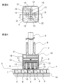
- FIG. 2 is a cross-sectional view of the sample transport carrier and the transport panel, with "Cross Section A” showing the cross section A-A at "Cross Section B" in Figure 2 and "Cross Section B” showing the cross section B-B at "Cross Section A”.
- each transport panel 2 that constitutes the sample transport plane 1 has multiple permanent magnets 6 that form the movement path of the sample transport carrier 4 arranged directly below the top plate 5 along which the sample transport carrier 4 moves, and these multiple permanent magnets 6 are fixed by permanent magnet support members 7.
- the permanent magnets 6 are arranged with alternating north and south poles, and are coupled with a yoke 14 to form a magnetic circuit.
- the sample transport carrier 4 includes a yoke 8, a blood collection tube mounting section 9, a cover 10, an electromagnetic coil 12, an iron core 13, a sensor section 15, a control section 16, a storage battery 17, etc.
- the blood collection tube installation section 9 is a space for installing a container 3 containing a sample at the top, and its outer periphery is covered with a cover 10 made of plastic or the like.
- Each electromagnetic coil 12 is built into the sample transport carrier 4.
- the iron core 13 of each electromagnetic coil 12 is coupled to the yoke 8 to form a magnetic circuit.
- At least three of these electromagnetic coils 12 are arranged side by side in the transport direction of the sample transport carrier 4. In the embodiment shown in Figure 2, five are provided, and are arranged to accommodate movement in two or more different directions as shown in Figures 3, 4, and 5.
- the sensor unit 15 is located near the bottom surface of the sample transport carrier 4, at a position sandwiched between the electromagnetic coils 12, and can grasp the relative position with respect to the permanent magnet 6 by detecting the magnetic force of the permanent magnet 6 inside the transport panel 2.
- a linear Hall sensor can be used for the sensor unit 15.
- the control unit 16 is configured, for example, by a microcomputer, and by appropriately controlling the excitation of the electromagnetic coil 12, a magnetic force acts on the permanent magnet 6, and the sample transport carrier 4 moves on the upper surface of the sample transport plane 1. This control unit 16 controls the excitation state of the electromagnetic coil 12 based on the relative position of the permanent magnet 6 detected by the sensor unit 15.
- the storage battery 17 is a component capable of storing electricity internally and supplies power to the electromagnetic coil 12, the control unit 16, the sensor unit 15, etc., and is composed of, for example, a lithium-ion battery.
- the bottom surface of the sample transport carrier 4 can be equipped with a rolling mechanism such as wheels, but this is not necessary. If no rolling mechanism is provided, the sample transport carrier 4 will have a very simple external shape, sliding along the sample transport plane. Furthermore, since there is no rolling mechanism, no problems resulting from this can be avoided, and a highly reliable sample transport carrier 4 can be constructed. In contrast, if a rolling mechanism is provided, the friction between the bottom surface of the sample transport carrier 4 and the top plate 5 of the transport panel 2 can be made very small, and the force required for transport (excitation current value of the electromagnetic coil 12) can be reduced.
- a rolling mechanism such as wheels
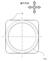
- Figures 3 and 4 show examples of the shape of the contact bottom surface of the sample transport carrier 4, which is the contact surface with the sample transport plane 1, in the case of a sample transport carrier 4 that does not have a rolling mechanism such as wheels.
- the shapes 11a, 11b of the contact bottom surfaces between the sample transport planes 1 do not need to be the same as the shape of the horizontal cross section of the sample transport carrier 4, and can be different shapes as shown in Figures 3 and 4.
- they can be circular as shown in Figure 3, or a diamond-like shape as shown in Figure 4. Note that they are not limited to the circular shape shown in Figure 3 or the diamond-like shape shown in Figure 4, and can be other shapes.
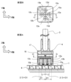
- Figure 5 is a diagram showing the positional relationship between the electromagnetic coil 12 in the sample transport carrier 4 and the permanent magnet 6 in the transport panel 2 when the sample transport carrier 4 moves in the X-axis direction.
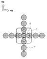
- Figures 6 and 9 are diagrams showing the relationship between the electromagnetic coil 12 and the permanent magnet 6.
- Figure 7 is a diagram showing an example of the arrangement of the permanent magnets 6 on the transport panel 2, and the shape of the yoke 14.
- Figure 8 is a diagram showing the relationship between the excitation states of the electromagnetic coils 12a, 12b, and 12c, and the output values of the sensor units 15a and 15b that detect the strength of the magnetic force of the permanent magnet 6.
- the coils are arranged in combinations that correspond to the movement of the sample transport carrier 4 in two directions, the X axis and the Y axis, and three or more electromagnetic coils 12 are arranged side by side in two perpendicular directions.
- the permanent magnets 6 arranged directly below the sample transport plane 1 are arranged in a square lattice at a constant interval D1 along the movement paths of the sample transport carrier 4 in the X-axis and Y-axis directions.
- the X-axis and Y-axis constituting each square lattice form the movement paths 18a, 18b of the sample transport carrier 4.
- the distance D2 between the intersections of the X-axis and Y-axis of the permanent magnet 6 be an arbitrary integer N times the distance D1.
- sample transport carrier 4 needs to incorporate many parts inside, such as the electromagnetic coil 12, a cross-sectional shape that increases the internal volume is preferable.
- the movement path of the sample transport carrier 4 is formed in a square lattice shape as shown in Figures 6 and 7, considering that the sample transport carriers 4 always maintain the same direction in the X-axis and Y-axis directions regardless of whether they are moving or stopped, it is advantageous for the cross-sectional shape to be square, which reduces the chance of interference between moving sample transport carriers 4 and increases the internal volume of the sample transport carrier 4.
- a sample transport carrier 4 with a square cross-section moves with each side remaining parallel to the X-axis and Y-axis of the square lattice that forms the movement path.
- the spacing between the electromagnetic coils 12 in the X-axis direction of the sample transport carrier 4 can be 2/3 x D1 with respect to the spacing between the permanent magnets 6, D1.
- the spacing between the electromagnetic coils 12 in the Y-axis direction of the sample transport carrier 4 is also 2/3 x D1 with respect to the spacing between the permanent magnets 6, D1.
- the excitation control of the multiple electromagnetic coils 12 in the control unit 16 controls the excitation state of a combination of electromagnetic coils 12 in either the X-axis or Y-axis direction to move them in the X-axis or Y-axis direction, and the principle of movement can be, for example, that of a linear DC motor.
- the detection value of the sensor unit 15 can be used as described above.
- the output values of the sensor units 15a and 15b have a unique combination of output values according to the change in the position of the sample transport carrier 4. Therefore, by checking the output values of each of the sensor units 15a and 15b, the relative positions of the permanent magnet and the sample transport carrier 4 can be ascertained.
- the control unit 16 of the sample transport carrier 4 checks the output values of the sensors 15a and 15b, and determines the relative position of the permanent magnet 6 and the sample transport carrier 4. It also switches the excitation state of the electromagnetic coils 12a, 12b, and 12c as shown in FIG. 8, and moves the sample transport carrier 4 in the X-axis direction.
- Movement in the Y-axis direction is based on the same principle as movement in the X-axis direction.
- the electromagnetic coil 12 in the sample transport carrier 4 and the permanent magnets in the transport panel 2 are arranged in a cross shape in the X-axis and Y-axis directions, so for movement in the Y-axis direction, electromagnetic coils 12d, 12b, and 12e and sensor units 15c and 15d shown in Figure 8 are used.
- the sample transport carrier 4 can be moved in any direction.
- the permanent magnets 6 in the transport panel 2 and the electromagnetic coils 12 in the sample transport carrier 4 can be arranged so that they can move in three directions that are offset by 60 degrees.
- the degree of freedom of the transport path can be increased compared to when they are arranged in a square lattice as shown in FIG. 6.
- FIG. 10 shows the arrangement of the RFID tag 19 arranged along the movement paths 18a, 18b of the sample transport carrier 4, and the wireless power supply coil 20 constituting the wireless power supply unit.
- FIGS. 11 and 12 show the positional relationship of the RFID tag 19 and the components of the RFID reading antenna 21 installed inside the sample transport carrier 4 when the sample transport carrier 4 communicates with the RFID tag 19.
- FIG. 13 is a conceptual diagram showing the communication between the sample transport carrier 4 and the external control unit 28, and the communication state between the sample transport carriers 4.
- multiple RFID tags 19 are provided as non-contact communication units on the sample transport plane 1 along the movement path of the sample transport carrier 4, either directly below the sample transport plane 1 where the movement of the sample transport carrier 4 is not impeded, or on the surface of the sample transport plane 1.
- the sample transport carrier 4 is provided with an RFID reading antenna 21 that communicates with these RFID tags 19.
- an RFID tag 19 is used for the non-contact communication unit, and the component of the communication interface with the RFID tag 19 is an RFID reading antenna 21.
- the RFID tag 19 can be used for various information recording units such as IR communication and barcodes, and the communication interface will adopt a configuration suitable for the specifications of the non-contact communication unit.
- each individual RFID tag 19 has a serial number of the transport panel 2 that identifies the transport panel 2 on which the respective RFID tag 19 is arranged, and position information (unique information) of the RFID tag 19 that indicates the position on the transport panel 2 on which the RFID tag 19 is arranged.
- control unit 16 of the sample transport carrier 4 stores in advance the positional relationship between the serial number of the transport panel 2 and each RFID tag 19. Then, when the sample transport carrier 4 is positioned above the RFID tag 19, it is desirable to identify the transport panel 2 and the RFID tag 19 therein from the unique information received from the RFID tag 19, identify the absolute position of the sample transport carrier 4 within the sample transport plane 1 and the transport panel 2 based on the unique information, and perform excitation control of the electromagnetic coil 12 while checking whether the sample transport carrier 4 has deviated from the path to the destination position during transport.
- sample transport carrier 4 is equipped with a wireless communication unit 29 that performs wireless communication with an external control unit 28 that controls the entire sample transport system, and can perform mutual communication.
- the wireless communication unit 29 also enables mutual communication between sample transport carriers 4.
- sample transport carriers 4 For example, by exchanging information on the position, direction of movement, and operating status between sample transport carriers 4 and determining the priority of the movement of the sample transport carriers 4 based on rules, it is possible for the sample transport carriers 4 to move independently without going through an external control unit 28.
- Figs. 14 and 15 are diagrams showing the positional relationship between the wireless power supply coil 20 constituting the wireless power supply unit and the wireless power receiving coil 22 constituting the wireless power receiving unit of the sample transport carrier 4 when the sample transport carrier 4 receives power from the wireless power supply unit.
- the transport panel 2 is provided with a wireless power supply coil 20 at one specific spot as a charging spot, which serves as a power supply unit for charging the storage battery 17 of the sample transport carrier 4.
- This wireless power supply coil 20 is disposed directly below the sample transport surface of the transport panel 2.
- the sample transport carrier 4 has a wireless power receiving coil 22 on its bottom surface.
- control unit 16 of the sample transport carrier 4 determines that the remaining capacity of the storage battery 17 is low or that there is sufficient transport capacity, the control unit 16 controls the sample transport carrier 4 to transport the sample transport carrier 4 to a position where the wireless power receiving coil 22 overlaps the wireless power supply coil 20, receives power, and charges the storage battery 17 of the sample transport carrier 4.
- the shape of the permanent magnet 6 near where the wireless power supply coil 20 is installed can be changed, and it can be changed from a circular shape like the permanent magnets 6 in other locations to a rectangular shape like the permanent magnets 6a and 6b.
- Figure 16 is a diagram showing a cross section of the connection part of the transport panels 2.
- Figure 17 is a diagram showing the relationship between the center of gravity position 25 of the sample transport carrier 4 and the cross-sectional shape of the inclined surface 24 provided at the end of the transport panel 2 when the sample transport carrier 4 passes over the inclined surface 24 at the end.
- a step 23 may occur between one transport panel 2 and an adjacent transport panel 2, as shown in FIG. 16.
- an inclined surface 24 can be formed at the end of the transport panel 2. It is desirable for this inclined surface 24 to have a gentle slope, so that the sample transport carrier 4 can smoothly overcome any step 23 that may occur.
- the angle between the sample transport plane 1 and the inclined surface 24 is ⁇
- the maximum height of the step between adjacent transport panels 2 is H
- the length of the sample transport carrier 4 in the transport direction is l
- the inclination angle can be made as gentle as possible.
- the sample transport system of this embodiment described above comprises a sample transport carrier 4 carrying a container 3 containing a sample, a sample transport plane 1 on which the sample transport carrier 4 can move, and a plurality of permanent magnets 6 arranged on the underside of the sample transport plane 1 along the movement path of the sample transport carrier 4.
- the sample transport carrier 4 has three or more electromagnetic coils 12 arranged in a line in the transport direction of the sample transport carrier 4, a storage battery 17 that supplies power to the electromagnetic coils 12 and the control unit 16, and a control unit 16 that controls the excitation state of the electromagnetic coils 12.
- the sample transport carrier 4 moves on the upper surface of the sample transport plane 1 by controlling the excitation state of the electromagnetic coils 12 and applying a magnetic force to the permanent magnets 6.
- the electromagnetic coil is provided on the sample transport carrier 4 side, it is not necessary to place electromagnetic coils over the entire range of the sample transport plane. Therefore, it is possible to obtain a flexible, inexpensive, and simple sample transport system that does not cause concerns such as increased mass, increased manufacturing costs, and complicated excitation control of the electromagnetic coil, as well as a sample transport carrier and sample container transport method that realizes the system.
- the sample transport carrier 4 has five or more electromagnetic coils 12 and is capable of moving in two or more different transport directions.
- the permanent magnets 6 are arranged in a square lattice pattern, and three or more electromagnetic coils 12 are arranged side by side in two perpendicular directions, allowing for a more flexible transport path to be constructed.
- the distance between the center of a permanent magnet 6 and the center of an adjacent permanent magnet 6 is D1
- the distance D2 between the intersections of the X-axis and Y-axis of the square lattice formed by the permanent magnets 6 is an integer multiple of D1. Therefore, by changing the integer N, the number of movement paths of the sample transport carriers 4 arranged on the sample transport plane 1 can be freely set according to the required number, thereby realizing even more flexible transport paths.
- the bottom surface of the sample transport carrier 4 has a square horizontal cross section, which maximizes the internal volume of the sample transport carrier 4, which has more components than conventional technology, and prevents the creation of wasted space, making the sample transport carrier 4 as small and lightweight as possible. This also improves transport efficiency.
- the distance D2 between the intersections of the X-axis and Y-axis of the square lattice formed by the permanent magnets 6 is greater than half the length L of one side of the bottom surface. Therefore, even when the two sample transport carriers 4 move in parallel along different adjacent movement paths 18a, 18b, the sample transport carriers 4 can be moved without interfering with each other, improving transport efficiency.
- the sample transport carrier 4 also has a sensor unit 15 that detects the relative position with the permanent magnet 6, and the control unit 16 controls the excitation state of the electromagnetic coil 12 based on the relative position with the permanent magnet 6 detected by the sensor unit 15, thereby improving the accuracy of the excitation control and achieving improved transport efficiency.
- the cross-sectional shape of the contact bottom surface 11a, 11b of the sample transport carrier 4 that comes into contact with the sample transport plane 1 is different from the horizontal cross-sectional shape of the sample transport carrier 4, which reduces the frictional force when the sample transport carrier 4 moves and improves linear stability.
- sample transport plane 1 has multiple RFID tags 19 along the movement path of the sample transport carrier 4, and the sample transport carrier 4 further has an RFID reading antenna 21 that communicates with the RFID tags 19.
- each RFID tag 19 has unique information, and the control unit 16 of the sample transport carrier 4 identifies the position of the sample transport carrier 4 within the sample transport plane 1 based on the unique information, making it easier to identify the absolute position of the sample transport carrier 4 and further improving transport accuracy.
- the non-contact communication unit is made up of at least one information recording unit of an RFID tag 19, IR communication, or a barcode, and the communication interface is an RFID reading antenna 21 that reads the information in the information recording unit, thereby enabling fast and stable information exchange.
- the sample transport carrier 4 also has a wireless communication unit 29, which allows communication with other sample transport carriers 4 or with an external control unit 28, thereby achieving transport control with even higher precision.
- sample transport plane 1 is composed of multiple transport panels 2, and any sample transport plane 1 can be constructed by connecting the transport panels 2, making it possible to freely generate various transport paths and respond to the installation specifications of a variety of sample transport systems.
- the sample transport carrier 4 satisfies the relationship tan ⁇ 4H/l, allowing for even more stable movement when the sample transport carrier 4 passes over the inclined surface 24 at the end.
- the sample transport plane 1 has a power supply section that charges the storage battery 17.
- the sample transport carrier 4 has a wireless power receiving coil 22, and the power supply section is a wireless power supply coil 20, so that the sample transport carrier 4 can be easily charged.
- sample transport plane 2 For sample transport panel 3
- container (sample container) 4... Sample transport carrier 5... Upper plate 6, 6a, 6b... Permanent magnet 7... Permanent magnet support member 8, 14... Yoke 9... Blood collection tube installation section 10... Cover 11a, 11b... Shape 12, 12a, 12b, 12c, 12d, 12e... Electromagnetic coil 13... Iron core 15, 15a, 15b, 15c, 15d... Sensor section 16... Control section 17...
Landscapes
- Physics & Mathematics (AREA)
- Health & Medical Sciences (AREA)
- Life Sciences & Earth Sciences (AREA)
- Chemical & Material Sciences (AREA)
- Analytical Chemistry (AREA)
- Biochemistry (AREA)
- General Health & Medical Sciences (AREA)
- General Physics & Mathematics (AREA)
- Immunology (AREA)
- Pathology (AREA)
- Non-Mechanical Conveyors (AREA)
Abstract
試料が収納された容器3を搭載する試料搬送キャリア4と、試料搬送キャリア4が移動可能な試料搬送平面1と、試料搬送キャリア4の移動経路に沿って試料搬送平面1の下面に複数配置された永久磁石6と、を備え、試料搬送キャリア4は、試料搬送キャリア4の搬送方向に3つ以上並んで配置された、3つ以上の電磁コイル12と、電磁コイル12および制御部16に電力を供給する蓄電池17と、電磁コイル12の励磁状態を制御する制御部16と、を有し、電磁コイル12の励磁状態を制御して永久磁石6に磁力を作用させることで試料搬送キャリア4が試料搬送平面1の上面を移動する。
Description
本発明は、臨床検査等を行う自動分析装置に接続される試料搬送システム、および試料搬送システムに好適な試料搬送キャリア、および試料容器の搬送方法に関する。
非常に柔軟であり高い搬送性能を与える、研究室試料配送システムの一例として、特許文献1には、研究室試料配送システムは、いくつかの容器キャリアであって、各々が少なくとも1つの磁気的活性デバイス、好ましくは少なくとも1つの永久磁石を備え、試料容器を運ぶように適合された容器キャリアと、容器キャリアを運ぶように適合された搬送平面と、搬送平面の下方に静止して配置されたいくつかの電磁アクチュエータであって、容器キャリアに磁力を印加することによって搬送平面の上で容器キャリアを移動させるように適合された電磁アクチュエータとを備える、ことが記載されている。
臨床検査等を行う自動分析装置では、通常、複数の自動分析装置や分析に必要な前処理を行う前処理装置、あるいは後処理を行う後処理装置が試料搬送システムによって接続されることがある。
検査対象となる血液、血漿、血清、尿、その他の体液等の生体試料(以下試料と記載)は、通常、採血管等の容器に収納され、専用の試料搬送キャリアに搭載される。この試料搬送キャリアが試料搬送システムの試料搬送部によって目的の自動分析装置に搬送されることで効率的に分析を行うことができる。
上述の特許文献1では、試料搬送システムの試料搬送部を試料搬送平面で構成し、試料搬送平面の直下に多数の電磁コイルを配置した試料搬送システムを提案している。
この発明では、底面に永久磁石を組み込んだ試料搬送キャリアを使用して、電磁コイルの励磁状態を制御し、試料搬送キャリアの永久磁石に磁力を作用させることで試料搬送キャリアは試料搬送平面上の任意の方向に移動する。
この特許文献1に記載されたような試料搬送システムでは、試料搬送キャリアが移動する試料搬送平面の全範囲に電磁コイルを配置する必要がある。このため、大量の電磁コイルが必要となり、試料搬送システム全体での質量増加や、製造コストアップ、電磁コイルの励磁制御の複雑化等、の懸念があり、改善の余地がある。
本発明の目的は、柔軟、かつ安価で、シンプルな試料搬送システムや、それを実現する試料搬送キャリア、試料容器の搬送方法を提供することである。
本発明は、上記課題を解決する手段を複数含んでいるが、その一例を挙げるならば、試料が収納された試料容器を搭載する試料搬送キャリアと、前記試料搬送キャリアが移動可能な試料搬送平面と、前記試料搬送キャリアの移動経路に沿って前記試料搬送平面の下面に複数配置された永久磁石と、を備え、前記試料搬送キャリアは、前記試料搬送キャリアの搬送方向に3つ以上並んで配置された、3つ以上の電磁コイルと、前記電磁コイルおよび制御部に電力を供給する電力供給部と、前記電磁コイルの励磁状態を制御する制御部と、を有し、前記電磁コイルの励磁状態を制御して前記永久磁石に磁力を作用させることで前記試料搬送キャリアが前記試料搬送平面の上面を移動することを特徴とする。
本発明によれば、柔軟、かつ、安価で、シンプルな試料搬送システムや、試料搬送キャリア、試料容器の搬送方法を提供することできる。上記した以外の課題、構成および効果は、以下の実施例の説明により明らかにされる。
本発明の試料搬送システム、試料搬送キャリア、および試料容器の搬送方法の実施例について図1乃至図17を用いて説明する。なお、本明細書で用いる図面において、同一のまたは対応する構成要素には同一、または類似の符号を付け、これらの構成要素については繰り返しの説明を省略する場合がある。
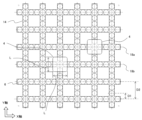
最初に、試料搬送システムの全体構成について図1を用いて説明する。図1は、本発明の試料搬送システムを構成する、試料搬送平面1、および試料搬送キャリア4の外観を示した図である。
図1に示すように、試料搬送システムは試料が収納された容器3を搭載する試料搬送キャリア4を搬送するためのシステムであり、複数の搬送パネル2を水平に配置し、各々を連結することで構成される試料搬送平面1等を備えている。搬送パネル2が任意に連結されることで任意の試料搬送平面1を構築することが可能であり、試料搬送キャリア4の移動範囲を柔軟に設定することができる。試料搬送キャリア4は試料搬送平面1上を移動することで目的位置まで搬送される。
次いで、試料搬送キャリア4と、試料搬送キャリア4を搬送する試料搬送平面1を構成する搬送パネル2と、その内部構造について図2を用いて説明する。図2は試料搬送キャリアおよび搬送パネルの断面図であり、図2中「断面B」におけるA-A断面の様子を示す図が「断面A」であり、「断面A」におけるB-B断面の様子を示す図が「断面B」である。
試料搬送平面1を構成する各々の搬送パネル2は、図2に示すように、試料搬送キャリア4が移動する上面板5の直下に、試料搬送キャリア4の移動経路を形成する複数の永久磁石6が配置されており、これら複数の永久磁石6を永久磁石支持部材7により固定している。永久磁石6はN極、S極が交互に反転して配置されており、ヨーク14と結合して磁気回路を形成する。
試料搬送キャリア4は、ヨーク8、採血管架設部9、カバー10、電磁コイル12、鉄心13、センサー部15、制御部16、蓄電池17等を備えている。
採血管架設部9は、上部に試料を収納した容器3を架設するためのスペースであり、その外周をプラスチック等のカバー10で覆われた構造をしている。
試料搬送キャリア4の内部には、複数の電磁コイル12が内蔵されている。各々の電磁コイル12の鉄心13はヨーク8と結合し、磁気回路を形成する。この電磁コイル12は、試料搬送キャリア4の搬送方向に最小でも3つ以上並んで配置されている。図2に示す形態では、5つ設けられており、図3や図4、図5に示すように異なる2方向以上の移動に対応するように配置されている。
センサー部15は、試料搬送キャリア4の底面付近のうち、電磁コイル12に挟まれる位置に設けられており、搬送パネル2内の永久磁石6の磁力を検知することで永久磁石6との相対位置を把握することができる。センサー部15には、例えば、リニアホールセンサが利用できる。
制御部16は、例えばマイクロコンピュータにより構成され、電磁コイル12の励磁制御を適切に行うことで永久磁石6に磁力を作用させ、試料搬送キャリア4を試料搬送平面1の上面を移動させる。この制御部16は、センサー部15により把握された永久磁石6との相対位置に基づき、電磁コイル12の励磁状態を制御する。
蓄電池17は、電磁コイル12、制御部16、センサー部15などへ電力を供給する内部に蓄電可能な部品であり、例えば、リチウムイオン電池などで構成される。
試料搬送キャリア4の底面は、車輪等の転がり機構を備えることができるが、備えなくても良い。転がり機構を備えない場合は、試料搬送キャリア4が試料搬送平面上を滑走して移動する、非常にシンプルな外形状となる。また、転がり機構を持たないため、これに起因する不具合の発生が無く、信頼性の高い、試料搬送キャリア4を構築できる。これに対し、転がり機構を備える場合は、試料搬送キャリア4の底面と搬送パネル2の上面板5との摩擦を非常に小さくでき、搬送に要する力(電磁コイル12の励磁電流値)を小さくすることができる。
図3および図4は、車輪等の転がり機構を持たない試料搬送キャリア4の場合における、試料搬送平面1との接触面となる試料搬送キャリア4の接触底面の形状の例を図示したものである。
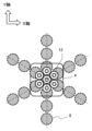
試料搬送平面1と試料搬送平面1との接触底面の形状11a,11bは、試料搬送キャリア4の水平断面の形状と同じとする必要は無く、図3や図4に示すように異なる形状とすることができる。例えば図3に示すように円形としたり、図4に示すように菱形に類した形状にすることができる。なお、図3に示すような円形や図4に示す菱形に類した形状に限られず、他の形状とすることができる。
次いで、図5乃至図9を用いて、電磁コイル12や永久磁石6の配置パターンの具体例について説明する。
図5は、試料搬送キャリア4のX軸方向への移動時において、試料搬送キャリア4内の電磁コイル12と、搬送パネル2内の永久磁石6との位置関係を示す図である。図6および図9は電磁コイル12と永久磁石6との関係を示す図である。図7は、搬送パネル2の永久磁石6の配置例、およびヨーク14の形状を示した図である。図8は、電磁コイル12a,12b,12cの励磁状態、永久磁石6の磁力の強弱を検知するセンサー部15a,15bの出力値、の関係を示した図である。
図5および図6に示すように、試料搬送キャリア4のX軸、およびY軸の2方向の移動に対応した組み合わせを持つように配置されており、電磁コイル12は直交する2方向に3つ以上並んで配置される。
このため、図6および図7に示すように、試料搬送平面1の直下に配置される永久磁石6は、試料搬送キャリア4のX軸、およびY軸方向の移動経路に沿って一定の間隔D1で正方格子状に配置されている。各々の正方格子を構成するX軸、Y軸は、試料搬送キャリア4の移動経路18a,18bを形成する。なお、図7に示す形態では、円形の永久磁石6を使用している場合を例示しているが、四角形など、状況に応じて最適な形状に変更できる。
また、永久磁石6は、X軸、Y軸の各々の交点の間隔D2を間隔D1に対して任意の整数N倍とすることが望ましい。
試料搬送キャリア4は、内部に電磁コイル12等の多数の部品を組み込む必要があるため、内部容積を大きくする断面形状が好ましい。
試料搬送キャリア4の移動経路を図6や図7に示すように正方格子状に形成した場合、移動中あるいは停止中に関わらず、X軸、Y軸方向に対して、常に同じ方向を保っていることを考慮すると、移動中の試料搬送キャリア4同士が干渉する機会を低減し、かつ、試料搬送キャリア4の内部容積の大きくする断面形状は、正方形状を有していることが有利である。正方形の断面を持った試料搬送キャリア4は、それぞれの辺が、移動経路となる正方格子のX軸、Y軸と平行を保ったまま移動する。
ここで、試料搬送キャリア4の底面部の正方形の断面の一辺の長さをLとした場合、交点の間隔D2を一辺の長さLの半分よりも大きくすることが望ましい。
更に、試料搬送キャリア4のX軸方向の電磁コイル12の配置間隔は、永久磁石6の配置間隔D1に対し2/3×D1とすることができる。同様に、試料搬送キャリア4のY軸方向の電磁コイル12の配置間隔についても、永久磁石6の配置間隔D1に対し2/3×D1となっている。
制御部16における複数の電磁コイル12の励磁制御は、X軸、またはY軸方向のどちらか一方の電磁コイル12の組み合わせについて励磁状態を制御することでX軸、またはY軸方向に移動させるものとし、移動原理には、例えば、リニア直流モータの原理が利用できる。
この際、上述のようにセンサー部15の検出値を利用することができる。センサー部15a,15bの出力値は、試料搬送キャリア4の位置の変化に応じて、固有の出力値の組み合わせを持つ。そのため、各々のセンサー部15a,15bの出力値を確認することで、永久磁石と試料搬送キャリア4の相対位置を把握することができる。
試料搬送キャリア4の制御部16は、センサー部15a,15bの出力値を確認し、永久磁石6と試料搬送キャリア4との相対位置を把握すると伴に、電磁コイル12a,12b,12cの励磁状態を図8に示すように切り替え、試料搬送キャリア4をX軸方向に移動させる。
Y軸方向への移動についても、X軸方向への移動の場合と同様の原理に基づき移動させる。図6に示すように、試料搬送キャリア4内の電磁コイル12、および搬送パネル2内の永久磁石は、X軸、Y軸方向に、十字形に配置されていることから、Y軸方向への移動では、図8に示す電磁コイル12d,12b,12eおよび、センサー部15c,15dを使用する。
このように、試料搬送キャリア4の移動方向に応じて、搬送パネル2内の永久磁石を配置する伴に、試料搬送キャリア4内の電磁コイル12が、それぞれの移動方向に対応した配置を持てば、試料搬送キャリア4を任意の方向に移動することができる。
なお、電磁コイル12の配置パターン(=永久磁石6の配置パターン)は図6に示す形態に限られず、試料搬送平面1の形状に応じて適宜変更可能である。例えば、図9に示すように、60度ずれた3方向に移動可能なように、搬送パネル2内の永久磁石6、および試料搬送キャリア4内の電磁コイル12を配置させることができる。この場合、図6に示すような正方格子状に配置される場合に比べて搬送経路の自由度を高くすることができる。
試料搬送キャリア4を目的の位置により適切に移動させるには、センサー部15a,15bの出力値を確認し、永久磁石6と試料搬送キャリア4との相対位置を把握することに加えて、試料搬送平面1内や搬送パネル2内での試料搬送キャリア4の絶対的な位置を把握することが望まれる。
以下そのための構成について図10乃至図13を用いて説明する。
図10は、試料搬送キャリア4の移動経路18a,18bに沿って配置したRFIDタグ19、およびワイヤレス給電部を構成するワイヤレス給電コイル20の配置を示した図である。また、図11および図12は、試料搬送キャリア4がRFIDタグ19と通信を行う際、試料搬送キャリア4の内部に設置した、RFIDタグ19とのRFID読み取りアンテナ21の構成部品と、RFIDタグ19の位置関係を示した図である。図13は、試料搬送キャリア4と外部の制御部28との通信、および試料搬送キャリア4間の通信状態を示した概念図である。
図10に示すように、試料搬送平面1には、試料搬送キャリア4の移動経路に沿って、試料搬送キャリア4の移動を妨げない試料搬送平面1の直下、または表面に非接触通信部としてRFIDタグ19を複数設ける。
更に、図11および図12に示すように、試料搬送キャリア4には、これらRFIDタグ19と通信するRFID読み取りアンテナ21を設ける。
図10等では、非接触通信部にRFIDタグ19を使用し、RFIDタグ19との通信インターフェースの構成部品は、RFID読み取りアンテナ21を示している。RFIDタグ19には、この他、IR通信、バーコードなど、様々な情報記録部の利用が考えられ、通信インターフェースは非接触通信部の仕様に適した構成を採用する。
図11および図12に示すように、試料搬送キャリア4が、移動経路のX軸、あるいはY軸の交点直上に位置した際に、RFIDタグ19とRFID読み取りアンテナ21とが通信に最適な位置になるよう配置されていることが望ましく、RFIDタグ19と試料搬送キャリア4は、一対一の通信を行うことが望ましい。
上述のRFIDタグ19のうち、個々のRFIDタグ19は、それぞれのRFIDタグ19が配置された搬送パネル2を特定する搬送パネル2のシリアルナンバーと、RFIDタグ19が配置された搬送パネル2上の位置を示すRFIDタグ19の位置情報(固有情報)を有していることが望ましい。
また、試料搬送キャリア4の制御部16は、予め、搬送パネル2のシリアルナンバーと個々のRFIDタグ19の位置関係を記憶していることが望ましい。その上で、試料搬送キャリア4がRFIDタグ19の上部に位置した際に、RFIDタグ19から受信した固有情報から搬送パネル2とその中におけるRFIDタグ19を特定し、固有情報に基づいて試料搬送平面1内や搬送パネル2内における試料搬送キャリア4の絶対位置を特定し、搬送中に目的位置までの経路から外れているか否かを確認しながら電磁コイル12の励磁制御を行うことが望ましい。
更に、この他に、試料搬送キャリア4は、試料搬送システム全体を制御する外部の制御部28と無線通信を行う無線通信部29を備え、相互通信を行うことができる。また、無線通信部29は試料搬送キャリア4間での相互通信も可能である。
例えば、試料搬送キャリア4間で、各々の位置情報、移動方向、および動作状態の情報を交換し、ルールに基づき、試料搬送キャリア4の移動の優先順位を決めれば、外部の制御部28を介すことなく自立して移動することも可能である。
次いで、試料搬送キャリア4の蓄電池17の充電に関する構成について図14および図15を用いて説明する。図14および図15は、試料搬送キャリア4がワイヤレス給電部から電力を受電する際、ワイヤレス給電部を構成するワイヤレス給電コイル20と、試料搬送キャリア4のワイヤレス受電部を構成するワイヤレス受電コイル22の位置関係を示した図である。
図14および図15に示すように、蓄電池17への充電は、ワイヤレス給電、受電システムを利用することが望ましい。
搬送パネル2には、試料搬送キャリア4の蓄電池17を充電する給電部として、ワイヤレス給電コイル20が特定のスポットに1つ充電スポットとして設けられている。このワイヤレス給電コイル20は、搬送パネル2の試料搬送面の直下に配置されている。
また、図15に示すように、試料搬送キャリア4はワイヤレス受電コイル22をその底面部に有している。
試料搬送キャリア4の制御部16は、蓄電池17の残容量が低下したと判断した際や、搬送に余裕があると判断した際などには、ワイヤレス受電コイル22がワイヤレス給電コイル20に重なる位置に試料搬送キャリア4を搬送させ、電力を受電し、試料搬送キャリア4の蓄電池17を充電するよう制御する。
なお、ワイヤレス給電コイル20は、1枚の搬送パネル2に対して1つである必要は無く、必要数に応じて設置数を変更することができる。
また、図14に示すように、ワイヤレス給電コイル20の設置スペースを確保するため、ワイヤレス給電コイル20が設けられる付近の永久磁石6の形状を変えることができ、他の個所の永久磁石6のような円形から永久磁石6a,6bのような直方体形状に変えることができる。
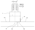
次いで、試料搬送平面1を構成する複数の搬送パネル2の接続に好適な構造の詳細について図16および図17を用いて説明する。図16は、搬送パネル2の連結部の断面を示した図である。図17は、試料搬送キャリア4が端部の傾斜面24を通過する際の、試料搬送キャリア4の重心位置25と、搬送パネル2の端部に設けた傾斜面24の断面形状との関係を示した図である。
試料搬送キャリア4の移動経路は、試料搬送システムの設置仕様に応じて、様々な移動経路を構築する必要がある。そこで、上述のように、移動経路を構築する試料搬送平面1は、分割可能な、複数の搬送パネル2を連結して構成することが望まれる。このような構成であれば、搬送パネル2の連結状態を変更することで様々な設置仕様に応じて柔軟に移動経路を構築することができる。
ここで、搬送パネル2を連結する場合、搬送パネル2間の接続状態によっては、図16に示すように、搬送パネル2と隣の搬送パネル2との間に段差23が発生することが考えられる。
そこで、搬送パネル2の端部に傾斜面24を形成することができる。この傾斜面24は緩やかな傾斜であることが望まれ、試料搬送キャリア4は、段差23が生じていてもスムーズに乗り越えることができる。
ここで、傾斜面24の傾斜角度については、試料搬送キャリア4が端部の傾斜面24を更に安定して通過させるためには、図17に示すように、試料搬送キャリア4の重心位置が平坦部27aから傾斜面24aに到達する前に、試料搬送キャリア4の進行方向の端面26が次の搬送パネル2の傾斜面24bを通過し、平坦部27bに到達することが求められる。
そこで、試料搬送平面1と傾斜面24とがなす角度をθ、隣接する搬送パネル2の間の段差の最大高さをH、試料搬送キャリア4の搬送方向長さをlとしたときに、tanθ≧4H/lの関係式を満たす角度θを選択することができる。この条件を満たす傾斜面24であることで、最も傾斜角を緩やかにできる。
次に、本実施例の効果について説明する。
上述した本実施例の試料搬送システムは、試料が収納された容器3を搭載する試料搬送キャリア4と、試料搬送キャリア4が移動可能な試料搬送平面1と、試料搬送キャリア4の移動経路に沿って試料搬送平面1の下面に複数配置された永久磁石6と、を備え、試料搬送キャリア4は、試料搬送キャリア4の搬送方向に3つ以上並んで配置された、3つ以上の電磁コイル12と、電磁コイル12および制御部16に電力を供給する蓄電池17と、電磁コイル12の励磁状態を制御する制御部16と、を有し、電磁コイル12の励磁状態を制御して永久磁石6に磁力を作用させることで試料搬送キャリア4が試料搬送平面1の上面を移動する。
これによって、試料搬送キャリア4側に電磁コイルを設けることになるため、試料搬送平面の全範囲に電磁コイルを配置する必要がなくなる。従って、質量増加、製造コストアップ、電磁コイルの励磁制御の複雑化等、の懸念が生じない、柔軟、かつ安価で、シンプルな試料搬送システムや、それを実現する試料搬送キャリア、試料容器の搬送方法を得ることができる。
また、試料搬送キャリア4は、電磁コイル12を5つ以上有しており、異なる2方向以上の搬送方向の移動に対応している、特に永久磁石6は正方格子状に配置され、電磁コイル12は、直交する2方向に3つ以上並んで配置されていることで、より柔軟な搬送経路を組むことができるようになる。
更に、永久磁石6の中心と隣あう永久磁石6との中心の距離をD1としたときに、永久磁石6が構成する正方格子のX軸、Y軸の交点の間隔D2がD1の整数倍の距離であることにより、整数Nを変更することで試料搬送平面1に配置する試料搬送キャリア4の移動経路の数を必要数に応じて自由に設定できるようになることから、更に柔軟な搬送経路を実現することができる。
また、試料搬送キャリア4の底面は、その水平断面が正方形状を有していることで、従来技術に比べて多くの構成が設けられる試料搬送キャリア4の内部容積を最大化することができ、無駄な空間が生じることを避け、可能な限りの試料搬送キャリア4の小型化、軽量化を図ることができる。これにより、搬送効率の向上も図ることができる。
更に、永久磁石6が構成する正方格子のX軸、Y軸の交点の間隔D2は、底面の1辺の長さをLとしたときに、Lの半分よりも大きいことにより、2つの試料搬送キャリア4が、隣接する異なる移動経路18a,18bをそれぞれ平行移動する場合であっても、試料搬送キャリア4が互いに干渉すること無く移動させることができ、搬送効率の向上を図ることができる。
また、試料搬送キャリア4は、永久磁石6との相対位置を把握するセンサー部15を更に有し、制御部16は、センサー部15により把握された永久磁石6との相対位置に基づき、電磁コイル12の励磁状態を制御することで、励磁制御の精度の向上を図り、搬送効率の向上を達成することができる。
更に、試料搬送キャリア4は、試料搬送平面1と接触する接触底面の形状11a,11bの断面形状が、試料搬送キャリア4の水平断面の形状と異なることにより、試料搬送キャリア4が移動する際の摩擦力を低減すると伴に、直進安定性を向上させることができる。
また、試料搬送平面1は、試料搬送キャリア4の移動経路に沿ってRFIDタグ19を複数有しており、試料搬送キャリア4は、RFIDタグ19と通信するRFID読み取りアンテナ21を更に有する、特に個々のRFIDタグ19が固有情報を有しており、試料搬送キャリア4の制御部16は、固有情報に基づいて試料搬送平面1内における試料搬送キャリア4の位置を特定することで、試料搬送キャリア4の絶対位置の特定がより容易になり、搬送精度の更なる向上を図ることができる。
更に、非接触通信部は、RFIDタグ19、IR通信、またはバーコードのうち少なくともいずれか一つ以上の情報記録部からなり、通信インターフェースは、情報記録部の情報を読み取るRFID読み取りアンテナ21であることで、速やかで、かつ安定した情報のやり取りを実現することができる。
また、試料搬送キャリア4は無線通信部29を更に有し、他の試料搬送キャリア4との間、または外部の制御部28との相互通信を行うことにより、更に高い精度での搬送制御を実現することができる。
更に、試料搬送平面1は、複数の搬送パネル2により構成され、搬送パネル2が連結されることで任意の試料搬送平面1が構築されていることで、様々な搬送経路を自在に生成することができ、多様な試料搬送システムの設置仕様に応じることができるようになる。
また、搬送パネル2の端部に傾斜面24が形成されていることにより、搬送パネル2の接続部分で段差23が生じたとしても、段差23部分の搬送を安定して行うことができる。
更に、試料搬送キャリア4は、試料搬送平面1と傾斜面24とがなす角度をθ、隣接する搬送パネル2の間の段差の最大高さをH、試料搬送キャリア4の搬送方向長さをlとしたときに、tanθ≧4H/lの関係式を満たすことで、試料搬送キャリア4が端部の傾斜面24を通過する際に、更に安定した移動が可能となる。
また、試料搬送平面1は、蓄電池17を充電する給電部を有する、特に試料搬送キャリア4はワイヤレス受電コイル22を有し、給電部はワイヤレス給電コイル20であることにより、試料搬送キャリア4の充電を容易に行うことができる。
<その他>
なお、本発明は上記の実施例に限られず、種々の変形、応用が可能なものである。上述した実施例は本発明を分かりやすく説明するために詳細に説明したものであり、必ずしも説明した全ての構成を備えるものに限定されない。
なお、本発明は上記の実施例に限られず、種々の変形、応用が可能なものである。上述した実施例は本発明を分かりやすく説明するために詳細に説明したものであり、必ずしも説明した全ての構成を備えるものに限定されない。
1…試料搬送平面
2…搬送パネル
3…容器(試料容器)
4…試料搬送キャリア
5…上面板
6,6a,6b…永久磁石
7…永久磁石支持部材
8,14…ヨーク
9…採血管架設部
10…カバー
11a,11b…形状
12,12a,12b,12c,12d,12e…電磁コイル
13…鉄心
15,15a,15b,15c,15d…センサー部
16…制御部
17…蓄電池(電力供給部)
18a,18b…移動経路
19…RFIDタグ(非接触通信部)
20…ワイヤレス給電コイル(ワイヤレス給電部)
21…RFID読み取りアンテナ(通信インターフェース、記録媒体リーダ)
22…ワイヤレス受電コイル(ワイヤレス受電部)
23…段差
24,24a,24b…傾斜面
25…重心位置
26…端面
27a,27b…平坦部
28…制御部
29…無線通信部
D1,D2…配置間隔
2…搬送パネル
3…容器(試料容器)
4…試料搬送キャリア
5…上面板
6,6a,6b…永久磁石
7…永久磁石支持部材
8,14…ヨーク
9…採血管架設部
10…カバー
11a,11b…形状
12,12a,12b,12c,12d,12e…電磁コイル
13…鉄心
15,15a,15b,15c,15d…センサー部
16…制御部
17…蓄電池(電力供給部)
18a,18b…移動経路
19…RFIDタグ(非接触通信部)
20…ワイヤレス給電コイル(ワイヤレス給電部)
21…RFID読み取りアンテナ(通信インターフェース、記録媒体リーダ)
22…ワイヤレス受電コイル(ワイヤレス受電部)
23…段差
24,24a,24b…傾斜面
25…重心位置
26…端面
27a,27b…平坦部
28…制御部
29…無線通信部
D1,D2…配置間隔
Claims (19)
- 試料が収納された試料容器を搭載する試料搬送キャリアと、
前記試料搬送キャリアが移動可能な試料搬送平面と、
前記試料搬送キャリアの移動経路に沿って前記試料搬送平面の下面に複数配置された永久磁石と、を備え、
前記試料搬送キャリアは、
前記試料搬送キャリアの搬送方向に3つ以上並んで配置された、3つ以上の電磁コイルと、
前記電磁コイルおよび制御部に電力を供給する電力供給部と、
前記電磁コイルの励磁状態を制御する制御部と、を有し、
前記電磁コイルの励磁状態を制御して前記永久磁石に磁力を作用させることで前記試料搬送キャリアが前記試料搬送平面の上面を移動する
ことを特徴とした試料搬送システム。 - 請求項1に記載の試料搬送システムにおいて、
前記試料搬送キャリアは、前記電磁コイルを5つ以上有しており、異なる2方向以上の搬送方向の移動に対応している
ことを特徴とする試料搬送システム。 - 請求項2に記載の試料搬送システムにおいて、
前記永久磁石は正方格子状に配置され、
前記電磁コイルは、直交する2方向に3つ以上並んで配置されている
ことを特徴とする試料搬送システム。 - 請求項3に記載の試料搬送システムにおいて、
前記永久磁石の中心と隣あう前記永久磁石との中心の距離をD1としたときに、前記永久磁石が構成する正方格子のX軸、Y軸の交点の間隔D2が前記D1の整数倍の距離である
ことを特徴とする試料搬送システム。 - 請求項3に記載の試料搬送システムにおいて、
前記試料搬送キャリアの底面は、その水平断面が正方形状を有している
ことを特徴とする試料搬送システム。 - 請求項5に記載の試料搬送システムにおいて、
前記永久磁石が構成する正方格子のX軸、Y軸の交点の間隔D2は、前記底面の1辺の長さをLとしたときに、前記Lの半分よりも大きい
ことを特徴とする試料搬送システム。 - 請求項1に記載の試料搬送システムにおいて、
前記試料搬送キャリアは、前記永久磁石との相対位置を把握するセンサー部を更に有し、
前記制御部は、前記センサー部により把握された前記永久磁石との相対位置に基づき、前記電磁コイルの励磁状態を制御する
ことを特徴とする試料搬送システム。 - 請求項1に記載の試料搬送システムにおいて、
前記試料搬送キャリアは、前記試料搬送平面と接触する接触底面の断面形状が、前記試料搬送キャリアの水平断面の形状と異なる
ことを特徴とする試料搬送システム。 - 請求項1に記載の試料搬送システムにおいて、
前記試料搬送平面は、前記試料搬送キャリアの移動経路に沿って非接触通信部を複数有しており、
前記試料搬送キャリアは、前記非接触通信部と通信する通信インターフェースを更に有する
ことを特徴とする試料搬送システム。 - 請求項9に記載の試料搬送システムにおいて、
前記非接触通信部は、個々の前記非接触通信部が固有情報を有しており、
前記試料搬送キャリアの前記制御部は、前記固有情報に基づいて前記試料搬送平面内における前記試料搬送キャリアの位置を特定する
ことを特徴とする試料搬送システム。 - 請求項9に記載の試料搬送システムにおいて、
前記非接触通信部は、RFIDタグ、IR通信、またはバーコードのうち少なくともいずれか一つ以上の情報記録部からなり、
前記通信インターフェースは、前記情報記録部の情報を読み取る記録媒体リーダである
ことを特徴とする試料搬送システム。 - 請求項1に記載の試料搬送システムにおいて、
前記試料搬送キャリアは無線通信部を更に有し、他の前記試料搬送キャリアとの間、または外部の制御システムとの相互通信を行う
ことを特徴とする試料搬送システム。 - 請求項1に記載の試料搬送システムにおいて、
前記試料搬送平面は、複数の搬送パネルにより構成され、
前記搬送パネルが連結されることで任意の前記試料搬送平面が構築されている
ことを特徴とする試料搬送システム。 - 請求項13に記載の試料搬送システムにおいて、
前記搬送パネルの端部に傾斜面が形成されている
ことを特徴とする試料搬送システム。 - 請求項14に記載の試料搬送システムにおいて、
前記試料搬送キャリアは、前記試料搬送平面と前記傾斜面とがなす角度をθ、隣接する前記搬送パネルの間の段差の最大高さをH、前記試料搬送キャリアの搬送方向長さをlとしたときに、tanθ≧4H/lの関係式を満たす
ことを特徴とする試料搬送システム。 - 請求項1に記載の試料搬送システムにおいて、
前記試料搬送平面は、前記電力供給部を充電する給電部を有する
ことを特徴とする試料搬送システム。 - 請求項16に記載の試料搬送システムにおいて、
前記試料搬送キャリアはワイヤレス受電部を有し、
前記給電部はワイヤレス給電部である
ことを特徴とする試料搬送システム。 - 試料が収納された試料容器を搭載する試料搬送キャリアであって、
前記試料搬送キャリアは、
前記試料搬送キャリアの搬送方向に3つ以上並んで配置された、3つ以上の電磁コイルと、
前記電磁コイルおよび制御部に電力を供給する電力供給部と、
前記電磁コイルの励磁状態を制御する制御部と、を備え、
前記電磁コイルの励磁状態が制御されることで試料搬送キャリアの移動経路に沿って試料搬送平面の下面に複数配置された永久磁石に磁力を作用させることで前記試料搬送平面の上面を移動する
ことを特徴とする試料搬送キャリア。 - 試料容器を搬送する方法であって、
その搬送方向に3つ以上並んで配置された、3つ以上の電磁コイルと、前記電磁コイルと制御部に電力を供給する電力供給部と、前記電磁コイルの励磁状態を制御する制御部と、を備えており、前記試料容器が搭載された試料搬送キャリアを、前記電磁コイルの励磁状態を制御することで前記試料搬送キャリアの移動経路に沿って試料搬送平面の下面に複数配置された永久磁石に磁力を作用させ、前記試料搬送平面の上面を移動させる
ことを特徴とする試料容器の搬送方法。
Applications Claiming Priority (2)
| Application Number | Priority Date | Filing Date | Title |
|---|---|---|---|
| JP2023097752 | 2023-06-14 | ||
| JP2023-097752 | 2023-06-14 |
Publications (1)
| Publication Number | Publication Date |
|---|---|
| WO2024257432A1 true WO2024257432A1 (ja) | 2024-12-19 |
Family
ID=93851851
Family Applications (1)
| Application Number | Title | Priority Date | Filing Date |
|---|---|---|---|
| PCT/JP2024/012382 Ceased WO2024257432A1 (ja) | 2023-06-14 | 2024-03-27 | 試料搬送システム、試料搬送キャリア、および試料容器の搬送方法 |
Country Status (1)
| Country | Link |
|---|---|
| WO (1) | WO2024257432A1 (ja) |
Citations (8)
| Publication number | Priority date | Publication date | Assignee | Title |
|---|---|---|---|---|
| JPH06100164A (ja) * | 1992-08-27 | 1994-04-12 | Hitachi Ltd | 磁気的に結合された搬送装置 |
| WO2013098202A1 (de) * | 2011-12-28 | 2013-07-04 | Siemens Healthcare Diagnostics Products Gmbh | Transportsystem und verfahren zum betrieb |
| JP6290365B2 (ja) * | 2011-11-04 | 2018-03-07 | エフ.ホフマン−ラ ロシュ アーゲーF. Hoffmann−La Roche Aktiengesellschaft | 研究室試料配送システムおよび対応する動作方法 |
| JP2019032344A (ja) * | 2013-02-22 | 2019-02-28 | ベックマン コールター, インコーポレイテッド | 多数のタグを使用したラック方向の検出 |
| JP2019527358A (ja) * | 2016-07-21 | 2019-09-26 | シーメンス・ヘルスケア・ダイアグノスティックス・インコーポレーテッドSiemens Healthcare Diagnostics Inc. | 温度制御式搬送パック |
| WO2020105192A1 (ja) * | 2018-11-22 | 2020-05-28 | 株式会社Fuji | 走行装置 |
| WO2022009476A1 (ja) * | 2020-07-10 | 2022-01-13 | 株式会社日立ハイテク | 検体搬送装置 |
| JP2023077415A (ja) * | 2021-11-24 | 2023-06-05 | エフ ホフマン-ラ ロッシュ アクチェン ゲゼルシャフト | 分配システム |
-
2024
- 2024-03-27 WO PCT/JP2024/012382 patent/WO2024257432A1/ja not_active Ceased
Patent Citations (8)
| Publication number | Priority date | Publication date | Assignee | Title |
|---|---|---|---|---|
| JPH06100164A (ja) * | 1992-08-27 | 1994-04-12 | Hitachi Ltd | 磁気的に結合された搬送装置 |
| JP6290365B2 (ja) * | 2011-11-04 | 2018-03-07 | エフ.ホフマン−ラ ロシュ アーゲーF. Hoffmann−La Roche Aktiengesellschaft | 研究室試料配送システムおよび対応する動作方法 |
| WO2013098202A1 (de) * | 2011-12-28 | 2013-07-04 | Siemens Healthcare Diagnostics Products Gmbh | Transportsystem und verfahren zum betrieb |
| JP2019032344A (ja) * | 2013-02-22 | 2019-02-28 | ベックマン コールター, インコーポレイテッド | 多数のタグを使用したラック方向の検出 |
| JP2019527358A (ja) * | 2016-07-21 | 2019-09-26 | シーメンス・ヘルスケア・ダイアグノスティックス・インコーポレーテッドSiemens Healthcare Diagnostics Inc. | 温度制御式搬送パック |
| WO2020105192A1 (ja) * | 2018-11-22 | 2020-05-28 | 株式会社Fuji | 走行装置 |
| WO2022009476A1 (ja) * | 2020-07-10 | 2022-01-13 | 株式会社日立ハイテク | 検体搬送装置 |
| JP2023077415A (ja) * | 2021-11-24 | 2023-06-05 | エフ ホフマン-ラ ロッシュ アクチェン ゲゼルシャフト | 分配システム |
Similar Documents
| Publication | Publication Date | Title |
|---|---|---|
| JP6619795B2 (ja) | ラボラトリ試料分配システムおよびラボラトリ自動化システム | |
| US10450151B2 (en) | Laboratory sample distribution system and corresponding method of operation | |
| JP6728114B2 (ja) | 研究室試料配送システム | |
| JP5933737B2 (ja) | 研究室試料配送システムおよび対応する動作方法 | |
| EP3191224B1 (en) | Set of sample container carriers for a laboratory sample distribution system, laboratory sample distribution system and laboratory automation system | |
| US10160609B2 (en) | Laboratory sample distribution system and laboratory automation system | |
| EP3410123B1 (en) | Method of operating a laboratory sample distribution system, laboratory sample distribution system and laboratory automation system | |
| WO2016012517A1 (en) | Sample container carrier, laboratory sample distribution system and laboratory automation system | |
| JP6752350B2 (ja) | ラボラトリ試料分配システム及びラボラトリ自動化システム | |
| WO2023081838A1 (en) | Electromagnetic pcb crossroads topologies for automation track systems | |
| EP3567372A1 (en) | Handling system for a tube carrier | |
| WO2023081834A1 (en) | Electromagnetic pcb topologies for automation track systems | |
| US20230160916A1 (en) | Distribution system | |
| US12098039B2 (en) | Body-to-be-conveyed, container carrier, and conveying device | |
| EP3112875A1 (en) | Transport device, laboratory sample distribution system and laboratory automation system | |
| US12306202B2 (en) | Conveyance device | |
| JP7649844B2 (ja) | 検体搬送システム、および検体の搬送方法 | |
| CN120064421A (zh) | 一种集成电磁微流控的葡萄糖电化学检测系统 |
Legal Events
| Date | Code | Title | Description |
|---|---|---|---|
| 121 | Ep: the epo has been informed by wipo that ep was designated in this application |
Ref document number: 24823055 Country of ref document: EP Kind code of ref document: A1 |
|
| NENP | Non-entry into the national phase |
Ref country code: DE |
|
| 122 | Ep: pct application non-entry in european phase |
Ref document number: 24823055 Country of ref document: EP Kind code of ref document: A1 |