WO2024257317A1 - 端末、無線通信方法及び基地局 - Google Patents
端末、無線通信方法及び基地局 Download PDFInfo
- Publication number
- WO2024257317A1 WO2024257317A1 PCT/JP2023/022322 JP2023022322W WO2024257317A1 WO 2024257317 A1 WO2024257317 A1 WO 2024257317A1 JP 2023022322 W JP2023022322 W JP 2023022322W WO 2024257317 A1 WO2024257317 A1 WO 2024257317A1
- Authority
- WO
- WIPO (PCT)
- Prior art keywords
- cell
- measurement
- timing advance
- information
- candidate
- Prior art date
- Legal status (The legal status is an assumption and is not a legal conclusion. Google has not performed a legal analysis and makes no representation as to the accuracy of the status listed.)
- Ceased
Links
Images











Classifications
-
- H—ELECTRICITY
- H04—ELECTRIC COMMUNICATION TECHNIQUE
- H04W—WIRELESS COMMUNICATION NETWORKS
- H04W56/00—Synchronisation arrangements
- H04W56/004—Synchronisation arrangements compensating for timing error of reception due to propagation delay
- H04W56/0045—Synchronisation arrangements compensating for timing error of reception due to propagation delay compensating for timing error by altering transmission time
Definitions
- This disclosure relates to terminals, wireless communication methods, and base stations in next-generation mobile communication systems.
- LTE Long Term Evolution
- UMTS Universal Mobile Telecommunications System
- Non-Patent Document 1 LTE-Advanced (3GPP Rel. 10-14) was specified for the purpose of achieving higher capacity and greater sophistication over LTE (Third Generation Partnership Project (3GPP) Release (Rel.) 8 and 9).
- 3GPP Third Generation Partnership Project
- LTE 5th generation mobile communication system
- 5G+ 5th generation mobile communication system
- 6G 6th generation mobile communication system
- NR New Radio
- inter-cell mobility including non-serving cells, or inter-cell mobility using multiple transmission/reception points (e.g., Multi-TRP (MTRP)).
- MTRP Multi-TRP
- candidate cells will be set in addition to the serving cell, and switching between the serving cell and the candidate cell will be performed.
- the issue is how to control UL transmission (for example, control of timing advance, etc.). For example, it is expected that UE-based TA measurement will be supported as a method of acquiring timing advance.
- This disclosure has been made in consideration of these points, and one of its objectives is to provide a terminal, a wireless communication method, and a base station that are capable of appropriately controlling communications even when UE-based timing advance measurement is supported.
- a terminal has a receiving unit that receives a signal that triggers a UE-based timing advance measurement, and a control unit that performs a UE-based timing advance measurement for a candidate cell based on the signal, and the control unit controls the execution of the UE-based timing advance measurement based on whether or not the signal includes an indication of the candidate cell for which the UE-based timing advance measurement is to be performed, or based on the reception of a physical downlink control channel order.
- communications can be appropriately controlled even when UE-based timing advance measurements are supported.
- FIG. 1A is a diagram showing an example of UE movement in Rel. 17.
- Figure 1B is a diagram showing an example of UE movement in Rel. 18.
- FIG. 2 is a diagram showing an example of association between a serving cell and a candidate cell.
- 3A and 3B are diagrams illustrating a second and a third example of the candidate cell configuration option 2.
- FIG. 4 is a diagram showing a serving cell switch example 1.
- FIG. 5 is a diagram showing a serving cell switch example 2.
- FIG. 6 is a diagram showing a serving cell switch example 3.
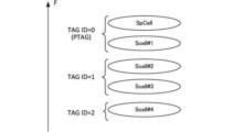
- FIG. 7 is a diagram showing an example of a timing advance group (TAG) to which cells included in a cell group belong.
- Figure 8 shows an example of a MAC CE for a timing advance command.
- TAG timing advance group
- FIG. 9 shows another example of a MAC CE for a timing advance command.
- Figure 10 shows an example of TAG configuration when TAG ID association with a candidate cell is supported.
- Figure 11 shows an example of a MAC CE for timing advance reporting.
- Figure 12 shows an overview of L1L2-triggered mobility (LTM).
- FIG. 13 illustrates a PDCCH ordered RACH with random access response (RAR) monitoring for a serving cell.
- FIG. 14 illustrates a PDCCH ordered RACH without random access response (RAR) monitoring for a candidate cell.
- FIG. 15 is a diagram showing an example of UE-based TA measurement.
- FIG. 16 is a diagram showing an example of UE-based TA measurement according to the 0th embodiment.
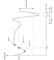
- FIG. 17 is a diagram illustrating an example of a criterion for determining the validity of a TA according to the first embodiment.
- FIG. 18 is a diagram illustrating an example of a criterion for determining the validity of a TA according to the first embodiment.
- FIG. 19 is a diagram illustrating an example of a schematic configuration of a wireless communication system according to an embodiment.
- FIG. 20 is a diagram illustrating an example of the configuration of a base station according to an embodiment.
- FIG. 21 is a diagram illustrating an example of the configuration of a user terminal according to an embodiment.
- FIG. 22 is a diagram illustrating an example of the hardware configuration of a base station and a user terminal according to an embodiment.
- FIG. 23 is a diagram illustrating an example of a vehicle according to an embodiment.
- TCI transmission configuration indication state
- the TCI state may represent that which applies to the downlink signal/channel.
- the equivalent of the TCI state which applies to the uplink signal/channel may be expressed as a spatial relation.
- TCI state is information about the Quasi-Co-Location (QCL) of signals/channels and may also be called spatial reception parameters, spatial relation information, etc. TCI state may be set in the UE on a per channel or per signal basis.
- QCL Quasi-Co-Location
- QCL is an index that indicates the statistical properties of a signal/channel. For example, if a signal/channel has a QCL relationship with another signal/channel, it may mean that it can be assumed that at least one of the Doppler shift, Doppler spread, average delay, delay spread, and spatial parameters (e.g., spatial Rx parameters) is identical between these different signals/channels (i.e., it is QCL with respect to at least one of these).
- spatial parameters e.g., spatial Rx parameters
- the spatial reception parameters may correspond to a reception beam (e.g., a reception analog beam) of the UE, and the beam may be identified based on a spatial QCL.
- the QCL (or at least one element of the QCL) in this disclosure may be interpreted as sQCL (spatial QCL).
- QCL types QCL types
- QCL types A to D QCL types A to D
- the parameters (which may be called QCL parameters) are as follows: QCL Type A (QCL-A): Doppler shift, Doppler spread, mean delay and delay spread, QCL type B (QCL-B): Doppler shift and Doppler spread, QCL type C (QCL-C): Doppler shift and mean delay; QCL Type D (QCL-D): Spatial reception parameters.
- QCL Type A QCL-A
- QCL-B Doppler shift and Doppler spread
- QCL type C QCL type C
- QCL Type D QCL Type D
- the UE's assumption that a Control Resource Set (CORESET), channel or reference signal is in a particular QCL (e.g., QCL type D) relationship with another CORESET, channel or reference signal may be referred to as a QCL assumption.
- CORESET Control Resource Set
- QCL QCL type D
- the UE may determine at least one of a transmit beam (Tx beam) and a receive beam (Rx beam) for a signal/channel based on the TCI condition or QCL assumption of the signal/channel.
- Tx beam transmit beam
- Rx beam receive beam
- the TCI state may be, for example, information regarding the QCL between the target channel (in other words, the Reference Signal (RS) for that channel) and another signal (e.g., another RS).
- the TCI state may be set (indicated) by higher layer signaling, physical layer signaling, or a combination of these.
- target channel/RS target channel/reference signal
- reference RS reference signal
- the channel for which the TCI state or spatial relationship is set (specified) may be, for example, at least one of the following: a downlink shared channel (Physical Downlink Shared Channel (PDSCH)), a downlink control channel (Physical Downlink Control Channel (PDCCH)), an uplink shared channel (Physical Uplink Shared Channel (PUSCH)), and an uplink control channel (Physical Uplink Control Channel (PUCCH)).
- PDSCH Physical Downlink Shared Channel
- PDCCH Physical Downlink Control Channel
- PUSCH Physical Uplink Shared Channel
- PUCCH Physical Uplink Control Channel
- the RS that has a QCL relationship with the channel may be, for example, at least one of a synchronization signal block (SSB), a channel state information reference signal (CSI-RS), a sounding reference signal (SRS), a tracking CSI-RS (also called a tracking reference signal (TRS)), a QCL detection reference signal (also called a QRS), a demodulation reference signal (DMRS), etc.
- SSB synchronization signal block
- CSI-RS channel state information reference signal
- SRS sounding reference signal
- TRS tracking reference signal
- QRS QCL detection reference signal
- DMRS demodulation reference signal
- An SSB is a signal block that includes at least one of a Primary Synchronization Signal (PSS), a Secondary Synchronization Signal (SSS), and a Physical Broadcast Channel (PBCH).
- PSS Primary Synchronization Signal
- SSS Secondary Synchronization Signal
- PBCH Physical Broadcast Channel
- An SSB may also be referred to as an SS/PBCH block.
- An RS of QCL type X in a TCI state may refer to an RS that has a QCL type X relationship with a certain channel/signal (DMRS), and this RS may be called a QCL source of QCL type X in that TCI state.
- DMRS channel/signal
- the serving cell may be read as a TRP in the serving cell.
- Layer 1/layer 2 (L1/L2) and DCI/Medium Access Control Control Element (MAC CE) may be read as each other.
- MAC CE DCI/Medium Access Control Control Element
- a PCI different from the physical cell identity (PCI) of the current serving cell may be simply described as a "different PCI".
- a non-serving cell, a cell having a different PCI, and an additional cell may be read as each other.
- Scenario 1 corresponds to, for example, multi-TRP inter-cell mobility, but it may also be a scenario that does not correspond to multi-TRP inter-cell mobility.
- the UE receives from the serving cell an SSB configuration for beam measurement of a TRP corresponding to a PCI different from that of the serving cell, and a configuration required to use radio resources for data transmission and reception (including resources of a different PCI).
- the UE performs beam measurements of TRPs corresponding to different PCIs and reports the beam measurement results to the serving cell.
- the Transmission Configuration Indication (TCI) states associated with the TRPs corresponding to different PCIs are activated by L1/L2 signaling from the serving cell.
- the UE transmits and receives using UE-dedicated channels on TRPs corresponding to different PCIs.
- the UE must always cover the serving cell, including in the case of multi-TRP.
- the UE must use common channels (Broadcast Control Channel (BCCH), Paging Channel (PCH)) from the serving cell, as in the conventional system.
- BCCH Broadcast Control Channel
- PCH Paging Channel
- scenario 1 when the UE transmits and receives signals to and from an additional cell/TRP (a TRP corresponding to the PCI of the additional cell), the serving cell (the serving cell assumption in the UE) is not changed.
- the UE is configured with higher layer parameters related to the PCI of the non-serving cell from the serving cell. Scenario 1 may be applied, for example, in Rel. 17.
- Figure 1A shows an example of UE movement in Rel. 17. Assume that the UE moves from a cell (serving cell) with PCI #1 to a cell (additional cell) with PCI #3 (which overlaps with the serving cell). In this case, Rel. 17 does not support switching of the serving cell via L1/L2.
- An additional cell is a cell that has an additional PCI that is different from the PCI of the serving cell.
- the UE can receive/transmit UE-dedicated channels (UE-dedicated CH) from the additional cell.
- UE-dedicated CH UE-dedicated channels
- the UE needs to be within the coverage of the serving cell to receive UE common channels (e.g., system information/paging/short messages).
- a cell switch e.g., RRC reconfiguration or other processing
- handover also called L3 mobility
- L1/L2 inter-cell mobility e.g., L1L2-triggered mobility (LTM)
- L1/L2 inter-cell mobility the serving cell can be changed using a function such as beam control without RRC reconfiguration.
- L1/L2 inter-cell mobility the serving cell can be changed using a function such as beam control without RRC reconfiguration.
- transmission and reception with a candidate cell/additional cell is possible without handover. Since handover requires RRC reconnection and creates a period during which data communication is not possible, by applying L1/L2 inter-cell mobility that does not require handover, data communication can be continued even when the serving cell is changed.
- Scenario 2 may be applied in, for example, Rel. 18. In scenario 2, for example, the following procedure is performed.
- the UE receives configuration information (e.g., SSB configuration, etc.) regarding cells (additional cells/candidate cells/target serving cells) with different PCIs for beam measurement/serving cell change from the serving cell (current serving cell).
- the UE performs beam measurements of cells using different PCIs and reports the measurement results to the serving cell.
- the UE may receive a configuration of a cell having a different PCI (serving cell/candidate cell configuration) by higher layer signaling (e.g., RRC). That is, a pre-configuration regarding a serving cell change may be performed. This configuration may be performed together with the configuration in (1) or separately.
- the TCI states of cells with different PCIs may be activated by L1/L2 signaling according to the change of serving cell.
- the activation of the TCI state and the change of serving cell may be performed separately.
- the UE changes the serving cell (assumed serving cell) and starts receiving/transmitting using the pre-configured UE-specific channel and TCI state.
- scenario 2 the serving cell (the assumed serving cell in the UE) is updated by L1/L2 signaling.
- Scenario 2 may be applied in Rel. 18.
- FIG. 1B is a diagram showing an example of UE movement in Rel. 18.
- the serving cell is switched by L1/L2 (e.g., DCI/MAC CE).
- L1/L2 e.g., DCI/MAC CE
- a case is shown in which the serving cell is switched from PCI #1 corresponding to the current serving cell (e.g., Current serving cell) to PCI #3 corresponding to a candidate cell (e.g., Target serving cell) by L1/L2 signaling.
- the UE can receive/transmit common channels (e.g., system information/paging/short messages)/UE-specific channels between the new serving cell (target serving cell #3). This allows the UE to be out of the coverage of the previous serving cell PCI #1.
- common channels e.g., system information/paging/short messages
- FIG. 2 is a diagram showing an example of the association between a serving cell and a candidate cell.
- SpCell#0, SCell#1, or SCell#2 is assumed to be a serving cell (e.g., a current serving cell/a candidate cell to become a serving cell).
- SpCell means a special cell (including a primary cell (PCell) and a primary secondary cell (PSCell)).
- SCell means a secondary cell.
- a candidate cell (e.g., a target serving cell/candidate cell that is not the current serving cell) may be associated with the SpCell/SCell.
- SpCell#0 is associated with candidate cell#0-1, candidate cell#0-2, and candidate cell#0-3.
- SCell#1 is associated with candidate cell#1-1.
- SCell#2 is associated with candidate cell#2-1 and 2-2.
- one or more candidate cells e.g., a target serving cell/candidate cell that is not the current serving cell
- candidate cells may not be explicitly associated with each serving cell.
- the following options 1 and 2 can be considered for setting candidate cells.
- the information in ServingCellConfig may include information about multiple candidate cells, in which case the multiple candidate cells need to share the same PDCCH/PDSCH/UL etc. configurations as the serving cell.
- mimoParam-r17 is added under ServingCellConfig, and PCI setting information is added.
- mimoParam-r17 may include additionalPCI-ToAddModList-r17, which is an information list of additional SSBs with a PCI different from the PCI of the serving cell. The same settings as the serving cell may be applied to candidate cells (additional cells, cells with additionalPCI), with the exception of some information.
- a complete configuration (e.g., ServingCellConfig) corresponding to each cell may be applied. That is, the candidate cells may not share configuration information with the serving cell and may apply a different configuration (e.g., different upper layer parameters).
- the UE is provided with the complete configuration of each candidate cell, so that it can communicate properly with the candidate cells.
- multiple candidate cells may be associated with each serving cell by reusing the carrier aggregation (CA) configuration framework.
- CA configuration framework an SpCell may be configured for each cell group, and multiple SCells may be added.
- a serving cell may be configured and multiple candidate cells may be configured for each cell group for L1/L2 inter-cell mobility.
- the candidate cells may be activated/deactivated by the MAC CE.
- the candidate cells may be activated/deactivated by activating/deactivating the TCI information corresponding to the candidate cells by the MAC CE. This method is considered to be beneficial for reducing the complexity of UE operations.
- FIG. 3A is a diagram showing a first example of option 2 for candidate cell configuration.
- a common candidate cell pool for cell switching in the MCG/SCG is applied to the candidate cells.
- the candidate cells are treated as one pool (group) regardless of the frequency band.
- Figure 3B is a diagram showing a second example of option 2 for candidate cell configuration.
- multiple cell groups are configured, and cell group switching is possible by L1/L2 signaling.
- Candidate cells are configured for each cell group, and the configuration for each group includes the indices of the corresponding SpCell and SCell.
- At least one of implicit signaling and explicit signaling may be used to indicate a serving cell change.
- a particular Control Resource Set (e.g., at least one of CORESET#0, CORESET of CH5 Type0-CSS, CORESET of CH6/CH7/CH8 CSS) is indicated (activated) by a MAC CE together with one or more TCI states associated with a cell of a PCI different from that of the serving cell (when, for a particular CORESET, one or more TCI states associated with a cell of a PCI different from that of the serving cell are indicated/activated by a MAC CE), the UE may determine to change the serving cell to another cell (cell x, a cell with a different PCI). That is, this activation may implicitly indicate changing the serving cell to another cell.
- CORESET Control Resource Set
- the UE may update beams of other CORESET IDs, other CORESETs using CH6/CH7/CH8, or other CORESETs using CSS to the same TCI state as the activated TCI state.
- the UE may determine to change the serving cell to another cell (cell x), i.e., the association may implicitly indicate the change of the serving cell to another cell.
- the NW base station
- the MAC CE activates the TCI state of a PDSCH associated with a cell with a different PCI, it must also include the TCI state related to another cell (e.g., the current serving cell or a cell with a second different PCI).
- the UE may determine to change the serving cell to another cell (cell x), i.e., the association may implicitly indicate the serving cell change to another cell.
- Option 2-1 An example of a serving cell change instruction will be described below. Note that activation/deactivation of a non-serving cell, change of a serving cell, and transmission/reception with another cell (non-serving cell) having a physical cell ID different from the physical cell ID of the serving cell may be interpreted as being interchangeable.
- the UE may receive a new MAC CE including at least one of the fields (information) indicating the following (1) to (3) corresponding to the non-serving cell, which is used for activating/deactivating the non-serving cell.
- the UE may decide to change the serving cell to another cell (non-serving cell).
- the UE may also control transmission and reception of DL signals/UL signals with the non-serving cell based on the information.
- the non-serving cell may be one or multiple. In the example shown below, a MAC CE including multiple fields indicating multiple non-serving cell indexes is applied.
- Non-serving cell ID used for activation The non-serving cell ID may be replaced with any information corresponding to a non-serving cell (capable of identifying a non-serving cell).
- any of (3-1) to (3-5) may be applied.
- (3-1) PCI PCI used directly). For example, 10 bits are used.
- CSI resource configuration ID (CSI-ResourceConfigId) (when CSI-ResourceConfigId corresponds to one or more non-serving cells).
- CSI-ResourceConfigId (when CSI-ResourceConfigId corresponds to one or more non-serving cells).
- 3-5 A bitmap indicating the activation/deactivation of each non-serving cell.
- the size (number of bits) of the bitmap may be the same as the number of non-serving cells configured on this CC. For example, when activating the second non-serving cell among three non-serving cells, "010" is set.
- At least one of the pieces of information included in the MAC CE may be included in the DCI. Or, at least one of the serving cells activated by the MAC CE may be indicated by the DCI.
- the MAC CE/DCI may include a field indicating the TCI status/SSB/CSI-RS from a cell with a different PCI so that the UE can recognize the DL beam to be monitored on the target cell (the serving cell after the change).
- the UE may create and transmit a beam report (CSI report) using the TCI status/SSB/CSI-RS.
- the UE may receive a MAC CE in which a new 1-bit field "C" is added to the existing MAC CE.
- the field indicates whether to change the serving cell.
- the UE may receive the MAC CE and determine whether to change the serving cell to another cell based on the field.
- a field indicating the serving cell index/PCI/other ID (such as the new ID in Option 2-1 described above) and a field indicating the TCI state/SSB/CSI-RS of the target cell (the serving cell after the change) may be included in the MAC CE.
- the UE can appropriately change the serving cell.
- Fig. 4 is a diagram showing a serving cell switch example 1. Fig. 4 shows a case where candidate cells are associated with each serving cell.
- the serving cell SpCell #0 of the MCG/SCG is instructed by L1/L2 signaling to change the candidate cell #0-2 to a serving cell (e.g., SpCell)
- the candidate cell #0-2 becomes the new serving cell SpCell.
- a switch is made between the serving cell SpCell #0 and the candidate cell #0-2.
- the serving cell SCell#2 of the MCG/SCG is instructed by L1/L2 signaling to change the candidate cell#2-1 to a serving cell (e.g., SCell)
- the candidate cell#2-1 becomes the new serving cell SCell. In other words, switching is performed between the serving cell SCell#2 and the candidate cell#2-1.
- the RRC/MAC CE can configure a global candidate cell ID (cell #0,...,8) for each cell group, band, FR, and UE.
- the UE may be instructed to switch serving cells by the global candidate cell ID.
- Figure 5 shows a serving cell switch example 2. Similar to Figure 3A, a pool of multiple candidate cells can be configured, and the serving cell can be switched to any (activated) candidate cell in the pool by L1/L2 signaling.
- the configured candidate cell can be either an SpCell or an SCell based on L1/L2 signaling.
- candidate cell #4 becomes the new serving cell SpCell. In other words, switching is performed between serving cell SpCell #0 and candidate cell #4.
- the UE may receive an instruction to change the serving cell (here, switching between serving cell SPCell#0 and candidate cell#4) via MAC CE/DCI. The UE may then determine that the instructed candidate cell#4 will become the SpCell of the new cell group.
- Serving Cell Switch Example 3 6 is a diagram showing a serving cell switch example 3. Here, a case where a cell group switch is instructed by L1/L2 signaling is shown.
- the UE receives an instruction to change the serving cell (here, switching between the cell group including SpCell #0/#1/#2 and the cell group including candidate cells #0/#1/#2) via MAC CE/DCI. Then, a specific cell (here, candidate cell #0) included in the cell group to which the switching is to be made becomes the serving cell SpCell.
- a specific cell here, candidate cell #0
- the specific cell becomes a candidate cell corresponding to the same frequency as the SpCell, but this is not limited to this.
- a specific cell may also be indicated.
- the candidate cells (here, candidate cells #1 and #2) included in the same cell group as candidate cell #0 become the SCell.
- the serving cell group and the candidate cell group are switched by L1/L2 signaling.
- the distance between the UE and each TRP may be different.
- the multiple TRPs may be included in the same cell (e.g., a serving cell).
- one TRP among the multiple TRPs may correspond to a serving cell and the other TRPs may correspond to a non-serving cell. In this case, it is also assumed that the distance between each TRP and the UE may be different.
- the transmission timing of UL (Uplink) channels and/or UL signals (UL channels/signals) is adjusted by the Timing Advance (TA).
- TA Timing Advance
- the reception timing of UL channels/signals from different user terminals is adjusted by the radio base station (TRP: Transmission and Reception Point, also known as gNB: gNodeB, etc.).
- the UE may control the timing of UL transmission by applying a timing advance (multiple timing advances) for each pre-configured timing advance group (TAG: Timing Advance Group).
- TAG Timing Advance Group
- Timing Advance Groups classified by transmission timing are supported.
- the UE may control the UL transmission timing for each TAG, assuming that the same TA offset (or TA value) is applied to each TAG.
- the TA offset may be set independently for each TAG.
- the UE can independently adjust the transmission timing of cells belonging to each TAG, allowing the radio base station to align the reception timing of uplink signals from the UE even when multiple cells are used.
- TAGs may be configured by higher layer parameters.
- the same timing advance value may be applied to serving cells (e.g., serving cells for which UL is configured) belonging to the same TAG.
- a timing advance group including the SpCell of a MAC entity may be called a Primary Timing Advance Group (PTAG), and other TAGs may be called Secondary Timing Advance Groups (STAGs).
- PTAG Primary Timing Advance Group
- STAGs Secondary Timing Advance Groups
- FIG. 7 shows a case where three TAGs are configured for a cell group including SpCell and SCell#1 to #4.
- SpCell and SCell#1 belong to the first TAG (PTAG or TAG#0)
- SCell#2 and SCell#3 belong to the second TAG (TAG#1)
- SCell#4 belongs to the third TAG (TAG#2).
- the timing advance command may be notified to the UE using a MAC control element (e.g., MAC CE).
- the TA command is a command indicating the transmission timing value of the uplink channel and is included in the MAC control element.
- the TA command (TAC) is signaled from the radio base station to the UE at the MAC layer.
- the UE controls a predetermined timer (e.g., TA timer) based on the reception of the TA command.
- the MAC CE for the timing advance command may include a field for a timing advance group index (e.g., TAG ID) and a field for the timing advance command (see FIG. 8).
- the TAG ID field may consist of, for example, 2 bits.
- the TAG ID field may be used to indicate the TAG ID of the addressed TAG.
- the Timing Advance Command field may consist of, for example, 6 bits.
- the TAC field may indicate an index value T A (0, 1, 2...63) that is used to control the amount/value (relative amount/value) of timing adjustment that the MAC entity has to apply.
- the MAC CE for the Timing Advance Command shown in Figure 8 may be called TAC MAC CE.
- FIG. 9 is a diagram showing another example of a MAC CE for a timing advance command.
- the MAC CE shown in FIG. 9 may be called an absolute TAC MAC CE.
- the MAC CE may include a field for reserved bits (R bit field) and a field for a timing advance command (TAC field).
- the TAC field may be composed of, for example, 12 bits across two octets.
- the TAC field in FIG. 9 may indicate an index value used to control the amount/value (absolute amount/value) of the actual TA that the MAC entity must apply, as in FIG. 8.
- the absolute TAC MAC CE may not include the TAG ID field shown in FIG. 8.
- the MAC CE shown in FIG. 8 may be used after initial access is established.
- the MAC CE shown in FIG. 9 is used only at the time of initial access and may be included in the RAR, etc.
- Each field included in the MAC CE for the timing advance command described above may be called a field related to TA.
- the TAC field shown in FIG. 8 may be called a TA adjustment field/field for instructing TA adjustment/field related to TA adjustment
- the TAC field shown in FIG. 9 may be called an absolute TAC field/field for instructing absolute TAC.
- UL transmission is controlled based on timing advance for a serving cell (or a TRP of a serving cell) and a non-serving cell/additional cell (or a TRP of a non-serving cell/additional cell).
- TAGs or TAG-IDs
- different TAGs are set for one or more TRPs (e.g., multiple TRPs having different PCIs) corresponding to a certain cell (or CC).
- TRPs corresponding to a certain cell share a common TAG.
- FIG. 10 shows an example of TAG settings for multiple cells (or TRPs) with different PCIs.
- a maximum of M PCIs (e.g., serving cell + candidate cells associated with the serving cell) can be configured for each CC, and it is assumed that the configuration of a maximum of N TAGs (e.g., N ⁇ M) is supported for the maximum M PCIs. In this case, one or more PCIs may be associated with one TAG.
- one or more PCIs may be associated with one TAG for up to S serving cells in a cell group (or for up to S serving cells).
- up to T TAGs may be configured considering one PCI for each CC (Case 1).
- up to T ⁇ N TAGs may be configured for up to M ⁇ S cells.
- up to U TAGs may be configured for up to M ⁇ S cells (Case 2).
- the TAG of the candidate cell may be indicated by the base station or may be determined based on the TA of the candidate cell acquired by the UE.
- the UE performs UL transmission of a candidate cell while taking into account the TA corresponding to the candidate cell.
- the UE needs to acquire the TA of the candidate cell (for example, TA acquisition of candidate cells).
- TA acquisition of a candidate cell several TA acquisition methods are possible, such as TA acquisition using RACH (e.g., RACH-based solutions) and TA acquisition without using RACH (RACH-less solutions).
- RACH e.g., RACH-based solutions
- RACH-less solutions TA acquisition without using RACH
- a TA acquisition method may be interpreted as a TA acquisition scheme, a TA acquisition type, or a TA acquisition procedure.
- TA acquisition, TA measurement, TA calculation, TA calculation, and TA determination may be interpreted as mutually interchangeable.
- the UE may obtain the TA of the candidate cell by transmitting a RACH (e.g., a PDCCH ordered RACH) indicated/triggered by the PDCCH to the candidate cell.
- a RACH e.g., a PDCCH ordered RACH
- Information regarding the TA of the candidate cell e.g., a TA value
- a response signal e.g., an RAR
- the RAR may be transmitted from the serving cell or the candidate cell.
- the TA of the candidate cell may be obtained using a RACH triggered by the UE or a RACH triggered at higher layers by the network.
- the PDCCH order may be triggered only by the source cell (or the serving cell).
- the UE may obtain the TA of the candidate cell by transmitting a signal other than RACH to the candidate cell.
- Information regarding the TA of the candidate cell e.g., the TA value
- SRS may be applied as a signal other than RACH (e.g., SRS-based TA measurement).
- the UE may measure/calculate/obtain the TA for the candidate cell based on DL signals (e.g., downlink reference signals) transmitted from each cell (e.g., candidate cell/serving cell).
- DL signals e.g., downlink reference signals
- a method in which the UE obtains the TA for the candidate cell based on DL signals transmitted from one or more cells may be called UE-based TA measurement (e.g., UE based TA measurement).
- the downlink reference signal may be a specific DL signal (e.g., a synchronization signal block (e.g., SSB)/CSI-RS, etc.).
- the UE may measure the difference/difference in reception timing of DL signals from multiple cells (or two cells) and obtain the TA of a candidate cell.
- the multiple cells may include a reference cell (e.g., a serving cell).
- the UE may calculate the TA required for the candidate cell based on the reception timing of the reference cell (and the TA value of the reference cell) and the timing difference (e.g., T) between the reference cell and the candidate cell.
- the UE may obtain the TA of the candidate cell using a timing advance command (TAC) transmitted from the serving cell.
- TAC timing advance command
- Time alignment timer e.g., timeAlignmentTimer
- TAG Time Alignment Time Alignment timer
- the time alignment timer per TAG may control the time at which the MAC entity considers the serving cells belonging to the associated TAG to be UL time aligned.
- Parameters corresponding to each TAG ID may be set by higher layer parameters. For example, parameters such as a time alignment timer (e.g., timeAlignmentTimer) corresponding to each TAG ID may be set. Alternatively, the TAG ID for each serving cell may be set by higher layer parameters (e.g., tag-ID included in ServingCellConfig). After being set by higher layer parameters, the TAG ID/parameters may be updated by the MAC CE.
- time alignment timer e.g., timeAlignmentTimer
- the TAG ID for each serving cell may be set by higher layer parameters (e.g., tag-ID included in ServingCellConfig).
- a time alignment timer may be maintained for UL time alignment.
- the time alignment timer may be configured/associated per TAG.
- the UE receives a MAC CE for a timing advance command (e.g., TAC MAC CE), it starts/restarts the time alignment timer associated with the indicated timing advance group (e.g., TAG), respectively.
- the MAC entity receives a MAC CE for a timing advance command and applies the timing advance command to the indicated TAG and starts or restarts a time alignment timer associated with the indicated TAG if a predefined value (N TA ) is maintained between the indicated TAG , which may be the timing advance between DL and UL.
- N TA a predefined value
- a timing advance command is received in an RAR message for a serving cell belonging to a TAG (e.g., a TAG of an SpCell) or in a message B (e.g., MSGB) for the SpCell, if the MAC entity does not select a random access preamble from among the collision-based random access preambles, it may apply the timing advance command for that TAG and may also start or restart the time alignment timer associated with that TAG.
- a TAG e.g., a TAG of an SpCell
- a message B e.g., MSGB
- an absolute timing advance command (e.g., Absolute Timing Advance Command) is received in response to transmitting a message A (e.g., MSGA) containing a specific RNTI MAC CE (e.g., C-RNTI MAC CE)
- a message A e.g., MSGA
- a specific RNTI MAC CE e.g., C-RNTI MAC CE
- TAG timing advance group
- STAG secondary timing advance groups
- Rel. 17 supports the application of a specific PTAG operation when a timing advance timer corresponding to a PTAG expires, and the application of a specific STAG operation when a timing advance timer corresponding to a STAG expires.
- the following operations e.g., a specified PTAG operation/a specified STAG operation
- the following operations e.g., a specified PTAG operation/a specified STAG operation
- Predetermined PTAG Operation If a time alignment timer is associated with the PTAG, Flush all HARQ buffers of all serving cells. - If configured, inform RRC to release PUCCH for all serving cells. - If set, notify RRC to release SRS. Clear all configured DL allocations and configured UL allocations. Clear the PUSCH resources for semi-persistent CSI reporting. - Allow all time alignment timers to expire while running. - Maintain NTAs for all TAGs.
- Predetermined STAG Actions If a time alignment timer is associated with a STAG, then for all serving cells belonging to that STAG: Flush all HARQ buffers. - If configured, notify RRC to release PUCCH. - If set, notify RRC to release SRS. Clear all configured DL and UL allocations. Clear the PUSCH resources for semi-persistent CSI reporting. - Maintain the NTA of the TAG.
- Timing advance report A timing advance reporting (e.g., Timing Advance Reporting (TAR)) procedure may be performed to provide the base station with an estimate of the UE's timing advance value.
- the parameters/conditions for the timing advance reporting may be configured by the RRC.
- the timing advance reporting may be triggered when a predefined event occurs.
- the specified event may be, for example, at least one of the following: when an instruction to trigger a timing advance report is received from a higher layer; when a specified parameter (e.g., an offset threshold TA (offsetThresholdTA)) is set by the higher layer; and when the variation between the current estimate of the timing advance value and the last reported timing advance value is equal to or greater than the specified parameter.
- a specified parameter e.g., an offset threshold TA (offsetThresholdTA)
- the UE may perform timing advance reporting using a predefined MAC CE (e.g., a timing advance report MAC CE). Even if multiple events trigger timing advance reporting, a MAC PDU may contain at most one timing advance report MAC CE. When a MAC PDU is transmitted and contains a timing advance report MAC CE, all triggered timing advance reports may be canceled.
- a predefined MAC CE e.g., a timing advance report MAC CE.
- Figure 11 shows an example of a Timing Advance Report MAC CE.
- the size of the MAC CE may be fixed and may consist of two octets.
- LTM L1L2-triggered mobility
- LTM L1L2-triggered mobility
- FIG 12 is a diagram showing an overview of L1L2-triggered mobility (LTM). LTM and L1/L2 inter-cell mobility may be interpreted as interchangeable.
- the UE receives candidate cell configurations from the NW during UE reconfiguration.
- the UE reconfiguration includes T RRC , T proccesing1/T proccesing2 .
- T RRC e.g., up to 10 ms
- T proccesing1/T proccesing2 e.g., up to 20 ms for same FR and up to 40 ms for different FR
- This may include L2/3 reconfiguration, RF retuning, baseband retuning, security update if necessary, etc.
- T search (e.g. 0 ms if cell is known, max 60 ms if cell is unknown) is the time required to search for the target cell.
- T ⁇ is the time for fine tracking and acquisition of all timing information.
- T margin (e.g. max 2 ms) is the time for post processing of SSB and CSI-RS.
- the L1 measurement includes T meas (SMTC period (eg, 20 ms)), which is the measured delay from the appearance of the target to the cell switch command.
- T meas SMTC period (eg, 20 ms)
- T IU e.g., max. 15 ms
- T RAR e.g., max. 4 ms
- T cmd e.g., max. 5 ms
- L1/L2 commands HARQ and paging
- T first-data after T cmd is the time when the UE makes the first DL reception/UL transmission on the indicated beam of the target cell after the RAR.
- FIG. 13 is a diagram showing an example of a PDCCH ordered RACH with RAR monitoring.
- the source cell and the source cell group may be interchangeable.
- the candidate cell and the candidate cell group may be interchangeable.
- the source cell may transmit information regarding the configuration of the candidate cell (e.g., candidate cell configuration information) to the UE.
- the source cell may also transmit a PDCCH order (e.g., DCI format 1_0) used to trigger the PRACH to the UE.
- the PDCCH order (or DCI) may indicate the candidate cell (e.g., one candidate cell)/random access occasion (RO) that is the target of the PRACH trigger/transmission.
- the UE transmits the PRACH in the RACH procedure to the candidate cell based on the PDCCH order to acquire the TAG/TA.
- the source cell then transmits a response signal (RAR) to the PRACH to the UE.
- the RAR may include information about the TA (e.g., TA indication).
- the RAR e.g., PDSCH including the RAR/PDCCH that schedules the PDSCH
- the RAR may be monitored in a specific search space (e.g., common search space (CSS)) of a specific cell (e.g., SpCell) among the current serving cells (only within a Distributed Unit (DU)).
- TA adjustment e.g., TA maintenance
- TA maintenance is performed in the source cell.
- the source cell may then send a cell switch command to the UE.
- TA information may be moved/notified from the source cell to the target cell.
- the UE may control UL transmission based on the acquired TA. For example, after the initial cell switch, the UE may perform the first UL transmission using the initial TA if UL synchronization of all candidate cells has not been completed.
- FIG. 14 is a diagram showing an example of a RACH (PDCCH ordered RACH) with a PDCCH order that does not have RAR monitoring. Only the differences between FIG. 14 and FIG. 13 will be described.
- RACH PDCCH ordered RACH
- the PDCCH order used to trigger the PRACH may indicate one or more candidate cells (e.g., multiple candidate cells)/random access occasions to be the target of the PRACH trigger/transmission.
- the UE may transmit a PRACH in the RACH procedure to the candidate cells based on the PDCCH order to acquire multiple TAGs/TAs.
- the source cell does not transmit a PRACH response signal (e.g., RAR).
- the source cell may indicate information regarding the TA (e.g., TA indication) to the UE using a cell switch command.
- a RACH without RAR and a RACH without RAR monitoring may be interpreted as interchangeable.
- a RACH may be interpreted as a PRACH transmission triggered by a PDCCH order.
- a RACH procedure/PRACH transmission without RAR monitoring may be interpreted as a RACH procedure/PRACH transmission in which RAR monitoring is not required, or a RACH procedure/PRACH transmission in which RAR monitoring is not required.
- FIG. 15 shows an example of UE-based TA measurement.
- the source cell may transmit information regarding the configuration of the candidate cell (e.g., candidate cell configuration information) to the UE.
- the source cell may also transmit information regarding the candidate cell to which the UE-based TA measurement is applied (or the candidate cell for which the UE-based TA measurement is configured) to the UE.
- the source cell may send information/signaling to the UE to trigger/instruct UE-based TA measurements.
- UE-based TA measurements may be triggered by MAC CE/DCI.
- the UE When the UE receives information/signaling that triggers/instructs UE-based TA measurement, it may measure the difference/difference in the reception timing of DL signals from multiple cells (or two cells) and obtain the TA of the candidate cell. For example, the UE may measure/calculate the difference/difference in the reception timing of DL signals between a reference cell (or a reference cell) and a candidate cell. Information regarding the reference cell/candidate cell may be instructed to the UE. As an example, the reference cell may be a source cell (or a serving cell).
- the UE may perform UE-based TA measurements autonomously without receiving any information/signaling that triggers/instructs UE-based TA measurements.
- the UE may apply a predetermined offset parameter when acquiring a TA between the reference cell and the candidate cell.
- the predetermined offset parameter may be configured in the UE by a higher layer configuration (e.g., RRC configuration).
- the source cell may then send a cell switch command to the UE. Also, TA information may be moved/notified from the source cell to the target cell. After cell switching, the UE may control UL transmission based on the TA acquired by UE-based TA measurement.
- UE-based TA measurement will be configured/supported for TA acquisition.
- UE-based TA measurement acquires the TA based on the timing difference of DL signals between cells (e.g., between a candidate cell and a reference cell), but it is possible that the acquired TA is not always appropriate.
- the issue is how to determine the validity of the TA acquired by the UE through the UE-based TA measurement, for example, whether the network/UE judges the validity of the TA acquired through the UE-based TA measurement.
- analyses 1 to 8 will explain the expected considerations regarding UE/network behavior based on the validity of TA.
- the TA may become invalid after a certain time has passed, and it is not clear what action the UE should take when the TA becomes invalid.
- timing advance control may not be performed properly (for example, the TA value to be applied to UL transmission may not be properly determined), which may result in reduced throughput/deterioration of communication quality.
- the inventors therefore investigated L1/L2-based mobility (e.g., LTM)/cell switching operations when UE-based TA measurements are configured/supported, and came up with one aspect of the present embodiment.
- LTM L1/L2-based mobility
- A/B and “at least one of A and B” may be interpreted as interchangeable.
- A/B/C may mean “at least one of A, B, and C.”
- Radio Resource Control RRC
- RRC parameters RRC parameters
- RRC messages higher layer parameters
- information elements IEs
- settings etc.
- MAC Control Element CE
- update commands activation/deactivation commands, etc.
- the higher layer signaling may be, for example, any one of Radio Resource Control (RRC) signaling, Medium Access Control (MAC) signaling, broadcast information, other messages (e.g., messages from the core network such as positioning protocols (e.g., NR Positioning Protocol A (NRPPa)/LTE Positioning Protocol (LPP)) messages), or a combination of these.
- RRC Radio Resource Control
- MAC Medium Access Control
- LPP LTE Positioning Protocol
- the MAC signaling may use, for example, a MAC Control Element (MAC CE), a MAC Protocol Data Unit (PDU), etc.
- the broadcast information may be, for example, a Master Information Block (MIB), a System Information Block (SIB), Remaining Minimum System Information (RMSI), Other System Information (OSI), etc.
- MIB Master Information Block
- SIB System Information Block
- RMSI Remaining Minimum System Information
- OSI System Information
- the physical layer signaling may be, for example, Downlink Control Information (DCI), Uplink Control Information (UCI), etc.
- DCI Downlink Control Information
- UCI Uplink Control Information
- inter-cell mobility e.g., L1/L2 inter cell mobility
- L1/L2 inter-cell mobility may be interpreted as at least one of cell switching, cell switch, and cell change.
- the candidate cell index and the candidate config index may be interchanged.
- the TAG may be interchanged with the PTAG or the STAG.
- the timer associated with the corresponding candidate cell index may be interchanged with the timer of the TAG associated with the corresponding candidate cell index.
- the serving cell may be interchanged with the special cell (e.g., SPCell).
- the candidate cells may include the current serving.
- the target cell may be interchanged with the candidate cell/SpCell.
- the TA may be interchanged with the TAG/TAC.
- the target cell index may be indicated by the cell switching command MAC CE.
- Option 1 relates to UE operation when UE-based TA measurements are configured/supported.
- FIG. 16 is a diagram showing an example of cell switching operation when UE-based TA measurement is configured/supported. Note that the operation shown in FIG. 16 is an example, and the present embodiment is not limited to this.
- the source cell may transmit information regarding the configuration of the candidate cell (e.g., candidate cell configuration information) to the UE.
- the information regarding the configuration of the candidate cell may be set by a predetermined higher layer parameter (e.g., LTM-CandidateConfig).
- the information regarding the configuration of the candidate cell may include information regarding TA acquisition that is respectively applied to each candidate cell. For example, it may include information regarding the candidate cell for which UE-based TA measurements are set.
- the source cell may send information/signaling to the UE to trigger/instruct UE-based TA measurements.
- UE-based TA measurements may be triggered by MAC CE/DCI.
- the UE When the UE receives information/signaling that triggers/instructs UE-based TA measurement, it may measure the difference/difference in the reception timing of DL signals from multiple cells (or two cells) and obtain the TA of the candidate cell. For example, the UE may measure/calculate the difference/difference in the reception timing of DL signals between a reference cell (or a reference cell) and a candidate cell. Information regarding the reference cell/candidate cell may be instructed to the UE. As an example, the reference cell may be a source cell (or a serving cell).
- the UE may apply a predetermined offset parameter when acquiring a TA between the reference cell and the candidate cell.
- the predetermined offset parameter may be configured in the UE by a higher layer configuration (e.g., RRC configuration).
- the source cell does not need to transmit information/signaling to the UE to trigger/instruct UE-based TA measurements.
- the UE may autonomously perform UE-based TA measurements based on higher layer parameters that instruct the setting of UE-based TA measurements.
- the UE may transmit a predetermined signaling (or information) to the source cell (or reference cell)/target cell (or candidate cell).
- the specified signaling may be applied to determine/notify the reliability (or validity/validity) of the TA obtained by UE-based TA measurement. For example, if the validity of the TA obtained by UE-based TA measurement is determined based on other conditions/rules, the reliability of the TA (or whether it is valid or not) may be notified by the specified signaling (or information).
- the UE/network may determine/notify the reliability (or validity/validity) of the TA obtained by the UE-based TA measurement based on a specific signaling.
- the specific signaling (or information) may be transmitted using MAC CE/UCI/PUCCH/PUSCH.
- the configuration may be such that the specified signaling (or information) is not transmitted.
- the source cell may then transmit a cell switching command to the UE.
- TA information e.g., information regarding the validity/appropriateness of the TA acquired by UE-based TA measurement
- the UE may control UL transmission based on the TA acquired by UE-based TA measurement that is determined to be valid/appropriate.
- the UE when the UE acquires (e.g., calculates/measures) the TA by UE-based TA measurement, the UE may apply at least one of the following options 1-1 to 1-4 (e.g., alone or in combination). At least one of options 1-1 to 1-4 may be performed using a specific signaling (or information).
- the UE may report information about the TA (e.g., the TA value) acquired by the UE-based TA measurement to the network using a predetermined signaling (or information).
- information about the TA e.g., the TA value
- the network may report information about the TA (e.g., the TA value) acquired by the UE-based TA measurement to the network using a predetermined signaling (or information).
- the specified signaling may be UCI/MAC CE (or PUCCH/PUSCH).
- the UE may report the TA value using a timing advance report MAC CE.
- the network may be the current serving cell/SpCell/candidate cell (e.g., a candidate cell that is not the serving cell).
- the UE may report information about the TA to at least one of the current serving cell, the SpCell, and a candidate cell (e.g., a candidate cell that is not the serving cell).
- the validity of the TA acquired by UE-based TA measurement may be determined/notified by the TA reported from the UE to the network. For example, if the UE determines that the TA acquired by UE-based TA measurement is valid, the UE may be notified that the TA is valid by reporting the TA. In addition, when the validity of the TA is determined on the network side, the validity of the TA may be determined based on information related to the reported TA (e.g., the TA value).
- the UE may send an acknowledgement signal/other indication to the network in response to the signaling/information triggering/instructing the UE-based TA measurement.
- the acknowledgement signal/other indication may be sent using UCI/MAC CE.
- the UE may be controlled to transmit a delivery confirmation signal/other instructions within a certain time (e.g., during a certain time) after receiving signaling that triggers/instructs UE-based TA measurements.
- the certain time may be defined in the specifications or may be set by the RRC/MAC CE.
- the delivery confirmation signal (e.g., HARQ-ACK) may be an ACK or a NACK.
- the network may be the current serving cell/SpCell/candidate cell (e.g., a candidate cell that is not the serving cell).
- the UE may send an acknowledgement signal/other indication for the signaling that triggers the UE-based TA measurement to at least one of the current serving cell, the SpCell, and a candidate cell (e.g., a candidate cell that is not the serving cell).
- the validity of the TA acquired by UE-based TA measurement may be determined/notified by a delivery confirmation signal/other instruction in response to trigger/instruction signaling transmitted from the UE. For example, if the UE determines that the TA acquired by UE-based TA measurement is valid, the UE may be notified that the TA is valid/invalid by the delivery confirmation signal/other instruction. In addition, when the validity of the TA is determined on the network side, the validity of the TA may be determined based on the contents of the delivery confirmation signal/other instruction transmitted.
- the UE may request starting/stopping of a predetermined timer (e.g., a time alignment timer) associated with the TA acquired by the UE-based TA measurement.
- a predetermined timer e.g., a time alignment timer
- the UE may send a specific signaling (or information) to the network requesting starting/stopping of a specific timer.
- the specific signaling may be UCI/MAC CE (or PUCCH/PUSCH).
- the network may be at least one of the current serving cell, the SpCell, and a candidate cell (e.g., a candidate cell that is not the serving cell).
- the validity of the TA acquired by UE-based TA measurement may be determined/notified by a start/stop request of a specific timer transmitted from the UE. For example, if the UE determines that the TA acquired by UE-based TA measurement is valid, the UE may be notified that the TA is valid/invalid by a start/stop request of a specific timer. In addition, when determining the validity of the TA on the network side, the validity of the TA may be determined based on the start/stop request of a specific timer.
- the UE may be controlled so as to do nothing (for example, not to transmit a specific signaling (or information)) when it acquires a TA through UE-based TA measurement.
- the UE may indicate/report information about candidate cells related to the TA acquired by UE-based TA measurement to the network.
- Information about candidate cells related to the TA acquired by UE-based TA measurement may be included in a specific signaling, or may be included in any UCI/MAC CE (or PUCCH/PUSCH) transmitted by the UE.
- the validity of the TA obtained by TA measurement may be determined/notified based on the specified signaling reported/transmitted from the UE to the network. This makes it possible to appropriately use the TA obtained by TA measurement.
- At least one of options 1-1 to 1-4 may be applied to each of the following cases: Case 1-1 (Case 1-1A/B), Case 1-2 (Case 1-2A/B), and Case 1-3 (Case 1-3A/B).
- Case 1-1 corresponds to the case where the TA acquired by UE-based TA measurement is valid.
- Whether or not the TA acquired by UE-based TA measurement is valid may be determined based on a predetermined rule/condition. For example, whether or not the TA acquired by UE-based TA measurement is valid may be determined by the UE/network based on a predetermined rule/condition.
- ⁇ Case 1-1A> In a case where a first cell (e.g., a source/reference cell) and a second cell (e.g., a target/candidate cell) are synchronized, at least one (e.g., alone or in combination) of Option 1-1/Option 1-2/Option 1-3/Option 1-4 above may be applied.
- a first cell e.g., a source/reference cell
- a second cell e.g., a target/candidate cell
- the UE may report information about the TA (e.g., the TA value) obtained by UE-based TA measurement to the network using a specified signaling (e.g., timing advance report MAC CE/UCI) (option 1-1).
- a specified signaling e.g., timing advance report MAC CE/UCI
- the UE may send an ACK/other indication to the network in response to the signaling/information that triggers/instructs UE-based TA measurement (option 1-2).
- the ACK/other indication may be sent by the UCI/MAC CE.
- the UE may send the ACK and perform UE-based TA measurement.
- the network e.g., base station
- the UE may request to start a predetermined timer (e.g., a time alignment timer) associated with the TA obtained by the UE-based TA measurement (option 1-3).
- a predetermined timer e.g., a time alignment timer
- the request to start the predetermined timer may be made by the UCI/MAC CE.
- the UE may be controlled to do nothing (e.g., not transmit specified signaling (or information)) when it acquires a TA through UE-based TA measurement (option 1-4). In this case, not doing anything (e.g., not transmitting specified signaling (or information)) may mean that the TA acquired through UE-based TA measurement is valid.
- nothing e.g., not transmit specified signaling (or information)
- not transmitting specified signaling (or information) may mean that the TA acquired through UE-based TA measurement is valid.
- ⁇ Case 1-1B> In the case where the first cell (e.g., a source/reference cell) and the second cell (e.g., a target/candidate cell) are asynchronized, at least one (e.g., alone or in combination) of Option 1-1/Option 1-2/Option 1-3/Option 1-4 above may be applied.
- the UE may report information about the TA (e.g., the TA value) obtained by UE-based TA measurement to the network using a specified signaling (e.g., timing advance report MAC CE/UCI) (option 1-1).
- a specified signaling e.g., timing advance report MAC CE/UCI
- the UE may send an ACK/other indication to the network in response to the signaling/information that triggers/instructs UE-based TA measurement (option 1-2).
- the ACK/other indication may be sent by the UCI/MAC CE.
- the network e.g., base station
- the network may determine that the TA obtained by the UE-based TA measurement is valid based on the ACK/other indication sent from the UE.
- the UE may request to start a predetermined timer (e.g., a time alignment timer) associated with the TA obtained by the UE-based TA measurement (option 1-3).
- a predetermined timer e.g., a time alignment timer
- the request to start the predetermined timer may be made by the UCI/MAC CE.
- the UE may be controlled to do nothing (e.g., not transmit specified signaling (or information)) when it acquires a TA through UE-based TA measurement (option 1-4). In this case, not doing anything (e.g., not transmitting specified signaling (or information)) may mean that the TA acquired through UE-based TA measurement is valid.
- nothing e.g., not transmit specified signaling (or information)
- not transmitting specified signaling (or information) may mean that the TA acquired through UE-based TA measurement is valid.
- the UE may not assume case 1-1B.
- the first cell e.g., source/reference cell
- the second cell e.g., target/candidate cell
- the TA acquired by the UE-based TA measurement may always be determined to be invalid (not valid).
- the UE may report a difference value between DL reference timings (e.g., a difference value between the reception timings of DL signals between a reference cell and a candidate cell), and the network may determine whether or not the cells are synchronized.
- the network may instruct a predetermined UE operation (e.g., at least one of options 1-1 to 1-4) by any DCI/MAC CE.
- Case 1-2 corresponds to the case where the TA acquired by UE-based TA measurement is invalid (not valid).
- Whether or not the TA acquired by UE-based TA measurement is invalid may be determined based on a predetermined rule/condition.
- the UE/network may determine whether or not the TA acquired by UE-based TA measurement is invalid based on a predetermined rule/condition.
- ⁇ Case 1-2A> In a case where a first cell (e.g., a source/reference cell) and a second cell (e.g., a target/candidate cell) are synchronized, at least one (e.g., alone or in combination) of Option 1-1/Option 1-2/Option 1-3/Option 1-4 above may be applied.
- a first cell e.g., a source/reference cell
- a second cell e.g., a target/candidate cell
- the UE may report information about the TA (e.g., the TA value) obtained by UE-based TA measurement to the network using a specified signaling (e.g., timing advance report MAC CE/UCI) (option 1-1).
- a specified signaling e.g., timing advance report MAC CE/UCI
- the UE may send a NACK/other indication to the network in response to signaling/information that triggers/instructs UE-based TA measurement (option 1-2).
- the NACK/other indication may be sent by UCI/MAC CE.
- the UE may perform UE-based TA measurement, or may control not to perform UE-based TA measurement.
- the network e.g., base station
- the UE may request stopping of a predetermined timer (e.g., a time alignment timer) associated with the TA obtained by the UE-based TA measurement (option 1-3).
- a predetermined timer e.g., a time alignment timer
- the request to stop the predetermined timer may be made by the UCI/MAC CE.
- the UE may be controlled to do nothing (e.g., not transmit specified signaling (or information)) when it acquires a TA through UE-based TA measurement (option 1-4). In this case, doing nothing (e.g., not transmitting specified signaling (or information)) may mean that the TA acquired through UE-based TA measurement is invalid (or not valid).
- nothing e.g., not transmit specified signaling (or information)
- UE-based TA measurement may mean that the TA acquired through UE-based TA measurement is invalid (or not valid).
- the UE may not assume case 1-2A.
- a first cell e.g., a source/reference cell
- a second cell e.g., a target/candidate cell
- the TA obtained by the UE-based TA measurement may always be determined/determined to be valid.
- ⁇ Case 1-2B> In the case where the first cell (e.g., a source/reference cell) and the second cell (e.g., a target/candidate cell) are asynchronized, at least one (e.g., alone or in combination) of Option 1-1/Option 1-2/Option 1-3/Option 1-4 above may be applied.
- the UE may report information about the TA (e.g., the TA value) obtained by UE-based TA measurement to the network using a specified signaling (e.g., timing advance report MAC CE/UCI) (option 1-1).
- a specified signaling e.g., timing advance report MAC CE/UCI
- the UE may send a NACK/other indication to the network in response to signaling/information that triggers/instructs UE-based TA measurement (option 1-2).
- the NACK/other indication may be sent by UCI/MAC CE.
- the UE may perform UE-based TA measurement, or may control not to perform UE-based TA measurement.
- the network e.g., base station
- the UE may request stopping of a predetermined timer (e.g., a time alignment timer) associated with the TA obtained by the UE-based TA measurement (option 1-3).
- a predetermined timer e.g., a time alignment timer
- the request to stop the predetermined timer may be made by the UCI/MAC CE.
- the UE may be controlled to do nothing (e.g., not transmit specified signaling (or information)) when it acquires a TA through UE-based TA measurement (option 1-4). In this case, doing nothing (e.g., not transmitting specified signaling (or information)) may mean that the TA acquired through UE-based TA measurement is invalid (or not valid).
- nothing e.g., not transmit specified signaling (or information)
- UE-based TA measurement may mean that the TA acquired through UE-based TA measurement is invalid (or not valid).
- the UE may report a difference value between DL reference timings (e.g., a difference value between the reception timings of DL signals between a reference cell and a candidate cell), and the network may determine whether or not the cells are synchronized.
- the network may instruct a predetermined UE operation (e.g., at least one of options 1-1 to 1-4) by any DCI/MAC CE.
- Cases 1-3 correspond to cases where it is not clear to the UE whether the TA acquired by UE-based TA measurement is valid (or where the UE cannot determine whether the TA acquired by UE-based TA measurement is valid).
- Whether or not the TA acquired by UE-based TA measurement is valid may be determined based on a specified rule/condition. For example, whether the TA acquired by UE-based TA measurement is valid/invalid may be determined on the network side based on a specified rule/specified condition/report from the UE, etc.
- ⁇ Case 1-3A> In a case where a first cell (e.g., a source/reference cell) and a second cell (e.g., a target/candidate cell) are synchronized, at least one (e.g., alone or in combination) of Option 1-1/Option 1-2/Option 1-3/Option 1-4 above may be applied.
- a first cell e.g., a source/reference cell
- a second cell e.g., a target/candidate cell
- the UE may report information about the TA (e.g., the TA value) obtained by UE-based TA measurement to the network using a specified signaling (e.g., timing advance report MAC CE/UCI) (option 1-1).
- a specified signaling e.g., timing advance report MAC CE/UCI
- the UE may send a NACK/other indication to the network in response to the signaling/information that triggers/instructs UE-based TA measurement (option 1-2).
- the NACK/other indication may be sent by UCI/MAC CE.
- the network e.g., a base station
- the network may determine whether the TA obtained by UE-based TA measurement is valid or not based on the NACK/other indication sent from the UE. In this case, the base station may notify the UE of the determination result (e.g., that the TA obtained by UE-based TA measurement is valid).
- NACK may be replaced with ACK.
- the UE may request stopping of a predetermined timer (e.g., a time alignment timer) associated with the TA acquired by the UE-based TA measurement (option 1-3).
- a predetermined timer e.g., a time alignment timer
- the request to stop the predetermined timer may be made by the UCI/MAC CE.
- the UE may be controlled to do nothing (e.g., not transmit specified signaling (or information)) when it acquires a TA through UE-based TA measurement (option 1-4). In this case, not doing anything (e.g., not transmitting specified signaling (or information)) may mean that it is not clear on the UE side whether the TA acquired through UE-based TA measurement is valid (or the UE side cannot determine whether the TA is valid).
- nothing e.g., not transmit specified signaling (or information)
- not transmitting specified signaling (or information) may mean that it is not clear on the UE side whether the TA acquired through UE-based TA measurement is valid (or the UE side cannot determine whether the TA is valid).
- the UE may not assume cases 1-3A.
- a first cell e.g., a source/reference cell
- a second cell e.g., a target/candidate cell
- the TA obtained by the UE-based TA measurement may always be determined/determined to be valid.
- ⁇ Case 1-3B> In the case where the first cell (e.g., a source/reference cell) and the second cell (e.g., a target/candidate cell) are asynchronized, at least one (e.g., alone or in combination) of Option 1-1/Option 1-2/Option 1-3/Option 1-4 above may be applied.
- the UE may report information about the TA (e.g., the TA value) obtained by UE-based TA measurement to the network using a specified signaling (e.g., timing advance report MAC CE/UCI) (option 1-1).
- a specified signaling e.g., timing advance report MAC CE/UCI
- the UE may send a NACK/other indication to the network in response to the signaling/information that triggers/instructs UE-based TA measurement (option 1-2).
- the NACK/other indication may be sent by UCI/MAC CE.
- the network e.g., a base station
- the network may determine whether the TA obtained by UE-based TA measurement is valid or not based on the NACK/other indication sent from the UE. In this case, the base station may notify the UE of the determination result (e.g., that the TA obtained by UE-based TA measurement is valid).
- NACK may be replaced with ACK.
- the UE may request stopping of a predetermined timer (e.g., a time alignment timer) associated with the TA acquired by the UE-based TA measurement (option 1-3).
- a predetermined timer e.g., a time alignment timer
- the request to stop the predetermined timer may be made by the UCI/MAC CE.
- the UE may be controlled to do nothing (e.g., not transmit specified signaling (or information)) when it acquires a TA through UE-based TA measurement (option 1-4). In this case, not doing anything (e.g., not transmitting specified signaling (or information)) may mean that it is not clear on the UE side whether the TA acquired through UE-based TA measurement is valid (or the UE side cannot determine whether the TA is valid).
- nothing e.g., not transmit specified signaling (or information)
- not transmitting specified signaling (or information) may mean that it is not clear on the UE side whether the TA acquired through UE-based TA measurement is valid (or the UE side cannot determine whether the TA is valid).
- the UE may not assume case 1-3B.
- the first cell e.g., source/reference cell
- the second cell e.g., target/candidate cell
- the TA obtained by the UE-based TA measurement may always be determined to be invalid (not valid).
- the UE may report a difference value between DL reference timings (e.g., a difference value between the reception timings of DL signals between a reference cell and a candidate cell), and the network may determine whether or not the cells are synchronized.
- the network may instruct a predetermined UE operation (e.g., at least one of options 1-1 to 1-4) by any DCI/MAC CE.
- Option 2 relates to an example of a method for judging/determining whether a TA acquired by UE-based TA measurement is valid or not.
- Option 2 may be applied in combination with each of the above-mentioned cases/options. Note that the TA validity judgment in Option 2 may be applied only at the timing when the UE calculates/measures the TA.
- Whether or not the TA obtained by UE-based TA measurement is valid may be determined by at least one of the network (e.g., base station) and the UE. Whether or not the TA obtained by UE-based TA measurement is valid may be determined based on a specified rule/specified condition. At least one of the UE and the network (e.g., base station) may determine whether or not the TA obtained by UE-based TA measurement is valid based on a specified rule/specified condition.
- At least one of the following options 2-1 to 2-2 may be applied as a method for determining whether the TA obtained by UE-based TA measurement is valid.
- each option may be applied to a case where the first cell (e.g., source/reference cell) and the second cell (e.g., target/candidate cell) are synchronized, and a case where the first cell (e.g., source/reference cell) and the second cell (e.g., target/candidate cell) are asynchronized.
- the same option may be applied to the synchronized case and the asynchronized case, or different options may be applied.
- Whether or not the TA obtained by the UE-based TA measurement is valid may be determined by the network (e.g., a base station).
- the network may determine whether the TA obtained by the UE-based TA measurement is valid based on at least one of predetermined rules, predetermined conditions, and reports/signaling from the UE.
- the network may determine the validity of a TA based on information about the TA reported from a UE (e.g., a TA value obtained by UE-based TA measurement). For example, if the TA value is equal to or greater than a predetermined threshold, the base station may determine that the TA obtained by UE-based TA measurement is valid.
- the network may transmit signaling instructing the triggering of UE-based TA measurements, and may determine the validity of the TA based on a signal in response to the signaling (e.g., a delivery confirmation signal/other signal).
- a signal e.g., a delivery confirmation signal/other signal
- the network e.g., a base station
- the first cell e.g., a source/reference cell
- the second cell e.g., a target/candidate cell
- the network may determine that the TA obtained by the UE-based TA measurement is valid if the first cell (e.g., a source/reference cell) and the second cell (e.g., a target/candidate cell) are synchronized.
- the network e.g., a base station
- Whether or not the TA obtained by UE-based TA measurement is valid may be determined based on the synchronization state between the first cell (e.g., source/reference cell) and the second cell (e.g., target/candidate cell), or may be determined based on other conditions regardless of the synchronization state.
- the first cell e.g., source/reference cell
- the second cell e.g., target/candidate cell
- a timer may be configured to control the validity duration for determining the validity. For example, a timer may be started when the network instructs the UE to perform UE-based TA measurements. If the timer expires, the UE may perform UE-based TA measurements again without network instruction.
- the network may stop the timer. If the network cannot recognize the validity of the TA value, the network may not stop the timer.
- the timer will be described in the following embodiments (e.g., the first and second embodiments).
- Whether or not the TA acquired by the UE-based TA measurement is valid may be determined by the UE.
- the UE may determine whether the TA acquired by the UE-based TA measurement is valid based on at least one of a predetermined rule and a predetermined condition.
- the predetermined rule and at least one of the predetermined conditions may be the contents of the UE-based TA measurement (e.g., the timing difference of the DL signal between the candidate cells, the calculated/measured TA value, etc.), or may be other rules/conditions.
- the UE may use at least one of the following options 2-2-1 to 2-2-4.
- the UE may determine whether the TA is valid based on the results (e.g., the TA value) calculated/measured by the UE-based TA measurement.
- the UE may determine that the TA obtained by the UE-based TA measurement is valid.
- the predetermined threshold may be a value set by the DCI/MAC CE/RRC, a value defined in the specifications, or a value determined based on the UE capabilities (e.g., UE capability).
- the UE may determine that the TA obtained by the UE-based TA measurement is invalid (or not valid).
- the UE may determine that the TA obtained by the UE-based TA measurement is invalid (or not valid). Also, if the TA value calculated/measured by the UE-based TA measurement is less than a predetermined threshold, the UE may determine that the TA obtained by the UE-based TA measurement is valid.
- the UE may perform UE-based TA measurement and update the TA value.
- the UE may determine that the TA is valid if the UE can obtain a TA value by UE-based TA measurement (e.g., can calculate/measure the TA value). That is, if the UE can obtain a TA value by UE-based TA measurement, the UE may always determine that the TA is valid, regardless of the calculation/measurement result.
- UE-based TA measurement e.g., can calculate/measure the TA value
- the UE may determine whether the TA is valid based on a maximum value of a timing difference of UL transmission between the candidate cells (eg, a maximum uplink transmission timing difference).
- the UE may determine that the TA obtained by the UE-based TA measurement is invalid (or not valid).
- the predetermined threshold may be a value set by the DCI/MAC CE/RRC, a value defined in the specifications, or a value determined based on the UE capabilities (e.g., UE capability).
- the UE may obtain the maximum value of the timing difference of UL transmission between candidate cells (or the maximum timing difference of UL transmission between candidate cells) based on the contents of the UE-based TA measurement (e.g., a TA value obtained by calculation/measurement, the timing difference of DL signals between cells, etc.). Alternatively, the UE may be notified of the maximum value of the timing difference of UL transmission between candidate cells (or the maximum timing difference of UL transmission between candidate cells) by the base station.
- the UE may obtain the maximum value of the timing difference of UL transmission between candidate cells (or the maximum timing difference of UL transmission between candidate cells) based on the contents of the UE-based TA measurement (e.g., a TA value obtained by calculation/measurement, the timing difference of DL signals between cells, etc.).
- the UE may be notified of the maximum value of the timing difference of UL transmission between candidate cells (or the maximum timing difference of UL transmission between candidate cells) by the base station.
- the UE may determine whether the TA is valid based on the difference between DL reference timings, which may be the difference in timing of receiving DL signals transmitted from each candidate cell (e.g., source/reference cell, target/candidate cell).
- each candidate cell e.g., source/reference cell, target/candidate cell.
- the UE may determine that the TA obtained by the UE-based TA measurement is invalid (or not valid).
- the predetermined threshold may be a value set by the DCI/MAC CE/RRC, a value defined in the specifications, or a value determined based on the UE capabilities (e.g., UE capability).
- At least one of options 2-2-1 to 2-2-3 may be applied, and for cases where they are asynchronized, at least one of options 2-2-1 to 2-2-4 may be applied.
- option 2-2-4 may be applied only to the asynchronized case.
- the applicable cases are not limited to this.
- the multiple candidate cells may include at least one (or both) of a first cell (e.g., a source/reference cell) and a second cell (e.g., a target/candidate cell). Whether the multiple candidate cells are synchronous or asynchronous may be determined based on the following options 3-1 to 3-3. Options 3-1 to 3-3 may be applied in the 0th embodiment.
- Synchronization/asynchronization between cells may be determined based on a difference between DL reference timings.
- the difference between DL reference timings may be a difference in timing of receiving a DL signal transmitted from each candidate cell (e.g., source/reference cell, target/candidate cell).
- the UE/network may determine that it is asynchronous (or not synchronized).
- the predefined threshold may be a value set by the DCI/MAC CE/RRC, a value defined in the specification, or a value determined based on the UE capabilities (e.g., UE capability).
- a candidate cell that is not the serving cell may always be considered to be asynchronous with the current serving cell.
- the UE/network may assume/determine that a candidate cell that is not the serving cell is asynchronous with the current serving cell.
- Synchronization/asynchronization among multiple candidate cells may be configured/indicated by DCI/MAC CE/RRC.
- the UE may determine synchronization/asynchronization among multiple candidate cells based on the configuration/indication of DCI/MAC CE/RRC.
- the UE can appropriately determine the validity of the TA obtained by UE-based TA measurement.
- the first embodiment relates to the above analyses 1 and 2 and explains the meaning (definition) of TA being invalid and the conditions under which the UE triggers a TA report.
- the above-mentioned 0th embodiment describes a case where the UE determines the validity of the TA at the time it calculates/measures the TA. On the other hand, even if the acquired TA (at the time of measurement) is determined to be valid at that time, it is expected that the valid TA may become invalid over time.
- a TA being invalid may mean that the measured/obtained TA value itself is not an accurate value.
- a TA being valid may mean that the measured/obtained TA value itself is an accurate value.
- a certain timer may be introduced to determine the validity of the TA.
- the timer may be called a time alignment timer.
- the UE/network may determine the validity of the TA based on the timer, which is the criteria for determining the validity of the TA.
- the timer may be associated with the TA/TAG/candidate cell configured/instructed by the RRC/MAC CE. If the timer expires, the TA becomes invalid. That is, the UE/network may determine that the TA is invalid if the timer expires.
- a certain threshold may be introduced as a criterion for determining the validity of TA.
- the UE/network may determine the validity of TA based on the threshold.
- the threshold may be a value related to L1-RSRP/SINR.
- the threshold may be set/indicated by RRC/MAC CE/DCI or may be predefined by a specification.
- FIG. 17 is a diagram showing an example of a criterion for determining the validity of a TA related to option 2.
- the threshold certain value
- the threshold may have a certain width (range).
- the TA may become invalid. That is, the UE/network may determine that a TA is invalid if the L1-RSRP/SINR associated with the measured/obtained TA changes significantly with respect to the threshold.
- the UE/network may determine that the TA is valid as long as the change does not exceed a threshold (range).
- the UE/network may determine that the TA is invalid (has become invalid).
- the UE/network can determine that the TA is valid before time Tc, and can determine that the TA is invalid after timing Tc.
- time Tc is the timing at which the determination result regarding the validity of the TA changes.
- the UE/network may determine that a TA that was once determined to be invalid is valid. In this way, by determining (updating) the validity of a TA based on a comparison between the change in the L1-RSRP/SINR value and the threshold, the determination of the validity of a TA can be flexibly controlled.
- the UE/network does not need to update the judgment result of a TA that was once judged to be invalid (does not need to judge it to be valid).
- the processing load and communication overhead of the UE/network For example, in cases where a sudden change in the L1-RSRP/SINR value is possible, it is possible to reduce unnecessary processing load on the UE/network by uniformly fixing the judgment result.
- the threshold may include a predetermined range from the judgment criteria. Also, FIG. 17 shows the predetermined range (threshold) corresponding to the judgment criteria for options 2-1/2-4.
- the L1-RSRP/SINR value used as the criterion may be the measurement result (of L1-RSRP/SINR) at the timing Tm when the TA is measured/acquired.
- the L1-RSRP/SINR value used as the criterion may be the (latest) measurement result prior to the timing Tm at which the TA is measured/acquired.
- the L1-RSRP/SINR value used as the criterion may be the (latest) measurement result after the timing Tm at which the TA was measured/acquired.
- the L1-RSRP/SINR value used as the criterion may be the measurement result (of L1-RSRP/SINR) corresponding to the SSB used to calculate the TA.
- the criteria for the above options 2-1 to 2-4 may be set/indicated by the RRC/MAC CE/DCI, may be predefined by the specifications, or may be pre-determined based on the UE capabilities.
- a certain threshold may be introduced as a criterion for determining the validity of TA.
- the UE/network may determine the validity of TA based on the threshold.
- the threshold may be a value related to L1-RSRP/SINR.
- the threshold may be set/indicated by RRC/MAC CE/DCI or may be predefined by a specification.
- FIG. 18 shows an example of a criterion for determining the validity of a TA related to option 3.
- a threshold may be indicated as a certain value.
- the TA may be invalid. That is, the UE/network may determine that the TA is invalid if the L1-RSRP/SINR associated with the measured/obtained TA changes significantly to fall below the threshold.
- the UE/network may determine that a TA is valid even if the measured/obtained L1-RSRP/SINR associated with the TA changes over time, as long as the value does not fall below a threshold.
- the UE/network may determine that the TA is invalid (has become invalid).
- the UE/network can determine that the TA is valid before time Tc, and that the TA is invalid after time Tc.
- time Tc is the timing at which the determination result regarding the validity of the TA switches.
- the UE/network may determine that a TA that was once determined to be invalid is valid. In this way, by determining (updating) the validity of a TA based on a comparison between the change in the L1-RSRP/SINR value and the threshold value, it is possible to flexibly control the determination of the validity of a TA.
- the UE/network does not need to update the judgment result of a TA that was once judged to be invalid (does not need to judge it to be valid).
- the processing load and communication overhead of the UE/network For example, in cases where a sudden change in the L1-RSRP/SINR value is likely to occur, it is possible to reduce unnecessary processing load on the UE/network by uniformly fixing the judgment result.
- Option 5 concerns triggering of TA reports.
- the UE may trigger a TA report based on at least one of the following options A to C:
- the UE may trigger a TA report.
- the UE may trigger a TA report.
- the UE may trigger TA reporting periodically/non-periodically.
- the validity of the TA is clearly determined, and the UE can appropriately control TA reporting.
- the second embodiment will explain the validity of the TA (timer control when the TA becomes invalid) after a certain time has elapsed since the TA was acquired, in relation to the above-mentioned analysis 3.
- a first cell e.g., a source/reference cell
- a second cell e.g., a target/candidate cell
- time alignment timer time alignment timer
- timer may be associated with the TA obtained by UE-based TA measurement.
- Options 1 to 4 correspond to option 1 in the first embodiment, and assume the case where the TA is determined to be invalid due to the expiration of the timer.
- Options 5 to 9 correspond to options 2/3 in the first embodiment, and assume the case where the TA is determined to be invalid based on a threshold value, regardless of whether the timer has expired (while the timer is running).
- candidate cells associated with the TA may be configured/indicated by any signaling (higher layer signaling/physical layer signaling).
- the UE may request the NW to stop the timer.
- the request to stop may be implemented using UCI/MAC CE. That is, the timer may be maintained on the NW side unless the UE requests the timer to be stopped.
- the UE may do nothing, i.e. the timer may be maintained even if it expires. This option is intended for the case where the UE waits for an instruction from the network.
- the UE may reacquire the TA via UE-based TA measurements.
- the UE may request the NW to trigger TA acquisition/measurement.
- TA acquisition/measurement may be performed using a RACH indicated/triggered by a PDCCH (e.g., PDCCH ordered RACH) or UE-based TA measurement.
- the request may be performed using UCI/MAC CE.
- the UE may request the NW to stop the timer.
- the request to stop may be performed using UCI/MAC CE. That is, the timer may be maintained on the NW side unless the UE requests the timer to be stopped.
- the UE may determine (consider) that the timer has expired.
- the timing at which the TA is determined to be invalid may be the timing at which the timer expires.
- the UE may reacquire the TA by UE-based TA measurement.
- the UE may request the NW to trigger acquisition/measurement of the TA.
- the acquisition/measurement of the TA may be performed using a RACH (e.g., PDCCH ordered RACH) indicated/triggered by the PDCCH, or a UE-based TA measurement.
- the request may be performed using the UCI/MAC CE.
- the UE can appropriately control the timer when it determines that the TA is invalid.
- the third embodiment describes a case where the network determines the validity of the TA with respect to the above analysis 4. More specifically, the third embodiment describes a UE operation when the network determines the validity of the TA.
- the UE may determine that the TA is valid if it satisfies at least one of the conditions in options 1 to 6 below.
- the UE does not receive a specific signal during a certain duration, which may be configured/indicated by higher/physical layer signaling or may be predefined by a specification, the specific signal may be any signal/channel that triggers TA acquisition/measurement for the same candidate cell.
- Option 4 If the UE does not receive a TAC MAC CE within a certain time period, which may be configured/indicated by higher layer signaling/physical layer signaling or may be predefined by a specification.
- Option 5 When the UE receives a specific signal, which can be any signal/channel that triggers TA acquisition/measurement for different candidate cells.
- Option 6 The UE may unconditionally expect the TA to always be valid.
- the UE may determine that the TA is invalid if at least one of the conditions in options 7 to 10 below is met.
- the UE receives a specific signal during a certain duration, which may be configured/indicated by higher/physical layer signaling or may be predefined by a specification.
- the specific signal may be any signal/channel that triggers TA acquisition/measurement for the same candidate cell.
- Option 8 When the UE receives a TAC MAC CE within a certain time, which may be configured/indicated by higher layer signaling/physical layer signaling or may be predefined by a specification.
- a specific signal which may be any signal/channel that triggers TA acquisition/measurement for different candidate cells.
- the UE may apply at least one of the operations of Options A to E if the following condition (TA is valid or not) is satisfied: That is, the UE may apply the operations of Options A to E based on the validity of the TA. Specifically, Options A to B correspond to the case where the TA is valid, and Options C to E correspond to the case where the TA is invalid.
- the UE may start a timer associated with the TA.
- the UE may maintain the corresponding TA.
- the UE may stop the timer associated with the TA.
- the UE may delete the corresponding TA.
- the UE may perform UE-based TA measurements.
- UE operation can be appropriately controlled based on the validity of the TA determined by the network.
- the fourth embodiment relates to the above-mentioned analyses 5 and 6, and describes the case where the network triggers the acquisition/measurement of the TA.
- Embodiment 4-1 when TA is valid (the timer has not expired), the case is divided into the following cases 1 to 3, and the UE operation corresponding to each case is explained.
- Case 1 it is assumed that an indication of a candidate cell on which the UE-based TA measurement is performed is included in any signal/channel (e.g., TAC MAC CE, PDCCH order, etc.) that triggers the UE-based TA measurement.
- the UE operation in this case is classified into the following options 1 to 4 and described.
- the UE may not expect any particular behavior, since if the TA of the indicated candidate cell is determined to be valid by the UE, a UE-based TA measurement will be triggered, although it may be based on the UE implementation whether the UE performs a UE-based TA measurement if the TA is still valid.
- the UE may perform UE-based TA measurements for the indicated candidate cells, for example when a timer associated with the indicated candidate cell is shorter than a certain value/threshold, which may be configured/indicated by higher layer/physical layer signaling or may be predefined by a specification.
- a certain value/threshold which may be configured/indicated by higher layer/physical layer signaling or may be predefined by a specification.
- the UE may not perform UE-based TA measurements for the indicated candidate cells, for example if a timer associated with the indicated candidate cell is longer than a certain value/threshold, which may be configured/indicated by higher layer/physical layer signaling or may be predefined by a specification.
- a certain value/threshold which may be configured/indicated by higher layer/physical layer signaling or may be predefined by a specification.
- the UE may determine (consider) that a timer associated with the indicated candidate cell has expired.
- Case 2 it is assumed that any signal/channel (e.g., TAC MAC CE, PDCCH order, etc.) that triggers the UE-based TA measurement does not include an indication of the candidate cell on which the UE-based TA measurement is performed.
- the UE operation in this case is classified into the following options 5 to 9 and described.
- the UE may not expect any particular behavior, since the UE-based TA measurement is triggered if the TA of a candidate cell configured for UE-based TA measurement is determined to be valid by the UE, and it may be based on the UE implementation whether the UE performs UE-based TA measurement if the TA is still valid.
- the UE may perform UE-based TA measurements for all candidate cells configured for UE-based TA measurements, for example if a timer associated with any of the candidate cells is shorter than a certain value/threshold, which may be configured/indicated by higher layer/physical layer signaling or may be predefined by a specification.
- the UE may perform UE-based TA measurements for some candidate cells, excluding those for which TA is determined to be valid (by the UE), for example when a timer associated with any of the candidate cells is longer than a certain value/threshold.
- the certain value/threshold may be configured/indicated by higher layer/physical layer signaling or may be predefined by a specification.
- the UE may not perform UE-based TA measurements for all candidate cells configured for UE-based TA measurements, for example if a timer associated with any of the candidate cells is longer than a certain value/threshold.
- the certain value/threshold may be configured/indicated by higher layer/physical layer signaling or may be predefined by a specification.
- the UE may determine (consider) that the timer for the candidate cell for which UE-based TA measurements are configured has expired.
- Case 3 In case 3, it is assumed that the UE receives a PDCCH order. In case 3, the UE operation in this case is classified into the following options 10 to 12 and described.
- the UE may not perform a PDCCH order RACH, i.e., the UE may not be indicated/triggered to RACH by the PDCCH, for example, when a timer associated with the indicated candidate cell is longer than a certain value/threshold.
- the certain value/threshold may be set/indicated by higher layer/physical layer signaling or may be predefined by a specification.
- the UE may perform a PDCCH order RACH, i.e., the UE may be indicated/triggered to RACH by the PDCCH, for example, when a timer associated with the indicated candidate cell is shorter than a certain value/threshold, which may be set/indicated by higher layer/physical layer signaling or may be predefined by a specification.
- a PDCCH order RACH i.e., the UE may be indicated/triggered to RACH by the PDCCH, for example, when a timer associated with the indicated candidate cell is shorter than a certain value/threshold, which may be set/indicated by higher layer/physical layer signaling or may be predefined by a specification.
- the UE may not expect any particular behavior, since a PDCCH order RACH is triggered if the TA of a candidate cell configured with UE-based TA measurements is determined to be valid by the UE, and it may be based on the UE implementation whether the UE performs a PDCCH order RACH if the TA is still valid.
- Case 1 In case 1, it is assumed that an indication of a candidate cell on which the UE-based TA measurement is performed is included in any signal/channel (e.g., TAC MAC CE, PDCCH order, etc.) that triggers the UE-based TA measurement.
- the UE operation in this case is classified into the following options 1 to 3 and described.
- the UE may not expect any particular behavior, since if the TA of the indicated candidate cell is determined to be valid by the UE, a UE-based TA measurement will be triggered. Note that whether the UE performs a (new) UE-based TA measurement when a UE-based TA measurement is in progress may be based on the UE implementation.
- the UE may perform UE-based TA measurements for the indicated candidate cells, i.e., a newly triggered UE-based TA measurement may always be prioritized.
- the UE may not perform UE-based TA measurements for the indicated candidate cells, i.e., a previously triggered UE-based TA measurement may always take precedence.
- Case 2 it is assumed that any signal/channel (e.g., TAC MAC CE, PDCCH order, etc.) that triggers the UE-based TA measurement does not include an indication of the candidate cell on which the UE-based TA measurement is performed.
- the UE operation in this case is classified into the following options 4 to 7 and described.
- the UE may not expect any particular behavior, since the UE-based TA measurement is triggered if the TA of a candidate cell configured for UE-based TA measurement is determined to be valid by the UE. Note that whether the UE performs a (new) UE-based TA measurement when a UE-based TA measurement is in progress may be based on the UE implementation.
- the UE may perform UE-based TA measurements for all candidate cells configured for UE-based TA measurements, i.e., a newly triggered UE-based TA measurement may always be prioritized.
- the UE may perform UE-based TA measurement for some candidate cells excluding the candidate cell for which the UE-based TA measurement is in progress.
- the UE may not perform UE-based TA measurements for all candidate cells configured for UE-based TA measurements, i.e., a previously triggered UE-based TA measurement may always take precedence.
- Case 3 In case 3, it is assumed that the UE receives a PDCCH order. In case 3, the UE operation in this case is classified into the following options 8 to 10 and described.
- the UE may not perform a PDCCH order RACH, i.e., the UE may not be indicated/triggered by the PDCCH to perform a RACH, in which case the UE-based TA measurement may always take precedence.
- the UE may perform a PDCCH order RACH, i.e., the UE may be indicated/triggered by the PDCCH to perform a RACH, in which case the PDCCH order RACH may always take priority.
- the UE may not expect any particular behavior, since a PDCCH order RACH is triggered if the TA of a candidate cell configured for UE-based TA measurement is determined to be valid by the UE. Note that whether the UE performs a PDCCH order RACH when a UE-based TA measurement is in progress may be based on the UE implementation.
- UE operation can be controlled in cases where the network triggers TA acquisition/measurement.
- the fifth embodiment relates to the above-mentioned analysis 7 and describes a TA indication in UE-based TA measurement.
- the UE may expect a different TA indication method in the cell switch command when different settings are applied for the TA acquisition/measurement method.
- the different TA indication method may be defined in advance. Specific examples are explained below in Options 1 to 4.
- the UE may assume that the TA of the indicated candidate cell is the indicated absolute TA value.
- the TAG ID/cell ID corresponding to the TA to be applied may be indicated, in which case the UE may assume the TA of the indicated candidate cell to be the TA value corresponding to the indicated TAG ID/cell ID.
- the UE may be instructed in the cell switch command MAC CE to directly apply the TA acquired by the UE-based TA measurement.
- the UE may perform UE-based TA measurement to acquire the TA of the indicated candidate cell.
- At least one of the above options 1 to 3 may be predefined, i.e., the TA may not be explicitly indicated by the cell switch command MAC CE.
- TA instructions can be appropriately controlled.
- the sixth embodiment describes the UE behavior in the case where TA is indicated by the cell switch command MAC CE, with respect to the above analysis 8.
- the UE may apply at least one of the following behaviors from options 1 to 3:
- the UE may apply the absolute TA value indicated in the cell switch command MAC CE.
- the UE may apply the TA that it has acquired/measured.
- the UE may apply the TA associated with the longer timer among the indicated TAs. For example, when multiple TA acquisition methods are configured for a candidate cell, a timer associated with each TA acquisition method may be configured. More specifically, RAR and PDCCH order RACH without UE-based TA measurement are included.
- UE operation in cases where TA is indicated by the cell switching command MAC CE, UE operation can be appropriately controlled.
- any information may be notified to the UE (from a network (NW) (e.g., a base station (BS))) (in other words, any information is received from the BS by the UE) using physical layer signaling (e.g., DCI), higher layer signaling (e.g., RRC signaling, MAC CE), a specific signal/channel (e.g., PDCCH, PDSCH, reference signal), or a combination thereof.
- NW network
- BS base station
- the MAC CE may be identified by including in the MAC subheader a new Logical Channel ID (LCID) that is not specified in existing standards.
- LCID Logical Channel ID
- the notification When the notification is made by a DCI, the notification may be made by a specific field of the DCI, a Radio Network Temporary Identifier (RNTI) used to scramble Cyclic Redundancy Check (CRC) bits assigned to the DCI, the format of the DCI, etc.
- RNTI Radio Network Temporary Identifier
- CRC Cyclic Redundancy Check
- notification of any information to the UE in the above-mentioned embodiments may be performed periodically, semi-persistently, or aperiodically.
- notification of any information from the UE (to the NW) may be performed using physical layer signaling (e.g., UCI), higher layer signaling (e.g., RRC signaling, MAC CE), a specific signal/channel (e.g., PUCCH, PUSCH, PRACH, reference signal), or a combination thereof.
- physical layer signaling e.g., UCI
- higher layer signaling e.g., RRC signaling, MAC CE
- a specific signal/channel e.g., PUCCH, PUSCH, PRACH, reference signal
- the MAC CE may be identified by including a new LCID in the MAC subheader that is not specified in existing standards.
- the notification may be transmitted using PUCCH or PUSCH.
- notification of any information from the UE may be performed periodically, semi-persistently, or aperiodically.
- At least one of the above-mentioned embodiments may be applied when a specific condition is met, which may be specified in a standard or may be notified to a UE/BS using higher layer signaling/physical layer signaling.
- At least one of the above-described embodiments may be applied only to UEs that have reported or support a particular UE capability.
- the specific UE capabilities may indicate at least one of the following: Supporting specific processing/operations/control/information for at least one of the above embodiments (e.g. UE-based TA measurements). Supporting specific processing/actions/control/information for at least one of each option (or each alternative) of the above embodiments or combinations of options.
- the above-mentioned specific UE capabilities may be capabilities that are applied across all frequencies (commonly regardless of frequency), capabilities per frequency (e.g., one or a combination of a cell, band, band combination, BWP, component carrier, etc.), capabilities per frequency range (e.g., Frequency Range 1 (FR1), FR2, FR3, FR4, FR5, FR2-1, FR2-2), capabilities per subcarrier spacing (SubCarrier Spacing (SCS)), or capabilities per Feature Set (FS) or Feature Set Per Component-carrier (FSPC).
- FR1 Frequency Range 1
- FR2 FR2, FR3, FR4, FR5, FR2-1, FR2-2
- SCS subcarrier Spacing
- FS Feature Set
- FSPC Feature Set Per Component-carrier
- the above-mentioned specific UE capabilities may be capabilities that are applied across all duplexing methods (commonly regardless of the duplexing method), or may be capabilities for each duplexing method (e.g., Time Division Duplex (TDD) and Frequency Division Duplex (FDD)).
- TDD Time Division Duplex
- FDD Frequency Division Duplex
- the above-mentioned embodiments may be applied when the UE configures/activates/triggers specific information related to the above-mentioned embodiments (or performs the operations of the above-mentioned embodiments) by higher layer signaling/physical layer signaling.
- the specific information may be information indicating enabling a random access procedure/PRACH transmission without RAR monitoring, any RRC parameters for a specific release (e.g., Rel. 18/19), etc.
- the UE may apply, for example, the behavior of Rel. 15/16/17.
- control unit determines that the timing advance is invalid when the timer expires or when the measured value of the timing advance is outside the threshold range.
- control unit determines validity of the timing advance depending on whether or not a specific signal is received within a certain period of time.
- Appendix 1 a receiver for receiving a signal triggering a UE based timing advance measurement; A control unit that performs UE based timing advance measurement for a candidate cell based on the signal, The control unit controls execution of the UE-based timing advance measurement based on whether the signal includes an indication of a candidate cell for performing the UE-based timing advance measurement, or based on reception of a physical downlink control channel order.
- Appendix 2 The control unit determines the validity of the timing advance, and if the control unit determines that the timing advance is valid, determines to perform the UE-based timing advance measurement based on a timer associated with the candidate cell.
- Wired communication system A configuration of a wireless communication system according to an embodiment of the present disclosure will be described below. In this wireless communication system, communication is performed using any one or a combination of the wireless communication methods according to the above embodiments of the present disclosure.
- FIG. 19 is a diagram showing an example of a schematic configuration of a wireless communication system according to an embodiment.
- the wireless communication system 1 (which may simply be referred to as system 1) may be a system that realizes communication using Long Term Evolution (LTE) specified by the Third Generation Partnership Project (3GPP), 5th generation mobile communication system New Radio (5G NR), or the like.
- LTE Long Term Evolution
- 3GPP Third Generation Partnership Project
- 5G NR 5th generation mobile communication system New Radio
- the wireless communication system 1 may also support dual connectivity between multiple Radio Access Technologies (RATs) (Multi-RAT Dual Connectivity (MR-DC)).
- MR-DC may include dual connectivity between LTE (Evolved Universal Terrestrial Radio Access (E-UTRA)) and NR (E-UTRA-NR Dual Connectivity (EN-DC)), dual connectivity between NR and LTE (NR-E-UTRA Dual Connectivity (NE-DC)), etc.
- RATs Radio Access Technologies
- MR-DC may include dual connectivity between LTE (Evolved Universal Terrestrial Radio Access (E-UTRA)) and NR (E-UTRA-NR Dual Connectivity (EN-DC)), dual connectivity between NR and LTE (NR-E-UTRA Dual Connectivity (NE-DC)), etc.
- E-UTRA Evolved Universal Terrestrial Radio Access
- EN-DC E-UTRA-NR Dual Connectivity
- NE-DC NR-E-UTRA Dual Connectivity
- the LTE (E-UTRA) base station (eNB) is the master node (MN), and the NR base station (gNB) is the secondary node (SN).
- the NR base station (gNB) is the MN, and the LTE (E-UTRA) base station (eNB) is the SN.
- the wireless communication system 1 may support dual connectivity between multiple base stations within the same RAT (e.g., dual connectivity in which both the MN and SN are NR base stations (gNBs) (NR-NR Dual Connectivity (NN-DC))).
- dual connectivity in which both the MN and SN are NR base stations (gNBs) (NR-NR Dual Connectivity (NN-DC))).
- gNBs NR base stations
- N-DC Dual Connectivity
- the wireless communication system 1 may include a base station 11 that forms a macrocell C1 with a relatively wide coverage, and base stations 12 (12a-12c) that are arranged within the macrocell C1 and form a small cell C2 that is narrower than the macrocell C1.
- a user terminal 20 may be located within at least one of the cells. The arrangement and number of each cell and user terminal 20 are not limited to the embodiment shown in the figure. Hereinafter, when there is no need to distinguish between the base stations 11 and 12, they will be collectively referred to as base station 10.
- the user terminal 20 may be connected to at least one of the multiple base stations 10.
- the user terminal 20 may utilize at least one of carrier aggregation (CA) using multiple component carriers (CC) and dual connectivity (DC).
- CA carrier aggregation
- CC component carriers
- DC dual connectivity
- Each CC may be included in at least one of a first frequency band (Frequency Range 1 (FR1)) and a second frequency band (Frequency Range 2 (FR2)).
- Macro cell C1 may be included in FR1
- small cell C2 may be included in FR2.
- FR1 may be a frequency band below 6 GHz (sub-6 GHz)
- FR2 may be a frequency band above 24 GHz (above-24 GHz). Note that the frequency bands and definitions of FR1 and FR2 are not limited to these, and for example, FR1 may correspond to a higher frequency band than FR2.
- the user terminal 20 may communicate using at least one of Time Division Duplex (TDD) and Frequency Division Duplex (FDD) in each CC.
- TDD Time Division Duplex
- FDD Frequency Division Duplex
- the multiple base stations 10 may be connected by wire (e.g., optical fiber conforming to the Common Public Radio Interface (CPRI), X2 interface, etc.) or wirelessly (e.g., NR communication).
- wire e.g., optical fiber conforming to the Common Public Radio Interface (CPRI), X2 interface, etc.
- NR communication e.g., NR communication
- base station 11 which corresponds to the upper station
- IAB Integrated Access Backhaul
- base station 12 which corresponds to a relay station
- the base station 10 may be connected to the core network 30 via another base station 10 or directly.
- the core network 30 may include, for example, at least one of an Evolved Packet Core (EPC), a 5G Core Network (5GCN), a Next Generation Core (NGC), etc.
- EPC Evolved Packet Core
- 5GCN 5G Core Network
- NGC Next Generation Core
- the core network 30 may include network functions (Network Functions (NF)) such as, for example, a User Plane Function (UPF), an Access and Mobility management Function (AMF), a Session Management Function (SMF), a Unified Data Management (UDM), an Application Function (AF), a Data Network (DN), a Location Management Function (LMF), and Operation, Administration and Maintenance (Management) (OAM).
- NF Network Functions
- UPF User Plane Function
- AMF Access and Mobility management Function
- SMF Session Management Function
- UDM Unified Data Management
- AF Application Function
- DN Data Network
- LMF Location Management Function
- OAM Operation, Administration and Maintenance
- the user terminal 20 may be a terminal that supports at least one of the communication methods such as LTE, LTE-A, and 5G.
- a wireless access method based on Orthogonal Frequency Division Multiplexing may be used.
- OFDM Orthogonal Frequency Division Multiplexing
- CP-OFDM Cyclic Prefix OFDM
- DFT-s-OFDM Discrete Fourier Transform Spread OFDM
- OFDMA Orthogonal Frequency Division Multiple Access
- SC-FDMA Single Carrier Frequency Division Multiple Access
- the radio access method may also be called a waveform.
- other radio access methods e.g., other single-carrier transmission methods, other multi-carrier transmission methods
- a downlink shared channel (Physical Downlink Shared Channel (PDSCH)) shared by each user terminal 20, a broadcast channel (Physical Broadcast Channel (PBCH)), a downlink control channel (Physical Downlink Control Channel (PDCCH)), etc. may be used as the downlink channel.
- PDSCH Physical Downlink Shared Channel
- PBCH Physical Broadcast Channel
- PDCCH Physical Downlink Control Channel
- an uplink shared channel (Physical Uplink Shared Channel (PUSCH)) shared by each user terminal 20, an uplink control channel (Physical Uplink Control Channel (PUCCH)), a random access channel (Physical Random Access Channel (PRACH)), etc. may be used as an uplink channel.
- PUSCH Physical Uplink Shared Channel
- PUCCH Physical Uplink Control Channel
- PRACH Physical Random Access Channel
- SIB System Information Block
- PDSCH User data, upper layer control information, System Information Block (SIB), etc.
- SIB System Information Block
- PUSCH User data, upper layer control information, etc.
- MIB Master Information Block
- PBCH Physical Broadcast Channel
- Lower layer control information may be transmitted by the PDCCH.
- the lower layer control information may include, for example, downlink control information (Downlink Control Information (DCI)) including scheduling information for at least one of the PDSCH and the PUSCH.
- DCI Downlink Control Information
- the DCI for scheduling the PDSCH may be called a DL assignment or DL DCI
- the DCI for scheduling the PUSCH may be called a UL grant or UL DCI.
- the PDSCH may be interpreted as DL data
- the PUSCH may be interpreted as UL data.
- a control resource set (COntrol REsource SET (CORESET)) and a search space may be used to detect the PDCCH.
- the CORESET corresponds to the resources to search for DCI.
- the search space corresponds to the search region and search method of PDCCH candidates.
- One CORESET may be associated with one or multiple search spaces. The UE may monitor the CORESET associated with a search space based on the search space configuration.
- a search space may correspond to PDCCH candidates corresponding to one or more aggregation levels.
- One or more search spaces may be referred to as a search space set. Note that the terms “search space,” “search space set,” “search space setting,” “search space set setting,” “CORESET,” “CORESET setting,” etc. in this disclosure may be read as interchangeable.
- the PUCCH may transmit uplink control information (UCI) including at least one of channel state information (CSI), delivery confirmation information (which may be called, for example, Hybrid Automatic Repeat reQuest ACKnowledgement (HARQ-ACK), ACK/NACK, etc.), and a scheduling request (SR).
- UCI uplink control information
- CSI channel state information
- HARQ-ACK Hybrid Automatic Repeat reQuest ACKnowledgement
- ACK/NACK ACK/NACK
- SR scheduling request
- the PRACH may transmit a random access preamble for establishing a connection with a cell.
- downlink, uplink, etc. may be expressed without adding "link.”
- various channels may be expressed without adding "Physical” to the beginning.
- a synchronization signal (SS), a downlink reference signal (DL-RS), etc. may be transmitted.
- a cell-specific reference signal (CRS), a channel state information reference signal (CSI-RS), a demodulation reference signal (DMRS), a positioning reference signal (PRS), a phase tracking reference signal (PTRS), etc. may be transmitted.
- the synchronization signal may be, for example, at least one of a Primary Synchronization Signal (PSS) and a Secondary Synchronization Signal (SSS).
- a signal block including an SS (PSS, SSS) and a PBCH (and a DMRS for PBCH) may be called an SS/PBCH block, an SS Block (SSB), etc.
- the SS, SSB, etc. may also be called a reference signal.
- a measurement reference signal Sounding Reference Signal (SRS)
- a demodulation reference signal DMRS
- UL-RS uplink reference signal
- DMRS may also be called a user equipment-specific reference signal (UE-specific Reference Signal).
- the base station 20 is a diagram showing an example of the configuration of a base station according to an embodiment.
- the base station 10 includes a control unit 110, a transceiver unit 120, a transceiver antenna 130, and a transmission line interface 140. Note that one or more of each of the control unit 110, the transceiver unit 120, the transceiver antenna 130, and the transmission line interface 140 may be provided.
- this example mainly shows the functional blocks of the characteristic parts of this embodiment, and the base station 10 may also be assumed to have other functional blocks necessary for wireless communication. Some of the processing of each part described below may be omitted.
- the control unit 110 controls the entire base station 10.
- the control unit 110 can be configured from a controller, a control circuit, etc., which are described based on a common understanding in the technical field to which this disclosure pertains.
- the control unit 110 may control signal generation, scheduling (e.g., resource allocation, mapping), etc.
- the control unit 110 may control transmission and reception using the transceiver unit 120, the transceiver antenna 130, and the transmission path interface 140, measurement, etc.
- the control unit 110 may generate data, control information, sequences, etc. to be transmitted as signals, and transfer them to the transceiver unit 120.
- the control unit 110 may perform call processing of communication channels (setting, release, etc.), status management of the base station 10, management of radio resources, etc.
- the transceiver unit 120 may include a baseband unit 121, a radio frequency (RF) unit 122, and a measurement unit 123.
- the baseband unit 121 may include a transmission processing unit 1211 and a reception processing unit 1212.
- the transceiver unit 120 may be composed of a transmitter/receiver, an RF circuit, a baseband circuit, a filter, a phase shifter, a measurement circuit, a transceiver circuit, etc., which are described based on a common understanding in the technical field to which the present disclosure relates.
- the transceiver 120 may be configured as an integrated transceiver, or may be composed of a transmitter and a receiver.
- the transmitter may be composed of a transmission processing unit 1211 and an RF unit 122.
- the receiver may be composed of a reception processing unit 1212, an RF unit 122, and a measurement unit 123.
- the transmitting/receiving antenna 130 can be configured as an antenna described based on common understanding in the technical field to which this disclosure pertains, such as an array antenna.
- the transceiver 120 may transmit the above-mentioned downlink channel, synchronization signal, downlink reference signal, etc.
- the transceiver 120 may receive the above-mentioned uplink channel, uplink reference signal, etc.
- the transceiver 120 may form at least one of the transmit beam and receive beam using digital beamforming (e.g., precoding), analog beamforming (e.g., phase rotation), etc.
- digital beamforming e.g., precoding
- analog beamforming e.g., phase rotation
- the transceiver 120 may perform Packet Data Convergence Protocol (PDCP) layer processing, Radio Link Control (RLC) layer processing (e.g., RLC retransmission control), Medium Access Control (MAC) layer processing (e.g., HARQ retransmission control), etc. on data and control information obtained from the control unit 110 to generate a bit string to be transmitted.
- PDCP Packet Data Convergence Protocol
- RLC Radio Link Control
- MAC Medium Access Control
- HARQ retransmission control HARQ retransmission control
- the transceiver 120 may perform transmission processing such as channel coding (which may include error correction coding), modulation, mapping, filtering, Discrete Fourier Transform (DFT) processing (if necessary), Inverse Fast Fourier Transform (IFFT) processing, precoding, and digital-to-analog conversion on the bit string to be transmitted, and output a baseband signal.
- transmission processing such as channel coding (which may include error correction coding), modulation, mapping, filtering, Discrete Fourier Transform (DFT) processing (if necessary), Inverse Fast Fourier Transform (IFFT) processing, precoding, and digital-to-analog conversion on the bit string to be transmitted, and output a baseband signal.
- channel coding which may include error correction coding
- DFT Discrete Fourier Transform
- IFFT Inverse Fast Fourier Transform
- the transceiver unit 120 may perform modulation, filtering, amplification, etc., on the baseband signal to a radio frequency band, and transmit the radio frequency band signal via the transceiver antenna 130.
- the transceiver unit 120 may perform amplification, filtering, demodulation to a baseband signal, etc. on the radio frequency band signal received by the transceiver antenna 130.
- the transceiver 120 may apply reception processing such as analog-to-digital conversion, Fast Fourier Transform (FFT) processing, Inverse Discrete Fourier Transform (IDFT) processing (if necessary), filtering, demapping, demodulation, decoding (which may include error correction decoding), MAC layer processing, RLC layer processing, and PDCP layer processing to the acquired baseband signal, and acquire user data, etc.
- reception processing such as analog-to-digital conversion, Fast Fourier Transform (FFT) processing, Inverse Discrete Fourier Transform (IDFT) processing (if necessary), filtering, demapping, demodulation, decoding (which may include error correction decoding), MAC layer processing, RLC layer processing, and PDCP layer processing to the acquired baseband signal, and acquire user data, etc.
- FFT Fast Fourier Transform
- IDFT Inverse Discrete Fourier Transform
- the transceiver 120 may perform measurements on the received signal.
- the measurement unit 123 may perform Radio Resource Management (RRM) measurements, Channel State Information (CSI) measurements, etc. based on the received signal.
- the measurement unit 123 may measure received power (e.g., Reference Signal Received Power (RSRP)), received quality (e.g., Reference Signal Received Quality (RSRQ), Signal to Interference plus Noise Ratio (SINR), Signal to Noise Ratio (SNR)), signal strength (e.g., Received Signal Strength Indicator (RSSI)), propagation path information (e.g., CSI), etc.
- RSRP Reference Signal Received Power
- RSSI Received Signal Strength Indicator
- the measurement results may be output to the control unit 110.
- the transmission path interface 140 may transmit and receive signals (backhaul signaling) between devices included in the core network 30 (e.g., network nodes providing NF), other base stations 10, etc., and may acquire and transmit user data (user plane data), control plane data, etc. for the user terminal 20.
- devices included in the core network 30 e.g., network nodes providing NF
- other base stations 10, etc. may acquire and transmit user data (user plane data), control plane data, etc. for the user terminal 20.
- the transmitting section and receiving section of the base station 10 in this disclosure may be configured with at least one of the transmitting/receiving section 120, the transmitting/receiving antenna 130, and the transmission path interface 140.
- the transceiver 120 may transmit settings related to a timer or threshold for determining the validity of the timing advance obtained by the UE-based timing advance measurement for the candidate cell.
- the transceiver 120 may transmit a signal for triggering the UE-based timing advance measurement for the candidate cell, or a physical downlink control channel order.
- the transceiver 120 may receive the obtained UE-based timing advance measurement from the terminal based on the signal.
- the control unit 110 may determine the validity of the timing advance based on information about the timing advance transmitted from the terminal.
- the user terminal 21 is a diagram showing an example of the configuration of a user terminal according to an embodiment.
- the user terminal 20 includes a control unit 210, a transmitting/receiving unit 220, and a transmitting/receiving antenna 230.
- the control unit 210, the transmitting/receiving unit 220, and the transmitting/receiving antenna 230 may each include one or more.
- this example mainly shows the functional blocks of the characteristic parts of this embodiment, and the user terminal 20 may also be assumed to have other functional blocks necessary for wireless communication. Some of the processing of each part described below may be omitted.
- the control unit 210 controls the entire user terminal 20.
- the control unit 210 can be configured from a controller, a control circuit, etc., which are described based on a common understanding in the technical field to which this disclosure pertains.
- the control unit 210 may control signal generation, mapping, etc.
- the control unit 210 may control transmission and reception using the transceiver unit 220 and the transceiver antenna 230, measurement, etc.
- the control unit 210 may generate data, control information, sequences, etc. to be transmitted as signals, and transfer them to the transceiver unit 220.
- the transceiver unit 220 may include a baseband unit 221, an RF unit 222, and a measurement unit 223.
- the baseband unit 221 may include a transmission processing unit 2211 and a reception processing unit 2212.
- the transceiver unit 220 may be composed of a transmitter/receiver, an RF circuit, a baseband circuit, a filter, a phase shifter, a measurement circuit, a transceiver circuit, etc., which are described based on a common understanding in the technical field to which the present disclosure relates.
- the transceiver unit 220 may be configured as an integrated transceiver unit, or may be composed of a transmission unit and a reception unit.
- the transmission unit may be composed of a transmission processing unit 2211 and an RF unit 222.
- the reception unit may be composed of a reception processing unit 2212, an RF unit 222, and a measurement unit 223.
- the transmitting/receiving antenna 230 can be configured as an antenna described based on common understanding in the technical field to which this disclosure pertains, such as an array antenna.
- the transceiver 220 may receive the above-mentioned downlink channel, synchronization signal, downlink reference signal, etc.
- the transceiver 220 may transmit the above-mentioned uplink channel, uplink reference signal, etc.
- the transceiver unit 220 may form at least one of the transmit beam and receive beam using digital beamforming (e.g., precoding), analog beamforming (e.g., phase rotation), etc.
- digital beamforming e.g., precoding
- analog beamforming e.g., phase rotation
- the transceiver 220 may perform PDCP layer processing, RLC layer processing (e.g., RLC retransmission control), MAC layer processing (e.g., HARQ retransmission control), etc. on the data and control information acquired from the controller 210, and generate a bit string to be transmitted.
- RLC layer processing e.g., RLC retransmission control
- MAC layer processing e.g., HARQ retransmission control
- the transceiver 220 may perform transmission processing such as channel coding (which may include error correction coding), modulation, mapping, filtering, DFT processing (if necessary), IFFT processing, precoding, and digital-to-analog conversion on the bit string to be transmitted, and output a baseband signal.
- transmission processing such as channel coding (which may include error correction coding), modulation, mapping, filtering, DFT processing (if necessary), IFFT processing, precoding, and digital-to-analog conversion on the bit string to be transmitted, and output a baseband signal.
- Whether or not to apply DFT processing may be based on the settings of transform precoding.
- the transceiver unit 220 transmission processing unit 2211
- the transceiver unit 220 may perform DFT processing as the above-mentioned transmission processing in order to transmit the channel using a DFT-s-OFDM waveform, and when transform precoding is not enabled, it is not necessary to perform DFT processing as the above-mentioned transmission processing.
- the transceiver unit 220 may perform modulation, filtering, amplification, etc., on the baseband signal to a radio frequency band, and transmit the radio frequency band signal via the transceiver antenna 230.
- the transceiver unit 220 may perform amplification, filtering, demodulation to a baseband signal, etc. on the radio frequency band signal received by the transceiver antenna 230.
- the transceiver 220 may apply reception processing such as analog-to-digital conversion, FFT processing, IDFT processing (if necessary), filtering, demapping, demodulation, decoding (which may include error correction decoding), MAC layer processing, RLC layer processing, and PDCP layer processing to the acquired baseband signal to acquire user data, etc.
- reception processing such as analog-to-digital conversion, FFT processing, IDFT processing (if necessary), filtering, demapping, demodulation, decoding (which may include error correction decoding), MAC layer processing, RLC layer processing, and PDCP layer processing to the acquired baseband signal to acquire user data, etc.
- the transceiver 220 may perform measurements on the received signal. For example, the measurement unit 223 may perform RRM measurements, CSI measurements, etc. based on the received signal.
- the measurement unit 223 may measure received power (e.g., RSRP), received quality (e.g., RSRQ, SINR, SNR), signal strength (e.g., RSSI), propagation path information (e.g., CSI), etc.
- the measurement results may be output to the control unit 210.
- the measurement unit 223 may derive channel measurements for CSI calculation based on channel measurement resources.
- the channel measurement resources may be, for example, non-zero power (NZP) CSI-RS resources.
- the measurement unit 223 may derive interference measurements for CSI calculation based on interference measurement resources.
- the interference measurement resources may be at least one of NZP CSI-RS resources for interference measurement, CSI-Interference Measurement (IM) resources, etc.
- CSI-IM may be called CSI-Interference Management (IM) or may be interchangeably read as Zero Power (ZP) CSI-RS.
- CSI-RS, NZP CSI-RS, ZP CSI-RS, CSI-IM, CSI-SSB, etc. may be read as interchangeable.
- the transmitting unit and receiving unit of the user terminal 20 in this disclosure may be configured by at least one of the transmitting/receiving unit 220 and the transmitting/receiving antenna 230.
- the transceiver 220 may receive settings related to a timer or threshold for determining the validity of the timing advance obtained by the UE-based timing advance measurement.
- the transceiver 220 may receive a signal that triggers the UE-based timing advance measurement.
- the transceiver 220 may receive a cell switching command.
- the control unit 210 may perform UE-based timing advance measurement for a candidate cell.
- the control unit 210 may determine the validity of the timing advance based on the setting.
- the control unit 210 may determine the validity of the timing advance after a certain time has elapsed since the timing advance was measured.
- the control unit 210 may determine that the timing advance is invalid when the timer expires or when the measured value of the timing advance is outside the threshold range.
- the control unit 210 may determine the validity of the timing advance depending on whether or not a specific signal is received within a certain time.
- the control unit 210 may perform UE-based timing advance measurement for a candidate cell based on the signal.
- the control unit 210 may control the execution of the UE-based timing advance measurement based on whether or not the signal includes an indication of the candidate cell for which the UE-based timing advance measurement is to be performed, or based on the reception of a physical downlink control channel order.
- the control unit 210 may determine the validity of the timing advance, and if it determines that the timing advance is valid, may determine to perform the UE-based timing advance measurement based on a timer associated with the candidate cell.
- the control unit 210 may determine which UE-based timing advance measurement to trigger based on whether there is an ongoing UE-based timing advance measurement.
- the control unit 210 may control the timing advance based on information about the timing advance included in the cell switch command.
- each functional block may be realized using one device that is physically or logically coupled, or may be realized using two or more devices that are physically or logically separated and directly or indirectly connected (for example, using wires, wirelessly, etc.).
- the functional blocks may be realized by combining the one device or the multiple devices with software.
- the functions include, but are not limited to, judgement, determination, judgment, calculation, computation, processing, derivation, investigation, search, confirmation, reception, transmission, output, access, resolution, selection, selection, establishment, comparison, assumption, expectation, deeming, broadcasting, notifying, communicating, forwarding, configuring, reconfiguring, allocating, mapping, and assignment.
- a functional block (component) that performs the transmission function may be called a transmitting unit, a transmitter, and the like. In either case, as mentioned above, there are no particular limitations on the method of realization.
- a base station, a user terminal, etc. in one embodiment of the present disclosure may function as a computer that performs processing of the wireless communication method of the present disclosure.
- FIG. 22 is a diagram showing an example of the hardware configuration of a base station and a user terminal according to one embodiment.
- the above-mentioned base station 10 and user terminal 20 may be physically configured as a computer device including a processor 1001, a memory 1002, a storage 1003, a communication device 1004, an input device 1005, an output device 1006, a bus 1007, etc.
- the hardware configurations of the base station 10 and the user terminal 20 may be configured to include one or more of the devices shown in the figures, or may be configured to exclude some of the devices.
- processor 1001 may be implemented by one or more chips.
- the functions of the base station 10 and the user terminal 20 are realized, for example, by loading specific software (programs) onto hardware such as the processor 1001 and memory 1002, causing the processor 1001 to perform calculations, control communications via the communication device 1004, and control at least one of the reading and writing of data in the memory 1002 and storage 1003.
- the processor 1001 operates an operating system to control the entire computer.
- the processor 1001 may be configured as a central processing unit (CPU) including an interface with peripheral devices, a control device, an arithmetic unit, registers, etc.
- CPU central processing unit
- control unit 110 210
- transmission/reception unit 120 220
- etc. may be realized by the processor 1001.
- the processor 1001 also reads out programs (program codes), software modules, data, etc. from at least one of the storage 1003 and the communication device 1004 into the memory 1002, and executes various processes according to these.
- the programs used are those that cause a computer to execute at least some of the operations described in the above embodiments.
- the control unit 110 (210) may be realized by a control program stored in the memory 1002 and running on the processor 1001, and similar implementations may be made for other functional blocks.
- Memory 1002 is a computer-readable recording medium and may be composed of at least one of, for example, Read Only Memory (ROM), Erasable Programmable ROM (EPROM), Electrically EPROM (EEPROM), Random Access Memory (RAM), and other suitable storage media. Memory 1002 may also be called a register, cache, main memory, etc. Memory 1002 can store executable programs (program codes), software modules, etc. for implementing a wireless communication method according to one embodiment of the present disclosure.
- ROM Read Only Memory
- EPROM Erasable Programmable ROM
- EEPROM Electrically EPROM
- RAM Random Access Memory
- Memory 1002 may also be called a register, cache, main memory, etc.
- Memory 1002 can store executable programs (program codes), software modules, etc. for implementing a wireless communication method according to one embodiment of the present disclosure.
- Storage 1003 is a computer-readable recording medium and may be composed of at least one of a flexible disk, a floppy disk, a magneto-optical disk (e.g., a compact disk (Compact Disc ROM (CD-ROM)), a digital versatile disk, a Blu-ray disk), a removable disk, a hard disk drive, a smart card, a flash memory device (e.g., a card, a stick, a key drive), a magnetic stripe, a database, a server, or other suitable storage medium.
- Storage 1003 may also be referred to as an auxiliary storage device.
- the communication device 1004 is hardware (transmitting/receiving device) for communicating between computers via at least one of a wired network and a wireless network, and is also called, for example, a network device, a network controller, a network card, a communication module, etc.
- the communication device 1004 may be configured to include a high-frequency switch, a duplexer, a filter, a frequency synthesizer, etc. to realize at least one of, for example, Frequency Division Duplex (FDD) and Time Division Duplex (TDD).
- FDD Frequency Division Duplex
- TDD Time Division Duplex
- the above-mentioned transmitting/receiving unit 120 (220), transmitting/receiving antenna 130 (230), etc. may be realized by the communication device 1004.
- the transmitting/receiving unit 120 (220) may be implemented as a transmitting unit 120a (220a) and a receiving unit 120b (220b) that are physically or logically separated.
- the input device 1005 is an input device (e.g., a keyboard, a mouse, a microphone, a switch, a button, a sensor, etc.) that accepts input from the outside.
- the output device 1006 is an output device (e.g., a display, a speaker, a Light Emitting Diode (LED) lamp, etc.) that performs output to the outside. Note that the input device 1005 and the output device 1006 may be integrated into one structure (e.g., a touch panel).
- each device such as the processor 1001 and memory 1002 is connected by a bus 1007 for communicating information.
- the bus 1007 may be configured using a single bus, or may be configured using different buses between each device.
- the base station 10 and the user terminal 20 may be configured to include hardware such as a microprocessor, a digital signal processor (DSP), an application specific integrated circuit (ASIC), a programmable logic device (PLD), or a field programmable gate array (FPGA), and some or all of the functional blocks may be realized using the hardware.
- the processor 1001 may be implemented using at least one of these pieces of hardware.
- a channel, a symbol, and a signal may be read as mutually interchangeable.
- a signal may also be a message.
- a reference signal may be abbreviated as RS, and may be called a pilot, a pilot signal, or the like depending on the applied standard.
- a component carrier may also be called a cell, a frequency carrier, a carrier frequency, or the like.
- a radio frame may be composed of one or more periods (frames) in the time domain.
- Each of the one or more periods (frames) constituting a radio frame may be called a subframe.
- a subframe may be composed of one or more slots in the time domain.
- a subframe may have a fixed time length (e.g., 1 ms) that is independent of numerology.
- the numerology may be a communication parameter that is applied to at least one of the transmission and reception of a signal or channel.
- the numerology may indicate, for example, at least one of the following: SubCarrier Spacing (SCS), bandwidth, symbol length, cyclic prefix length, Transmission Time Interval (TTI), number of symbols per TTI, radio frame configuration, a specific filtering process performed by the transceiver in the frequency domain, a specific windowing process performed by the transceiver in the time domain, etc.
- SCS SubCarrier Spacing
- TTI Transmission Time Interval
- radio frame configuration a specific filtering process performed by the transceiver in the frequency domain
- a specific windowing process performed by the transceiver in the time domain etc.
- a slot may consist of one or more symbols in the time domain (such as Orthogonal Frequency Division Multiplexing (OFDM) symbols, Single Carrier Frequency Division Multiple Access (SC-FDMA) symbols, etc.).
- OFDM Orthogonal Frequency Division Multiplexing
- SC-FDMA Single Carrier Frequency Division Multiple Access
- a slot may also be a time unit based on numerology.
- a slot may include multiple minislots. Each minislot may consist of one or multiple symbols in the time domain. A minislot may also be called a subslot. A minislot may consist of fewer symbols than a slot.
- a PDSCH (or PUSCH) transmitted in a time unit larger than a minislot may be called PDSCH (PUSCH) mapping type A.
- a PDSCH (or PUSCH) transmitted using a minislot may be called PDSCH (PUSCH) mapping type B.
- a radio frame, subframe, slot, minislot, and symbol all represent time units when transmitting a signal.
- a different name may be used for radio frame, subframe, slot, minislot, and symbol. Note that the time units such as frame, subframe, slot, minislot, and symbol in this disclosure may be read as interchangeable.
- one subframe may be called a TTI
- multiple consecutive subframes may be called a TTI
- one slot or one minislot may be called a TTI.
- at least one of the subframe and the TTI may be a subframe (1 ms) in existing LTE, a period shorter than 1 ms (e.g., 1-13 symbols), or a period longer than 1 ms.
- the unit representing the TTI may be called a slot, minislot, etc., instead of a subframe.
- TTI refers to, for example, the smallest time unit for scheduling in wireless communication.
- a base station schedules each user terminal by allocating radio resources (such as frequency bandwidth and transmission power that can be used by each user terminal) in TTI units.
- radio resources such as frequency bandwidth and transmission power that can be used by each user terminal
- the TTI may be a transmission time unit for a channel-coded data packet (transport block), a code block, a code word, etc., or may be a processing unit for scheduling, link adaptation, etc.
- the time interval e.g., the number of symbols
- the time interval in which a transport block, a code block, a code word, etc. is actually mapped may be shorter than the TTI.
- one or more TTIs may be the minimum time unit of scheduling.
- the number of slots (minislots) that constitute the minimum time unit of scheduling may be controlled.
- a TTI having a time length of 1 ms may be called a normal TTI (TTI in 3GPP Rel. 8-12), normal TTI, long TTI, normal subframe, normal subframe, long subframe, slot, etc.
- a TTI shorter than a normal TTI may be called a shortened TTI, short TTI, partial or fractional TTI, shortened subframe, short subframe, minislot, subslot, slot, etc.
- a long TTI (e.g., a normal TTI, a subframe, etc.) may be interpreted as a TTI having a time length of more than 1 ms
- a short TTI e.g., a shortened TTI, etc.
- TTI length shorter than the TTI length of a long TTI and equal to or greater than 1 ms.
- a resource block is a resource allocation unit in the time domain and frequency domain, and may include one or more consecutive subcarriers in the frequency domain.
- the number of subcarriers included in an RB may be the same regardless of numerology, and may be, for example, 12.
- the number of subcarriers included in an RB may be determined based on numerology.
- an RB may include one or more symbols in the time domain and may be one slot, one minislot, one subframe, or one TTI in length.
- One TTI, one subframe, etc. may each be composed of one or more resource blocks.
- one or more RBs may be referred to as a physical resource block (PRB), a sub-carrier group (SCG), a resource element group (REG), a PRB pair, an RB pair, etc.
- PRB physical resource block
- SCG sub-carrier group
- REG resource element group
- PRB pair an RB pair, etc.
- a resource block may be composed of one or more resource elements (REs).
- REs resource elements
- one RE may be a radio resource area of one subcarrier and one symbol.
- a Bandwidth Part which may also be referred to as a partial bandwidth, may represent a subset of contiguous common resource blocks (RBs) for a given numerology on a given carrier, where the common RBs may be identified by an index of the RB relative to a common reference point of the carrier.
- PRBs may be defined in a BWP and numbered within the BWP.
- the BWP may include a UL BWP (BWP for UL) and a DL BWP (BWP for DL).
- BWP UL BWP
- BWP for DL DL BWP
- One or more BWPs may be configured for a UE within one carrier.
- At least one of the configured BWPs may be active, and the UE may not expect to transmit or receive a given signal/channel outside the active BWP.
- BWP bitmap
- radio frames, subframes, slots, minislots, and symbols are merely examples.
- the number of subframes included in a radio frame, the number of slots per subframe or radio frame, the number of minislots included in a slot, the number of symbols and RBs included in a slot or minislot, the number of subcarriers included in an RB, as well as the number of symbols in a TTI, the symbol length, and the cyclic prefix (CP) length can be changed in various ways.
- the information, parameters, etc. described in this disclosure may be represented using absolute values, may be represented using relative values from a predetermined value, or may be represented using other corresponding information.
- a radio resource may be indicated by a predetermined index.
- the names used for parameters and the like in this disclosure are not limiting in any respect. Furthermore, the formulas and the like using these parameters may differ from those explicitly disclosed in this disclosure.
- the various channels (PUCCH, PDCCH, etc.) and information elements may be identified by any suitable names, and the various names assigned to these various channels and information elements are not limiting in any respect.
- the information, signals, etc. described in this disclosure may be represented using any of a variety of different technologies.
- the data, instructions, commands, information, signals, bits, symbols, chips, etc. that may be referred to throughout the above description may be represented by voltages, currents, electromagnetic waves, magnetic fields or magnetic particles, optical fields or photons, or any combination thereof.
- information, signals, etc. may be output from a higher layer to a lower layer and/or from a lower layer to a higher layer.
- Information, signals, etc. may be input/output via multiple network nodes.
- Input/output information, signals, etc. may be stored in a specific location (e.g., memory) or may be managed using a management table. Input/output information, signals, etc. may be overwritten, updated, or added to. Output information, signals, etc. may be deleted. Input information, signals, etc. may be transmitted to another device.
- a specific location e.g., memory
- Input/output information, signals, etc. may be overwritten, updated, or added to.
- Output information, signals, etc. may be deleted.
- Input information, signals, etc. may be transmitted to another device.
- the notification of information is not limited to the aspects/embodiments described in this disclosure, and may be performed using other methods.
- the notification of information in this disclosure may be performed by physical layer signaling (e.g., Downlink Control Information (DCI), Uplink Control Information (UCI)), higher layer signaling (e.g., Radio Resource Control (RRC) signaling, broadcast information (Master Information Block (MIB), System Information Block (SIB)), etc.), Medium Access Control (MAC) signaling), other signals, or a combination of these.
- DCI Downlink Control Information
- UCI Uplink Control Information
- RRC Radio Resource Control
- MIB Master Information Block
- SIB System Information Block
- MAC Medium Access Control
- the physical layer signaling may be called Layer 1/Layer 2 (L1/L2) control information (L1/L2 control signal), L1 control information (L1 control signal), etc.
- the RRC signaling may be called an RRC message, for example, an RRC Connection Setup message, an RRC Connection Reconfiguration message, etc.
- the MAC signaling may be notified, for example, using a MAC Control Element (CE).
- CE MAC Control Element
- notification of specified information is not limited to explicit notification, but may be implicit (e.g., by not notifying the specified information or by notifying other information).
- the determination may be based on a value represented by a single bit (0 or 1), a Boolean value represented by true or false, or a comparison of numerical values (e.g., with a predetermined value).
- Software shall be construed broadly to mean instructions, instruction sets, code, code segments, program code, programs, subprograms, software modules, applications, software applications, software packages, routines, subroutines, objects, executable files, threads of execution, procedures, functions, etc., whether referred to as software, firmware, middleware, microcode, hardware description language, or otherwise.
- Software, instructions, information, etc. may also be transmitted and received via a transmission medium.
- a transmission medium For example, if the software is transmitted from a website, server, or other remote source using at least one of wired technologies (such as coaxial cable, fiber optic cable, twisted pair, Digital Subscriber Line (DSL)), and/or wireless technologies (such as infrared, microwave, etc.), then at least one of these wired and wireless technologies is included within the definition of a transmission medium.
- wired technologies such as coaxial cable, fiber optic cable, twisted pair, Digital Subscriber Line (DSL)
- wireless technologies such as infrared, microwave, etc.
- Network may refer to the devices included in the network (e.g., base stations).
- the antenna port may be interchangeably read as an antenna port for any signal/channel (e.g., a demodulation reference signal (DMRS) port).
- the resource may be interchangeably read as a resource for any signal/channel (e.g., a reference signal resource, an SRS resource, etc.).
- the resource may include time/frequency/code/space/power resources.
- the spatial domain transmission filter may include at least one of a spatial domain transmission filter and a spatial domain reception filter.
- the above groups may include, for example, at least one of a spatial relationship group, a Code Division Multiplexing (CDM) group, a Reference Signal (RS) group, a Control Resource Set (CORESET) group, a PUCCH group, an antenna port group (e.g., a DMRS port group), a layer group, a resource group, a beam group, an antenna group, a panel group, etc.
- CDM Code Division Multiplexing
- RS Reference Signal
- CORESET Control Resource Set
- beam SRS Resource Indicator (SRI), CORESET, CORESET pool, PDSCH, PUSCH, codeword (CW), transport block (TB), RS, etc. may be read as interchangeable.
- SRI SRS Resource Indicator
- CORESET CORESET pool
- PDSCH PUSCH
- codeword CW
- TB transport block
- RS etc.
- TCI state downlink TCI state
- DL TCI state downlink TCI state
- UL TCI state uplink TCI state
- unified TCI state common TCI state
- joint TCI state etc.
- QCL QCL
- QCL assumptions QCL relationship
- QCL type information QCL property/properties
- specific QCL type e.g., Type A, Type D
- specific QCL type e.g., Type A, Type D
- index identifier
- indicator indication, resource ID, etc.
- sequence list, set, group, cluster, subset, etc.
- TCI state ID the spatial relationship information identifier
- TCI state ID the spatial relationship information
- TCI state the spatial relationship information
- TCI state the spatial relationship information
- TCI state the spatial relationship information
- Base Station may also be referred to by terms such as macrocell, small cell, femtocell, picocell, etc.
- a base station can accommodate one or more (e.g., three) cells.
- a base station accommodates multiple cells, the entire coverage area of the base station can be divided into multiple smaller areas, and each smaller area can also provide communication services by a base station subsystem (e.g., a small base station for indoor use (Remote Radio Head (RRH))).
- RRH Remote Radio Head
- the term "cell” or “sector” refers to a part or the entire coverage area of at least one of the base station and base station subsystems that provide communication services in this coverage.
- a base station transmitting information to a terminal may be interpreted as the base station instructing the terminal to control/operate based on the information.
- MS Mobile Station
- UE User Equipment
- a mobile station may also be referred to as a subscriber station, mobile unit, subscriber unit, wireless unit, remote unit, mobile device, wireless device, wireless communication device, remote device, mobile subscriber station, access terminal, mobile terminal, wireless terminal, remote terminal, handset, user agent, mobile client, client, or some other suitable terminology.
- At least one of the base station and the mobile station may be called a transmitting device, a receiving device, a wireless communication device, etc.
- at least one of the base station and the mobile station may be a device mounted on a moving object, the moving object itself, etc.
- the moving body in question refers to an object that can move, and the moving speed is arbitrary, and of course includes the case where the moving body is stationary.
- the moving body in question includes, but is not limited to, vehicles, transport vehicles, automobiles, motorcycles, bicycles, connected cars, excavators, bulldozers, wheel loaders, dump trucks, forklifts, trains, buses, handcarts, rickshaws, ships and other watercraft, airplanes, rockets, artificial satellites, drones, multicopters, quadcopters, balloons, and objects mounted on these.
- the moving body in question may also be a moving body that moves autonomously based on an operating command.
- the moving object may be a vehicle (e.g., a car, an airplane, etc.), an unmanned moving object (e.g., a drone, an autonomous vehicle, etc.), or a robot (manned or unmanned).
- a vehicle e.g., a car, an airplane, etc.
- an unmanned moving object e.g., a drone, an autonomous vehicle, etc.
- a robot manned or unmanned
- at least one of the base station and the mobile station may also include devices that do not necessarily move during communication operations.
- at least one of the base station and the mobile station may be an Internet of Things (IoT) device such as a sensor.
- IoT Internet of Things
- FIG. 23 is a diagram showing an example of a vehicle according to an embodiment.
- the vehicle 40 includes a drive unit 41, a steering unit 42, an accelerator pedal 43, a brake pedal 44, a shift lever 45, left and right front wheels 46, left and right rear wheels 47, an axle 48, an electronic control unit 49, various sensors (including a current sensor 50, a rotation speed sensor 51, an air pressure sensor 52, a vehicle speed sensor 53, an acceleration sensor 54, an accelerator pedal sensor 55, a brake pedal sensor 56, a shift lever sensor 57, and an object detection sensor 58), an information service unit 59, and a communication module 60.
- various sensors including a current sensor 50, a rotation speed sensor 51, an air pressure sensor 52, a vehicle speed sensor 53, an acceleration sensor 54, an accelerator pedal sensor 55, a brake pedal sensor 56, a shift lever sensor 57, and an object detection sensor 58
- an information service unit 59 including a communication module 60.
- the drive unit 41 is composed of at least one of an engine, a motor, and a hybrid of an engine and a motor, for example.
- the steering unit 42 includes at least a steering wheel (also called a handlebar), and is configured to steer at least one of the front wheels 46 and the rear wheels 47 based on the operation of the steering wheel operated by the user.
- the electronic control unit 49 is composed of a microprocessor 61, memory (ROM, RAM) 62, and a communication port (e.g., an Input/Output (IO) port) 63. Signals are input to the electronic control unit 49 from various sensors 50-58 provided in the vehicle.
- the electronic control unit 49 may also be called an Electronic Control Unit (ECU).
- ECU Electronic Control Unit
- Signals from the various sensors 50-58 include a current signal from a current sensor 50 that senses the motor current, a rotation speed signal of the front wheels 46/rear wheels 47 acquired by a rotation speed sensor 51, an air pressure signal of the front wheels 46/rear wheels 47 acquired by an air pressure sensor 52, a vehicle speed signal acquired by a vehicle speed sensor 53, an acceleration signal acquired by an acceleration sensor 54, a depression amount signal of the accelerator pedal 43 acquired by an accelerator pedal sensor 55, a depression amount signal of the brake pedal 44 acquired by a brake pedal sensor 56, an operation signal of the shift lever 45 acquired by a shift lever sensor 57, and a detection signal for detecting obstacles, vehicles, pedestrians, etc. acquired by an object detection sensor 58.
- the information service unit 59 is composed of various devices, such as a car navigation system, audio system, speakers, displays, televisions, and radios, for providing (outputting) various information such as driving information, traffic information, and entertainment information, and one or more ECUs that control these devices.
- the information service unit 59 uses information acquired from external devices via the communication module 60, etc., to provide various information/services (e.g., multimedia information/multimedia services) to the occupants of the vehicle 40.
- various information/services e.g., multimedia information/multimedia services
- the information service unit 59 may include input devices (e.g., a keyboard, a mouse, a microphone, a switch, a button, a sensor, a touch panel, etc.) that accept input from the outside, and may also include output devices (e.g., a display, a speaker, an LED lamp, a touch panel, etc.) that perform output to the outside.
- input devices e.g., a keyboard, a mouse, a microphone, a switch, a button, a sensor, a touch panel, etc.
- output devices e.g., a display, a speaker, an LED lamp, a touch panel, etc.
- the driving assistance system unit 64 is composed of various devices that provide functions for preventing accidents and reducing the driver's driving load, such as a millimeter wave radar, a Light Detection and Ranging (LiDAR), a camera, a positioning locator (e.g., a Global Navigation Satellite System (GNSS)), map information (e.g., a High Definition (HD) map, an Autonomous Vehicle (AV) map, etc.), a gyro system (e.g., an Inertial Measurement Unit (IMU), an Inertial Navigation System (INS), etc.), an Artificial Intelligence (AI) chip, and an AI processor, and one or more ECUs that control these devices.
- the driving assistance system unit 64 also transmits and receives various information via the communication module 60 to realize a driving assistance function or an autonomous driving function.
- the communication module 60 can communicate with the microprocessor 61 and components of the vehicle 40 via the communication port 63.
- the communication module 60 transmits and receives data (information) via the communication port 63 between the drive unit 41, steering unit 42, accelerator pedal 43, brake pedal 44, shift lever 45, left and right front wheels 46, left and right rear wheels 47, axles 48, the microprocessor 61 and memory (ROM, RAM) 62 in the electronic control unit 49, and the various sensors 50-58 that are provided on the vehicle 40.
- the communication module 60 is a communication device that can be controlled by the microprocessor 61 of the electronic control unit 49 and can communicate with an external device. For example, it transmits and receives various information to and from the external device via wireless communication.
- the communication module 60 may be located either inside or outside the electronic control unit 49.
- the external device may be, for example, the above-mentioned base station 10 or user terminal 20.
- the communication module 60 may also be, for example, at least one of the above-mentioned base station 10 and user terminal 20 (it may function as at least one of the base station 10 and user terminal 20).
- the communication module 60 may transmit at least one of the signals from the various sensors 50-58 described above input to the electronic control unit 49, information obtained based on the signals, and information based on input from the outside (user) obtained via the information service unit 59 to an external device via wireless communication.
- the electronic control unit 49, the various sensors 50-58, the information service unit 59, etc. may be referred to as input units that accept input.
- the PUSCH transmitted by the communication module 60 may include information based on the above input.
- the communication module 60 receives various information (traffic information, signal information, vehicle distance information, etc.) transmitted from an external device and displays it on an information service unit 59 provided in the vehicle.
- the information service unit 59 may also be called an output unit that outputs information (for example, outputs information to a device such as a display or speaker based on the PDSCH (or data/information decoded from the PDSCH) received by the communication module 60).
- the communication module 60 also stores various information received from external devices in memory 62 that can be used by the microprocessor 61. Based on the information stored in memory 62, the microprocessor 61 may control the drive unit 41, steering unit 42, accelerator pedal 43, brake pedal 44, shift lever 45, left and right front wheels 46, left and right rear wheels 47, axles 48, various sensors 50-58, and the like provided on the vehicle 40.
- the base station in the present disclosure may be read as a user terminal.
- each aspect/embodiment of the present disclosure may be applied to a configuration in which communication between a base station and a user terminal is replaced with communication between multiple user terminals (which may be called, for example, Device-to-Device (D2D), Vehicle-to-Everything (V2X), etc.).
- the user terminal 20 may be configured to have the functions of the base station 10 described above.
- terms such as "uplink” and "downlink” may be read as terms corresponding to terminal-to-terminal communication (for example, "sidelink").
- the uplink channel, downlink channel, etc. may be read as the sidelink channel.
- the user terminal in this disclosure may be interpreted as a base station.
- the base station 10 may be configured to have the functions of the user terminal 20 described above.
- operations that are described as being performed by a base station may in some cases be performed by its upper node.
- a network that includes one or more network nodes having base stations, it is clear that various operations performed for communication with terminals may be performed by the base station, one or more network nodes other than the base station (such as, but not limited to, a Mobility Management Entity (MME) or a Serving-Gateway (S-GW)), or a combination of these.
- MME Mobility Management Entity
- S-GW Serving-Gateway
- each aspect/embodiment described in this disclosure may be used alone, in combination, or switched between depending on the implementation.
- the processing procedures, sequences, flow charts, etc. of each aspect/embodiment described in this disclosure may be rearranged as long as there is no inconsistency.
- the methods described in this disclosure present elements of various steps in an exemplary order, and are not limited to the particular order presented.
- LTE Long Term Evolution
- LTE-A LTE-Advanced
- LTE-B LTE-Beyond
- SUPER 3G IMT-Advanced
- 4th generation mobile communication system 4th generation mobile communication system
- 5G 5th generation mobile communication system
- 6G 6th generation mobile communication system
- xG x is, for example, an integer or decimal
- Future Radio Access FX
- GSM Global System for Mobile communications
- CDMA2000 Code Division Multiple Access
- UMB Ultra Mobile Broadband
- IEEE 802.11 Wi-Fi
- IEEE 802.16 WiMAX (registered trademark)
- IEEE 802.20 Ultra-Wide Band (UWB), Bluetooth (registered trademark), and other appropriate wireless communication methods, as well as next-generation systems that are expanded, modified, created
- the phrase “based on” does not mean “based only on,” unless expressly stated otherwise. In other words, the phrase “based on” means both “based only on” and “based at least on.”
- any reference to an element using a designation such as "first,” “second,” etc., used in this disclosure does not generally limit the quantity or order of those elements. These designations may be used in this disclosure as a convenient method of distinguishing between two or more elements. Thus, a reference to a first and second element does not imply that only two elements may be employed or that the first element must precede the second element in some way.
- determining may encompass a wide variety of actions. For example, “determining” may be considered to be judging, calculating, computing, processing, deriving, investigating, looking up, search, inquiry (e.g., looking in a table, database, or other data structure), ascertaining, etc.
- Determining may also be considered to mean “determining” receiving (e.g., receiving information), transmitting (e.g., sending information), input, output, accessing (e.g., accessing data in a memory), etc.
- judgment (decision) may be considered to mean “judging (deciding)” resolving, selecting, choosing, establishing, comparing, etc.
- judgment (decision) may be considered to mean “judging (deciding)” some kind of action.
- judgment (decision) may be read as interchangeably with the actions described above.
- expect may be read as “be expected”.
- "expect(s) " ("" may be expressed, for example, as a that clause, a to infinitive, etc.) may be read as “be expected !.
- "does not expect " may be read as "be not expected ".
- "An apparatus A is not expected " may be read as "An apparatus B other than apparatus A does not expect " (for example, if apparatus A is a UE, apparatus B may be a base station).
- the "maximum transmit power" referred to in this disclosure may mean the maximum value of transmit power, may mean the nominal UE maximum transmit power, or may mean the rated UE maximum transmit power.
- connection refers to any direct or indirect connection or coupling between two or more elements, and may include the presence of one or more intermediate elements between two elements that are “connected” or “coupled” to each other.
- the coupling or connection between the elements may be physical, logical, or a combination thereof. For example, “connected” may be read as "access.”
- a and B are different may mean “A and B are different from each other.”
- the term may also mean “A and B are each different from C.”
- Terms such as “separate” and “combined” may also be interpreted in the same way as “different.”
- timing, time, duration, time instance, any time unit e.g., slot, subslot, symbol, subframe
- period occasion, resource, etc.
Landscapes
- Engineering & Computer Science (AREA)
- Computer Networks & Wireless Communication (AREA)
- Signal Processing (AREA)
- Mobile Radio Communication Systems (AREA)
Abstract
Description
NRでは、送信設定指示状態(Transmission Configuration Indication state(TCI状態))に基づいて、信号及びチャネルの少なくとも一方(信号/チャネルと表現する)のUEにおける受信処理(例えば、受信、デマッピング、復調、復号の少なくとも1つ)、送信処理(例えば、送信、マッピング、プリコーディング、変調、符号化の少なくとも1つ)を制御することが検討されている。
・QCLタイプA(QCL-A):ドップラーシフト、ドップラースプレッド、平均遅延及び遅延スプレッド、
・QCLタイプB(QCL-B):ドップラーシフト及びドップラースプレッド、
・QCLタイプC(QCL-C):ドップラーシフト及び平均遅延、
・QCLタイプD(QCL-D):空間受信パラメータ。
UEが、1又は複数のセル/TRPに対してUL送信を行うことが検討されている。この場合の手順として、以下のシナリオ1又はシナリオ2が考えられる。なお、本開示において、サービングセルは、サービングセル内のTRPに読み替えられてもよい。layer1/layer2(L1/L2)、DCI/Medium Access Control Control Element(MAC CE)は、互いに読み替えられてもよい。本開示において、現在のサービングセルの物理セルID(Physical Cell Identity(PCI))とは異なるPCIを、単に「異なるPCI」と記載することがある。非サービングセル、異なるPCIを有するセル、追加セルは、互いに読み替えられてもよい。
シナリオ1は、例えば、マルチTRPのセル間モビリティに対応するが、マルチTRPのセル間モビリティに対応しないシナリオであっても構わない。
(2)UEは、異なるPCIに対応するTRPのビーム測定を実行し、ビーム測定結果をサービングセルに報告する。
(3)上記の報告に基づいて、異なるPCIに対応するTRPに関連付けられた送信設定指示(Transmission Configuration Indication(TCI))状態が、サービングセルからのL1/L2シグナリングによって、アクティブ化される。
(4)UEは、異なるPCIに対応するTRP上のUE個別(dedicated)チャネルを使用して送受信する。
(5)UEは、マルチTRPの場合も含めて、常にサービングセルをカバーしている必要がある。UEは、従来システムと同様に、サービングセルからの共通チャネル(ブロードキャスト制御チャネル(BCCH:Broadcast Control Channel)、ページングチャネル(PCH:Paging Channel))などを使用する必要がある。
シナリオ2では、L1/L2セル間モビリティ(例えば、L1L2-triggered mobility(LTM))を適用する。L1/L2セル間モビリティでは、RRC再設定を行わずに、ビーム制御などの機能を用いてサービングセル変更が可能となる。言い換えると、ハンドオーバーせずに、候補セル/追加セルとの送受信が可能である。ハンドオーバーのためにはRRC再接続が必要になるなど、データ通信不可期間が生じるので、ハンドオーバー不要なL1/L2セル間モビリティを適用することにより、サービングセル変更の際にもデータ通信を継続することができる。シナリオ2は、例えば、Rel.18において適用されてもよい。シナリオ2では、例えば、以下の手順が行われる。
(2)UEは、異なるPCIを使用したセルのビーム測定を実行し、測定結果をサービングセルに報告する。
(3)UEは、異なるPCIを持つセルの設定(サービングセル/候補セル設定)を、上位レイヤシグナリング(例えばRRC)によって受信してもよい。つまり、サービングセル変更に関する事前設定が行われてもよい。この設定は、(1)における設定とともに行われてもよいし、別々に行われてもよい。
(4)上記の報告に基づいて、異なるPCIを持つセルのTCI状態は、サービングセルの変更に従ってL1/L2シグナリングによってアクティブ化されてもよい。TCI状態のアクティブ化及びサービングセルの変更は、別々に行われてもよい。
(5)UEは、サービングセル(サービングセルの想定)を変更し、予め設定されたUE個別のチャネルとTCI状態を使用して受信/送信を開始する。
図2は、サービングセルと候補セルの関連づけの一例を示す図である。SpCell#0、SCell#1、又はSCell#2は、サービングセル(例えば、現在のサービングセル/サービングセルとなる候補セル)であるとする。なお、SpCellは、スペシャルセル(プライマリセル(PCell)及びプライマリセカンダリセル(PSCell)を含む)を意味する。SCellは、セカンダリセルを意味する。
Rel.17のセル間モビリティのように、ServingCellConfigにおける情報が、複数の候補セルに関する情報を含んでもよい。この場合、複数の候補セルがサービングセルと同じPDCCH/PDSCH/UL等の設定を共有する必要がある。
複数の候補セルは、各セルに対応する完全な設定(例えば、ServingCellConfig)が適用されてもよい。つまり、候補セルは、サービングセルと設定情報を共有せず、別の設定(例えば、別の上位レイヤパラメータ)が適用されてもよい。UEは、各候補セルの完全な設定が提供されるので、候補セルと適切な通信を行うことができる。
サービングセル変更指示に暗黙的な(Implicit)シグナリング及び明示的な(explicit)シグナリングの少なくとも一つが利用されてもよい。
態様1では、サービングセル変更指示のための暗黙的なシグナリングについて、説明する。
特定の制御リソースセット(Control Resource Set(CORESET))(例えば、CORESET#0、CH5 Type0-CSSのCORESET、CH6/CH7/CH8 CSSのCORESETの少なくとも1つ)が、サービングセルのPCIと異なるPCIのセルに関連付けられた1つ以上のTCI状態とともにMAC CEにより指示(アクティブ化)される場合(特定のCORESETに対し、サービングセルのPCIと異なるPCIのセルに関連付けられた1つ以上のTCI状態が、MAC CEによって指示/アクティブ化される場合)に、UEは、サービングセルを他のセル(セルx、異なるPCIを持つセル)に変更すると判断してもよい。つまり、このアクティブ化が、サービングセルを他のセルに変更することを暗黙的に示していてもよい。
MAC CEがPDSCHのTCI状態をアクティブ化/非アクティブ化するとき、MAC CEによってアクティブ化された全ての当該TCI状態が、サービングセルのPCIと異なるPCIを持つ同じセルxに関連付けられている場合に、UEは、サービングセルを他のセル(セルx)に変更すると判断してもよい。つまり、この関連付けが、サービングセルを他のセルへ変更することを暗黙的に示していてもよい。
MAC CEが統一TCI状態(例えばRel.17の統一TCIフレームワークに対応する)をアクティブ化/非アクティブ化し、アクティブ化された全ての統一TCI状態が、異なるPCIを持つ同じセルxに関連付けられている場合に、UEは、サービングセルを他のセル(セルx)に変更すると判断してもよい。つまり、この関連付けが、サービングセルを他のセルへ変更することを暗黙的に示していてもよい。
態様2では、サービングセル変更指示のための明示的な(explicit)シグナリングについて、説明する。態様2は、例えば上述のシナリオ2が適用される。
以下、サービングセル変更指示の例を説明する。なお、非サービングセルのアクティブ化/非アクティブ化、サービングセルの変更、サービングセルの物理セルIDとは異なる物理セルIDを持つ他のセル(非サービングセル)と送信/受信することは互いに読み替えられてもよい。
(2)BWP ID。
(3)アクティベーションに用いる非サービングセルID。非サービングセルIDは、非サービングセルに対応する(非サービングセルを識別可能な)任意の情報に置き換えられてもよい。
(3-1)PCI(直接用いられるPCI)。例えば、10ビットが使用される。
(3-2)非サービングセルの再作成インデックス(新しいID)。新しいIDは、PCIの一部に関連づけられ、UEが利用する(利用可能な)サービングセル及び非サービングセルにのみ設定されてもよい。新しいIDは、PCIよりもビット数を削減することができる。
(3-3)CSI報告設定ID(CSI-ReportConfigId)(CSI-ReportConfigが1つ又は複数の非サービングセルに対応する場合)。
(3-4)CSIリソース設定ID(CSI-ResourceConfigId)(CSI-ResourceConfigIdが1つ又は複数の非サービングセルに対応する場合)。
(3-5)各非サービングセルのアクティブ化/非アクティブ化を示すビットマップ。ビットマップのサイズ(ビット数)は、このCC上で設定された非サービングセルの数と同じであってもよい。例えば、3つの非サービングセルのうち、2番目の非サービングセルをアクティブ化する場合、「010」が設定される。
UEは、既存のMAC CEに新しい1ビットのフィールド「C」を追加したMAC CEを受信してもよい。当該フィールドは、サービングセルの変更を行うかどうかを示す。UEは、当該MAC CEを受信し、当該フィールドに基づいて、サービングセルを他のセルに変更するかを判断してもよい。
オプション2-2におけるMAC CEに対して、さらに、サービングセルインデックス/PCI/その他のID(上述のオプション2-1の新しいIDなど)を示すフィールド、ターゲットセル(変更後のサービングセル)のTCI状態/SSB/CSI-RSのフィールドを、MAC CEに含めてもよい。
図4は、サービングセルスイッチ例1を示す図である。図4では、候補セルが各サービングセルにそれぞれ関連づけられる場合を示している。
RRC/MAC CEは、セルグループ、バンド、FR、UEごとにグローバル候補セルID(cell#0,...,8)を設定することができる。UEは、サービングセルのスイッチを、当該グローバル候補セルIDにより指示されてもよい。
図6は、サービングセルスイッチ例3を示す図である。ここでは、L1/L2シグナリングによりセルグループの切り替えが指示される場合を示している。
複数のTRPを利用する場合にはUEと各TRP間との距離がそれぞれ異なるケースも生じる。複数のTRPは、同じセル(例えば、サービングセル)に含まれてもよい。あるいは、複数のTRPのうち、あるTRPがサービングセルに相当し、他のTRPが非サービングセルに相当してもよい。この場合、各TRPとUE間の距離が異なることも想定される。
将来の無線通信システムでは、インターセルモビリティにおいて、サービングセル(又は、サービングセルのTRP)と非サービングセル/追加セル(又は、非サービングセル/追加セルのTRP)に対して、タイミングアドバンスに基づいてUL送信を制御することも想定される。あるいは、将来の無線通信システムでは、あるセル(又はCC)に対応する1以上のTRP(例えば、異なるPCIを有する複数のTRP)に対して異なるTAG(又は、TAG-ID)が設定されるケースが想定される。あるいは、あるセルに対応する異なるTRPが共通のTAGをシェアするケースも想定される。
UEが候補セルのUL送信について、当該候補セルに対応するTAを考慮してUL送信を行うことも考えられる。候補セルのTAを考慮する場合、UEは、候補セルのTAの取得(例えば、TA acquisition of candidate cells)を行う必要が生じる。
ULタイムアライメントを維持/メンテナンス(Maintenance of Uplink Time Alignment)するために、タイムアライメントタイマ(例えば、timeAlignmentTimer)等のパラメータが設定されてもよい。タイムアライメントタイマ(TAG毎)は、MACエンティティが、関連するTAGに属するサービングセルがULタイムアライメントされているとみなす時間を制御してもよい。
タイムアライメントタイマがPTAGと関連づけられている場合、
・全てのサービングセルの全てのHARQバッファをフラッシュする。
・もし設定されている場合、全てのサービングセルに対してPUCCHをリリースするようにRRCに通知する。
・もし設定されている場合、SRSをリリースするようにRRCに通知する。
・設定されたDL割当てと設定されたUL割当てを全てクリアする。
・セミパーシステントCSI報告用のPUSCHリソースをクリアする。
・ランニング中のタイムアライメントタイマを全て満了させる。
・全てのTAGのNTAを維持する。
タイムアライメントタイマがSTAGと関連づけられている場合、当該TAGに属する全てのサービングセルに対して、
・全てのHARQバッファをフラッシュする。
・もし設定されている場合、PUCCHをリリースするようにRRCに通知する。
・もし設定されている場合、SRSをリリースするようにRRCに通知する。
・設定されたDLの割当てとULの割当てを全てクリアする。
・セミパーシステントCSI報告用のPUSCHリソースをクリアする。
・当該TAGのNTAを維持する。
UEのタイミングアドバンス値の推定値を基地局に提供するために、タイミングアドバンス報告(例えば、Timing Advance Reporting(TAR))の手順が行われてもよい。RRCによりタイミングアドバンス報告のパラメータ/条件が設定されてもよい。タイミングアドバンス報告は、所定のイベントが発生した場合にトリガされてもよい。
Rel.18以降にサポートされるL1L2-triggered mobility(LTM)では、L1周波数間測定(例えば、L1 inter-frequency measurement)がサポートされてもよい。また、セル切り替えコマンドの前に少なくともSSBに基づく候補セルのDL同期/UL同期がサポートされてもよい。
このように、Rel.18以降でサポートされるL1/L2ベースのモビリティ(例えば、LTM)において、セル切り替えコマンドの前に候補セルのTA取得がサポートされることが想定される。
そもそも、TAの有効性に関し、TAが無効である(有効でない)ということが何を意味するのか(TAが無効であることの定義)が明確でない。
UEベースTAメジャメントにより取得されたTAの報告がいつトリガされるのか(TAの報告タイミング)が明確でない。
当該TAは、ある時間経過後に無効と成り得る。当該TAが無効となった場合、UEがどのような動作を行うべきかが明確でない。
当該TAの有効性をネットワークが判断することも想定される。この場合、判断されたTAの有効性をUEがどのように判断(認識)するのかが明確でない。更には、TAの有効性(有効/無効)に応じて、UEがどのような動作を行うべきかが明確でない。
取得したTAがUEによって有効と判断され、もしネットワークによってTA取得/測定がトリガされた場合、UEがどのような動作を行うべきかが明確でない。
UEベースTAメジャメントが進行中であり、もしネットワークによってTA取得/測定がトリガされた場合、UEがどのような動作を行うべきかが明確でない。
TA取得に関する設定が異なる場合において、UEベースTAメジャメントによって取得されたTAがどのようにUEに指示されるかが明確でない。
UEが既に指示された候補セルのTAを有しており(取得しており)、もしセル切り替えコマンドMAC CEによってTAが指示される場合、UEがどのような動作を行うべきかが明確でない。
本開示において、「A/B」及び「A及びBの少なくとも一方」は、互いに読み替えられてもよい。また、本開示において、「A/B/C」は、「A、B及びCの少なくとも1つ」を意味してもよい。
<第0の実施形態>
[オプション1]
オプション1は、UEベースTAメジャメントが設定/サポートされる場合のUE動作に関する。
UEは、UEベースTAメジャメントにより取得したTAに関する情報(例えば、TA値)を、所定シグナリング(又は、情報)を利用してネットワークに報告してもよい。
UEは、UEベースTAメジャメントをトリガ/指示するシグナリング/情報に対して、送達確認信号/他の指示をネットワークに送信してもよい。送達確認信号/他の指示は、UCI/MAC CEを利用して送信されてもよい。
UEは、UEベースTAメジャメントにより取得されたTAに関連付けられる所定タイマ(例えば、time alignment timer)の開始/停止を要求してもよい。
UEは、UEベースTAメジャメントによりTAを取得した場合に、何も行わない(例えば、所定シグナリング(又は、情報)の送信を行わない)ように制御してもよい。
ケース1-1は、UEベースTAメジャメントにより取得されたTAが有効となる場合に相当する。
第1のセル(例えば、ソース/リファレンスセル)と、第2のセル(例えば、ターゲット/候補セル)と、が同期(synchronized)しているケースにおいて、上記オプション1-1/オプション1-2/オプション1-3/オプション1-4の少なくとも一つ(例えば、単独又は組み合わせ)が適用されてもよい。
第1のセル(例えば、ソース/リファレンスセル)と、第2のセル(例えば、ターゲット/候補セル)と、が非同期(asynchronized)のケースにおいて、上記オプション1-1/オプション1-2/オプション1-3/オプション1-4の少なくとも一つ(例えば、単独又は組み合わせ)が適用されてもよい。
ケース1-1A/1-1Bにおいて、UEは、DLリファレンスタイミング間の差分値(例えば、リファレンスセルと候補セル間のDL信号の受信タイミングの差分値)を報告し、ネットワークがセル間の同期有無を判断してもよい。この場合、ネットワークは、任意のDCI/MAC CEにより、所定のUE動作(例えば、オプション1-1~オプション1-4の少なくとも一つ)を指示してもよい。
ケース1-2は、UEベースTAメジャメントにより取得されたTAが無効となる(有効でない)場合に相当する。
第1のセル(例えば、ソース/リファレンスセル)と、第2のセル(例えば、ターゲット/候補セル)と、が同期(synchronized)しているケースにおいて、上記オプション1-1/オプション1-2/オプション1-3/オプション1-4の少なくとも一つ(例えば、単独又は組み合わせ)が適用されてもよい。
第1のセル(例えば、ソース/リファレンスセル)と、第2のセル(例えば、ターゲット/候補セル)と、が非同期(asynchronized)のケースにおいて、上記オプション1-1/オプション1-2/オプション1-3/オプション1-4の少なくとも一つ(例えば、単独又は組み合わせ)が適用されてもよい。
ケース1-2A/1-2Bにおいて、UEは、DLリファレンスタイミング間の差分値(例えば、リファレンスセルと候補セル間のDL信号の受信タイミングの差分値)を報告し、ネットワークがセル間の同期有無を判断してもよい。この場合、ネットワークは、任意のDCI/MAC CEにより、所定のUE動作(例えば、オプション1-1~オプション1-4の少なくとも一つ)を指示してもよい。
ケース1-3は、UEベースTAメジャメントにより取得されたTAが有効であるか否かがUEにおいて明確でない場合(又は、UEベースTAメジャメントにより取得されたTAが有効であるか否かがUEで判断できない場合)に相当する。
第1のセル(例えば、ソース/リファレンスセル)と、第2のセル(例えば、ターゲット/候補セル)と、が同期(synchronized)しているケースにおいて、上記オプション1-1/オプション1-2/オプション1-3/オプション1-4の少なくとも一つ(例えば、単独又は組み合わせ)が適用されてもよい。
第1のセル(例えば、ソース/リファレンスセル)と、第2のセル(例えば、ターゲット/候補セル)と、が非同期(asynchronized)のケースにおいて、上記オプション1-1/オプション1-2/オプション1-3/オプション1-4の少なくとも一つ(例えば、単独又は組み合わせ)が適用されてもよい。
ケース1-3A/1-3Bにおいて、UEは、DLリファレンスタイミング間の差分値(例えば、リファレンスセルと候補セル間のDL信号の受信タイミングの差分値)を報告し、ネットワークがセル間の同期有無を判断してもよい。この場合、ネットワークは、任意のDCI/MAC CEにより、所定のUE動作(例えば、オプション1-1~オプション1-4の少なくとも一つ)を指示してもよい。
オプション2は、UEベースTAメジャメントにより取得されたTAが有効であるか否かの判断/決定方法の一例に関する。オプション2は、上述した各ケース/各オプション)と組み合わせて適用されてもよい。なお、オプション2におけるTAの有効性判断は、UEがTAを計算/測定したタイミングにおいてのみ適用されてよい。
UEベースTAメジャメントにより取得されたTAが有効であるか否かは、ネットワーク(例えば、基地局)により決定されてもよい。
UEベースTAメジャメントにより取得されたTAが有効であるか否かは、UEにより決定されてもよい。
UEは、UEベースTAメジャメントにより計算/測定した結果(例えば、TA値)に基づいて、TAが有効であるか否かを判断してもよい。
UEは、UEベースTAメジャメントによりTA値を得ることができる(例えば、TA値を計算/測定できる)場合、TAが有効であると判断してもよい。つまり、UEが、UEベースTAメジャメントによりTA値を取得できる場合、計算/測定結果に関わらず、常に有効と判断してもよい。
UEは、候補セル間のUL送信のタイミング差の最大値(例えば、Maximum uplink transmission timing difference)に基づいて、TAが有効であるか否かを判断してもよい。
UEは、DL参照タイミング間の差(例えば、difference between DL reference timings)に基づいて、TAが有効であるか否かを判断してもよい。DL参照タイミング間の差は、各候補セル(例えば、ソース/リファレンスセル、ターゲット/候補セル)から送信されるDL信号を受信するタイミングの差であってもよい。
複数の候補セル間が同期しているか非同期であるかは、所定ルール/所定条件に基づいて決定されてもよい。複数の候補セルには、第1のセル(例えば、ソース/リファレンスセル)と、第2のセル(例えば、ターゲット/候補セル)と、の少なくとも一つ(又は、両方)が含まれてもよい。複数の候補セル間が同期しているか非同期であるかについて、以下のオプション3-1~オプション3-3に基づいて決定されてもよい。オプション3-1~オプション3-3は、第0の実施形態において適用されてもよい。
DL参照タイミング間の差(例えば、difference between DL reference timings)に基づいて、セル間の同期/非同期が決定されてもよい。DL参照タイミング間の差は、各候補セル(例えば、ソース/リファレンスセル、ターゲット/候補セル)から送信されるDL信号を受信するタイミングの差であってもよい。
サービングセルでない候補セルは、常に現在のサービングセルと非同期であるとみなされてもよい。UE/ネットワークは、サービングセルでない候補セルは、現在のサービングセルと非同期であると想定/判断してもよい。
複数の候補セル間の同期/非同期は、DCI/MAC CE/RRCにより設定/指示されてもよい。UEは、DCI/MAC CE/RRCの設定/指示に基づいて、複数の候補セル間の同期/非同期を判断してもよい。
第1の実施形態は、上述した分析1,2に関し、TAが無効であることの意味(定義)、及びUEがTA報告をトリガする条件について説明する。
TAの有効性を判断するために所定のタイマが導入されてよい。当該タイマは、タイムアライメントタイマと呼ばれてもよい。UE/ネットワークは、TAの有効性の判断基準(criteria)となるタイマに基づいて、TAの有効性を判断してよい。当該タイマは、RRC/MAC CEによって設定/指示されるTA/TAG/候補セルに関連付けられてよい。タイマが満了した場合、TAは無効となる。すなわち、UE/ネットワークは、タイマが満了した場合、TAが無効であると判断してよい。
TAの有効性の判断基準として、所定の閾値が導入されてよい。UE/ネットワークは、当該閾値に基づいて、TAの有効性を判断してよい。当該閾値は、L1-RSRP/SINRに関連する値であってよい。また、当該閾値は、RRC/MAC CE/DCIによって設定/指示されてもよく、仕様によって予め定められてもよい。
判断基準となるL1-RSRP/SINRの値は、TAが測定/取得された時間Tmのタイミングにおける(L1-RSRP/SINRの)測定結果であってよい。
判断基準となるL1-RSRP/SINRの値は、TAが測定/取得された時間Tmのタイミングよりも前の(最新の)測定結果であってよい。
判断基準となるL1-RSRP/SINRの値は、TAが測定/取得された時間Tmのタイミングよりも後の(最新の)測定結果であってよい。
判断基準となるL1-RSRP/SINRの値は、TAの計算に使用されるSSBに対応する(L1-RSRP/SINRの)測定結果であってよい。
TAの有効性の判断基準として、所定の閾値が導入されてよい。UE/ネットワークは、当該閾値に基づいて、TAの有効性を判断してよい。当該閾値は、L1-RSRP/SINRに関連する値であってよい。また、当該閾値は、RRC/MAC CE/DCIによって設定/指示されてもよく、仕様によって予め定められてもよい。
上述したオプション2/3において、もし候補セルごとに複数のビームが存在する(設定されている)場合、以下のオプション4-1~4-3が適用されてもよい。
TAの計算に用いられるSSBに関連するL1-RSRP/SINRが参照されてもよい。
対応する候補セルのいずれかのSSBに関連するL1-RSRP/SINRが参照されてもよい。
対応する候補セルの全てのSSBによってフィルタされた/平均のL1-RSRP/SINR(時間軸で平均化された値)が参照されてもよい。
オプション5は、TA報告のトリガに関する。
NWからの設定/指示に基づいたUEベースTAメジャメントが完了した後、UEはTA報告をトリガしてよい。
UEが現在のTAの有効性を判断した後(例えばUEが移動した場合、又はある時間の経過後)、UEはTA報告をトリガしてよい。
NWからの設定に基づいて、UEは周期的/非周期的にTA報告をトリガしてよい。
第2の実施形態は、上述した分析3に関し、TAを取得してある時間が経過した後のTAの有効性(TAが無効となる場合のタイマ制御)について説明する。第2の実施形態では、第1のセル(例えば、ソース/リファレンスセル)と、第2のセル(例えば、ターゲット/候補セル)と、が同期(synchronized)/非同期(asynchronized)しているケースについて説明する。
タイマが満了した場合、UEは、当該タイマの停止をNWに要求してよい。停止の要求は、UCI/MAC CEを用いて実施されてよい。すなわち、UEがタイマの停止を要求しない限り、当該タイマはNW側で維持されてよい。
タイマが満了した場合、UEは、何もしなくてよい。すなわち、タイマは満了したとしても、そのまま維持されてよい。本オプションは、UEがネットワークからの指示を待つケースを意味している。
タイマが満了した場合、UEは、UEベースTAメジャメントによりTAを再取得してよい。
タイマが満了した場合、UEは、TAの取得/測定のトリガをNWに要求してよい。TAの取得/測定は、PDCCHにより指示/トリガされたRACH(例えば、PDCCH ordererd RACH)、又はUEベースTAメジャメントを利用して実施されてよい。当該要求は、UCI/MAC CEを用いて実施されてよい。
タイマが満了していなくても、上述した第1の実施形態のようにタイマ起動中にTAが無効であると判断された場合、UEは、当該タイマの停止をNWに要求してよい。停止の要求は、UCI/MAC CEを用いて実施されてよい。すなわち、UEがタイマの停止を要求しない限り、当該タイマはNW側で維持されてよい。
タイマが満了していなくても、上述した第1の実施形態のようにタイマ起動中にTAが無効であると判断された場合、UEは、当該タイマが満了したと判断してよい(みなしてよい)。すなわち、TAが無効であると判断されたタイミングが、タイマが満了するタイミングとなってよい。
タイマが満了していなくても、上述した第1の実施形態のようにタイマ起動中にTAが無効であると判断された場合、UEは、何もしなくてよい。すなわち、満了したとしても、タイマはそのまま維持されてよい。本オプションは、UEがネットワークからの指示を待つケースを意味している。
タイマが満了していなくても、上述した第1の実施形態のようにタイマ起動中にTAが無効であると判断された場合、UEは、UEベースTAメジャメントによりTAを再取得してよい。
タイマが満了していなくても、上述した第1の実施形態のようにタイマ起動中にTAが無効であると判断された場合、UEは、TAの取得/測定のトリガをNWに要求してよい。TAの取得/測定は、PDCCHにより指示/トリガされたRACH(例えば、PDCCH ordererd RACH)、又はUEベースTAメジャメントを利用して実施されてよい。当該要求は、UCI/MAC CEを用いて実施されてよい。
第3の実施形態は、上述した分析4に関し、ネットワークがTAの有効性を判断するケースについて説明する。より具体的に第3の実施形態では、ネットワークがTAの有効性を判断した場合のUE動作について説明する。
UEは、以下のオプション1~6の少なくとも1つの条件を満たす場合、TAが有効であると判断してよい。
・UEが、ある時間内(during a certain duration)に特定の信号を受信しない場合。ある時間は、上位レイヤシグナリング/物理レイヤシグナリングによって設定/指示されてもよく、仕様によって予め規定されてもよい。特定の信号は、同じ候補セルに対してTAの取得/測定をトリガする任意の信号/チャネルであってよい。
・UEがセル切り替えコマンドMAC CE(CSC MAC CE)を受信する場合。
・UEがTAC MAC CEを受信する場合。
・UEが、ある時間内にTAC MAC CEを受信しない場合。ある時間は、上位レイヤシグナリング/物理レイヤシグナリングによって設定/指示されてもよく、仕様によって予め規定されてもよい。
・UEが特定の信号を受信する場合。特定の信号は、異なる候補セルに対してTAの取得/測定をトリガする任意の信号/チャネルであってよい。
・UEは、無条件でTAが常に有効であると期待してよい。
UEは、以下のオプション7~10の少なくとも1つの条件を満たす場合、TAが無効であると判断してよい。
・UEが、ある時間内(during a certain duration)に特定の信号を受信する場合。ある時間は、上位レイヤシグナリング/物理レイヤシグナリングによって設定/指示されてもよく、仕様によって予め規定されてもよい。特定の信号は、同じ候補セルに対してTAの取得/測定をトリガする任意の信号/チャネルであってよい。
・UEが、ある時間内にTAC MAC CEを受信する場合。ある時間は、上位レイヤシグナリング/物理レイヤシグナリングによって設定/指示されてもよく、仕様によって予め規定されてもよい。
・UEが、TAC MAC CEを受信しない場合。
・UEが特定の信号を受信しない場合。特定の信号は、異なる候補セルに対してTAの取得/測定をトリガする任意の信号/チャネルであってよい。
UEは、以下の条件(TAが有効であるか否か)を満たす場合、オプションA~Eの少なくとも1つの動作を適用してよい。すなわち、UEは、TAの有効性に基づいてオプションA~Eの動作を適用してよい。具体的にオプションA~Bは、TAが有効であるケースに対応し、オプションC~Eは、TAが無効であるケースに対応する。
TAが有効である場合、UEは、TAに関連するタイマを開始してよい。
TAが有効である場合、UEは、対応するTAを維持してよい。
TAが無効である場合、UEは、TAに関連するタイマを停止してよい。
TAが無効である場合、UEは、対応するTAを削除(delete)してよい。
TAが無効である場合、UEは、UEベースTAメジャメントを実施してよい。
第4の実施形態は、上述した分析5,6に関し、ネットワークがTAの取得/測定をトリガするケースについて説明する。
実施形態4-1では、TAが有効である(タイマが満了していない)場合において、以下のケース1~3に分け、それぞれのケースに対応するUE動作を説明する。
ケース1では、UEベースTAメジャメントをトリガする任意の信号/チャネル(例えばTAC MAC CE、PDCCHオーダ等)にUEベースTAメジャメントが実行される候補セルの指示が含まれている場合を想定する。ケース1では、その場合のUE動作を以下のオプション1~4に分類して説明する。
UEは、特定の動作を期待しなくてもよい。指示された候補セルのTAがUEによって有効であると判断された場合、UEベースTAメジャメントがトリガされるためである。なお、TAがまだ有効である場合にUEベースTAメジャメントをUEが実行するかどうかは、UE実装に基づいてよい。
UEは、指示された候補セルに対してUEベースTAメジャメントを実行してよい。例えば、指示された候補セルに関連するタイマがある値(certain value)/閾値よりも短いケースが挙げられる。ある値/閾値は、上位レイヤシグナリング/物理レイヤシグナリングによって設定/指示されてもよく、仕様によって予め規定されてもよい。
UEは、指示された候補セルに対してUEベースTAメジャメントを実行しなくてよい。例えば、指示された候補セルに関連するタイマがある値(certain value)/閾値よりも長いケースが挙げられる。ある値/閾値は、上位レイヤシグナリング/物理レイヤシグナリングによって設定/指示されてもよく、仕様によって予め規定されてもよい。
UEは、指示された候補セルに関連するタイマが満了したと判断してよい(みなしてよい)。
ケース2では、UEベースTAメジャメントをトリガする任意の信号/チャネル(例えばTAC MAC CE、PDCCHオーダ等)にUEベースTAメジャメントが実行される候補セルの指示が含まれていない場合を想定する。ケース2では、その場合のUE動作を以下のオプション5~9に分類して説明する。
UEは、特定の動作を期待しなくてもよい。UEベースTAメジャメントを設定された候補セルのTAがUEによって有効であると判断された場合、UEベースTAメジャメントがトリガされるためである。なお、TAがまだ有効である場合にUEベースTAメジャメントをUEが実行するかどうかは、UE実装に基づいてよい。
UEは、UEベースTAメジャメントを設定された全ての候補セルに対してUEベースTAメジャメントを実行してよい。例えば、いずれかの候補セルに関連するタイマがある値(certain value)/閾値よりも短いケースが挙げられる。ある値/閾値は、上位レイヤシグナリング/物理レイヤシグナリングによって設定/指示されてもよく、仕様によって予め規定されてもよい。
UEは、TAが有効であると(UE側で)判断されている候補セルを除いた一部の候補セルに対してUEベースTAメジャメントを実行してよい。例えば、いずれかの候補セルに関連するタイマがある値(certain value)/閾値よりも長いケースが挙げられる。ある値/閾値は、上位レイヤシグナリング/物理レイヤシグナリングによって設定/指示されてもよく、仕様によって予め規定されてもよい。
UEは、UEベースTAメジャメントを設定された全ての候補セルに対してUEベースTAメジャメントを実行しなくてよい。例えば、いずれかの候補セルに関連するタイマがある値(certain value)/閾値よりも長いケースが挙げられる。ある値/閾値は、上位レイヤシグナリング/物理レイヤシグナリングによって設定/指示されてもよく、仕様によって予め規定されてもよい。
UEは、UEベースTAメジャメントを設定された候補セルのタイマが満了したと判断してよい(みなしてよい)。
ケース3では、UEがPDCCHオーダを受信する場合を想定する。ケース3では、その場合のUE動作を以下のオプション10~12に分類して説明する。
UEは、PDCCHオーダRACHを実行しなくてよい。すなわち、UEは、PDCCHによってRACHを指示/トリガされなくてよい。例えば、指示された候補セルに関連するタイマがある値(certain value)/閾値よりも長いケースが挙げられる。ある値/閾値は、上位レイヤシグナリング/物理レイヤシグナリングによって設定/指示されてもよく、仕様によって予め規定されてもよい。
UEは、PDCCHオーダRACHを実行してよい。すなわち、UEは、PDCCHによってRACHを指示/トリガされてよい。例えば、指示された候補セルに関連するタイマがある値(certain value)/閾値よりも短いケースが挙げられる。ある値/閾値は、上位レイヤシグナリング/物理レイヤシグナリングによって設定/指示されてもよく、仕様によって予め規定されてもよい。
UEは、特定の動作を期待しなくてもよい。UEベースTAメジャメントを設定された候補セルのTAがUEによって有効であると判断された場合、PDCCHオーダRACHがトリガされるためである。なお、TAがまだ有効である場合にPDCCHオーダRACHをUEが実行するかどうかは、UE実装に基づいてよい。
なお、TAが無効である(タイマが満了している)場合、各TAの取得/測定が実行されてもよい。
実施形態4-2では、UEベースTAメジャメントが実行中(ongoing)である場合において、以下のケース1~3に分け、それぞれのケースに対応するUE動作を説明する。
ケース1では、UEベースTAメジャメントをトリガする任意の信号/チャネル(例えばTAC MAC CE、PDCCHオーダ等)にUEベースTAメジャメントが実行される候補セルの指示が含まれている場合を想定する。ケース1では、その場合のUE動作を以下のオプション1~3に分類して説明する。
UEは、特定の動作を期待しなくてもよい。指示された候補セルのTAがUEによって有効であると判断された場合、UEベースTAメジャメントがトリガされるためである。なお、UEベースTAメジャメントが進行中である場合に(新たな)UEベースTAメジャメントをUEが実行するかどうかは、UE実装に基づいてよい。
UEは、指示された候補セルに対してUEベースTAメジャメントを実行してよい。すなわち、新たにトリガされるUEベースTAメジャメントは、常に優先されてよい。
<オプション3>
UEは、指示された候補セルに対してUEベースTAメジャメントを実行しなくてよい。すなわち、以前にトリガされたUEベースTAメジャメントが、常に優先されてよい。
ケース2では、UEベースTAメジャメントをトリガする任意の信号/チャネル(例えばTAC MAC CE、PDCCHオーダ等)にUEベースTAメジャメントが実行される候補セルの指示が含まれていない場合を想定する。ケース2では、その場合のUE動作を以下のオプション4~7に分類して説明する。
UEは、特定の動作を期待しなくてもよい。UEベースTAメジャメントを設定された候補セルのTAがUEによって有効であると判断された場合、UEベースTAメジャメントがトリガされるためである。なお、UEベースTAメジャメントが進行中である場合に(新たな)UEベースTAメジャメントをUEが実行するかどうかは、UE実装に基づいてよい。
UEは、UEベースTAメジャメントを設定された全ての候補セルに対してUEベースTAメジャメントを実行してよい。すなわち、新たにトリガされるUEベースTAメジャメントは、常に優先されてよい。
UEは、UEベースTAメジャメントが進行中である候補セルを除いた一部の候補セルに対してUEベースTAメジャメントを実行してよい。
UEは、UEベースTAメジャメントを設定された全ての候補セルに対してUEベースTAメジャメントを実行しなくてよい。すなわち、以前にトリガされたUEベースTAメジャメントが、常に優先されてよい。
ケース3では、UEがPDCCHオーダを受信する場合を想定する。ケース3では、その場合のUE動作を以下のオプション8~10に分類して説明する。
UEは、PDCCHオーダRACHを実行しなくてよい。すなわち、UEは、PDCCHによってRACHを指示/トリガされなくてよい。この場合、UEベースTAメジャメントが、常に優先されてよい。
UEは、PDCCHオーダRACHを実行してよい。すなわち、UEは、PDCCHによってRACHを指示/トリガされてよい。この場合、PDCCHオーダRACHが、常に優先されてよい。
UEは、特定の動作を期待しなくてもよい。UEベースTAメジャメントを設定された候補セルのTAがUEによって有効であると判断された場合、PDCCHオーダRACHがトリガされるためである。なお、UEベースTAメジャメントが進行中である場合にPDCCHオーダRACHをUEが実行するかどうかは、UE実装に基づいてよい。
なお、UEベースTAメジャメントが進行中でない場合、各TAの取得/測定が実行されてもよい。
第5の実施形態は、上述した分析7に関し、UEベースTAメジャメントにおけるTA指示について説明する。
セル切り替えコマンドMAC CEにおいて、TA=0を含む絶対(absolute)TA値が指示されてよい。この場合、UEは、指示された候補セルのTAを指示された絶対TA値である想定してよい。
セル切り替えコマンドMAC CEにおいて、適用されるべきTAに対応するTAG ID/セルIDが指示されてよい。この場合、UEは、指示された候補セルのTAを指示されたTAG ID/セルIDに対応するTA値である想定してよい。
UEは、セル切り替えコマンドMAC CEにおいて、UEベースTAメジャメントによって取得したTAを直接適用するように指示されてよい。この場合、UEは、指示された候補セルのTAを取得するために、UEベースTAメジャメントを実行してよい。
UEベースTAメジャメントが設定されるケースにおいて、上述のオプション1~3の少なくとも1つは、予め定義されてもよい。すなわち、セル切り替えコマンドMAC CEによって、TAが明示的に指示されなくてもよい。
第6の実施形態は、上述した分析8に関し、セル切り替えコマンドMAC CEによってTAが指示されるケースのUE動作について説明する。UEは、以下のオプション1~3の少なくとも1つの動作を適用してよい。
UEは、セル切り替えコマンドMAC CEで指示された絶対TA値を適用してよい。
UEは、自らが取得/測定したTAを適用してよい。
UEは、指示された複数のTAのうち、より長いタイマに関連するTAを適用してよい。例えば、候補セルに対して複数のTA取得方法が設定される場合、各TA取得方法に対してそれぞれ関連するタイマが設定され得る。より具体的には、RAR及びUEベースTAメジャメントを伴わないPDCCHオーダRACHが挙げられる。
[UEへの情報の通知]
上述の実施形態における(ネットワーク(Network(NW))(例えば、基地局(Base Station(BS)))から)UEへの任意の情報の通知(言い換えると、UEにおけるBSからの任意の情報の受信)は、物理レイヤシグナリング(例えば、DCI)、上位レイヤシグナリング(例えば、RRCシグナリング、MAC CE)、特定の信号/チャネル(例えば、PDCCH、PDSCH、参照信号)、又はこれらの組み合わせを用いて行われてもよい。
上述の実施形態におけるUEから(NWへ)の任意の情報の通知(言い換えると、UEにおけるBSへの任意の情報の送信/報告)は、物理レイヤシグナリング(例えば、UCI)、上位レイヤシグナリング(例えば、RRCシグナリング、MAC CE)、特定の信号/チャネル(例えば、PUCCH、PUSCH、PRACH、参照信号)、又はこれらの組み合わせを用いて行われてもよい。
上述の実施形態の少なくとも1つは、特定の条件を満たす場合に適用されてもよい。当該特定の条件は、規格において規定されてもよいし、上位レイヤシグナリング/物理レイヤシグナリングを用いてUE/BSに通知されてもよい。
・上記実施形態の少なくとも1つについての特定の処理/動作/制御/情報(例えば、UEベースTAメジャメント)をサポートすること。
・上記実施形態の各オプション(又は、各代替案)の少なくとも一つ又はオプションの組み合わせについての特定の処理/動作/制御/情報をサポートすること。
本開示の一実施形態(第1~第3の実施形態)に関して、以下の発明を付記する。
[付記1]
候補セルに対するUEベースタイミングアドバンスメジャメントを行う制御部と、
前記UEベースタイミングアドバンスメジャメントにより得られるタイミングアドバンスの有効性を判断するためのタイマ又は閾値に関する設定を受信する受信部と、を有し、
前記制御部は、前記設定に基づいて、前記タイミングアドバンスの有効性を判断する端末。
[付記2]
前記制御部は、前記タイミングアドバンスを測定してからある時間経過した後のタイミングアドバンスの有効性を判断する、付記1に記載の端末。
[付記3]
前記制御部は、前記タイマが満了する場合、又は測定した前記タイミングアドバンスの値が前記閾値の範囲外である場合、前記タイミングアドバンスを無効と判断する、付記1又は付記2に記載の端末。
[付記4]
前記制御部は、ある時間内に特定の信号の受信の有無に応じて、前記タイミングアドバンスの有効性を判断する、付記1から付記3のいずれかに記載の端末。
本開示の一実施形態(第4~第6の実施形態)に関して、以下の発明を付記する。
[付記1]
UEベースタイミングアドバンスメジャメントをトリガする信号を受信する受信部と、
前記信号に基づいて、候補セルに対するUEベースタイミングアドバンスメジャメントを行う制御部と、を有し、
前記制御部は、前記信号にUEベースタイミングアドバンスメジャメントを行う候補セルの指示が含まれるか否か、又は物理下りリンク制御チャネルオーダの受信に基づいて、前記UEベースタイミングアドバンスメジャメントの実行を制御する端末。
[付記2]
前記制御部は、前記タイミングアドバンスの有効性を判断し、当該タイミングアドバンスが有効であると判断する場合、前記候補セルに関連するタイマに基づいて、前記UEベースタイミングアドバンスメジャメントの実行を判断する、付記1に記載の端末。
[付記3]
前記制御部は、進行中のUEベースタイミングアドバンスメジャメントがあるか否かに基づいて、トリガするUEベースタイミングアドバンスメジャメントを判断する、付記1又は付記2に記載の端末。
[付記4]
前記受信部は、セル切り替えコマンドを受信し、
前記制御部は、前記セル切り替えコマンドに含まれるタイミングアドバンスに関する情報に基づいて、前記タイミングアドバンスを制御する、付記1から付記3のいずれかに記載の端末。
以下、本開示の一実施形態に係る無線通信システムの構成について説明する。この無線通信システムでは、本開示の上記各実施形態に係る無線通信方法のいずれか又はこれらの組み合わせを用いて通信が行われる。
図20は、一実施形態に係る基地局の構成の一例を示す図である。基地局10は、制御部110、送受信部120、送受信アンテナ130及び伝送路インターフェース(transmission line interface)140を備えている。なお、制御部110、送受信部120及び送受信アンテナ130及び伝送路インターフェース140は、それぞれ1つ以上が備えられてもよい。
図21は、一実施形態に係るユーザ端末の構成の一例を示す図である。ユーザ端末20は、制御部210、送受信部220及び送受信アンテナ230を備えている。なお、制御部210、送受信部220及び送受信アンテナ230は、それぞれ1つ以上が備えられてもよい。
なお、上記実施形態の説明に用いたブロック図は、機能単位のブロックを示している。これらの機能ブロック(構成部)は、ハードウェア及びソフトウェアの少なくとも一方の任意の組み合わせによって実現される。また、各機能ブロックの実現方法は特に限定されない。すなわち、各機能ブロックは、物理的又は論理的に結合した1つの装置を用いて実現されてもよいし、物理的又は論理的に分離した2つ以上の装置を直接的又は間接的に(例えば、有線、無線などを用いて)接続し、これら複数の装置を用いて実現されてもよい。機能ブロックは、上記1つの装置又は上記複数の装置にソフトウェアを組み合わせて実現されてもよい。
なお、本開示において説明した用語及び本開示の理解に必要な用語については、同一の又は類似する意味を有する用語と置き換えてもよい。例えば、チャネル、シンボル及び信号(シグナル又はシグナリング)は、互いに読み替えられてもよい。また、信号はメッセージであってもよい。参照信号(reference signal)は、RSと略称することもでき、適用される標準によってパイロット(Pilot)、パイロット信号などと呼ばれてもよい。また、コンポーネントキャリア(Component Carrier(CC))は、セル、周波数キャリア、キャリア周波数などと呼ばれてもよい。
Claims (6)
- UEベースタイミングアドバンスメジャメントをトリガする信号を受信する受信部と、
前記信号に基づいて、候補セルに対するUEベースタイミングアドバンスメジャメントを行う制御部と、を有し、
前記制御部は、前記信号にUEベースタイミングアドバンスメジャメントを行う候補セルの指示が含まれるか否か、又は物理下りリンク制御チャネルオーダの受信に基づいて、前記UEベースタイミングアドバンスメジャメントの実行を制御する端末。 - 前記制御部は、前記タイミングアドバンスの有効性を判断し、当該タイミングアドバンスが有効であると判断する場合、前記候補セルに関連するタイマに基づいて、前記UEベースタイミングアドバンスメジャメントの実行を判断する、請求項1に記載の端末。
- 前記制御部は、進行中のUEベースタイミングアドバンスメジャメントがあるか否かに基づいて、トリガするUEベースタイミングアドバンスメジャメントを判断する、請求項1に記載の端末。
- 前記受信部は、セル切り替えコマンドを受信し、
前記制御部は、前記セル切り替えコマンドに含まれるタイミングアドバンスに関する情報に基づいて、前記タイミングアドバンスを制御する、請求項1に記載の端末。 - UEベースタイミングアドバンスメジャメントをトリガする信号を受信するステップと、
前記信号に基づいて、候補セルに対するUEベースタイミングアドバンスメジャメントを行うステップと、を有し、
前記信号にUEベースタイミングアドバンスメジャメントを行う候補セルの指示が含まれるか否か、又は物理下りリンク制御チャネルオーダの受信に基づいて、前記UEベースタイミングアドバンスメジャメントの実行を制御する端末の無線通信方法。 - 候補セルに対するUEベースタイミングアドバンスメジャメントをトリガする信号、又は物理下りリンク制御チャネルオーダを送信する送信部と、
前記信号に基づいて、取得されたUEベースタイミングアドバンスメジャメントを端末から受信する受信部と、を有し、
前記UEベースタイミングアドバンスメジャメントの実行は、前記信号にUEベースタイミングアドバンスメジャメントを行う候補セルの指示が含まれるか否か、又は前記に基づいて判断される、基地局。
Priority Applications (2)
| Application Number | Priority Date | Filing Date | Title |
|---|---|---|---|
| PCT/JP2023/022322 WO2024257317A1 (ja) | 2023-06-15 | 2023-06-15 | 端末、無線通信方法及び基地局 |
| EP23941619.1A EP4730878A1 (en) | 2023-06-15 | 2023-06-15 | Terminal, wireless communication method, and base station |
Applications Claiming Priority (1)
| Application Number | Priority Date | Filing Date | Title |
|---|---|---|---|
| PCT/JP2023/022322 WO2024257317A1 (ja) | 2023-06-15 | 2023-06-15 | 端末、無線通信方法及び基地局 |
Publications (1)
| Publication Number | Publication Date |
|---|---|
| WO2024257317A1 true WO2024257317A1 (ja) | 2024-12-19 |
Family
ID=93851716
Family Applications (1)
| Application Number | Title | Priority Date | Filing Date |
|---|---|---|---|
| PCT/JP2023/022322 Ceased WO2024257317A1 (ja) | 2023-06-15 | 2023-06-15 | 端末、無線通信方法及び基地局 |
Country Status (2)
| Country | Link |
|---|---|
| EP (1) | EP4730878A1 (ja) |
| WO (1) | WO2024257317A1 (ja) |
-
2023
- 2023-06-15 WO PCT/JP2023/022322 patent/WO2024257317A1/ja not_active Ceased
- 2023-06-15 EP EP23941619.1A patent/EP4730878A1/en active Pending
Non-Patent Citations (3)
| Title |
|---|
| "Evolved Universal Terrestrial Radio Access (E-UTRA) and Evolved Universal Terrestrial Radio Access Network (E-UTR_AN); Overall description; Stage 2 (Release 8", 3GPP TS 36.300 V8.12.0, April 2010 (2010-04-01) |
| PRATEEK BASU MALLICK, LENOVO: "Details of Early TA work", 3GPP DRAFT; R2-2303649; TYPE DISCUSSION; NR_MOB_ENH2-CORE, 3RD GENERATION PARTNERSHIP PROJECT (3GPP), MOBILE COMPETENCE CENTRE ; 650, ROUTE DES LUCIOLES ; F-06921 SOPHIA-ANTIPOLIS CEDEX ; FRANCE, vol. RAN WG2, no. Online; 20230417 - 20230426, 6 April 2023 (2023-04-06), Mobile Competence Centre ; 650, route des Lucioles ; F-06921 Sophia-Antipolis Cedex ; France, XP052290042 * |
| SHINYA KUMAGAI, NTT DOCOMO, INC.: "Timing advance enhancement for inter-cell mobility", 3GPP DRAFT; R1-2305614; TYPE DISCUSSION; NR_MOB_ENH2-CORE, 3RD GENERATION PARTNERSHIP PROJECT (3GPP), MOBILE COMPETENCE CENTRE ; 650, ROUTE DES LUCIOLES ; F-06921 SOPHIA-ANTIPOLIS CEDEX ; FRANCE, vol. RAN WG1, no. Incheon, KR; 20230522 - 20230526, 15 May 2023 (2023-05-15), Mobile Competence Centre ; 650, route des Lucioles ; F-06921 Sophia-Antipolis Cedex ; France, XP052311045 * |
Also Published As
| Publication number | Publication date |
|---|---|
| EP4730878A1 (en) | 2026-04-22 |
Similar Documents
| Publication | Publication Date | Title |
|---|---|---|
| WO2024209672A1 (ja) | 端末、無線通信方法及び基地局 | |
| WO2024236645A1 (ja) | 端末、無線通信方法及び基地局 | |
| WO2024176337A1 (ja) | 端末、無線通信方法及び基地局 | |
| WO2024257317A1 (ja) | 端末、無線通信方法及び基地局 | |
| WO2024257316A1 (ja) | 端末、無線通信方法及び基地局 | |
| WO2024242098A1 (ja) | 端末、無線通信方法及び基地局 | |
| WO2024219456A1 (ja) | 端末、無線通信方法及び基地局 | |
| WO2024225242A1 (ja) | 端末、無線通信方法及び基地局 | |
| WO2025079463A1 (ja) | 端末、無線通信方法及び基地局 | |
| WO2025079510A1 (ja) | 端末、無線通信方法及び基地局 | |
| WO2024236646A1 (ja) | 端末、無線通信方法及び基地局 | |
| WO2025069442A1 (ja) | 端末、無線通信方法及び基地局 | |
| WO2025069428A1 (ja) | 端末、無線通信方法及び基地局 | |
| WO2025009122A1 (ja) | 端末、無線通信方法及び基地局 | |
| WO2025009121A1 (ja) | 端末、無線通信方法及び基地局 | |
| WO2025041562A1 (ja) | 端末、無線通信方法及び基地局 | |
| WO2024236613A1 (ja) | 端末、無線通信方法及び基地局 | |
| WO2025041762A1 (ja) | 端末、無線通信方法及び基地局 | |
| WO2024209638A1 (ja) | 端末、無線通信方法及び基地局 | |
| WO2024209637A1 (ja) | 端末、無線通信方法及び基地局 | |
| WO2024262041A1 (ja) | 端末、無線通信方法及び基地局 | |
| WO2024262040A1 (ja) | 端末、無線通信方法及び基地局 | |
| WO2024236636A1 (ja) | 端末、無線通信方法及び基地局 | |
| WO2024236635A1 (ja) | 端末、無線通信方法及び基地局 | |
| WO2024257314A1 (ja) | 端末、無線通信方法及び基地局 |
Legal Events
| Date | Code | Title | Description |
|---|---|---|---|
| 121 | Ep: the epo has been informed by wipo that ep was designated in this application |
Ref document number: 23941619 Country of ref document: EP Kind code of ref document: A1 |
|
| WWE | Wipo information: entry into national phase |
Ref document number: 2023941619 Country of ref document: EP |
|
| NENP | Non-entry into the national phase |
Ref country code: DE |
|
| ENP | Entry into the national phase |
Ref document number: 2023941619 Country of ref document: EP Effective date: 20260115 |
|
| ENP | Entry into the national phase |
Ref document number: 2023941619 Country of ref document: EP Effective date: 20260115 |
|
| ENP | Entry into the national phase |
Ref document number: 2023941619 Country of ref document: EP Effective date: 20260115 |
|
| ENP | Entry into the national phase |
Ref document number: 2023941619 Country of ref document: EP Effective date: 20260115 |
|
| WWP | Wipo information: published in national office |
Ref document number: 2023941619 Country of ref document: EP |