WO2024257084A1 - Implementations of fano-elias encoding in hardware - Google Patents
Implementations of fano-elias encoding in hardware Download PDFInfo
- Publication number
- WO2024257084A1 WO2024257084A1 PCT/IL2024/050529 IL2024050529W WO2024257084A1 WO 2024257084 A1 WO2024257084 A1 WO 2024257084A1 IL 2024050529 W IL2024050529 W IL 2024050529W WO 2024257084 A1 WO2024257084 A1 WO 2024257084A1
- Authority
- WO
- WIPO (PCT)
- Prior art keywords
- dictionary
- signal
- quotient
- remainder
- given
- Prior art date
- Legal status (The legal status is an assumption and is not a legal conclusion. Google has not performed a legal analysis and makes no representation as to the accuracy of the status listed.)
- Ceased
Links
Classifications
-
- H—ELECTRICITY
- H03—ELECTRONIC CIRCUITRY
- H03M—CODING; DECODING; CODE CONVERSION IN GENERAL
- H03M7/00—Conversion of a code where information is represented by a given sequence or number of digits to a code where the same, similar or subset of information is represented by a different sequence or number of digits
- H03M7/30—Compression; Expansion; Suppression of unnecessary data, e.g. redundancy reduction
- H03M7/40—Conversion to or from variable length codes, e.g. Shannon-Fano code, Huffman code, Morse code
-
- G—PHYSICS
- G06—COMPUTING OR CALCULATING; COUNTING
- G06F—ELECTRIC DIGITAL DATA PROCESSING
- G06F7/00—Methods or arrangements for processing data by operating upon the order or content of the data handled
- G06F7/74—Selecting or encoding within a word the position of one or more bits having a specified value, e.g. most or least significant one or zero detection, priority encoders
-
- H—ELECTRICITY
- H03—ELECTRONIC CIRCUITRY
- H03M—CODING; DECODING; CODE CONVERSION IN GENERAL
- H03M7/00—Conversion of a code where information is represented by a given sequence or number of digits to a code where the same, similar or subset of information is represented by a different sequence or number of digits
- H03M7/30—Compression; Expansion; Suppression of unnecessary data, e.g. redundancy reduction
- H03M7/60—General implementation details not specific to a particular type of compression
- H03M7/6017—Methods or arrangements to increase the throughput
- H03M7/6023—Parallelization
Definitions
- a dictionary is defined as a data structure containing a dataset composed of either only keys (i.e., key-only dictionary) or pairs of respective keys and values (i.e., key-value dictionary).
- a dictionary supports three types of operations: INSERT( ⁇ ), DELETE( ⁇ ), and QUERY( ⁇ ) (i.e., whether ⁇ is currently within the dataset).
- a filter e.g., a dynamic filter
- a filter is defined as a data structure that approximately maintains a dataset.
- the filter supports the same operations as a dictionary does, unlike a dictionary, it allows for a single-sided error, when answering a membership query QUERY( ⁇ ) (i.e., even if ⁇ is not in the dataset, the response might be “yes”). Such an error is called a false-positive error.
- the specification of a filter includes a bound ⁇ ⁇ [0, 1) on the probability of a false-positive response, which is taken over the filter’s random choice (i.e., hash function) and not over the dataset or the queries.
- the first is to reduce the amount of space (i.e., memory) used to store the dataset
- the second is to reduce the execution time of operations conducted on the dataset.
- the Fano-Elias encoding (referred hereinafter as FE-encoding) is a space- efficient encoding for storing a multi-set of (sorted) fixed-length binary strings. This encoding was suggested independently three times in the 1970s by Fano (1971), Elias (1974), and Carter (1978). The main advantage of FE-encoding arises from the fact that the number of bits needed to store a multi-set is close to the entropy.
- a special-purpose digital circuit configured to implement a Fano-Elias (FE) encoding in hardware and perform at least one operation over the FE encoding.
- FE Fano-Elias
- the operation over the FE encoding is performed using a plurality of sub-operations
- at least some of the sub-operations are performed in parallel on a plurality of sub-circuits comprised within the special-purpose digital circuit.
- the operation is performed on a dictionary encoded using FE encoding represented by: (a) a header being an array composed of a plurality of blocks, each associated with a given element quotient and represents the number of occurrences of said element quotient within said dictionary, and (b) a body including an array of values, each representing a given element remainder of a given element found within said dictionary.
- the encoded dictionary is further represented by: (c) a keyed- value array of keyed-values, wherein each of the keyed-values is associated with at least one given element quotient and a given element remainder.
- the element remainder values associated with a given block of the blocks are sorted.
- the element remainder values are sorted by their values. In some cases, the element remainder values are sorted by their access time. In some cases, the element remainder values associated with a given block of the blocks are unsorted.
- the at least one operation over FE encoding is one or more of: an insertion operation for inserting a new element into the dictionary, a query operation for determining if a given element is included in the dictionary, or a deletion operation for deleting an existing element from the dictionary.
- upon the insertion operation being performed on the dictionary when the dictionary is fully stacked return an indication of a failure.
- a determination that said dictionary is fully stacked is performed by a designated sub-circuit capable of providing such determination.
- the query operation includes: receiving a query element including a query element quotient and a query element remainder; concurrently performing: (a) a select sub-operation of the sub-operations, for determining a location of a given block of the blocks associated with a given element quotient identical to said query element quotient, giving rise to a SEL signal, and (b) a compare sub-operation of the sub- operations, during which said query element remainder is compared, concurrently, to the element remainders of said body, so as to determine one or more locations within said body, of remainders identical to said query element remainder, giving rise to a COMPARE signal indicating locations corresponding to the locations of the remainders that are equal to the query element remainder within said body; aligning the COMPARE signal to the header, giving rise to a MATCH signal; performing a bit
- the align is performed by padding the COMPARE signal with a first number of least significant zero bits equal to a first value of the query element quotient, and with a second number of most significant zero bits equal to a number of the plurality of blocks minus the first number.
- the encoded dictionary is further represented by: (c) a keyed-value array of keyed-values, wherein each of the keyed-values is associated with at least one given element quotient and a given element remainder, and wherein upon the indication indicating that the query element is within the dictionary, retrieve the keyed-value associated with the query element quotient and with the query element remainder.
- the delete operation includes: receiving a delete element to be deleted from the dictionary, the delete element including a delete element quotient and a delete element remainder; concurrently performing: (a) a select sub-operation of the sub-operations, for determining a location of a given block of the blocks associated with a given element quotient identical to said delete element quotient, giving rise to a SEL signal, and (b) a compare sub-operation of the sub-operations, during which said delete element remainder is compared, concurrently, to the element remainders of said body, so as to determine one or more locations within said body, of remainders identical to said delete element remainder, giving rise to a COMPARE signal indicating locations corresponding to the locations of the remainders that are equal to the delete element remainder within said body; aligning the COMPARE signal to the header, giving rise to a PLACE signal; perform a first bitwise logical operation on said PLACE signal and HEADER; giving rise to a MATCH signal; performing a second bitwise logical operation on said SEL signal and
- the delete operation includes: receiving a delete element to be deleted from the dictionary, the delete element including a delete element quotient and a delete element remainder; concurrently performing: (a) a select sub-operation of the sub-operations, for determining a location within a substring of the HEADER of a given block of the blocks associated with a given element quotient identical to said delete element quotient, giving rise to a SEL signal, and (b) a compare sub-operation of the sub-operations, during which said delete element remainder is compared, concurrently with the remainders of said body, so as to determine one or more locations within said body, of remainders identical to said delete element remainder, giving rise to a COMPARE signal indicating locations corresponding to the locations of the remainders that are equal to the delete element remainder within said body; performing a bitwise logical operation on said SEL signal and the COMPARE signal to determine if the delete element is within said dictionary, giving rise to a FIND signal; performing a PREFIX-OR operation on the FIND signal to
- the align is performed by padding the COMPARE signal with a second number of least significant zero bits equal to the first value, and with a third number of most significant zero bits equal to a number of the plurality of blocks minus the first number.
- the encoded dictionary is further represented by: (c) a keyed-value array of keyed-values, wherein each of the keyed-values is associated with at least one given element quotient and a given element remainder, and delete the keyed-value associated with the delete element quotient and with the delete element remainder from the keyed-value array.
- the insert operation includes: receiving an insert element to be inserted to the dictionary, the insert element including an insert element quotient and an insert element remainder; concurrently performing: (a) a select sub-operation of the sub- operations, for determining a location of a given block of the blocks associated with a given element quotient identical to said insert element quotient, giving rise to a SEL signal, and (b) a compare sub-operation of the sub-operations, during which said insert element remainder is compared, concurrently, by the digital comparators, to the element remainders of said body, so as to determine one or more locations within said body, of remainders greater than said insert element remainder, giving rise to a COMPARE signal indicating locations corresponding to the locations of the remainders that are greater than the insert element remainder within said body; align the COMPARE signal to the header, giving rise to a PLACE signal; perform a first bitwise logical operation on said PLACE signal and HEADER; giving rise to a MATCH signal; perform a second bitwise logical operation on said SEL
- the align is performed by padding the COMPARE signal with a second number of least significant zero bits equal to the first value, and with a third number of most significant zero bits equal to a number of the plurality of blocks minus the first number.
- the encoded dictionary is further represented by: (c) a keyed-value array of keyed-values, wherein each of the keyed-values is associated with at least one given element quotient and a given element remainder, wherein the insert element includes an insert element value, and insert the value associated with the insert element quotient and with the insert element remainder into the keyed-value array.
- the insert operation includes: receiving an insert element to be inserted to the dictionary, the insert element including an insert element quotient and an insert element remainder; performing a select sub-operation of the sub-operations, for determining a location of a given block of the blocks associated with a given element quotient identical to said insert element quotient; updating the header by shifting the most significant bits of the header, starting at a delimiter marking the end of the block associated with the insert element quotient, to a direction of a most significant bit of the header, and adding a bit having the value one to a least significant bit position at which the shift is applied; updating the body by shifting the most significant bits of the body, located at locations corresponding to locations of the block, starting at the delimiter marking the end of the block,, to the direction of a most significant bit of the body, and adding the insert element remainder to a location of the body associated with the locations of the block.
- the special-purpose digital circuit is a combinational circuit.
- the sub-circuits include digital comparators.
- the sub-circuits include digital shifters.
- at least one sub-circuit of said sub-circuits is capable of performing at least two operations over the FE encoding.
- a special-purpose digital circuit configured to perform at least one Fano- Elias (FE) encoding operation, wherein the circuit includes: a plurality of digital comparators; a plurality of digital shifters; a plurality of digital multiplexers capable of performing a shift by one position in any direction; a subcircuit that computes a number of identical bit values in a vector of bits; a subcircuit that computes a prefix-OR of a vector of bits; and a subcircuit that computes a prefix-sum of a vector of bits.
- FE Fano- Elias
- a serial dynamic dictionary comprising the special-purpose digital circuit presented in the first aspect and a memory bank including a plurality of dictionaries, wherein each dictionary is encoded using FE encoding represented by: (a) a respective header being an array composed of a plurality of blocks, each associated with a given element quotient and represents the number of occurrences of said element quotient within said dictionary, and (b) a respective body including an array of values, each representing a given element remainder of a given element found within said dictionary.
- each of the dictionaries is further represented by: (c) a keyed-value array of keyed-values, wherein each of the keyed-values is associated with at least one given element quotient and a given element remainder of the respective dictionary.
- the serial dynamic dictionary comprises a processing circuitry configured to: receive input including (a) an operation over the FE encoding, (b) an index enabling identification of a selected dictionary of the dictionaries, (c) a corresponding element quotient, and (d) a corresponding element remainder; and, perform the operation over the FE encoding on the selected dictionary, retrieved from the memory bank, utilizing the corresponding element quotient, and the corresponding element remainder.
- the input is a result of executing a random hash function on given data.
- the length of the given data is arbitrary.
- the memory bank is stored in a main memory hierarchy.
- a new dictionary operation can be issued every clock cycle.
- an outcome of every query operation is output in up to two clock cycles.
- an outcome of every query operation is output with a delay of 3 clock cycles.
- a dynamic serial filter comprising at least one dictionary of the serial dynamic dictionary of the third aspect, and a processing circuitry configured to: (i) obtain an operation over the FE encoding, and a corresponding element; (ii) hash the element, giving rise to a hashed element including an element quotient and an element remainder; (iii) and perform the operation on the hashed element using the first serial dynamic dictionary of the serial dynamic dictionaries.
- a dynamic serial filter comprising at least two of the serial dynamic dictionaries of the third aspect, and a processing circuitry wherein the processing circuitry is further configured to: (iv) upon the serial dynamic dictionary on which the operation was performed on step (iii) being fully stacked, repeat steps (ii) and (iii) on a subsequent serial dynamic dictionary of the serial dynamic dictionaries; and (v) upon the subsequent serial dynamic dictionary being fully stacked, repeat step (iv) until successfully performing the operation.
- a parallel dynamic filter comprising a plurality of the serial dynamic dictionaries of the third aspect, and a processing circuitry configured to: obtain a plurality of operations over the FE encoding, and corresponding elements; hash said elements, given rise to hashed elements, each including an element index, an element quotient and an element remainder; route each given operation of the operations and the corresponding hashed element in accordance with a value of the corresponding hashed element index to a respective serial dynamic dictionary; and perform the given operation on the hashed element using the respective serial dynamic dictionary.
- each of the dictionaries is further represented by: (c) a keyed-value array of keyed-values, wherein each of the keyed-values is associated with at least one given element quotient and a given element remainder of the respective dictionary.
- the element index is composed of a first index directed to enable identification of the respective serial dynamic dictionary and a second index directed to enable identification of the respective dictionary within said memory bank.
- the parallel dynamic filter comprises an a-symmetrical First-In- First-Out (FIFO) output queue, wherein the processing circuitry is further configured to: route the results of the performance of the operation from the respective serial dynamic dictionaries into the a-symmetrical FIFO output queue; and serially output the results from the a-symmetrical FIFO output queue.
- the parallel dynamic filter comprises a combining element, capable of receiving the plurality of operations and canceling negating operations of the operations, and wherein the processing circuitry is further configured to cancel negating operations of the operations using the combining element before hashing the elements, thereby enabling executing non-negated operations only.
- the parallel dynamic filter comprises one or more a-symmetrical First-In-First-Out (FIFO) input queues, each associated with at least one corresponding serial dynamic dictionary, wherein the routing of each given operation of the operations and the corresponding hashed element is performed by inserting the given operation and the corresponding hashed element in accordance with a value of the corresponding hashed element index to a respective a-symmetrical FIFO input queue; and wherein each serial dynamic dictionary serially reads the operation and the corresponding hashed element from the corresponding a-symmetrical FIFO input queue.
- FIFO First-In-First-Out
- the parallel dynamic filter comprises at least one additional a- symmetrical First-In-First-Out (FIFO) input queue, at least one additional serial dynamic dictionary of claim 29, and wherein the processing circuitry is further configured to: upon the insertion operation of a hashed element is performed on a dictionary being fully stacked, rehash the hashed element, given rise to a rehashed element, and insert the rehashed element into the at least one additional serial dynamic dictionary using the corresponding a-symmetrical First-In-First-Out (FIFO) input queue.
- FIFO First-In-First-Out
- Fig. 1 is an exemplary pseudo-code for the execution of operations over a Pocket Dictionary PD( ⁇ , l, ⁇ ), in accordance with the presently disclosed subject matter
- Fig. 2 is an exemplary pseudo-code for operations over a filter, in accordance with the presently disclosed subject matter
- Fig. 3 is an exemplary pseudo-code for an operation of a level dictionary, in accordance with the presently disclosed subject matter
- Fig. 1 is an exemplary pseudo-code for the execution of operations over a Pocket Dictionary PD( ⁇ , l, ⁇ ), in accordance with the presently disclosed subject matter
- Fig. 2 is an exemplary pseudo-code for operations over a filter, in accordance with the presently disclosed subject matter
- Fig. 3 is an exemplary pseudo-code for an operation of a level dictionary, in accordance with the presently disclosed subject matter
- Fig. 1 is an exemplary pseudo-code for the execution of operations over a Pocket Dictionary PD( ⁇ , l, ⁇ ), in accordance with the presently
- FIG. 4 is a block diagram schematically illustrating one example of a design of the na ⁇ ve microarchitecture of the PD( ⁇ , l, ⁇ ), in accordance with the presently disclosed subject matter;
- Fig. 5A is an exemplary code in Julia for the na ⁇ ve PD design, in accordance with the presently disclosed subject matter;
- Fig. 5B is an exemplary pseudo-code for the na ⁇ ve PD design, in accordance with the presently disclosed subject matter;
- Fig.6 is an exemplary pseudo-code for the optimized PD design, in accordance with the presently disclosed subject matter;
- Fig. 5A is an exemplary code in Julia for the na ⁇ ve PD design, in accordance with the presently disclosed subject matter;
- Fig. 5B is an exemplary pseudo-code for the na ⁇ ve PD design, in accordance with the presently disclosed subject matter;
- Fig.6 is an exemplary pseudo-code for the optimized PD design, in accordance with the presently
- FIG. 7 is an exemplary specification of the update of the HEADER and BODY to support insert/delete operations based on the conditional shift signals CSh and CS ⁇ , in accordance with the presently disclosed subject matter;
- Fig. 8 is an exemplary Julia code for updating a Fano-Elias encoding when executing an operation op ⁇ ⁇ QUERY, INSERT, DELETE ⁇ , in accordance with the presently disclosed subject matter;
- Fig. 9 is an exemplary depiction of the PD signals of Fig. 4 and Table 2, in accordance with the presently disclosed subject matter; Fig.
- FIG. 10 is an exemplary flowchart illustrating an example of a sequence of operations carried out by a special-purpose digital circuit of the presently disclosed subject matter to perform a query operation, in accordance with the presently disclosed subject matter;
- Fig. 11 is an exemplary flowchart illustrating an example of a sequence of operations carried out by a special-purpose digital circuit of the presently disclosed subject matter to perform a delete operation, in accordance with the presently disclosed subject matter;
- Fig. 11 is an exemplary flowchart illustrating an example of a sequence of operations carried out by a special-purpose digital circuit of the presently disclosed subject matter to perform a delete operation, in accordance with the presently disclosed subject matter;
- FIG. 12 is an exemplary flowchart illustrating a first example of a sequence of operations carried out by a special-purpose digital circuit of the presently disclosed subject matter to perform an insert operation, in accordance with the presently disclosed subject matter;
- Fig.13 is an exemplary flowchart illustrating a second example of a sequence of operations carried out by a special-purpose digital circuit of the presently disclosed subject matter to perform an insert operation, in accordance with the presently disclosed subject matter;
- Fig.14 is an exemplary code in Julia of the optimized PD design, in accordance with the presently disclosed subject matter;
- Fig.15 is a block diagram schematically illustrating one example of a design of the optimized microarchitecture of the PD( ⁇ , l, ⁇ ), in accordance with the presently disclosed subject matter;
- Fig.13 is an exemplary flowchart illustrating a second example of a sequence of operations carried out by a special-purpose digital circuit of the presently disclosed subject matter to perform an insert operation, in accordance with the presently disclosed subject
- FIG. 16 is a block diagram schematically illustrating one example of a micro- architecture of a two-level filter hardware design, in accordance with the presently disclosed subject matter
- Fig. 17 is a block diagram schematically illustrating one example of a DICT ⁇ depicting the double buffering and the forwarding that enable one new operation every cycle, in accordance with the presently disclosed subject matter
- Fig. 18 is an exemplary flowchart illustrating a first example of a sequence of operations carried out by dynamic serial filter, in accordance with the presently disclosed subject matter
- Fig.19 is an exemplary flowchart illustrating a second example of a sequence of operations carried out by dynamic serial filter, in accordance with the presently disclosed subject matter
- FIG. 20 is a block diagram schematically illustrating one example of an architecture of the parallel dynamic filter, in accordance with the presently disclosed subject matter
- Fig.21 is an exemplary representation of an 8 ⁇ 8 butterfly switch, in accordance with the presently disclosed subject matter
- Fig. 22 is a block diagram schematically illustrating one example of the pocket dictionary environment (PDEnv), in accordance with the presently disclosed subject matter
- Fig. 23 is a block diagram schematically illustrating one example of the pocket dictionary circuit (PDCirc), in accordance with the presently disclosed subject matter.
- DETAILED DESCRIPTION In the following detailed description, numerous specific details are set forth in order to provide a thorough understanding of the presently disclosed subject matter.
- ⁇ should be expansively construed to cover any kind of electronic device with data processing capabilities, including, by way of non-limiting example, a personal desktop/laptop computer, a server, a computing system, a communication device, a smartphone, a tablet computer, a smart television, a processor (e.g. digital signal processor (DSP), a microcontroller, a field programmable gate array (FPGA), an application specific integrated circuit (ASIC), etc.), a group of multiple physical machines sharing performance of various tasks, virtual servers co-residing on a single physical machine, any other electronic computing device, and/or any combination thereof.
- DSP digital signal processor
- FPGA field programmable gate array
- ASIC application specific integrated circuit
- non-transitory is used herein to exclude transitory, propagating signals, but to otherwise include any volatile or non-volatile computer memory technology suitable to the application.
- phrase “for example,” “such as”, “for instance” and variants thereof describe non-limiting embodiments of the presently disclosed subject matter.
- fewer, more and/or different stages than those shown in Figs. 10 to 13, and 18-19 may be executed.
- one or more stages illustrated in Figs. 10 to 13, and 18-19 may be executed in a different order and/or one or more groups of stages may be executed simultaneously.
- Each module in Figs. 4, 15-17, 20, and 22-23 can be made up of any combination of software, hardware and/or firmware that performs the functions as defined and explained herein.
- the modules in Figs.4, 15- 17, 20, and 22-23 may be centralized in one location or dispersed over more than one location.
- the system may comprise fewer, more, and/or different modules than those shown in Figs. 4, 15- 17, 20, and 22-23.
- Any reference in the specification to a method should be applied mutatis mutandis to a system capable of executing the method and should be applied mutatis mutandis to a non-transitory computer readable medium that stores instructions that once executed by a computer result in the execution of the method.
- Any reference in the specification to a system should be applied mutatis mutandis to a method that may be executed by the system and should be applied mutatis mutandis to a non-transitory computer readable medium that stores instructions that may be executed by the system.
- any reference in the specification to a non-transitory computer readable medium should be applied mutatis mutandis to a system capable of executing the instructions stored in the non-transitory computer readable medium and should be applied mutatis mutandis to method that may be executed by a computer that reads the instructions stored in the non-transitory computer readable medium.
- FE encoding any standard FE encoding known in the art or as any modified FE encoding known in the art (e.g., an FE encoding in which remainders associated with a block of a given element quotient are unsorted).
- the term “dictionary” may be interpreted as either a key-only dictionary or a key-value dictionary.
- the terms “bin(s)” and “block(s)” may be used interchangeably throughout the description.
- the terms “least significant” and “most significant”, used throughout the description may relate to the index of a bit and not the digit of the bit. In a simplified manner, the “least significant” and “most significant” bits may be the end bits of a string of bits (e.g., the rightest and leftist bits, respectively, the leftist and rightest bits, respectively) or any other possible alternative.
- a special-purpose digital circuit i.e., a non- programable circuit, such as a CPU or a microcontroller (e.g., combinational circuit (i.e., single clock cycle)) configured to implement a Fano-Elias (FE) encoding in hardware and perform at least one operation (e.g., insert, query, delete) over this encoding.
- FE Fano-Elias
- the operation over the FE encoding may be performed using a plurality of sub-operations, at least some of which may be performed in parallel on a plurality of sub-circuits comprised within the circuit.
- the parameters associated with said circuit may be as follows: •
- the circuit supports multi-sets of pairs ( ⁇ , ⁇ ), where ⁇ ⁇ ⁇ 0, 1, . . . , ⁇ ⁇ 1 ⁇ and ⁇ ⁇ ⁇ 0, 1 ⁇ l .
- the cardinality of the multiset may be upper bounded by ⁇ .
- the input consists of the following: o a binary string of length ( ⁇ + ⁇ + ⁇ ⁇ l) that is a FE-encoding of a multiset; o 2 bits for an operation (i.e., insert, delete, query); and, o l + log 2 ⁇ bits for the element (i.e., a pair ( ⁇ , ⁇ )).
- the output consists of the following: o the FE-encoding of the multi-set after the operation is executed (in case of a query, this output is the same as the input, as explained hereinafter); and, o a single bit flag, which may equal 1 in one of the following: (i) the operation is an insert and the cardinality of the multi-set prior to the insertion is less than ⁇ , (ii) the operation is a query and the queried element is an element in the multi-set, or (iii) the operation is a delete and the deleted element is an element within the multi-set prior to the deletion operation.
- the asymptotic gate-count of the circuit (i.e., the number of gates, where the fan-in of every gate is bounded by 3) may be, for example, ⁇ ( ( ⁇ + ⁇ ) ⁇ lg ⁇ + ⁇ ⁇ l).
- the asymptotic delay (i.e., maximum number of gates along every combinational path) may be, for example, ⁇ (lg ⁇ + lg ⁇ + lg l).
- the combinational circuit has been implemented for four combinations of parameters of the FE-encoding (that fit in 512 or 1024 bits, see Table 4 below and accompanying description below).
- the presently disclosed subject matter presents a hardware design of a serial dynamic dictionary including (i) a circuit for FE- encoding, and (ii) a memory bank, associated with said circuit, directed to store a plurality of dictionaries encoded using FE encoding.
- a filter e.g., a serial dynamic filter (i.e., supports insert, delete, and query operations), named PD-Filter, which may contain, for example, four exemplary main blocks (note that different number of components may be applicable as well): two memory banks that store 512-bit words (each word is an FE-encoding of a bin dictionary, as detailed hereinafter) and two combinational circuits for FE-encoding.
- additional logic may deal with double buffering and forwarding.
- the filter's design may be flexible, such that it may be easily implemented for longer strings (e.g., by extending the implementation of the hashing function). In other cases, alternatively or additionally to the above, it may be easy to increase the upper bound ⁇ ⁇ ⁇ ⁇ on the cardinality of the dataset of said filter by using a larger memory.
- the presently disclosed subject matter presents a parallel architecture for a dynamic filter which achieves stable and fixed throughput that does not depend on the type of operations nor on the load.
- the parallel architecture for a dynamic filter may be based on two key principles: (1) Special purpose processors.
- Special purpose wide-word processors (or module within a processor) that support only insert, delete, and query instructions on small dictionaries. Each special purpose processor may execute these instructions in a single clock cycle; and, (2) Local memories.
- the memory may be partitioned into banks (each bank stores a fraction of the small dictionaries). Every memory bank may have a processor that processes operations over the small dictionaries stored in that bank. Hence, communication is local.
- Fano-Elias encoding FE-encoding
- Pocket Dictionaries that utilize said FE-encoding.
- ⁇ ⁇ 1 ⁇ For a binary string ⁇ , let wt( ⁇ ) denote the Hamming weight of ⁇ , namely, wt( ⁇ ) equals the number of ones in ⁇ . Let ⁇ ⁇ denote the string obtained by the concatenation of the strings ⁇ and ⁇ .
- a multiset is a set where elements may appear more than once (the multiplicity of an element ⁇ in a multi-set ⁇ equals the number of copies of ⁇ in ⁇ ).
- the cardinality of a multi-set ⁇ may be, for example, the sum of the multiplicities of the elements in ⁇ .
- Fano-Elias Encoding By way of introduction, the current section presents a definition of the Fano- Elias encoding employed in Pocket-Dictionaries to encode bin dictionaries for multi- sets.
- the universe of bin dictionaries may consist of pairs ( ⁇ , ⁇ ) ⁇ [ ⁇ ] ⁇ [2 l ], where ⁇ can be seen as either a bitstring of l bits or a number in [2 l ].
- the dataset M in the context of bin dictionaries may be a multi-set of quotient-remainder pairs. Definition (Fano-Elias encoding).
- the multi-set M may be, for example, sorted in the sense that ( ⁇ ⁇ , ⁇ ⁇ ) ⁇ ( ⁇ ⁇ +1 , ⁇ ⁇ +1 ), for every 0 ⁇ ⁇ ⁇
- ⁇ ⁇ denote the number of pairs in BIN( ⁇ ) of M, namely, ⁇ ⁇ ⁇
- ⁇ ( ⁇ ⁇ , ⁇ ⁇ ) ⁇ M : ⁇ ⁇ ⁇
- the Fano-Elias encoding of M may consist of two strings: HEADER(M) and BODY(M), defined as follows: It should be of note that, in some cases, ⁇ ⁇ , the number of remainders in BIN( ⁇ ), may be encoded in unary in the HEADER, while zeros may be used as delimiters between different BIN( ⁇ ). In addition, it should be of note that the BODY may simply be the concatenation of the remainders.
- the substring 1 n q ⁇ 0 in the HEADER may be referred to as the BIN( ⁇ ).
- the BIN( ⁇ ) in the BODY may be the contiguous subsequence of remainders whose quotient equals ⁇ .
- the multi-set M can be fully recovered from HEADER(M) and BODY(M). Indeed, the HEADER may encode the number of fingerprints per BIN( ⁇ ) in unary, where zeros may be used as delimiters.
- Fano-Elias encoding was defined for non- decreasing sequences of integers. Since integers are represented by binary strings, the encoding presented in the Fano-Elias Definition above is equivalent to the original definition. It should also be of note that although the definition presented above uses zeros as delimiters between quotient bins, one could invert the bits in the HEADER and use ones as delimiters and zeros to count n q in unary.
- a PD( ⁇ , l, ⁇ ) may be a fixed length Fano-Elias encoding, where the BODY may be a string of ⁇ + ⁇ bits and the HEADER may be an array of ⁇ strings, each of length l. Definition (Pocket Dictionary Encoding).
- the HEADER may contain a single ’1’ per quotient-remainder pair, while the zeros may serve as delimiters between BIN( ⁇ ), so there may be at least ⁇ zeros in HEADER(M).
- the last bit in the HEADER may be constant and can be made implicit. In the definition, the last bit is explicit to improve readability. Definition (BLOCK( ⁇ )). Let BLOCK( ⁇ ) denote the interval of indexes in HEADER(M) that contains BIN( ⁇ ) in the HEADER (i.e., BLOCK( ⁇ ) is the position of the substring 1 ⁇ n q ⁇ 0).
- BLOCK(0) is the interval [0, 2]
- BLOCK(1) is the interval [3, 4]
- BLOCK(2) is the interval [5, 5].
- [ ⁇ , ⁇ ] BLOCK( ⁇ )
- the remainders in the BIN( ⁇ ) in the BODY are BODY[ ⁇ ⁇ ⁇ : ⁇ ⁇ ⁇ ⁇ 1].
- a dictionary encoded using FE encoding (e.g., a Pocket dictionary) can be represented by: (a) a HEADER being an array composed of a plurality of blocks, each associated with a given element quotient and represents the number of occurrences of the element quotient within the dictionary, and (b) a BODY including an array of values, each representing a given element remainder of a given element found within the dictionary.
- the dictionary may be further represented by (c) a keyed-value array of keyed-values, in which each of the keyed-values may be associated with at least one given element quotient of the HEADER and at least one given element remainder of the BODY.
- the pair of element quotient and element remainder may point at a respective cell of the keyed-values array, which may also be independently pointed at by additional pair(s) of element quotient(s) and element remainder(s).
- the element remainder values within the BODY, associated with a given block of the blocks may be sorted (for example, according to their value, their access time, etc.).
- Shifting by one position in BODY[0 : ⁇ ⁇ 1] means moving remainders in the array by one position.
- HEADER[ ⁇ ] - denotes the ⁇ ’th bit of HEADER(M). Shifting by one position in HEADER(M) means moving bits by one position.
- BLOCK(2) is the interval [5, 5]. To insert (2, 3), a shift of the HEADER starting with position 5 to make room for a 1 and insert a 1 in position 5 is required.
- an element may be represented by a triple q,r,v, where v ⁇ V.
- the Pocket-Dictionary may be extended with a keyed-value array capable of storing up to f values.
- the keyed-value array may satisfy, for example, a synchronization invariant defined as follows: For every index if, the i ⁇ [f], the i'th entry in BODY and the i’th entry in keyed-value array originate from the same triple. Maintaining the synchronization invariant requires one to apply the same shifts to the BODY and the keyed-value array.
- a QUERY(q,r) may return a value v ⁇ V whenever the Pocket-Dictionary contains a triple (q,r,v). In some cases, whenever a pair (q,r) appears in more than one triple, then the query may return the value of any such pair (e.g., the first value found).
- An insert operation INSERT (q,r,v) may proceed as in a key-only Pocket- Dictionary and inserts v to the keyed-value array, while maintaining the synchronization invariant.
- a delete operation DELETE (q,r) may find a value v such that the triple (q,r,v) is stored in the Pocket-Dictionary.
- a pair ( ⁇ ( ⁇ ), ⁇ ( ⁇ )) may be referred to as the mini- fingerprint of ⁇ .
- the function fp may not be one-to-one.
- the image of the dataset ⁇ under fp may be a multi-set.
- Dictionaries and Filters are data-structures that maintain datasets from a given universe (data structures that support approximate membership queries are referred to as filters).
- U denote the universe
- D ⁇ U denote the dataset.
- the dataset changes according to the operations that may be issued.
- three types of operations may be supported by dictionaries and filters (let ⁇ denote an element in U): (1) INSERT( ⁇ ) - insert the element ⁇ to D. (2) DELETE( ⁇ ) - delete the element ⁇ from D. (3) QUERY( ⁇ ) - is ⁇ an element in D?
- a dictionary always responds to a QUERY( ⁇ ) correctly.
- a filter on the other hand, supports membership queries approximately (i.e., one-sided error) in the following sense. Let 1 > ⁇ ⁇ 0 denote an error parameter. The response of a filter to QUERY( ⁇ ) satisfies the following specification: (1) If ⁇ ⁇ D, then respond with “yes”. (2) If ⁇ ⁇ D, then respond with “no” with probability of at least 1 ⁇ ⁇ . An event in which the filter responds to QUERY( ⁇ ) for ⁇ ⁇ D with “yes” is referred to as a false-positive error.
- a filter may be specified by three parameters: • U - the universe; • ⁇ ⁇ ⁇ ⁇ - the maximum cardinality of the dataset D; and, • ⁇ ⁇ (0, 1) - an upper bound on the probability of a false-positive error.
- the probability space over which a false- positive error occurs may depend only on the random choice of the filter (e.g., choice of a hash function fp( ⁇ )). The probability space may not depend on previous insertions/deletions nor on the queried element ⁇ ⁇ D.
- the task of designing a filter for queries and insertions may be reduced to that of storing the fingerprints of the elements in a dictionary.
- the Fano-Elias encoding and Pocket Dictionaries can be presented as consisting of elements that are fingerprints from [ ⁇ ⁇ ⁇ ⁇ / ⁇ ].
- the dynamic setting in which both insertions and deletions are supported, requires the dictionary of fingerprints to support multi-sets (i.e., duplicates due to collisions of fingerprints of elements in the dataset). This problem may be resolved by employing the randomness of the fingerprints.
- a DELETE( ⁇ ) operation may be issued only if ⁇ ⁇ D.
- an INSERT( ⁇ ) operation may be issued only if ⁇ ⁇ D. The reason for prohibiting re-insertions may be that an insertion failure may be caused if the same element can be inserted sufficiently many times.
- the justification for the assumptions of "real-deletions" and "no re-insertions" may be that, in practice, every insertion and deletion operation may be validated by a dictionary (i.e., data-store) before being issued to the filter. This validation may rule out a DELETE( ⁇ ) operation for ⁇ ⁇ D or an INSERT( ⁇ ) operation for ⁇ ⁇ D.
- the design may include, for example, two levels, where each level may be a dictionary that stores fingerprints (duplicate fingerprints may be supported). Each level ⁇ ⁇ ⁇ 1, 2 ⁇ may consist of a dictionary DICT ⁇ that stores multi-sets of fingerprints. Let ( ⁇ ) denote the fingerprint hash function employed by DICT ⁇ . As noted hereinbefore, an insertion to the first level may fail, in which case the insertion may be forwarded to the second level (in one example, usability of the design requires that insertion operations to the second level fail only very rarely). Fig.
- the dictionary may respond: It should also be of note that the range of fp 1 may be [ ⁇ ⁇ ⁇ ⁇ / ⁇ 1 ]. This choice may introduce a false-positive probability of ⁇ 1 .
- the range of fp 2 is [ ⁇ 2 / ⁇ 2 ], where ⁇ 2 ⁇ ⁇ ⁇ 1 . The reason may be that the false-positive probability, due to the second level, is bounded by ⁇ 2 .
- DICT 1 and DICT 2 should “complement” each other in the following sense (to simplify of discussion, consider the case that there are no delete operations). Let ⁇ 2 denote an upper bound (that holds with high probability) on the number of insertions that fail to be inserted to DICT 1 when ⁇ ⁇ ⁇ ⁇ insertions are issued to DICT 1 . Dictionary DICT 2 should be designed so that any ⁇ 2 insertions succeed with high probability (this is being further elaborated on hereinafter).
- Each level dictionary may be an array of bins, where each bin can be a small dictionary implemented by a Pocket Dictionary.
- the focus of the description presented hereinafter is the first level, as the second level may be designed in an analogous fashion (in the description below, the index of the fingerprint function indicating the level is omitted)
- the bin dictionary whose index is PD( ⁇ ) may simply be referred to as bin PD( ⁇ ).
- Fig.3 lists an exemplary pseudo-code (also may be referred to hereinafter as Algorithm 3) for the operation of a level dictionary. It should be of note that the design of the two-level filter and the level dictionaries may imply that each operation can be completed using at most two memory accesses. Namely, suppose that the bin dictionaries are small enough so that reading and writing the encoding (i.e., binary representation) of a single bin dictionary requires only a single memory access.
- Every operation may require accessing at most two bins, and hence, may be completed using at most two memory accesses.
- This property may lead to software implementations in which execution of operations may be completed in constant time, and hence, high throughput may be achieved.
- a latency of each operation on a Pocket Dictionary may be of up to a single clock cycle which allows for issuing a new operation every clock cycle.
- Filters that Support Values The extension of Pocket-Dictionaries to support both keys (e.g., consisting of quotient-remainder pairs) and values, gives rise to filters that stores both fingerprints and values. Such filters may implement a “weak" retrieval data-structure.
- the combinational circuit PD( ⁇ , l, ⁇ ) may be defined by: Inputs: ⁇ ⁇ [ ⁇ ], ⁇ ⁇ [2 l ], HEADER ⁇ ⁇ 0, Outputs: NEXT-HEADER ⁇ ⁇ 0, 1 ⁇ ⁇ + ⁇ , NEXT-BODY ⁇ [2 l ] ⁇ and FLAG ⁇ ⁇ 0, 1 ⁇ . Functionality: Let M denote the multiset that is encoded by the pair (HEADER, BODY).
- M′ denote the multiset that is obtained by applying the operation op( ⁇ , ⁇ ) on M, namely: (M + ⁇ ( ⁇ , ⁇ ) ⁇ means increasing the multiplicity of ( ⁇ , ⁇ ) in M by one. Similarly, M ⁇ ( ⁇ , ⁇ ) ⁇ means decreasing the multiplicity of ( ⁇ , ⁇ ) by one)
- the outputs (NEXT-HEADER, NEXT-BODY) encode the multiset M′.
- the output FLAG satisfies: It should be of note that since query and delete operations are executed in a similar fashion, QD-OP is used to denote an operation that may be either a QUERY or a DELETE. Attention is now drawn to Fig.
- the design of PD( ⁇ , l, ⁇ ) may be a combinational circuit that satisfies the following properties: (1) The design may correctly update the Pocket Dictionary; (2) The cost may be ⁇ ( ( ⁇ + ⁇ ) ⁇ lg ⁇ + ⁇ ⁇ l); and, (3) The delay may be ⁇ (lg ⁇ + lg ⁇ + lg l).
- a step is a pulse such that all ones (if any) appear in the suffix.
- the sets of pulses ⁇ ⁇ and steps ⁇ ⁇ may be defined as follows: F or ⁇ ⁇ N, define: ⁇ ⁇ ⁇ ⁇ 0 ⁇ ⁇ 1 ⁇ ⁇ 0 ⁇
- ⁇ , ⁇ , ⁇ ⁇ N , ⁇ + ⁇ + ⁇ ⁇ ⁇ ⁇ 0, 1 ⁇ ⁇ ⁇ ⁇ ⁇ ⁇ 0 ⁇ ⁇ 1 ⁇
- ⁇ , ⁇ ⁇ N , ⁇ + ⁇ ⁇ ⁇ ⁇ 0, 1 ⁇ ⁇
- ⁇ ⁇ ⁇
- conditional shift vectors CSh ⁇ ⁇ ⁇ + ⁇ and CS ⁇ ⁇ ⁇ ⁇ may be step bitstrings that indicate the positions that need to be shifted in the HEADER and the BODY, respectively, to perform the required update.
- ⁇ 1 ⁇ 0 .
- the conditional-shift vector CS ⁇ [0 : ⁇ ⁇ 1] ⁇ ⁇ ⁇ for the BODY is the string 0 ⁇ ⁇ 1 ⁇ ⁇ , where ⁇ is defined as follows (the convention used is that the minimum of an empty set is infinite):
- the conditional-shift vector CS h [0 : ⁇ + ⁇ ⁇ 1] ⁇ ⁇ ⁇ + ⁇ for the HEADER may be the string 0 ⁇ + ⁇ ⁇ 1 ⁇ + ⁇ ⁇ ( ⁇ + ⁇ ) .
- CS ⁇ can be derived from CS h . Indeed, CS ⁇ [0 : ⁇ Checking if the PD is Full. To check if the PD is if full, a direct calculation of
- Fig. 6 lists an exemplary pseudo code (also may be referred to hereinafter as Algorithm 8) of a variation in which FULL may be computed in two-stages. Updating the HEADER and the BODY.
- Fig. 7 (also may be referred to hereinafter as Algorithm 4) specifies the updating of the HEADER and the BODY after the conditional shift vectors CS h and CS ⁇ are computed.
- an exemplary Julia code (also may be referred to hereinafter as Algorithm 5) for performing said update (i.e., updating a Fano-Elias encoding when executing an operation op ⁇ ⁇ QUERY, INSERT, DELETE ⁇ ) is listed as the exemplary pseudo code of Fig.8.
- To delete the pair (3, 2) we shift the remainders in positions 4 and above, to eliminate the remainder in position 4 from the BODY.
- a QUERY(3,2) would compute the same conditional shift vectors.
- a Na ⁇ ve Pocket Dictionary Hardware Design presents an exemplary micro- architecture of a na ⁇ ve hardware design of a Pocket Dictionary (i.e., a circuit). It is to be of note that the presented na ⁇ ve hardware design serves as a mere example, not intended in any way to limit the scope of the presently disclosed subject matter, and that alternative designs may also be applicable. As stated hereinbefore, a block diagram of the micro-architecture of a PD( ⁇ , l, ⁇ ) (i.e. a circuit)100 is depicted in Fig.4.
- Fig. 4 The internal signals used in the exemplary micro-architecture of Fig.4 are listed in Table 2 below (see Fig.9 for a depiction of these signals), whereas the functionality of the building blocks of the block diagram (i.e., the sub-circuits) appear in Table 3 below.
- the pseudocode of Fig. 5B (also may be referred to hereinafter as Algorithm 6) defines the internal signals and specifies the functionality of the design.
- the SELECT sub-circuit 102 outputs the pulse SEL, denoted 102a, of length ⁇ + ⁇ that indicates the location of BLOCK( ⁇ ).
- the computation of ⁇ and the PREFIX-OR( ⁇ ) sub-circuit 110 may perform parallel-prefix computations with linear cost and logarithmic delay. To reduce delay complexity (adders themselves take logarithmic delay), intermediate additions in the computation of ⁇ may employ carry-save addition. However, the final prefix sums may be in binary representation.
- the exemplary micro-architecture of a na ⁇ ve hardware design of a Pocket Dictionary may be capable of performing at least one operation over FE encoding, which may be, for example, one or more of: an insertion operation for inserting a new element into a dictionary, a query operation for determining if a given element is included in the dictionary, or a deletion operation for deleting an existing element from the dictionary.
- FE encoding may be, for example, one or more of: an insertion operation for inserting a new element into a dictionary, a query operation for determining if a given element is included in the dictionary, or a deletion operation for deleting an existing element from the dictionary.
- Fig.10 presents a flowchart illustrating one example of operations carried out by the circuit 100 to perform a query operation 1000, in accordance with the presently disclosed subject matter.
- circuit 100 receives a query element including a query element quotient and a query element remainder (block 1002). Circuit 100 then concurrently performs: (a) a select sub-operation of the sub- operations, performed by a SELECT sub-circuit, for determining a location of a given block of the blocks associated with a given element quotient identical to the query element quotient, giving rise to a SEL signal, and (b) a compare sub-operation of the sub-operations, during which the query element remainder is compared, concurrently, by a COMPARE sub-circuit, to at least two element remainders of the BODY, so as to determine one or more locations within the BODY, of remainders identical to the query element remainder, giving rise to a COMPARE signal indicating locations corresponding to the locations of the remainders that are equal to the query element remainder within the BODY (block 1004).
- circuit 100 aligns the COMPARE signal to the HEADER, giving rise to a MATCH signal (block 1006).
- Circuit 100 then performs a bitwise logical operation on the SEL signal and the MATCH signal to determine if the query element is within the dictionary (block 1008), and provides an indication if the query element is within the dictionary or not (block 1010).
- the bitwise logical operation performed on the SEL signal and the MATCH signal may be a bitwise logical AND operation.
- the bitwise logical operation may be any bitwise logical operation known in the art (e.g., a bitwise logical OR operation, etc.).
- the alignment step involving aligning the COMPARE signal to the HEADER, may be performed, for example, by padding the COMPARE signal with a first number of least significant zero bits equal to a value of the query element quotient, and with a second number of most significant zero bits equal to a number of the plurality of blocks minus the value of the query element quotient.
- the encoded dictionary may further be represented by a keyed- value array of keyed-values (in addition to the HEADER and the BODY).
- each of the keyed-values may be associated with at least one given element quotient and a given element remainder, and upon the indication indicating that the query element is within the dictionary, circuit 100 may also be configured to retrieve the value associated with the query element quotient and with the query element remainder.
- Fig.11 presents a flowchart illustrating one example of operations carried out by the circuit 100 to perform a delete operation 1100, in accordance with the presently disclosed subject matter.
- circuit 100 receives a delete element to be deleted from the dictionary, which includes a delete element quotient and a delete element remainder (block 1102).
- Circuit 100 then concurrently performs: (a) a select sub-operation of the sub- operations, performed by a SELECT sub-circuit, for determining a location of a given block of the blocks associated with a given element quotient identical to the delete element quotient, giving rise to a SEL signal, and (b) a compare sub-operation of the sub-operations, during which the delete element remainder is compared, concurrently, by a COMPARE sub-circuit, to at least two element remainders of the BODY, so as to determine one or more locations within the BODY, of remainders identical to the delete element remainder, giving rise to a COMPARE signal indicating locations corresponding to the locations of the remainders that are equal to the delete element remainder within the BODY (block 1104).
- circuit 100 aligns the COMPARE signal to the HEADER, giving rise to a PLACE signal (block 1106). Circuit 100 then performs a first bitwise logical operation on said PLACE signal and HEADER; giving rise to a MATCH signal (block 1108). Next, circuit 100 performs a second bitwise logical operation on said SEL signal and the MATCH signal to determine if the delete element is within said dictionary, giving rise to a FIND signal (block 1110). Circuit 100 then performs a logical PREFIX-OR operation on the FIND signal, designed to convert bits of the FIND signal following a first bit of the FIND signal having the value one to bits having the value one, giving rise to a CONDITIONAL SHIFT header (CS h ) signal (block 1112).
- CS h CONDITIONAL SHIFT header
- circuit 100 updates the HEADER by: (a) shifting the most significant bits of the HEADER, located at locations corresponding to locations having the value one in the CS h signal, to a direction of a least significant bit, and (b) adding a delimiter at a location of the most significant bit (block 1114). Circuit 100 then generates a CONDITIONAL SHIFT body (CS b ) signal by trimming from the CS h signal the first number of least significant zero bits equal to a first value of the delete element quotient (block 1116).
- CS b CONDITIONAL SHIFT body
- circuit 100 updates the BODY by shifting the most significant bits of the BODY, located at locations corresponding to locations having the value one in the CS b signal, to the direction of a least significant bit of the BODY, and assigning a filling value to the most significant bit of the BODY (block 1118).
- the bitwise logical operation performed on the SEL signal, PLACE signal, and the MATCH signal may be a bitwise logical AND operation. In other cases, the bitwise logical operation may be any bitwise logical operation known in the art (e.g., a bitwise logical OR operation, etc.).
- the alignment step involving aligning the COMPARE signal to the HEADER, may be performed, for example, by padding the COMPARE signal with a number of least significant zero bits equal to the delete element quotient, and with a number of most significant zero bits equal to a number of the plurality of blocks minus the value of the query element quotient.
- the encoded dictionary may further be represented by a keyed- value array of keyed-values (in addition to the HEADER and the BODY).
- each of the keyed-values may be associated with at least one given element quotient and a given element remainder, and upon deletion, circuit 100 may be configured to delete the value associated with the delete element quotient and with the delete element remainder from the keyed-value array. It is to be of note that in cases where the circuit may be configured to perform a deletion operation involving a deletion of an element not found within the dictionary, the circuit may be instructed to return an indication of a failure, to avoid a scenario in which an attempt to perform an operation that is not applicable is made. Next, attention is directed to the steps involved in executing a first insert operation.
- Fig.12 presents a flowchart illustrating one example of operations carried out by the circuit 100 to perform an insert operation 1200, in accordance with the presently disclosed subject matter.
- circuit 100 receives an insert element to be inserted to the dictionary, which includes an insert element quotient and an insert element remainder (block 1202)
- Circuit 100 then concurrently performs: (a) a select sub-operation of the sub- operations, for determining a location of a given block of the blocks associated with a given element quotient identical to the insert element quotient, giving rise to a SEL signal, and (b) a compare sub-operation of the sub-operations, during which the insert element remainder is compared, concurrently, to at least two element remainder of the BODY, so as to determine one or more locations within the BODY, of remainders greater than the insert element remainder, giving rise to a COMPARE signal indicating locations corresponding to the locations of the remainders that are greater than the insert element remainder within the BODY (block 1204).
- circuit 100 aligns the COMPARE signal to the HEADER, giving rise to a PLACE signal (block 1206). Circuit 100 then performs a first bitwise logical operation on the PLACE signal and HEADER; giving rise to a MATCH signal (block 1208), and a second bitwise logical operation on the SEL signal and the MATCH signal, giving rise to a FIND signal (block 1210). Next, circuit 100 performs a logical PREFIX-OR operation on the FIND signal, designed to convert bits of the FIND signal following a first bit of the FIND signal having the value one to bits having the value one, giving rise to a CONDITIONAL SHIFT header (CS h ) signal (block 1212).
- CS h CONDITIONAL SHIFT header
- Circuit 100 then updates the HEADER by shifting the most significant bits of the HEADER, located at locations corresponding to locations having the value one in the CS h signal, to a direction of a most significant bit, and adding a bit having the value one to a location of the HEADER associated with the location of the first bit having the value one in the CS h signal (block 1214).
- circuit 100 generates a CONDITIONAL SHIFT body (CS b ) signal by trimming the CS h signal with a first number of least significant zero bits equal to a first value of the insert element quotient (block 1216).
- circuit 100 updates the BODY by shifting the most significant bits of the BODY, located at locations corresponding to locations having the value one in the CS b signal, to the direction of a most significant bit, and adding the insert element remainder to a location of the BODY associated with the location of the first bit having the value one in the CS b signal (block 1218).
- the bitwise logical operations performed above may be a bitwise logical AND operation. In other cases, the bitwise logical operation may be any bitwise logical operation known in the art (e.g., a bitwise logical OR operation, etc.).
- the alignment step involving aligning the COMPARE signal to the HEADER, may be performed, for example, by padding the COMPARE signal with a first number of least significant zero bits equal to a value of the insert element quotient, and with a second number of most significant zero bits equal to a number of the plurality of blocks minus the value of the insert element quotient.
- the encoded dictionary may further be represented by a keyed- value array of keyed-values (in addition to the HEADER and the BODY).
- each of the keyed-values may be associated with at least one given element quotient and a given element remainder, and upon insertion, circuit 100 may be configured to insert the value associated with the insert element quotient and with the insert element remainder into the keyed-value array.
- the circuit may be configured to perform an insertion operation on a dictionary being fully stacked, the circuit may be configured to return an indication of a failure, to avoid a scenario in which an attempt to perform an operation that is not applicable is made.
- the determination that the dictionary is fully stacked may be performed, for example, by a designated sub-circuit capable of providing such determination.
- circuit 100 receives an insert element to be inserted to the dictionary, which includes an insert element quotient and an insert element remainder (block 1302). Circuit 100 then performs a select sub-operation of the sub-operations, for determining a location of a given block of the blocks associated with a given element quotient identical to the insert element quotient, giving rise to a SEL signal (block 1304).
- circuit 100 updates the HEADER by shifting the most significant bits of the HEADER, located at the block associated with the insert element quotient to a direction of a most significant bit of the HEADER, and adding a bit having the value one to a given location within the block (block 1306).
- the given location may be the first or last position.
- the given location may be any other location within the block.
- circuit 100 updates the BODY by shifting the most significant bits of the BODY, located at locations corresponding to locations of the block, to the direction of a most significant bit of the BODY, and adding the insert element remainder to a location of the BODY associated with the locations of the block (block 1308).
- the asymptotic analysis assigns a unit cost and a unit delay per basic gate (a basic gate is a combinational gate that has at most three bit inputs and a single bit output, e.g., ⁇ -gate, ⁇ -gate, a 2:1 multiplexer).
- the cost of a circuit ⁇ is denoted by ⁇ ( ⁇ )
- the delay of circuit ⁇ is denoted by ⁇ ( ⁇ ).
- the parameter ⁇ is used in the analysis below to denote the length of the input of subcircuits in the design.
- the value of ⁇ may be either ⁇ + ⁇ or ⁇ , depending on the subcircuit.
- This operation can be computed with linear cost and logarithmic delay by computing the location of the rising-edge of CS h (i.e., binary priority encoder), subtracting ⁇ from it, and generating CS ⁇ (half-decoder).
- Fig. 6 lists an optimized algorithm (also may be referred to hereinafter as Algorithm 8) for the pocket dictionary. Within said optimized algorithm the revised internal signals are primed (e.g., SEL′) to distinguish them from the internal signal of the na ⁇ ve design.
- Algorithm 9 A Julia code for this algorithm is listed in Fig. 14 (also may be referred to hereinafter as Algorithm 9), while the corresponding block diagram is depicted in Fig.15.
- the main differences between the na ⁇ ve algorithm of Fig.5B and the optimized design of Fig.6 are outlined below: (1) The SEL′ 202a, MATCH′ 206a, FIND′ 208a signals are ⁇ -bits long and equal the projection of their na ⁇ ve counterpart to the nucleus. (2) The conditional-shift vector CS ⁇ 212b is computed by applying a prefix-or computation on FIND′ 208a. (3) The conditional-shift vector CS h 212a is computed from CS ⁇ 212b by shifting with sign extension. (4) The FULL signal is computed The following claim states that BLOCK( ⁇ ) in the HEADER may be contained in an interval of ⁇ +1 bit locations.
- This interval is referred to as the nucleus.
- BLOCK( ⁇ ) [ ⁇ , ⁇ ], then both . It should be of note that the last inequality is tight if the Pocket Dictionary is full. It should also be of note that if the ⁇ ’th zero is at location ⁇ + ⁇ in the HEADER, then the PD is full. Alternatively, if the PD is not full, then BLOCK( ⁇ ) ⁇ [ ⁇ , ⁇ + ⁇ ⁇ 1].
- the SPLIT 216 circuit may split the HEADER into three parts, guaranteeing that BLOCK( ⁇ ) is contained in the middle part.
- the ONSET 216a, and CODA may be padded with zeros so that they are ⁇ -bits long.
- the ONSET 216a has a prefix of at least ⁇ ⁇ ⁇ zero, while the CODA has a suffix of at least ⁇ zeros.
- ⁇ ′ wt(ONSET 216a) is the block to look for in the NUCLEUS 216b.
- SEL′ SEL 102a [ ⁇ : ⁇ + ⁇ ⁇ 1].
- CS ⁇ as equal to CS h [ ⁇ : ⁇ + ⁇ ⁇ 1] in Fig.5B.
- the cost of the pseudocode of Fig. 6 is approximately half the cost of that of Fig.5B thanks to the reduction the cost of the circuits SELECT, LOCATE and PREFIX-OR.
- the revised SELECT circuit 202 may input ⁇ bits from HEADER rather than ⁇ + ⁇ bits (the same holds for the PREFIX-OR circuit 210).
- the revised LOCATE circuit 206 does not require the shifter.
- the delay includes the setup and holds times of flip-flops as well as two logic levels for the multiplexers that support forwarding (Table 4)).
- Table 4 A HARDWARE IMPLEMENTATION OF A TWO-LEVEL FILTER BASED ON POCKET DICTIONARIES
- the current section presents an exemplary hardware implementation of the PD-Filter, which is an implementation of a two-level filter (e.g., a dynamic serial filter), as illustrated in Fig.16.
- the dictionaries of fingerprints in each level of the PD-Filter may be implemented by arrays of Pocket Dictionaries.
- the PD- Filter may be implemented by arrays of Pocket Dictionaries.
- the two levels may be identical except for the hash functions fp i .
- the memory bank may be, for example, a single cycle dual-port memory (in a concurrent read and write to the same address in the memory bank, the write may precede the read). Unfilled circles denote 2:1-multiplexers.
- This choice of ⁇ ⁇ ⁇ ⁇ may be based on using 2 14 Pocket Dictionaries in the first level, with an average load of 45 fingerprints per Pocket Dictionary.
- an evaluation of various hash functions has been implemented to find the hashing function particularly well suited for hardware implementation.
- One such hashing function was found to be the Tabulation Hashing.
- the Tabulation Hashing was then employed from 32 bits to 32 bits and truncated the image to 28 bits.
- the circuit for Tabulation Hashing may consist of 4 tables with 256 entries, where each entry is 32 bits long. The outputs of the 4 tables are XORed and truncated to obtain the fingerprint.
- the evaluation of a fingerprint amounts to accessing 4 tables in parallel and XOR-ing the outcome.
- Level Dictionaries The dictionary in each level may be, for example, a serial dynamic dictionary composed of a single circuit, as presented therebefore, and a memory bank including a plurality of dictionaries, each encoded using FE encoding.
- the plurality of dictionaries may each be represented by: (a) a respective HEADER being an array composed of a plurality of blocks, each associated with a given element quotient and represents the number of occurrences of said element quotient within said dictionary, and (b) a respective BODY including an array of values, each representing a given element remainder of a given element found within said dictionary.
- each of the dictionaries may be further represented by: (c) a keyed-value array of keyed-values, each of which may be associated with at least one given element quotient and a given element remainder of a respective dictionary.
- the serial dynamic dictionary may include, or be associated with, a processing circuitry configured to: (i) receive input including (a) an index enabling identification of a selected dictionary of the dictionaries, (b) a query element quotient, (c) a query element remainder, and (d) an operation over the FE encoding; and, (ii) perform the operation over the FE encoding on the selected dictionary, retrieved from the memory bank, utilizing the query element quotient, and the query element remainder.
- the input may be a result of executing a random hash function on given data (which may be, for example, of arbitrary length).
- the memory bank may be stored in a main memory hierarchy.
- an outcome of every query operation is output in up to two clock cycles.
- An encoding of a Pocket Dictionary may be 504 bits long, however it may be stored in words of 512 bits.
- the memory bank may be a dual-port memory that supports one read and one write per clock cycle. Instructions may be encoded using 64 bits (32 bits for the element, 12 bits for the ID of the instruction, 2 for the operation, the remaining bits may be unused).
- the results may be encoded using 32 bits (i.e., ID and output).
- the results of the two levels may be packed into a single 64 bit word. Hence, every clock cycle, a new operation may arrive, and two outcomes may return (the output may be null). There is no need to support queues for inputs or outputs.
- the RAM consumed by the filter may appear in the memory banks of the level dictionaries.
- Throughput The circuit may be designed so that a new operation can be input every clock cycle (see Fig.17). To this end, two techniques may be employed: double buffering and forwarding. Double buffering allows the memory to read and write an encoding of a Pocket Dictionary in every cycle. Forwarding bypasses access to the memory if two consecutive operations access the same Pocket Dictionary.
- the PD-Filter of the presently disclosed subject matter has been implemented on a Xilinx U250 FPGA.
- Xilinx Vivado ML 2022.2 has been used as an RTL kernel, while Xilinx Vitis 2022.2 has been used for AXI communication.
- the complete design operates with a clock rate of 100MHz.
- the results of the implementation are summarized in Table 5 below.
- PD(64,8,49) The combinational Pocket Dictionary circuit.
- PD-Filter The filter based on two levels of dictionaries (2 14 encodings of pocket dictionaries in the first level, and 2 12 encodings of Pocket Dictionaries in the second level).
- the FPGA implementation may contain two PD circuits, BRAMs, Flip Flops and MUXes for forwarding, and the Tabulation Hashing.
- Complete Design The overall usage on the entire FPGA chip. Contains all I/O communication (AXI4). Implementation details obtained on a Xilinx U250 FPGA for a clock rate of 100MHz.
- the PD(64,8,49) refers to the PD circuit used in each level.
- the “PD-Filter” refers to the circuit that contains two PD circuits, the BRAMs (282 BRAM tiles), the tabulation hashing circuit, the flip-flops and MUXes of the double buffering.
- the “Complete Design” refers to the Filter together with I/O (i.e., AXI4 Lite). Table 5 Benchmark In correlation with the implementation data above, benchmarks were executed on the physical implementation of the PD-Filter running on an FPGA to evaluate throughput, false-positive rate, and failure rate.
- the false-positive rate measured in the Insertions + Queries and RANDOM benchmarks (10 executions) was calculated to be 0.296%.
- (3) Failure rate The failure rate was measured using the SAW-TOOTH benchmark (which has roughly 10 9 insertions). No encounters of any insertion failure with this benchmark were detected (that contains almost 10 9 insertions).
- (4) Full PDs The fraction of full Pocket Dictionaries in the first level is 29.5% with the SAW-TOOTH (which aligns well with the analysis above).
- the fraction of fingerprints stored in the second level with the SAW-TOOTH benchmark is 8.06%. In a simple build of a filter (i.e., only ⁇ ⁇ ⁇ ⁇ insertions), the second level stores only 2.65% of the fingerprints.
- the Partitioned Bloom Filter is a filter that supports queries and insertions but does not support deletions.
- a PBF circuit for the purpose of comparing throughput and space with the PD-Filter was implemented.
- the dynamic serial filter may include at least one serial dynamic dictionary, detailed hereinbefore, as well as a processing circuitry configured to execute the following steps: (i) obtain (a) an operation over the FE encoding, and (b) a corresponding element (block 1802); (ii) hash the obtained element, giving rise to a hashed element including an element quotient and an element remainder (block 1804); and (iii) perform the operation on the hashed element using the first serial dynamic dictionary of the serial dynamic dictionaries (block 1806).
- a processing circuitry configured to execute the following steps: (i) obtain (a) an operation over the FE encoding, and (b) a corresponding element (block 1802); (ii) hash the obtained element, giving rise to a hashed element including an element quotient and an element remainder (block 1804); and (iii) perform the operation on the hashed element using the first serial dynamic dictionary of the serial dynamic dictionaries (block 1806).
- the dynamic serial filter may include at least two serial dynamic dictionaries, detailed hereinbefore, as well as a processing circuitry configured to execute the following steps: (iv) upon the serial dynamic dictionary on which the operation was performed on step (iii) being fully stacked, repeat steps (ii) and (iii) on a subsequent serial dynamic dictionary of the serial dynamic dictionaries (block 1902); and, (v) upon the subsequent serial dynamic dictionary being fully stacked, repeat step (iv) until successfully performing the operation (block 1904).
- PARALLEL ARCHITECTURE FOR DYNAMIC FILTER By way of introduction, the current section presents an exemplary parallel architecture for a dynamic filter.
- Fig. 20 is a block diagram of the architecture.
- the parallel dynamic filter may include a plurality of the serial dynamic dictionaries, as presented above, and a processing circuitry configured to: (i) obtain a plurality of operations over the FE encoding, and corresponding elements; (ii) hash the elements, given rise to hashed elements, each including an element index, an element quotient and an element remainder; (iii) route each given operation of the operations and the corresponding hashed element in accordance with a value of the corresponding hashed element index to a respective serial dynamic dictionary; and (iv) perform the given operation on the hashed element using the respective serial dynamic dictionary.
- the element index may be composed of (a) a first index directed to enable identification of the respective serial dynamic dictionary and (b) a second index directed to enable identification of the respective dictionary within the memory bank.
- the switches can be implemented by pipelined specialized Butterfly switches with intermediate buffers and pressure control.
- the implementation may contain two or more levels of arrays of serials dynamic dictionaries. An operation that is not completed in a level is forwarded with the corresponding hashed element to the next level. The forwarded hashed elements may be rehashed by the next level.
- A-symmetric buffers enqueue the forwarded operations and the corresponding hashed elements and dequeue the forwarded operations and corresponding hashed elements to the pipelined switch that routes them to their destination dynamic serial dictionary.
- the parallel dynamic filter may further include one or more a-symmetrical First-In-First-Out (FIFO) input queues, each associated with at least one corresponding serial dynamic dictionary, such that the given operation and the corresponding hashed element in accordance with a value of the corresponding hashed element index are inserted to a respective a- symmetrical FIFO input queue.
- Each serial dynamic dictionary may serially read the operation and the corresponding hashed element from the corresponding a-symmetrical FIFO input queue.
- An a-symmetric FIFO enqueues outputs of operations from the two or more levels and dequeues the outputs of operations as the output of the implementation.
- the parallel dynamic filter may further include a combining element, capable of receiving the plurality of operations and canceling negating operations of the operations, such that the processing circuitry may be further configured to cancel negating operations of the operations using the combining element before hashing the elements, thereby enabling executing non-negated operations only.
- Snoop Filters are dynamic filters. There are two types of Snoop Filters: Destination Snoop Filters and Source Snoop Filters. 1.
- a Destination Snoop Filter for a cache C approximately maintains the set of addresses of cachelines that are stored in cache C.
- the address x of the cacheline is broadcast on a bus, the Destination Snoop reads the address from the bus, and performs a QUERY (x) operation. If the answer is “no”, then no action needs to take place. If the answer is “yes”, then the Destination Snoop Filter issues an operation to cache C that invalidates the cacheline with address x. 2.
- a Source Snoop Filter for a cache C approximately maintains the set of addresses of cachelines that are stored in the other caches (i.e., caches different from cache C).
- the Source Snoop Filter of cache C When the contents of a cacheline with address x is modified in cache C, the Source Snoop Filter of cache C performs a QUERY(x) operation. If the answer is “no”, then no action needs to take place. If the answer is “yes”, then the address x is sent to the Destination Snoop Filters of the other caches.
- the dataset maintained by a Snoop Filter is dynamic (supports both insertions and deletions): (1) when a cacheline is inserted to a cache, its address is inserted, and (2) when a cacheline is evicted (or invalidated) from a cache, its address is deleted.
- Snoop Filters are dynamic filters.
- the dynamic filter 1500 has two levels: 64 processing units in the first level, denoted 1502, and 32 processing units in the second level, denoted 1504. Each processing units contains a memory bank that stores 512 encodings of pocket dictionaries. Each pocket dictionary can store up to 4914-bit fingerprints.
- ⁇ is referred to as the planned maximum capacity. Only 8-bits of the fingerprint (i.e., remainder) are stored per element.
- Architecture Description In one non-limiting example, presented merely for better understanding the presently disclosed subject matter and not intended in any way to limit its scope, the architecture may consist of the following interface: (1) Inputs. In each clock cycle, 16 operations are issued. (2) Outputs. An output is provided for queries (answering 1 or 0) and for failed insertions and deletions. An insertion fails if its bin dictionary is full both in the first level and the second level.
- a failed deletion occurs if the filter fails to find the element (this event should never occur and is due to the user attempting to delete an element that is not in the dataset). Every output consists of the response and the ID of the corresponding operation.
- the architecture may consist of the following components: (1) The combining sub-circuit deals with multiple accesses to the same key within the same batch (detailed hereinafter). (2) Hashing (denoted 1506).
- the 32 bit keys are hashed to 32 bits using Tabulation Hashing as follows. Let ⁇ ⁇ denote an array of 2 8 strings of 32 bits, for ⁇ ⁇ [4].
- ⁇ ⁇ 0, 1 ⁇ 32 ⁇ ⁇ 0, 1 ⁇ 32 as follows (where ⁇ d enotes bitwise-XOR): ⁇ ( ⁇ 0, ⁇ 1, ⁇ 2, ⁇ 3) ⁇ ⁇ 0 [ ⁇ 0] ⁇ ⁇ 1 [ ⁇ 1] ⁇ ⁇ 2 [ ⁇ 2] ⁇ ⁇ 3 [ ⁇ 3] .
- the hash-value ⁇ ( ⁇ ) is partitioned to three fields (with 3 extra unused bits): (1)
- the first 15 bits, denoted by bin( ⁇ ) represent the index of the pocket dictionary that ⁇ is mapped to in the first level.
- ⁇ ( ⁇ ) are the quotient of ⁇ .
- the 16 ⁇ 64 switch deals with this task as follows. It consists of four 16 ⁇ 16 butterfly switches, where each butterfly switch is in charge of 16 out of 64 outputs (that are connected to processing units). A butterfly switch ignores operations that are not destined to the processing units it is in charge of.
- Each buffer can hold a single operation (these buffers have the effect of “pipelining” the butterfly).
- a buffer When a buffer is full, it sends a back-pressure signal which propagates back to the input of the switch if there is a path of full buffers.
- each switch is padded by buffers in the inputs and outputs. The back-pressure signal causes the filter to stop accepting new inputs.
- the 32 ⁇ 32 switch is simply a (pipelined) butterfly network that deals with sending operations from the first level to the second level.
- a node When a node cannot forward an operation along one of its outputs (e.g., due to congestion), it generates a no-operation with the same batch number as the batch number of the operation sent along the other output. If one views the set of operations having the same batch number as a “wave front”, then the wave fronts of different batches are non-crossing (hence, order is preserved between batches).
- Fig.22 is a block diagram of a PDEnv 1600.
- Each PDEnv 1600 consists of the following components: (i) A memory bank 1602 that stores 512 pocket dictionaries (each pocket dictionary is 512 bits long); (ii) A controller (not shown) that controls read/write operations to the memory bank 1602 and muxes and clock enables in the PDEnv; (iii) Two registers 1604a-1604b that store input and output of the pocket dictionary circuit (PDCirc) (these registers alternate their roles as inputs/outputs (i.e., double buffering)); (iv) Muxes that control the flow of data (depicted by circles); and, (v) The pocket dictionary circuit (PDCirc) 1606. This is a combinational circuit that implements operations over pocket dictionaries.
- the input consists of a state of a pocket dictionary (i.e., HEADER and BODY) and an operation (insert/delete/query).
- the output consists of a response to a query (or a failed insert or delete), and in case of an insert or delete, the output contains the updated state of the pocket dictionary.
- Full forwarding in the following sense was implemented. Suppose that in time ⁇ an update (i.e., insert or delete) operation is executed on pocket dictionary pd ⁇ . Instead of waiting for the result to be written to the memory bank before another operation can access pd ⁇ , we can immediately issue the next operation to pd ⁇ by reading the state from the register in which the updated state of pd ⁇ is stored.
- Rehashing (denoted 1510). Operations that are forwarded to the second level need to be rehashed. Rehashing may be implemented by parsing the reversed fingerprint of the key. It is to be of note that the number of bins in the second level is half the number of bins in the first level. Hence, only 14 bins are used for the bin index. Rehashing re-balances keys between bins in the second level so that the bin mapping in the first level is independent of bin mapping in the second level. (6) FIFOs. One or more a-symmetric FIFOs that can (temporarily) enqueue more entries than they can dequeue are implemented. These FIFOs are needed in two situations.
- the first situation is in the interface between the first level and the second level.
- There are 64 PDEnv’s, denoted 1502 in the first level that could potentially forward operations simultaneously to the second level (of course, having all the PDEnv’s forward operations in the same clock cycle is highly unlikely and the average rate of enqueues of operation cannot exceed 16 operations per cycle).
- the second level has only 32 PDEnv’s, denoted 1504.
- an asymmetric FIFO with 64 inputs and 32 outputs is implemented (denoted 1512).
- the second FIFO, denoted 1514 concatenates the outputs of the first level with the outputs of the second level.
- the first level has 64 outputs and the second level has 32 inputs.
- Combining Combining deals with situations where there are multiple operations over the same key within a single batch (it is to be of note that combining may take place before hashing is applied. Namely, operations over distinct keys with the same fingerprint (i.e., hashing collisions) may not combined). The problem is that these operations want to access the same pocket dictionary thus creating contention. The naive sequential processing of these operations would slow down the throughput.
- reduction rules i.e., a combining
- the combining rules may assume that: (1) upon insertion of a key, it is not in the dataset, and (2) upon deletion of a key, it is in the dataset. Hence, consecutive insert( ⁇ ) operations (or delete( ⁇ ) operations) constitute an error. Moreover, if query(k) immediately precedes a delete(k), then we can infer that k is in the dataset when queried. Similarly, if query(k) immediately precedes an insert(k), then we can infer that k is not in the dataset when queried.
- a batch and key x that appears in at least one operation in the batch.
- Combining returns an error as a response for the repeating operations and removes them from s. 3. For every , then let Determine the result out i of the query based on whether op j is an insert operation or a delete operation. 4. For every , then let 5. If l is even, then the operations with indices in I alternate between insert and delete (or delete and insert), and all these operations cancel each other. Namely, the operations with indices in I return with a valid value without being issued to the filter. 6. If l is odd, then all the operations in I but the last operation cancel each other. Only is issued to the filter and the prefix of k ⁇ 1 operations with indices in I return with a valid value without being issued to the filter.
- op 1 insert( ⁇ )
- op 2 query( ⁇ )
- op 3 delete( ⁇ ). Combining processes these operations as follows. The response to the query op 2 is 1 because it precedes a delete.
- op 1 and op 2 cancel each other, and none of these 3 operations are issued to the filter.
- op 3 ins(k)
- op 4 query(k)
- op 5 delete(k)
- op 6 query(k).
- Combining responds to op 1 and op 2 with 0 (as they precede an insert).
- the response to op 4 is 1 (precedes a delete).
- the response to op 6 is 0 because it follows a delete.
- the operations op 3 and op 5 cancel each other, and no operation is issued to the filter.
- the design of the PDCirc employs parallelism (i.e., parallel prefix computation) to reduce the latency of executing operations so that the delay is a single clock cycle (software implementations of operations over a pocket-dictionary on x86 architectures require 50-100 clock cycles).
- the first block called “SELECT”, denoted 1802, computes the boundaries of the ⁇ ’th block in the HEADER with a parallel prefix circuit.
- the second block called “LOCATE”, denoted 1804, compares the remainders in the ⁇ ’th block with the given remainder ⁇ .
- the PPC-OR circuit denoted 1806, computes the locations in the HEADER that need to be shifted and updated by employing a parallel prefix computation.
- the SHIFT circuit denoted 1808, computes the locations that need to be shifted in the BODY.
- Implementation Results Synthesis and implementation of the parallel dynamic Filter in Vivado and Vitis was successful with clock rate of 100MHz.
- the critical path consists of 18 logic levels, a delay that is suited for much higher clock rates on ASIC’s with modern fabrication processes.
- Table 9 summarizes the resources reported for the implementation of the parallel dynamic filter. The resulting layout is depicted in Fig.24.
- Table 9 EVALUATION Overflow of the Second Level The only cause of potential failure in the design may be when a bin dictionary in the second level overflows.
- the benchmarks consist of long sequences of operations (e.g., ⁇ 10 ⁇ operations, where ⁇ ⁇ 1.44 ⁇ 10 6 ) so that the inaccuracies due to various signaling delays are negligible.
- the AXI4 channel (communication between the FPGA chip and the onboard DRAM) supports at most 17 GB/s which is saturated with ⁇ 1.1 ⁇ 10 9 operations per second. Hence, the achieved speedup is only 10 ⁇ (rather than 16 ⁇ thanks to 16 processors in the first level running at 100 MHz) due to the AXI4 channel bottleneck. It is to be noted, with reference to Figs.
Landscapes
- Engineering & Computer Science (AREA)
- Theoretical Computer Science (AREA)
- Physics & Mathematics (AREA)
- General Engineering & Computer Science (AREA)
- General Physics & Mathematics (AREA)
- Compression, Expansion, Code Conversion, And Decoders (AREA)
Abstract
The presently disclosed subject matter discloses (i) a hardware design for a combinational circuit (i.e., single clock cycle) that supports operations over the Fano- Elias encoding (FE-encoding) (e.g., insertions, deletions, and queries); (ii) a hardware design for a dynamic data- structure for approximate membership (i.e., a filter) that maintains a set subject to insertions, deletions, and approximate membership queries, and (iii) a parallel architecture for a dynamic data- structure for approximate membership (i.e., a filter) that maintains a set subject to insertions, deletions, and approximate membership queries.
Description
IMPLEMENTATIONS OF FANO-ELIAS ENCODING IN HARDWARE TECHNICAL FIELD The present invention relates to the field of data structures in general, and more particularly, to the field of Fano-Elias encoding. BACKGROUND Within the field of data structures, a dictionary is defined as a data structure containing a dataset composed of either only keys (i.e., key-only dictionary) or pairs of respective keys and values (i.e., key-value dictionary). By definition, a dictionary supports three types of operations: INSERT( ^^^^), DELETE( ^^^^), and QUERY( ^^^^) (i.e., whether ^^^^ is currently within the dataset). Similar to a dictionary, a filter (e.g., a dynamic filter) is defined as a data structure that approximately maintains a dataset. Though the filter supports the same operations as a dictionary does, unlike a dictionary, it allows for a single-sided error, when answering a membership query QUERY( ^^^^) (i.e., even if ^^^^ is not in the dataset, the response might be “yes”). Such an error is called a false-positive error. The specification of a filter includes a bound ^^^^ ∈ [0, 1) on the probability of a false-positive response, which is taken over the filter’s random choice (i.e., hash function) and not over the dataset or the queries. When designing a dictionary or a filter, two main challenges must be overcome. The first is to reduce the amount of space (i.e., memory) used to store the dataset, and the second is to reduce the execution time of operations conducted on the dataset. The Fano-Elias encoding (referred hereinafter as FE-encoding) is a space- efficient encoding for storing a multi-set of (sorted) fixed-length binary strings. This encoding was suggested independently three times in the 1970s by Fano (1971), Elias (1974), and Carter (1978). The main advantage of FE-encoding arises from the fact that the number of bits needed to store a multi-set is close to the entropy. This attribute makes FE-encoding a preferable encoding in applications where space is a constrained resource (e.g., information retrieval and data structures). Despite being known for many years, using Fano-Elias encoding remained prevalent in the software field only. Moreover, during the years passed, it appears there
has not been even a single piece of documentation that discloses, teaches, or suggests the implementation of FE-encoding in hardware. Thus, there is a need in the art for a new implementation of FE-encoding in hardware. GENERAL DESCRIPTION In accordance with a first aspect of the presently disclosed subject matter, there is provided a special-purpose digital circuit configured to implement a Fano-Elias (FE) encoding in hardware and perform at least one operation over the FE encoding. In some cases, (a) the operation over the FE encoding is performed using a plurality of sub-operations, and (b) at least some of the sub-operations are performed in parallel on a plurality of sub-circuits comprised within the special-purpose digital circuit. In some cases, the operation is performed on a dictionary encoded using FE encoding represented by: (a) a header being an array composed of a plurality of blocks, each associated with a given element quotient and represents the number of occurrences of said element quotient within said dictionary, and (b) a body including an array of values, each representing a given element remainder of a given element found within said dictionary. In some cases, the encoded dictionary is further represented by: (c) a keyed- value array of keyed-values, wherein each of the keyed-values is associated with at least one given element quotient and a given element remainder. In some cases, the element remainder values associated with a given block of the blocks are sorted. In some cases, the element remainder values are sorted by their values. In some cases, the element remainder values are sorted by their access time. In some cases, the element remainder values associated with a given block of the blocks are unsorted. In some cases, the at least one operation over FE encoding is one or more of: an insertion operation for inserting a new element into the dictionary, a query operation for determining if a given element is included in the dictionary, or a deletion operation for deleting an existing element from the dictionary.
In some cases, upon the insertion operation being performed on the dictionary when the dictionary is fully stacked, return an indication of a failure. In some cases, a determination that said dictionary is fully stacked is performed by a designated sub-circuit capable of providing such determination. In some cases, upon the deletion operation involves deletion of an element not found within the dictionary, return an indication of a failure. In some cases, a latency of the at least one operation is up to a single clock cycle. In some cases, the query operation includes: receiving a query element including a query element quotient and a query element remainder; concurrently performing: (a) a select sub-operation of the sub-operations, for determining a location of a given block of the blocks associated with a given element quotient identical to said query element quotient, giving rise to a SEL signal, and (b) a compare sub-operation of the sub- operations, during which said query element remainder is compared, concurrently, to the element remainders of said body, so as to determine one or more locations within said body, of remainders identical to said query element remainder, giving rise to a COMPARE signal indicating locations corresponding to the locations of the remainders that are equal to the query element remainder within said body; aligning the COMPARE signal to the header, giving rise to a MATCH signal; performing a bitwise logical operation on said SEL signal and the MATCH signal to determine if the query element is within said dictionary; and providing an indication if said query element is within said dictionary, otherwise provide an indication that said query element is not within said dictionary. In some cases, the align is performed by padding the COMPARE signal with a first number of least significant zero bits equal to a first value of the query element quotient, and with a second number of most significant zero bits equal to a number of the plurality of blocks minus the first number. In some cases, the encoded dictionary is further represented by: (c) a keyed-value array of keyed-values, wherein each of the keyed-values is associated with at least one given element quotient and a given element remainder, and wherein upon the indication indicating that the query element is within the dictionary, retrieve the keyed-value associated with the query element quotient and with the query element remainder.
In some cases, the delete operation includes: receiving a delete element to be deleted from the dictionary, the delete element including a delete element quotient and a delete element remainder; concurrently performing: (a) a select sub-operation of the sub-operations, for determining a location of a given block of the blocks associated with a given element quotient identical to said delete element quotient, giving rise to a SEL signal, and (b) a compare sub-operation of the sub-operations, during which said delete element remainder is compared, concurrently, to the element remainders of said body, so as to determine one or more locations within said body, of remainders identical to said delete element remainder, giving rise to a COMPARE signal indicating locations corresponding to the locations of the remainders that are equal to the delete element remainder within said body; aligning the COMPARE signal to the header, giving rise to a PLACE signal; perform a first bitwise logical operation on said PLACE signal and HEADER; giving rise to a MATCH signal; performing a second bitwise logical operation on said SEL signal and the MATCH signal to determine if the delete element is within said dictionary, giving rise to a FIND signal; performing a logical PREFIX- OR operation on the FIND signal, wherein the logical PREFIX-OR operation is designed to convert bits of the FIND signal following a first bit of the FIND signal having the value one to bits having the value one, giving rise to a CONDITIONAL SHIFT header (CSh) signal; updating the header by: (a) shifting the most significant bits of the header, located at locations corresponding to locations having the value one in the CSh signal, to a direction of a least significant bit, and (b) adding a delimiter at a location of the most significant bit; generating a CONDITIONAL SHIFT body (CSb) signal by trimming from the CSh signal the first number of least significant zero bits equal to a first value of the delete element quotient; and updating the body by shifting the most significant bits of the body, located at locations corresponding to locations having the value one in the CSb signal, to the direction of a least significant bit of the body, and assigning a filling value to the most significant bit of the body. In some cases, the delete operation includes: receiving a delete element to be deleted from the dictionary, the delete element including a delete element quotient and a delete element remainder; concurrently performing: (a) a select sub-operation of the sub-operations, for determining a location within a substring of the HEADER of a given block of the blocks associated with a given element quotient identical to said delete element quotient, giving rise to a SEL signal, and (b) a compare sub-operation of the
sub-operations, during which said delete element remainder is compared, concurrently with the remainders of said body, so as to determine one or more locations within said body, of remainders identical to said delete element remainder, giving rise to a COMPARE signal indicating locations corresponding to the locations of the remainders that are equal to the delete element remainder within said body; performing a bitwise logical operation on said SEL signal and the COMPARE signal to determine if the delete element is within said dictionary, giving rise to a FIND signal; performing a PREFIX-OR operation on the FIND signal to obtain the CONDITIONAL SHIFT body (CSb) signal; updating the body by shifting the most significant bits of the body, located at locations corresponding to locations having the value one in the CSb signal, to the direction of a least significant bit of the body, and assigning a filling value to the most significant bit of the body; generating a CONDITIONAL SHIFT header (CSh) signal by appending the first number of least significant zero bits equal to a first value of the delete element quotient to the CSb signal ; and updating the header by: (a) shifting the most significant bits of the header, located at locations corresponding to locations having the value one in the CSh signal, to a direction of a least significant bit, and (b) adding a delimiter at a location of the most significant bit. In some cases, the align is performed by padding the COMPARE signal with a second number of least significant zero bits equal to the first value, and with a third number of most significant zero bits equal to a number of the plurality of blocks minus the first number. In some cases, the encoded dictionary is further represented by: (c) a keyed-value array of keyed-values, wherein each of the keyed-values is associated with at least one given element quotient and a given element remainder, and delete the keyed-value associated with the delete element quotient and with the delete element remainder from the keyed-value array. In some cases, the insert operation includes: receiving an insert element to be inserted to the dictionary, the insert element including an insert element quotient and an insert element remainder; concurrently performing: (a) a select sub-operation of the sub- operations, for determining a location of a given block of the blocks associated with a given element quotient identical to said insert element quotient, giving rise to a SEL signal, and (b) a compare sub-operation of the sub-operations, during which said insert element remainder is compared, concurrently, by the digital comparators, to the element
remainders of said body, so as to determine one or more locations within said body, of remainders greater than said insert element remainder, giving rise to a COMPARE signal indicating locations corresponding to the locations of the remainders that are greater than the insert element remainder within said body; align the COMPARE signal to the header, giving rise to a PLACE signal; perform a first bitwise logical operation on said PLACE signal and HEADER; giving rise to a MATCH signal; perform a second bitwise logical operation on said SEL signal and the MATCH signal, giving rise to a FIND signal; perform a logical PREFIX-OR operation on the FIND signal, wherein the logical PREFIX-OR operation is designed to convert bits of the FIND signal following a first bit of the FIND signal having the value one to bits having the value one, giving rise to a CONDITIONAL SHIFT HEADER (CSh) signal; update the header by shifting the most significant bits of the header, located at locations corresponding to locations having the value one in the CSh signal, to a direction of a most significant bit, and adding a bit having the value one to a location of the header associated with the location of the first bit having the value one in the CSh signal; generate a CONDITIONAL SHIFT body (CSb) signal by trimming the CSh signal with a first number of least significant zero bits equal to a first value of the insert element quotient; and update the body by shifting the most significant bits of the body, located at locations corresponding to locations having the value one in the CSb signal, to the direction of a most significant bit, and adding the insert element remainder to a location of the body associated with the location of the first bit having the value one in the CSb signal. In some cases, the align is performed by padding the COMPARE signal with a second number of least significant zero bits equal to the first value, and with a third number of most significant zero bits equal to a number of the plurality of blocks minus the first number. In some cases, the encoded dictionary is further represented by: (c) a keyed-value array of keyed-values, wherein each of the keyed-values is associated with at least one given element quotient and a given element remainder, wherein the insert element includes an insert element value, and insert the value associated with the insert element quotient and with the insert element remainder into the keyed-value array. In some cases, the insert operation includes: receiving an insert element to be inserted to the dictionary, the insert element including an insert element quotient and an insert element remainder; performing a select sub-operation of the sub-operations, for
determining a location of a given block of the blocks associated with a given element quotient identical to said insert element quotient; updating the header by shifting the most significant bits of the header, starting at a delimiter marking the end of the block associated with the insert element quotient, to a direction of a most significant bit of the header, and adding a bit having the value one to a least significant bit position at which the shift is applied; updating the body by shifting the most significant bits of the body, located at locations corresponding to locations of the block, starting at the delimiter marking the end of the block,, to the direction of a most significant bit of the body, and adding the insert element remainder to a location of the body associated with the locations of the block. In some cases, the special-purpose digital circuit is a combinational circuit. In some cases, the sub-circuits include digital comparators. In some cases, the sub-circuits include digital shifters. In some cases, at least one sub-circuit of said sub-circuits is capable of performing at least two operations over the FE encoding. In accordance with a second aspect of the presently disclosed subject matter, there is provided a special-purpose digital circuit configured to perform at least one Fano- Elias (FE) encoding operation, wherein the circuit includes: a plurality of digital comparators; a plurality of digital shifters; a plurality of digital multiplexers capable of performing a shift by one position in any direction; a subcircuit that computes a number of identical bit values in a vector of bits; a subcircuit that computes a prefix-OR of a vector of bits; and a subcircuit that computes a prefix-sum of a vector of bits. In accordance with a third aspect of the presently disclosed subject matter, there is provided a serial dynamic dictionary comprising the special-purpose digital circuit presented in the first aspect and a memory bank including a plurality of dictionaries, wherein each dictionary is encoded using FE encoding represented by: (a) a respective header being an array composed of a plurality of blocks, each associated with a given element quotient and represents the number of occurrences of said element quotient within said dictionary, and (b) a respective body including an array of values, each representing a given element remainder of a given element found within said dictionary. In some cases, each of the dictionaries is further represented by: (c) a keyed-value array of keyed-values, wherein each of the keyed-values is associated with at least one given element quotient and a given element remainder of the respective dictionary.
In some cases, the serial dynamic dictionary comprises a processing circuitry configured to: receive input including (a) an operation over the FE encoding, (b) an index enabling identification of a selected dictionary of the dictionaries, (c) a corresponding element quotient, and (d) a corresponding element remainder; and, perform the operation over the FE encoding on the selected dictionary, retrieved from the memory bank, utilizing the corresponding element quotient, and the corresponding element remainder. In some cases, the input is a result of executing a random hash function on given data. In some cases, the length of the given data is arbitrary. In some cases, the memory bank is stored in a main memory hierarchy. In some cases, a new dictionary operation can be issued every clock cycle. In some cases, an outcome of every query operation is output in up to two clock cycles. In some cases, an outcome of every query operation is output with a delay of 3 clock cycles. In accordance with a fourth aspect of the presently disclosed subject matter, there is provided a dynamic serial filter comprising at least one dictionary of the serial dynamic dictionary of the third aspect, and a processing circuitry configured to: (i) obtain an operation over the FE encoding, and a corresponding element; (ii) hash the element, giving rise to a hashed element including an element quotient and an element remainder; (iii) and perform the operation on the hashed element using the first serial dynamic dictionary of the serial dynamic dictionaries. In accordance with a fifth aspect of the presently disclosed subject matter, there is provided a dynamic serial filter comprising at least two of the serial dynamic dictionaries of the third aspect, and a processing circuitry wherein the processing circuitry is further configured to: (iv) upon the serial dynamic dictionary on which the operation was performed on step (iii) being fully stacked, repeat steps (ii) and (iii) on a subsequent serial dynamic dictionary of the serial dynamic dictionaries; and (v) upon the subsequent serial dynamic dictionary being fully stacked, repeat step (iv) until successfully performing the operation. In accordance with a sixth aspect of the presently disclosed subject matter, there is provided a parallel dynamic filter comprising a plurality of the serial dynamic
dictionaries of the third aspect, and a processing circuitry configured to: obtain a plurality of operations over the FE encoding, and corresponding elements; hash said elements, given rise to hashed elements, each including an element index, an element quotient and an element remainder; route each given operation of the operations and the corresponding hashed element in accordance with a value of the corresponding hashed element index to a respective serial dynamic dictionary; and perform the given operation on the hashed element using the respective serial dynamic dictionary. In some cases, each of the dictionaries is further represented by: (c) a keyed-value array of keyed-values, wherein each of the keyed-values is associated with at least one given element quotient and a given element remainder of the respective dictionary. In some cases, the element index is composed of a first index directed to enable identification of the respective serial dynamic dictionary and a second index directed to enable identification of the respective dictionary within said memory bank. In some cases, the parallel dynamic filter comprises an a-symmetrical First-In- First-Out (FIFO) output queue, wherein the processing circuitry is further configured to: route the results of the performance of the operation from the respective serial dynamic dictionaries into the a-symmetrical FIFO output queue; and serially output the results from the a-symmetrical FIFO output queue. In some cases, the parallel dynamic filter comprises a combining element, capable of receiving the plurality of operations and canceling negating operations of the operations, and wherein the processing circuitry is further configured to cancel negating operations of the operations using the combining element before hashing the elements, thereby enabling executing non-negated operations only. In some cases, the parallel dynamic filter comprises one or more a-symmetrical First-In-First-Out (FIFO) input queues, each associated with at least one corresponding serial dynamic dictionary, wherein the routing of each given operation of the operations and the corresponding hashed element is performed by inserting the given operation and the corresponding hashed element in accordance with a value of the corresponding hashed element index to a respective a-symmetrical FIFO input queue; and wherein each serial dynamic dictionary serially reads the operation and the corresponding hashed element from the corresponding a-symmetrical FIFO input queue. In some cases, the parallel dynamic filter comprises at least one additional a- symmetrical First-In-First-Out (FIFO) input queue, at least one additional serial
dynamic dictionary of claim 29, and wherein the processing circuitry is further configured to: upon the insertion operation of a hashed element is performed on a dictionary being fully stacked, rehash the hashed element, given rise to a rehashed element, and insert the rehashed element into the at least one additional serial dynamic dictionary using the corresponding a-symmetrical First-In-First-Out (FIFO) input queue. BRIEF DESCRIPTION OF THE DRAWINGS In order to understand the presently disclosed subject matter and to see how it may be carried out in practice, the subject matter will now be described, by way of non- limiting examples only, with reference to the accompanying drawings, in which: Fig. 1 is an exemplary pseudo-code for the execution of operations over a Pocket Dictionary PD( ^^^^, ℓ, ^^^^), in accordance with the presently disclosed subject matter; Fig. 2 is an exemplary pseudo-code for operations over a filter, in accordance with the presently disclosed subject matter; Fig. 3 is an exemplary pseudo-code for an operation of a level dictionary, in accordance with the presently disclosed subject matter; Fig. 4 is a block diagram schematically illustrating one example of a design of the naïve microarchitecture of the PD( ^^^^, ℓ, ^^^^), in accordance with the presently disclosed subject matter; Fig. 5A is an exemplary code in Julia for the naïve PD design, in accordance with the presently disclosed subject matter; Fig. 5B is an exemplary pseudo-code for the naïve PD design, in accordance with the presently disclosed subject matter; Fig.6 is an exemplary pseudo-code for the optimized PD design, in accordance with the presently disclosed subject matter; Fig. 7 is an exemplary specification of the update of the HEADER and BODY to support insert/delete operations based on the conditional shift signals CSℎ and CS ^^^^, in accordance with the presently disclosed subject matter; Fig. 8 is an exemplary Julia code for updating a Fano-Elias encoding when executing an operation op ∈ {QUERY, INSERT, DELETE}, in accordance with the presently disclosed subject matter;
Fig. 9 is an exemplary depiction of the PD signals of Fig. 4 and Table 2, in accordance with the presently disclosed subject matter; Fig. 10 is an exemplary flowchart illustrating an example of a sequence of operations carried out by a special-purpose digital circuit of the presently disclosed subject matter to perform a query operation, in accordance with the presently disclosed subject matter; Fig. 11 is an exemplary flowchart illustrating an example of a sequence of operations carried out by a special-purpose digital circuit of the presently disclosed subject matter to perform a delete operation, in accordance with the presently disclosed subject matter; Fig. 12 is an exemplary flowchart illustrating a first example of a sequence of operations carried out by a special-purpose digital circuit of the presently disclosed subject matter to perform an insert operation, in accordance with the presently disclosed subject matter; Fig.13 is an exemplary flowchart illustrating a second example of a sequence of operations carried out by a special-purpose digital circuit of the presently disclosed subject matter to perform an insert operation, in accordance with the presently disclosed subject matter; Fig.14 is an exemplary code in Julia of the optimized PD design, in accordance with the presently disclosed subject matter; Fig.15 is a block diagram schematically illustrating one example of a design of the optimized microarchitecture of the PD( ^^^^, ℓ, ^^^^), in accordance with the presently disclosed subject matter; Fig. 16 is a block diagram schematically illustrating one example of a micro- architecture of a two-level filter hardware design, in accordance with the presently disclosed subject matter; Fig. 17 is a block diagram schematically illustrating one example of a DICT ^^^^ depicting the double buffering and the forwarding that enable one new operation every cycle, in accordance with the presently disclosed subject matter; Fig. 18 is an exemplary flowchart illustrating a first example of a sequence of operations carried out by dynamic serial filter, in accordance with the presently disclosed subject matter;
Fig.19 is an exemplary flowchart illustrating a second example of a sequence of operations carried out by dynamic serial filter, in accordance with the presently disclosed subject matter; Fig. 20 is a block diagram schematically illustrating one example of an architecture of the parallel dynamic filter, in accordance with the presently disclosed subject matter; Fig.21 is an exemplary representation of an 8×8 butterfly switch, in accordance with the presently disclosed subject matter; Fig. 22 is a block diagram schematically illustrating one example of the pocket dictionary environment (PDEnv), in accordance with the presently disclosed subject matter; and, Fig. 23 is a block diagram schematically illustrating one example of the pocket dictionary circuit (PDCirc), in accordance with the presently disclosed subject matter. DETAILED DESCRIPTION In the following detailed description, numerous specific details are set forth in order to provide a thorough understanding of the presently disclosed subject matter. However, it will be understood by those skilled in the art that the presently disclosed subject matter may be practiced without these specific details. In other instances, well- known methods, procedures, and components have not been described in detail so as not to obscure the presently disclosed subject matter. In the drawings and descriptions set forth, identical reference numerals indicate those components that are common to different embodiments or configurations. Unless specifically stated otherwise, as apparent from the following discussions, it is appreciated that throughout the specification discussions utilizing terms such as “receiving“, “performing”, “aligning“, “updating”, “generating”, “padding”, “trimming”, “hashing”, “routing”, “outputting”, “canceling” or the like, include action and/or processes of a computer that manipulate and/or transform data into other data, said data represented as physical quantities, e.g., such as electronic quantities, and/or said data representing the physical objects. The terms “computer”, “processor”, “processing resource”, “processing circuitry”, and “controller” should be expansively construed to cover any kind of electronic device with data processing capabilities, including, by way of non-limiting example, a personal desktop/laptop computer, a
server, a computing system, a communication device, a smartphone, a tablet computer, a smart television, a processor (e.g. digital signal processor (DSP), a microcontroller, a field programmable gate array (FPGA), an application specific integrated circuit (ASIC), etc.), a group of multiple physical machines sharing performance of various tasks, virtual servers co-residing on a single physical machine, any other electronic computing device, and/or any combination thereof. The operations in accordance with the teachings herein may be performed by a computer specially constructed for the desired purposes or by a general-purpose computer specially configured for the desired purpose by a computer program stored in a non-transitory computer readable storage medium. The term "non-transitory" is used herein to exclude transitory, propagating signals, but to otherwise include any volatile or non-volatile computer memory technology suitable to the application. As used herein, the phrase "for example," "such as", "for instance" and variants thereof describe non-limiting embodiments of the presently disclosed subject matter. Reference in the specification to "one case", "some cases", "other cases" or variants thereof means that a particular feature, structure or characteristic described in connection with the embodiment(s) is included in at least one embodiment of the presently disclosed subject matter. Thus, the appearance of the phrase "one case", "some cases", "other cases" or variants thereof does not necessarily refer to the same embodiment(s). It is appreciated that, unless specifically stated otherwise, certain features of the presently disclosed subject matter, which are, for clarity, described in the context of separate embodiments, may also be provided in combination in a single embodiment. Conversely, various features of the presently disclosed subject matter, which are, for brevity, described in the context of a single embodiment, may also be provided separately or in any suitable sub-combination. In embodiments of the presently disclosed subject matter, fewer, more and/or different stages than those shown in Figs. 10 to 13, and 18-19 may be executed. In embodiments of the presently disclosed subject matter one or more stages illustrated in Figs. 10 to 13, and 18-19 may be executed in a different order and/or one or more groups of stages may be executed simultaneously. Each module in Figs. 4, 15-17, 20, and 22-23can be made up of any combination of software, hardware and/or firmware that performs the functions as defined and explained herein. The modules in Figs.4, 15-
17, 20, and 22-23 may be centralized in one location or dispersed over more than one location. In other embodiments of the presently disclosed subject matter, the system may comprise fewer, more, and/or different modules than those shown in Figs. 4, 15- 17, 20, and 22-23. Any reference in the specification to a method should be applied mutatis mutandis to a system capable of executing the method and should be applied mutatis mutandis to a non-transitory computer readable medium that stores instructions that once executed by a computer result in the execution of the method. Any reference in the specification to a system should be applied mutatis mutandis to a method that may be executed by the system and should be applied mutatis mutandis to a non-transitory computer readable medium that stores instructions that may be executed by the system. Any reference in the specification to a non-transitory computer readable medium should be applied mutatis mutandis to a system capable of executing the instructions stored in the non-transitory computer readable medium and should be applied mutatis mutandis to method that may be executed by a computer that reads the instructions stored in the non-transitory computer readable medium. As a first point of note, whenever the term “Fano-Elias encoding” and/or “FE encoding” is mentioned throughout the description, it may be interpreted as either any standard FE encoding known in the art or as any modified FE encoding known in the art (e.g., an FE encoding in which remainders associated with a block of a given element quotient are unsorted). As a second point of note, whenever the term “dictionary” is mentioned throughout the description, it may be interpreted as either a key-only dictionary or a key-value dictionary. As a third point of note, the terms “bin(s)” and “block(s)” may be used interchangeably throughout the description. As a fourth point of note, the terms “least significant” and “most significant”, used throughout the description, may relate to the index of a bit and not the digit of the bit. In a simplified manner, the “least significant” and “most significant” bits may be the end bits of a string of bits (e.g., the rightest and leftist bits, respectively, the leftist and rightest bits, respectively) or any other possible alternative.
By way of introduction, as a first point of emphasis, the presently disclosed subject matter presents a hardware design of a special-purpose digital circuit, i.e., a non- programable circuit, such as a CPU or a microcontroller (e.g., combinational circuit (i.e., single clock cycle)) configured to implement a Fano-Elias (FE) encoding in hardware and perform at least one operation (e.g., insert, query, delete) over this encoding. As will be further detailed hereinafter, the operation over the FE encoding may be performed using a plurality of sub-operations, at least some of which may be performed in parallel on a plurality of sub-circuits comprised within the circuit. In one non-limiting example (serving as a mere example not intended in any way to limit the scope of the presently disclosed subject matter), the parameters associated with said circuit may be as follows: • The circuit supports multi-sets of pairs ( ^^^^, ^^^^), where ^^^^ ∈ {0, 1, . . . , ^^^^ − 1} and ^^^^ ∈ {0, 1}ℓ. The cardinality of the multiset may be upper bounded by ^^^^. • The input consists of the following: o a binary string of length ( ^^^^ + ^^^^ + ^^^^ · ℓ) that is a FE-encoding of a multiset; o 2 bits for an operation (i.e., insert, delete, query); and, o ℓ + log2 ^^^^ bits for the element (i.e., a pair ( ^^^^, ^^^^)). (The base of the log is 2) • The output consists of the following: o the FE-encoding of the multi-set after the operation is executed (in case of a query, this output is the same as the input, as explained hereinafter); and, o a single bit flag, which may equal 1 in one of the following: (i) the operation is an insert and the cardinality of the multi-set prior to the insertion is less than ^^^^, (ii) the operation is a query and the queried element is an element in the multi-set, or (iii) the operation is a delete and the deleted element is an element within the multi-set prior to the deletion operation. The asymptotic gate-count of the circuit (i.e., the number of gates, where the fan-in of every gate is bounded by 3) may be, for example, Θ( ( ^^^^ + ^^^^ ) · lg ^^^^ + ^^^^ · ℓ).
The asymptotic delay (i.e., maximum number of gates along every combinational path) may be, for example, Θ(lg ^^^^ + lg ^^^^ + lg ℓ). Next, as a second point of emphasis, the presently disclosed subject matter presents a hardware implementation of a combinational circuit for FE-encoding. By way of a non-limiting example (serving as a mere example not intended in any way to limit the scope of the presently disclosed subject matter), the combinational circuit has been implemented for four combinations of parameters of the FE-encoding (that fit in 512 or 1024 bits, see Table 4 below and accompanying description below). Further, as a third point of emphasis, the presently disclosed subject matter presents a hardware design of a serial dynamic dictionary including (i) a circuit for FE- encoding, and (ii) a memory bank, associated with said circuit, directed to store a plurality of dictionaries encoded using FE encoding. In addition, as a fourth point of emphasis, the presently disclosed subject matter presents a hardware design and implementation of a filter, e.g., a serial dynamic filter (i.e., supports insert, delete, and query operations), named PD-Filter, which may contain, for example, four exemplary main blocks (note that different number of components may be applicable as well): two memory banks that store 512-bit words (each word is an FE-encoding of a bin dictionary, as detailed hereinafter) and two combinational circuits for FE-encoding. In some cases, additional logic may deal with double buffering and forwarding. In one non-limiting example (serving as a mere example not intended in any way to limit the scope of the presently disclosed subject matter), the parameters associated with said PD-Filter may be as follows: (1) Supports datasets consisting of strings of 32 bits; (2) Supports insertions, deletions, and queries; (3) Supports datasets of cardinality up to ^^^^ ^^^^ ^^^^ ^^^^ = 45 ∗ 214 = 737, 280; (4) The latency is 2-4 clock cycles; (5) Fixed throughput, i.e., a new operation can be issued every clock cycle; (6) Proof that the probability of a false-positive error is bounded by 0.275·10−2; and, (7) Proof that the expected number of insertion failures is less than 1 for every 75 million insertions.
In some cases, the filter's design may be flexible, such that it may be easily implemented for longer strings (e.g., by extending the implementation of the hashing function). In other cases, alternatively or additionally to the above, it may be easy to increase the upper bound ^^^^ ^^^^ ^^^^ ^^^^ on the cardinality of the dataset of said filter by using a larger memory. Finally, as a fifth point of emphasis, the presently disclosed subject matter presents a parallel architecture for a dynamic filter which achieves stable and fixed throughput that does not depend on the type of operations nor on the load. In one non-limiting example (serving as a mere example not intended in any way to limit the scope of the presently disclosed subject matter), the parallel architecture for a dynamic filter may be based on two key principles: (1) Special purpose processors. Special purpose wide-word processors (or module within a processor) that support only insert, delete, and query instructions on small dictionaries. Each special purpose processor may execute these instructions in a single clock cycle; and, (2) Local memories. The memory may be partitioned into banks (each bank stores a fraction of the small dictionaries). Every memory bank may have a processor that processes operations over the small dictionaries stored in that bank. Hence, communication is local. Initially, attention is directed to Fano-Elias encoding (FE-encoding) and Pocket Dictionaries that utilize said FE-encoding. FANO-ELIAS ENCODING & POCKET DICTIONARIES General Notation. For ^^^^ ∈ N, let [ ^^^^] denote the set {0, ... , ^^^^ − 1}. For a binary string ^^^^, let wt( ^^^^) denote the Hamming weight of ^^^^, namely, wt( ^^^^) equals the number of ones in ^^^^. Let ^^^^◦ ^^^^ denote the string obtained by the concatenation of the strings ^^^^ and ^^^^. A multiset is a set where elements may appear more than once (the multiplicity of an element ^^^^ in a multi-set ^^^^ equals the number of copies of ^^^^ in ^^^^). The cardinality of a multi-set ^^^^ may be, for example, the sum of the multiplicities of the elements in ^^^^. Fano-Elias Encoding By way of introduction, the current section presents a definition of the Fano- Elias encoding employed in Pocket-Dictionaries to encode bin dictionaries for multi- sets.
The universe of bin dictionaries may consist of pairs ( ^^^^, ^^^^) ∈ [ ^^^^] × [2ℓ], where ^^^^ can be seen as either a bitstring of ℓ bits or a number in [2ℓ]. Hence, the dataset M in the context of bin dictionaries may be a multi-set of quotient-remainder pairs. Definition (Fano-Elias encoding). Consider a sorted multi-set M = , where ^^^^ ^^^^ ∈ [ ^^^^], ^^^^ ^^^^ ∈ [2ℓ] for every 0 ≤ ^^^^ < |M| (The multi-set M may be, for example, sorted in the sense that ( ^^^^ ^^^^ , ^^^^ ^^^^) ≤ ( ^^^^ ^^^^+1, ^^^^ ^^^^+1), for every 0 ≤ ^^^^ < |M| − 1). Fix a quotient ^^^^ ∈ [ ^^^^]. BIN( ^^^^) of M consists of all the pairs ( ^^^^ ^^^^ , ^^^^ ^^^^) in M such that ^^^^ ^^^^ = ^^^^. Let ^^^^ ^^^^ denote the number of pairs in BIN( ^^^^) of M, namely, ^^^^ ^^^^ ≜ |BIN( ^^^^)| = |{( ^^^^ ^^^^ , ^^^^ ^^^^) ∈ M : ^^^^ ^^^^ = ^^^^}|. The Fano-Elias encoding of M may consist of two strings: HEADER(M) and BODY(M), defined as follows:
 It should be of note that, in some cases, ^^^^ ^^^^, the number of remainders in BIN( ^^^^), may be encoded in unary in the HEADER, while zeros may be used as delimiters between different BIN( ^^^^). In addition, it should be of note that the BODY may simply be the concatenation of the remainders. It should further be of note that the substring 1n q ◦ 0 in the HEADER may be referred to as the BIN( ^^^^). Similarly, the BIN( ^^^^) in the BODY may be the contiguous subsequence of remainders whose quotient equals ^^^^. By way of a non-limiting example, accompanying the description throughout, Let ^^^^ = 8 and ℓ = 2. Consider the multiset M to be: M = {(0, 2), (0, 2), (1, 0), (3, 1), (3, 2), (4, 1), (7, 3)}. The BIN(0) of M is {(0, 2), (0, 2)}, the BIN(2) of M is empty. The sizes of the BIN( ^^^^) are ^^^^2 = ^^^^5 = ^^^^6 = 0, ^^^^1 = ^^^^4 = ^^^^7 = 1, ^^^^0 = ^^^^3 = 2. The Fano-Elias encoding of M is given by:
HEADER(M) = 110 ◦ 10 ◦ 0 ◦ 110 ◦ 10 ◦ 0 ◦ 0 ◦ 10 BODY(M) = 2 ◦ 2 ◦ 0 ◦ 1 ◦ 2 ◦ 1 ◦ 3 Decoding. The multi-set M can be fully recovered from HEADER(M) and BODY(M). Indeed, the HEADER may encode the number of fingerprints per BIN( ^^^^) in unary, where zeros may be used as delimiters. Hence, based on the HEADER, one may determine ^^^^ ^^^^ for every 0 ≤ ^^^^ ≤ | M |, while the value of ^^^^ ^^^^ may simply be BODY[ ^^^^]. By way of example, in correlation with the accompanying non-limiting example above, suppose decoding of element ( ^^^^2, ^^^^2) from the HEADER and the BODY is required. Decoding the remainder is trivial as it involves simply selecting the third remainder in the BODY, i.e., ^^^^2 = 0. In contrast, the decoding of the HEADER indicates that there are two remainders in BIN(0), and one remainder in BIN(1), hence ^^^^2 = 1. It should be of note that, originally, Fano-Elias encoding was defined for non- decreasing sequences of integers. Since integers are represented by binary strings, the encoding presented in the Fano-Elias Definition above is equivalent to the original definition. It should also be of note that although the definition presented above uses zeros as delimiters between quotient bins, one could invert the bits in the HEADER and use ones as delimiters and zeros to count nq in unary. It should be of further note that although the description above presents a specific representation of a Fano-Elias encoding, this description serves as a mere example, and any standard FE encoding known in the art or any modified FE encoding known in the art (e.g., an FE encoding in which remainders associated with a block of a given element quotient are unsorted) may be applicable as well. Pocket Dictionaries (PD) Pocket dictionaries (PD) are data-structures that employ the Fano-Elias encoding. A Pocket Dictionary is a key-only dictionary which may be specified by three parameters, ^^^^, ℓ, ^^^^, where the multi-set M is over [ ^^^^] × [2ℓ] and | M | ≤ ^^^^. Let PD( ^^^^, ℓ, ^^^^) denote a Pocket Dictionary with these parameters. A PD( ^^^^, ℓ, ^^^^) may be a fixed
length Fano-Elias encoding, where the BODY may be a string of ^^^^ + ^^^^ bits and the HEADER may be an array of ^^^^ strings, each of length ℓ. Definition (Pocket Dictionary Encoding). A Pocket Dictionary PD( ^^^^, ℓ, ^^^^) may encode the multi-set M of cardinality at most ^^^^ using the Fano-Elias encoding in which: (1) the HEADER may be padded with zeros at the end so that its length is ^^^^ + ^^^^ bits; and, (2) the BODY may be padded with zeros at the end so that its length is ℓ· ^^^^ bits (the BODY may be considered as an array of ^^^^ strings, each of length ℓ. Namely, ^^^^ ^^^^ = BODY[ ^^^^]). For every multi-set M of at most ^^^^ pairs, wt(HEADER(M)) =
It should be of note that, in some cases, ^^^^ ^^^^, the number of remainders in BIN( ^^^^), may be encoded in unary in the HEADER, while zeros may be used as delimiters between different BIN( ^^^^). In addition, it should be of note that the BODY may simply be the concatenation of the remainders. It should further be of note that the substring 1n q ◦ 0 in the HEADER may be referred to as the BIN( ^^^^). Similarly, the BIN( ^^^^) in the BODY may be the contiguous subsequence of remainders whose quotient equals ^^^^. By way of a non-limiting example, accompanying the description throughout, Let ^^^^ = 8 and ℓ = 2. Consider the multiset M to be: M = {(0, 2), (0, 2), (1, 0), (3, 1), (3, 2), (4, 1), (7, 3)}. The BIN(0) of M is {(0, 2), (0, 2)}, the BIN(2) of M is empty. The sizes of the BIN( ^^^^) are ^^^^2 = ^^^^5 = ^^^^6 = 0, ^^^^1 = ^^^^4 = ^^^^7 = 1, ^^^^0 = ^^^^3 = 2. The Fano-Elias encoding of M is given by:
HEADER(M) = 110 ◦ 10 ◦ 0 ◦ 110 ◦ 10 ◦ 0 ◦ 0 ◦ 10 BODY(M) = 2 ◦ 2 ◦ 0 ◦ 1 ◦ 2 ◦ 1 ◦ 3 Decoding. The multi-set M can be fully recovered from HEADER(M) and BODY(M). Indeed, the HEADER may encode the number of fingerprints per BIN( ^^^^) in unary, where zeros may be used as delimiters. Hence, based on the HEADER, one may determine ^^^^ ^^^^ for every 0 ≤ ^^^^ ≤ | M |, while the value of ^^^^ ^^^^ may simply be BODY[ ^^^^]. By way of example, in correlation with the accompanying non-limiting example above, suppose decoding of element ( ^^^^2, ^^^^2) from the HEADER and the BODY is required. Decoding the remainder is trivial as it involves simply selecting the third remainder in the BODY, i.e., ^^^^2 = 0. In contrast, the decoding of the HEADER indicates that there are two remainders in BIN(0), and one remainder in BIN(1), hence ^^^^2 = 1. It should be of note that, originally, Fano-Elias encoding was defined for non- decreasing sequences of integers. Since integers are represented by binary strings, the encoding presented in the Fano-Elias Definition above is equivalent to the original definition. It should also be of note that although the definition presented above uses zeros as delimiters between quotient bins, one could invert the bits in the HEADER and use ones as delimiters and zeros to count nq in unary. It should be of further note that although the description above presents a specific representation of a Fano-Elias encoding, this description serves as a mere example, and any standard FE encoding known in the art or any modified FE encoding known in the art (e.g., an FE encoding in which remainders associated with a block of a given element quotient are unsorted) may be applicable as well. Pocket Dictionaries (PD) Pocket dictionaries (PD) are data-structures that employ the Fano-Elias encoding. A Pocket Dictionary is a key-only dictionary which may be specified by three parameters, ^^^^, ℓ, ^^^^, where the multi-set M is over [ ^^^^] × [2ℓ] and | M | ≤ ^^^^. Let PD( ^^^^, ℓ, ^^^^) denote a Pocket Dictionary with these parameters. A PD( ^^^^, ℓ, ^^^^) may be a fixed
length Fano-Elias encoding, where the BODY may be a string of ^^^^ + ^^^^ bits and the HEADER may be an array of ^^^^ strings, each of length ℓ. Definition (Pocket Dictionary Encoding). A Pocket Dictionary PD( ^^^^, ℓ, ^^^^) may encode the multi-set M of cardinality at most ^^^^ using the Fano-Elias encoding in which: (1) the HEADER may be padded with zeros at the end so that its length is ^^^^ + ^^^^ bits; and, (2) the BODY may be padded with zeros at the end so that its length is ℓ· ^^^^ bits (the BODY may be considered as an array of ^^^^ strings, each of length ℓ. Namely, ^^^^ ^^^^ = BODY[ ^^^^]). For every multi-set M of at most ^^^^ pairs, wt(HEADER(M)) =
 . Namely, the HEADER may contain a single ’1’ per quotient-remainder pair, while the zeros may serve as delimiters between BIN( ^^^^), so there may be at least ^^^^ zeros in HEADER(M). It should be of note that the last bit in the HEADER may be constant and can be made implicit. In the definition, the last bit is explicit to improve readability. Definition (BLOCK( ^^^^)). Let BLOCK( ^^^^) denote the interval of indexes in HEADER(M) that contains BIN( ^^^^) in the HEADER (i.e., BLOCK( ^^^^) is the position of the substring 1^{nq}◦ 0). For Example, in correlation with the non-limiting example above, since pairs are indexed starting with zero, BLOCK(0) is the interval [0, 2], BLOCK(1) is the interval [3, 4], BLOCK(2) is the interval [5, 5]. It should be of note that if the endpoints of BLOCK( ^^^^) are the same, then ^^^^ ^^^^ = 0. Next, let [ ^^^^, ^^^^] = BLOCK( ^^^^), then the remainders in the BIN( ^^^^) in the BODY are BODY[ ^^^^ − ^^^^ : ^^^^ − ^^^^ − 1]. By counting the zero delimiters in the HEADER, it follows that ^^^^ =
 . Thus, the first remainder with quotient ^^^^, must be at position
 in the BODY. The BIN( ^^^^) in the BODY ends at ^^^^ − ^^^^ + ( ^^^^ ^^^^ − 1) = ^^^^ − ^^^^ − 1. It is to be of note that if ^^^^ = ^^^^, the BIN( ^^^^) in the BODY is empty. In other words, as can be understood from the description above, a dictionary encoded using FE encoding (e.g., a Pocket dictionary) can be represented by: (a) a HEADER being an array composed of a plurality of blocks, each associated with a given element quotient and represents the number of occurrences of the element
quotient within the dictionary, and (b) a BODY including an array of values, each representing a given element remainder of a given element found within the dictionary. In addition, in cases where the dictionary is of the key-value type, the dictionary may be further represented by (c) a keyed-value array of keyed-values, in which each of the keyed-values may be associated with at least one given element quotient of the HEADER and at least one given element remainder of the BODY. In such cases, the pair of element quotient and element remainder may point at a respective cell of the keyed-values array, which may also be independently pointed at by additional pair(s) of element quotient(s) and element remainder(s). It is to be of note that, in some cases, the element remainder values within the BODY, associated with a given block of the blocks, may be sorted (for example, according to their value, their access time, etc.). Alternatively, it is to be of note that, in other cases, the element remainder values within the BODY, associated with a given block of the blocks, may be unsorted. Execution of Operations over a Pocket Dictionary Fig. 1 lists an exemplary pseudo-code (also may be referred to hereinafter as Algorithm 1) for the execution of operations over a Pocket Dictionary PD( ^^^^, ℓ, ^^^^). The listing uses the following notation: (1) BODY[ ^^^^] - denotes the ^^^^’th remainder in BODY(M). Similarly, BODY[ ^^^^ : ^^^^ − 1] refers to set of remainders: {BODY[ ^^^^], ... , BODY[ ^^^^ − 1]}. Shifting by one position in BODY[0 : ^^^^ −1] means moving remainders in the array by one position. (2) HEADER[ ^^^^] - denotes the ^^^^’th bit of HEADER(M). Shifting by one position in HEADER(M) means moving bits by one position. By way of example, in correlation with the accompanying non-limiting example above, consider the operation INSERT(2,3). Since ^^^^0 = 2, ^^^^1 = 1, ^^^^2 = 0, BLOCK(2) is the interval [5, 5]. To insert (2, 3), a shift of the HEADER starting with position 5 to make room for a 1 and insert a 1 in position 5 is required. In addition, a change in the BODY by shifting the remainders in positions 5 − 2 = 3 and above, and inserting 3 in
position 3, is also required. The HEADER and BODY after the insertion are (the inserted bit and remainder are underlined): HEADER(M) = 110 ◦ 10 ◦ 10 ◦ 110 ◦ 10 ◦ 0 ◦ 0 ◦ 10 BODY(M) = 2 ◦ 2 ◦ 0 ◦ 3 ◦ 1 ◦ 2 ◦ 1 ◦ 3 Extending Pocket-Dictionaries to Key-Value Dictionaries In some settings, Pocket-Dictionaries may be extended to support key-value dictionaries. In such settings, quotient-remainder pairs may be associated with a value from a set V. Namely, an element may be represented by a triple q,r,v, where v ∈ V. To support values, the Pocket-Dictionary may be extended with a keyed-value array capable of storing up to f values. The keyed-value array may satisfy, for example, a synchronization invariant defined as follows: For every index if, the i ∈ [f], the i'th entry in BODY and the i’th entry in keyed-value array originate from the same triple. Maintaining the synchronization invariant requires one to apply the same shifts to the BODY and the keyed-value array. A QUERY(q,r) may return a value v ∈ V whenever the Pocket-Dictionary contains a triple (q,r,v). In some cases, whenever a pair (q,r) appears in more than one triple, then the query may return the value of any such pair (e.g., the first value found). An insert operation INSERT (q,r,v) may proceed as in a key-only Pocket- Dictionary and inserts v to the keyed-value array, while maintaining the synchronization invariant. A delete operation DELETE (q,r) may find a value v such that the triple (q,r,v) is stored in the Pocket-Dictionary. It deletes the pair (q,r) as in the key-only Pocket- Dictionary and deletes v from the keyed-value array, while maintaining the synchronization invariant. BRIEF INTRODUCTION TO FILTERS By way of introduction, the current section is directed to briefly introduce filters and their design. Table 1 presents symbols related to dictionaries and filters.
in the BODY. The BIN( ^^^^) in the BODY ends at ^^^^ − ^^^^ + ( ^^^^ ^^^^ − 1) = ^^^^ − ^^^^ − 1. It is to be of note that if ^^^^ = ^^^^, the BIN( ^^^^) in the BODY is empty. In other words, as can be understood from the description above, a dictionary encoded using FE encoding (e.g., a Pocket dictionary) can be represented by: (a) a HEADER being an array composed of a plurality of blocks, each associated with a given element quotient and represents the number of occurrences of the element
quotient within the dictionary, and (b) a BODY including an array of values, each representing a given element remainder of a given element found within the dictionary. In addition, in cases where the dictionary is of the key-value type, the dictionary may be further represented by (c) a keyed-value array of keyed-values, in which each of the keyed-values may be associated with at least one given element quotient of the HEADER and at least one given element remainder of the BODY. In such cases, the pair of element quotient and element remainder may point at a respective cell of the keyed-values array, which may also be independently pointed at by additional pair(s) of element quotient(s) and element remainder(s). It is to be of note that, in some cases, the element remainder values within the BODY, associated with a given block of the blocks, may be sorted (for example, according to their value, their access time, etc.). Alternatively, it is to be of note that, in other cases, the element remainder values within the BODY, associated with a given block of the blocks, may be unsorted. Execution of Operations over a Pocket Dictionary Fig. 1 lists an exemplary pseudo-code (also may be referred to hereinafter as Algorithm 1) for the execution of operations over a Pocket Dictionary PD( ^^^^, ℓ, ^^^^). The listing uses the following notation: (1) BODY[ ^^^^] - denotes the ^^^^’th remainder in BODY(M). Similarly, BODY[ ^^^^ : ^^^^ − 1] refers to set of remainders: {BODY[ ^^^^], ... , BODY[ ^^^^ − 1]}. Shifting by one position in BODY[0 : ^^^^ −1] means moving remainders in the array by one position. (2) HEADER[ ^^^^] - denotes the ^^^^’th bit of HEADER(M). Shifting by one position in HEADER(M) means moving bits by one position. By way of example, in correlation with the accompanying non-limiting example above, consider the operation INSERT(2,3). Since ^^^^0 = 2, ^^^^1 = 1, ^^^^2 = 0, BLOCK(2) is the interval [5, 5]. To insert (2, 3), a shift of the HEADER starting with position 5 to make room for a 1 and insert a 1 in position 5 is required. In addition, a change in the BODY by shifting the remainders in positions 5 − 2 = 3 and above, and inserting 3 in
position 3, is also required. The HEADER and BODY after the insertion are (the inserted bit and remainder are underlined): HEADER(M) = 110 ◦ 10 ◦ 10 ◦ 110 ◦ 10 ◦ 0 ◦ 0 ◦ 10 BODY(M) = 2 ◦ 2 ◦ 0 ◦ 3 ◦ 1 ◦ 2 ◦ 1 ◦ 3 Extending Pocket-Dictionaries to Key-Value Dictionaries In some settings, Pocket-Dictionaries may be extended to support key-value dictionaries. In such settings, quotient-remainder pairs may be associated with a value from a set V. Namely, an element may be represented by a triple q,r,v, where v ∈ V. To support values, the Pocket-Dictionary may be extended with a keyed-value array capable of storing up to f values. The keyed-value array may satisfy, for example, a synchronization invariant defined as follows: For every index if, the i ∈ [f], the i'th entry in BODY and the i’th entry in keyed-value array originate from the same triple. Maintaining the synchronization invariant requires one to apply the same shifts to the BODY and the keyed-value array. A QUERY(q,r) may return a value v ∈ V whenever the Pocket-Dictionary contains a triple (q,r,v). In some cases, whenever a pair (q,r) appears in more than one triple, then the query may return the value of any such pair (e.g., the first value found). An insert operation INSERT (q,r,v) may proceed as in a key-only Pocket- Dictionary and inserts v to the keyed-value array, while maintaining the synchronization invariant. A delete operation DELETE (q,r) may find a value v such that the triple (q,r,v) is stored in the Pocket-Dictionary. It deletes the pair (q,r) as in the key-only Pocket- Dictionary and deletes v from the keyed-value array, while maintaining the synchronization invariant. BRIEF INTRODUCTION TO FILTERS By way of introduction, the current section is directed to briefly introduce filters and their design. Table 1 presents symbols related to dictionaries and filters.


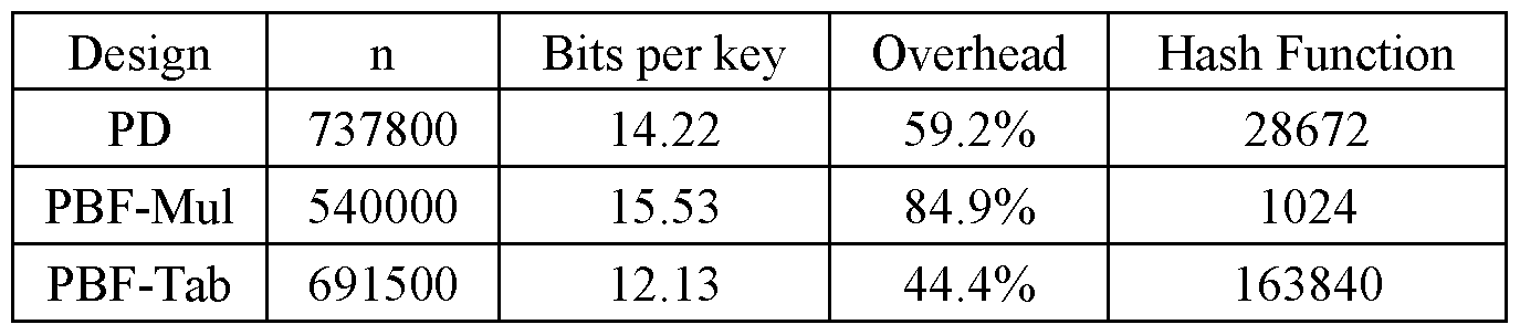
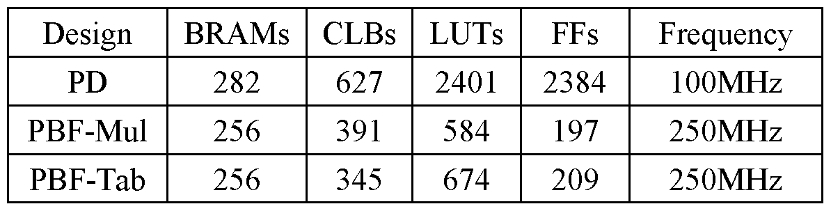


Claims
CLAIMS: 1. A special-purpose digital circuit designed to implement a Fano-Elias (FE) encoding and perform at least one operation over the FE encoding.
2. The special-purpose digital circuit of claim 1 wherein: (a) the operation over the FE encoding is performed using a plurality of sub-operations, and (b) at least some of the sub-operations are performed in parallel on a plurality of sub-circuits comprised within the circuit.
3. The special-purpose digital circuit of claim 2, wherein the operation is performed on a dictionary encoded using FE encoding represented by: (a) a header being an array composed of a plurality of blocks, each associated with a given element quotient and represents the number of occurrences of said element quotient within said dictionary, and (b) a body including an array of values, each representing a given element remainder of a given element found within said dictionary.
4. The special-purpose digital circuit of claim 3, wherein said encoded dictionary is further represented by: (c) a keyed-value array of keyed-values, wherein each of the keyed-values is associated with at least one given element quotient and a given element remainder.
5. The special-purpose digital circuit of claim 3, wherein the element remainder values associated with a given block of the blocks are sorted.
6. The special-purpose digital circuit of claim 5, wherein the element remainder values are sorted by their values.
7. The special-purpose digital circuit of claim 5, wherein the element remainder values are sorted by their access time.
8. The special-purpose digital circuit of claim 3, wherein the element remainder values associated with a given block of the blocks are unsorted.
9. The special-purpose digital circuit of claim 3, wherein the at least one operation over FE encoding is one or more of: an insertion operation for inserting a new element into the dictionary, a query operation for determining if a given element is included in the dictionary, or a deletion operation for deleting an existing element from the dictionary.
10. The special-purpose digital circuit of claim 9, wherein upon the insertion operation being performed on the dictionary when the dictionary is fully stacked, return an indication of a failure.
11. The special-purpose digital circuit of claim 10, wherein a determination that said dictionary is fully stacked is performed by a designated sub-circuit capable of providing such determination.
12. The special-purpose digital circuit of claim 9, wherein upon the deletion operation involves deletion of an element not found within the dictionary, return an indication of a failure.
13. The special-purpose digital circuit of claim 1, wherein a latency of the at least one operation is up to a single clock cycle.
14. The special-purpose digital circuit of claim 9, wherein the query operation includes: receiving a query element including a query element quotient and a query element remainder; concurrently performing: (a) a select sub-operation of the sub-operations, for determining a location of a given block of the blocks associated with a given element quotient identical to said query element quotient, giving rise to a SEL signal, and (b) a compare sub-operation of the sub-operations, during which said query element remainder is compared, concurrently, to the element remainders of said body, so as to determine one or more locations within said body, of remainders identical to said query element remainder, giving rise to a
COMPARE signal indicating locations corresponding to the locations of the remainders that are equal to the query element remainder within said body; aligning the COMPARE signal to the header, giving rise to a PLACE signal; perform a first bitwise logical operation on said PLACE signal and HEADER; giving rise to a MATCH signal; performing a second bitwise logical operation on said SEL signal and the MATCH signal to determine if the query element is within said dictionary; and providing an indication if said query element is within said dictionary, otherwise provide an indication that said query element is not within said dictionary.
15. The special-purpose digital circuit of claim 14, wherein the align is performed by padding the COMPARE signal with a first number of least significant zero bits equal to a first value of the query element quotient, and with a second number of most significant zero bits equal to a number of the plurality of blocks minus the first number.
16. The special-purpose digital circuit of claim 14, wherein said encoded dictionary is further represented by: (c) a keyed-value array of keyed-values, wherein each of the keyed-values is associated with at least one given element quotient and a given element remainder, and wherein upon the indication indicating that the query element is within the dictionary, retrieve the keyed-value associated with the query element quotient and with the query element remainder.
17. The special-purpose digital circuit of claim 9, wherein the delete operation includes: receiving a delete element to be deleted from the dictionary, the delete element including a delete element quotient and a delete element remainder; concurrently performing: (a) a select sub-operation of the sub-operations, for determining a location of a given block of the blocks associated with a given element quotient identical to said delete element quotient, giving rise to a SEL signal, and (b) a compare sub-operation of the sub-operations, during which said delete element remainder is compared, concurrently, to the element remainders
of said body, so as to determine one or more locations within said body, of remainders identical to said delete element remainder, giving rise to a COMPARE signal indicating locations corresponding to the locations of the remainders that are equal to the delete element remainder within said body; aligning the COMPARE signal to the header, giving rise to a PLACE signal; perform a first bitwise logical operation on said PLACE signal and HEADER; giving rise to a MATCH signal; performing a second bitwise logical operation on said SEL signal and the MATCH signal to determine if the delete element is within said dictionary, giving rise to a FIND signal; performing a logical PREFIX-OR operation on the FIND signal, wherein the logical PREFIX-OR operation is designed to convert bits of the FIND signal following a first bit of the FIND signal having the value one to bits having the value one, giving rise to a CONDITIONAL SHIFT header (CSh) signal; updating the header by: (a) shifting the most significant bits of the header, located at locations corresponding to locations having the value one in the CSh signal, to a direction of a least significant bit, and (b) adding a delimiter at a location of the most significant bit; generating a CONDITIONAL SHIFT body (CSb) signal by trimming from the CSh signal the first number of least significant zero bits equal to a first value of the delete element quotient; and updating the body by shifting the most significant bits of the body, located at locations corresponding to locations having the value one in the CSb signal, to the direction of a least significant bit of the body, and assigning a filling value to the most significant bit of the body.
18. The special-purpose digital circuit of claim 17, wherein the align is performed by padding the COMPARE signal with a second number of least significant zero bits equal to the first value, and with a third number of most significant zero bits equal to a number of the plurality of blocks minus the first number.
19. The special-purpose digital circuit of claim 17, wherein said encoded dictionary is further represented by: (c) a keyed-value array of keyed-values, wherein each of the keyed-values is associated with at least one given element quotient and a given element remainder, and delete the keyed-value associated with the delete element quotient and with the delete element remainder from the keyed-value array.
20. The special-purpose digital circuit of claim 9, wherein the insert operation includes: receiving an insert element to be inserted to the dictionary, the insert element including an insert element quotient and an insert element remainder; concurrently performing: (a) a select sub-operation of the sub-operations, for determining a location of a given block of the blocks associated with a given element quotient identical to said insert element quotient, giving rise to a SEL signal, and (b) a compare sub-operation of the sub-operations, during which said insert element remainder is compared, concurrently, by the digital comparators, to the element remainders of said body, so as to determine one or more locations within said body, of remainders greater than said insert element remainder, giving rise to a COMPARE signal indicating locations corresponding to the locations of the remainders that are greater than the insert element remainder within said body; aligning the COMPARE signal to the header, giving rise to a PLACE signal; performing a first bitwise logical operation on said PLACE signal and HEADER; giving rise to a MATCH signal; performing a second bitwise logical operation on said SEL signal and the MATCH signal, giving rise to a FIND signal; performing a logical PREFIX-OR operation on the FIND signal, wherein the logical PREFIX-OR operation is designed to convert bits of the FIND signal following a first bit of the FIND signal having the value one to bits having the value one, giving rise to a CONDITIONAL SHIFT HEADER (CSh) signal; updating the header by shifting the most significant bits of the header, located at locations corresponding to locations having the value one in the CSh signal, to a direction of a most significant bit, and adding a bit having the value
one to a location of the header associated with the location of the first bit having the value one in the CSh signal; generating a CONDITIONAL SHIFT body (CSb) signal by trimming the CSh signal with a first number of least significant zero bits equal to a first value of the insert element quotient; and updating the body by shifting the most significant bits of the body, located at locations corresponding to locations having the value one in the CSb signal, to the direction of a most significant bit, and adding the insert element remainder to a location of the body associated with the location of the first bit having the value one in the CSb signal.
21. The special-purpose digital circuit of claim 20, wherein the aligning is performed by padding the COMPARE signal with a second number of least significant zero bits equal to the first value, and with a third number of most significant zero bits equal to a number of the plurality of blocks minus the first number.
22. The special-purpose digital circuit of claim 20, wherein said encoded dictionary is further represented by: (c) a keyed-value array of keyed-values, wherein each of the keyed-values is associated with at least one given element quotient and a given element remainder, wherein the insert element includes an insert element value, and insert the value associated with the insert element quotient and with the insert element remainder into the keyed-value array.
23. The special-purpose digital circuit of claim 9, wherein the insert operation includes: receiving an insert element to be inserted to the dictionary, the insert element including an insert element quotient and an insert element remainder; performing a select sub-operation of the sub-operations, for determining a location of a given block of the blocks associated with a given element quotient identical to said insert element quotient; updating the header by shifting the most significant bits of the header, starting at a delimiter marking the end of the block associated with the insert element quotient, to a direction of a most significant bit of the header, and
adding a bit having the value one to a least significant bit position at which the shift is applied; updating the body by shifting the most significant bits of the body, located at locations corresponding to locations of the block, starting at the delimiter marking the end of the block, to the direction of a most significant bit of the body, and adding the insert element remainder to a location of the body associated with the locations of the block.
24. The special-purpose digital circuit of claim 1, wherein said circuit is a combinational circuit.
25. The special-purpose digital circuit of claim 2, wherein said sub-circuits include digital comparators.
26. The special-purpose digital circuit of claim 2, wherein said sub-circuits include digital shifters.
27. The special-purpose digital circuit of claim 2, wherein at least one sub- circuit of said sub-circuits is capable of performing at least two operations over the FE encoding.
28. A special-purpose digital circuit configured to perform at least one Fano- Elias (FE) encoding operation, wherein the circuit includes: a. a plurality of digital comparators; b. a plurality of digital shifters; c. a plurality of digital multiplexers capable of performing a shift by one position in any direction; d. a subcircuit that computes a number of identical bit values in a vector of bits; e. a subcircuit that computes a prefix-OR of a vector of bits; and f. a subcircuit that computes a prefix-sum of a vector of bits.
29. A serial dynamic dictionary comprising the special-purpose digital circuit of claim 1 and a memory bank including a plurality of dictionaries, wherein each dictionary is encoded using FE encoding represented by: (a) a respective header being an array composed of a plurality of blocks, each associated with a given element quotient and represents the number of occurrences of said element quotient within said dictionary, and (b) a respective body including an array of values, each representing a given element remainder of a given element found within said dictionary.
30. The serial dynamic dictionary of claim 29, wherein each of the dictionaries is further represented by: (c) a keyed-value array of keyed-values, wherein each of the keyed-values is associated with at least one given element quotient and a given element remainder of the respective dictionary.
31. The serial dynamic dictionary of claim 29, wherein the serial dynamic dictionary comprises a processing circuitry configured to: receive input including (a) an operation over the FE encoding, (b) an index enabling identification of a selected dictionary of the dictionaries, (c) a corresponding element quotient, and (d) a corresponding element remainder; and, perform the operation over the FE encoding on the selected dictionary, retrieved from the memory bank, utilizing the corresponding element quotient, and the corresponding element remainder.
32. The serial dynamic dictionary of claim 31, wherein the input is a result of executing a random hash function on given data.
33. The serial dynamic dictionary of claim 31, wherein the length of the given data is arbitrary.
34. The serial dynamic dictionary of claim 31, wherein the memory bank is stored in a main memory hierarchy.
35. The serial dynamic dictionary of claim 31, wherein a new dictionary operation can be issued every clock cycle.
36. The serial dynamic dictionary of claim 31, wherein an outcome of every query operation is output in up to two clock cycles.
37. A dynamic serial filter comprising at least one dictionary of the serial dynamic dictionary of claim 29, and a processing circuitry configured to: (i) obtain an operation over the FE encoding, and a corresponding element; (ii) hash the element, giving rise to a hashed element including an element quotient and an element remainder; and (iii) perform the operation on the hashed element using the first serial dynamic dictionary of the serial dynamic dictionaries.
38. The dynamic serial filter of claim 37, wherein the dynamic serial filter comprising at least two of the serial dynamic dictionaries of claim 29, and wherein the processing circuitry is further configured to: (iv) upon the serial dynamic dictionary on which the operation was performed on step (iii) being fully stacked, repeat steps (ii) and (iii) on a subsequent serial dynamic dictionary of the serial dynamic dictionaries; and (v) upon the subsequent serial dynamic dictionary being fully stacked, repeat step (iv) until successfully performing the operation.
39. A parallel dynamic filter comprising a plurality of the serial dynamic dictionaries of claim 29, and a processing circuitry configured to: obtain a plurality of operations over the FE encoding, and corresponding elements; hash said elements, given rise to hashed elements, each including an element index, an element quotient and an element remainder; route each given operation of the operations and the corresponding hashed element in accordance with a value of the corresponding hashed element index to a respective serial dynamic dictionary; and perform the given operation on the hashed element using the respective serial dynamic dictionary.
40. The parallel dynamic dictionary of claim 39, wherein each of the dictionaries is further represented by: (c) a keyed-value array of keyed-values, wherein each of the keyed-values is associated with at least one given element quotient and a given element remainder of the respective dictionary.
41. The parallel dynamic filter of claim 39, wherein said element index is composed of a first index directed to enable identification of the respective serial dynamic dictionary and a second index directed to enable identification of the respective dictionary within said memory bank.
42. The parallel dynamic filter of claim 39, further comprising an a- symmetrical First-In-First-Out (FIFO) output queue, wherein the processing circuitry is further configured to: route the results of the performance of the operation from the respective serial dynamic dictionaries into the a-symmetrical FIFO output queue; and serially output the results from the a-symmetrical FIFO output queue.
43. The parallel dynamic filter of claim 39, further comprising a combining element, capable of receiving the plurality of operations and canceling negating operations of the operations, and wherein the processing circuitry is further configured to cancel negating operations of the operations using the combining element before hashing the elements, thereby enabling executing non-negated operations only.
44. The parallel dynamic filter of claim 39, further comprising one or more a-symmetrical First-In-First-Out (FIFO) input queues, each associated with at least one corresponding serial dynamic dictionary, wherein the routing of each given operation of the operations and the corresponding hashed element is performed by inserting the given operation and the corresponding hashed element in accordance with a value of the corresponding hashed element index to a respective a-symmetrical FIFO input queue; and wherein each serial dynamic dictionary serially reads the operation and the corresponding hashed element from the corresponding a-symmetrical FIFO input queue.
45. The parallel dynamic filter of claim 39, further comprising: at least one additional a-symmetrical First-In-First-Out (FIFO) input queue, at least one additional serial dynamic dictionary of claim 29, and wherein the processing circuitry is further configured to: upon the insertion operation of a hashed element is performed on a dictionary being fully stacked, rehash the hashed element, given rise to a rehashed element, and insert the rehashed element into the at least one additional serial dynamic dictionary using the corresponding a-symmetrical First-In-First-Out (FIFO) input queue.
46. The special-purpose digital circuit of claim 9, wherein the delete operation includes: receiving a delete element to be deleted from the dictionary, the delete element including a delete element quotient and a delete element remainder; concurrently performing: (a) a select sub-operation of the sub-operations, for determining a location within a substring of the HEADER of a given block of the blocks associated with a given element quotient identical to said delete element quotient, giving rise to a SEL signal, and (b) a compare sub-operation of the sub-operations, during which said delete element remainder is compared, concurrently with the remainders of said body, so as to determine one or more locations within said body, of remainders identical to said delete element remainder, giving rise to a COMPARE signal indicating locations corresponding to the locations of the remainders that are equal to the delete element remainder within said body; performing a bitwise logical operation on said SEL signal and the COMPARE signal to determine if the delete element is within said dictionary, giving rise to a FIND signal; performing a PREFIX-OR operation on the FIND signal to obtain the CONDITIONAL SHIFT body (CSb) signal; updating the body by shifting the most significant bits of the body, located at locations corresponding to locations having the value one in the CSb signal, to the direction of a least significant bit of the body, and assigning a filling value to the most significant bit of the body;
generating a CONDITIONAL SHIFT header (CSh) signal by appending the first number of least significant zero bits equal to a first value of the delete element quotient to the CSb signal ; and updating the header by: (a) shifting the most significant bits of the header, located at locations corresponding to locations having the value one in the CSh signal, to a direction of a least significant bit, and (b) adding a delimiter at a location of the most significant bit.
47. The serial dynamic dictionary of claim 31, wherein an outcome of every query operation is output with a delay of 3 clock cycles.
Applications Claiming Priority (2)
| Application Number | Priority Date | Filing Date | Title |
|---|---|---|---|
| US202363508303P | 2023-06-15 | 2023-06-15 | |
| US63/508,303 | 2023-06-15 |
Publications (1)
| Publication Number | Publication Date |
|---|---|
| WO2024257084A1 true WO2024257084A1 (en) | 2024-12-19 |
Family
ID=93851551
Family Applications (1)
| Application Number | Title | Priority Date | Filing Date |
|---|---|---|---|
| PCT/IL2024/050529 Ceased WO2024257084A1 (en) | 2023-06-15 | 2024-05-30 | Implementations of fano-elias encoding in hardware |
Country Status (1)
| Country | Link |
|---|---|
| WO (1) | WO2024257084A1 (en) |
Citations (5)
| Publication number | Priority date | Publication date | Assignee | Title |
|---|---|---|---|---|
| US5663721A (en) * | 1995-03-20 | 1997-09-02 | Compaq Computer Corporation | Method and apparatus using code values and length fields for compressing computer data |
| GB2334653A (en) * | 1997-12-20 | 1999-08-25 | Daewoo Electronics Co Ltd | Data compression system with dictionary updating algorithm |
| US20190312589A1 (en) * | 2015-07-03 | 2019-10-10 | Sisp Technologies Ltd. | Data processing method and apparatus |
| US20200336214A1 (en) * | 2019-04-18 | 2020-10-22 | Microsoft Technology Licensing, Llc | Power-based decoding of data received over an optical communication path |
| US20210144405A1 (en) * | 2017-04-28 | 2021-05-13 | Ascava, Inc. | Lossless reduction of data by using a prime data sieve and performing multidimensional search and content-associative retrieval on data that has been losslessly reduced using a prime data sieve |
-
2024
- 2024-05-30 WO PCT/IL2024/050529 patent/WO2024257084A1/en not_active Ceased
Patent Citations (5)
| Publication number | Priority date | Publication date | Assignee | Title |
|---|---|---|---|---|
| US5663721A (en) * | 1995-03-20 | 1997-09-02 | Compaq Computer Corporation | Method and apparatus using code values and length fields for compressing computer data |
| GB2334653A (en) * | 1997-12-20 | 1999-08-25 | Daewoo Electronics Co Ltd | Data compression system with dictionary updating algorithm |
| US20190312589A1 (en) * | 2015-07-03 | 2019-10-10 | Sisp Technologies Ltd. | Data processing method and apparatus |
| US20210144405A1 (en) * | 2017-04-28 | 2021-05-13 | Ascava, Inc. | Lossless reduction of data by using a prime data sieve and performing multidimensional search and content-associative retrieval on data that has been losslessly reduced using a prime data sieve |
| US20200336214A1 (en) * | 2019-04-18 | 2020-10-22 | Microsoft Technology Licensing, Llc | Power-based decoding of data received over an optical communication path |
Non-Patent Citations (3)
| Title |
|---|
| Implementation of Huffman Decoder on FPGA .Int. Journal of Engineering Research and Applications www.ijera.com ISSN: 2248-9622, Vol. 6, Issue 1, (Part - 3) January 2016, pp.84-88 (Retrieved on 07-10-2024). Retrieved from the internet: <https://d1wqtxts1xzle7.cloudfront.net/47558419/L61038488-libre.pdf?1469617745=&response-content-disposition=inline%3B+filename%3DImplementation_of_Huffman_Decoder_on_Fpg.pdf&Expires=1720532192&Signature=KSUkO1pftQtajusC8EahRC-JPmeSoy5CFtGWDLaXwX5YnwcqSHYMXz37ts1a4PuC5ZSB~4O3vEm9ujQw0eRoyuCTXLYSHLl7bgx9n29vw2ZMK6FIY9cnVa5DtOyDQNlNgRMn6v51q-ARuDPZXAExoQtXV3MeIGgXldGhr~M1PG2CAXrJj4rV5QKq60xQF0gx-Qfyje7yjsrwF~rDMNkejtEhtNkliByEpKYPuyucosugnIQ1MM5D-bMLykLgwaRa5D~fh8ZixOMRPHLq8XwOuvOD3NKLhVGo4zGrdTTZTL89faLn71cal8d1rLZ1vp8y2J6T2L14CvdNf11Yxtq2Tw__&Key-Pair-Id=APKAJLOHF5GGSLRBV4ZA> DAHRI et al (2016/01/31) * |
| IOANA O. BERCEA; GUY EVEN: "Fully-Dynamic Space-Efficient Dictionaries and Filters with Constant Number of Memory Accesses", ARXIV.ORG, CORNELL UNIVERSITY LIBRARY, 201 OLIN LIBRARY CORNELL UNIVERSITY ITHACA, NY 14853, 12 November 2019 (2019-11-12), 201 Olin Library Cornell University Ithaca, NY 14853 , XP081531036 * |
| Parallel Huffman decoder with an optimized look up table option on FPGA. (2000). (Vol. 1, pp. 73-76). IEEE.(Retrieved on 08-10-2024). Retrieved from the internet: <https://web.archive.org/web/20171110041904id_/https://core.ac.uk/download/pdf/11778855.pdf> ASPAR, Z., et al. (2024/02/28) * |
Similar Documents
| Publication | Publication Date | Title |
|---|---|---|
| US11762828B2 (en) | Cuckoo filters and cuckoo hash tables with biasing, compression, and decoupled logical sparsity | |
| US11899641B2 (en) | Trie-based indices for databases | |
| US10705735B2 (en) | Method and device for managing hash table, and computer program product | |
| US10387397B2 (en) | Parallel build of non-partitioned join hash tables and non-enforced n:1 join hash tables | |
| US9495398B2 (en) | Index for hybrid database | |
| US10545865B2 (en) | Systems and methods for implementing low-latency lookup circuits using sparse hash functions | |
| US20150058595A1 (en) | Systems and Methods for Implementing Dynamically Configurable Perfect Hash Tables | |
| US10735026B2 (en) | Compression and decompression engines and compressed domain processors | |
| US20130268770A1 (en) | Cryptographic hash database | |
| Ružić | Constructing efficient dictionaries in close to sorting time | |
| US20150121034A1 (en) | Systems and Methods for Implementing Low-Latency Lookup Circuits Using Multiple Hash Functions | |
| US12032548B2 (en) | System and method for self-resizing associative probabilistic hash-based data structures | |
| Liu et al. | Succinct filters for sets of unknown sizes | |
| US10078646B2 (en) | Hardware efficient fingerprinting | |
| US9292549B2 (en) | Method and system for index serialization | |
| Li et al. | Dynamic dictionary with subconstant wasted bits per key | |
| WO2025001902A1 (en) | Skiplist-based data read-write method, system, device and storage medium | |
| CN101140593A (en) | A keyword matching method and system | |
| KR20180080684A (en) | Method and system of searching for data stored in memory | |
| US11139828B2 (en) | Memory compression method and apparatus | |
| US9400817B2 (en) | In-place index repair | |
| CN110321346B (en) | Method and system for realizing character string hash table | |
| US10547325B2 (en) | Area efficient decompression acceleration | |
| US11604603B2 (en) | Method and system for persistent partitionable distributed map using sparse arrays and sparse ordered two-bit bitmaps in shared memory | |
| Even et al. | Brief announcement: a parallel architecture for dynamic approximate membership |
Legal Events
| Date | Code | Title | Description |
|---|---|---|---|
| 121 | Ep: the epo has been informed by wipo that ep was designated in this application |
Ref document number: 24822966 Country of ref document: EP Kind code of ref document: A1 |
|
| NENP | Non-entry into the national phase |
Ref country code: DE |
|
| 122 | Ep: pct application non-entry in european phase |
Ref document number: 24822966 Country of ref document: EP Kind code of ref document: A1 |