WO2024256220A1 - Quantum bernoulli factory photonic circuit independent of input state bias - Google Patents
Quantum bernoulli factory photonic circuit independent of input state bias Download PDFInfo
- Publication number
- WO2024256220A1 WO2024256220A1 PCT/EP2024/065333 EP2024065333W WO2024256220A1 WO 2024256220 A1 WO2024256220 A1 WO 2024256220A1 EP 2024065333 W EP2024065333 W EP 2024065333W WO 2024256220 A1 WO2024256220 A1 WO 2024256220A1
- Authority
- WO
- WIPO (PCT)
- Prior art keywords
- photon
- output
- qubit
- sum
- interferometer
- Prior art date
- Legal status (The legal status is an assumption and is not a legal conclusion. Google has not performed a legal analysis and makes no representation as to the accuracy of the status listed.)
- Ceased
Links
Classifications
-
- G—PHYSICS
- G06—COMPUTING OR CALCULATING; COUNTING
- G06F—ELECTRIC DIGITAL DATA PROCESSING
- G06F7/00—Methods or arrangements for processing data by operating upon the order or content of the data handled
- G06F7/38—Methods or arrangements for performing computations using exclusively denominational number representation, e.g. using binary, ternary, decimal representation
- G06F7/48—Methods or arrangements for performing computations using exclusively denominational number representation, e.g. using binary, ternary, decimal representation using non-contact-making devices, e.g. tube, solid state device; using unspecified devices
- G06F7/544—Methods or arrangements for performing computations using exclusively denominational number representation, e.g. using binary, ternary, decimal representation using non-contact-making devices, e.g. tube, solid state device; using unspecified devices for evaluating functions by calculation
-
- G—PHYSICS
- G06—COMPUTING OR CALCULATING; COUNTING
- G06E—OPTICAL COMPUTING DEVICES
- G06E3/00—Devices not provided for in group G06E1/00, e.g. for processing analogue or hybrid data
- G06E3/001—Analogue devices in which mathematical operations are carried out with the aid of optical or electro-optical elements
-
- G—PHYSICS
- G06—COMPUTING OR CALCULATING; COUNTING
- G06N—COMPUTING ARRANGEMENTS BASED ON SPECIFIC COMPUTATIONAL MODELS
- G06N10/00—Quantum computing, i.e. information processing based on quantum-mechanical phenomena
Definitions
- Quantum Bernoulli Factory photonic circuit independent of input state bias ------ Applicants: Università degli Studi di Roma “La Sapienza” (70%) International Iberian Nanotechnology Laboratory (20%), Consiglio Nazionale delle Ricerche (10%) Inventors: Ernesto Fagundes Galv ⁇ o (INL, 20%), Fabio Sciarrino (Sapienza Università di Roma, 15%), Gonzalo Alfredo Carvacho Vera (Sapienza Università di Roma, 15%), Francesco Hoch (Sapienza Università di Roma, 15%), Nicol ⁇ Spagnolo (Sapienza Università di Roma, 14%), Roberto Osellame (CNR-IFN, 10%), Taira Giordani (Sapienza Università di Roma, 6%), Luca Castello (Sapienza Università di Roma, 5%) ------ The present invention concerns a Quantum Bernoulli Factory photonic circuit independent of input state bias.
- Quantum Information exploits the peculiarity of quantum effects as a new computational resource for faster computation, to enable unbreakable cryptographic protocols and to increase communication efficiency in distributed computational problems.
- Randomness plays an essential role in several research fields and numerous applications of information technology. Quantum mechanics gives access to genuine randomness based on the intrinsic random behavior of its measurement process. This peculiar property of quantum theory leads to numerous advantages in information manipulation, communication and processing, which have been exploited in various quantum communication protocols and quantum computing algorithms.
- the generation and manipulation of quantum randomness has been studied in depth and widely implemented using different platforms, single photon properties and protocols. Random number handling is fundamental for statistical methods and computation. An interesting paradigm in this area are the so-called Bernoulli factories.
- randomness processing protocols that take as inputs random variables such as a coin with some bias, and change the bias in a well-defined way, which is independent of the bias.
- the Bernoulli Factory concept addresses the problem of how to construct a variable distributed according to a Bernoulli distribution (an unbalanced coin), having access to another Bernoulli variable of unknown bias, aiming to obtain a certain functional relationship between the input and output distributions.
- a Classical-to-Classical Bernoulli Factory CCBF
- both input and output are classical variables, finding applications in a wide range of fields ranging from Monte-Carlo simulation of Markov chains [2] to economy [3].
- the space of simulable functions has been characterized, however a general method to be able to build them efficiently has not been found yet.
- Bernoulli Factories have proved useful for improving the performance of the Markov Chain Monte Carlo (MCMC) method, used to sample from complex probability distributions, as required for some simulation methods.
- Bernoulli Factories can be used to avoid the need for a long burn-in period required in the process MCMC to sample from a good approximation of the target distribution [4].
- Bernoulli factories have been used in simulations, for example of ocean currents [5], as well as in economics and game theory [6, 3].
- Ref. [12] uses entangled photons as primary resource, which is however impossible to be employed in a subsequent step due to the performed measurement.
- Ref. [13] the two input qubits are codified in different degrees of freedom of the same photon, and hence performing concatenation of multiple requires knowledge on the output state after the first step, which is forbidden by the protocol. Coding of a Bernoulli Modularity Concaten. qubit on a Information Linear Factory of the of single coding optics model scheme operations photon Ref. Polarization QQBF X X [13] and dual-rail Ref.
- Quantum Bernoulli Factory turns out to be a general answer to the problem of generating new random variables both classical, like a random bit, and quantum, i.e. qubits, two- level quantum systems, quantum equivalents of bits.
- the potential advantages of the Quantum Bernoulli Factory are therefore wide-ranging and concern: 1.
- Constructible functions for classical random variables we mean the transformations that operate on random variables with an unknown distribution to generate new ones. It has been shown that the class of functions constructible by a Quantum Bernoulli Factory is strictly larger than the functions constructible by the classical Bernoulli Factory. 2. Computational advantage – For the same function, the quantum version requires on average a smaller number of extractions. This implies that the use of a quantum system in the implementation of a Bernoulli Factory reduces the consumption of resources if this is compared with its classical equivalent. 3. Exact method – The Quantum Bernoulli Factory applies the required transformation exactly; its application does not need to introduce computational or approximation errors.
- Quantum Bernoulli Factory offers benefits in the following scenarios: 1. Sampling algorithm subroutines. These algorithms aiming to sample from an unknown distribution, the most famous examples being the Markov Chain Monte Carlo methods, can benefit from the sampling properties of the Bernoulli Factory. 2. Quantum algorithm subroutines – Given the quantum nature of the method in both input and output this approach can be used as a basis function for more complex quantum programs. 3.
- Quantum Bernoulli Factory The distinctive property of the Quantum Bernoulli Factory is that it does not require knowledge of the probability distribution that governs the random variable of entrance. This makes it particularly useful in encryption protocols where it is generally necessary to process encrypted message strings for which it is not possible to know the probability distribution that determines their encryption, both in a quantum and traditional context. 4. Scenarios with multiple customers. The concept of the QQBF can be extended in the more general scenario of multiple users, i.e. the condition in which the factory takes as input several quoins. This formulation finds further application in quantum computing, more specifically in the framework of blind quantum computing [14].
- the development of the quantum technology market is strongly moving towards a "cloud computing" style approach, which must use NISQ (Noisy Intermediate-Scale Quantum) technology currently available in quantum computing.
- NISQ Noisy Intermediate-Scale Quantum
- the object of the present invention is to provide a Quantum-to-Quantum Bernoulli Factory method that solve the problems and overcome the disadvantages of the prior art.
- the subject-matter of the present invention is a Quantum-to-Quantum Bernoulli Factory method according to the attached claims.
- ⁇ Fig.1 shows different types of Bernoulli Factories according to the prior art: (a) Classical-to-Classical Bernoulli Factory (CCBF) where a sequence of classical bits with unknown bias p are processed to produce a new coin with bias f(p); (b) Quantum-to-Classical Bernoulli Factory (QCBF) in which a quantum coin (Quoin) encodes the input bias in quantum amplitudes, with the goal of generating classical coins with a different bias; (c) Quantum-to-Quantum Bernoulli Factory (QQBF) where both the input and output are quantum states; ⁇ Fig.
- CCBF Classical-to-Classical Bernoulli Factory
- QBF Quantum-to-Classical Bernoulli Factory
- QQBF Quantum-to-Quantum Bernoulli Factory
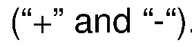
- FIG. 2 shows the block scheme of the Modular Optical Quantum Bernoulli Factory (MOQBEF) with reference to the creation and annihilation operators for the electromagnetic field modes, and to the corresponding logical encoding for the qubits in the computational basis (
- MOQBEF Modular Optical Quantum Bernoulli Factory
- the annihilation and creation operators refer to generic modes of the electromagnetic fields, and can correspond to any possible choice of degree of freedom for qubit encoding, thus independent from the specific implementation;
- (a) Inversion operation is performed by applying a suitable transformation ⁇ ⁇ ⁇ ⁇ ⁇ ⁇ ⁇ ⁇ ⁇ ⁇ ⁇ ⁇ to the input qubit;
- (b) Product operation is obtained by applying a suitable transformation ⁇ ⁇ ⁇ ⁇ ⁇ ⁇ ⁇ ⁇ ⁇ ⁇ ⁇ ⁇ to the four input modes, which correspond to two input qubits when one photon is present in each mode pair, and conditioned to the detection of one photon in output +;
- (c) Sum operation is obtained by applying a suitable transformation ⁇ ⁇ ⁇ ⁇ to the four input modes, which corresponds to two input qubits when one photon is present in each mode pair, and conditioned to the detection of one photon in output S;
- FIG. 3 shows building blocks for a polarization implementation according to the present disclosure.
- the inputs of the interferometers are labeled by numbers 1 and 2, while the output is labeled as out;
- Inversion operation is performed by propagation of the input qubit through a half-wave plate with optical axis oriented at an angle of ⁇ /4 to the horizontal axis.
- Product operation is performed by applying a set of phase shifts on the input photons, different for each polarization state, by injecting them in the two input ports of a polarizing beam splitter, and post-selecting the events for which one photon exits from each port.
- One of the outputs propagates through a half-wave plate with optical axis rotated by ⁇ /8 with respect to the horizontal one, followed by two phase shifts different for each polarization state, and a measurement in the computational basis.
- the other photon is in the product or in the anti-product state;
- the sum operation is performed by making two photons interfere in a partially-polarizing beam splitter after application of a set of two phase shifts on the input photons, different for each polarization state, and post-selecting the events where the two photons exit from different ports.
- the input ports of the interferometers are labelled 1 and 2, with outputs labelled out: (a) Inversion is performed deterministically by swapping the dual-rail modes; (b) The product is performed by applying a set of phase shifts ( ⁇ 1 , ⁇ 2 , ⁇ 3 , ⁇ 4 ) on the input components of the qubits, by sending the component 1 ⁇ of dual-rail qubit 1 and component 0 ⁇ of dual-rail qubit 2 into a balanced beam-splitter, by applying two phase shifts ( ⁇ 2 , ⁇ 3 ) on the output modes of the beam- splitter, and post-selecting events with one of the two photons in output ports - or + in the figure.
- the state prepared by this measured event is encoded in an output dual-rail qubit labelled out; (c) The sum is implemented by swapping the input mode component 1 ⁇ of dual- rail qubit 1 and component 0 ⁇ of dual-rail qubit 2, by applying a set of phase shifts ( ⁇ 1 , ⁇ 2 , ⁇ 3 , ⁇ 4 ) on the input components of the qubits, by directing the modes in two beam-splitters, and by applying a second set of phase shifts ( ⁇ 1 , ⁇ 2 , ⁇ 3 , ⁇ 4 ) on the output modes.
- the operation is successful when a photon is detected by the detector labelled “S”; ⁇ Fig.
- Thermo- optic effect devices can control the reflectivities of the beam-splitters in panel a, as well as the phase shifters represented by rectangles in the schematic.
- the beam-splitters with tunable beam-splitting ratios can be implemented via a Mach-Zehnder interferometer featuring two 50/50 beam-splitters and a phase shifter in between (inset b);
- ⁇ Fig.9 shows a configuration for the implementation of the building blocks of the MOQBEF in a 6-mode reprogrammable interferometer, according to an embodiment of the disclosure.
- ⁇ Fig. 10 shows concatenations of two operations in the MOQBEF encoded in a 6-mode reprogrammable interferometer, according to an embodiment of the disclosure.
- z 4 ⁇
- z 1 z 2 + z 3 ⁇ is encoded in the modes 3-4 when the other two photons are detected in the mode pairs (1,5), (2,6); and ⁇ Fig.
- FIG. 11 shows an example of a MOQBF acting on 5 dual-rail path encoded qubits, according to an embodiment of the disclosure.
- This photonic circuit implements the following function:
- z ⁇
- the disclosure provides for an implementation using a quantum photonic system that can take advantage of the different information coding approaches using states of single photons.
- the validity of the proposed scheme has already been experimentally verified by the Inventors in an integrated and fully reconfigurable photonics platform. Let us therefore examine in detail the various characteristics of the disclosure.
- MOQBEF Modular Optical Quantum Bernoulli Factory
- the MOQBEF fits fully into the framework of NISQ (Noisy Intermediate-Scale Quantum) technologies.
- time in this case the two basic quantum states
- the MOQBEF provides different solutions to the problems and limitations of the prior art. In fact, it first solves the problem of modularity, i.e. the possibility of implementing both individually and in combination the 3 fundamental blocks that implement the single field operations. This makes it possible to implement the entire spectrum of functions that can be constructed from a Quantum-to-Quantum Bernoulli factory. Finally, these functions are applied to the state’s random input without the requirement to know the original probability distribution. The latter property is essential for a genuine creation of a Quantum-to-Quantum Bernoulli Factory.
- the MOQBEF exploits a photonic platform that has been greatly developed in recent years, and offers technological advantages provided by encoding quantum systems in single photon states.
- they can be processed using linear optical elements, such as waveplates and semi-reflecting mirrors for bulk optics setup, or waveguides with directional couplers and controlled phase delays for integrated photonics.
- the photonic states generated by the MOQBEF will also be able to be distributed among multiple parties and customers, using traditional fiber optic signal transmission channels.
- Other possible choices of the encodings include orbital angular momentum, associated to the spatial and phase field distribution, or frequency-based encoding. Orbital angular momentum can be manipulated via several devices, including vortex plates, q-plates and spatial-light modulators.
- Frequency encoding is based on assigning the qubit logical values
- the technical characteristics of the three possible photonic encodings of the MOQBEF are analyzed below. First of all, it is necessary to formally define the operations of the MOQBEF.
- the input variable of a MOQBEF is a quantum state of the type where ⁇ can be either a real or a complex number.
- the inversion operation ( Figure 2(a)) is a single-photon transformation, and is obtained by applying a suitable unitary transformation, that we label as ⁇ ⁇ ⁇ ⁇ ⁇ ⁇ ⁇ ⁇ ⁇ ⁇ ⁇ ⁇ ⁇ ⁇ , on the input modes.
- a suitable unitary transformation that we label as ⁇ ⁇ ⁇ ⁇ ⁇ ⁇ ⁇ ⁇ ⁇ ⁇ ⁇ ⁇ ⁇ ⁇ ⁇
- the product and sum operations require two input photons, and are obtained ( Figure 2(b-c)) after application of suitable unitary transformations, that we label as ⁇ ⁇ ⁇ ⁇ ⁇ ⁇ ⁇ and ⁇ ⁇ ⁇ ⁇ respectively, and conditioned to the detection of one photon in one specific output (labeled as + for the product in panel b, and as S for the sum in panel c).
- each block is implemented via a transformation acting on the exact number of modes corresponding to the number of qubits (2 modes for each qubit). This corresponds to the requirement that the blocks perform linear unitary operations.
- the functions realized by the various blocks are as follows.
- the transformation ⁇ ⁇ ⁇ ⁇ ⁇ ⁇ ⁇ ⁇ ⁇ ⁇ ⁇ ⁇ ⁇ ⁇ ⁇ ⁇ ⁇ ⁇ to be applied on the input modes can be derived by considering the input state
- ⁇ ⁇ and a 2 ⁇ 2 unitary evolution ⁇ , with matrix elements ⁇ ⁇ ⁇ , acting linearly on the creation and annihilation mode operators according to ⁇ ⁇ ⁇ ⁇ ⁇ ⁇ ⁇ ⁇ ⁇ ⁇ ⁇ ⁇ ⁇ , where ⁇ ⁇ ⁇ ⁇ are the mode operators after the action of the transformation, and are the mode operators before the transformation.
- the necessary transformation to obtain the inversion requires to exchange the input modes, thus corresponding to a logical exchange of the basis states of the qubit (
- 1 ⁇ ⁇ ), and thus has the following form: ⁇ ⁇ ⁇ ⁇ ⁇ ⁇ ⁇ ⁇ ⁇ ⁇ ⁇ ( 0 1 1 0 )
- the transformation ⁇ ⁇ ⁇ ⁇ ⁇ ⁇ ⁇ ⁇ ⁇ to be applied on the input modes can be derived by considering two input states
- ⁇ 2 ⁇ , according to Figure 2b, and a 4 ⁇ 4 unitary evolution ⁇ , with matrix elements ⁇ ⁇ ⁇ , acting linearly on the creation and annihilation mode operators according to ⁇ ⁇ ⁇ ⁇ ⁇ ⁇ ⁇ ⁇ ⁇ ⁇ ⁇ ⁇ ⁇ , where ⁇ ⁇ ⁇ ⁇ are the mode operators after the action of the transformation, and ⁇ ⁇ ⁇ ⁇ ⁇ are the mode operators before the transformation.
- a use of more modes is still possible by expanding the space of modes by introducing modes which do not correspond to photons at the input of the function (therefore more inputs where no photons are provided).
- the same procedure can be obtained for the sum operation.
- the transformation ⁇ ⁇ ⁇ ⁇ to be applied on the input modes can be derived by considering two input states
- ⁇ 2 ⁇ , according to Figure 2c, and a 4 ⁇ 4 unitary evolution ⁇ , with matrix elements ⁇ ⁇ ⁇ , acting linearly on the creation and annihilation mode operators according to ⁇ ⁇ ⁇ ⁇ ⁇ ⁇ ⁇ ⁇ ⁇ ⁇ ⁇ ⁇ ⁇ , where ⁇ ⁇ ⁇ ⁇ are the mode operators after the action of the transformation, are the mode operators before the transformation.
- the matrix ⁇ can be further simplified as: Given the unitarity of the matrix, this transformation can be parameterized as: with 0 ⁇ ⁇ 1 , ⁇ 2 ⁇ ⁇ /2 and 0 ⁇ ⁇ 1 , ... , ⁇ 6 ⁇ 2 ⁇ .
- the two quantum levels correspond to two orthogonal polarization states as
- 0 ⁇
- 1 ⁇
- the generic input is then encoded as
- ⁇ ⁇
- the building blocks for the polarization implementation of MOQBEF are depicted in Figure 3.
- the inputs of the interferometers are labeled by numbers 1 and 2, while the output is labeled as out.
- operation block (a) the inversion operation is performed by propagation of the input qubit through a half-wave plate with optical axis oriented at an angle of ⁇ /4 to the horizontal axis.
- the product operation is performed by applying phase shifts ( ⁇ 1 ⁇ , ⁇ 1 ⁇ ) on the two polarization states of photon 1, and phase shifts ( ⁇ 2 ⁇ , ⁇ 2 ⁇ ) on the two polarization states of photon 2. Then, the two photons are injected in the two input ports of a polarizing beam splitter (PBS), and post-selecting the events for which one photon exits from each port.
- PBS polarizing beam splitter
- One of the outputs propagates through a half-wave plate with optical axis rotated by ⁇ /8 with respect to the horizontal one, followed by two phase shifts ( ⁇ 3 ⁇ , ⁇ 3 ⁇ ) acting on the two polarization states, a PBS and photodetectors configured to measure the output in the computational basis.
- the other photon on output port out is in the product (
- the addition operation is performed by applying phase shifts ( ⁇ 1 ⁇ , ⁇ 1 ⁇ ) on the two polarization states of photon 1, and phase shifts ( ⁇ 2 ⁇ , ⁇ 2 ⁇ ) on the two polarization states of photon 2. Then, the two photons interact in a partially-polarizing beam splitter (PPBS), that is, a beam-splitter with different reflectivities ⁇ ⁇ and ⁇ ⁇ for the two polarizations, and the output is post-selected on events where the two photons exit from different ports.
- PPBS partially-polarizing beam splitter
- phase shifts ( ⁇ 0 ⁇ , ⁇ 0 ⁇ ) on the two polarization states of the photon present in output mode out, and phase shifts ( ⁇ 3 ⁇ , ⁇ 3 ⁇ ) on the two polarization states of the photon present in the other output port of the PPBS a polarizing beam splitter is applied to measure the second one.
- the photon on mode out will be found in the “sum” (
- the Inversion operation will thus be the operation that transforms the polarization state from
- phase shifts can all (or in part) set to zero, and therefore there will be a device with a reduced number of components.
- Inversion operation can be directly implemented via application of a “swap” operation on the states:
- the Inversion operation can be implemented by using a half wave-plate with an optical axis rotated by an angle of ⁇ /4 with respect to the horizontal plane (another implementation could be a liquid crystal). This corresponds to the application of the “swap” operation in the polarization degree of freedom. This operation is performed with success probability equal to 1.
- the product operation between two states is defined as follows: This operation is obtained by injecting the two photons in the two input ports of a polarizing beam splitter (see Figure 3(b)) after applications of input phase shifts ( ⁇ 1 ⁇ , ⁇ 1 ⁇ ) and ( ⁇ 2 ⁇ , ⁇ 2 ⁇ ).
- the scheme operates in post- selection, and thus we accept only the events in which the two photons exit from the different output ports of the first PBS.
- we apply a half- wave plate with an optical axis rotated by an angle of ⁇ /8 with respect to the horizontal direction we apply the two phase-shifts ( ⁇ 3 ⁇ , ⁇ 3 ⁇ ), and we measure the polarization of the second photon.
- the output state is the product (
- the output state is anti-product of the inputs.
- the two input photons are injected in the two input ports of a partially-polarizing beam-splitter after a set of phase shifts ( ⁇ 1 ⁇ , ⁇ 1 ⁇ , ⁇ 2 ⁇ , ⁇ 2 ⁇ ), different for the horizontal and vertical polarization states, is applied.
- the requested operation is performed when the two photons exit from different outputs of the PPBS.
- a second set of phase shifts ( ⁇ 0 ⁇ , ⁇ 0 ⁇ , ⁇ 3 ⁇ , ⁇ 3 ⁇ ), different for the horizontal and vertical polarization states, is then applied on the two output photons.
- a polarizing beam- splitter is inserted to measure the polarization state of one of the photons.
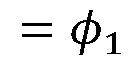
- the system performs two different operations. More specifically, the sum (the arithmetic mean) is obtained when the measured photon is found in the
- 1 2 ⁇ 1 + ⁇ 2 ⁇ is obtained when the measured photon is found in the
- the success probabilities of the two operations are given by the following expressions: and
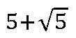
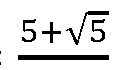
- 2 ⁇ ⁇ 1 2 1 ⁇ 2 5 (1 +
- the scheme described above can be concatenated to obtain an arbitrary sequence of operations. This can be done by taking the output of a specific step and using it as the input of the subsequent step.
- the operation ⁇ ⁇ 1 + ⁇ 2 + ⁇ 3 is performed by the following steps: (i) prepare two qubits in the states
- the same approach can be applied to arbitrary combinations thanks to the independence of the building blocks from the state of the qubits to be processed.
- the success probability for an arbitrary concatenation of ⁇ operations will be the product of the individual success probabilities of each operation.
- additional qubits should be prepared for each product/sum operation included in the chain, since the sum and the product consume one qubit (as one photon is absorbed by a photodetector).
- Time photonic operations In this encoding the two quantum levels correspond to two different pulses separated by a time ⁇ greater than the coherence time of the photons.
- the coherence time is the time over which a propagating wave (especially a laser or maser beam) may be considered coherent, meaning that its phase is, on average, predictable.
- the coherence time may be reduced by propagation factors such as dispersion, scattering, and diffraction (the coherence time is set to be equal for the two photons).
- This condition on ⁇ is necessary to ensure that the two states encoded in the pulses at time ⁇ 1 and ⁇ 2 individuate a two-level system for qubits.
- the time-polarization encoder and decoder are shown in Figure 4.
- the time-encoded state enters the upper branch of the interferometer where an electro-optical modulator (EOM) applies a bias rotation only on the second pulse (see Figure 4(a)).
- EOM electro-optical modulator
- This operation allows the division of the two pulses after the first polarizing beam-splitter.
- the first pulse is reflected on the upper branch of the interferometer while the second pulse is transmitted on the lower branch of the interferometer.
- a delay line (DL) applied to the upper branch synchronizes the two pulses, i.e. compensates for the time interval ⁇ between the two pulses.
- the second polarizing beam-splitter combines together the two pulses which will be synchronized but with orthogonal polarization states.
- the reverse operation is performed by the interferometer shown in Figure 4(b).
- Path-photonic operations Path encoding was the one investigated for the realization of a MOQBEF prototype according to the present disclosure. More specifically, in this encoding the two quantum levels correspond to the presence of a photon in one of two different paths. As an example, in Figure 5(a) the logical state
- Such an encoding is the optimal choice for information processing on compact devices such as integrated reprogrammable photonic chips.
- the path degree of freedom is particularly suitable when using integrated optics, making it easier to implement larger and stable interferometers.
- the details of the optical elements necessary to perform the three elementary operations of the MOQBEF on the paths are reported in detail in Figure 5.
- the input ports of the interferometers are labelled 1 and 2, with outputs labelled out.
- the product is performed by applying a set of input phase shifts ( ⁇ 1, ⁇ 2, ⁇ 3, ⁇ 4), by sending component
- the state prepared by this measured event is encoded in an output dual-rail qubit labelled out.
- the sum is implemented by swapping the input mode component
- the operation is successful when a photon is detected by the detector labelled “S”.
- the success operation is exactly the same of the implementation of Figure 2. We describe below the working principles of this approach.
- phase shifts can all (or in part) set to zero, and therefore there will be a device with a reduced number of components, except for a few phases that will be specified below.
- Inversion operation To implement the inversion we use the operation implemented by exchanging the modes in the interferometer, as in Figure 5(a). It corresponds to a direct swap of the optical modes. Analogously to the case of polarization encoding, this operation can be carried out deterministically without any qubit measurement and thus the success probability is 1.
- Product operation The block scheme presented in Figure 5(b) implements the product operation between two qubits. First, a set of input phase shifts ( ⁇ 1 , ⁇ 2 , ⁇ 3 , ⁇ 4 ), is applied on the input modes.
- 0 ⁇ ⁇ 2 of qubit 2 are coupled to the two input ports of a balanced beam-splitter. After applying two phase shifts ( ⁇ 2 , ⁇ 3 ), the two output ports of this element are measured with single- photon detectors as shown in the Figure . The final state of the qubit encoded in the remaining two modes, depends on the presence of a single photon in one of the two outputs of the beam-splitter.
- the expression of the output qubit is: where the sign ⁇ will depend on which detector signals the presence of a photon.
- T he probability of success is found to be within the range [0, 0.5] and is > 0 everywhere except for the pair of states (
- Addition/sum operation The interferometer of Figure 5(c) implements the sum operation between two qubits. First, the modes corresponding to level
- the sum operation is performed when one photon is detected at the output marked as “S”.
- the state of the sum qubit is: where ⁇ and ⁇ are the reflectivity and transmissivity of the beamsplitters, and ⁇ is the normalization factor.
- the harmonic mean operation is performed, and the corresponding state is:
- the probability to detect one photon in “S” is then given by: It represents the success probability of the sum operation.
- the probability to find one photon in “I” is given by:
- the success probability is > 0 everywhere except for the states (
- Orbital angular momentum operations In this encoding, the two quantum levels correspond to two different eigenstates of the orbital angular momentum (OAM) operator of the electromagnetic field. Examples of such states are the Laguerre Gauss (LG) modes, a family of solutions of the Helmholtz equation.
- a light beam that carries OAM means that has an helicoidal wavefront.
- the value of OAM corresponds to the windings number of the optical phase of the wavefront in the transverse plane.
- the OAM can assume only integer values.
- a qubit state is encoded by considering two different values and ⁇ 2 of the OAM.
- the OAM-path encoder and decoder shown schematically in Figure 6, are based on a device called OAM-sorter.
- the OAM-sorter displaces the two states
- ⁇ 1 ⁇
- ⁇ 2 ⁇
- An example of such a device can be found in Ref. [16].
- the reverse operation is performed by another OAM-sorter that takes as input the path photonic qubit such as the output of the path-encoded MOQBEF and converts the information in the OAM logical states.
- the respective qubits in the first photon and the second photon are encoded in their orbital angular momentum, OAM as follows: ⁇ a first OAM-sorter for the first photon qubit and a second OAM-sorter for the second photon qubit are provided and configured to convert the OAM-based qubits into path-encoded qubits; ⁇ the multiplication interferometer and the sum interferometer as above described are provided, which take as inputs the path-encoded qubits; ⁇ a third OAM sorter is provided and configured to convert the output path-encoded qubit of step B into OAM-based qubit as follows: ⁇ the third OAM-sorter is configured to take the output modes from the multiplication interferometer as inputs; ⁇ the third OAM-sorter is configured to take the output modes from the sum interferometer as inputs.
- the two quantum levels are two well separated optical frequencies and ⁇ 2 .
- the difference ⁇ ⁇ between them is greater than the spectral width of the two individual frequencies.
- To carry out the operations necessary to implement a Bernoulli factory in this degree of freedom it is possible to make use of a converter from frequency-bin encoding and path encoding and vice versa. This allows us to use the path-encoded operations described above.
- the frequency-path encoder and decoder are based on a device able to mix different frequency components and ⁇ 2 .
- Such a beam-splitter operation can be performed with a scheme called quantum frequency processor (QFP) described in Ref. [17].
- QFP quantum frequency processor
- the conversion is completed by further separating the components with different frequencies and post-selecting on the output ports corresponding to the same frequency.
- the reverse scheme can be used to perform in a post- selected configuration the inverse operation, that is, decoding from path to frequency.
- the circuit therefore allows to concatenate up to two operations of sum and product and to encode 3 photonic qubits. We recall that the operations of addition and product require the measurement of one photon each. Therefore, this scheme that processes up to 3 photonic qubits can concatenate up to two operations of type sum and/or product.
- the integrated device ( Figure 8(a)) has six input and output modes and 30 resistors which allow the parameters of the optical circuit to be controlled by the thermo-optic effect.
- the circuit programming can be performed by replacing the above beam splitter with a sequence of two identical fixed beam splitters (right hand side of Figure 8 (b)) each with a phase shifter on one path.
- thermal phase shifters to change the phase acquired by light propagation in a waveguide.
- some of the beam- splitters of Figure 8(a) are programmed as identity or swap operation that corresponds to the inversion. A detailed exemplary structure of how to program the devices is reported in Figure 9(a) for the product operation.
- the input photons are injected in ports 3-4 (first qubit) and ports 5-6 (second qubit).
- the scheme then requires two photons, and ports 1-2 are not used for this single operation.
- Figure 9(b) we further show the scheme for the addition/sum operation.
- the input photons are injected in this case in input ports 1-2 (first qubit) and 3-4 (second qubit), while in case the unused ports are 5-6.
- the final step shown in Figure 9 (marked as “State Tomography'') is not part of the protocol. Indeed, it is an additional step that can be used to measure and analyze the output of the MOQBEF.
- the “State preparation” block is a standard means for the preparation of the input photons and as such it is not a part of the disclosure. Concatenation of two operations As an example, we show in Figure 10 the configuration of the interferometer which leads to the concatenation of one product and one addition operation.
- Figure 10(a) a specific configuration that implements the case
- ⁇ 4 ⁇
- Figure 10(a) shows a specific configuration corresponding to the case
- ⁇ 4 ⁇
- the MOQBEF method presents relevant properties for the extension to larger instances.
- crucial requirements are indeed the possibility of implementing arbitrary elementary operations, with a modular approach which requires only replicating sequences of elementary operations.
- it must require a scalable hardware implementation, also in terms of long-term stability.
- Our MOQBEF satisfies these requirements, thus renders this scheme suitable for adoption in different scenarios beyond those discussed in this document.
Landscapes
- Engineering & Computer Science (AREA)
- Theoretical Computer Science (AREA)
- Physics & Mathematics (AREA)
- General Physics & Mathematics (AREA)
- General Engineering & Computer Science (AREA)
- Computing Systems (AREA)
- Mathematical Physics (AREA)
- Computational Mathematics (AREA)
- Mathematical Analysis (AREA)
- Mathematical Optimization (AREA)
- Pure & Applied Mathematics (AREA)
- Data Mining & Analysis (AREA)
- Condensed Matter Physics & Semiconductors (AREA)
- Evolutionary Computation (AREA)
- Software Systems (AREA)
- Artificial Intelligence (AREA)
- Nonlinear Science (AREA)
- Optics & Photonics (AREA)
- Optical Modulation, Optical Deflection, Nonlinear Optics, Optical Demodulation, Optical Logic Elements (AREA)
Abstract
Description




Claims




Priority Applications (1)
| Application Number | Priority Date | Filing Date | Title |
|---|---|---|---|
| EP24730373.8A EP4728361A1 (en) | 2023-06-15 | 2024-06-04 | Quantum bernoulli factory photonic circuit independent of input state bias |
Applications Claiming Priority (2)
| Application Number | Priority Date | Filing Date | Title |
|---|---|---|---|
| IT202300012279 | 2023-06-15 | ||
| IT102023000012279 | 2023-06-15 |
Publications (1)
| Publication Number | Publication Date |
|---|---|
| WO2024256220A1 true WO2024256220A1 (en) | 2024-12-19 |
Family
ID=88098571
Family Applications (1)
| Application Number | Title | Priority Date | Filing Date |
|---|---|---|---|
| PCT/EP2024/065333 Ceased WO2024256220A1 (en) | 2023-06-15 | 2024-06-04 | Quantum bernoulli factory photonic circuit independent of input state bias |
Country Status (2)
| Country | Link |
|---|---|
| EP (1) | EP4728361A1 (en) |
| WO (1) | WO2024256220A1 (en) |
-
2024
- 2024-06-04 WO PCT/EP2024/065333 patent/WO2024256220A1/en not_active Ceased
- 2024-06-04 EP EP24730373.8A patent/EP4728361A1/en active Pending
Non-Patent Citations (19)
| Title |
|---|
| A. BROADBENTJ. FITZSIMONSE. KASHEFI, ANNUAL IEEE SYMPOSIUM ON FOUNDATIONS OF COMPUTER SCIENCE, 2009, pages 517 - 526 |
| D. VATSF B GONGALVESK. LATUSZYNSKIG. O. ROBERTS, BIOMETRIKA, vol. 109, 2021, pages 369 - 385 |
| H. DALE: "Electronic Thesis or Diss.", 2016, IMPERIAL COLLEGE LONDON, article "Quantum coins and quantum sampling" |
| H. DALED. JENNINGST. RUDOLPH, NATURE COMMUNICATIONS, vol. 6, 2015 |
| H.-H. LUE. M. SIMMERMANP. LOUGOVSKIA. M. WEINERJ. M. LUKENS, PHYSICAL REVIEW LETTES, vol. 125, 2020, pages 120503 |
| J. B. BRONZAN, PHYSICAL REVIEW D, vol. 38, 1988, pages 1994 |
| J. JIANGJ. ZHANGX. SUN, PHYSICAL REVIEW, 2018, pages 97 |
| J. M. FLEGALR. HERBEI: "Exact sampling for intractable probability distributions via a Bernoulli factory", ELECTRON. J. STATIST, vol. 6, 2012, pages 10 - 37, Retrieved from the Internet <URL:https://doi.org/10.1214/11-EJS663> |
| JIAQING JIANG ET AL: "Quantum-to-Quantum Bernoulli Factory", ARXIV.ORG, CORNELL UNIVERSITY LIBRARY, 201 OLIN LIBRARY CORNELL UNIVERSITY ITHACA, NY 14853, 28 December 2017 (2017-12-28), XP081507530, DOI: 10.1103/PHYSREVA.97.032303 * |
| N. K. FONTAINER. RYFH. CHEND. T. NEILSONK. KIMJ. CARPENTER, NATURE COMMUNICATIONS, vol. 10, 2019 |
| R. B. PATELT. RUDOLPHG. J. PRYDE, SCIENCE ADVANCES, vol. 5, 2019 |
| R. HERBEIL. M. BERLINER: "Estimating ocean circulation: an MCMC approach with approximated likelihoods via the Bernoulli factory", J. AMER. STATIST. ASSOC., vol. 109, 2014, pages 944 - 954 |
| S. DUGHMIJ. D. HARTLINER. KLEINBERGR. NIAZADEH, ACM SIGECOM EXCHANGES, vol. 16, 2017, pages 58 |
| X. YUANK. LIUY. XUW. WANGY. MAF. ZHANGZ. YANR. VIJAYL. SUNX. MA, PHYS. REV. LETT., vol. 117, 2016 |
| X. ZHANK. WANGL. XIAOZ. BIANP. XUE, PHYS. REV., vol. 102, 2020 |
| Y. CAIA. OIKONOMOUG. VELEGKASM. ZHAO: "An Efficient ε-BIC to BIC Transformation and Its Application to Black-Box Reduction in Revenue Maximization", ARXIV:1911.10172, 2019 |
| Y. LIUJ. JIANGP. ZHUD. WANGJ. DINGX. QIANGA. HUANGP. XUJ. ZHANGG. TIAN, QUANTUM SCIENCE AND TECHNOLOGY, vol. 6, 2021 |
| YONG LIU ET AL: "General Quantum Bernoulli Factory: Framework Analysis and Experiments", ARXIV.ORG, CORNELL UNIVERSITY LIBRARY, 201 OLIN LIBRARY CORNELL UNIVERSITY ITHACA, NY 14853, 27 September 2021 (2021-09-27), XP091041786, DOI: 10.1088/2058-9565/AC2061 * |
| ZHAN XIANG ET AL: "Experimental demonstration of quantum-to-quantum Bernoulli factory", PHYSICAL REVIEW A, 6 July 2020 (2020-07-06), XP093108322, ISSN: 2469-9926, Retrieved from the Internet <URL:https://journals.aps.org/pra/pdf/10.1103/PhysRevA.102.012605> [retrieved on 20231204], DOI: 10.1103/PhysRevA.102.012605 * |
Also Published As
| Publication number | Publication date |
|---|---|
| EP4728361A1 (en) | 2026-04-22 |
Similar Documents
| Publication | Publication Date | Title |
|---|---|---|
| Magana-Loaiza et al. | Quantum imaging and information | |
| Erhard et al. | Advances in high-dimensional quantum entanglement | |
| Brod et al. | Photonic implementation of boson sampling: a review | |
| Chen et al. | Quantum entanglement on photonic chips: a review | |
| Rozema et al. | Experimental aspects of indefinite causal order in quantum mechanics | |
| CN101529375B (en) | Self-authenticating quantum random bit generators | |
| EP2013706B1 (en) | Self-authenticating quantum random bit generators | |
| De Martini et al. | Exploiting quantum parallelism of entanglement for a complete experimental quantum characterization of a single-qubit device | |
| Antesberger et al. | Higher-order process matrix tomography of a passively-stable quantum switch | |
| Zeilinger et al. | Information transfer with two-state two-particle quantum systems | |
| Hoch et al. | Modular quantum-to-quantum Bernoulli factory in an integrated photonic processor | |
| Ainley et al. | Multipartite entanglement for multi-node quantum networks | |
| Weihs et al. | Photon statistics at beam-splitters: an essential tool in quantum information and teleportation | |
| Xia et al. | Experimental optimal verification of three-dimensional entanglement on a silicon chip | |
| Song et al. | Entanglement of a nuclear spin qubit register in silicon photonics | |
| Shadbolt | Complexity and control in quantum photonics | |
| EP4728361A1 (en) | Quantum bernoulli factory photonic circuit independent of input state bias | |
| Chen et al. | Observation of quantum nonlocality in Greenberger-Horne-Zeilinger entanglement on a silicon chip | |
| PT118723B (en) | INPUT STATE BIAS-INDEPENDENT QUANTUM BERNOULLI FACTORY PHOTONIC CIRCUIT | |
| Ray et al. | Simple measurements and efficient optimization of linear optical networks | |
| Morley-Short | Towards realistic architectures for linear optical quantum computing | |
| Biswas et al. | Design and realization of a quantum Controlled NOT gate using optical implementation | |
| Liu et al. | Twenty years of quantum contextuality at USTC | |
| Randles | Time-Reversal Based Hybrid Quantum State Transfer and the Interference of Two Interference Effects | |
| Hoch | Engineering of reconfigurable integrated photonics for quantum computation protocols |
Legal Events
| Date | Code | Title | Description |
|---|---|---|---|
| 121 | Ep: the epo has been informed by wipo that ep was designated in this application |
Ref document number: 24730373 Country of ref document: EP Kind code of ref document: A1 |
|
| WWE | Wipo information: entry into national phase |
Ref document number: 2024730373 Country of ref document: EP |
|
| NENP | Non-entry into the national phase |
Ref country code: DE |
|
| ENP | Entry into the national phase |
Ref document number: 2024730373 Country of ref document: EP Effective date: 20260115 |
|
| ENP | Entry into the national phase |
Ref document number: 2024730373 Country of ref document: EP Effective date: 20260115 |
|
| ENP | Entry into the national phase |
Ref document number: 2024730373 Country of ref document: EP Effective date: 20260115 |
|
| ENP | Entry into the national phase |
Ref document number: 2024730373 Country of ref document: EP Effective date: 20260115 |
|
| WWP | Wipo information: published in national office |
Ref document number: 2024730373 Country of ref document: EP |