WO2024253217A1 - 양자 통신 시스템에서 양자 대화 방법 및 장치 - Google Patents
양자 통신 시스템에서 양자 대화 방법 및 장치 Download PDFInfo
- Publication number
- WO2024253217A1 WO2024253217A1 PCT/KR2023/007807 KR2023007807W WO2024253217A1 WO 2024253217 A1 WO2024253217 A1 WO 2024253217A1 KR 2023007807 W KR2023007807 W KR 2023007807W WO 2024253217 A1 WO2024253217 A1 WO 2024253217A1
- Authority
- WO
- WIPO (PCT)
- Prior art keywords
- node
- sequence
- information
- groups
- measurement
- Prior art date
- Legal status (The legal status is an assumption and is not a legal conclusion. Google has not performed a legal analysis and makes no representation as to the accuracy of the status listed.)
- Ceased
Links
Images





Classifications
-
- G—PHYSICS
- G06—COMPUTING OR CALCULATING; COUNTING
- G06N—COMPUTING ARRANGEMENTS BASED ON SPECIFIC COMPUTATIONAL MODELS
- G06N10/00—Quantum computing, i.e. information processing based on quantum-mechanical phenomena
- G06N10/40—Physical realisations or architectures of quantum processors or components for manipulating qubits, e.g. qubit coupling or qubit control
-
- H—ELECTRICITY
- H04—ELECTRIC COMMUNICATION TECHNIQUE
- H04B—TRANSMISSION
- H04B10/00—Transmission systems employing electromagnetic waves other than radio-waves, e.g. infrared, visible or ultraviolet light, or employing corpuscular radiation, e.g. quantum communication
- H04B10/07—Arrangements for monitoring or testing transmission systems; Arrangements for fault measurement of transmission systems
- H04B10/075—Arrangements for monitoring or testing transmission systems; Arrangements for fault measurement of transmission systems using an in-service signal
- H04B10/079—Arrangements for monitoring or testing transmission systems; Arrangements for fault measurement of transmission systems using an in-service signal using measurements of the data signal
-
- H—ELECTRICITY
- H04—ELECTRIC COMMUNICATION TECHNIQUE
- H04B—TRANSMISSION
- H04B10/00—Transmission systems employing electromagnetic waves other than radio-waves, e.g. infrared, visible or ultraviolet light, or employing corpuscular radiation, e.g. quantum communication
- H04B10/70—Photonic quantum communication
-
- B—PERFORMING OPERATIONS; TRANSPORTING
- B82—NANOTECHNOLOGY
- B82Y—SPECIFIC USES OR APPLICATIONS OF NANOSTRUCTURES; MEASUREMENT OR ANALYSIS OF NANOSTRUCTURES; MANUFACTURE OR TREATMENT OF NANOSTRUCTURES
- B82Y10/00—Nanotechnology for information processing, storage or transmission, e.g. quantum computing or single electron logic
Definitions
- the present disclosure relates to a quantum communication system. Specifically, the present disclosure relates to a method and device for detecting a single photon in a quantum communication system.
- Wireless access systems are being widely deployed to provide various types of communication services such as voice and data.
- wireless access systems are multiple access systems that can support communication with multiple users by sharing available system resources (bandwidth, transmission power, etc.).
- multiple access systems include CDMA (code division multiple access) systems, FDMA (frequency division multiple access) systems, TDMA (time division multiple access) systems, OFDMA (orthogonal frequency division multiple access) systems, and SC-FDMA (single carrier frequency division multiple access) systems.
- enhanced mobile broadband (eMBB) communication technology is being proposed compared to the existing radio access technology (RAT).
- RAT radio access technology
- a communication system that considers reliability and latency-sensitive services/UE (user equipment) as well as mMTC (massive machine type communications) that connects a large number of devices and objects to provide various services anytime and anywhere is being proposed.
- Various technology configurations are being proposed for this.
- the present disclosure provides a quantum conversation method and device in a quantum communication system for configuring a quantum conversation protocol without quantum memory at a receiving end.
- the present disclosure provides a quantum conversation method and device in a quantum communication system that performs single photon detection instead of performing Bell measurement at a receiving end.
- a method performed by a first node may include the steps of: receiving at least one synchronization signal from a second node; receiving control information from the second node; generating a first sequence including a plurality of first groups consisting of an even number of first particles and a second sequence including a plurality of second groups consisting of an even number of second particles; performing a safety check based on a first measurement result based on the first sequence and a second measurement result based on the second sequence; generating checking single photon pairs including an even number of checking single photons based on a result of performing the safety check; transmitting the second groups and the checking single photon pairs included in the second sequence to the second node; receiving a third measurement result from the second node; and acquiring information based on the third measurement result.
- the step of performing a safety check based on the first measurement result based on the first sequence and the second measurement result based on the second sequence may include the steps of transmitting the first sequence to the second node, receiving information about some of the plurality of first groups included in the first sequence and information about a measurement method from the second node, receiving first measurement results about first particles constituting some of the first groups from the second node, performing a measurement about second particles constituting second groups paired with some of the first groups among the plurality of second groups included in the second sequence based on the measurement method to obtain a second measurement result, and performing the safety check by comparing the first measurement result and the second measurement result.
- the step of generating pairs of test single photons including an even number of test single photons based on the results of the above safety test may include a step of generating the even number of test single photons by performing a single operation on each of the second particles having the largest order value of an EPR (Einstein-Podolsky-Rosen) pair among the even number of second particles constituting each of the second groups.
- EPR Einstein-Podolsky-Rosen
- the step of transmitting the plurality of second groups and the test single photon pairs included in the second sequence to the second node may include the step of sequentially arranging one of the plurality of second groups included in the second sequence and one of the test single photon pairs, and the step of transmitting the plurality of second groups included in the second sequence and the test single photon pairs to the second node based on a result of performing the arranging.
- the step of transmitting the plurality of second groups and the test single photon pairs included in the second sequence to the second node may further include the step of transmitting information about positions of the test single photon pairs and information about initial states of the test single photon pairs to the second node.
- the second node may not include quantum memory.
- a first node operating in a communication system includes one or more transceivers, one or more processors controlling the one or more transceivers, and a memory including one or more instructions to be executed by the one or more processors, wherein the one or more instructions include: receiving at least one synchronization signal from a second node; receiving control information from the second node; generating a first sequence including a plurality of first groups consisting of an even number of first particles and a second sequence including a plurality of second groups consisting of an even number of second particles; performing a safety check based on a first measurement result based on the first sequence and a second measurement result based on the second sequence; generating checking single photon pairs including an even number of checking single photons based on a result of performing the safety check; transmitting the second groups and the checking single photon pairs included in the second sequence to the second node; and transmitting a third measurement result from the second node. It may include a step of receiving and a step of obtaining information
- a method performed by a first node in a communication system comprises the steps of: transmitting at least one synchronization signal to the first node; transmitting control information to the first node; receiving a first sequence including a plurality of first groups consisting of an even number of first particles from the first node; performing a first measurement on some of the plurality of first groups based on a first measurement method; transmitting the first measurement method and the first measurement result to the first node; receiving a second sequence including a plurality of second groups consisting of checking single photon pairs including an even number of checking single photons and an even number of second particles from the first node; performing a second measurement based on a first encoding and a second measurement method on the checking single photon pairs and the even number of second particles constituting each of the second groups; performing a safety check based on the first encoding performance result and the second measurement result; and performing a safety check based on the safety check performance result. Based on this, it may include a step of obtaining
- the step of performing the second measurement based on the first encoding and the second measurement method for the even number of second particles constituting the plurality of test single photon pairs and each of the second groups may include the step of performing the first encoding for the test single photon having the largest order value of EPR (Einstein-Podolsky-Rosen) pair among the even number of test single photons included in the plurality of test single photon pairs, and the step of performing the first encoding for the second particle having the largest order value of EPR pair among the even number of second particles constituting the second groups.
- EPR Eustein-Podolsky-Rosen
- the step of performing the safety check based on the first encoding performance result and the second measurement result may include the step of receiving position information of the plurality of test single photon pairs from the first node, the step of obtaining a QBER (Quantum Bit Error Rate) based on the second measurement result and the position information of the plurality of test single photon pairs, and the step of performing the safety check based on the QBER.
- QBER Quadratum Bit Error Rate
- the step of obtaining information from the plurality of single inspection particle pairs may include the steps of transmitting the second measurement result to the first node, performing a second encoding on one of the even number of inspection single photons constituting the inspection single photon pair or the even number of second particles constituting the plurality of second groups, performing a single photon measurement on the inspection single photon pair based on the results of the second encoding, and obtaining the information based on the results of the single photon measurement.
- the second node may not include quantum memory.
- a second node operating in a communication system includes one or more transceivers, one or more processors controlling the one or more transceivers, and a memory including one or more instructions to be executed by the one or more processors, wherein the one or more instructions comprise: transmitting at least one synchronization signal to a first node; transmitting control information to the first node; receiving a first sequence including a plurality of first groups consisting of an even number of first particles from the first node; performing a first measurement on some of the plurality of first groups based on a first measurement method; transmitting the first measurement method and the first measurement result to the first node; receiving a second sequence including a plurality of second groups consisting of checking single photon pairs including an even number of checking single photons and an even number of second particles from the first node;
- the method may include a step of performing a second measurement based on a first encoding and a second measurement method for an even number of second particles, a step of performing a safety check
- a first device including one or more memories and one or more processors functionally connected to the one or more memories, wherein the one or more processors are operable to cause the first device to receive at least one synchronization signal from a second device, receive control information from the second device, generate a first sequence including a plurality of first groups consisting of an even number of first particles and a second sequence including a plurality of second groups consisting of an even number of second particles, perform a safety check based on a first measurement result based on the first sequence and a second measurement result based on the second sequence, generate checking single photon pairs including an even number of checking single photons based on a result of performing the safety check, transmit the second groups and the checking single photon pairs included in the second sequence to the second node, receive a third measurement result from the second node, and acquire information based on the third measurement result.
- One or more non-transitory computer-readable media storing one or more instructions comprises: receiving at least one synchronization signal from a second device, receiving control information from the second device, receiving at least one synchronization signal from the second device, receiving control information from the second device, generating a first sequence including a plurality of first groups consisting of an even number of first particles and a second sequence including a plurality of second groups consisting of an even number of second particles, performing a safety check based on a first measurement result based on the first sequence and a second measurement result based on the second sequence, generating checking single photon pairs including an even number of checking single photons based on a result of performing the safety check, transmitting the second groups and the checking single photon pairs included in the second sequence to the second node, and receiving a third measurement result from the second node; And, it can operate to obtain information based on the third measurement result.
- the present disclosure provides a quantum conversation method and device in a quantum communication system.
- a quantum memory can be avoided by grouping even numbers of single inspection particles and arbitrarily arranging them at random locations and measuring a second sequence using an arbitrary measurement.
- Figure 1 is a drawing showing an example of a communication system applicable to this specification.
- FIG. 2 is a drawing showing an example of a wireless device applicable to this specification.
- FIG. 3 is a diagram illustrating a method for processing a transmission signal applicable to the present specification.
- FIG. 4 is a drawing showing another example of a wireless device applicable to this specification.
- FIG. 5 is a drawing showing an example of a portable device applicable to this specification.
- Figure 6 is a diagram showing physical channels applicable to this specification and a signal transmission method using them.
- Figure 7 is a diagram showing the structure of a wireless frame applicable to this specification.
- Figure 8 is a drawing showing a slot structure applicable to this specification.
- FIG. 9 is a diagram showing an example of a communication structure that can be provided in a 6G system applicable to this specification.
- Figure 10 shows an example of a perceptron structure.
- Figure 11 shows an example of a multilayer perceptron structure.
- Figure 12 shows an example of a deep neural network.
- Figure 13 shows an example of a convolutional neural network.
- Figure 14 is a diagram showing an example of a filter operation in a convolutional neural network.
- Figure 15 shows an example of a neural network structure in which a recurrent loop exists.
- Figure 16 shows an example of the operational structure of a recurrent neural network.
- Figure 17 is a diagram showing an electromagnetic spectrum applicable to this specification.
- Fig. 18 is a diagram showing a THz communication method applicable to this specification.
- FIG. 19 is a diagram illustrating a THz wireless communication transceiver applicable to the present specification.
- FIG. 20 is a diagram illustrating a THz signal generation method applicable to the present specification.
- FIG. 21 is a diagram illustrating a wireless communication transceiver applicable to this specification.
- Figure 22 is a drawing showing a transmitter structure applicable to this specification.
- Figure 23 is a drawing showing a modulator structure applicable to this specification.
- Figure 24 is a diagram illustrating an example of a quantum information measurement process by a measurement operator in a quantum communication system.
- Figure 25 is a diagram illustrating an example of a quantum transmission protocol using photons in a quantum communication system.
- FIG. 26 is a diagram illustrating an example of a two-stage quantum secure direct communication protocol in a quantum communication system.
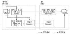
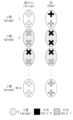
- Figure 27 is a diagram illustrating an example of a conventional quantum conversation protocol in a quantum communication system.
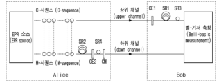
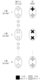
- FIG. 28 is a diagram illustrating an example of a quantum conversation protocol according to one embodiment of the present disclosure in a quantum communication system.
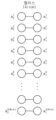
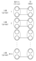
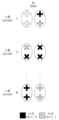
- FIGS. 29 to 33 are conceptual diagrams illustrating a quantum conversation protocol according to one embodiment of the present disclosure.
- FIG. 34 is a flowchart of a quantum conversation method according to one embodiment of the present disclosure.
- FIG. 35 is a flowchart of a quantum conversation method according to another embodiment of the present disclosure.
- each component or feature may be considered optional unless otherwise explicitly stated.
- Each component or feature may be implemented in a form that is not combined with other components or features.
- some components and/or features may be combined to form an embodiment of the present specification.
- the order of operations described in the embodiments of the present specification may be changed. Some components or features of one embodiment may be included in another embodiment, or may be replaced with corresponding components or features of another embodiment.
- the base station is meant as a terminal node of a network that directly communicates with a mobile station.
- a specific operation described as being performed by the base station in this specification may in some cases be performed by an upper node of the base station.
- the 'base station' may be replaced by terms such as a fixed station, a Node B, an eNode B (eNB), a gNode B (gNB), an ng-eNB, an advanced base station (ABS), or an access point.
- eNB eNode B
- gNB gNode B
- ABS advanced base station
- the term terminal may be replaced with terms such as user equipment (UE), mobile station (MS), subscriber station (SS), mobile subscriber station (MSS), mobile terminal, or advanced mobile station (AMS).
- UE user equipment
- MS mobile station
- SS subscriber station
- MSS mobile subscriber station
- AMS advanced mobile station
- the transmitter refers to a fixed and/or mobile node that provides data service or voice service
- the receiver refers to a fixed and/or mobile node that receives data service or voice service.
- a mobile station in the case of uplink, can be a transmitter and a base station can be a receiver.
- a mobile station in the case of downlink, can be a receiver and a base station can be a transmitter.
- Embodiments of the present specification may be supported by standard documents disclosed in at least one of wireless access systems, namely IEEE 802.xx system, 3rd Generation Partnership Project (3GPP) system, 3GPP Long Term Evolution (LTE) system, 3GPP 5G (5th generation) NR (New Radio) system and 3GPP2 system, and in particular, embodiments of the present specification may be supported by 3GPP TS (technical specification) 38.211, 3GPP TS 38.212, 3GPP TS 38.213, 3GPP TS 38.321 and 3GPP TS 38.331 documents.
- 3GPP TS technical specification
- embodiments of the present specification may be applied to other wireless access systems and are not limited to the above-described system.
- they may be applied to systems applied after the 3GPP 5G NR system and are not limited to a specific system.
- CDMA code division multiple access
- FDMA frequency division multiple access
- TDMA time division multiple access
- OFDMA orthogonal frequency division multiple access
- SC-FDMA single carrier frequency division multiple access
- LTE may refer to technology after 3GPP TS 36.xxx Release 8.
- LTE technology after 3GPP TS 36.xxx Release 10 may be referred to as LTE-A
- LTE technology after 3GPP TS 36.xxx Release 13 may be referred to as LTE-A pro.
- 3GPP NR may refer to technology after TS 38.xxx Release 15.
- 3GPP 6G may refer to technology after TS Release 17 and/or Release 18. “xxx” refers to a standard document detail number.
- LTE/NR/6G may be collectively referred to as a 3GPP system.
- FIG. 1 is a diagram illustrating an example of a communication system applied to the present specification.
- a communication system (100) applied to the present specification includes a wireless device, a base station, and a network.
- the wireless device means a device that performs communication using a wireless access technology (e.g., 5G NR, LTE) and may be referred to as a communication/wireless/5G device.
- a wireless access technology e.g., 5G NR, LTE
- the wireless device may include a robot (100a), a vehicle (100b-1, 100b-2), an XR (extended reality) device (100c), a hand-held device (100d), a home appliance (100e), an IoT (Internet of Thing) device (100f), and an AI (artificial intelligence) device/server (100g).
- the vehicle may include a vehicle equipped with a wireless communication function, an autonomous vehicle, a vehicle capable of performing vehicle-to-vehicle communication, etc.
- the vehicles (100b-1, 100b-2) may include unmanned aerial vehicles (UAVs) (e.g., drones).
- UAVs unmanned aerial vehicles
- the XR devices (100c) include augmented reality (AR)/virtual reality (VR)/mixed reality (MR) devices, and may be implemented in the form of a head-mounted device (HMD), a head-up display (HUD) equipped in a vehicle, a television, a smartphone, a computer, a wearable device, a home appliance, digital signage, a vehicle, a robot, etc.
- the portable devices (100d) may include a smartphone, a smart pad, a wearable device (e.g., a smart watch, smart glasses), a computer (e.g., a laptop, etc.), etc.
- the home appliances (100e) may include a TV, a refrigerator, a washing machine, etc.
- the IoT devices (100f) may include sensors, smart meters, etc.
- the base station (120) and network (130) may also be implemented as wireless devices, and a specific wireless device (120a) may act as a base station/network node to other wireless devices.
- Wireless devices (100a to 100f) can be connected to a network (130) via a base station (120).
- AI technology can be applied to the wireless devices (100a to 100f), and the wireless devices (100a to 100f) can be connected to an AI server (100g) via a network (130).
- the network (130) can be configured using a 3G network, a 4G (e.g., LTE) network, a 5G (e.g., NR) network, etc.
- the wireless devices (100a to 100f) can communicate with each other via the base station (120)/network (130), but can also communicate directly (e.g., sidelink communication) without going through the base station (120)/network (130).
- vehicles can communicate directly (e.g., V2V (vehicle to vehicle)/V2X (vehicle to everything) communication).
- an IoT device (100f) (e.g., a sensor) can communicate directly with another IoT device (e.g., a sensor) or another wireless device (100a to 100f).
- Wireless communication/connection can be established between wireless devices (100a to 100f)/base stations (120), and base stations (120)/base stations (120).
- the wireless communication/connection can be established through various wireless access technologies (e.g., 5G NR) such as uplink/downlink communication (150a), sidelink communication (150b) (or, D2D communication), and communication between base stations (150c) (e.g., relay, IAB (integrated access backhaul)).
- 5G NR wireless access technologies
- uplink/downlink communication 150a
- sidelink communication 150b
- D2D communication communication between base stations (150c)
- IAB integrated access backhaul
- the wireless communication/connection can transmit/receive signals through various physical channels.
- various configuration information setting processes for transmitting/receiving wireless signals various signal processing processes (e.g., channel encoding/decoding, modulation/demodulation, resource mapping/demapping, etc.), and resource allocation processes may be performed based on various proposals of this specification.
- FIG. 2 is a drawing illustrating an example of a wireless device to which the present specification can be applied.
- the first wireless device (200a) and the second wireless device (200b) can transmit and receive wireless signals through various wireless access technologies (e.g., LTE, NR).
- ⁇ the first wireless device (200a), the second wireless device (200b) ⁇ can correspond to ⁇ the wireless device (100x), the base station (120) ⁇ and/or ⁇ the wireless device (100x), the wireless device (100x) ⁇ of FIG. 1.
- a first wireless device (200a) includes one or more processors (202a) and one or more memories (204a), and may additionally include one or more transceivers (206a) and/or one or more antennas (208a).
- the processor (202a) controls the memory (204a) and/or the transceiver (206a), and may be configured to implement the descriptions, functions, procedures, suggestions, methods, and/or operational flowcharts disclosed herein.
- the processor (202a) may process information in the memory (204a) to generate first information/signal, and then transmit a wireless signal including the first information/signal via the transceiver (206a).
- the processor (202a) may receive a wireless signal including second information/signal via the transceiver (206a), and then store information obtained from signal processing of the second information/signal in the memory (204a).
- the memory (204a) may be connected to the processor (202a) and may store various information related to the operation of the processor (202a).
- the memory (204a) may perform some or all of the processes controlled by the processor (202a), or may store software codes including instructions for performing the descriptions, functions, procedures, proposals, methods, and/or operational flowcharts disclosed herein.
- the processor (202a) and the memory (204a) may be part of a communication modem/circuit/chip designed to implement wireless communication technology (e.g., LTE, NR).
- the transceiver (206a) may be connected to the processor (202a) and may transmit and/or receive wireless signals via one or more antennas (208a).
- the transceiver (206a) may include a transmitter and/or a receiver.
- the transceiver (206a) may be used interchangeably with an RF (radio frequency) unit.
- wireless device may also mean a communication modem/circuit/chip.
- the second wireless device (200b) includes one or more processors (202b), one or more memories (204b), and may additionally include one or more transceivers (206b) and/or one or more antennas (208b).
- the processor (202b) may control the memory (204b) and/or the transceiver (206b), and may be configured to implement the descriptions, functions, procedures, suggestions, methods, and/or operational flowcharts disclosed herein.
- the processor (202b) may process information in the memory (204b) to generate third information/signal, and then transmit a wireless signal including the third information/signal via the transceiver (206b).
- the processor (202b) may receive a wireless signal including fourth information/signal via the transceiver (206b), and then store information obtained from signal processing of the fourth information/signal in the memory (204b).
- the memory (204b) may be connected to the processor (202b) and may store various information related to the operation of the processor (202b).
- the memory (204b) may perform some or all of the processes controlled by the processor (202b), or may store software codes including instructions for performing the descriptions, functions, procedures, proposals, methods, and/or operational flowcharts disclosed herein.
- the processor (202b) and the memory (204b) may be part of a communication modem/circuit/chip designed to implement wireless communication technology (e.g., LTE, NR).
- the transceiver (206b) may be connected to the processor (202b) and may transmit and/or receive wireless signals via one or more antennas (208b).
- the transceiver (206b) may include a transmitter and/or a receiver.
- the transceiver (206b) may be used interchangeably with an RF unit.
- wireless device may also mean a communication modem/circuit/chip.
- one or more protocol layers may be implemented by one or more processors (202a, 202b).
- one or more processors (202a, 202b) may implement one or more layers (e.g., functional layers such as physical (PHY), media access control (MAC), radio link control (RLC), packet data convergence protocol (PDCP), radio resource control (RRC), service data adaptation protocol (SDAP)).
- layers e.g., functional layers such as physical (PHY), media access control (MAC), radio link control (RLC), packet data convergence protocol (PDCP), radio resource control (RRC), service data adaptation protocol (SDAP)).
- PHY physical
- MAC media access control
- RLC radio link control
- PDCP packet data convergence protocol
- RRC radio resource control
- SDAP service data adaptation protocol
- One or more processors (202a, 202b) may generate one or more Protocol Data Units (PDUs) and/or one or more Service Data Units (SDUs) according to the descriptions, functions, procedures, proposals, methods, and/or operational flowcharts disclosed herein.
- One or more processors (202a, 202b) may generate messages, control information, data or information according to the descriptions, functions, procedures, proposals, methods and/or operational flowcharts disclosed herein.
- One or more processors (202a, 202b) may generate signals (e.g., baseband signals) including PDUs, SDUs, messages, control information, data or information according to the functions, functions, procedures, proposals and/or methods disclosed herein and provide the signals to one or more transceivers (206a, 206b).
- One or more processors (202a, 202b) may receive signals (e.g., baseband signals) from one or more transceivers (206a, 206b) and obtain PDUs, SDUs, messages, control information, data or information according to the descriptions, functions, procedures, proposals, methods and/or operational flowcharts disclosed herein.
- the one or more processors (202a, 202b) may be referred to as a controller, a microcontroller, a microprocessor, or a microcomputer.
- the one or more processors (202a, 202b) may be implemented by hardware, firmware, software, or a combination thereof.
- ASICs application specific integrated circuits
- DSPs digital signal processors
- DSPDs digital signal processing devices
- PLDs programmable logic devices
- FPGAs field programmable gate arrays
- the descriptions, functions, procedures, suggestions, methods, and/or operational flowcharts disclosed herein may be implemented using firmware or software, and the firmware or software may be implemented to include modules, procedures, functions, etc.
- the descriptions, functions, procedures, suggestions, methods and/or operational flowcharts disclosed in this specification may be implemented using firmware or software configured to perform one or more of the processors (202a, 202b), or may be stored in one or more memories (204a, 204b) and executed by one or more of the processors (202a, 202b).
- the descriptions, functions, procedures, suggestions, methods and/or operational flowcharts disclosed in this specification may be implemented using firmware or software in the form of codes, instructions and/or sets of instructions.
- One or more memories (204a, 204b) may be coupled to one or more processors (202a, 202b) and may store various forms of data, signals, messages, information, programs, codes, instructions, and/or commands.
- the one or more memories (204a, 204b) may be comprised of read only memory (ROM), random access memory (RAM), erasable programmable read only memory (EPROM), flash memory, hard drives, registers, cache memory, computer readable storage media, and/or combinations thereof.
- the one or more memories (204a, 204b) may be located internally and/or externally to the one or more processors (202a, 202b). Additionally, the one or more memories (204a, 204b) may be coupled to the one or more processors (202a, 202b) via various technologies, such as wired or wireless connections.
- One or more transceivers (206a, 206b) can transmit user data, control information, wireless signals/channels, etc., as described in the methods and/or flowcharts of this specification, to one or more other devices.
- One or more transceivers (206a, 206b) can receive user data, control information, wireless signals/channels, etc., as described in the descriptions, functions, procedures, suggestions, methods and/or flowcharts of this specification, from one or more other devices.
- one or more transceivers (206a, 206b) can be coupled to one or more processors (202a, 202b) and can transmit and receive wireless signals.
- one or more processors (202a, 202b) can control one or more transceivers (206a, 206b) to transmit user data, control information, or wireless signals to one or more other devices. Additionally, one or more processors (202a, 202b) may control one or more transceivers (206a, 206b) to receive user data, control information, or wireless signals from one or more other devices.
- one or more transceivers (206a, 206b) may be coupled to one or more antennas (208a, 208b), and one or more transceivers (206a, 206b) may be configured to transmit and receive user data, control information, wireless signals/channels, and the like, as referred to in the descriptions, functions, procedures, suggestions, methods, and/or operational flowcharts disclosed herein, via one or more antennas (208a, 208b).
- one or more antennas may be multiple physical antennas or multiple logical antennas (e.g., antenna ports).
- One or more transceivers (206a, 206b) may convert received user data, control information, wireless signals/channels, etc.
- One or more transceivers (206a, 206b) may convert processed user data, control information, wireless signals/channels, etc. from baseband signals to RF band signals using one or more processors (202a, 202b).
- one or more transceivers (206a, 206b) may include an (analog) oscillator and/or filter.
- FIG. 3 is a diagram illustrating a method for processing a transmission signal applied to the present specification.
- the transmission signal may be processed by a signal processing circuit.
- the signal processing circuit (300) may include a scrambler (310), a modulator (320), a layer mapper (330), a precoder (340), a resource mapper (350), and a signal generator (360).
- the operation/function of FIG. 3 may be performed in the processor (202a, 202b) and/or the transceiver (206a, 206b) of FIG. 2.
- blocks 310 to 350 may be implemented in the processor (202a, 202b) of FIG. 2
- block 360 may be implemented in the transceiver (206a, 206b) of FIG. 2, and are not limited to the above-described embodiments.
- the codeword can be converted into a wireless signal through the signal processing circuit (300) of FIG. 3.
- the codeword is an encoded bit sequence of an information block.
- the information block can include a transport block (e.g., a UL-SCH transport block, a DL-SCH transport block).
- the wireless signal can be transmitted through various physical channels (e.g., a PUSCH, a PDSCH) of FIG. 6.
- the codeword can be converted into a bit sequence scrambled by a scrambler (310).
- the scramble sequence used for scrambling is generated based on an initialization value, and the initialization value can include ID information of a wireless device, etc.
- the scrambled bit sequence can be modulated into a modulation symbol sequence by a modulator (320).
- the modulation scheme can include pi/2-BPSK (pi/2-binary phase shift keying), m-PSK (m-phase shift keying), m-QAM (m-quadrature amplitude modulation), etc.
- the complex modulation symbol sequence can be mapped to one or more transmission layers by the layer mapper (330).
- the modulation symbols of each transmission layer can be mapped to the corresponding antenna port(s) by the precoder (340) (precoding).
- the output z of the precoder (340) can be obtained by multiplying the output y of the layer mapper (330) by a precoding matrix W of N*M.
- N is the number of antenna ports
- M is the number of transmission layers.
- the precoder (340) can perform precoding after performing transform precoding (e.g., DFT (discrete Fourier transform) transform) on the complex modulation symbols.
- the precoder (340) can perform precoding without performing transform precoding.
- the resource mapper (350) can map modulation symbols of each antenna port to time-frequency resources.
- the time-frequency resources can include a plurality of symbols (e.g., CP-OFDMA symbols, DFT-s-OFDMA symbols) in the time domain and a plurality of subcarriers in the frequency domain.
- the signal generator (360) generates a wireless signal from the mapped modulation symbols, and the generated wireless signal can be transmitted to another device through each antenna.
- the signal generator (360) can include an inverse fast fourier transform (IFFT) module, a cyclic prefix (CP) inserter, a digital-to-analog converter (DAC), a frequency uplink converter, etc.
- IFFT inverse fast fourier transform
- CP cyclic prefix
- DAC digital-to-analog converter
- the signal processing process for receiving signals in a wireless device can be configured in reverse order of the signal processing process (310 to 360) of FIG. 3.
- a wireless device e.g., 200a and 200b of FIG. 2
- the received wireless signal can be converted into a baseband signal through a signal restorer.
- the signal restorer can include a frequency downlink converter, an analog-to-digital converter (ADC), a CP remover, and a fast Fourier transform (FFT) module.
- ADC analog-to-digital converter
- FFT fast Fourier transform
- the baseband signal can be restored to a codeword through a resource demapper process, a postcoding process, a demodulation process, and a descramble process.
- a signal processing circuit for a received signal may include a signal restorer, a resource de-mapper, a postcoder, a demodulator, a de-scrambler and a decoder.
- FIG. 4 is a drawing illustrating another example of a wireless device to which the present specification applies.
- the wireless device (400) corresponds to the wireless device (200a, 200b) of FIG. 2, and may be composed of various elements, components, units/units, and/or modules.
- the wireless device (400) may include a communication unit (410), a control unit (420), a memory unit (430), and additional elements (440).
- the communication unit may include a communication circuit (412) and a transceiver(s) (414).
- the communication circuit (412) may include one or more processors (202a, 202b) and/or one or more memories (204a, 204b) of FIG. 2.
- the transceiver(s) (414) may include one or more transceivers (206a, 206b) and/or one or more antennas (208a, 208b) of FIG. 2.
- the control unit (420) is electrically connected to the communication unit (410), the memory unit (430), and the additional elements (440) and controls overall operations of the wireless device.
- the control unit (420) may control electrical/mechanical operations of the wireless device based on programs/codes/commands/information stored in the memory unit (430).
- control unit (420) may transmit information stored in the memory unit (430) to an external device (e.g., another communication device) via a wireless/wired interface through the communication unit (410), or store information received from an external device (e.g., another communication device) via a wireless/wired interface in the memory unit (430).
- an external device e.g., another communication device
- store information received from an external device e.g., another communication device
- the additional element (440) may be configured in various ways depending on the type of the wireless device.
- the additional element (440) may include at least one of a power unit/battery, an input/output unit, a driving unit, and a computing unit.
- the wireless device (400) may be implemented in the form of a robot (FIG. 1, 100a), a vehicle (FIG. 1, 100b-1, 100b-2), an XR device (FIG. 1, 100c), a portable device (FIG. 1, 100d), a home appliance (FIG. 1, 100e), an IoT device (FIG.
- Wireless devices may be mobile or stationary, depending on the use/service.
- various elements, components, units/parts, and/or modules within the wireless device (400) may be entirely interconnected via a wired interface, or at least some may be wirelessly connected via a communication unit (410).
- the control unit (420) and the communication unit (410) may be wired, and the control unit (420) and the first unit (e.g., 430, 440) may be wirelessly connected via the communication unit (410).
- each element, component, unit/part, and/or module within the wireless device (400) may further include one or more elements.
- the control unit (420) may be composed of one or more processor sets.
- control unit (420) may be composed of a set of a communication control processor, an application processor, an electronic control unit (ECU), a graphics processing processor, a memory control processor, etc.
- memory unit (430) may be composed of RAM, DRAM (dynamic RAM), ROM, flash memory, volatile memory, non-volatile memory, and/or a combination thereof.
- FIG. 5 is a drawing illustrating an example of a portable device to which the present specification applies.
- FIG. 5 illustrates an example of a mobile device to which the present specification applies.
- the mobile device may include a smart phone, a smart pad, a wearable device (e.g., a smart watch, a smart glass), a portable computer (e.g., a laptop, etc.).
- the mobile device may be referred to as a mobile station (MS), a user terminal (UT), a mobile subscriber station (MSS), a subscriber station (SS), an advanced mobile station (AMS), or a wireless terminal (WT).
- MS mobile station
- UT user terminal
- MSS mobile subscriber station
- SS subscriber station
- AMS advanced mobile station
- WT wireless terminal
- the portable device (500) may include an antenna unit (508), a communication unit (510), a control unit (520), a memory unit (530), a power supply unit (540a), an interface unit (540b), and an input/output unit (540c).
- the antenna unit (508) may be configured as a part of the communication unit (510). Blocks 510 to 530/540a to 540c correspond to blocks 410 to 430/440 of FIG. 4, respectively.
- the communication unit (510) can transmit and receive signals (e.g., data, control signals, etc.) with other wireless devices and base stations.
- the control unit (520) can control components of the portable device (500) to perform various operations.
- the control unit (520) can include an AP (application processor).
- the memory unit (530) can store data/parameters/programs/codes/commands required for operating the portable device (500).
- the memory unit (530) can store input/output data/information, etc.
- the power supply unit (540a) supplies power to the portable device (500) and can include a wired/wireless charging circuit, a battery, etc.
- the interface unit (540b) can support connection between the portable device (500) and other external devices.
- the interface unit (540b) can include various ports (e.g., audio input/output ports, video input/output ports) for connection with external devices.
- the input/output unit (540c) can input or output image information/signals, audio information/signals, data, and/or information input from a user.
- the input/output unit (540c) can include a camera, a microphone, a user input unit, a display unit (540d), a speaker, and/or a haptic module.
- the input/output unit (540c) obtains information/signals (e.g., touch, text, voice, image, video) input by the user, and the obtained information/signals can be stored in the memory unit (530).
- the communication unit (510) converts the information/signals stored in the memory into wireless signals, and can directly transmit the converted wireless signals to other wireless devices or to a base station.
- the communication unit (510) can receive wireless signals from other wireless devices or base stations, and then restore the received wireless signals to the original information/signals.
- the restored information/signals can be stored in the memory unit (530) and then output in various forms (e.g., text, voice, image, video, haptic) through the input/output unit (540c).
- a terminal can receive information from a base station through the downlink (DL) and transmit information to the base station through the uplink (UL).
- the information transmitted and received by the base station and the terminal includes general data information and various control information, and various physical channels exist depending on the type/purpose of the information they transmit and receive.
- FIG. 6 is a diagram illustrating physical channels applicable to this specification and a signal transmission method using them.
- a terminal When a terminal is powered on again from a powered-off state or enters a new cell, it performs an initial cell search task such as synchronizing with the base station at step S611. To do this, the terminal can receive a primary synchronization channel (P-SCH) and a secondary synchronization channel (S-SCH) from the base station to synchronize with the base station and obtain information such as a cell ID.
- P-SCH primary synchronization channel
- S-SCH secondary synchronization channel
- the terminal can receive a physical broadcast channel (PBCH) signal from the base station to obtain broadcast information within the cell. Meanwhile, the terminal can receive a downlink reference signal (DL RS: Downlink Reference Signal) in the initial cell search phase to check the downlink channel status. After completing the initial cell search, the terminal can receive a physical downlink control channel (PDCCH) and a physical downlink shared channel (PDSCH) according to the physical downlink control channel information in step S612 to obtain more specific system information.
- PBCH physical broadcast channel
- DL RS Downlink Reference Signal
- the terminal may perform a random access procedure such as steps S613 to S616 to complete connection to the base station.
- the terminal may transmit a preamble through a physical random access channel (PRACH) (S613), and receive a random access response (RAR) for the preamble through a physical downlink control channel and a physical downlink shared channel corresponding thereto (S614).
- the terminal may transmit a physical uplink shared channel (PUSCH) using scheduling information in the RAR (S615), and perform a contention resolution procedure such as receiving a physical downlink control channel signal and a physical downlink shared channel signal corresponding thereto (S616).
- a terminal that has performed the procedure described above can then perform reception of a physical downlink control channel signal and/or a physical downlink shared channel signal (S617) and transmission of a physical uplink shared channel (PUSCH) signal and/or a physical uplink control channel (PUCCH) signal (S618) as a general uplink/downlink signal transmission procedure.
- a physical downlink control channel signal and/or a physical downlink shared channel signal S617
- transmission of a physical uplink shared channel (PUSCH) signal and/or a physical uplink control channel (PUCCH) signal S618) as a general uplink/downlink signal transmission procedure.
- PUSCH physical uplink shared channel
- PUCCH physical uplink control channel
- UCI uplink control information
- UCI includes hybrid automatic repeat and request acknowledgement/negative-ACK (HARQ-ACK/NACK), scheduling request (SR), channel quality indication (CQI), precoding matrix indication (PMI), rank indication (RI), beam indication (BI) information, etc.
- HARQ-ACK/NACK hybrid automatic repeat and request acknowledgement/negative-ACK
- SR scheduling request
- CQI channel quality indication
- PMI precoding matrix indication
- RI rank indication
- BI beam indication
- UCI is generally transmitted periodically through PUCCH, but depending on the embodiment (e.g., when control information and traffic data must be transmitted simultaneously), it may be transmitted through PUSCH.
- the terminal may aperiodically transmit UCI through PUSCH upon request/instruction from the network.
- Figure 7 is a diagram illustrating the structure of a wireless frame applicable to this specification.
- Uplink and downlink transmission based on the NR system can be based on frames such as those in FIG. 7.
- one radio frame has a length of 10 ms and can be defined by two 5 ms half-frames (half-frames, HF).
- One half-frame can be defined by five 1 ms subframes (subframes, SF).
- One subframe is divided into one or more slots, and the number of slots in a subframe can depend on subcarrier spacing (SCS).
- SCS subcarrier spacing
- each slot can include 12 or 14 OFDM (A) symbols depending on CP (cyclic prefix).
- CP cyclic prefix
- each slot can include 14 symbols.
- each slot can include 12 symbols.
- the symbol may include an OFDM symbol (or CP-OFDM symbol), an SC-FDMA symbol (or DFT-s-OFDM symbol).
- Table 1 shows the number of symbols per slot, the number of slots per frame, and the number of slots per subframe according to SCS when a general CP is used
- Table 2 shows the number of symbols per slot, the number of slots per frame, and the number of slots per subframe according to SCS when an extended CP is used.
- N slot symb may represent the number of symbols in a slot
- N frame, ⁇ slot may represent the number of slots in a frame
- N subframe, ⁇ slot may represent the number of slots in a subframe
- OFDM(A) numerologies e.g., SCS, CP length, etc.
- OFDM(A) numerologies may be set differently between multiple cells that are merged into one terminal.
- the (absolute time) section of a time resource e.g., SF, slot or TTI
- TU time unit
- NR can support multiple numerologies (or subcarrier spacing (SCS)) to support various 5G services. For example, when the SCS is 15 kHz, it supports wide area in traditional cellular bands, when the SCS is 30 kHz/60 kHz, it supports dense-urban, lower latency and wider carrier bandwidth, and when the SCS is 60 kHz or higher, it can support bandwidths larger than 24.25 GHz to overcome phase noise.
- SCS subcarrier spacing
- the NR frequency band is defined by two types of frequency ranges (FR1, FR2).
- FR1 and FR2 can be configured as shown in the table below.
- FR2 can mean millimeter wave (mmW).
- the numerology described above may be set differently in a communication system to which the present specification is applicable.
- a Terahertz wave (THz) band may be used as a frequency band higher than the FR2 described above.
- the SCS may be set larger than in the NR system, and the number of slots may also be set differently, and is not limited to the above-described embodiment.
- the THz band will be described later.
- Figure 8 is a drawing illustrating a slot structure applicable to this specification.
- a slot contains multiple symbols in the time domain. For example, in the case of a normal CP, a slot contains 7 symbols, but in the case of an extended CP, a slot may contain 6 symbols.
- a carrier contains multiple subcarriers in the frequency domain.
- An RB (Resource Block) can be defined as multiple (e.g., 12) consecutive subcarriers in the frequency domain.
- a Bandwidth Part is defined as multiple consecutive (P)RBs in the frequency domain and can correspond to one numerology (e.g., SCS, CP length, etc.).
- a carrier can contain up to N (e.g., 5) BWPs. Data communication is performed through activated BWPs, and only one BWP can be activated for one terminal.
- N e.g., 5
- Each element in the resource grid is referred to as a resource element (RE), and one complex symbol can be mapped.
- RE resource element
- the 6G (wireless communication) system aims at (i) very high data rates per device, (ii) a very large number of connected devices, (iii) global connectivity, (iv) very low latency, (v) lower energy consumption of battery-free IoT devices, (vi) ultra-reliable connectivity, and (vii) connected intelligence with machine learning capabilities.
- the vision of the 6G system can be divided into four aspects: "intelligent connectivity”, “deep connectivity”, “holographic connectivity”, and "ubiquitous connectivity", and the 6G system can satisfy the requirements as shown in Table 4 below. That is, Table 4 is a table showing the requirements of the 6G system.
- 6G systems may have key factors such as enhanced mobile broadband (eMBB), ultra-reliable low latency communications (URLLC), massive machine type communications (mMTC), AI integrated communication, tactile internet, high throughput, high network capacity, high energy efficiency, low backhaul and access network congestion, and enhanced data security.
- eMBB enhanced mobile broadband
- URLLC ultra-reliable low latency communications
- mMTC massive machine type communications
- AI integrated communication tactile internet, high throughput, high network capacity, high energy efficiency, low backhaul and access network congestion, and enhanced data security.
- FIG. 9 is a diagram illustrating an example of a communication structure that can be provided in a 6G system applicable to this specification.
- the 6G system is expected to have 50 times higher simultaneous wireless communication connectivity than the 5G wireless communication system.
- URLLC a key feature of 5G, is expected to become a more important technology in 6G communication by providing end-to-end delay of less than 1 ms.
- the 6G system will have much better volumetric spectral efficiency than the frequently used area spectral efficiency.
- the 6G system can provide very long battery life and advanced battery technology for energy harvesting, so that mobile devices in the 6G system may not need to be charged separately.
- new network characteristics in 6G may be as follows.
- AI can be applied at each stage of the communication process (or at each stage of signal processing, as described below).
- 6G wireless networks will transfer power to charge the batteries of devices such as smartphones and sensors. Therefore, wireless information and energy transfer (WIET) will be integrated.
- WIET wireless information and energy transfer
- Small cell networks The idea of small cell networks was introduced to improve the quality of received signals as a result of increased throughput, energy efficiency, and spectrum efficiency in cellular systems. As a result, small cell networks are an essential feature for 5G and beyond 5G (5GB) communication systems. Accordingly, 6G communication systems also adopt the characteristics of small cell networks.
- Ultra-dense heterogeneous networks will be another important feature of 6G communication systems.
- a multi-tier network composed of heterogeneous networks improves overall QoS and reduces costs.
- Backhaul connections are characterized by high-capacity backhaul networks to support high-capacity traffic.
- High-speed fiber optics and free-space optics (FSO) systems may be possible solutions to this problem.
- High-precision localization (or location-based services) through communication is one of the functions of 6G wireless communication systems. Therefore, radar systems will be integrated with 6G networks.
- Softwarization and virtualization are two important features that are fundamental to the design process in 5GB networks to ensure flexibility, reconfigurability, and programmability. In addition, billions of devices can be shared on a shared physical infrastructure.
- the most important and newly introduced technology in the 6G system is AI.
- the 4G system did not involve AI.
- the 5G system will support partial or very limited AI.
- the 6G system will be fully AI-supported for automation.
- Advances in machine learning will create more intelligent networks for real-time communications in 6G.
- Introducing AI in communications can simplify and improve real-time data transmission.
- AI can use numerous analyses to determine how complex target tasks are performed. In other words, AI can increase efficiency and reduce processing delays.
- AI-based physical layer transmission means applying signal processing and communication mechanisms based on AI drivers rather than traditional communication frameworks in terms of fundamental signal processing and communication mechanisms. For example, it can include deep learning-based channel coding and decoding, deep learning-based signal estimation and detection, deep learning-based multiple input multiple output (MIMO) mechanisms, and AI-based resource scheduling and allocation.
- MIMO multiple input multiple output
- Deep learning-based AI algorithms require a large amount of training data to optimize training parameters.
- a large amount of training data is used offline. This is because static training on training data in a specific channel environment can cause a conflict between the dynamic characteristics and diversity of the wireless channel.
- Machine learning refers to a series of operations that teach machines to create machines that can perform tasks that people can or cannot do.
- Machine learning requires data and a learning model.
- data learning methods can be broadly divided into three: supervised learning, unsupervised learning, and reinforcement learning.
- the learning method may vary. For example, if the goal is to accurately predict data transmitted from the transmitter to the receiver in a communication system, it is preferable to perform learning using supervised learning rather than unsupervised learning or reinforcement learning.
- the neural network cores used in learning methods can be broadly divided into deep neural networks (DNN), convolutional deep neural networks (CNN), and recurrent Boltzmann machines (RNN), and these learning models can be applied.
- DNN deep neural networks
- CNN convolutional deep neural networks
- RNN recurrent Boltzmann machines
- An artificial neural network is an example of multiple perceptrons connected together.
- a large artificial neural network structure can extend the simplified perceptron structure illustrated in Fig. 10 to apply the input vector to perceptrons of different dimensions. For convenience of explanation, input values or output values are called nodes.
- the layer where the input vector is located is called the input layer
- the layer where the final output value is located is called the output layer
- all layers located between the input layer and the output layer are called hidden layers.
- the example in Fig. 4 shows three layers, but when counting the number of actual artificial neural network layers, the input layer is excluded, so it can be viewed as a total of two layers.
- the artificial neural network is composed of perceptrons of basic blocks connected in two dimensions.
- the above-mentioned input layer, hidden layer, and output layer can be applied jointly not only to multilayer perceptron but also to various artificial neural network structures such as CNN and RNN, which will be described later.
- CNN neural network
- RNN deep neural network
- the deep neural network illustrated in Fig. 12 is a multilayer perceptron composed of eight hidden layers and eight output layers.
- the multilayer perceptron structure is expressed as a fully-connected neural network.
- a fully-connected neural network there is no connection relationship between nodes located in the same layer, and there is a connection relationship only between nodes located in adjacent layers.
- DNN has a fully-connected neural network structure and is composed of a combination of multiple hidden layers and activation functions, and can be usefully applied to identify correlation characteristics between inputs and outputs.
- the correlation characteristic can mean the joint probability of inputs and outputs.
- Fig. 13 can assume a case where nodes are arranged two-dimensionally, with w nodes in width and h nodes in height (convolutional neural network structure of Fig. 6).
- a weight is added to each connection in the connection process from one input node to the hidden layer, a total of h ⁇ w weights must be considered. Since there are h ⁇ w nodes in the input layer, a total of h2w2 weights are required between two adjacent layers.
- the convolutional neural network of Fig. 13 has a problem in that the number of weights increases exponentially according to the number of connections. Therefore, instead of considering the connections of all modes between adjacent layers, it assumes that there is a small filter, and performs weighted sum and activation function operations on the overlapping portions of the filters, as in Fig. 7.
- One filter has a weight corresponding to the number of its size, and learning of the weight can be performed so that a specific feature on the image can be extracted as a factor and output.
- a 3 ⁇ 3 sized filter is applied to the 3 ⁇ 3 area at the upper left of the input layer, and the output value resulting from performing weighted sum and activation function operations for the corresponding node is stored in z22.
- the above filter performs weighted sum and activation function operations while moving horizontally and vertically at a certain interval while scanning the input layer, and places the output value at the current filter position.
- This operation method is similar to the convolution operation for images in the field of computer vision, so a deep neural network with this structure is called a convolutional neural network (CNN), and the hidden layer generated as a result of the convolution operation is called a convolutional layer.
- a neural network with multiple convolutional layers is called a deep convolutional neural network (DCNN).
- the number of weights can be reduced by calculating the weighted sum by including only the nodes located in the area covered by the filter at the node where the current filter is located.
- one filter can be used to focus on features for a local area.
- CNN can be effectively applied to image data processing where physical distance in a two-dimensional area is an important judgment criterion. Meanwhile, CNN can apply multiple filters immediately before the convolution layer, and can also generate multiple output results through the convolution operation of each filter.
- a recurrent neural network structure the structure that applies the method of inputting one element of the data sequence at each time step and inputting the output vector (hidden vector) of the hidden layer output at a specific time together with the next element in the sequence to an artificial neural network is called a recurrent neural network structure.
- a recurrent neural network is a structure that inputs elements (x1(t), x2(t), ,..., xd(t)) of a certain time point t in a data sequence into a fully connected neural network, and applies a weighted sum and an activation function along with the hidden vector (z1(t-1), z2(t-1),..., zH(t-1)) of the immediately previous time point t-1.
- the reason for transmitting the hidden vector to the next time point in this way is because the information in the input vectors of the previous time points is considered to be accumulated in the hidden vector of the current time point.
- Figure 16 shows an example of the operational structure of a recurrent neural network.
- the recurrent neural network operates in a predetermined time order on the input data sequence.
- Recurrent neural networks are designed to be usefully applied to sequence data (e.g. natural language processing).
- various deep learning techniques such as DNN, CNN, RNN, Restricted Boltzmann Machine (RBM), Deep Belief Network (DBN), and Deep Q-Network, and can be applied to fields such as computer vision, speech recognition, natural language processing, and speech/signal processing.
- AI-based physical layer transmission means applying signal processing and communication mechanisms based on AI drivers, rather than traditional communication frameworks, in terms of fundamental signal processing and communication mechanisms. For example, it can include deep learning-based channel coding and decoding, deep learning-based signal estimation and detection, deep learning-based MIMO mechanism, and AI-based resource scheduling and allocation.
- THz communication can be applied in 6G systems.
- the data transmission rate can be increased by increasing the bandwidth. This can be done by using sub-THz communication with a wide bandwidth and applying advanced massive MIMO technology.
- FIG. 17 is a diagram illustrating an electromagnetic spectrum applicable to the present specification.
- THz waves also known as sub-millimeter radiation, generally represent a frequency band between 0.1 THz and 10 THz with a corresponding wavelength in the range of 0.03 mm-3 mm.
- the 100 GHz-300 GHz band range (Sub THz band) is considered to be a major part of the THz band for cellular communications. Adding the Sub-THz band to the mmWave band will increase the capacity of 6G cellular communications.
- 300 GHz-3 THz is in the far infrared (IR) frequency band.
- the 300 GHz-3 THz band is a part of the optical band, but is at the boundary of the optical band, just behind the RF band. Therefore, this 300 GHz-3 THz band exhibits similarities with RF.
- THz communications Key characteristics include (i) widely available bandwidth to support very high data rates, and (ii) high path loss at high frequencies (highly directional antennas are essential).
- the narrow beam widths generated by highly directional antennas reduce interference.
- the small wavelength of THz signals allows a much larger number of antenna elements to be integrated into devices and BSs operating in this band. This allows the use of advanced adaptive array techniques to overcome range limitations.
- OWC optical wireless communication
- OWC technology is planned for 6G communication in addition to RF-based communication for all possible device-to-access networks. These networks connect to network-to-backhaul/fronthaul network connections.
- OWC technology has already been used since 4G communication systems, but it will be used more widely to meet the needs of 6G communication systems.
- OWC technologies such as light fidelity, visible light communication, optical camera communication, and free space optical (FSO) communication based on optical bands are already well known technologies.
- Optical wireless technology-based communication can provide very high data rates, low latency, and secure communication.
- LiDAR light detection and ranging
- FSO can be a good technology to provide backhaul connections in 6G systems together with optical fiber networks.
- FSO supports large-capacity backhaul connections for remote and non-remote areas such as the ocean, space, underwater, and isolated islands.
- FSO also supports cellular base station connections.
- MIMO technology One of the key technologies to improve spectral efficiency is the application of MIMO technology. As MIMO technology improves, spectral efficiency also improves. Therefore, massive MIMO technology will be important in 6G systems. Since MIMO technology utilizes multiple paths, multiplexing technology and beam generation and operation technology suitable for the THz band must also be considered so that data signals can be transmitted through more than one path.
- Blockchain will be an important technology for managing large amounts of data in future communication systems.
- Blockchain is a form of distributed ledger technology, where a distributed ledger is a database distributed across a large number of nodes or computing devices. Each node replicates and stores an identical copy of the ledger.
- Blockchain is managed by a peer-to-peer (P2P) network. It can exist without being managed by a central authority or server. Data in a blockchain is collected together and organized into blocks. Blocks are linked together and protected using cryptography.
- Blockchain perfectly complements large-scale IoT with its inherently enhanced interoperability, security, privacy, reliability, and scalability.
- blockchain technology offers several features such as interoperability between devices, traceability of large amounts of data, autonomous interaction of other IoT systems, and large-scale connection stability of 6G communication systems.
- 3D BS will be provided via low-orbit satellites and UAVs. Adding a new dimension in terms of altitude and associated degrees of freedom makes 3D connections significantly different from existing 2D networks.
- Unmanned aerial vehicles or drones will be a key element in 6G wireless communications.
- high-speed data wireless connectivity is provided using UAV technology.
- Base station entities are installed on UAVs to provide cellular connectivity.
- UAVs have certain features that are not found in fixed base station infrastructure such as easy deployment, robust line-of-sight links, and freedom of movement with controlled mobility.
- emergency situations such as natural disasters, deployment of terrestrial communication infrastructure is not economically feasible and sometimes cannot provide services in volatile environments.
- UAVs can easily handle such situations.
- UAVs will be a new paradigm in wireless communications. This technology facilitates three basic requirements of wireless networks namely eMBB, URLLC, and mMTC.
- UAVs can also support several purposes such as enhancing network connectivity, fire detection, disaster emergency services, security and surveillance, pollution monitoring, parking monitoring, and accident monitoring. Therefore, UAV technology is recognized as one of the most important technologies for 6G communications.
- Tight integration of multiple frequencies and heterogeneous communication technologies is crucial in 6G systems.
- users can seamlessly move from one network to another without having to make any manual configuration on their devices.
- the best network among the available communication technologies will be automatically selected. This will break the limitations of the cell concept in wireless communications.
- user movement from one cell to another causes too many handovers in dense networks, resulting in handover failures, handover delays, data loss, and ping-pong effects.
- 6G cell-free communications will overcome all these and provide better QoS. Cell-free communications will be achieved through multi-connectivity and multi-tier hybrid technologies and different heterogeneous radios in the devices.
- WIET Integrated wireless information and energy transfer
- WIET uses the same fields and waves as wireless communication systems. In particular, sensors and smartphones will be charged using wireless power transfer during communication. WIET is a promising technology for extending the life of battery-powered wireless systems. Therefore, battery-less devices will be supported in 6G communications.
- Autonomous wireless networks are capable of continuously sensing dynamically changing environmental conditions and exchanging information between different nodes.
- sensing will be tightly integrated with communications to support autonomous systems.
- each access network will be connected to backhaul connections such as fiber and FSO networks. To cope with the very large number of access networks, there will be tight integration between access and backhaul networks.
- Beamforming is a signal processing procedure that adjusts an array of antennas to transmit a wireless signal in a specific direction. It is a subset of smart antennas or advanced antenna systems. Beamforming technology has several advantages such as high signal-to-noise ratio, interference avoidance and rejection, and high network efficiency.
- Hologram beamforming (HBF) is a new beamforming method that is quite different from MIMO systems because it uses software-defined antennas. HBF will be a very effective approach for efficient and flexible transmission and reception of signals in multi-antenna communication devices in 6G.
- Big data analytics is a complex process for analyzing a variety of large data sets or big data. This process ensures complete data management by finding information such as hidden data, unknown correlations, and customer tendencies. Big data is collected from various sources such as video, social networks, images, and sensors. This technology is widely used to process massive data in 6G systems.
- LIS large intelligent surface
- LIS is an artificial surface made of electromagnetic materials and can change the propagation of incoming and outgoing radio waves.
- LIS can be seen as an extension of massive MIMO, but it has different array structures and operating mechanisms from massive MIMO.
- LIS has the advantage of low power consumption because it operates as a reconfigurable reflector with passive elements, that is, it passively reflects signals without using an active RF chain.
- each passive reflector of LIS must independently adjust the phase shift of the incident signal, it can be advantageous for wireless communication channels. By appropriately adjusting the phase shift via the LIS controller, the reflected signal can be collected at the target receiver to boost the received signal power.
- THz Terahertz
- FIG. 18 is a diagram illustrating a THz communication method applicable to this specification.
- THz waves are located between the RF (Radio Frequency)/millimeter (mm) and infrared bands, and (i) compared to visible light/infrared rays, they penetrate non-metallic/non-polarizable materials well, and compared to RF/millimeter waves, they have a shorter wavelength, so they have high straightness and can enable beam focusing.
- the frequency band expected to be used for THz wireless communication may be the D-band (110 GHz to 170 GHz) or H-band (220 GHz to 325 GHz) bands where propagation loss due to absorption of molecules in the air is small.
- standardization discussions for THz wireless communication are being centered around the IEEE 802.15 THz WG (working group), and standard documents issued by the TG (task group) of IEEE 802.15 (e.g., TG3d, TG3e) can specify or supplement the contents described in this specification.
- THz wireless communication can be applied to wireless cognition, sensing, imaging, wireless communication, THz navigation, etc.
- THz wireless communication scenarios can be classified into a macro network, a micro network, and a nanoscale network.
- THz wireless communication can be applied to vehicle-to-vehicle (V2V) connections and backhaul/fronthaul connections.
- V2V vehicle-to-vehicle
- THz wireless communication can be applied to fixed point-to-point or multi-point connections such as indoor small cells, wireless connections in data centers, and near-field communications such as kiosk downloading.
- Table 5 below is a table showing examples of technologies that can be used in THz waves.
- FIG. 19 is a diagram illustrating a THz wireless communication transceiver applicable to the present specification.
- THz wireless communication can be classified based on the method for THz generation and reception.
- THz generation methods can be classified into optical device or electronic device-based technologies.
- the multiplier is a circuit that has an output frequency that is N times that of the input, and matches it to a desired harmonic frequency and filters out all remaining frequencies.
- beamforming can be implemented by applying an array antenna, etc. to the antenna of Fig. 19.
- IF represents intermediate frequency
- tripler and multipler represent multipliers
- PA represents a power amplifier
- LNA represents a low noise amplifier
- PLL represents a phase-locked loop.
- FIG. 20 is a diagram illustrating a THz signal generation method applicable to the present specification.
- FIG. 21 is a diagram illustrating a wireless communication transceiver applicable to the present specification.
- the optical device-based THz wireless communication technology refers to a method of generating and modulating a THz signal using an optical device.
- the optical device-based THz signal generation technology is a technology that generates an ultra-high-speed optical signal using a laser and an optical modulator, and converts it into a THz signal using an ultra-high-speed optical detector. Compared to a technology that uses only electronic devices, this technology makes it easy to increase the frequency, enables high-power signal generation, and obtains flat response characteristics in a wide frequency band.
- a laser diode, a wideband optical modulator, and an ultra-high-speed optical detector are required, as illustrated in FIG. 20.
- an optical coupler refers to a semiconductor device that transmits an electrical signal using optical waves to provide electrical isolation and coupling between circuits or systems
- a uni-travelling carrier photo-detector (UTC-PD) is one of the photodetectors, which uses electrons as active carriers and is a device that reduces the travel time of electrons by bandgap grading.
- UTC-PD is capable of detecting light at 150 GHz or higher.
- EDFA erbium-doped fiber amplifier
- PD photo detector
- OSA optical sub assembly that modularizes various optical communication functions (e.g., photoelectric conversion, electro-optical conversion, etc.) into a single component
- DSO digital storage oscilloscope
- Fig. 22 is a drawing illustrating a transmitter structure applicable to the present specification.
- Fig. 23 is a drawing illustrating a modulator structure applicable to the present specification.
- a general optical source of a laser can be passed through an optical wave guide to change the phase of a signal, etc.
- data is loaded by changing the electrical characteristics through a microwave contact, etc. Therefore, the optical modulator output is formed as a modulated waveform.
- An optical/electrical modulator (O/E converter) can generate a THz pulse according to an optical rectification operation by a nonlinear crystal, an optical/electrical conversion by a photoconductive antenna, an emission from a bunch of relativistic electrons, etc.
- a terahertz pulse (THz pulse) generated in the above manner can have a length in the unit of femto second to pico second.
- An optical/electronic converter (O/E converter) performs down conversion by utilizing the non-linearity of the device.
- the available bandwidth can be classified based on an oxygen attenuation of 10 ⁇ 2 dB/km in the spectrum up to 1 THz. Accordingly, a framework may be considered in which the available bandwidth is composed of multiple band chunks. As an example of the framework, if the length of a THz pulse for one carrier is set to 50 ps, the bandwidth (BW) becomes approximately 20 GHz.
- Effective down conversion from the infrared band to the terahertz band (THz band) depends on how to utilize the nonlinearity of the optical/electrical converter (O/E converter). That is, in order to down convert to a desired terahertz band (THz band), it is required to design an optical/electrical converter (O/E converter) that has the most ideal nonlinearity for moving to the terahertz band (THz band). If an optical/electrical converter (O/E converter) that does not match the target frequency band is used, there is a high possibility that errors will occur in the amplitude and phase of the pulse.
- a terahertz transmit/receive system can be implemented using one optical-to-electrical converter.
- the number of optical-to-electrical converters may be required as many as the number of carriers.
- this phenomenon will be prominent.
- a frame structure for the multi-carrier system can be considered.
- a signal down-converted based on an optical-to-electrical converter can be transmitted in a specific resource area (e.g., a specific frame).
- the frequency area of the specific resource area can include a plurality of chunks. Each chunk can be composed of at least one component carrier (CC).
- CC component carrier
- the wireless communication technology implemented in the wireless device (200a, 200b) of the present specification may include not only LTE, NR, and 6G, but also Narrowband Internet of Things for low-power communication.
- NB-IoT technology may be an example of LPWAN (Low Power Wide Area Network) technology, and may be implemented with standards such as LTE Cat NB1 and/or LTE Cat NB2, and is not limited to the above-described names.
- the wireless communication technology implemented in the wireless device (XXX, YYY) of the present specification may perform communication based on LTE-M technology.
- LTE-M technology may be an example of LPWAN technology, and may be called by various names such as eMTC (enhanced Machine Type Communication).
- the LTE-M technology can be implemented by at least one of various standards such as 1) LTE CAT 0, 2) LTE Cat M1, 3) LTE Cat M2, 4) LTE non-BL (non-Bandwidth Limited), 5) LTE-MTC, 6) LTE Machine Type Communication, and/or 7) LTE M, and is not limited to the above-described names.
- the wireless communication technology implemented in the wireless device (200a, 200b) of the present specification can include at least one of ZigBee, Bluetooth, and Low Power Wide Area Network (LPWAN) considering low-power communication, and is not limited to the above-described names.
- ZigBee technology can create PAN (personal area networks) related to small/low-power digital communication based on various standards such as IEEE 802.15.4, and can be called by various names.
- the entanglement property is a very important property that differentiates quantum systems from classical information.
- the entanglement property means that the results of different observations are closely related to each other.
- the entanglement state of a quantum system acts more strongly than any entanglement state (correlation) that exists in classical mechanics.
- Two qubits can be represented as a superposition state of four elementary quantum states in Hilbert space. Here, the four elementary quantum states are ⁇ ⁇ .
- the basic quantum state of two qubits can be expressed through tensor operations on the basic states of individual qubits. If the state of two qubits cannot be expressed as a tensor product of a single qubit, such a qubit state is called an entangled state.
- the EPR state of Equation 1 can be a Bell state.
- the measurement result of the qubit in front of each qubit can always affect the measurement of the qubit in the back.
- the Bell state of Equation 1 can be a pure state and a maximally entangled state.
- the Bell state of Equation 1 can form a vertical basis of a 2-qubit Hilbert space.
- the GHZ state can be expressed as the following mathematical expression 2.
- Figure 24 is a diagram illustrating an example of a quantum information measurement process by a measurement operator in a quantum communication system.
- Quantum information exists probabilistically, and quantum information collapses to a basis state at the moment of measurement and cannot be restored to the state before measurement.
- Quantum information after measurement is probabilistic. and According to this, it collapses into one of the states of the basis that constitutes information. The collapsed information does not have the information of 'a' or 'b' and cannot return to the state before measurement.
- the codewords In order to apply quantum error correction codes in a quantum information system, the codewords must be generated and the errors occurring in the channel must be estimated and the information restored without measuring the information in the process of encoding and restoring the information, or without measurements that would change the information. At this time, the quantum errors that occur continuously are digitized by measurements for error estimation.
- Quantum teleportation is a technology that transmits quantum information from a sender at a specific location to a receiver at a certain distance. Contrary to the original meaning of the word 'teleport', in quantum teleportation, the carriers on both sides are fixed, and the actual carriers are not transmitted, but quantum information is transmitted between carriers. An entangled quantum state may be required for this information transmission.
- the entangled quantum state can be a Bell state. Based on the Bell state, a statistical correlation can be given between separate physical systems. For every change that one of the two particles in the entanglement relationship experiences, the other particle can also experience the same change. Therefore, the two particles can act as if they were in one quantum state.
- Figure 25 is a diagram illustrating an example of a quantum transmission protocol using photons in a quantum communication system.
- a classical channel capable of transmitting two classical bits resources of a classical channel capable of transmitting two classical bits, a Bell state (i.e., entangled state) generating device, a quantum channel for moving two particles in the Bell state to transmitting and receiving terminals at different locations, a Bell state measuring device at the transmitting terminal, and a unitary operation device at the receiving terminal may be required.
- the quantum information to be transmitted may be In this case, the protocol's behavior could be as follows:
- Entanglement generation Entanglement state of two qubits is generated using a Bell state generation device.
- the generated entanglement state can be transferred through a quantum channel.
- One qubit in the generated entanglement state can be transferred to the location of the sender Alice (A), and the other qubit can be transferred to the location of the receiver Bob (B).
- Bob (B) can receive two classical bits from Alice (A). Bob can perform a unitary operation on the remaining one qubit in the Bell state based on the two classical bits. Bob (B) can receive the quantum information that Alice (A) wanted to transmit. can obtain the same quantum state.
- QDC Quantum Direct Communication
- Quantum direct communication has something in common with quantum key distribution (QKD), which is used as a 4/5G secure communication technology, in that it is a technique for safely transmitting classical message information.
- QKD quantum key distribution
- QDC is different in that it is a method of directly sharing classical message information to be transmitted, not a secret key, through a quantum channel.
- FIG. 26 is a diagram illustrating an example of a two-stage quantum secure direct communication protocol in a quantum communication system.
- a two-step quantum secure direct communication protocol may include an EPR source that generates an entangled light source, storage lines (SR1 to SR4) that are optical delay lines that serve as quantum memories, eavesdropping checks (CE1 to CE2) that check for the presence of an eavesdropper, a coding message (CM) that encodes classical message information that the transmitter Alice wants to transmit to the receiver Bob, and Bell-basis measurement that measures entangled photon pairs.
- EPR source that generates an entangled light source
- storage lines SR1 to SR4
- eavesdropping checks CE1 to CE2
- CM coding message
- Bell-basis measurement that measures entangled photon pairs.
- the two-step quantum secure direct communication technique may be a technique derived from super dense coding.
- the two-step quantum secure direct communication technique may be a technique for securely transmitting 2 bits of classical information using a single entangled photon (EPR-pair).
- a single entangled photon (EPR-pair) can be expressed as the following mathematical expression 3.
- Superdense coding is a technique that allows classical information to be transmitted using quantum communication.
- a transmitter can transmit two bits of classical information to a distant receiver using one qubit through a quantum channel.
- superdense coding it can be assumed that the transmitter possesses the first qubit in an entangled state, and the receiver possesses the second qubit in an entangled state.
- the qubits that the transmitter wants to transmit can have four cases: '00', '01', '10', and '11'.
- the transmitter can perform a qubit operation corresponding to each of the four cases.
- the qubit operation can be expressed in the form of I, Z, X, or iY.
- the transmitter can transmit the result of performing the qubit operation to the receiver through the quantum channel.
- Each operation performed by the transmitter may ultimately transform the entangled state shared by the transmitter and receiver into a different basis that is orthogonal to each other.
- the receiver can measure the received qubit and its own qubit (the second qubit in the entangled state) to restore the two bits of information transmitted by the transmitter.
- Figure 27 is a diagram illustrating an example of a conventional quantum conversation protocol in a quantum communication system.
- Alice and Bob can perform a quantum conversation.
- Alice and Bob can perform a quantum conversation through the steps of 1) generating two sequences for communication, 2) performing a first safety check, 3) Alice encoding information and preparing for a second safety check, 4) performing a second safety check, and 5) performing a two-way communication.
- Each step is described in detail as follows.
- Step 1 Create two sequences for communication
- EPR Einstein-Podolsky-Rosen
- Alice Alice can generate EPR (Einstein-Podolsky-Rosen) pairs. Alice can prepare two adjacent pairs in the same state.
- the EPR (Einstein-Podolsky-Rosen) pairs generated by Alice can be expressed as the following mathematical expression 4.
- Equation 4 the superscript indicates the order of the EPR pairs, and the subscript can indicate different particles within the pair. For example, adjacent EPR pairs can be in the same state. Alice can use four bell states as EPR pairs used in the protocol. The four bell states can be expressed as the following mathematical expression 5.
- In mathematical expression 6 can be the first sequence, Inland can be the first particle.
- Alice can generate a second sequence.
- Alice can extract a second particle and generate a second sequence based on the extracted second particles.
- the second particle can be a particle with a subscript of 2.
- the second sequence can be expressed as the following mathematical expression 7.
- In mathematical expression 7 can be a second sequence, Inland may be a second particle.
- Alice can transmit the first sequence to Bob.
- Alice can store the second sequence.
- Alice can store the second sequence by grouping two adjacent second particles into one group. For example, Alice can and into the first group and The second sequence can be stored by grouping it into a second group.
- Step 2 First Safety Check
- the first safety check can include the following steps:
- the rice can randomly select a preset number of groups from the first sequence.
- the preset number is It could be a dog.
- Bob could inform Alice of the result of his choice via classical communication.
- Bob can perform measurements on all particles included in a selected group using a measurement criterion.
- the measurement criterion is or It can be one of: Bob can disclose the measurement criteria and measurement results to Alice.
- Alice can measure the particles of the second sequence using the same measurement criteria as Bob used.
- the particles of the second sequence may correspond to the particles of the first sequence on which measurements were performed.
- Alice can compare the measurement results of the first sequence and the measurement results of the second sequence to determine whether eavesdropping has occurred. If eavesdropping has occurred, Alice and Bob can abort the protocol, and if eavesdropping has not occurred, Alice and Bob can proceed to the next step.
- Step 3 Encode Alice's information and prepare for the second safety check
- the groups that are not used in the first security check can be used to share secret information between Alice and Bob.
- the N groups included in the first sequence and the second sequence can be used to share secret information between Alice and Bob.
- Alice can perform unitary operations on particles with higher superscripts among the particles in the groups used to share secret information.
- the unitary operation is It could be.
- Alice can prepare enough single test particles in four arbitrary states for secret communication.
- the four states are It could be.
- Alice can mix the single particle of the test with the second sequence and transmit it to Bob.
- Step 4 Performing a second safety check
- Bob can receive the test particle and the second sequence from Alice.
- Bob can notify Alice that he has received the test particle and the second sequence.
- Alice can reveal to Bob the location and initial state of the test particle.
- Bob can perform measurements on a single particle of the test.
- Bob can perform measurements on a single particle of the test using the same measurement criteria as Alice.
- Bob can check the error rate based on the measurement results.
- Bob can check the presence of an eavesdropper based on the error rate. If an eavesdropper exists, the protocol can be aborted, and if an eavesdropper does not exist, the protocol can be continued.
- a rice can contain an EPR pair for each group.
- the EPR pair for the Nth group can be expressed as in the following mathematical expression (8).
- a rice can perform unitary operations on particles with larger superscripts among the particles in the group.
- the unitary operation is can be.
- Bob can exchange secret information with Alice.
- Bob can exchange secret information by group.
- secret information exchange in the first group can be expressed as the following mathematical expression 9.
- Bob can perform the Bell measurement.
- Bob can reveal to Alice the results of the Bell measurement for the second pair of Bell measurements, and Alice and Bob can know each other's secret messages.
- the quantum conversation protocol can be modified to a protocol that performs single photon detection without performing Bell state measurement in the receiver of the existing protocol.
- the third and fifth steps described above can be changed as follows.
- Step 3 Encode Alice's information and prepare for the second safety check
- the groups that are not used in the first security check can be used to share secret information between Alice and Bob.
- the N groups included in the first sequence and the second sequence can be used to share secret information between Alice and Bob.
- Alice can prepare enough single test particles in four arbitrary states for secret communication.
- the four states are It could be.
- Alice can mix the single particle of the test with the second sequence and transmit it to Bob.
- a rice can contain an EPR pair for each group.
- the EPR pair for the Nth group can be identical to the mathematical expression 8 described above.
- Bob can exchange secret information with Alice.
- Bob can exchange secret information by group.
- Bob can encode secret information into particles.
- Bob can perform encoding using unitary operations. For example, when Bob performs encoding for the first group, the result of encoding can be expressed as the following mathematical expression 10.
- mathematical expression 10 may be confidential information, can be a particle, can be a unitary operation.
- Bob can perform a single photon measurement.
- Bob can reveal to Alice the results of the Bell measurement on the second pair of single photon measurements, and Alice and Bob can know each other's secret message.
- FIG. 28 is a diagram illustrating an example of a quantum conversation protocol according to an embodiment of the present disclosure in a quantum communication system.
- FIGS. 29 to 33 are conceptual diagrams for explaining a quantum conversation protocol according to an embodiment of the present disclosure.
- Alice and Bob can perform a quantum conversation.
- Alice and Bob can perform a quantum conversation through the steps of 1) generating two sequences for communication, 2) performing a first safety check, 3) Alice encoding information and preparing for a second safety check, 4) performing a second safety check, and 5) performing a two-way communication.
- Each step is described in detail as follows.
- Alice Alice can generate EPR pairs. Alice can prepare two adjacent pairs in the same state.
- the EPR pairs Alice generates can be as shown in Equation 11.
- Equation 11 the superscript indicates the order of the EPR pairs, and the subscript can indicate different particles within the pair. For example, adjacent EPR pairs can be in the same state. Alice can use four bell states as EPR pairs used in the protocol. The four bell states can be expressed as the following mathematical expression 12.
- Alice can generate a first sequence.
- Alice can extract a first particle and generate a first sequence based on the extracted first particles.
- the first particle can be a particle with a subscript of 1.
- the first sequence can be expressed as the following mathematical expression 13.
- In mathematical expression 13 can be the first sequence, Inland can be the first particle.
- Alice can generate a second sequence.
- Alice can extract a second particle and generate a second sequence based on the extracted second particles.
- the second particle can be a particle with a subscript of 2.
- the second sequence can be expressed as the following mathematical expression (14).
- Alice can transmit the first sequence to Bob.
- Alice can store the second sequence.
- Alice can store the second sequence by grouping two adjacent second particles into one group. For example, Alice and into the first group and The second sequence can be stored by grouping it into a second group.
- Step 2 First Safety Check
- the first safety check can be performed as follows.
- Bob can perform measurements on the first sequence.
- Bob can perform measurements on the first sequence based on any measurement criterion.
- the arbitrary measurement criterion can be X or Z.
- Bob can perform measurements on the same group with the same measurement criterion.
- the rice can randomly select a preset number of groups from the first sequence.
- the preset number is It could be a dog.
- Bob could inform Alice of the selected group and the measurement results for the selected group via classical communication.
- Alice can measure the particles of the second sequence using the same measurement criteria as Bob used.
- the particles of the second sequence may correspond to the particles of the first sequence on which measurements were performed.
- Alice can compare the measurement results of the first sequence and the measurement results of the second sequence to determine whether eavesdropping has occurred. If eavesdropping has occurred, Alice and Bob can abort the protocol, and if eavesdropping has not occurred, Alice and Bob can proceed to the next step.
- Step 3 Encode Alice's information and prepare for the second safety check
- groups among the groups included in the first sequence and the second sequence that are not used in the first security check can be used to share secret information between Alice and Bob.
- N groups included in the first sequence and the second sequence can be used to share secret information between Alice and Bob.
- Alice can perform unitary operations on particles with higher superscripts among the particles in the groups used to share secret information.
- the unitary operation is It could be.
- Alice can prepare enough single test particles in four arbitrary states for secret communication.
- the four states are can be.
- Alice can generate a preset number of single test particles.
- the number of single test particles can be expressed as the following mathematical expression 15.
- N may be the number of single particles tested, and N may be the number of groups among the groups including the first sequence and the second sequence that were not used in the first safety test.
- Bob can receive a test particle and a second sequence from Alice.
- Bob can inform Alice that he has received the test particle and the second sequence.
- Bob can perform a measurement on the test particle using any measurement criterion.
- Alice can disclose the position and the initial state of the test particle to Bob.
- Bob can compute QBER based on any measurement criterion used for the measurement and the position and the initial state of the test particle disclosed by Alice.
- Bob can decide whether to continue the protocol based on the QBER.
- Bob can continue the protocol if the QBER is less than a preset value.
- Bob can disclose the measurement results for some of the groups included in the second sequence.
- Some of the groups included in the second sequence may be groups that Alice measured using the same measurement criteria as the measurement criteria that Alice used to measure the first sequence.
- Bob can disclose the measurement results of pairs of groups with larger superscripts to Alice.
- the measurement result of group k' is It could be.
- the transmission information of the rice In case Bob has 1-bit information from Alice You can see that Bob sent it through a public channel. can be disclosed. In this case, the eavesdropper can reveal the initial state. Since we do not know the information shared by Alice and Bob, we cannot know the information shared by Alice and Bob using only the public information.
- the secret information exchange in group 2' can be expressed as the following mathematical expression 16.
- half of the information that Alice and Bob want to transmit may be lost and may need to be retransmitted. Therefore, Alice may not be able to read the information that Bob has disclosed (e.g., the measurement result). From Alice, the location where the information that she wants to transmit is lost can be determined. Alice can reflect the information at that location in the next information encoding and transmit it to Bob sequentially. Bob can use the information that Alice disclosed (e.g., the location and initial state of the test single photon) to determine the location where the information that Bob wants to transmit to Alice is lost. Bob can reflect the information at that location in the next information transmission and perform retransmission.
- a single test particle can be placed at an arbitrary location in the third step.
- Bob performs a single photon search, he may not know the location of the single photon. Therefore, Bob needs to store the second sequence in quantum memory until Alice informs him of the location of the single photon.
- a quantum conversation protocol groups single test particles in even numbers and places them at arbitrary locations, and Bob can measure the second sequence based on an arbitrary measurement criterion. Therefore, Bob may not use a quantum memory.
- a quantum conversation protocol may have an advantage on Bob's side of not using a quantum memory.
- Table 7 A table summarizing the existing quantum conversation protocol and the quantum conversation protocol according to an embodiment of the present disclosure can be represented as in Table 7 below.
- the transmission time of one qubit can be 1 second, It can be, It could be.
- FIG. 34 is a flowchart of a quantum conversation method according to one embodiment of the present disclosure.
- the first node may be Alice (i.e., the transmitting end), and the second node may be Bob (i.e., the receiving end).
- the second node may not include a quantum memory.
- the first node may receive at least one synchronization signal from the second node, and may receive control information from the second node.
- the first node can generate a first sequence and a second sequence (S3410).
- the first node can generate a first sequence including a plurality of first groups composed of an even number of first particles and a second sequence including a plurality of second groups composed of an even number of second particles.
- the first node can perform a safety test based on the first measurement result and the second measurement result (S3420).
- the first node can perform a safety test based on the first measurement result based on the first sequence and the second measurement result based on the second sequence.
- a first node transmits a first sequence to a second node, receives from the second node information about some of a plurality of first groups included in the first sequence and information about a measurement method, receives from the second node first measurement results about first particles constituting some of the first groups, performs measurement on second particles constituting second groups paired with some of the plurality of second groups included in the second sequence based on the measurement method received from the second node to obtain a second measurement result, and performs a safety test by comparing the first measurement result and the second measurement result.
- the first node can generate test single photon pairs based on the safety test performance results (S3430).
- the first node can generate test single photon pairs including an even number of test single photons based on the safety test performance results.
- the first node can generate an even number of test single photons by performing a single operation on each of the second particles having the largest order value of the EPR pair among the even number of second particles constituting each of the second groups.
- the first node can transmit the second sequence and the test single photon pairs to the second node (S3440).
- the first node can transmit the second groups included in the second sequence and the test single photon pairs to the second node.
- the first node can sequentially arrange one of the plurality of second groups included in the second sequence and one of the test single photon pairs, and based on the result of performing the arrangement, transmit the plurality of second groups included in the second sequence and the test single photon pairs to the second node.
- the first node can further transmit information about the positions of the test single photon pairs and information about the initial state of the test single photon pairs to the second node.
- the first node can receive a third measurement result from the second node (S3450).
- the third measurement result can be a measurement result in which the second node performs a measurement on a plurality of second groups and inspection single photon pairs included in the second sequence.
- the first node can obtain information based on the third measurement result (S3460).
- the first node can obtain secret information based on the third measurement result.
- the first node can determine whether information to be transmitted to the second node is lost. If the information is lost, the first node can determine the location of the lost information based on information disclosed by the second node (e.g., the third measurement result). The first node can retransmit the lost information to the second node based on the location of the loss.
- the first node may be Alice (i.e., the transmitter), and the second node may be Bob (i.e., the receiver).
- the second node may not include a quantum memory.
- the second node may transmit at least one synchronization signal to the first node, and may transmit control information from the first node.
- the second node can receive a first sequence from the first node (S3510).
- the second node can receive a first sequence including a plurality of first groups consisting of an even number of first particles from the first node.
- the second node can perform a first measurement on the first sequence based on the first measurement method (S3520).
- the second node can perform a first measurement on some of the plurality of first groups based on the first measurement method.
- the second node can transmit the first measurement result and the first measurement method to the first node.
- the second node can receive the test single photon pairs and the second sequence from the first node (S3530).
- the second node can receive the test single photon pairs including an even number of test single photons and the second sequence including a plurality of second groups consisting of an even number of second particles from the first node.
- the second node can perform a second measurement based on the encoding and second measurement methods for the test single photon pairs and the even number of second particles constituting each of the second groups (S3540).
- the second node can perform a first encoding for the test single photon having the largest order value of the EPR pair among the even number of test single photons included in the plurality of test single photon pairs, and can perform encoding for the second particle having the largest order value of the EPR pair among the even number of second particles constituting the second groups.
- the second node can perform a safety check based on the second measurement method (S3550).
- the second node can receive information about the positions and initial states of a plurality of test single photon pairs from the first node.
- the second node can obtain QBER based on the second measurement method in S3540 and the information about the positions and initial states of a plurality of test single photon pairs.
- the second node can perform a safety check based on QBER.
- the second node can obtain information based on the result of performing the safety inspection (S3560).
- the second node can obtain secret information based on the result of performing the safety inspection.
- the second node transmits the second measurement result to the first node, performs encoding on one of an even number of inspection single photons constituting the inspection single photon pair or an even number of second particles constituting the plurality of second groups, performs single photon measurement on the inspection single photon pair based on the result of performing the encoding, and obtains information based on the result of performing the single photon measurement.
- the second node can determine whether information intended to be transmitted to the first node is lost. If the information is lost, the second node can determine the location of the lost information based on information disclosed by the first node (e.g., information about the locations of the test single photon pairs and information about the initial states of the test single photon pairs). The second node can retransmit the lost information to the first node based on the location of the lost information.
- Embodiments according to the present specification may be implemented by various means, for example, hardware, firmware, software, or a combination thereof.
- an embodiment of the present invention may be implemented by one or more ASICs (application specific integrated circuits), DSPs (digital signal processors), DSPDs (digital signal processing devices), PLDs (programmable logic devices), FPGAs (field programmable gate arrays), processors, controllers, microcontrollers, microprocessors, and the like.
- ASICs application specific integrated circuits
- DSPs digital signal processors
- DSPDs digital signal processing devices
- PLDs programmable logic devices
- FPGAs field programmable gate arrays
- processors controllers, microcontrollers, microprocessors, and the like.
- an embodiment of the present specification may be implemented in the form of a module, procedure, function, etc. that performs the functions or operations described above.
- the software code may be stored in a memory and may be driven by a processor.
- the memory may be located inside or outside the processor and may exchange data with the processor by various means already known.
Landscapes
- Physics & Mathematics (AREA)
- Engineering & Computer Science (AREA)
- Signal Processing (AREA)
- Computer Networks & Wireless Communication (AREA)
- Electromagnetism (AREA)
- Theoretical Computer Science (AREA)
- General Physics & Mathematics (AREA)
- Optics & Photonics (AREA)
- Data Mining & Analysis (AREA)
- Mathematical Optimization (AREA)
- Pure & Applied Mathematics (AREA)
- Computing Systems (AREA)
- General Engineering & Computer Science (AREA)
- Mathematical Physics (AREA)
- Software Systems (AREA)
- Mathematical Analysis (AREA)
- Evolutionary Computation (AREA)
- Condensed Matter Physics & Semiconductors (AREA)
- Computational Mathematics (AREA)
- Artificial Intelligence (AREA)
- Mobile Radio Communication Systems (AREA)
Abstract
본 개시의 다양한 실시 예들에 따르면, 통신 시스템에서 제1 노드에 의해 수행되는 방법은 제2 노드로부터 적어도 하나의 동기 신호(synchronization signal)를 수신하는 단계, 상기 제2 노드로부터 제어 정보(control information)를 수신하는 단계, 짝수개의 제1 입자들로 구성된 복수의 제1 그룹들을 포함하는 제1 시퀀스(sequence) 및 짝수개의 제2 입자들로 구성된 복수의 제2 그룹들을 포함하는 제2 시퀀스를 생성하는 단계, 상기 제1 시퀀스에 기반한 제1 측정 결과 및 상기 제2 시퀀스에 기반한 제2 측정 결과를 기초로 안전성 검사를 수행하는 단계, 상기 안전성 검사 수행 결과를 기초로 짝수개의 검사 단일 광자(checking single photon)들을 포함하는 검사 단일 광자 쌍들을 생성하는 단계, 상기 제2 노드에게 상기 제2 시퀀스에 포함된 상기 제2 그룹들 및 상기 검사 단일 광자 쌍들을 전송하는 단계, 상기 제2 노드로부터 제3 측정 결과를 수신하는 단계 및 상기 제3 측정 결과를 기초로 정보를 획득하는 단계를 포함할 수 있다.
Description
본 개시(disclosure)는 양자 통신 시스템에 관한 것이다. 구체적으로, 본 개시는 양자 통신 시스템에서 단일 광자 검출 방법 및 장치에 관한 것이다.
무선 접속 시스템이 음성이나 데이터 등과 같은 다양한 종류의 통신 서비스를 제공하기 위해 광범위하게 전개되고 있다. 일반적으로 무선 접속 시스템은 가용한 시스템 자원(대역폭, 전송 파워 등)을 공유하여 다중 사용자와의 통신을 지원할 수 있는 다중 접속(multiple access) 시스템이다. 다중 접속 시스템의 예들로는 CDMA(code division multiple access) 시스템, FDMA(frequency division multiple access) 시스템, TDMA(time division multiple access) 시스템, OFDMA(orthogonal frequency division multiple access) 시스템, SC-FDMA(single carrier frequency division multiple access) 시스템 등이 있다.
특히, 많은 통신 기기들이 큰 통신 용량을 요구하게 됨에 따라 기존 RAT(radio access technology)에 비해 향상된 모바일 브로드밴드(enhanced mobile broadband, eMBB) 통신 기술이 제안되고 있다. 또한 다수의 기기 및 사물들을 연결하여 언제 어디서나 다양한 서비스를 제공하는 mMTC(massive machine type communications) 뿐만 아니라 신뢰성 (reliability) 및 지연(latency) 민감한 서비스/UE(user equipment)를 고려한 통신 시스템이 제안되고 있다. 이를 위한 다양한 기술 구성들이 제안되고 있다.
상술한 문제점을 해결하기 위해 본 개시는 수신단에서 양자메모리 없이 양자 대화 프로토콜을 구성하기 위한 양자 통신 시스템에서 양자 대화 방법 및 장치를 제공하는 데 있다.
상술한 문제점을 해결하기 위해 본 개시는 수신단에서 벨 측정((Bell measurement)을 수행하는 대신 단일 광자 검출을 수행하는 양자 통신 시스템에서 양자 대화 방법 및 장치를 제공하는 데 있다.
본 개시에서 이루고자 하는 기술적 과제들은 이상에서 언급한 기술적 과제들로 제한되지 않으며, 언급하지 않은 또 다른 기술적 과제들은 아래의 기재로부터 본 개시가 속하는 기술분야에서 통상의 지식을 가진 자에게 명확하게 이해될 수 있을 것이다.
본 개시의 일 실시예에 따른 통신 시스템에서 제1 노드에 의해 수행되는 방법은 제2 노드로부터 적어도 하나의 동기 신호(synchronization signal)를 수신하는 단계, 상기 제2 노드로부터 제어 정보(control information)를 수신하는 단계, 짝수개의 제1 입자들로 구성된 복수의 제1 그룹들을 포함하는 제1 시퀀스(sequence) 및 짝수개의 제2 입자들로 구성된 복수의 제2 그룹들을 포함하는 제2 시퀀스를 생성하는 단계, 상기 제1 시퀀스에 기반한 제1 측정 결과 및 상기 제2 시퀀스에 기반한 제2 측정 결과를 기초로 안전성 검사를 수행하는 단계, 상기 안전성 검사 수행 결과를 기초로 짝수개의 검사 단일 광자(checking single photon)들을 포함하는 검사 단일 광자 쌍들을 생성하는 단계, 상기 제2 노드에게 상기 제2 시퀀스에 포함된 상기 제2 그룹들 및 상기 검사 단일 광자 쌍들을 전송하는 단계, 상기 제2 노드로부터 제3 측정 결과를 수신하는 단계 및 상기 제3 측정 결과를 기초로 정보를 획득하는 단계를 포함할 수 있다.
상기 제1 시퀀스에 기반한 상기 제1 측정 결과 및 상기 제2 시퀀스에 기반한 상기 제2 측정 결과를 기초로 안전성 검사를 수행하는 단계는, 상기 제2 노드에게 상기 제1 시퀀스를 전송하는 단계, 상기 제2 노드로부터 상기 제1 시퀀스에 포함된 복수의 제1 그룹들 중 일부에 관한 정보 및 측정 방법에 관한 정보를 수신하는 단계, 상기 제2 노드로부터 상기 일부의 제1 그룹들을 구성하는 제1 입자들에 관한 제1 측정 결과를 수신하는 단계, 상기 측정 방법을 기초로 상기 제2 시퀀스에 포함된 복수의 제2 그룹들 중 상기 일부의 제1 그룹들과 쌍을 이루는 제2 그룹들을 구성하는 제2 입자들에 관한 측정을 수행하여 제2 측정 결과를 획득하는 단계 및 상기 제1 측정 결과 및 상기 제2 측정 결과를 비교하여 상기 안전성 검사를 수행하는 단계를 포함할 수 있다.
상기 안전성 검사 수행 결과를 기초로 짝수개의 검사 단일 광자들을 포함하는 검사 단일 광자 쌍들을 생성하는 단계는, 상기 각각의 제2 그룹들을 구성하는 상기 짝수개의 제2 입자들 중 EPR(Einstein-Podolsky-Rosen) 쌍의 순서 값이 가장 큰 제2 입자들 각각에 단일 연산을 수행하여 상기 짝수개의 검사 단일 광자들을 생성하는 단계를 포함할 수 있다.
상기 제2 노드에게 상기 제2 시퀀스에 포함된 상기 복수의 제2 그룹들 및 상기 검사 단일 광자 쌍들을 전송하는 단계는, 상기 제2 시퀀스에 포함된 복수의 제2 그룹들 중 하나 및 상기 검사 단일 광자 쌍들 중 하나를 연속적으로 배치하는 단계 및 상기 배치 수행 결과에 기반하여, 상기 제2 노드에게 상기 제2 시퀀스에 포함된 상기 복수의 제2 그룹들 및 상기 검사 단일 광자 쌍들을 전송하는 단계를 포함할 수 있다.
상기 제2 노드에게 상기 제2 시퀀스에 포함된 상기 복수의 제2 그룹들 및 상기 검사 단일 광자 쌍들을 전송하는 단계는, 상기 제2 노드에게 검사 단일 광자 쌍들의 위치에 관한 정보 및 상기 검사 단일 광자 쌍들의 초기 상태에 관한 정보를 전송하는 단계를 더 포함할 수 있다.
상기 제2 노드는, 양자 메모리를 포함하지 않을 수 있다.
본 개시의 일 실시예에 따른 통신 시스템에서 동작하는 제1 노드는 하나 이상의 송수신기, 상기 하나 이상의 송수신기를 제어하는 하나 이상의 프로세서들, 상기 하나 이상의 프로세서들에 의해 수행되는 하나 이상의 명령들(instructions)을 포함하는 메모리를 포함하고, 상기 하나 이상의 명령들은, 제2 노드로부터 적어도 하나의 동기 신호(synchronization signal)를 수신하는 단계, 상기 제2 노드로부터 제어 정보(control information)를 수신하는 단계, 짝수개의 제1 입자들로 구성된 복수의 제1 그룹들을 포함하는 제1 시퀀스(sequence) 및 짝수개의 제2 입자들로 구성된 복수의 제2 그룹들을 포함하는 제2 시퀀스를 생성하는 단계, 상기 제1 시퀀스에 기반한 제1 측정 결과 및 상기 제2 시퀀스에 기반한 제2 측정 결과를 기초로 안전성 검사를 수행하는 단계, 상기 안전성 검사 수행 결과를 기초로 짝수개의 검사 단일 광자(checking single photon)들을 포함하는 검사 단일 광자 쌍들을 생성하는 단계, 상기 제2 노드에게 상기 제2 시퀀스에 포함된 상기 제2 그룹들 및 상기 검사 단일 광자 쌍들을 전송하는 단계, 상기 제2 노드로부터 제3 측정 결과를 수신하는 단계 및 상기 제3 측정 결과를 기초로 정보를 획득하는 단계를 포함할 수 있다.
본 개시의 일 실시예에 따른 통신 시스템에서 제1 노드에 의해 수행되는 방법은 제1 노드에게 적어도 하나의 동기 신호(synchronization signal)를 전송하는 단계, 상기 제1 노드에게 제어 정보(control information)를 전송하는 단계, 상기 제1 노드로부터 짝수개의 제1 입자들로 구성된 복수의 제1 그룹들을 포함하는 제1 시퀀스(sequence)를 수신하는 단계, 제1 측정 방법을 기초로 상기 복수의 제1 그룹들 가운데 일부에 관한 제1 측정을 수행하는 단계, 상기 제1 노드에게 상기 제1 측정 방법 및 상기 제1 측정 결과를 전송하는 단계, 상기 제1 노드로부터 짝수개의 검사 단일 광자(checking single photon)들을 포함하는 검사 단일 광자 쌍들 및 짝수개의 제2 입자들로 구성된 복수의 제2 그룹들을 포함하는 제2 시퀀스를 수신하는 단계, 상기 검사 단일 광자 쌍들 및 각각의 상기 제2 그룹들을 구성하는 짝수개의 제2 입자들에 대한 제1 인코딩 및 제2 측정 방법을 기초로 제2 측정을 수행하는 단계, 상기 제1 인코딩 수행 결과 및 상기 제2 측정 결과에 기반하여 안전성 검사를 수행하는 단계 및 상기 안전성 검사 수행 결과에 기반하여, 상기 검사 단일 입자 쌍들로부터 정보를 획득하는 단계를 포함할 수 있다.
상기 복수의 검사 단일 광자 쌍들 및 상기 각각의 상기 제2 그룹들을 구성하는 짝수개의 제2 입자들에 대한 제1 인코딩 및 상기 제2 측정 방법을 기초로 상기 제2 측정을 수행하는 단계는, 상기 복수의 검사 단일 광자 쌍들에 포함된 짝수개의 검사 단일 광자들 중 EPR(Einstein-Podolsky-Rosen) 쌍의 순서 값이 가장 큰 검사 단일 광자에 대한 제1 인코딩을 수행하는 단계 및 상기 제2 그룹들을 구성하는 짝수개의 제2 입자들 중 EPR 쌍의 순서 값이 가장 큰 제2 입자에 대한 제1 인코딩을 수행하는 단계를 포함할 수 있다.
상기 제1 인코딩 수행 결과 및 상기 제2 측정 결과에 기반하여 상기 안전성 검사를 수행하는 단계는, 상기 제1 노드로부터 상기 복수의 검사 단일 광자 쌍들의 위치 정보를 수신하는 단계, 상기 제2 측정 결과 및 상기 복수의 검사 단일 광자 쌍들의 위치 정보에 기반하여 QBER(Quantum Bit Error Rate)를 획득하는 단계 및 상기 QBER를 기반으로 안전성 검사를 수행하는 단계를 포함할 수 있다.
상기 안전성 검사 수행 결과에 기반하여, 상기 복수의 단일 검사 입자 쌍들로부터 정보를 획득하는 단계는, 상기 제1 노드에게 상기 제2 측정 결과를 전송하는 단계, 상기 검사 단일 광자 쌍을 구성하는 상기 짝수개의 검사 단일 광자들 또는 상기 복수의 제2 그룹을 구성하는 상기 짝수개의 제2 입자들 중 하나에 대한 제2 인코딩을 수행하는 단계, 상기 제2 인코딩 수행 결과에 기반하여, 상기 검사 단일 광자 쌍에 대한 단일 광자 측정(single photon measurement)을 수행하는 단계 및 상기 단일 광자 측정 수행 결과에 기반하여, 상기 정보를 획득하는 단계를 포함할 수 있다.
상기 제2 노드는 양자 메모리를 포함하지 않을 수 있다.
본 개시의 일실시예에 따른 통신 시스템에서 동작하는 제2 노드는 하나 이상의 송수신기, 상기 하나 이상의 송수신기를 제어하는 하나 이상의 프로세서들 및 상기 하나 이상의 프로세서들에 의해 수행되는 하나 이상의 명령들(instructions)을 포함하는 메모리를 포함하고, 상기 하나 이상의 명령들은, 제1 노드에게 적어도 하나의 동기 신호(synchronization signal)를 전송하는 단계, 상기 제1 노드에게 제어 정보(control information)를 전송하는 단계, 상기 제1 노드로부터 짝수개의 제1 입자들로 구성된 복수의 제1 그룹들을 포함하는 제1 시퀀스(sequence)를 수신하는 단계, 제1 측정 방법을 기초로 상기 복수의 제1 그룹들 가운데 일부에 관한 제1 측정을 수행하는 단계, 상기 제1 노드에게 상기 제1 측정 방법 및 상기 제1 측정 결과를 전송하는 단계, 상기 제1 노드로부터 짝수개의 검사 단일 광자(checking single photon)들을 포함하는 검사 단일 광자 쌍들 및 짝수개의 제2 입자들로 구성된 복수의 제2 그룹들을 포함하는 제2 시퀀스를 수신하는 단계, 상기 검사 단일 광자 쌍들 및 각각의 상기 제2 그룹들을 구성하는 짝수개의 제2 입자들에 대한 제1 인코딩 및 제2 측정 방법을 기초로 제2 측정을 수행하는 단계, 상기 제1 인코딩 수행 결과 및 상기 제2 측정 결과에 기반하여 안전성 검사를 수행하는 단계 및 상기 안전성 검사 수행 결과에 기반하여, 상기 검사 단일 입자 쌍들로부터 정보를 획득하는 단계를 포함할 수 있다.
본 개시의 일 실시예에 따른 하나 이상의 메모리들 및 상기 하나 이상의 메모리들과 기능적으로 연결되어 있는 하나 이상의 프로세서들을 포함하는 제1 장치는 상기 하나 이상의 프로세서들은 상기 제1 장치가, 제2 장치로부터 적어도 하나의 동기 신호(synchronization signal)를 수신하고,상기 제2 장치로부터 제어 정보(control information)를 수신하고, 짝수개의 제1 입자들로 구성된 복수의 제1 그룹들을 포함하는 제1 시퀀스(sequence) 및 짝수개의 제2 입자들로 구성된 복수의 제2 그룹들을 포함하는 제2 시퀀스를 생성하고, 상기 제1 시퀀스에 기반한 제1 측정 결과 및 상기 제2 시퀀스에 기반한 제2 측정 결과를 기초로 안전성 검사를 수행하고, 상기 안전성 검사 수행 결과를 기초로 짝수개의 검사 단일 광자(checking single photon)들을 포함하는 검사 단일 광자 쌍들을 생성하고, 상기 제2 노드에게 상기 제2 시퀀스에 포함된 상기 제2 그룹들 및 상기 검사 단일 광자 쌍들을 전송하고, 상기 제2 노드로부터 제3 측정 결과를 수신하고, 그리고, 상기 제3 측정 결과를 기초로 정보를 획득하도록 동작할 수 있다.
본 개시의 일 실시예에 따른 하나 이상의 명령어를 저장하는 하나 이상의 비일시적(non-transitory) 컴퓨터 판독 가능 매체는 제2 장치로부터 적어도 하나의 동기 신호(synchronization signal)를 수신하고, 상기 제2 장치로부터 제어 정보(control information)를 수신하고, 제2 장치로부터 적어도 하나의 동기 신호(synchronization signal)를 수신하고, 상기 제2 장치로부터 제어 정보(control information)를 수신하고, 짝수개의 제1 입자들로 구성된 복수의 제1 그룹들을 포함하는 제1 시퀀스(sequence) 및 짝수개의 제2 입자들로 구성된 복수의 제2 그룹들을 포함하는 제2 시퀀스를 생성하고, 상기 제1 시퀀스에 기반한 제1 측정 결과 및 상기 제2 시퀀스에 기반한 제2 측정 결과를 기초로 안전성 검사를 수행하고, 상기 안전성 검사 수행 결과를 기초로 짝수개의 검사 단일 광자(checking single photon)들을 포함하는 검사 단일 광자 쌍들을 생성하고, 상기 제2 노드에게 상기 제2 시퀀스에 포함된 상기 제2 그룹들 및 상기 검사 단일 광자 쌍들을 전송하고, 상기 제2 노드로부터 제3 측정 결과를 수신하고, 그리고, 상기 제3 측정 결과를 기초로 정보를 획득하도록 동작할 수 있다.
본 개시는 양자 통신 시스템에서 양자 대화 방법 및 장치를 제공한다.
본 개시에 따르면 단일 검사 입자를 짝수개씩 묶어서 임의의 위치에 배치하고 제2 시퀀스를 임의의 측정로 측정하는 방법을 통하여 양자메모리를 사용을 하지 않을 수 있다.
이하에 첨부되는 도면들은 본 명세서에 관한 이해를 돕기 위한 것으로, 상세한 설명과 함께 본 명세서에 대한 실시 예들을 제공할 수 있다. 다만, 본 명세서의 기술적 특징이 특정 도면에 한정되는 것은 아니며, 각 도면에서 개시하는 특징들은 서로 조합되어 새로운 실시 예로 구성될 수 있다. 각 도면에서의 참조 번호(reference numerals)들은 구조적 구성요소(structural elements)를 의미할 수 있다.
도 1은 본 명세서에 적용 가능한 통신 시스템 예시를 나타낸 도면이다.
도 2는 본 명세서에 적용 가능한 무선 기기의 예시를 나타낸 도면이다.
도 3은 본 명세서에 적용 가능한 전송 신호를 처리하는 방법을 나타낸 도면이다.
도 4는 본 명세서에 적용 가능한 무선 기기의 다른 예시를 나타낸 도면이다.
도 5는 본 명세서에 적용 가능한 휴대 기기의 예시를 나타낸 도면이다.
도 6은 본 명세서에 적용 가능한 물리 채널들 및 이들을 이용한 신호 전송 방법을 나타낸 도면이다.
도 7은 본 명세서에 적용 가능한 무선 프레임의 구조를 나타낸 도면이다.
도 8은 본 명세서에 적용 가능한 슬롯 구조를 나타낸 도면이다.
도 9는 본 명세서에 적용 가능한 6G 시스템에서 제공 가능한 통신 구조의 일례를 나타낸 도면이다.
도 10은 퍼셉트론 구조의 일 예를 나타낸다.
도 11은 다층 퍼셉트론 구조의 일 예를 나타낸다.
도 12는 심층 신경망의 일 예를 나타낸다.
도 13은 컨볼루션 신경망의 일 예를 나타낸다.
도 14는 컨볼루션 신경망에서의 필터 연산의 일 예를 나타낸 도이다.
도 15는 순환 루프가 존재하는 신경망 구조의 일 예를 나타낸다.
도 16은 순환 신경망의 동작 구조의 일 예를 나타낸다.
도 17은 본 명세서에 적용 가능한 전자기 스펙트럼을 나타낸 도면이다.
도 18은 본 명세서에 적용 가능한 THz 통신 방법을 나타낸 도면이다.
도 19는 본 명세서에 적용 가능한 THz 무선 통신 송수신기를 나타낸 도면이다.
도 20은 본 명세서에 적용 가능한 THz 신호 생성 방법을 나타낸 도면이다.
도 21은 본 명세서에 적용 가능한 무선 통신 송수신기를 나타낸 도면이다.
도 22는 본 명세서에 적용 가능한 송신기 구조를 나타낸 도면이다.
도 23은 본 명세서에 적용 가능한 변조기 구조를 나타낸 도면이다.
도 24는 양자 통신 시스템에서 측정 연산자에 의한 양자 정보 측정 과정의 일례를 도시한 도면이다.
도 25는 양자 통신 시스템에서 광자를 이용한 양자 전송 프로토콜의 일례를 도시한 도면이다.
도 26은 양자 통신 시스템에서 2단계 양자 보안 직접 통신 프로토콜의 일례를 도시한 도면이다.
도 27은 양자 통신 시스템에서 기존의 양자 대화 프로토콜의 일례를 도시한 도면이다.
도 28은 양자 통신 시스템에서 본 개시의 일 실시예에 따른 양자 대화 프로토콜의 일례를 도시한 도면이다.
도 29 내지 도 33은 본 개시의 일 실시예에 따른 양자 대화 프로토콜을 설명하기 위한 개념도이다.
도 34는 본 개시의 일 실시예에 따른 양자 대화 방법의 흐름도이다.
도 35는 본 개시의 다른 실시예에 따른 양자 대화 방법의 흐름도이다.
이하의 실시 예들은 본 명세서의 구성요소들과 특징들을 소정 형태로 결합한 것들이다. 각 구성요소 또는 특징은 별도의 명시적 언급이 없는 한 선택적인 것으로 고려될 수 있다. 각 구성요소 또는 특징은 다른 구성요소나 특징과 결합되지 않은 형태로 실시될 수 있다. 또한, 일부 구성요소들 및/또는 특징들을 결합하여 본 명세서의 실시 예를 구성할 수도 있다. 본 명세서의 실시 예들에서 설명되는 동작들의 순서는 변경될 수 있다. 어느 실시 예의 일부 구성이나 특징은 다른 실시 예에 포함될 수 있고, 또는 다른 실시 예의 대응하는 구성 또는 특징과 교체될 수 있다.
도면에 대한 설명에서, 본 명세서의 요지를 흐릴 수 있는 절차 또는 단계 등은 기술하지 않았으며, 당업자의 수준에서 이해할 수 있을 정도의 절차 또는 단계는 또한 기술하지 아니하였다.
명세서 전체에서, 어떤 부분이 어떤 구성요소를 "포함(comprising 또는 including)"한다고 할 때, 이는 특별히 반대되는 기재가 없는 한 다른 구성요소를 제외하는 것이 아니라 다른 구성요소를 더 포함할 수 있는 것을 의미한다. 또한, 명세서에 기재된 "...부", "...기", "모듈" 등의 용어는 적어도 하나의 기능이나 동작을 처리하는 단위를 의미하며, 이는 하드웨어나 소프트웨어 또는 하드웨어 및 소프트웨어의 결합으로 구현될 수 있다. 또한, "일(a 또는 an)", "하나(one)", "그(the)" 및 유사 관련어는 본 명세서를 기술하는 문맥에 있어서(특히, 이하의 청구항의 문맥에서) 본 명세서에 달리 지시되거나 문맥에 의해 분명하게 반박되지 않는 한, 단수 및 복수 모두를 포함하는 의미로 사용될 수 있다.
본 명세서의 실시예들은 기지국과 이동국 간의 데이터 송수신 관계를 중심으로 설명되었다. 여기서, 기지국은 이동국과 직접적으로 통신을 수행하는 네트워크의 종단 노드(terminal node)로서의 의미가 있다. 본 명세서에서 기지국에 의해 수행되는 것으로 설명된 특정 동작은 경우에 따라서는 기지국의 상위 노드(upper node)에 의해 수행될 수도 있다.
즉, 기지국을 포함하는 다수의 네트워크 노드들(network nodes)로 이루어지는 네트워크에서 이동국과의 통신을 위해 수행되는 다양한 동작들은 기지국 또는 기지국 이외의 다른 네트워크 노드들에 의해 수행될 수 있다. 이때, '기지국'은 고정국(fixed station), Node B, eNB(eNode B), gNB(gNode B), ng-eNB, 발전된 기지국(advanced base station, ABS) 또는 억세스 포인트(access point) 등의 용어에 의해 대체될 수 있다.
또한, 본 명세서의 실시 예들에서 단말(terminal)은 사용자 기기(user equipment, UE), 이동국(mobile station, MS), 가입자국(subscriber station, SS), 이동 가입자 단말(mobile subscriber station, MSS), 이동 단말(mobile terminal) 또는 발전된 이동 단말(advanced mobile station, AMS) 등의 용어로 대체될 수 있다.
또한, 송신단은 데이터 서비스 또는 음성 서비스를 제공하는 고정 및/또는 이동 노드를 말하고, 수신단은 데이터 서비스 또는 음성 서비스를 수신하는 고정 및/또는 이동 노드를 의미한다. 따라서, 상향링크의 경우, 이동국이 송신단이 되고, 기지국이 수신단이 될 수 있다. 마찬가지로, 하향링크의 경우, 이동국이 수신단이 되고, 기지국이 송신단이 될 수 있다.
본 명세서의 실시 예들은 무선 접속 시스템들인 IEEE 802.xx 시스템, 3GPP(3rd Generation Partnership Project) 시스템, 3GPP LTE(Long Term Evolution) 시스템, 3GPP 5G(5th generation) NR(New Radio) 시스템 및 3GPP2 시스템 중 적어도 하나에 개시된 표준 문서들에 의해 뒷받침될 수 있으며, 특히, 본 명세서의 실시 예들은 3GPP TS(technical specification) 38.211, 3GPP TS 38.212, 3GPP TS 38.213, 3GPP TS 38.321 및 3GPP TS 38.331 문서들에 의해 뒷받침될 수 있다.
또한, 본 명세서의 실시 예들은 다른 무선 접속 시스템에도 적용될 수 있으며, 상술한 시스템으로 한정되는 것은 아니다. 일 예로, 3GPP 5G NR 시스템 이후에 적용되는 시스템에 대해서도 적용 가능할 수 있으며, 특정 시스템에 한정되지 않는다.
즉, 본 명세서의 실시 예들 중 설명하지 않은 자명한 단계들 또는 부분들은 상기 문서들을 참조하여 설명될 수 있다. 또한, 본 명세서에서 개시하고 있는 모든 용어들은 상기 표준 문서에 의해 설명될 수 있다.
이하, 본 명세서에 따른 바람직한 실시 형태를 첨부된 도면을 참조하여 상세하게 설명한다. 첨부된 도면과 함께 이하에 개시될 상세한 설명은 본 명세서의 예시적인 실시 형태를 설명하고자 하는 것이며, 본 명세서의 기술 구성이 실시될 수 있는 유일한 실시형태를 나타내고자 하는 것이 아니다.
또한, 본 명세서의 실시 예들에서 사용되는 특정 용어들은 본 명세서의 이해를 돕기 위해서 제공된 것이며, 이러한 특정 용어의 사용은 본 명세서의 기술적 사상을 벗어나지 않는 범위에서 다른 형태로 변경될 수 있다.
이하의 기술은 CDMA(code division multiple access), FDMA(frequency division multiple access), TDMA(time division multiple access), OFDMA(orthogonal frequency division multiple access), SC-FDMA(single carrier frequency division multiple access) 등과 같은 다양한 무선 접속 시스템에 적용될 수 있다.
하기에서는 이하 설명을 명확하게 하기 위해, 3GPP 통신 시스템(e.g.(예, LTE, NR 등)을 기반으로 설명하지만 본 발명의 기술적 사상이 이에 제한되는 것은 아니다. LTE는 3GPP TS 36.xxx Release 8 이후의 기술을 의미할 수 있다. 세부적으로, 3GPP TS 36.xxx Release 10 이후의 LTE 기술은 LTE-A로 지칭되고, 3GPP TS 36.xxx Release 13 이후의 LTE 기술은 LTE-A pro로 지칭될 수 있다. 3GPP NR은 TS 38.xxx Release 15 이후의 기술을 의미할 수 있다. 3GPP 6G는 TS Release 17 및/또는 Release 18 이후의 기술을 의미할 수 있다. "xxx"는 표준 문서 세부 번호를 의미한다. LTE/NR/6G는 3GPP 시스템으로 통칭될 수 있다.
본 명세서에 사용된 배경기술, 용어, 약어 등에 관해서는 본 발명 이전에 공개된 표준 문서에 기재된 사항을 참조할 수 있다. 일 예로, 36.xxx 및 38.xxx 표준 문서를 참조할 수 있다.
본 명세서에 적용 가능한 통신 시스템
이로 제한되는 것은 아니지만, 본 명세서에 개시된 다양한 설명, 기능, 절차, 제안, 방법 및/또는 동작 순서도들은 기기들 간에 무선 통신/연결(예, 5G)을 필요로 하는 다양한 분야에 적용될 수 있다.
이하, 도면을 참조하여 보다 구체적으로 예시한다. 이하의 도면/설명에서 동일한 도면 부호는 다르게 기술하지 않는 한, 동일하거나 대응되는 하드웨어 블록, 소프트웨어 블록 또는 기능 블록을 예시할 수 있다.
도 1은 본 명세서에 적용되는 통신 시스템 예시를 도시한 도면이다. 도 1을 참조하면, 본 명세서에 적용되는 통신 시스템(100)은 무선 기기, 기지국 및 네트워크를 포함한다. 여기서, 무선 기기는 무선 접속 기술(예, 5G NR, LTE)을 이용하여 통신을 수행하는 기기를 의미하며, 통신/무선/5G 기기로 지칭될 수 있다. 이로 제한되는 것은 아니지만, 무선 기기는 로봇(100a), 차량(100b-1, 100b-2), XR(extended reality) 기기(100c), 휴대 기기(hand-held device)(100d), 가전(home appliance)(100e), IoT(Internet of Thing) 기기(100f), AI(artificial intelligence) 기기/서버(100g)를 포함할 수 있다. 예를 들어, 차량은 무선 통신 기능이 구비된 차량, 자율 주행 차량, 차량간 통신을 수행할 수 있는 차량 등을 포함할 수 있다. 여기서, 차량(100b-1, 100b-2)은 UAV(unmanned aerial vehicle)(예, 드론)를 포함할 수 있다. XR 기기(100c)는 AR(augmented reality)/VR(virtual reality)/MR(mixed reality) 기기를 포함하며, HMD(head-mounted device), 차량에 구비된 HUD(head-up display), 텔레비전, 스마트폰, 컴퓨터, 웨어러블 디바이스, 가전 기기, 디지털 사이니지(signage), 차량, 로봇 등의 형태로 구현될 수 있다. 휴대 기기(100d)는 스마트폰, 스마트패드, 웨어러블 기기(예, 스마트워치, 스마트글래스), 컴퓨터(예, 노트북 등) 등을 포함할 수 있다. 가전(100e)은 TV, 냉장고, 세탁기 등을 포함할 수 있다. IoT 기기(100f)는 센서, 스마트 미터 등을 포함할 수 있다. 예를 들어, 기지국(120), 네트워크(130)는 무선 기기로도 구현될 수 있으며, 특정 무선 기기(120a)는 다른 무선 기기에게 기지국/네트워크 노드로 동작할 수도 있다.
무선 기기(100a~100f)는 기지국(120)을 통해 네트워크(130)와 연결될 수 있다. 무선 기기(100a~100f)에는 AI 기술이 적용될 수 있으며, 무선 기기(100a~100f)는 네트워크(130)를 통해 AI 서버(100g)와 연결될 수 있다. 네트워크(130)는 3G 네트워크, 4G(예, LTE) 네트워크 또는 5G(예, NR) 네트워크 등을 이용하여 구성될 수 있다. 무선 기기(100a~100f)는 기지국(120)/네트워크(130)를 통해 서로 통신할 수도 있지만, 기지국(120)/네트워크(130)를 통하지 않고 직접 통신(예, 사이드링크 통신(sidelink communication))할 수도 있다. 예를 들어, 차량들(100b-1, 100b-2)은 직접 통신(예, V2V(vehicle to vehicle)/V2X(vehicle to everything) communication)을 할 수 있다. 또한, IoT 기기(100f)(예, 센서)는 다른 IoT 기기(예, 센서) 또는 다른 무선 기기(100a~100f)와 직접 통신을 할 수 있다.
무선 기기(100a~100f)/기지국(120), 기지국(120)/기지국(120) 간에는 무선 통신/연결(150a, 150b, 150c)이 이뤄질 수 있다. 여기서, 무선 통신/연결은 상향/하향링크 통신(150a)과 사이드링크 통신(150b)(또는, D2D 통신), 기지국간 통신(150c)(예, relay, IAB(integrated access backhaul))과 같은 다양한 무선 접속 기술(예, 5G NR)을 통해 이뤄질 수 있다. 무선 통신/연결(150a, 150b, 150c)을 통해 무선 기기와 기지국/무선 기기, 기지국과 기지국은 서로 무선 신호를 송신/수신할 수 있다. 예를 들어, 무선 통신/연결(150a, 150b, 150c)은 다양한 물리 채널을 통해 신호를 송신/수신할 수 있다. 이를 위해, 본 명세서의 다양한 제안들에 기반하여, 무선 신호의 송신/수신을 위한 다양한 구성정보 설정 과정, 다양한 신호 처리 과정(예, 채널 인코딩/디코딩, 변조/복조, 자원 매핑/디매핑 등), 자원 할당 과정 등 중 적어도 일부가 수행될 수 있다.
본 명세서에 적용 가능한 통신 시스템
도 2는 본 명세서에 적용될 수 있는 무선 기기의 예시를 도시한 도면이다.
도 2를 참조하면, 제1 무선 기기(200a)와 제2 무선 기기(200b)는 다양한 무선 접속 기술(예, LTE, NR)을 통해 무선 신호를 송수신할 수 있다. 여기서, {제1 무선 기기(200a), 제2 무선 기기(200b)}은 도 1의 {무선 기기(100x), 기지국(120)} 및/또는 {무선 기기(100x), 무선 기기(100x)}에 대응할 수 있다.
제1 무선 기기(200a)는 하나 이상의 프로세서(202a) 및 하나 이상의 메모리(204a)를 포함하며, 추가적으로 하나 이상의 송수신기(206a) 및/또는 하나 이상의 안테나(208a)을 더 포함할 수 있다. 프로세서(202a)는 메모리(204a) 및/또는 송수신기(206a)를 제어하며, 본 명세서에 개시된 설명, 기능, 절차, 제안, 방법 및/또는 동작 순서도들을 구현하도록 구성될 수 있다. 예를 들어, 프로세서(202a)는 메모리(204a) 내의 정보를 처리하여 제1 정보/신호를 생성한 뒤, 송수신기(206a)을 통해 제1 정보/신호를 포함하는 무선 신호를 전송할 수 있다. 또한, 프로세서(202a)는 송수신기(206a)를 통해 제2 정보/신호를 포함하는 무선 신호를 수신한 뒤, 제2 정보/신호의 신호 처리로부터 얻은 정보를 메모리(204a)에 저장할 수 있다. 메모리(204a)는 프로세서(202a)와 연결될 수 있고, 프로세서(202a)의 동작과 관련한 다양한 정보를 저장할 수 있다. 예를 들어, 메모리(204a)는 프로세서(202a)에 의해 제어되는 프로세스들 중 일부 또는 전부를 수행하거나, 본 명세서에 개시된 설명, 기능, 절차, 제안, 방법 및/또는 동작 순서도들을 수행하기 위한 명령들을 포함하는 소프트웨어 코드를 저장할 수 있다. 여기서, 프로세서(202a)와 메모리(204a)는 무선 통신 기술(예, LTE, NR)을 구현하도록 설계된 통신 모뎀/회로/칩의 일부일 수 있다. 송수신기(206a)는 프로세서(202a)와 연결될 수 있고, 하나 이상의 안테나(208a)를 통해 무선 신호를 송신 및/또는 수신할 수 있다. 송수신기(206a)는 송신기 및/또는 수신기를 포함할 수 있다. 송수신기(206a)는 RF(radio frequency) 유닛과 혼용될 수 있다. 본 명세서에서 무선 기기는 통신 모뎀/회로/칩을 의미할 수도 있다.
제2 무선 기기(200b)는 하나 이상의 프로세서(202b), 하나 이상의 메모리(204b)를 포함하며, 추가적으로 하나 이상의 송수신기(206b) 및/또는 하나 이상의 안테나(208b)를 더 포함할 수 있다. 프로세서(202b)는 메모리(204b) 및/또는 송수신기(206b)를 제어하며, 본 명세서에 개시된 설명, 기능, 절차, 제안, 방법 및/또는 동작 순서도들을 구현하도록 구성될 수 있다. 예를 들어, 프로세서(202b)는 메모리(204b) 내의 정보를 처리하여 제3 정보/신호를 생성한 뒤, 송수신기(206b)를 통해 제3 정보/신호를 포함하는 무선 신호를 전송할 수 있다. 또한, 프로세서(202b)는 송수신기(206b)를 통해 제4 정보/신호를 포함하는 무선 신호를 수신한 뒤, 제4 정보/신호의 신호 처리로부터 얻은 정보를 메모리(204b)에 저장할 수 있다. 메모리(204b)는 프로세서(202b)와 연결될 수 있고, 프로세서(202b)의 동작과 관련한 다양한 정보를 저장할 수 있다. 예를 들어, 메모리(204b)는 프로세서(202b)에 의해 제어되는 프로세스들 중 일부 또는 전부를 수행하거나, 본 명세서에 개시된 설명, 기능, 절차, 제안, 방법 및/또는 동작 순서도들을 수행하기 위한 명령들을 포함하는 소프트웨어 코드를 저장할 수 있다. 여기서, 프로세서(202b)와 메모리(204b)는 무선 통신 기술(예, LTE, NR)을 구현하도록 설계된 통신 모뎀/회로/칩의 일부일 수 있다. 송수신기(206b)는 프로세서(202b)와 연결될 수 있고, 하나 이상의 안테나(208b)를 통해 무선 신호를 송신 및/또는 수신할 수 있다. 송수신기(206b)는 송신기 및/또는 수신기를 포함할 수 있다 송수신기(206b)는 RF 유닛과 혼용될 수 있다. 본 명세서에서 무선 기기는 통신 모뎀/회로/칩을 의미할 수도 있다.
이하, 무선 기기(200a, 200b)의 하드웨어 요소에 대해 보다 구체적으로 설명한다. 이로 제한되는 것은 아니지만, 하나 이상의 프로토콜 계층이 하나 이상의 프로세서(202a, 202b)에 의해 구현될 수 있다. 예를 들어, 하나 이상의 프로세서(202a, 202b)는 하나 이상의 계층(예, PHY(physical), MAC(media access control), RLC(radio link control), PDCP(packet data convergence protocol), RRC(radio resource control), SDAP(service data adaptation protocol)와 같은 기능적 계층)을 구현할 수 있다. 하나 이상의 프로세서(202a, 202b)는 본 명세서에 개시된 설명, 기능, 절차, 제안, 방법 및/또는 동작 순서도들에 따라 하나 이상의 PDU(Protocol Data Unit) 및/또는 하나 이상의 SDU(service data unit)를 생성할 수 있다. 하나 이상의 프로세서(202a, 202b)는 본 명세서에 개시된 설명, 기능, 절차, 제안, 방법 및/또는 동작 순서도들에 따라 메시지, 제어정보, 데이터 또는 정보를 생성할 수 있다. 하나 이상의 프로세서(202a, 202b)는 본 명세서에 개시된 기능, 절차, 제안 및/또는 방법에 따라 PDU, SDU, 메시지, 제어정보, 데이터 또는 정보를 포함하는 신호(예, 베이스밴드 신호)를 생성하여, 하나 이상의 송수신기(206a, 206b)에게 제공할 수 있다. 하나 이상의 프로세서(202a, 202b)는 하나 이상의 송수신기(206a, 206b)로부터 신호(예, 베이스밴드 신호)를 수신할 수 있고, 본 명세서에 개시된 설명, 기능, 절차, 제안, 방법 및/또는 동작 순서도들에 따라 PDU, SDU, 메시지, 제어정보, 데이터 또는 정보를 획득할 수 있다.
하나 이상의 프로세서(202a, 202b)는 컨트롤러, 마이크로 컨트롤러, 마이크로 프로세서 또는 마이크로 컴퓨터로 지칭될 수 있다. 하나 이상의 프로세서(202a, 202b)는 하드웨어, 펌웨어, 소프트웨어, 또는 이들의 조합에 의해 구현될 수 있다. 일 예로, 하나 이상의 ASIC(application specific integrated circuit), 하나 이상의 DSP(digital signal processor), 하나 이상의 DSPD(digital signal processing device), 하나 이상의 PLD(programmable logic device) 또는 하나 이상의 FPGA(field programmable gate arrays)가 하나 이상의 프로세서(202a, 202b)에 포함될 수 있다. 본 명세서에 개시된 설명, 기능, 절차, 제안, 방법 및/또는 동작 순서도들은 펌웨어 또는 소프트웨어를 사용하여 구현될 수 있고, 펌웨어 또는 소프트웨어는 모듈, 절차, 기능 등을 포함하도록 구현될 수 있다. 본 명세서에 개시된 설명, 기능, 절차, 제안, 방법 및/또는 동작 순서도들은 수행하도록 설정된 펌웨어 또는 소프트웨어는 하나 이상의 프로세서(202a, 202b)에 포함되거나, 하나 이상의 메모리(204a, 204b)에 저장되어 하나 이상의 프로세서(202a, 202b)에 의해 구동될 수 있다. 본 명세서에 개시된 설명, 기능, 절차, 제안, 방법 및/또는 동작 순서도들은 코드, 명령어 및/또는 명령어의 집합 형태로 펌웨어 또는 소프트웨어를 사용하여 구현될 수 있다.
하나 이상의 메모리(204a, 204b)는 하나 이상의 프로세서(202a, 202b)와 연결될 수 있고, 다양한 형태의 데이터, 신호, 메시지, 정보, 프로그램, 코드, 지시 및/또는 명령을 저장할 수 있다. 하나 이상의 메모리(204a, 204b)는 ROM(read only memory), RAM(random access memory), EPROM(erasable programmable read only memory), 플래시 메모리, 하드 드라이브, 레지스터, 캐쉬 메모리, 컴퓨터 판독 저장 매체 및/또는 이들의 조합으로 구성될 수 있다. 하나 이상의 메모리(204a, 204b)는 하나 이상의 프로세서(202a, 202b)의 내부 및/또는 외부에 위치할 수 있다. 또한, 하나 이상의 메모리(204a, 204b)는 유선 또는 무선 연결과 같은 다양한 기술을 통해 하나 이상의 프로세서(202a, 202b)와 연결될 수 있다.
하나 이상의 송수신기(206a, 206b)는 하나 이상의 다른 장치에게 본 명세서의 방법들 및/또는 동작 순서도 등에서 언급되는 사용자 데이터, 제어 정보, 무선 신호/채널 등을 전송할 수 있다. 하나 이상의 송수신기(206a, 206b)는 하나 이상의 다른 장치로부터 본 명세서에 개시된 설명, 기능, 절차, 제안, 방법 및/또는 동작 순서도 등에서 언급되는 사용자 데이터, 제어 정보, 무선 신호/채널 등을 수신할 수 있다. 예를 들어, 하나 이상의 송수신기(206a, 206b)는 하나 이상의 프로세서(202a, 202b)와 연결될 수 있고, 무선 신호를 송수신할 수 있다. 예를 들어, 하나 이상의 프로세서(202a, 202b)는 하나 이상의 송수신기(206a, 206b)가 하나 이상의 다른 장치에게 사용자 데이터, 제어 정보 또는 무선 신호를 전송하도록 제어할 수 있다. 또한, 하나 이상의 프로세서(202a, 202b)는 하나 이상의 송수신기(206a, 206b)가 하나 이상의 다른 장치로부터 사용자 데이터, 제어 정보 또는 무선 신호를 수신하도록 제어할 수 있다. 또한, 하나 이상의 송수신기(206a, 206b)는 하나 이상의 안테나(208a, 208b)와 연결될 수 있고, 하나 이상의 송수신기(206a, 206b)는 하나 이상의 안테나(208a, 208b)를 통해 본 명세서에 개시된 설명, 기능, 절차, 제안, 방법 및/또는 동작 순서도 등에서 언급되는 사용자 데이터, 제어 정보, 무선 신호/채널 등을 송수신하도록 설정될 수 있다. 본 명세서에서, 하나 이상의 안테나는 복수의 물리 안테나이거나, 복수의 논리 안테나(예, 안테나 포트)일 수 있다. 하나 이상의 송수신기(206a, 206b)는 수신된 사용자 데이터, 제어 정보, 무선 신호/채널 등을 하나 이상의 프로세서(202a, 202b)를 이용하여 처리하기 위해, 수신된 무선 신호/채널 등을 RF 밴드 신호에서 베이스밴드 신호로 변환(Convert)할 수 있다. 하나 이상의 송수신기(206a, 206b)는 하나 이상의 프로세서(202a, 202b)를 이용하여 처리된 사용자 데이터, 제어 정보, 무선 신호/채널 등을 베이스밴드 신호에서 RF 밴드 신호로 변환할 수 있다. 이를 위하여, 하나 이상의 송수신기(206a, 206b)는 (아날로그) 오실레이터 및/또는 필터를 포함할 수 있다.
도 3은 본 명세서에 적용되는 전송 신호를 처리하는 방법을 도시한 도면이다. 일 예로, 전송 신호는 신호 처리 회로에 의해 처리될 수 있다. 이때, 신호 처리 회로(300)는 스크램블러(310), 변조기(320), 레이어 매퍼(330), 프리코더(340), 자원 매퍼(350), 신호 생성기(360)를 포함할 수 있다. 이때, 일 예로, 도 3의 동작/기능은 도 2의 프로세서(202a, 202b) 및/또는 송수신기(206a, 206b)에서 수행될 수 있다. 또한, 일 예로, 도 3의 하드웨어 요소는 도 2의 프로세서(202a, 202b) 및/또는 송수신기(206a, 206b)에서 구현될 수 있다. 일 예로, 블록 310~350은 도 2의 프로세서(202a, 202b)에서 구현되고, 블록 360은 도 2의 송수신기(206a, 206b)에서 구현될 수 있으며, 상술한 실시 예로 한정되지 않는다.
코드워드는 도 3의 신호 처리 회로(300)를 거쳐 무선 신호로 변환될 수 있다. 여기서, 코드워드는 정보블록의 부호화된 비트 시퀀스이다. 정보블록은 전송블록(예, UL-SCH 전송블록, DL-SCH 전송블록)을 포함할 수 있다. 무선 신호는 도 6의 다양한 물리 채널(예, PUSCH, PDSCH)을 통해 전송될 수 있다. 구체적으로, 코드워드는 스크램블러(310)에 의해 스크램블된 비트 시퀀스로 변환될 수 있다. 스크램블에 사용되는 스크램블 시퀀스는 초기화 값에 기반하여 생성되며, 초기화 값은 무선 기기의 ID 정보 등이 포함될 수 있다. 스크램블된 비트 시퀀스는 변조기(320)에 의해 변조 심볼 시퀀스로 변조될 수 있다. 변조 방식은 pi/2-BPSK(pi/2-binary phase shift keying), m-PSK(m-phase shift keying), m-QAM(m-quadrature amplitude modulation) 등을 포함할 수 있다.
복소 변조 심볼 시퀀스는 레이어 매퍼(330)에 의해 하나 이상의 전송 레이어로 매핑될 수 있다. 각 전송 레이어의 변조 심볼들은 프리코더(340)에 의해 해당 안테나 포트(들)로 매핑될 수 있다(프리코딩). 프리코더(340)의 출력 z는 레이어 매퍼(330)의 출력 y를 N*M의 프리코딩 행렬 W와 곱해 얻을 수 있다. 여기서, N은 안테나 포트의 개수, M은 전송 레이어의 개수이다. 여기서, 프리코더(340)는 복소 변조 심볼들에 대한 트랜스폼(transform) 프리코딩(예, DFT(discrete fourier transform) 변환)을 수행한 이후에 프리코딩을 수행할 수 있다. 또한, 프리코더(340)는 트랜스폼 프리코딩을 수행하지 않고 프리코딩을 수행할 수 있다.
자원 매퍼(350)는 각 안테나 포트의 변조 심볼들을 시간-주파수 자원에 매핑할 수 있다. 시간-주파수 자원은 시간 도메인에서 복수의 심볼(예, CP-OFDMA 심볼, DFT-s-OFDMA 심볼)을 포함하고, 주파수 도메인에서 복수의 부반송파를 포함할 수 있다. 신호 생성기(360)는 매핑된 변조 심볼들로부터 무선 신호를 생성하며, 생성된 무선 신호는 각 안테나를 통해 다른 기기로 전송될 수 있다. 이를 위해, 신호 생성기(360)는 IFFT(inverse fast fourier transform) 모듈 및 CP(cyclic prefix) 삽입기, DAC(digital-to-analog converter), 주파수 상향 변환기(frequency uplink converter) 등을 포함할 수 있다.
무선 기기에서 수신 신호를 위한 신호 처리 과정은 도 3의 신호 처리 과정(310~360)의 역으로 구성될 수 있다. 일 예로, 무선 기기(예, 도 2의 200a, 200b)는 안테나 포트/송수신기를 통해 외부로부터 무선 신호를 수신할 수 있다. 수신된 무선 신호는 신호 복원기를 통해 베이스밴드 신호로 변환될 수 있다. 이를 위해, 신호 복원기는 주파수 하향 변환기(frequency downlink converter), ADC(analog-to-digital converter), CP 제거기, FFT(fast fourier transform) 모듈을 포함할 수 있다. 이후, 베이스밴드 신호는 자원 디-매퍼 과정, 포스트코딩(postcoding) 과정, 복조 과정 및 디-스크램블 과정을 거쳐 코드워드로 복원될 수 있다. 코드워드는 복호(decoding)를 거쳐 원래의 정보블록으로 복원될 수 있다. 따라서, 수신 신호를 위한 신호 처리 회로(미도시)는 신호 복원기, 자원 디-매퍼, 포스트코더, 복조기, 디-스크램블러 및 복호기를 포함할 수 있다.
본 명세서에 적용 가능한 무선 기기 구조
도 4는 본 명세서에 적용되는 무선 기기의 다른 예시를 도시한 도면이다.
도 4를 참조하면, 무선 기기(400)는 도 2의 무선 기기(200a, 200b)에 대응하며, 다양한 요소(element), 성분(component), 유닛/부(unit), 및/또는 모듈(module)로 구성될 수 있다. 예를 들어, 무선 기기(400)는 통신부(410), 제어부(420), 메모리부(430) 및 추가 요소(440)를 포함할 수 있다. 통신부는 통신 회로(412) 및 송수신기(들)(414)을 포함할 수 있다. 예를 들어, 통신 회로(412)는 도 2의 하나 이상의 프로세서(202a, 202b) 및/또는 하나 이상의 메모리(204a, 204b)를 포함할 수 있다. 예를 들어, 송수신기(들)(414)는 도 2의 하나 이상의 송수신기(206a, 206b) 및/또는 하나 이상의 안테나(208a, 208b)을 포함할 수 있다. 제어부(420)는 통신부(410), 메모리부(430) 및 추가 요소(440)와 전기적으로 연결되며 무선 기기의 제반 동작을 제어한다. 예를 들어, 제어부(420)는 메모리부(430)에 저장된 프로그램/코드/명령/정보에 기반하여 무선 기기의 전기적/기계적 동작을 제어할 수 있다. 또한, 제어부(420)는 메모리부(430)에 저장된 정보를 통신부(410)을 통해 외부(예, 다른 통신 기기)로 무선/유선 인터페이스를 통해 전송하거나, 통신부(410)를 통해 외부(예, 다른 통신 기기)로부터 무선/유선 인터페이스를 통해 수신된 정보를 메모리부(430)에 저장할 수 있다.
추가 요소(440)는 무선 기기의 종류에 따라 다양하게 구성될 수 있다. 예를 들어, 추가 요소(440)는 파워 유닛/배터리, 입출력부(input/output unit), 구동부 및 컴퓨팅부 중 적어도 하나를 포함할 수 있다. 이로 제한되는 것은 아니지만, 무선 기기(400)는 로봇(도 1, 100a), 차량(도 1, 100b-1, 100b-2), XR 기기(도 1, 100c), 휴대 기기(도 1, 100d), 가전(도 1, 100e), IoT 기기(도 1, 100f), 디지털 방송용 단말, 홀로그램 장치, 공공 안전 장치, MTC 장치, 의료 장치, 핀테크 장치(또는 금융 장치), 보안 장치, 기후/환경 장치, AI 서버/기기(도 1, 140), 기지국(도 1, 120), 네트워크 노드 등의 형태로 구현될 수 있다. 무선 기기는 사용-예/서비스에 따라 이동 가능하거나 고정된 장소에서 사용될 수 있다.
도 4에서 무선 기기(400) 내의 다양한 요소, 성분, 유닛/부, 및/또는 모듈은 전체가 유선 인터페이스를 통해 상호 연결되거나, 적어도 일부가 통신부(410)를 통해 무선으로 연결될 수 있다. 예를 들어, 무선 기기(400) 내에서 제어부(420)와 통신부(410)는 유선으로 연결되며, 제어부(420)와 제1 유닛(예, 430, 440)은 통신부(410)를 통해 무선으로 연결될 수 있다. 또한, 무선 기기(400) 내의 각 요소, 성분, 유닛/부, 및/또는 모듈은 하나 이상의 요소를 더 포함할 수 있다. 예를 들어, 제어부(420)는 하나 이상의 프로세서 집합으로 구성될 수 있다. 예를 들어, 제어부(420)는 통신 제어 프로세서, 어플리케이션 프로세서(application processor), ECU(electronic control unit), 그래픽 처리 프로세서, 메모리 제어 프로세서 등의 집합으로 구성될 수 있다. 다른 예로, 메모리부(430)는 RAM, DRAM(dynamic RAM), ROM, 플래시 메모리(flash memory), 휘발성 메모리(volatile memory), 비-휘발성 메모리(non-volatile memory) 및/또는 이들의 조합으로 구성될 수 있다.
본 명세서가 적용 가능한 휴대 기기
도 5는 본 명세서에 적용되는 휴대 기기의 예시를 도시한 도면이다.
도 5는 본 명세서에 적용되는 휴대 기기를 예시한다. 휴대 기기는 스마트폰, 스마트패드, 웨어러블 기기(예, 스마트 워치, 스마트 글래스), 휴대용 컴퓨터(예, 노트북 등)을 포함할 수 있다. 휴대 기기는 MS(mobile station), UT(user terminal), MSS(mobile subscriber station), SS(subscriber station), AMS(advanced mobile station) 또는 WT(wireless terminal)로 지칭될 수 있다.
도 5를 참조하면, 휴대 기기(500)는 안테나부(508), 통신부(510), 제어부(520), 메모리부(530), 전원공급부(540a), 인터페이스부(540b) 및 입출력부(540c)를 포함할 수 있다. 안테나부(508)는 통신부(510)의 일부로 구성될 수 있다. 블록 510~530/540a~540c는 각각 도 4의 블록 410~430/440에 대응한다.
통신부(510)는 다른 무선 기기, 기지국들과 신호(예, 데이터, 제어 신호 등)를 송수신할 수 있다. 제어부(520)는 휴대 기기(500)의 구성 요소들을 제어하여 다양한 동작을 수행할 수 있다. 제어부(520)는 AP(application processor)를 포함할 수 있다. 메모리부(530)는 휴대 기기(500)의 구동에 필요한 데이터/파라미터/프로그램/코드/명령을 저장할 수 있다. 또한, 메모리부(530)는 입/출력되는 데이터/정보 등을 저장할 수 있다. 전원공급부(540a)는 휴대 기기(500)에게 전원을 공급하며, 유/무선 충전 회로, 배터리 등을 포함할 수 있다. 인터페이스부(540b)는 휴대 기기(500)와 다른 외부 기기의 연결을 지원할 수 있다. 인터페이스부(540b)는 외부 기기와의 연결을 위한 다양한 포트(예, 오디오 입/출력 포트, 비디오 입/출력 포트)를 포함할 수 있다. 입출력부(540c)는 영상 정보/신호, 오디오 정보/신호, 데이터, 및/또는 사용자로부터 입력되는 정보를 입력 받거나 출력할 수 있다. 입출력부(540c)는 카메라, 마이크로폰, 사용자 입력부, 디스플레이부(540d), 스피커 및/또는 햅틱 모듈 등을 포함할 수 있다.
일 예로, 데이터 통신의 경우, 입출력부(540c)는 사용자로부터 입력된 정보/신호(예, 터치, 문자, 음성, 이미지, 비디오)를 획득하며, 획득된 정보/신호는 메모리부(530)에 저장될 수 있다. 통신부(510)는 메모리에 저장된 정보/신호를 무선 신호로 변환하고, 변환된 무선 신호를 다른 무선 기기에게 직접 전송하거나 기지국에게 전송할 수 있다. 또한, 통신부(510)는 다른 무선 기기 또는 기지국으로부터 무선 신호를 수신한 뒤, 수신된 무선 신호를 원래의 정보/신호로 복원할 수 있다. 복원된 정보/신호는 메모리부(530)에 저장된 뒤, 입출력부(540c)를 통해 다양한 형태(예, 문자, 음성, 이미지, 비디오, 햅틱)로 출력될 수 있다.
물리 채널들 및 일반적인 신호 전송
무선 접속 시스템에서 단말은 하향링크(downlink, DL)를 통해 기지국으로부터 정보를 수신하고, 상향링크(uplink, UL)를 통해 기지국으로 정보를 전송할 수 있다. 기지국과 단말이 송수신하는 정보는 일반 데이터 정보 및 다양한 제어 정보를 포함하고, 이들이 송수신 하는 정보의 종류/용도에 따라 다양한 물리 채널이 존재한다.
도 6은 본 명세서에 적용되는 물리 채널들 및 이들을 이용한 신호 전송 방법을 도시한 도면이다.
전원이 꺼진 상태에서 다시 전원이 켜지거나, 새로이 셀에 진입한 단말은 S611 단계에서 기지국과 동기를 맞추는 등의 초기 셀 탐색(initial cell search) 작업을 수행한다. 이를 위해 단말은 기지국으로부터 주 동기 채널(primary synchronization channel, P-SCH) 및 부 동기 채널(secondary synchronization channel, S-SCH)을 수신하여 기지국과 동기를 맞추고, 셀 ID 등의 정보를 획득할 수 있다.
그 후, 단말은 기지국으로부터 물리 방송 채널(physical broadcast channel, PBCH) 신호를 수신하여 셀 내 방송 정보를 획득할 수 있다. 한편, 단말은 초기 셀 탐색 단계에서 하향링크 참조 신호 (DL RS: Downlink Reference Signal)를 수신하여 하향링크 채널 상태를 확인할 수 있다. 초기 셀 탐색을 마친 단말은 S612 단계에서 물리 하향링크 제어 채널(physical downlink control channel, PDCCH) 및 물리 하향링크 제어 채널 정보에 따른 물리 하향링크 공유 채널(physical downlink control channel, PDSCH)을 수신하여 조금 더 구체적인 시스템 정보를 획득할 수 있다.
이후, 단말은 기지국에 접속을 완료하기 위해 이후 단계 S613 내지 단계 S616과 같은 임의 접속 과정(random access procedure)을 수행할 수 있다. 이를 위해 단말은 물리 임의 접속 채널(physical random access channel, PRACH)을 통해 프리앰블 (preamble)을 전송하고(S613), 물리 하향링크 제어 채널 및 이에 대응하는 물리 하향링크 공유 채널을 통해 프리앰블에 대한 RAR(random access response)를 수신할 수 있다(S614). 단말은 RAR 내의 스케줄링 정보를 이용하여 PUSCH(physical uplink shared channel)을 전송하고(S615), 물리 하향링크 제어채널 신호 및 이에 대응하는 물리 하향링크 공유 채널 신호의 수신과 같은 충돌 해결 절차(contention resolution procedure)를 수행할 수 있다(S616).
상술한 바와 같은 절차를 수행한 단말은 이후 일반적인 상/하향링크 신호 전송 절차로서 물리 하향링크 제어 채널 신호 및/또는 물리 하향링크 공유 채널 신호의 수신(S617) 및 물리 상향링크 공유 채널(physical uplink shared channel, PUSCH) 신호 및/또는 물리 상향링크 제어 채널(physical uplink control channel, PUCCH) 신호의 전송(S618)을 수행할 수 있다.
단말이 기지국으로 전송하는 제어정보를 통칭하여 상향링크 제어정보(uplink control information, UCI)라고 지칭한다. UCI는 HARQ-ACK/NACK(hybrid automatic repeat and request acknowledgement/negative-ACK), SR(scheduling request), CQI(channel quality indication), PMI(precoding matrix indication), RI(rank indication), BI(beam indication) 정보 등을 포함한다. 이때, UCI는 일반적으로 PUCCH를 통해 주기적으로 전송되지만, 실시 예에 따라(예, 제어정보와 트래픽 데이터가 동시에 전송되어야 할 경우) PUSCH를 통해 전송될 수 있다. 또한, 네트워크의 요청/지시에 의해 단말은 PUSCH를 통해 UCI를 비주기적으로 전송할 수 있다.
도 7은 본 명세서에 적용 가능한 무선 프레임의 구조를 도시한 도면이다.
NR 시스템에 기초한 상향링크 및 하향링크 전송은 도 7과 같은 프레임에 기초할 수 있다. 이때, 하나의 무선 프레임은 10ms의 길이를 가지며, 2개의 5ms 하프-프레임(half-frame, HF)으로 정의될 수 있다. 하나의 하프-프레임은 5개의 1ms 서브프레임(subframe, SF)으로 정의될 수 있다. 하나의 서브프레임은 하나 이상의 슬롯으로 분할되며, 서브프레임 내 슬롯 개수는 SCS(subcarrier spacing)에 의존할 수 있다. 이때, 각 슬롯은 CP(cyclic prefix)에 따라 12개 또는 14개의 OFDM(A) 심볼들을 포함할 수 있다. 일반 CP(normal CP)가 사용되는 경우, 각 슬롯은 14개의 심볼들을 포함할 수 있다. 확장 CP(extended CP)가 사용되는 경우, 각 슬롯은 12개의 심볼들을 포함할 수 있다. 여기서, 심볼은 OFDM 심볼(또는, CP-OFDM 심볼), SC-FDMA 심볼(또는, DFT-s-OFDM 심볼)을 포함할 수 있다.
표 1은 일반 CP가 사용되는 경우, SCS에 따른 슬롯 별 심볼의 개수, 프레임 별 슬롯의 개수 및 서브프레임 별 슬롯의 개수를 나타내고, 표 2는 확장된 CP가 사용되는 경우, SCS에 따른 슬롯 별 심볼의 개수, 프레임 별 슬롯의 개수 및 서브프레임 별 슬롯의 개수를 나타낸다.


상기 표 1 및 표 2에서, Nslot
symb 는 슬롯 내 심볼의 개수를 나타내고, Nframe,μ
slot는 프레임 내 슬롯의 개수를 나타내고, Nsubframe,μ
slot는 서브프레임 내 슬롯의 개수를 나타낼 수 있다.
또한, 본 명세서가 적용 가능한 시스템에서, 하나의 단말에게 병합되는 복수의 셀들간에 OFDM(A) 뉴모놀로지(numerology)(예, SCS, CP 길이 등)가 상이하게 설정될 수 있다. 이에 따라, 동일한 개수의 심볼로 구성된 시간 자원(예, SF, 슬롯 또는 TTI)(편의상, TU(time unit)로 통칭)의 (절대 시간) 구간이 병합된 셀들 간에 상이하게 설정될 수 있다.
NR은 다양한 5G 서비스들을 지원하기 위한 다수의 numerology(또는 SCS(subcarrier spacing))를 지원할 수 있다. 예를 들어, SCS가 15kHz인 경우, 전통적인 셀룰러 밴드들에서의 넓은 영역(wide area)를 지원하며, SCS가 30kHz/60kHz인 경우, 밀집한-도시(dense-urban), 더 낮은 지연(lower latency) 및 더 넓은 캐리어 대역폭(wider carrier bandwidth)를 지원하며, SCS가 60kHz 또는 그보다 높은 경우, 위상 잡음(phase noise)를 극복하기 위해 24.25GHz보다 큰 대역폭을 지원할 수 있다.
NR 주파수 밴드(frequency band)는 2가지 type(FR1, FR2)의 주파수 범위(frequency range)로 정의된다. FR1, FR2는 아래 표와 같이 구성될 수 있다. 또한, FR2는 밀리미터 웨이브(millimeter wave, mmW)를 의미할 수 있다.

또한, 일 예로, 본 명세서가 적용 가능한 통신 시스템에서 상술한 뉴모놀로지(numerology)가 다르게 설정될 수 있다. 일 예로, 상술한 FR2보다 높은 주파수 대역으로 테라헤르츠 웨이브(Terahertz wave, THz) 대역이 사용될 수 있다. THz 대역에서 SCS는 NR 시스템보다 더 크게 설정될 수 있으며, 슬롯 수도 상이하게 설정될 수 있으며, 상술한 실시 예로 한정되지 않는다. THz 대역에 대해서는 하기에서 후술한다.
도 8은 본 명세서에 적용 가능한 슬롯 구조를 도시한 도면이다.
하나의 슬롯은 시간 도메인에서 복수의 심볼을 포함한다. 예를 들어, 보통 CP의 경우 하나의 슬롯이 7개의 심볼을 포함하나, 확장 CP의 경우 하나의 슬롯이 6개의 심볼을 포함할 수 있다. 반송파(carrier)는 주파수 도메인에서 복수의 부반송파(subcarrier)를 포함한다. RB(Resource Block)는 주파수 도메인에서 복수(예, 12)의 연속한 부반송파로 정의될 수 있다.
또한, BWP(Bandwidth Part)는 주파수 도메인에서 복수의 연속한 (P)RB로 정의되며, 하나의 뉴모놀로지(numerology)(예, SCS, CP 길이 등)에 대응될 수 있다.
반송파는 최대 N개(예, 5개)의 BWP를 포함할 수 있다. 데이터 통신은 활성화된 BWP를 통해서 수행되며, 하나의 단말한테는 하나의 BWP만 활성화될 수 있다. 자원 그리드에서 각각의 요소는 자원요소(Resource Element, RE)로 지칭되며, 하나의 복소 심볼이 매핑될 수 있다.
6G 통신 시스템
6G (무선통신) 시스템은 (i) 디바이스 당 매우 높은 데이터 속도, (ii) 매우 많은 수의 연결된 디바이스들, (iii) 글로벌 연결성(global connectivity), (iv) 매우 낮은 지연, (v) 배터리-프리(battery-free) IoT 디바이스들의 에너지 소비를 낮추고, (vi) 초고신뢰성 연결, (vii) 머신 러닝 능력을 가지는 연결된 지능 등에 목적이 있다. 6G 시스템의 비젼은 "intelligent connectivity", "deep connectivity", "holographic connectivity", "ubiquitous connectivity"와 같은 4가지 측면일 수 있으며, 6G 시스템은 하기 표 4와 같은 요구 사항을 만족시킬 수 있다. 즉, 표 4는 6G 시스템의 요구 사항을 나타낸 표이다.

이때, 6G 시스템은 향상된 모바일 브로드밴드(enhanced mobile broadband, eMBB), 초-저지연 통신(ultra-reliable low latency communications, URLLC), mMTC (massive machine type communications), AI 통합 통신(AI integrated communication), 촉각 인터넷(tactile internet), 높은 스루풋(high throughput), 높은 네트워크 능력(high network capacity), 높은 에너지 효율(high energy efficiency), 낮은 백홀 및 접근 네트워크 혼잡(low backhaul and access network congestion) 및 향상된 데이터 보안(enhanced data security)과 같은 핵심 요소(key factor)들을 가질 수 있다.
도 9는 본 명세서에 적용 가능한 6G 시스템에서 제공 가능한 통신 구조의 일례를 도시한 도면이다.
도 9를 참조하면, 6G 시스템은 5G 무선통신 시스템보다 50배 더 높은 동시 무선통신 연결성을 가질 것으로 예상된다. 5G의 핵심 요소(key feature)인 URLLC는 6G 통신에서 1ms보다 적은 단-대-단(end-to-end) 지연을 제공함으로써 보다 더 주요한 기술이 될 것으로 예상된다. 이때, 6G 시스템은 자주 사용되는 영역 스펙트럼 효율과 달리 체적 스펙트럼 효율이 훨씬 우수할 것이다. 6G 시스템은 매우 긴 배터리 수명과 에너지 수확을 위한 고급 배터리 기술을 제공할 수 있어, 6G 시스템에서 모바일 디바이스들은 별도로 충전될 필요가 없을 수 있다. 또한, 6G에서 새로운 네트워크 특성들은 다음과 같을 수 있다.
- 위성 통합 네트워크(Satellites integrated network): 글로벌 모바일 집단을 제공하기 위해 6G는 위성과 통합될 것으로 예상된다. 지상파, 위성 및 공중 네트워크를 하나의 무선통신 시스템으로 통합은 6G에 매우 중요할 수 있다.
- 연결된 인텔리전스(connected intelligence): 이전 세대의 무선 통신 시스템과 달리 6G는 혁신적이며, “연결된 사물”에서 "연결된 지능"으로 무선 진화가 업데이트될 것이다. AI는 통신 절차의 각 단계(또는 후술할 신호 처리의 각 절차)에서 적용될 수 있다.
- 무선 정보 및 에너지 전달의 완벽한 통합(seamless integration wireless information and energy transfer): 6G 무선 네트워크는 스마트폰들과 센서들과 같이 디바이스들의 배터리를 충전하기 위해 전력을 전달할 것이다. 그러므로, 무선 정보 및 에너지 전송 (WIET)은 통합될 것이다.
- 유비쿼터스 슈퍼 3D 연결(ubiquitous super 3-dimemtion connectivity): 드론 및 매우 낮은 지구 궤도 위성의 네트워크 및 핵심 네트워크 기능에 접속은 6G 유비쿼터스에서 슈퍼 3D 연결을 만들 것이다.
위와 같은 6G의 새로운 네트워크 특성들에서 몇 가지 일반적인 요구 사항은 다음과 같을 수 있다.
- 스몰 셀 네트워크(small cell networks): 스몰 셀 네트워크의 아이디어는 셀룰러 시스템에서 처리량, 에너지 효율 및 스펙트럼 효율 향상의 결과로 수신 신호 품질을 향상시키기 위해 도입되었다. 결과적으로, 스몰 셀 네트워크는 5G 및 비욘드 5G (5GB) 이상의 통신 시스템에 필수적인 특성이다. 따라서, 6G 통신 시스템 역시 스몰 셀 네트워크의 특성을 채택한다.
- 초 고밀도 이기종 네트워크(ultra-dense heterogeneous network): 초 고밀도 이기종 네트워크들은 6G 통신 시스템의 또 다른 중요한 특성이 될 것이다. 이기종 네트워크로 구성된 멀티-티어 네트워크는 전체 QoS를 개선하고 비용을 줄인다.
- 대용량 백홀(high-capacity backhaul): 백홀 연결은 대용량 트래픽을 지원하기 위해 대용량 백홀 네트워크로 특징 지어진다. 고속 광섬유 및 자유 공간 광학 (FSO) 시스템이 이 문제에 대한 가능한 솔루션일 수 있다.
- 모바일 기술과 통합된 레이더 기술: 통신을 통한 고정밀 지역화(또는 위치 기반 서비스)는 6G 무선통신 시스템의 기능 중 하나이다. 따라서, 레이더 시스템은 6G 네트워크와 통합될 것이다.
- 소프트화 및 가상화(softwarization and virtualization): 소프트화 및 가상화는 유연성, 재구성성 및 프로그래밍 가능성을 보장하기 위해 5GB 네트워크에서 설계 프로세스의 기초가 되는 두 가지 중요한 기능이다. 또한, 공유 물리적 인프라에서 수십억 개의 장치가 공유될 수 있다.
6G 시스템의 핵심 구현 기술
- 인공 지능(artificial Intelligence, AI)
6G 시스템에 가장 중요하며, 새로 도입될 기술은 AI이다. 4G 시스템에는 AI가 관여하지 않았다. 5G 시스템은 부분 또는 매우 제한된 AI를 지원할 것이다. 그러나, 6G 시스템은 완전히 자동화를 위해 AI가 지원될 것이다. 머신 러닝의 발전은 6G에서 실시간 통신을 위해 보다 지능적인 네트워크를 만들 것이다. 통신에 AI를 도입하면 실시간 데이터 전송이 간소화되고 향상될 수 있다. AI는 수많은 분석을 사용하여 복잡한 대상 작업이 수행되는 방식을 결정할 수 있다. 즉, AI는 효율성을 높이고 처리 지연을 줄일 수 있다.
핸드 오버, 네트워크 선택, 자원 스케줄링과 같은 시간 소모적인 작업은 AI를 사용함으로써 즉시 수행될 수 있다. AI는 M2M, 기계-대-인간 및 인간-대-기계 통신에서도 중요한 역할을 할 수 있다. 또한, AI는 BCI(brain computer interface)에서 신속한 통신이 될 수 있다. AI 기반 통신 시스템은 메타 물질, 지능형 구조, 지능형 네트워크, 지능형 장치, 지능형 인지 라디오(radio), 자체 유지 무선 네트워크 및 머신 러닝에 의해 지원될 수 있다.
최근 AI를 무선 통신 시스템과 통합하려고 하는 시도들이 나타나고 있으나, 이는 어플리케이션 계층(application layer), 네트워크 계층(network layer) 특히, 딥 러닝은 무선 자원 관리 및 할당(wireless resource management and allocation) 분야에 집중되어 왔다. 그러나, 이러한 연구는 점점 MAC 계층 및 물리 계층으로 발전하고 있으며, 특히 물리계층에서 딥 러닝을 무선 전송(wireless transmission)과 결합하고자 하는 시도들이 나타나고 있다. AI 기반의 물리계층 전송은, 근본적인 신호 처리 및 통신 메커니즘에 있어서, 전통적인 통신 프레임워크가 아니라 AI 드라이버에 기초한 신호 처리 및 통신 메커니즘을 적용하는 것을 의미한다. 예를 들어, 딥러닝 기반의 채널 코딩 및 디코딩(channel coding and decoding), 딥러닝 기반의 신호 추정(estimation) 및 검출(detection), 딥러닝 기반의 MIMO(multiple input multiple output) 매커니즘(mechanism), AI 기반의 자원 스케줄링(scheduling) 및 할당(allocation) 등을 포함할 수 있다.
머신 러닝은 채널 추정 및 채널 트래킹을 위해 사용될 수 있으며, DL(downlink)의 물리 계층(physical layer)에서 전력 할당(power allocation), 간섭 제거(interference cancellation) 등에 사용될 수 있다. 또한, 머신 러닝은 MIMO 시스템에서 안테나 선택, 전력 제어(power control), 심볼 검출(symbol detection) 등에도 사용될 수 있다.
그러나 물리계층에서의 전송을 위한 DNN의 적용은 아래와 같은 문제점이 있을 수 있다.
딥러닝 기반의 AI 알고리즘은 훈련 파라미터를 최적화하기 위해 수많은 훈련 데이터가 필요하다. 그러나 특정 채널 환경에서의 데이터를 훈련 데이터로 획득하는데 있어서의 한계로 인해, 오프라인 상에서 많은 훈련 데이터를 사용한다. 이는 특정 채널 환경에서 훈련 데이터에 대한 정적 훈련(static training)은, 무선 채널의 동적 특성 및 다이버시티(diversity) 사이에 모순(contradiction)이 생길 수 있다.
또한, 현재 딥 러닝은 주로 실제 신호(real signal)을 대상으로 한다. 그러나, 무선 통신의 물리 계층의 신호들은 복소 신호(complex signal)이다. 무선 통신 신호의 특성을 매칭시키기 위해 복소(complex) 도메인 신호의 검출하는 신경망(neural network)에 대한 연구가 더 필요하다.
이하, 머신 러닝에 대해 보다 구체적으로 살펴본다.
머신 러닝은 사람이 할 수 있거나 혹은 하기 어려운 작업을 대신해낼 수 있는 기계를 만들어 내기 위해 기계를 학습시키는 일련의 동작을 의미한다. 머신 러닝을 위해서는 데이터와 러닝 모델이 필요하다. 머신 러닝에서 데이터의 학습 방법은 크게 3가지 즉, 지도 학습(supervised learning), 비지도 학습(unsupervised learning) 그리고 강화 학습(reinforcement learning)으로 구분될 수 있다.
신경망 학습은 출력의 오류를 최소화하기 위한 것이다. 신경망 학습은 반복적으로 학습 데이터를 신경망에 입력시키고 학습 데이터에 대한 신경망의 출력과 타겟의 에러를 계산하고, 에러를 줄이기 위한 방향으로 신경망의 에러를 신경망의 출력 레이어에서부터 입력 레이어 방향으로 역전파(backpropagation) 하여 신경망의 각 노드의 가중치를 업데이트하는 과정이다.
지도 학습은 학습 데이터에 정답이 라벨링된 학습 데이터를 사용하며 비지도 학습은 학습 데이터에 정답이 라벨링되어 있지 않을 수 있다. 즉, 예를 들어 데이터 분류에 관한 지도 학습의 경우의 학습 데이터는 학습 데이터 각각에 카테고리가 라벨링된 데이터 일 수 있다. 라벨링된 학습 데이터가 신경망에 입력되고 신경망의 출력(카테고리)과 학습 데이터의 라벨을 비교하여 오차(error)가 계산될 수 있다. 계산된 오차는 신경망에서 역방향(즉, 출력 레이어에서 입력 레이어 방향)으로 역전파 되며, 역전파에 따라 신경망의 각 레이어의 각 노드들의 연결 가중치가 업데이트 될 수 있다. 업데이트 되는 각 노드의 연결 가중치는 학습률(learning rate)에 따라 변화량이 결정될 수 있다. 입력 데이터에 대한 신경망의 계산과 에러의 역전파는 학습 사이클(epoch)을 구성할 수 있다. 학습률은 신경망의 학습 사이클의 반복 횟수에 따라 상이하게 적용될 수 있다. 예를 들어, 신경망의 학습 초기에는 높은 학습률을 사용하여 신경망이 빠르게 일정 수준의 성능을 확보하도록 하여 효율성을 높이고, 학습 후기에는 낮은 학습률을 사용하여 정확도를 높일 수 있다
데이터의 특징에 따라 학습 방법은 달라질 수 있다. 예를 들어, 통신 시스템 상에서 송신단에서 전송한 데이터를 수신단에서 정확하게 예측하는 것을 목적으로 하는 경우, 비지도 학습 또는 강화 학습 보다는 지도 학습을 이용하여 학습을 수행하는 것이 바람직하다.
러닝 모델은 인간의 뇌에 해당하는 것으로서, 가장 기본적인 선형 모델을 생각할 수 있으나, 인공 신경망(artificial neural networks)와 같은 복잡성이 높은 신경망 구조를 러닝 모델로 사용하는 머신 러닝의 패러다임을 딥러닝(deep learning)이라 한다.
학습(learning) 방식으로 사용하는 신경망 코어(neural network cord)는 크게 심층 신경망(deep neural networks, DNN), 합성곱 신경망(convolutional deep neural networks, CNN), 순환 신경망(recurrent boltzmann machine, RNN) 방식이 있으며, 이러한 러닝 모델이 적용될 수 있다.
인공 신경망(artificial neural network)은 여러 개의 퍼셉트론을 연결한 예시이다.
도 10은 퍼셉트론 구조의 일 예를 나타낸다.
도 10을 참조하면, 입력 벡터 x=(x1,x2,...,xd) 가 입력되면 각 성분에 가중치(W1,W2,...,Wd)를 곱하고, 그 결과를 모두 합산한 후, 활성함수 σ() 를 적용하는 전체 과정을 퍼셉트론(perceptron)이라 한다. 거대한 인공 신경망 구조는 도 10에 도시한 단순화된 퍼셉트론 구조를 확장하여 입력벡터를 서로 다른 다 차원의 퍼셉트론에 적용할 수도 있다. 설명의 편의를 위해 입력값 또는 출력값을 노드(node)라 칭한다.
한편, 도 10에 도시된 퍼셉트론 구조는 입력값, 출력값을 기준으로 총 3개의 층(layer)로 구성되는 것으로 설명할 수 있다. 1st layer와 2nd layer 사이에는 (d+1) 차원의 퍼셉트론 H개, 2nd layer와 3rd layer 사이에는 (H+1)차원 퍼셉트론이 K 개 존재하는 인공신경망을 도 4와 같이 표현할 수 있다. 도 11는 다층 퍼셉트론 구조의 일 예를 나타낸다.
입력벡터가 위치하는 층을 입력층(input layer), 최종 출력값이 위치하는 층을 출력층(output layer), 입력층과 출력층 사이에 위치하는 모든 층을 은닉층(hidden layer)라 한다. 도 4의 예시는 3개의 층이 개시되나, 실제 인공신경망 층의 개수를 카운트할 때는 입력층을 제외하고 카운트하므로 총 2개의 층으로 볼 수 있다. 인공신경망은 기본 블록의 퍼셉트론을 2차원적으로 연결되어 구성된다.
전술한 입력층, 은닉층, 출력층은 다층 퍼셉트론 뿐 아니라 후술할 CNN, RNN 등 다양한 인공신경망 구조에서 공동적으로 적용될 수 있다. 은닉층의 개수가 많아질수록 인공신경망이 깊어진 것이며, 충분히 깊어진 인공신경망을 러닝모델로 사용하는 머신러닝 패러다임을 딥러닝(Deep Learning)이라 한다. 또한 딥러닝을 위해 사용하는 인공신경망을 심층 신경망(DNN: Deep neural network)라 한다.
도 12에 도시된 심층 신경망은 은닉층+출력층이 8개로 구성된 다층 퍼셉트론이다. 상기 다층 퍼셉트론 구조를 완전 연결 신경망(fully-connected neural network)이라 표현한다. 완전 연결 신경망은 서로 같은 층에 위치하는 노드 간에는 연결 관계가 존재하지 않으며, 인접한 층에 위치한 노드들 간에만 연결 관계가 존재한다. DNN은 완전 연결 신경망 구조를 가지고 다수의 은닉층과 활성함수들의 조합으로 구성되어 입력과 출력 사이의 상관관계 특성을 파악하는데 유용하게 적용될 수 있다. 여기서 상관관계 특성은 입출력의 결합확률(joint probability)을 의미할 수 있다.
한편, 복수의 퍼셉트론을 서로 어떻게 연결하느냐에 따라 전술한 DNN과 다른 다양한 인공 신경망 구조를 형성할 수 있다.
DNN은 하나의 층 내부에 위치한 노드들이 1차원적의 세로 방향으로 배치되어 있다. 그러나, 도 13은 노드들이 2차원적으로 가로 w개, 세로 h개의 노드가 배치할 경우를 가정할 수 있다(도 6의 컨볼루션 신경망 구조). 이 경우, 하나의 입력노드에서 은닉층으로 이어지는 연결과정에서 연결 하나당 가중치가 부가되므로 총 h×w 개의 가중치를 고려해야한다. 입력층에 h×w 개의 노드가 존재하므로 인접한 두 층 사이에는 총 h2w2 개의 가중치가 필요하다.
도 13의 컨볼루션 신경망은 연결개수에 따라 가중치의 개수가 기하급수적으로 증가하는 문제가 있어 인접한 층 간의 모든 모드의 연결을 고려하는 대신, 크기가 작은 필터(filter)가 존재하는 것으로 가정하여 도 7에서와 같이 필터가 겹치는 부분에 대해서는 가중합 및 활성함수 연산을 수행하도록 한다.
하나의 필터는 그 크기만큼의 개수에 해당하는 가중치를 가지며, 이미지 상의 어느 특정한 특징을 요인으로 추출하여 출력할 수 있도록 가중치의 학습이 이루어질 수 있다. 도 14에서는 3×3 크기의 필터가 입력층의 가장 좌측 상단 3×3 영역에 적용되고, 해당 노드에 대한 가중합 및 활성함수 연산을 수행한 결과 출력값을 z22에 저장한다.
상기 필터는 입력층을 스캔하면서 가로,세로 일정 간격 만큼 이동하면서 가중합 및 활성함수 연산을 수행하고 그 출력값을 현재 필터의 위치에 위치시킨다. 이러한 연산 방식은 컴퓨터 비전(computer vision) 분야에서 이미지에 대한 컨볼루션(convolution) 연산과 유사하여 이러한 구조의 심층 신경망을 컨볼루션 신경망(CNN: convolutional neural network)라 하고, 컨볼루션 연산 결과 생성되는 은닉층을 컨볼루션 층(convolutional layer)라 한다. 또한, 복수의 컨볼루션 층이 존재하는 신경망을 심층 컨볼루션 신경망(DCNN: Deep convolutional)이라 한다.
컨볼루션 층에서는 현재 필터가 위치한 노드에서, 상기 필터가 커버하는 영역에 위치한 노드만을 포괄하여 가중합을 계산함으로써, 가중치의 개수를 줄여줄 수 있다. 이로 인해, 하나의 필터가 로컬(local) 영역에 대한 특징에 집중하도록 이용될 수 있다. 이에 따라 CNN은 2차원 영역 상의 물리적 거리가 중요한 판단 기준이 되는 이미지 데이터 처리에 효과적으로 적용될 수 있다. 한편, CNN은 컨볼루션 층의 직전에 복수의 필터가 적용될 수 있으며, 각 필터의 컨볼루션 연산을 통해 복수의 출력 결과를 생성할 수도 있다.
한편, 데이터 속성에 따라 시퀀스(sequence) 특성이 중요한 데이터들이 있을 수 있다. 이러한 시퀀스 데이터들의 길이 가변성, 선후 관계를 고려하여 데이터 시퀀스 상의 원소를 매 시점(timestep) 마다 하나씩 입력하고, 특정 시점에 출력된 은닉층의 출력 벡터(은닉 벡터)를, 시퀀스 상의 바로 다음 원소와 함께 입력하는 방식을 인공 신경망에 적용한 구조를 순환 신경망 구조라 한다.
도 15는 순환 루프가 존재하는 신경망 구조의 일 예를 나타낸다.
도 15를 참조하면, 순환 신경망(RNN: recurrent neural netwok)은 데이터 시퀀스 상의 어느 시선 t의 원소 (x1(t), x2(t), ,..., xd(t))를 완전 연결 신경망에 입력하는 과정에서, 바로 이전 시점 t-1은 은닉 벡터 (z1(t-1), z2(t-1),..., zH(t-1))을 함께 입력하여 가중합 및 활성함수를 적용하는 구조이다. 이와 같이 은닉 벡터를 다음 시점으로 전달하는 이유는 앞선 시점들에서의 입력 벡터속 정보들이 현재 시점의 은닉 벡터에 누적된 것으로 간주하기 때문이다.
도 16은 순환 신경망의 동작 구조의 일 예를 나타낸다.
도 16을 참조하면, 순환 신경망은 입력되는 데이터 시퀀스에 대하여 소정의 시점 순서대로 동작한다.
시점 1에서의 입력 벡터 (x1(t), x2(t), ,..., xd(t))가 순환 신경망에 입력되었을 때의 은닉 벡터 (z1(1),z2(1),...,zH(1))가 시점 2의 입력 벡터 (x1(2),x2(2),...,xd(2))와 함께 입력되어 가중합 및 활성 함수를 통해 은닉층의 벡터 (z1(2),z2(2) ,...,zH(2))를 결정한다. 이러한 과정은 시점 2, 시점 3, ,,, 시점 T 까지 반복적으로 수행된다.
한편, 순환 신경망 내에서 복수의 은닉층이 배치될 경우, 이를 심층 순환 신경망(DRNN: Deep recurrent neural network)라 한다. 순환 신경망은 시퀀스 데이터(예를 들어, 자연어 처리(natural language processing)에 유용하게 적용되도록 설계되어 있다.
학습(learning) 방식으로 사용하는 신경망 코어로서 DNN, CNN, RNN 외에 제한 볼츠만 머신(RBM, Restricted Boltzmann Machine), 심층 신뢰 신경망(DBN, deep belief networks), 심층 Q-네트워크(Deep Q-Network)와 같은 다양한 딥 러닝 기법들을 포함하며, 컴퓨터비젼, 음성인식, 자연어처리, 음성/신호처리 등의 분야에 적용될 수 있다.
최근에는 AI를 무선 통신 시스템과 통합하려고 하는 시도들이 나타나고 있으나, 이는 application layer, network layer 특히, 딥러닝을 wireless resource management and allocation 분야에 집중되어 왔다. 그러나, 이러한 연구는 점점 MAC layer 와 Physical layer로 발전하고 있으며, 특히 물리계층에서 딥러닝을 무선 전송(wireless transmission)과 결합하고자 하는 시도들이 나타나고 있다. AI 기반의 물리계층 전송은, 근본적인 신호 처리 및 통신 메커니즘에 있어서, 전통적인 통신 프레임워크가 아니라 AI 드라이버에 기초한 신호 처리 및 통신 메커니즘을 적용하는 것을 의미한다. 예를 들어, 딥러닝 기반의 채널 코딩 및 디코딩(channel coding and decoding), 딥러닝 기반의 신호 추정(estimation) 및 검출(detection), 딥러닝 기반의 MIMO mechanism, AI 기반의 자원 스케줄링(scheduling) 및 할당(allocation) 등을 포함할 수 있다.
THz(Terahertz) 통신
6G 시스템에서 THz 통신이 적용될 수 있다. 일 예로, 데이터 전송률은 대역폭을 늘려 높일 수 있다. 이것은 넓은 대역폭으로 sub-THz 통신을 사용하고, 진보된 대규모 MIMO 기술을 적용하여 수행될 수 있다.
도 17은 본 명세서에 적용 가능한 전자기 스펙트럼을 도시한 도면이다. 일 예로, 도 17을 참조하면, 밀리미터 이하의 방사선으로도 알려진 THz파는 일반적으로 0.03mm-3mm 범위의 해당 파장을 가진 0.1THz와 10THz 사이의 주파수 대역을 나타낸다. 100GHz-300GHz 대역 범위(Sub THz 대역)는 셀룰러 통신을 위한 THz 대역의 주요 부분으로 간주된다. Sub-THz 대역 mmWave 대역에 추가하면 6G 셀룰러 통신 용량은 늘어난다. 정의된 THz 대역 중 300GHz-3THz는 원적외선 (IR) 주파수 대역에 있다. 300GHz-3THz 대역은 광 대역의 일부이지만 광 대역의 경계에 있으며, RF 대역 바로 뒤에 있다. 따라서, 이 300 GHz-3 THz 대역은 RF와 유사성을 나타낸다.
THz 통신의 주요 특성은 (i) 매우 높은 데이터 전송률을 지원하기 위해 광범위하게 사용 가능한 대역폭, (ii) 고주파에서 발생하는 높은 경로 손실 (고 지향성 안테나는 필수 불가결)을 포함한다. 높은 지향성 안테나에서 생성된 좁은 빔 폭은 간섭을 줄인다. THz 신호의 작은 파장은 훨씬 더 많은 수의 안테나 소자가 이 대역에서 동작하는 장치 및 BS에 통합될 수 있게 한다. 이를 통해 범위 제한을 극복할 수 있는 고급 적응형 배열 기술을 사용할 수 있다.
광 무선 기술(optical wireless technology)
OWC(optical wireless communication) 기술은 가능한 모든 장치-대-액세스 네트워크를 위한 RF 기반 통신 외에도 6G 통신을 위해 계획되었다. 이러한 네트워크는 네트워크-대-백홀/프론트홀 네트워크 연결에 접속한다. OWC 기술은 4G 통신 시스템 이후 이미 사용되고 있으나 6G 통신 시스템의 요구를 충족시키기 위해 더 널리 사용될 것이다. 광 충실도(light fidelity), 가시광 통신, 광 카메라 통신 및 광 대역에 기초한 FSO(free space optical) 통신과 같은 OWC 기술은 이미 잘 알려진 기술이다. 광 무선 기술 기반의 통신은 매우 높은 데이터 속도, 낮은 지연 시간 및 안전한 통신을 제공할 수 있다. LiDAR(light detection and ranging) 또한 광 대역을 기반으로 6G 통신에서 초 고해상도 3D 매핑을 위해 이용될 수 있다.
FSO 백홀 네트워크
FSO 시스템의 송신기 및 수신기 특성은 광섬유 네트워크의 특성과 유사하다. 따라서, FSO 시스템의 데이터 전송은 광섬유 시스템과 비슷하다. 따라서, FSO는 광섬유 네트워크와 함께 6G 시스템에서 백홀 연결을 제공하는 좋은 기술이 될 수 있다. FSO를 사용하면, 10,000km 이상의 거리에서도 매우 장거리 통신이 가능하다. FSO는 바다, 우주, 수중, 고립된 섬과 같은 원격 및 비원격 지역을 위한 대용량 백홀 연결을 지원한다. FSO는 셀룰러 기지국 연결도 지원한다.
대규모 MIMO 기술
스펙트럼 효율을 향상시키는 핵심 기술 중 하나는 MIMO 기술을 적용하는 것이다. MIMO 기술이 향상되면 스펙트럼 효율도 향상된다. 따라서, 6G 시스템에서 대규모 MIMO 기술이 중요할 것이다. MIMO 기술은 다중 경로를 이용하기 때문에 데이터 신호가 하나 이상의 경로로 전송될 수 있도록 다중화 기술 및 THz 대역에 적합한 빔 생성 및 운영 기술도 중요하게 고려되어야 한다.
블록 체인
블록 체인은 미래의 통신 시스템에서 대량의 데이터를 관리하는 중요한 기술이 될 것이다. 블록 체인은 분산 원장 기술의 한 형태로서, 분산 원장은 수많은 노드 또는 컴퓨팅 장치에 분산되어 있는 데이터베이스이다. 각 노드는 동일한 원장 사본을 복제하고 저장한다. 블록 체인은 P2P(peer to peer) 네트워크로 관리된다. 중앙 집중식 기관이나 서버에서 관리하지 않고 존재할 수 있다. 블록 체인의 데이터는 함께 수집되어 블록으로 구성된다. 블록은 서로 연결되고 암호화를 사용하여 보호된다. 블록 체인은 본질적으로 향상된 상호 운용성(interoperability), 보안, 개인 정보 보호, 안정성 및 확장성을 통해 대규모 IoT를 완벽하게 보완한다. 따라서, 블록 체인 기술은 장치 간 상호 운용성, 대용량 데이터 추적성, 다른 IoT 시스템의 자율적 상호 작용 및 6G 통신 시스템의 대규모 연결 안정성과 같은 여러 기능을 제공한다.
3D 네트워킹
6G 시스템은 지상 및 공중 네트워크를 통합하여 수직 확장의 사용자 통신을 지원한다. 3D BS는 저궤도 위성 및 UAV를 통해 제공될 것이다. 고도 및 관련 자유도 측면에서 새로운 차원을 추가하면 3D 연결이 기존 2D 네트워크와 상당히 다르다.
양자 커뮤니케이션
6G 네트워크의 맥락에서 네트워크의 감독되지 않은 강화 학습이 유망하다. 지도 학습 방식은 6G에서 생성된 방대한 양의 데이터에 레이블을 지정할 수 없다. 비지도 학습에는 라벨링이 필요하지 않다. 따라서, 이 기술은 복잡한 네트워크의 표현을 자율적으로 구축하는 데 사용할 수 있다. 강화 학습과 비지도 학습을 결합하면 진정한 자율적인 방식으로 네트워크를 운영할 수 있다.
무인 항공기
UAV(unmanned aerial vehicle) 또는 드론은 6G 무선 통신에서 중요한 요소가 될 것이다. 대부분의 경우, UAV 기술을 사용하여 고속 데이터 무선 연결이 제공된다. 기지국 엔티티는 셀룰러 연결을 제공하기 위해 UAV에 설치된다. UAV는 쉬운 배치, 강력한 가시선 링크 및 이동성이 제어되는 자유도와 같은 고정 기지국 인프라에서 볼 수 없는 특정 기능을 가지고 있다. 천재 지변 등의 긴급 상황 동안, 지상 통신 인프라의 배치는 경제적으로 실현 가능하지 않으며, 때로는 휘발성 환경에서 서비스를 제공할 수 없다. UAV는 이러한 상황을 쉽게 처리할 수 있다. UAV는 무선 통신 분야의 새로운 패러다임이 될 것이다. 이 기술은 eMBB, URLLC 및 mMTC 인 무선 네트워크의 세 가지 기본 요구 사항을 용이하게 한다. UAV는 또한, 네트워크 연결성 향상, 화재 감지, 재난 응급 서비스, 보안 및 감시, 오염 모니터링, 주차 모니터링, 사고 모니터링 등과 같은 여러 가지 목적을 지원할 수 있다. 따라서, UAV 기술은 6G 통신에 가장 중요한 기술 중 하나로 인식되고 있다.
셀-프리 통신(cell-free Communication)
여러 주파수와 이기종 통신 기술의 긴밀한 통합은 6G 시스템에서 매우 중요하다. 결과적으로, 사용자는 디바이스에서 어떤 수동 구성을 만들 필요 없이 네트워크에서 다른 네트워크로 원활하게 이동할 수 있다. 사용 가능한 통신 기술에서 최상의 네트워크가 자동으로 선택된다. 이것은 무선 통신에서 셀 개념의 한계를 깨뜨릴 것이다. 현재, 하나의 셀에서 다른 셀로의 사용자 이동은 고밀도 네트워크에서 너무 많은 핸드 오버를 야기하고, 핸드 오버 실패, 핸드 오버 지연, 데이터 손실 및 핑퐁 효과를 야기한다. 6G 셀-프리 통신은 이 모든 것을 극복하고 더 나은 QoS를 제공할 것이다. 셀-프리 통신은 멀티 커넥티비티 및 멀티-티어 하이브리드 기술과 장치의 서로 다른 이기종 라디오를 통해 달성될 것이다.
무선 정보 및 에너지 전송 통합(wireless information and energy transfer, WIET)
WIET은 무선 통신 시스템과 같이 동일한 필드와 웨이브(wave)를 사용한다. 특히, 센서와 스마트폰은 통신 중 무선 전력 전송을 사용하여 충전될 것이다. WIET은 배터리 충전 무선 시스템의 수명을 연장하기 위한 유망한 기술이다. 따라서, 배터리가 없는 장치는 6G 통신에서 지원될 것이다.
센싱과 커뮤니케이션의 통합
자율 무선 네트워크는 동적으로 변화하는 환경 상태를 지속적으로 감지하고 서로 다른 노드간에 정보를 교환할 수 있는 기능이다. 6G에서, 감지는 자율 시스템을 지원하기 위해 통신과 긴밀하게 통합될 것이다.
액세스 백홀 네트워크의 통합
6G에서 액세스 네트워크의 밀도는 엄청날 것이다. 각 액세스 네트워크는 광섬유와 FSO 네트워크와 같은 백홀 연결로 연결된다. 매우 많은 수의 액세스 네트워크들에 대처하기 위해, 액세스 및 백홀 네트워크 사이에 긴밀한 통합이 있을 것이다.
홀로그램 빔포밍
빔포밍은 특정 방향으로 무선 신호를 전송하기 위해 안테나 배열을 조정하는 신호 처리 절차이다. 스마트 안테나 또는 진보된 안테나 시스템의 하위 집합이다. 빔포밍 기술은 높은 신호 대 잡음비, 간섭 방지 및 거부, 높은 네트워크 효율과 같은 몇 가지 장점이 있다. 홀로그램 빔포밍(hologram beamforming, HBF)은 소프트웨어-정의된 안테나를 사용하기 때문에 MIMO 시스템과 상당히 다른 새로운 빔포밍 방법이다. HBF는 6G에서 다중 안테나 통신 장치에서 신호의 효율적이고 유연한 전송 및 수신을 위해 매우 효과적인 접근 방식이 될 것이다.
빅 데이터 분석
빅 데이터 분석은 다양한 대규모 데이터 세트 또는 빅 데이터를 분석하기 위한 복잡한 프로세스이다. 이 프로세스는 숨겨진 데이터, 알 수 없는 상관 관계 및 고객 성향과 같은 정보를 찾아 완벽한 데이터 관리를 보장한다. 빅 데이터는 비디오, 소셜 네트워크, 이미지 및 센서와 같은 다양한 소스에서 수집된다. 이 기술은 6G 시스템에서 방대한 데이터를 처리하는 데 널리 사용된다.
LIS(large intelligent surface)
THz 대역 신호의 경우 직진성이 강하여 방해물로 인한 음영 지역이 많이 생길 수 있는데, 이러한 음영 지역 근처에 LIS 설치함으로써 통신 권역을 확대하고 통신 안정성 강화 및 추가적인 부가 서비스가 가능한 LIS 기술이 중요하게 된다. LIS는 전자기 물질(electromagnetic materials)로 만들어진 인공 표면(artificial surface)이고, 들어오는 무선파와 나가는 무선파의 전파(propagation)를 변경시킬 수 있다. LIS는 매시브 MIMO의 확장으로 보여질 수 있으나, 매시브 MIMO와 서로 다른 어레이(array) 구조 및 동작 메커니즘이 다르다. 또한, LIS는 수동 엘리먼트(passive elements)를 가진 재구성 가능한 리플렉터(reflector)로서 동작하는 점 즉, 활성(active) RF 체인(chain)을 사용하지 않고 신호를 수동적으로만 반사(reflect)하는 점에서 낮은 전력 소비를 가지는 장점이 있다. 또한, LIS의 수동적인 리플렉터 각각은 입사되는 신호의 위상 편이를 독립적으로 조절해야 하기 때문에, 무선 통신 채널에 유리할 수 있다. LIS 컨트롤러를 통해 위상 편이를 적절히 조절함으로써, 반사된 신호는 수신된 신호 전력을 부스트(boost)하기 위해 타겟 수신기에서 모여질 수 있다.
테라헤르츠(THz) 무선통신
도 18은 본 명세서에 적용 가능한 THz 통신 방법을 도시한 도면이다.
도 18을 참조하면, THz 무선통신은 대략 0.1~10THz(1THz=1012Hz)의 진동수를 가지는 THz파를 이용하여 무선통신을 이용하는 것으로, 100GHz 이상의 매우 높은 캐리어 주파수를 사용하는 테라헤르츠(THz) 대역 무선통신을 의미할 수 있다. THz파는 RF(Radio Frequency)/밀리미터(mm)와 적외선 대역 사이에 위치하며, (i) 가시광/적외선에 비해 비금속/비분극성 물질을 잘 투과하며 RF/밀리미터파에 비해 파장이 짧아 높은 직진성을 가지며 빔 집속이 가능할 수 있다.
또한, THz파의 광자 에너지는 수 meV에 불과하기 때문에 인체에 무해한 특성이 있다. THz 무선통신에 이용될 것으로 기대되는 주파수 대역은 공기 중 분자 흡수에 의한 전파 손실이 작은 D-밴드(110GHz~170GHz) 혹은 H-밴드(220GHz~325GHz) 대역일 수 있다. THz 무선통신에 대한 표준화 논의는 3GPP 이외에도 IEEE 802.15 THz WG(working group)을 중심으로 논의되고 있으며, IEEE 802.15의 TG(task group)(예, TG3d, TG3e)에서 발행되는 표준문서는 본 명세서에서 설명되는 내용을 구체화하거나 보충할 수 있다. THz 무선통신은 무선 인식(wireless cognition), 센싱(sensing), 이미징(imaging), 무선 통신(wireless), THz 네비게이션(navigation) 등에 응용될 수 있다.
구체적으로, 도 18을 참조하면, THz 무선통신 시나리오는 매크로 네트워크(macro network), 마이크로 네트워크(micro network), 나노스케일 네트워크(nanoscale network)로 분류될 수 있다. 매크로 네트워크에서 THz 무선통신은 V2V(vehicle-to-vehicle) 연결 및 백홀/프런트홀(backhaul/fronthaul) 연결에 응용될 수 있다. 마이크로 네트워크에서 THz 무선통신은 인도어 스몰 셀(small cell), 데이터 센터에서 무선 연결과 같은 고정된 point-to-point 또는 multi-point 연결, 키오스크 다운로딩과 같은 근거리 통신(near-field communication)에 응용될 수 있다. 하기 표 5는 THz 파에서 이용될 수 있는 기술의 일례를 나타낸 표이다.

도 19는 본 명세서에 적용 가능한 THz 무선 통신 송수신기를 도시한 도면이다.
도 19를 참조하면, THz 무선통신은 THz 발생 및 수신을 위한 방법을 기준으로 분류할 수 있다. THz 발생 방법은 광 소자 또는 전자소자 기반 기술로 분류할 수 있다.
이때, 전자 소자를 이용하여 THz를 발생시키는 방법은 공명 터널링 다이오드(resonant tunneling diode, RTD)와 같은 반도체 소자를 이용하는 방법, 국부 발진기와 체배기를 이용하는 방법, 화합물 반도체 HEMT(high electron mobility transistor) 기반의 집적회로를 이용한 MMIC(monolithic microwave integrated circuits) 방법, Si-CMOS 기반의 집적회로를 이용하는 방법 등이 있다. 도 19의 경우, 주파수를 높이기 위해 체배기(doubler, tripler, multiplier)가 적용되었고, 서브하모닉 믹서를 지나 안테나에 의해 방사된다. THz 대역은 높은 주파수를 형성하므로, 체배기가 필수적이다. 여기서, 체배기는 입력 대비 N배의 출력 주파수를 갖게 하는 회로이며, 원하는 하모닉 주파수에 정합시키고, 나머지 모든 주파수는 걸러낸다. 그리고, 도 19의 안테나에 배열 안테나 등이 적용되어 빔포밍이 구현될 수도 있다. 도 19에서, IF는 중간 주파수(intermediate frequency)를 나타내며, 트리플러(tripler), 멀리플러(multipler)는 체배기를 나타내며, PA는 전력 증폭기(power amplifier)를 나타내며, LNA는 저잡음 증폭기(low noise amplifier), PLL은 위상동기회로(phase-locked loop)를 나타낸다.
도 20은 본 명세서에 적용 가능한 THz 신호 생성 방법을 도시한 도면이다. 또한, 도 21은 본 명세서에 적용 가능한 무선 통신 송수신기를 도시한 도면이다.
도 20 및 도 21을 참조하면, 광 소자 기반 THz 무선통신 기술은 광소자를 이용하여 THz 신호를 발생 및 변조하는 방법을 말한다. 광 소자 기반 THz 신호 생성 기술은 레이저와 광변조기 등을 이용하여 초고속 광신호를 생성하고, 이를 초고속 광검출기를 이용하여 THz 신호로 변환하는 기술이다. 이 기술은 전자 소자만을 이용하는 기술에 비해 주파수를 증가시키기가 용이하고, 높은 전력의 신호 생성이 가능하며, 넓은 주파수 대역에서 평탄한 응답 특성을 얻을 수 있다. 광소자 기반 THz 신호 생성을 위해서는 도 20에 도시된 바와 같이, 레이저 다이오드, 광대역 광변조기, 초고속 광검출기가 필요하다. 도 20의 경우, 파장이 다른 두 레이저의 빛 신호를 합파하여 레이저 간의 파장 차이에 해당하는 THz 신호를 생성하는 것이다. 도 20에서, 광 커플러(optical coupler)는 회로 또는 시스템 간의 전기적 절연과의 결합을 제공하기 위해 광파를 사용하여 전기신호를 전송하도록 하는 반도체 디바이스를 의미하며, UTC-PD(uni-travelling carrier photo-detector)은 광 검출기의 하나로서, 능동 캐리어(active carrier)로 전자를 사용하며 밴드갭 그레이딩(bandgap grading)으로 전자의 이동 시간을 감소시킨 소자이다. UTC-PD는 150GHz 이상에서 광검출이 가능하다. 도 20에서, EDFA(erbium-doped fiber amplifier)는 어븀이 첨가된 광섬유 증폭기를 나타내며, PD(photo detector)는 광신호를 전기신호로 변환할 수 있는 반도체 디바이스를 나타내며, OSA는 각종 광통신 기능(예, 광전 변환, 전광 변환 등)을 하나의 부품으로 모듈화시킨 광모듈(optical sub assembly)를 나타내며, DSO는 디지털 스토리지 오실로스코프(digital storage oscilloscope)를 나타낸다.
도 22는 본 명세서에 적용 가능한 송신기 구조를 도시한 도면이다. 또한, 도 23은 본 명세서에 적용 가능한 변조기 구조를 도시한 도면이다.
도 22 및 도 23을 참조하면, 일반적으로 레이저(laser)의 광학 소스(optical source)를 광파 가이드(optical wave guide)를 통과시켜 신호의 위상(phase)등을 변화시킬 수 있다. 이때, 마이크로파 컨택트(microwave contact) 등을 통해 전기적 특성을 변화시킴으로써 데이터를 싣게 된다. 따라서, 광학 변조기 출력(optical modulator output)은 변조된(modulated) 형태의 파형으로 형성된다. 광전 변조기(O/E converter)는 비선형 크리스탈(nonlinear crystal)에 의한 광학 정류(optical rectification) 동작, 광전도 안테나(photoconductive antenna)에 의한 광전 변환(O/E conversion), 광속의 전자 다발(bunch of relativistic electrons)로부터의 방출(emission) 등에 따라 THz 펄스를 생성할 수 있다. 상기와 같은 방식으로 발생한 테라헤르츠 펄스(THz pulse)는 펨토 세컨드(femto second)부터 피코 세컨드(pico second)의 단위의 길이를 가질 수 있다. 광전 변환기(O/E converter)는 소자의 비선형성(non-linearity)을 이용하여, 하향 변환(Down conversion)을 수행한다.
테라헤르츠 스펙트럼의 용도(THz spectrum usage)를 고려할 때, 테라헤르츠 시스템을 위해서 고정된(fixed) 또는 모바일 서비스(mobile service) 용도로써 여러 개의 연속적인 기가헤르츠(contiguous GHz)의 대역들(bands)을 사용할 가능성이 높다. 아웃도어(outdoor) 시나리오 기준에 의하면, 1THz까지의 스펙트럼에서 산소 감쇠(Oxygen attenuation) 10^2 dB/km를 기준으로 가용 대역폭(Bandwidth)이 분류될 수 있다. 이에 따라 상기 가용 대역폭이 여러 개의 밴드 청크(band chunk)들로 구성되는 프레임워크(framework)가 고려될 수 있다. 상기 프레임워크의 일 예시로 하나의 캐리어(carrier)에 대해 테라헤르츠 펄스(THz pulse)의 길이를 50ps로 설정한다면, 대역폭(BW)은 약 20GHz가 된다.
적외선 대역(infrared band)에서 테라헤르츠 대역(THz band)으로의 효과적인 하향 변환(Down conversion)은 광전 컨버터(O/E converter)의 비선형성(nonlinearity)을 어떻게 활용하는가에 달려 있다. 즉, 원하는 테라헤르츠 대역(THz band)으로 하향 변환(down conversion)하기 위해서는 해당 테라헤르츠 대역(THz band)에 옮기기에 가장 이상적인 비선형성(non-linearity)을 갖는 광전 변환기(O/E converter)의 설계가 요구된다. 만일 타겟으로 하는 주파수 대역에 맞지 않는 광전 변환기(O/E converter)를 사용하는 경우, 해당 펄스(pulse)의 크기(amplitude), 위상(phase)에 대하여 오류(error)가 발생할 가능성이 높다.
단일 캐리어(single carrier) 시스템에서, 광전 변환기 1개를 이용하여 테라헤르츠 송수신 시스템이 구현될 수 있다. 채널 환경에 따라 달라지지만 멀리 캐리어(Multi carrier) 시스템에서, 캐리어 수만큼 광전 변환기가 요구될 수 있다. 특히 전술한 스펙트럼 용도와 관련된 계획에 따라 여러 개의 광대역들을 이용하는 멀티 캐리어 시스템인 경우, 그 현상이 두드러지게 될 것이다. 이와 관련하여 상기 멀티 캐리어 시스템을 위한 프레임 구조가 고려될 수 있다. 광전 변환기를 기반으로 하향 주파수 변환된 신호는 특정 자원 영역(예: 특정 프레임)에서 전송될 수 있다. 상기 특정 자원 영역의 주파수 영역은 복수의 청크(chunk)들을 포함할 수 있다. 각 청크(chunk)는 적어도 하나의 컴포넌트 캐리어(CC)로 구성될 수 있다.
여기서, 본 명세서의 무선 기기(200a, 200b)에서 구현되는 무선 통신 기술은 LTE, NR 및 6G뿐만 아니라 저전력 통신을 위한 Narrowband Internet of Things를 포함할 수 있다. 이때, 예를 들어 NB-IoT 기술은 LPWAN(Low Power Wide Area Network) 기술의 일례일 수 있고, LTE Cat NB1 및/또는 LTE Cat NB2 등의 규격으로 구현될 수 있으며, 상술한 명칭에 한정되는 것은 아니다. 추가적으로 또는 대체적으로, 본 명세서의 무선 기기(XXX, YYY)에서 구현되는 무선 통신 기술은 LTE-M 기술을 기반으로 통신을 수행할 수 있다. 이때, 일 예로, LTE-M 기술은 LPWAN 기술의 일례일 수 있고, eMTC(enhanced Machine Type Communication) 등의 다양한 명칭으로 불릴 수 있다. 예를 들어, LTE-M 기술은 1) LTE CAT 0, 2) LTE Cat M1, 3) LTE Cat M2, 4) LTE non-BL(non-Bandwidth Limited), 5) LTE-MTC, 6) LTE Machine Type Communication, 및/또는 7) LTE M 등의 다양한 규격 중 적어도 어느 하나로 구현될 수 있으며 상술한 명칭에 한정되는 것은 아니다. 추가적으로 또는 대체적으로, 본 명세서의 무선 기기(200a, 200b)에서 구현되는 무선 통신 기술은 저전력 통신을 고려한 지그비(ZigBee), 블루투스(Bluetooth) 및 저전력 광역 통신망(Low Power Wide Area Network, LPWAN) 중 적어도 어느 하나를 포함할 수 있으며, 상술한 명칭에 한정되는 것은 아니다. 일 예로 ZigBee 기술은 IEEE 802.15.4 등의 다양한 규격을 기반으로 소형/저-파워 디지털 통신에 관련된 PAN(personal area networks)을 생성할 수 있으며, 다양한 명칭으로 불릴 수 있다.
본 개시에서 사용되는 기호/약어/용어는 다음과 같다.
- QD: Quantum Dialogue
- QSDC: Quantum Secure Direct Communication
- QBER: Quantum Bit Error Rate
얽힘(Entanglement)
얽힘 특성은 양자 시스템에서 고전정보와 차별화되는 매우 중요한 역할을 하는 특성이다. 얽힘 특성은 서로 다른 관찰에 의한 결과가 서로 밀접하게 관련되어 있는 상태를 의미한다. 양자 시스템의 얽힘 상태는 고전 역학에 존재하는 어떠한 얽힘 상태(correlation)보다 더 강하게 작용한다. 두 개의 큐비트는 힐버트(Hilbert) 공간에서 4개의 기본 양자 상태의 중첩된 상태로 나타내어질 수 있다. 여기서, 상기 4개의 기본 양자 상태는 { }을 포함한다. 두 개의 큐비트의 기본 양자 상태는 개별적인 큐비트의 기본 상태에 대한 텐서(tensor) 연산을 통해 나타내어질 수 있는데, 두 큐비트의 상태가 단일 큐비트의 텐서곱으로 나타내어질 수 없는 경우, 이러한 큐비트 상태를 얽힘 상태라고 한다. 얽힘 상태의 큐비트를 나타내는 대표적인 예로서, EPR(Einstein-Podolsky-Rosen) 상태로 호칭되는 4가지 경우가 있다. 4가지 경우는 아래의 수학식 1과 같다.

수학식 1의 EPR 상태는 벨(Bell) 상태일 수 있다. 각 큐비트에서 앞에 위치한 큐비트의 측정 결과는 언제나 뒤에 위치한 큐비트의 측정에 영향을 미칠 수 있다. 또한, 수학식 1의 벨 상태는 순수 상태(Pure State)일 수 있고, 최대 얽힘 상태(Maximally Entangled State)일 수 있다. 수학식 1의 벨 상태는 2-큐비트 힐버트 공간(Hilbert Space)의 수직 기저를 구성할 수 있다.
M>2 큐비트 이상의 얽힘 큐비트의 경우, GHZ 상태는 다음 수학식 2와 같이 나타낼 수 있다.

M=2일 때는 GHZ 상태는  인 벨 상태가 될 수 있다. 따라서, 일반적으로 GHZ 상태는 M=3에 대해서 표현한다. 때때로 GHZ 상태는 2-차원(dimension)이 아닌 d-차원(dimension)에 해당하는 시스템으로 확장하여 표현될 수 있다.
측정(Measurement)에 의한 양자 정보의 붕괴
도 24는 양자 통신 시스템에서 측정 연산자에 의한 양자 정보 측정 과정의 일례를 도시한 도면이다.
도 24를 참조하면, 양자 정보는 확률적으로 존재하며, 양자 정보는 측정하는 순간 기저 상태로 붕괴하여 측정하기 전의 상태로 복원될 수 없다. 측정 후의 양자 정보는 확률  와
와  에 따라 정보를 이루는 기저 중 하나의 상태로 붕괴된다. 붕괴된 정보는 'a'나 'b'의 정보를 가지고 있지 않으며, 측정 전의 상태로 되돌아갈 수 없다.
양자 오류 정정 부호의 관점에서 살펴보면, 양자 정보 시스템에서 양자 오류 정정 부호를 적용하기 위해서는, 정보를 부호화하고 복원하는 과정에서 정보를 측정하지 않고, 또는 정보의 변경을 가져올 측정 없이, 코드워드가 생성되고, 채널에서 발생한 오류를 추정한 후 정보가 복원되어야 한다. 이 때, 연속적으로 발생한 양자 오류는 오류 추정을 위한 측정에 의하여 디지털화(Digitization) 된다.
양자 전송 (Quantum Teleportation, QT)
양자 전송은 특정 위치에 있는 송신자로부터 일정 거리 떨어진 수신자에게 양자 정보를 전송하는 기술이다. 'Teleport'라는 단어의 본래 뜻과는 달리 양자 전송에서는 양측의 캐리어는 고정되어 있는 상태에서 실제 캐리어의 전송이 아닌 캐리어 간 양자 정보의 전송이 이루어 진다. 이러한 정보의 전송을 위해 얽힌 양자 상태가 필요할 수 있다. 얽힌 양자 상태는 벨 상태일 수 있다. 벨 상태를 기반으로 별개의 물리적 시스템 간에 통계적인 상관관계가 부여될 수 있다. 얽힘 관계에 있는 두 입자 중 하나의 입자가 겪는 모든 변화에 대해 다른 입자 역시 동일한 변화를 겪게 될 수 있다. 따라서, 두 입자는 마치 하나의 양자 상태와 같이 행동할 수 있다.
도 25는 양자 통신 시스템에서 광자를 이용한 양자 전송 프로토콜의 일례를 도시한 도면이다.
도 25를 참조하면, 양자 전송을 위해서는 두 개의 고전 비트Classical Bit)를 전송할 수 있는 고전 채널, 벨 상태(즉, 얽힘 상태) 생성 장치, 벨 상태에 있는 두입자를 서로 다른 위치에 있는 송수신단으로 이동하기 위한 양자 채널, 송신단의 벨 상태 측정 장치 및 수신단의 유니터리 연산 (Unitary Operation) 장치의 자원이 필요할 수 있다. 예를 들어, 전송하고자 하는 양자 정보가  인 경우, 프로토콜의 동작은 다음과 같을 수 있다.
1) 얽힘 생성 (Entanglement Generation): 벨 상태 생성 장치를 통해 두 큐비트의 얽힘 상태를 생성한다.
2) 얽힘 분배 (Entanglement Distribution): 생성된 얽힘 상태는 양자 채널을 통해 이동할 수 있다. 생성된 얽힘 상태 중 하나의 큐비트는 송신자인 앨리스(A)의 위치로 이동할 수 있고, 다른 하나의 큐비트는 수신자인 밥(B)의 위치로 이동할 수 있다.
3) 양자 전처리 (Quantum Pre-processing): 앨리스(A)는 전송하고자 하는 양자 상태  및 자신이 가지고 있는 벨 상태의 하나의 큐비트에 대하여 벨 상태 측정을 수행할 수 있다. 벨 상태 측정 수행 결과는 4개의 벨 상태 중 하나일 수 있다. 이 경우, 앨리스(A)의 벨 상태 측정 결과에 대해 밥(B)이 가지고 있는 큐비트의 상태는 다음 표 6과 같이 나타낼 수 있다.

4) 고전 정보 전송 (Classical Transmission): 앨리스(A)는 벨 상태 측정 결과를 두 비트의 고전 비트로 인코딩할 수 있다. 앨리스는 두 비트의 고전 비트를 밥(B)에게 전송할 수 있다.
5) 양자 후처리 (Quantum Post-processing): 밥(B)은 두 비트의 고전 비트를 앨리스(A)로부터 수신할 수 있다. 밥은 두 비트의 고전 비트를 기초로 자신이 가지고 있는 벨 상태의 나머지 하나의 큐비트에 유니터리 연산을 수행할 수 있다. 밥(B)은 앨리스(A)가 전송하고자 한 양자 정보 와 동일한 양자 상태를 획득할 수 있다.
양자 직접 통신(Quantum Direct Communication, QDC)
양자 직접 통신은 전송하고자 하는 고전 메시지 정보를 안전하게 전송하기 위한 기법이라는 점에 4/5G 보안 통신 기술로 사용되고 있는 양자 키 분배(Quantum key distribution, QKD)와 공통점이 있다. 하지만, 양자 키 분배는 고전 채널로 전송되는 메시지 정보를 안전하게 전송하기 위해 필요한 대칭 비밀 키 정보를 복제 불가능이라는 양자역학 특성을 이용하여 양자 채널을 통해 송수신단 간에 공유하는 방법인 반면, QDC는 비밀키가 아닌 전송하고자 하는 고전 메시지 정보를 곧바로 양자 채널로 공유하는 방법이라는 점에서 차이점이 있다.
QDC 기술 군으로는 양자 보안 직접 통신(quantum secure direct communication, QSDC)이 있으며, 전송 정보와 관련된 누설 정보를 발생시키지 않아 높은 안전성이 보장된다는 장점이 있을 수 있고, 크게 얽힘 광원을 활용하는 2 단계(Two step) 양자 보안 직접 통신 기법이 포함될 수 있다.
도 26은 양자 통신 시스템에서 2단계 양자 보안 직접 통신 프로토콜의 일례를 도시한 도면이다.
도 26을 참조하면, 2 단계 양자 보안 직접 통신 프로토콜은 얽힘 광원을 생성하는 EPR-소스(EPR source), 양자 메모리의 역할을 하는 광학 지연 라인(optical delay line)인 저장 라인((Storage line)(SR1 내지 SR4), 도청자의 존재 여부를 검사하는 도청 검사((Checking Eavesdropping)(CE1 내지 CE2), 송신단인 앨리스에서 수신단인 밥으로 전송하고자 하는 고전 메시지 정보를 인코딩하는 코딩 메시지(Coding Message)(CM) 및 얽힘 광자쌍을 측정하는 벨 상태 측정(Bell-basis measurement)를 포함할 수 있다.
2 단계 양자 보안 직접 통신 기법은 수퍼 덴스 코딩(super dense coding)으로부터 유래된 기법일 수 있다. 2 단계 양자 보안 직접 통신 기법은 단일 얽힘 광자(EPR-pair)를 이용하여 2비트의 고전 정보를 안전하게 전송하는 기법일 수 있다. 단일 얽힘 광자(EPR-pair)은 다음 수학식 3과 같이 나타낼 수 있다.

수퍼 덴스 코딩은 고전 정보를 양자 통신을 이용하여 전달할 수 있도록 한 기법이다. 수퍼 덴스 코딩을 이용하는 경우, 송신단은 양자채널을 통해 멀리 떨어진 수신단에게 2비트의 고전 정보를 한 개의 큐비트를 이용하여 전송할 수 있다. 수퍼 덴스 코딩을 이용하는 경우, 송신단은 얽힘 상태의 첫 큐비트를 소유하고, 수신단은 얽힘 상태의 두 번째 큐비트를 소유하는 것으로 가정할 수 있다.
송신단이 전송하고자 하는 큐비트는 '00', '01', '10' 및 '11'의 4 가지 경우가 있을 수 있다. 송신단은 4 가지 경우에 대해 각각 대응하는 큐비트 연산을 수행할 수 있다. 여기에서, 큐비트 연산은 I, Z, X 또는 iY 형태로 표현될 수 있다. 송신단은 큐비트 연산 수행 결과를 양자 채널을 통해 수신단에 전송할 수 있다.
송신단이 수행하는 각 연산은 결과적으로 송신단과 수신단이 공유하고 있는 얽힘 상태를 서로 직교하는 다른 기저로 변형하는 역할을 수행하는 것일 수 있다. 수신단은 수신된 큐비트와 자신이 소유한 큐비트(얽힘 상태의 두번째 큐비트)를 측정하여, 송신단이 전송한 2 비트의 정보를 복원할 수 있다.
2 단계 양자 보안 직접 통신 기법에서는 안전성 보장을 위해 수퍼 덴스 코딩과 달리, 얽힘 광자 쌍이 한 번에 전송되지 않고 2단계로 나누어 상위 양자 채널(upper quantum channel)과 하위 양자 채널(down quantum channel)을 통하여 전송될 수 있다. 얽힘 광원의 도청을 위해서는 얽힘 광자 쌍 양쪽의 정보를 모두 알아야 측정을 통해 전송 정보를 알아낼 수 있다. 따라서, 2 단계 양자 보안 직접 통신 기법에서는 얽힘 광자 쌍 중 한 쪽을 먼저 전송하여 도청으로부터 안전성을 검증하고, 안전성이 보장되는 경우에만 나머지 광자 쌍의 부분에 보내고자 하는 메시지 정보를 코딩 내지 전송하는 방식이 이용될 수 있다.
양자 대화 프로토콜(Quantum Dialogue protocol)
도 27은 양자 통신 시스템에서 기존의 양자 대화 프로토콜의 일례를 도시한 도면이다.
도 27을 참조하면, 앨리스 및 밥은 양자 대화를 수행할 수 있다. 앨리스 및 밥은 1) 통신을 위한 두 개의 시퀀스를 생성하는 단계 2) 첫 번째 안전성 검사를 수행하는 단계 3) 앨리스가 정보를 인코딩하고 두 번째 안전성 검사를 준비하는 단계 4) 두 번째 안전성 검사를 수행하는 단계 5) 양방향 통신을 수행하는 단계를 통해 양자 대화를 수행할 수 있다. 각각의 단계를 상세히 설명하면 다음과 같다.
제1 단계: 통신을 위한 두 개의 시퀀스를 생성
앨리스는  개의 EPR(Einstein-Podolsky-Rosen) 쌍들을 생성할 수 있다. 앨리스는 인접한 두 개의 쌍들을 같은 상태(state)로 준비할 수 있다. 앨리스가 생성하는 EPR(Einstein-Podolsky-Rosen) 쌍들은 다음 수학식 4와 같이 나타낼 수 있다.

수학식 4에서, 위 첨자(Superscript)는 EPR 쌍의 순서를 나타내고, 아래 첨자(Subscript)는 쌍 내의 서로 다른 입자(particle)를 나타낼 수 있다. 예를 들어, 인접한 EPR 쌍들인  는 서로 같은 상태일 수 있다. 앨리스는 프로토콜에 사용되는 EPR 쌍으로 4개의 벨 상태를 사용할 수 있다. 4개의 벨 상태는 다음 수학식 5와 같이 나타낼 수 있다.

앨리스는 제1 시퀀스(sequence)를 생성할 수 있다. 앨리스는 제1 입자를 추출하고, 추출된 제1 입자들을 기초로 제1 시퀀스를 생성할 수 있다. 제1 입자는 아래 첨자가 1인 입자일 수 있다. 제1 시퀀스는 다음 수학식 6과 같이 나타낼 수 있다.

수학식 6에서,  은 제1 시퀀스일 수 있고,
  내지
내지  은 제1 입자일 수 있다.
앨리스는 제2 시퀀스를 생성할 수 있다. 앨리스는 제2 입자를 추출하고, 추출된 제2 입자들을 기초로 제2 시퀀스를 생성할 수 있다. 제2 입자는 아래 첨자가 2인 입자일 수 있다. 제2 시퀀스는 다음 수학식 7과 같이 나타낼 수 있다.

수학식 7에서,  는 제2 시퀀스일 수 있고,
  내지
내지  은 제2 입자일 수 있다.
앨리스는 제1 시퀀스를 밥에게 전송할 수 있다. 앨리스는 제2 시퀀스를 저장할 수 있다. 앨리스는 인접한 2개의 제2 입자들을 하나의 그룹으로 그룹핑하는 방식으로 제2 시퀀스를 저장할 수 있다. 예를 들어, 앨리스는  및
및  를 제1 그룹으로
  및
및  를 제2 그룹으로 그룹핑하는 방식으로 제2 시퀀스를 저장할 수 있다.
제2 단계: 첫 번째 안전성 검사
제1 시퀀스 전송의 보안을 보장하기 위하여 밥 및 앨리스는 첫 번째 안전성 검사를 진행할 수 있다. 첫 번째 안전성 검사는 다음 단계들을 포함할 수 있다.
밥은 미리 설정한 개수의 그룹을 제1 시퀀스에서 임의로 선택할 수 있다. 예를 들어, 미리 설정한 개수는  개일 수 있다. 밥은 선택 결과를 고전 통신을 통해 앨리스에게 알릴 수 있다.
밥은 측정 기준을 이용하여 선택한 그룹에 포함된 모든 입자들에 대한 측정을 수행할 수 있다. 예를 들어, 측정 기준은  또는
또는  중 하나일 수 있다. 밥은 측정 기준 및 측정 결과를 앨리스에게 공개할 수 있다.
앨리스는 밥이 이용한 측정 기준과 동일한 측정 기준을 이용하여 제2 시퀀스의 입자들을 측정할 수 있다. 제2 시퀀스의 입자들은 측정이 수행된 제1 시퀀스의 입자들과 대응되는 것일 수 있다. 앨리스는 제1 시퀀스의 측정 결과 및 제2 시퀀스의 측정 결과를 비교하여 도청이 있는지 판단할 수 있다. 도청이 존재하는 경우 앨리스 및 밥은 프로토콜을 폐기할 수 있고, 도청이 존재하지 않는 경우 앨리스 및 밥은 이후 단계를 진행할 수 있다.
제3 단계: 앨리스의 정보 인코딩 및 두 번째 안전성 검사 준비
제1 시퀀스 및 제2 시퀀스 포함된 그룹들 중 첫 번째 안전성 검사에 사용되지 않은 그룹들은 앨리스 및 밥 사이에 비밀 정보(secret information) 공유하는 데 사용될 수 있다. 예를 들어, 제1 시퀀스 및 제2 시퀀스에 포함된 N개의 그룹들은 앨리스 및 밥 사이에 비밀 정보를 공유하는데 사용될 수 있다.
앨리스는 비밀 정보를 공유하는데 사용되는 그룹들의 입자들 중 윗 첨자가 큰 파티클에 유니터리 연산을 수행할 수 있다. 예를 들어, 유니터리 연산은  일 수 있다.
  은 앨리스가 전송하려는 비트 정보
  에 따라 달라지며
  의 2-비트 정보가
  ,
,  ,
,  또는
또는  에 각각 대응될 수 있다.
앨리스는 비밀 통신을 위해 충분한 수의 검사 단일 입자들을 임의의 네 가지 상태로 준비할 수 있다. 예를 들어, 4가지 상태는  일 수 있다.
앨리스는 검사 단일 입자를 제2 시퀀스와 섞을 수 있고, 밥에게 전송할 수 있다.
제4 단계: 두 번째 안전성 검사를 수행하는 단계
밥은 검사 단일 입자 및 제2 시퀀스를 앨리스로부터 수신할 수 있다. 밥은 검사 단일 입자 및 제2 시퀀스를 수신하였음을 앨리스에게 알릴 수 있다. 앨리스는 검사 단일 입자의 위치와 초기 상태를 밥에게 공개할 수 있다.
밥은 검사 단일 입자에 대한 측정을 수행할 수 있다. 밥은 앨리스와 같은 측정 기준을 이용하여 검사 단일 입자에 대한 측정을 수행할 수 있다. 밥은 측정 수행 결과를 기초로 오류 비율(error rate)을 확인할 수 있다. 밥은 오류 비율을 기초로 도청자의 유무를 확인할 수 있다. 도청자가 존재하면 프로토콜을 폐기하고 도청자가 존재하지 않으면 이후 단계를 진행할 수 있다
제5 단계: 양방향 통신
밥은 각각의 그룹에 대한 EPR 쌍을 포함할 수 있다. 예를 들어, 밥이 N개의 그룹에 대한 EPR 쌍을 포함하는 경우, N번째 그룹에 대한 EPR 쌍은 다음 수학식 8과 같이 나타낼 수 있다.

수학식 8에서,  은 N번째 그룹에 대한 EPR 쌍일 수 있다.
밥은 그룹의 입자들 중 윗 첨자가 큰 입자에 유니터리 연산을 수행할 수 있다. 예를 들어, 유니터리 연산은  일 수 있다. 밥은 앨리스와 비밀 정보를 교환할 수 있다. 밥은 그룹별로 비밀 정보를 교환할 수 있다. 예를 들어, 1번째 그룹에서의 비밀 정보 교환은 다음 수학식 9와 같이 나타낼 수 있다.

밥은 벨 측정을 수행할 수 있다. 밥은 벨 측정 수행 결과 중 두번째 쌍에 대한 벨 측정 수행 결과를 앨리스에게 공개할 수 있고, 앨리스 및 밥은 상대방의 비밀 메시지를 알 수 있다.
이때 양자 대화 프로토콜은 기존 프로토콜의 수신부에서 벨 상태 측정을 수행하지 않고 단일 광자 탐색(single photon detection)을 수행하는 프로토콜로 수정할 수 있다. 이 경우, 상술한 제3 단계 및 제5 단계는 다음과 같이 변경될 수 있다.
제3 단계: 앨리스의 정보 인코딩 및 두 번째 안전성 검사 준비
제1 시퀀스 및 제2 시퀀스 포함된 그룹들 중 첫 번째 안전성 검사에 사용되지 않은 그룹들은 앨리스 및 밥 사이에 비밀 정보(secret information) 공유하는 데 사용될 수 있다. 예를 들어, 제1 시퀀스 및 제2 시퀀스에 포함된 N개의 그룹들은 앨리스 및 밥 사이에 비밀 정보를 공유하는데 사용될 수 있다.
앨리스는 비밀 정보를 공유하는데 사용되는 그룹들의 입자들 중 윗 첨자가 큰 파티클에 유니터리 연산을 수행할 수 있다. 예를 들어, 유니터리 연산은  일 수 있다.
  은 앨리스가 전송하려는 비트 정보
  에 따라 달라지며
  의 1-비트 정보가
  에 각각 대응될 수 있다.
앨리스는 비밀 통신을 위해 충분한 수의 검사 단일 입자들을 임의의 네 가지 상태로 준비할 수 있다. 예를 들어, 4가지 상태는  일 수 있다.
앨리스는 검사 단일 입자를 제2 시퀀스와 섞을 수 있고, 밥에게 전송할 수 있다.
제 5단계: 양방향 통신
밥은 각각의 그룹에 대한 EPR 쌍을 포함할 수 있다. 예를 들어, 밥이 N개의 그룹에 대한 EPR 쌍을 포함하는 경우, N번째 그룹에 대한 EPR 쌍은 상술한 수학식 8과 동일할 수 있다.
밥은 앨리스와 비밀 정보를 교환할 수 있다. 밥은 그룹별로 비밀 정보를 교환할 수 있다. 밥은 비밀 정보를 입자에 인코딩을 수행할 수 있다. 밥은 유니터리 연산을 이용해 인코딩을 수행할 수 있다. 예를 들어, 밥은 1번째 그룹에 대한 인코딩을 수행하는 경우, 인코딩 수행 결과는 다음 수학식 10와 같이 나타낼 수 있다.

수학식 10에서,  은 비밀 정보일 수 있고,
  는 입자일 수 있고,
  는 유니터리 연산일 수 있다.
밥은 단일 광자 측정을 수행할 수 있다. 밥은 단일 광자 측정 수행 결과 중 두번째 쌍에 대한 벨 측정 수행 결과를 앨리스에게 공개할 수 있고, 앨리스 및 밥은 상대방의 비밀 메시지를 알 수 있다.
도 28은 양자 통신 시스템에서 본 개시의 일 실시예에 따른 양자 대화 프로토콜의 일례를 도시한 도면이다. 도 29 내지 도 33은 본 개시의 일 실시예에 따른 양자 대화 프로토콜을 설명하기 위한 개념도이다.
도 28을 참조하면, 앨리스 및 밥은 양자 대화를 수행할 수 있다. 앨리스 및 밥은 1) 통신을 위한 두 개의 시퀀스를 생성하는 단계 2) 첫 번째 안전성 검사를 수행하는 단계 3) 앨리스가 정보를 인코딩하고 두 번째 안전성 검사를 준비하는 단계 4) 두 번째 안전성 검사를 수행하는 단계 5) 양방향 통신을 수행하는 단계를 통해 양자 대화를 수행할 수 있다. 각각의 단계를 상세히 설명하면 다음과 같다.
도 29를 참조하면, 앨리스는  개의 EPR 쌍들을 생성할 수 있다. 앨리스는 인접한 두 개의 쌍들을 같은 상태로 준비할 수 있다. 앨리스가 생성하는 EPR 쌍들은 수학식 11과 같을 수 있다.

수학식 11에서, 위 첨자는 EPR 쌍의 순서를 나타내고, 아래 첨자는 쌍 내의 서로 다른 입자를 나타낼 수 있다. 예를 들어, 인접한 EPR 쌍들인  는 서로 같은 상태일 수 있다. 앨리스는 프로토콜에 사용되는 EPR 쌍으로 4개의 벨 상태를 사용할 수 있다. 4개의 벨 상태는 다음 수학식 12와 같이 나타낼 수 있다.

앨리스는 제1 시퀀스를 생성할 수 있다. 앨리스는 제1 입자를 추출하고, 추출된 제1 입자들을 기초로 제1 시퀀스를 생성할 수 있다. 제1 입자는 아래 첨자가 1인 입자일 수 있다. 제1 시퀀스는 다음 수학식 13과 같이 나타낼 수 있다.

수학식 13에서,  은 제1 시퀀스일 수 있고,
  내지
내지  은 제1 입자일 수 있다.
앨리스는 제2 시퀀스를 생성할 수 있다. 앨리스는 제2 입자를 추출하고, 추출된 제2 입자들을 기초로 제2 시퀀스를 생성할 수 있다. 제2 입자는 아래 첨자가 2인 입자일 수 있다. 제2 시퀀스는 다음 수학식 14과 같이 나타낼 수 있다.

수학식 14에서,  는 제2 시퀀스일 수 있고,
  내지
내지  은 제2 입자일 수 있다.
도 30을 참조하면, 앨리스는 제1 시퀀스를 밥에게 전송할 수 있다. 앨리스는 제2 시퀀스를 저장할 수 있다. 앨리스는 인접한 2개의 제2 입자들을 하나의 그룹으로 그룹핑하는 방식으로 제2 시퀀스를 저장할 수 있다. 예를 들어, 앨리스는  및
및  를 제1 그룹으로
  및
및  를 제2 그룹으로 그룹핑하는 방식으로 제2 시퀀스를 저장할 수 있다.
제2 단계: 첫 번째 안전성 검사
제1 시퀀스 전송의 보안을 보장하기 위하여 밥 및 앨리스는 첫 번째 안전성 검사를 진행할 수 있다. 첫 번째 안전성 검사는 다음과 같이 수행될 수 있다.
도 31을 참조하면, 밥은 제1 시퀀스에 대한 측정을 수행할 수 있다. 밥은 임의의 측정 기준을 기초로 제1 시퀀스에 대한 측정을 수행할 수 있다. 임의의 측정 기준은 X 또는 Z일 수 있다. 밥은 동일한 측정 기준으로 동일한 그룹에 대한 측정을 수행할 수 있다.
밥은 미리 설정한 개수의 그룹을 제1 시퀀스에서 임의로 선택할 수 있다. 예를 들어, 미리 설정한 개수는  개일 수 있다. 밥은 선택된 그룹 및 선택된 그룹에 대한 측정 결과를 고전 통신을 통해 앨리스에게 알릴 수 있다.
앨리스는 밥이 이용한 측정 기준과 동일한 측정 기준을 이용하여 제2 시퀀스의 입자들을 측정할 수 있다. 제2 시퀀스의 입자들은 측정이 수행된 제1 시퀀스의 입자들과 대응되는 것일 수 있다. 앨리스는 제1 시퀀스의 측정 결과 및 제2 시퀀스의 측정 결과를 비교하여 도청이 있는지 판단할 수 있다. 도청이 존재하는 경우 앨리스 및 밥은 프로토콜을 폐기할 수 있고, 도청이 존재하지 않는 경우 앨리스 및 밥은 이후 단계를 진행할 수 있다.
제3 단계: 앨리스의 정보 인코딩 및 두 번째 안전성 검사 준비
도 32를 참조하면, 제1 시퀀스 및 제2 시퀀스 포함된 그룹들 중 첫 번째 안전성 검사에 사용되지 않은 그룹들은 앨리스 및 밥 사이에 비밀 정보(secret information) 공유하는 데 사용될 수 있다. 예를 들어, 제1 시퀀스 및 제2 시퀀스에 포함된 N개의 그룹들은 앨리스 및 밥 사이에 비밀 정보를 공유하는데 사용될 수 있다.
앨리스는 비밀 정보를 공유하는데 사용되는 그룹들의 입자들 중 윗 첨자가 큰 파티클에 유니터리 연산을 수행할 수 있다. 예를 들어, 유니터리 연산은  일 수 있다.
  은 앨리스가 전송하려는 비트 정보
  에 따라 달라지며
  의 2-비트 정보가
  ,
,  ,
,  또는
또는  에 각각 대응될 수 있다.
앨리스는 비밀 통신을 위해 충분한 수의 검사 단일 입자들을 임의의 네 가지 상태로 준비할 수 있다. 예를 들어, 4가지 상태는  일 수 있다. 앨리스는 미리 설정한 개수의 검사 단일 입자를 생성할 수 있다. 예를 들어, 검사 단일 입자의 개수는 다음 수학식 15와 같이 나타낼 수 있다.


앨리스는 검사 단일 입자를 짝수 개씩 연속으로 배치할 수 있다. 앨리스는 짝수 개씩 연속으로 배치된 검사 단일 입자를 제2 시퀀스와 섞을 수 있고, 밥에게 전송할 수 있다.
제4 단계: 두 번째 안전성 검사 및 밥의 정보 인코딩
도 33을 참조하면, 밥은 검사 단일 입자 및 제2 시퀀스를 앨리스로부터 수신할 수 있다. 밥은 검사 단일 입자 및 제2 시퀀스를 수신하였음을 앨리스에게 알릴 수 있다. 밥은 임의의 측정 기준을 이용하여 검사 단일 입자에 대한 측정을 수행할 수 있다. 앨리스는 검사 단일 입자의 위치와 초기 상태를 밥에게 공개할 수 있다. 밥은 측정에 이용된 임의의 측정 기준 및 앨리스가 공개한 검사 단일 입자의 위치와 초기 상태를 기초로 QBER를 연산할 수 있다. 밥은 QBER를 기초로 프로토콜을 계속 진행할지 여부를 결정할 수 있다. 밥은 QBER가 미리 설정한 값 미만인 경우 프로토콜을 계속 진행할 수 있다.
제5 단계: 양방향 통신
밥은 제2 시퀀스에 포함된 그룹들 중 일부에 대한 측정 결과를 공개할 수 있다. 제2 시퀀스에 포함된 그룹들 중 일부는 앨리스가 제1 시퀀스를 측정한 측정 기준과 동일한 측정 기준을 이용해 측정한 그룹일 수 있다. 밥은 그룹들 중 윗 첨자가 큰 쌍의 측정 결과를 앨리스에게 공개할 수 있다.
여기에서, 같은 측정 기준으로 측정한 그룹의 인덱스가 k’인 경우, 그룹 k’의 측정결과는  일 수 있다. 밥의 전송 정보가
  경우 밥은 앨리스가 1-비트 정보인
  를 전송한 것을 알 수 있다. 밥은 공개채널을 통해
  를 공개할 수 있다. 이 경우, 도청자는 초기상태를 나타내는
  을 모르기 때문에 공개된 정보만 이용해서 앨리스와 밥이 나누는 정보를 알 수 없다. 예를 들어 그룹 2’에서 비밀 정보 교환은 다음 수학식 16과 같이 나타낼 수 있다.

밥은  을 측정한 결과를 (1,0)으로 알 수 있고, 앨리스가 준비한 초기상태를
  또는
또는  로 알 수 있다. 밥은
  를 측정한 결과를 (0,0)으로 알 수 있고, 앨리스가 인코딩한 정보를
  또는
또는  로 알 수 있다. 이때, 밥은 앨리스가 실제로 준비한 상태와는 상관없이 측정되는 모든 상태를
  또는
또는  으로 가정한다. 각 쌍의 측정 결과가
  ,
,  이고 밥의 정보가 0인 경우, 밥은 앨리스가 1을 전송한 것을 알 수 있다. 밥은 측정 결과인
  을 공개채널을 통해 공개한다. 앨리스는 자신이 준비한 초기상태와 인코딩 정보를 통해 밥이
  을 측정할 것을 알고 있다. 따라서, 앨리스는 밥이 공개한 정보
  을 기초로 밥의 비밀 메시지가 0인 것을 알 수 있다.
본 개시에서는 앨리스 및 밥이 전송하고자 하는 정보의 절반이 사라질 수 있고, 이에 대한 재전송이 필요할 수 있다. 따라서 앨리스는 밥이 공개한 정보(예를 들어, 측정 결과인  로부터 앨리스가 전송하고자 하는 정보가 소실된 위치를 판단할 수 있다. 앨리스는 해당 위치의 정보를 다음 정보 인코딩에 반영할 수 있고, 순차적으로 밥에게 전송할 수 있다. 밥은 앨리스가 공개한 정보(예를 들어, 검사 단일 광자의 위치와 초기 상태)를 이용하여 밥이 앨리스에게 전송하고자 하는 정보가 소실된 위치를 판단할 수 있다. 밥은 해당 위치의 정보를 다음 정보 전송에 반영하여 재전송을 수행할 수 있다.
기존의 양자 대화 프로토콜은 제3 단계에서 단일 검사 입자가 임의의 위치에 배치될 수 있다. 이 경우, 밥이 단일 광자 탐색을 수행하더라도 단일 광자의 위치는 알지 못할 수 있다. 따라서, 밥은 앨리스가 단일 광자의 위치를 알려주기 전까지는 제2 시퀀스를 양자 메모리에 저장할 필요가 있다.
본 개시의 일 실시예에 따른 양자 대화 프로토콜은 단일 검사 입자를 짝수개씩 묶어서 임의의 위치에 배치하고 밥이 제2 시퀀스를 임의의 측정 기준을 기초로 측정할 수 있다. 따라서, 밥은 양자메모리를 사용하지 않을 수 있다. 본 개시의 일 실시예에 따른 양자 대화 프로토콜은 밥의 측면에서 양자메모리를 사용하지 않는 다는 장점을 가질 수 있다. 기존 양자 대화 프로토콜과 본 개시의 일 실시예에 따른 양자 대화 프로토콜을 표로 정리하면 다음 표 7과 같이 나타낼 수 있다.

표 7에서, 큐비트 하나의 전송 시간은 1초일 수 있고,  일 수 있고,
  일 수 있다.
도 34는 본 개시의 일 실시예에 따른 양자 대화 방법의 흐름도이다.
도 34에서, 제1 노드는 앨리스(즉, 송신단)일 수 있고, 제2 노드는 밥(즉, 수신단)일 수 있다. 제2 노드는 양자 메모리를 포함하지 않을 수 있다. 또한, S3410 단계 전에 제1 노드는 제2 노드로부터 적어도 하나의 동기 신호(synchronization signal)를 수신할 수 있고, 제2 노드로부터 제어 정보(control information)를 수신할 수 있다.
도 34를 참조하면, 제1 노드는 제1 시퀀스 및 제2 시퀀스를 생성할 수 있다(S3410). 제1 노드는 짝수개의 제1 입자들로 구성된 복수의 제1 그룹들을 포함하는 제1 시퀀스 및 짝수개의 제2 입자들로 구성된 복수의 제2 그룹들을 포함하는 제2 시퀀스를 생성할 수 있다.
제1 노드는 제1 측정 결과 및 제2 측정 결과를 기초로 안전성 검사를 수행할 수 있다(S3420). 제1 노드는 제1 시퀀스에 기반한 제1 측정 결과 및 제2 시퀀스에 기반한 제2 측정 결과를 기초로 안전성 검사를 수행할 수 있다.
제1 노드는 제2 노드에게 제1 시퀀스를 전송하고, 제2 노드로부터 제1 시퀀스에 포함된 복수의 제1 그룹들 중 일부에 관한 정보 및 측정 방법에 관한 정보를 수신하고, 제2 노드로부터 일부의 제1 그룹들을 구성하는 제1 입자들에 관한 제1 측정 결과를 수신하고, 제2 노드로부터 수신한 측정 방법을 기초로 제2 시퀀스에 포함된 복수의 제2 그룹들 중 일부의 제1 그룹들과 쌍을 이루는 제2 그룹들을 구성하는 제2 입자들에 관한 측정을 수행하여 제2 측정 결과를 획득하고, 제1 측정 결과 및 제2 측정 결과를 비교하여 안전성 검사를 수행할 수 있다.
제1 노드는 안전성 검사 수행 결과를 기초로 검사 단일 광자 쌍들을 생성할 수 있다(S3430). 제1 노드는 안전성 검사 수행 결과를 기초로 짝수개의 검사 단일 광자들을 포함하는 검사 단일 광자 쌍들을 생성할 수 있다. 제1 노드는 각각의 제2 그룹들을 구성하는 짝수개의 제2 입자들 중 EPR 쌍의 순서 값이 가장 큰 제2 입자들 각각에 단일 연산을 수행하여 짝수개의 검사 단일 광자들을 생성할 수 있다.
제1 노드는 제2 노드에 제2 시퀀스 및 검사 단일 광자 쌍들을 전송할 수 있다(S3440). 제1 노드는 제2 노드에 제2 시퀀스에 포함된 제2 그룹들 및 검사 단일 광자 쌍들을 전송할 수 있다. 제1 노드는 제2 시퀀스에 포함된 복수의 제2 그룹들 중 하나 및 검사 단일 광자 쌍들 중 하나를 연속적으로 배치하고, 배치 수행 결과에 기반하여, 제2 노드에게 제2 시퀀스에 포함된 복수의 제2 그룹들 및 검사 단일 광자 쌍들을 전송할 수 있다.
또한, 제1 노드는 제2 노드에 검사 단일 광자 쌍들의 위치에 관한 정보 및 검사 단일 광자 쌍들의 초기 상태에 관한 정보를 더 전송할 수 있다.
제1 노드는 제2 노드로부터 제3 측정 결과를 수신할 수 있다(S3450). 제3 측정 결과는 제2 노드가 제2 시퀀스에 포함된 복수의 제2 그룹들 및 검사 단일 광자 쌍들에 대한 측정을 수행한 측정 결과일 수 있다.
제1 노드는 제3 측정 결과를 기초로 정보를 획득할 수 있다(S3460). 제1 노드는 제3 측정 결과를 기초로 비밀 정보를 획득할 수 있다.
일 실시예에서, 제1 노드는 제2 노드에 전송하고자 하는 정보가 소실되었는지 여부를 판단할 수 있다. 정보가 소실된 경우, 제1 노드는 제2 노드가 공개한 정보(예를 들어, 제3 측정 결과)를 기초로 소실된 정보가 소실된 위치를 판단할 수 있다. 제1 노드는 소실된 위치를 기초로 소실된 정보를 제2 노드에 재전송할 수 있다.
도 35는 본 개시의 다른 실시예에 따른 양자 대화 방법의 흐름도이다.
도 35에서, 제1 노드는 앨리스(즉, 송신단)일 수 있고, 제2 노드는 밥(즉, 수신단)일 수 있다. 제2 노드는 양자 메모리를 포함하지 않을 수 있다. 또한, S3510 단계 전에 제2 노드는 제1 노드에 적어도 하나의 동기 신호를 전송할 수 있고, 제1 노드로부터 제어 정보를 전송할 수 있다.
제2 노드는 제1 노드로부터 제1 시퀀스를 수신할 수 있다(S3510). 제2 노드는 제1 노드로부터 짝수개의 제1 입자들로 구성된 복수의 제1 그룹들을 포함하는 제1 시퀀스를 수신할 수 있다.
제2 노드는 제1 측정 방법을 기초로 제1 시퀀스에 관한 제1 측정을 수행할 수 있다(S3520). 제2 노드는 제1 측정 방법을 기초로 복수의 제1 그룹들 가운데 일부에 관한 제1 측정을 수행할 수 있다. 또한 제2 노드는 제1 노드에 제1 측정 결과 및 제1 측정 방법을 전송할 수 있다.
제2 노드는 제1 노드로부터 검사 단일 광자 쌍들 및 제2 시퀀스를 수신할 수 있다(S3530). 제2 노드는 제1 노드로부터 짝수개의 검사 단일 광자들을 포함하는 검사 단일 광자 쌍들 및 짝수개의 제2 입자들로 구성된 복수의 제2 그룹들을 포함하는 제2 시퀀스를 수신할 수 있다.
제2 노드는 검사 단일 광자 쌍들 및 각각의 제2 그룹들을 구성하는 짝수개의 제2 입자들에 대한 인코딩 및 제2 측정 방법을 기초로 제2 측정을 수행할 수 있다(S3540). 제2 노드는 복수의 검사 단일 광자 쌍들에 포함된 짝수개의 검사 단일 광자들 중 EPR 쌍의 순서 값이 가장 큰 검사 단일 광자에 대한 제1 인코딩을 수행하고, 제2 그룹들을 구성하는 짝수개의 제2 입자들 중 EPR 쌍의 순서 값이 가장 큰 제2 입자에 대한 인코딩을 수행할 수 있다.
제2 노드는 제2 측정 방법을 기초로 안전성 검사를 수행할 수 있다(S3550). 제2 노드는 제1 노드로부터 복수의 검사 단일 광자 쌍들의 위치 정보 및 초기 상태에 관한 정보를 수신할 수 있다. 제2 노드는 S3540에서의 제2 측정 방법 및 복수의 검사 단일 광자 쌍들의 위치 정보 및 초기 상태에 관한 정보를 기초로 QBER를 획득할 수 있다. 제2 노드는 QBER를 기반으로 안전성 검사를 수행할 수 있다.
제2 노드는 안전성 검사 수행 결과를 기초로 정보를 획득할 수 있다(S3560). 제2 노드는 안전성 검사 수행 결과를 기초로 비밀 정보를 획득할 수 있다. 제2 노드는 제1 노드에 제2 측정 결과를 전송하고, 검사 단일 광자 쌍을 구성하는 짝수개의 검사 단일 광자들 또는 복수의 제2 그룹을 구성하는 짝수개의 제2 입자들 중 하나에 대한 인코딩을 수행하고, 인코딩 수행 결과에 기반하여, 검사 단일 광자 쌍에 대한 단일 광자 측정을 수행하고, 단일 광자 측정 수행 결과에 기반하여, 정보를 획득할 수 있다.
일 실시예에서, 제2 노드가 제1 노드에 전송하고자 하는 정보가 소실되었는 지 판단할 수 있다. 정보가 소실된 경우, 제2 노드는 제1 노드가 공개한 정보(예를 들어, 검사 단일 광자 쌍들의 위치 정보 및 검사 단일 광자 쌍들의 초기 상태에 관한 정보)로부터 정보를 기초로 정보가 소실된 위치를 판단할 수 있다. 제2 노드는 정보가 소실된 위치를 기초로 소실된 정보를 제1 노드에 재전송할 수 있다.
앞서 살핀 내용들은 후술할 본 명세서에서 제안하는 실시예들과 결합되어 적용될 수 있으며, 또는 본 명세서에서 제안하는 실시예들의 기술적 특징을 명확하게 하는데 보충될 수 있다. 이하 설명되는 실시예들은 설명의 편의를 위하여 구분된 것일 뿐, 어느 한 실시예의 일부 구성이 다른 실시예의 일부 구성과 치환되거나, 상호 간에 결합되어 적용될 수 있음은 물론이다.
이상에서 설명된 실시 예들은 본 명세서의 구성요소들과 특징들이 소정 형태로 결합된 것들이다. 각 구성요소 또는 특징은 별도의 명시적 언급이 없는 한 선택적인 것으로 고려되어야 한다. 각 구성요소 또는 특징은 다른 구성요소나 특징과 결합되지 않은 형태로 실시될 수 있다. 또한, 일부 구성요소들 및/또는 특징들을 결합하여 본 명세서의 실시 예를 구성하는 것도 가능하다. 본 명세서의 실시예들에서 설명되는 동작들의 순서는 변경될 수 있다. 어느 실시예의 일부 구성이나 특징은 다른 실시 예에 포함될 수 있고, 또는 다른 실시예의 대응하는 구성 또는 특징과 교체될 수 있다. 특허청구범위에서 명시적인 인용 관계가 있지 않은 청구항들을 결합하여 실시 예를 구성하거나 출원 후의 보정에 의해 새로운 청구항으로 포함시킬 수 있음은 자명하다.
본 명세서에 따른 실시 예는 다양한 수단, 예를 들어, 하드웨어, 펌웨어(firmware), 소프트웨어 또는 그것들의 결합 등에 의해 구현될 수 있다. 하드웨어에 의한 구현의 경우, 본 발명의 일 실시 예는 하나 또는 그 이상의 ASICs(application specific integrated circuits), DSPs(digital signal processors), DSPDs(digital signal processing devices), PLDs(programmable logic devices), FPGAs(field programmable gate arrays), 프로세서, 콘트롤러, 마이크로 콘트롤러, 마이크로 프로세서 등에 의해 구현될 수 있다.
펌웨어나 소프트웨어에 의한 구현의 경우, 본 명세서의 일 실시 예는 이상에서 설명된 기능 또는 동작들을 수행하는 모듈, 절차, 함수 등의 형태로 구현될 수 있다. 소프트웨어 코드는 메모리에 저장되어 프로세서에 의해 구동될 수 있다. 상기 메모리는 상기 프로세서 내부 또는 외부에 위치하여, 이미 공지된 다양한 수단에 의해 상기 프로세서와 데이터를 주고받을 수 있다.
본 명세서는 본 명세서의 필수적 특징을 벗어나지 않는 범위에서 다른 특정한 형태로 구체화될 수 있음은 당업자에게 자명하다. 따라서, 상술한 상세한 설명은 모든 면에서 제한적으로 해석되어서는 아니 되고 예시적인 것으로 고려되어야 한다. 본 명세서의 범위는 첨부된 청구항의 합리적 해석에 의해 결정되어야 하고, 본 명세서의 등가적 범위 내에서의 모든 변경은 본 명세서의 범위에 포함된다.
Claims (17)
- 통신 시스템에서 제1 노드에 의해 수행되는 방법에 있어서,제2 노드로부터 적어도 하나의 동기 신호(synchronization signal)를 수신하는 단계;상기 제2 노드로부터 제어 정보(control information)를 수신하는 단계;짝수개의 제1 입자들로 구성된 복수의 제1 그룹들을 포함하는 제1 시퀀스(sequence) 및 짝수개의 제2 입자들로 구성된 복수의 제2 그룹들을 포함하는 제2 시퀀스를 생성하는 단계;상기 제1 시퀀스에 기반한 제1 측정 결과 및 상기 제2 시퀀스에 기반한 제2 측정 결과를 기초로 안전성 검사를 수행하는 단계;상기 안전성 검사 수행 결과를 기초로 짝수개의 검사 단일 광자(checking single photon)들을 포함하는 검사 단일 광자 쌍들을 생성하는 단계;상기 제2 노드에게 상기 제2 시퀀스에 포함된 상기 제2 그룹들 및 상기 검사 단일 광자 쌍들을 전송하는 단계;상기 제2 노드로부터 제3 측정 결과를 수신하는 단계; 및상기 제3 측정 결과를 기초로 정보를 획득하는 단계를 포함하는, 방법.
- 제1항에 있어서,상기 제1 시퀀스에 기반한 상기 제1 측정 결과 및 상기 제2 시퀀스에 기반한 상기 제2 측정 결과를 기초로 안전성 검사를 수행하는 단계는,상기 제2 노드에게 상기 제1 시퀀스를 전송하는 단계;상기 제2 노드로부터 상기 제1 시퀀스에 포함된 복수의 제1 그룹들 중 일부에 관한 정보 및 측정 방법에 관한 정보를 수신하는 단계;상기 제2 노드로부터 상기 일부의 제1 그룹들을 구성하는 제1 입자들에 관한 제1 측정 결과를 수신하는 단계;상기 측정 방법을 기초로 상기 제2 시퀀스에 포함된 복수의 제2 그룹들 중 상기 일부의 제1 그룹들과 쌍을 이루는 제2 그룹들을 구성하는 제2 입자들에 관한 측정을 수행하여 제2 측정 결과를 획득하는 단계; 및상기 제1 측정 결과 및 상기 제2 측정 결과를 비교하여 상기 안전성 검사를 수행하는 단계를 포함하는, 방법.
- 제1항에 있어서,상기 안전성 검사 수행 결과를 기초로 짝수개의 검사 단일 광자들을 포함하는 검사 단일 광자 쌍들을 생성하는 단계는,상기 각각의 제2 그룹들을 구성하는 상기 짝수개의 제2 입자들 중 EPR(Einstein-Podolsky-Rosen) 쌍의 순서 값이 가장 큰 제2 입자들 각각에 단일 연산을 수행하여 상기 짝수개의 검사 단일 광자들을 생성하는 단계를 포함하는, 방법.
- 제1항에 있어서,상기 제2 노드에게 상기 제2 시퀀스에 포함된 상기 복수의 제2 그룹들 및 상기 검사 단일 광자 쌍들을 전송하는 단계는,상기 제2 시퀀스에 포함된 복수의 제2 그룹들 중 하나 및 상기 검사 단일 광자 쌍들 중 하나를 연속적으로 배치하는 단계; 및상기 배치 수행 결과에 기반하여, 상기 제2 노드에게 상기 제2 시퀀스에 포함된 상기 복수의 제2 그룹들 및 상기 검사 단일 광자 쌍들을 전송하는 단계를 포함하는, 방법.
- 제1항에 있어서,상기 제2 노드에게 상기 제2 시퀀스에 포함된 상기 복수의 제2 그룹들 및 상기 검사 단일 광자 쌍들을 전송하는 단계는,상기 제2 노드에게 검사 단일 광자 쌍들의 위치에 관한 정보 및 상기 검사 단일 광자 쌍들의 초기 상태에 관한 정보를 전송하는 단계를 더 포함하는, 방법.
- 제1항에 있어서,상기 제2 노드는,양자 메모리를 포함하지 않는, 방법.
- 제1항에 있어서,상기 제2 노드에 전송하고자 하는 정보 중 소실된 정보가 존재하는지 판단하는 단계;상기 소실된 정보가 존재하는 경우, 상기 제3 측정 결과를 기초로 상기 소실된 정보가 소실된 위치를 판단하는 단계; 및상기 제2 노드에, 상기 소실된 위치를 기초로, 상기 소실된 정보를 재전송하는 단계를 포함하는, 방법.
- 통신 시스템에서 동작하는 제1 노드에 있어서,하나 이상의 송수신기;상기 하나 이상의 송수신기를 제어하는 하나 이상의 프로세서들; 및상기 하나 이상의 프로세서들에 의해 수행되는 하나 이상의 명령들(instructions)을 포함하는 메모리를 포함하고,상기 하나 이상의 명령들은,제2 노드로부터 적어도 하나의 동기 신호(synchronization signal)를 수신하는 단계;상기 제2 노드로부터 제어 정보(control information)를 수신하는 단계;짝수개의 제1 입자들로 구성된 복수의 제1 그룹들을 포함하는 제1 시퀀스(sequence) 및 짝수개의 제2 입자들로 구성된 복수의 제2 그룹들을 포함하는 제2 시퀀스를 생성하는 단계;상기 제1 시퀀스에 기반한 제1 측정 결과 및 상기 제2 시퀀스에 기반한 제2 측정 결과를 기초로 안전성 검사를 수행하는 단계;상기 안전성 검사 수행 결과를 기초로 짝수개의 검사 단일 광자(checking single photon)들을 포함하는 검사 단일 광자 쌍들을 생성하는 단계;상기 제2 노드에게 상기 제2 시퀀스에 포함된 상기 제2 그룹들 및 상기 검사 단일 광자 쌍들을 전송하는 단계;상기 제2 노드로부터 제3 측정 결과를 수신하는 단계; 및상기 제3 측정 결과를 기초로 정보를 획득하는 단계를 포함하는, 제1 노드.
- 통신 시스템에서 제1 노드에 의해 수행되는 방법에 있어서,제1 노드에게 적어도 하나의 동기 신호(synchronization signal)를 전송하는 단계;상기 제1 노드에게 제어 정보(control information)를 전송하는 단계;상기 제1 노드로부터 짝수개의 제1 입자들로 구성된 복수의 제1 그룹들을 포함하는 제1 시퀀스(sequence)를 수신하는 단계;제1 측정 방법을 기초로 상기 복수의 제1 그룹들 가운데 일부에 관한 제1 측정을 수행하는 단계;상기 제1 노드에게 상기 제1 측정 방법 및 상기 제1 측정 결과를 전송하는 단계;상기 제1 노드로부터 짝수개의 검사 단일 광자(checking single photon)들을 포함하는 검사 단일 광자 쌍들 및 짝수개의 제2 입자들로 구성된 복수의 제2 그룹들을 포함하는 제2 시퀀스를 수신하는 단계;상기 검사 단일 광자 쌍들 및 각각의 상기 제2 그룹들을 구성하는 짝수개의 제2 입자들에 대한 제1 인코딩 및 제2 측정 방법을 기초로 제2 측정을 수행하는 단계;상기 제2 측정 방법을 기초로 안정성 검사를 수행하는 단계; 및상기 안전성 검사 수행 결과에 기반하여, 상기 검사 단일 입자 쌍들로부터 정보를 획득하는 단계를 포함하는, 방법.
- 제9항에 있어서,상기 복수의 검사 단일 광자 쌍들 및 상기 각각의 상기 제2 그룹들을 구성하는 짝수개의 제2 입자들에 대한 제1 인코딩 및 상기 제2 측정 방법을 기초로 상기 제2 측정을 수행하는 단계는,상기 복수의 검사 단일 광자 쌍들에 포함된 짝수개의 검사 단일 광자들 중 EPR(Einstein-Podolsky-Rosen) 쌍의 순서 값이 가장 큰 검사 단일 광자에 대한 제1 인코딩을 수행하는 단계; 및상기 제2 그룹들을 구성하는 짝수개의 제2 입자들 중 EPR 쌍의 순서 값이 가장 큰 제2 입자에 대한 제1 인코딩을 수행하는 단계를 포함하는, 방법.
- 제9항에 있어서,상기 제2 측정 방법에 기반하여 상기 안전성 검사를 수행하는 단계는,상기 제1 노드로부터 상기 복수의 검사 단일 광자 쌍들의 위치 정보 및 초기 상태에 관한 정보를 획득하는 단계;상기 제2 측정 방법 및 상기 복수의 검사 단일 광자 쌍들의 상기 위치 정보 및 상기 초기 상태에 관한 정보를 기초로 QBER(Quantum Bit Error Rate)를 획득하는 단계; 및상기 QBER를 기반으로 안전성 검사를 수행하는 단계를 포함하는, 방법.
- 제11항에 있어서,상기 복수의 검사 단일 광자 쌍들의 상기 위치 정보 및 상기 초기 상태에 관한 정보를 기초로 상기 제1 노드에 전송하고자 하는 정보 중 소실된 정보가 존재하는지 판단하는 단계;상기 소실된 정보가 존재하는 경우, 상기 정보가 소실된 정보가 소실된 위치를 판단하는 단계; 및상기 제1 노드에, 상기 소실된 위치에 관한 정보를 기초로, 상기 소실된 정보를 재전송하는 단계를 포함하는, 방법.
- 제9항에 있어서,상기 안전성 검사 수행 결과에 기반하여, 상기 복수의 단일 검사 입자 쌍들로부터 정보를 획득하는 단계는,상기 제1 노드에게 상기 제2 측정 결과를 전송하는 단계;상기 검사 단일 광자 쌍을 구성하는 상기 짝수개의 검사 단일 광자들 또는 상기 복수의 제2 그룹을 구성하는 상기 짝수개의 제2 입자들 중 하나에 대한 제2 인코딩을 수행하는 단계;상기 제2 인코딩 수행 결과에 기반하여, 상기 검사 단일 광자 쌍에 대한 단일 광자 측정(single photon measurement)을 수행하는 단계; 및상기 단일 광자 측정 수행 결과에 기반하여, 상기 정보를 획득하는 단계를 포함하는, 방법.
- 제9항에 있어서,상기 제2 노드는 양자 메모리를 포함하지 않는, 방법.
- 통신 시스템에서 동작하는 제2 노드에 있어서,하나 이상의 송수신기;상기 하나 이상의 송수신기를 제어하는 하나 이상의 프로세서들; 및상기 하나 이상의 프로세서들에 의해 수행되는 하나 이상의 명령들(instructions)을 포함하는 메모리를 포함하고,상기 하나 이상의 명령들은,제1 노드에게 적어도 하나의 동기 신호(synchronization signal)를 전송하는 단계;상기 제1 노드에게 제어 정보(control information)를 전송하는 단계;상기 제1 노드로부터 짝수개의 제1 입자들로 구성된 복수의 제1 그룹들을 포함하는 제1 시퀀스(sequence)를 수신하는 단계;제1 측정 방법을 기초로 상기 복수의 제1 그룹들 가운데 일부에 관한 제1 측정을 수행하는 단계;상기 제1 노드에게 상기 제1 측정 방법 및 상기 제1 측정 결과를 전송하는 단계;상기 제1 노드로부터 짝수개의 검사 단일 광자(checking single photon)들을 포함하는 검사 단일 광자 쌍들 및 짝수개의 제2 입자들로 구성된 복수의 제2 그룹들을 포함하는 제2 시퀀스를 수신하는 단계;상기 검사 단일 광자 쌍들 및 각각의 상기 제2 그룹들을 구성하는 짝수개의 제2 입자들에 대한 제1 인코딩 및 제2 측정 방법을 기초로 제2 측정을 수행하는 단계;상기 제2 측정 방법을 기초로 안전성 검사를 수행하는 단계; 및상기 안전성 검사 수행 결과에 기반하여, 상기 검사 단일 입자 쌍들로부터 정보를 획득하는 단계를 포함하는, 방법.
- 하나 이상의 메모리들 및 상기 하나 이상의 메모리들과 기능적으로 연결되어 있는 하나 이상의 프로세서들을 포함하는 제1 장치에 있어서,상기 하나 이상의 프로세서들은 상기 제1 장치가,제2 장치로부터 적어도 하나의 동기 신호(synchronization signal)를 수신하고,상기 제2 장치로부터 제어 정보(control information)를 수신하고,짝수개의 제1 입자들로 구성된 복수의 제1 그룹들을 포함하는 제1 시퀀스(sequence) 및 짝수개의 제2 입자들로 구성된 복수의 제2 그룹들을 포함하는 제2 시퀀스를 생성하고,상기 제1 시퀀스에 기반한 제1 측정 결과 및 상기 제2 시퀀스에 기반한 제2 측정 결과를 기초로 안전성 검사를 수행하고,상기 안전성 검사 수행 결과를 기초로 짝수개의 검사 단일 광자(checking single photon)들을 포함하는 검사 단일 광자 쌍들을 생성하고,상기 제2 노드에게 상기 제2 시퀀스에 포함된 상기 제2 그룹들 및 상기 검사 단일 광자 쌍들을 전송하고,상기 제2 노드로부터 제3 측정 결과를 수신하고, 그리고,상기 제3 측정 결과를 기초로 정보를 획득하도록 동작하는, 제1 장치.
- 하나 이상의 명령어를 저장하는 하나 이상의 비일시적(non-transitory) 컴퓨터 판독 가능 매체에 있어서,제2 장치로부터 적어도 하나의 동기 신호(synchronization signal)를 수신하고,상기 제2 장치로부터 제어 정보(control information)를 수신하고,제2 장치로부터 적어도 하나의 동기 신호(synchronization signal)를 수신하고,상기 제2 장치로부터 제어 정보(control information)를 수신하고,짝수개의 제1 입자들로 구성된 복수의 제1 그룹들을 포함하는 제1 시퀀스(sequence) 및 짝수개의 제2 입자들로 구성된 복수의 제2 그룹들을 포함하는 제2 시퀀스를 생성하고,상기 제1 시퀀스에 기반한 제1 측정 결과 및 상기 제2 시퀀스에 기반한 제2 측정 결과를 기초로 안전성 검사를 수행하고,상기 안전성 검사 수행 결과를 기초로 짝수개의 검사 단일 광자(checking single photon)들을 포함하는 검사 단일 광자 쌍들을 생성하고,상기 제2 노드에게 상기 제2 시퀀스에 포함된 상기 제2 그룹들 및 상기 검사 단일 광자 쌍들을 전송하고,상기 제2 노드로부터 제3 측정 결과를 수신하고, 그리고,상기 제3 측정 결과를 기초로 정보를 획득하도록 동작하는, 컴퓨터 판독 가능 매체.
Priority Applications (2)
| Application Number | Priority Date | Filing Date | Title |
|---|---|---|---|
| KR1020257032339A KR20260018778A (ko) | 2023-06-08 | 2023-06-08 | 양자 통신 시스템에서 양자 대화 방법 및 장치 |
| PCT/KR2023/007807 WO2024253217A1 (ko) | 2023-06-08 | 2023-06-08 | 양자 통신 시스템에서 양자 대화 방법 및 장치 |
Applications Claiming Priority (1)
| Application Number | Priority Date | Filing Date | Title |
|---|---|---|---|
| PCT/KR2023/007807 WO2024253217A1 (ko) | 2023-06-08 | 2023-06-08 | 양자 통신 시스템에서 양자 대화 방법 및 장치 |
Publications (1)
| Publication Number | Publication Date |
|---|---|
| WO2024253217A1 true WO2024253217A1 (ko) | 2024-12-12 |
Family
ID=93795562
Family Applications (1)
| Application Number | Title | Priority Date | Filing Date |
|---|---|---|---|
| PCT/KR2023/007807 Ceased WO2024253217A1 (ko) | 2023-06-08 | 2023-06-08 | 양자 통신 시스템에서 양자 대화 방법 및 장치 |
Country Status (2)
| Country | Link |
|---|---|
| KR (1) | KR20260018778A (ko) |
| WO (1) | WO2024253217A1 (ko) |
Citations (1)
| Publication number | Priority date | Publication date | Assignee | Title |
|---|---|---|---|---|
| CN114665978A (zh) * | 2022-02-21 | 2022-06-24 | 南京邮电大学 | 参考系无关的量子安全直接通信方法及系统 |
-
2023
- 2023-06-08 KR KR1020257032339A patent/KR20260018778A/ko active Pending
- 2023-06-08 WO PCT/KR2023/007807 patent/WO2024253217A1/ko not_active Ceased
Patent Citations (1)
| Publication number | Priority date | Publication date | Assignee | Title |
|---|---|---|---|---|
| CN114665978A (zh) * | 2022-02-21 | 2022-06-24 | 南京邮电大学 | 参考系无关的量子安全直接通信方法及系统 |
Non-Patent Citations (4)
| Title |
|---|
| HONG YI-PIAO, ZHOU LAN, ZHONG WEI, SHENG YU-BO: "Measurement-device-independent three-party quantum secure direct communication", QUANTUM INFORMATION PROCESSING, KLUWER ACADEMIC PUBLISHERS-PLENUM PUBLISHERS, NE, vol. 22, no. 2, Ne , XP093246952, ISSN: 1573-1332, DOI: 10.1007/s11128-023-03853-1 * |
| LI TAO, LONG GUI-LU: "Quantum secure direct communication based on single-photon Bell-state measurement", NEW JOURNAL OF PHYSICS, INSTITUTE OF PHYSICS PUBLISHING, BRISTOL, GB, vol. 22, no. 6, 1 June 2020 (2020-06-01), GB , pages 063017, XP093246949, ISSN: 1367-2630, DOI: 10.1088/1367-2630/ab8ab5 * |
| PAN DONG; LI KEREN; RUAN DONG; NG SOON XIN; HANZO LAJOS: "Single-Photon-Memory Two-Step Quantum Secure Direct Communication Relying on Einstein-Podolsky-Rosen Pairs", IEEE ACCESS, IEEE, USA, vol. 8, 29 June 2020 (2020-06-29), USA , pages 121146 - 121161, XP011798092, DOI: 10.1109/ACCESS.2020.3006136 * |
| YANG LU; WU JIAWEI; LIN ZAISHENG; YIN LIUGUO; LONG GUILU: "Quantum secure direct communication with entanglement source and single-photon measurement", SCIENCE CHINA PHYSICS, MECHANICS, SCIENCE CHINA PRESS, BEIJING, vol. 63, no. 11, 25 August 2020 (2020-08-25), Beijing, XP037231025, ISSN: 1674-7348, DOI: 10.1007/s11433-020-1576-y * |
Also Published As
| Publication number | Publication date |
|---|---|
| KR20260018778A (ko) | 2026-02-09 |
Similar Documents
| Publication | Publication Date | Title |
|---|---|---|
| WO2022019352A1 (ko) | 무선 통신 시스템에서 단말 및 기지국의 신호 송수신 방법 및 장치 | |
| WO2022065553A1 (ko) | 무선 통신 시스템에서 빔 탐색을 위한 신호의 송수신 방법 및 그 장치 | |
| WO2022025321A1 (ko) | 통신 장치의 신호 랜덤화 방법 및 장치 | |
| WO2022010012A1 (ko) | 무선 통신 시스템에서 빔포밍 방법 및 그 장치 | |
| WO2022010014A1 (ko) | 무선 통신 시스템에서 위상 잡음의 추정 방법 및 그 장치 | |
| WO2022244903A1 (ko) | 무선 통신 시스템에서 연합 학습을 수행하기 위한 방법 및 이를 위한 장치 | |
| WO2022119002A1 (ko) | 무선 통신 시스템에서 단말 및 기지국의 참조신호 송수신 방법 및 장치 | |
| WO2024185908A1 (ko) | 지식 그래프 구조 정렬 방법 및 장치 | |
| WO2022004914A1 (ko) | 무선 통신 시스템에서 단말 및 기지국의 신호 송수신 방법 및 장치 | |
| WO2021251518A1 (ko) | 무선 통신 시스템에서 신호 송수신 방법 및 장치 | |
| WO2022225080A1 (ko) | 무선 통신 시스템에서 단말 및 기지국의 신호 송수신 방법 및 장치 | |
| WO2025095163A1 (ko) | 무선 통신 시스템에서 시간 동기 획득 방법 및 장치 | |
| WO2022065549A1 (ko) | 무선 통신 시스템에서 복수의 주파수 대역들을 지원하기 위한 방법 및 그 장치 | |
| WO2024214844A1 (ko) | 배경 지식 송수신 방법 및 장치 | |
| WO2022145583A1 (ko) | 무선 통신 시스템에서 연합 학습을 수행하기 위한 방법 및 장치 | |
| WO2022039287A1 (ko) | 무선 통신 시스템에서 단말 및 기지국의 신호 송수신 방법 및 장치 | |
| WO2022045399A1 (ko) | 선택적 가중치 전송에 기반한 연합 학습 방법 및 그 단말 | |
| WO2022004927A1 (ko) | 오토 인코더를 이용하는 무선 통신 시스템에서 신호를 송수신하기 위한 방법 및 이를 위한 장치 | |
| WO2024177180A1 (ko) | 무선 통신 시스템에서 저지연 초고속 전송을 수행하기 위한 방법 및 장치 | |
| WO2024024999A1 (ko) | Ssb를 송수신하는 방법 및 장치 | |
| WO2024253217A1 (ko) | 양자 통신 시스템에서 양자 대화 방법 및 장치 | |
| WO2025013957A1 (ko) | 양자 통신 시스템에서 양자 대화 방법 및 장치 | |
| WO2022050434A1 (ko) | 무선 통신 시스템에서 핸드오버를 수행하기 위한 방법 및 장치 | |
| WO2022025306A1 (ko) | 의사 랜덤 시퀀스에 기반한 연합 학습 수행 방법 및 장치 | |
| WO2022080511A1 (ko) | 무선 통신 시스템에서 1-bit adc를 통해 무선 신호를 수신하기 위한 방법 및 그 장치 |
Legal Events
| Date | Code | Title | Description |
|---|---|---|---|
| 121 | Ep: the epo has been informed by wipo that ep was designated in this application |
Ref document number: 23940805 Country of ref document: EP Kind code of ref document: A1 |
|
| NENP | Non-entry into the national phase |
Ref country code: DE |