WO2024252906A1 - 制御システム、制御方法および制御サービス提供システム - Google Patents
制御システム、制御方法および制御サービス提供システム Download PDFInfo
- Publication number
- WO2024252906A1 WO2024252906A1 PCT/JP2024/018520 JP2024018520W WO2024252906A1 WO 2024252906 A1 WO2024252906 A1 WO 2024252906A1 JP 2024018520 W JP2024018520 W JP 2024018520W WO 2024252906 A1 WO2024252906 A1 WO 2024252906A1
- Authority
- WO
- WIPO (PCT)
- Prior art keywords
- computer resource
- control
- metrics
- failed
- control system
- Prior art date
- Legal status (The legal status is an assumption and is not a legal conclusion. Google has not performed a legal analysis and makes no representation as to the accuracy of the status listed.)
- Ceased
Links
Images




Classifications
-
- G—PHYSICS
- G06—COMPUTING OR CALCULATING; COUNTING
- G06F—ELECTRIC DIGITAL DATA PROCESSING
- G06F11/00—Error detection; Error correction; Monitoring
- G06F11/07—Responding to the occurrence of a fault, e.g. fault tolerance
- G06F11/16—Error detection or correction of the data by redundancy in hardware
- G06F11/20—Error detection or correction of the data by redundancy in hardware using active fault-masking, e.g. by switching out faulty elements or by switching in spare elements
Definitions
- the present invention relates to a control system, a control method, and a control service providing system.
- the present invention relates to a control system, a control method, and a control service providing system that can be suitably used when punctuality is required when controlling a control target.
- VM virtual machine
- the hardware on which the created virtual machine is deployed is left to the cloud vendor.
- Patent Document 1 describes that the cloud service control device includes a first communication unit that controls communication with a cloud service that provides a plant control function that controls a plant, a second communication unit that controls communication with a user device that uses service information related to the cloud service, a verification unit that verifies the operating state of the cloud service, a selection unit that selects a cloud service based on the verified operating state, and an information transmission unit that transmits service information between the selected cloud service and the user device.
- An object of the present invention is to provide a control system, a control method, and a control service providing system that can satisfy the timeliness requirements required by applications even when computer resources cannot be managed strictly.
- the present invention provides a control system that includes a metrics acquisition unit that acquires metrics of computer resources used to control a control target, a preparation unit that detects a failure of the computer resource based on the metrics and prepares multiple replacement candidates for the failed computer resource, and selects a computer resource from the replacement candidates to replace the failed computer resource based on the metrics for the multiple replacement candidates, and a switching unit that switches from the failed computer resource to the selected computer resource.
- a control system can be provided that can meet the punctuality requirements required by an application even when computer resources cannot be managed strictly.
- the preparation unit can select a computer resource to replace the failed computer resource when a first stage is detected as a failure, and the switching unit can switch to the selected computer resource when a second stage in which the metrics have decreased from the first stage is detected as a failure.
- the replacement computer resource can be prepared in advance in the first stage, and switching can be performed quickly in the second stage.
- the preparation unit detects the first stage, it can copy the internal state from the computer resource in which the failure occurred to the selected computer resource, so that the two states match. In this case, after system switching is performed in the second stage, the computer resource with the better metrics can be used as a secondary or the like immediately.
- the preparation unit after the preparation unit has made the states consistent, it can obtain information to be input to the computer resource in which the failure occurred, and maintain the consistency of the states. In this case, it is possible to more quickly utilize the computer resource with better metrics.
- the fault may be at least one of a time delay and a communication delay. In this case, it is possible to deal with an event that is likely to cause a problem in controlling the controlled object.
- the preparation unit can cancel preparation of the selected computer resource when the failure in the first stage is resolved after selecting a computer resource to replace the failed computer resource. In this case, when the metrics are restored, the preparation of the selected computer resource can be canceled.
- the metrics are communication performance between the computer resources, and the preparation unit can select the alternative candidate with the best communication performance as the computer resource to replace the failed computer resource. In this case, it becomes easier to ensure the punctuality required for the control system.
- the metrics are the amount of clock correction, and the preparation unit can select an alternative candidate whose amount of clock correction is close to that of the secondary of the failed computer resource as the computer resource to replace the failed computer resource. In this case, time discrepancies are less likely to occur between the primary promoted from the secondary and the alternative system that becomes the secondary.
- the preparation unit can select a computer resource to replace a failed computer resource based on the area in which the computer resource is installed, in addition to the metrics for the replacement candidate. In this case, availability can be improved.
- computer resources within the same data center can be selected as an area, which allows the degree of distribution of the device layout designed in advance to be maintained, thereby improving availability.
- the preparation unit can select, as the area, computer resources in a data center in which there is no secondary computer for the failed computer resource. In this case, computer resources can be distributed and allocated, thereby improving availability.
- the preparation unit may also be configured to preselect an area for preparing replacement candidates for each predetermined period of time. In this case, computer resources to be allocated to an area with good metrics may be preselected.
- the switching unit can set the computer resource that was the secondary of the failed computer resource as the primary, and set the selected computer resource as the secondary. In this case, the computer resource with the better metrics can be assigned as the secondary.
- the present invention also provides a control method in which a processor executes a program recorded in memory to acquire metrics of computer resources used to control a control target, detects a failure of the computer resource based on the metrics, prepares multiple replacement candidates for the failed computer resource, selects a computer resource to replace the failed computer resource from among the replacement candidates based on metrics for the multiple replacement candidates, and switches from the failed computer resource to the selected computer resource.
- a control method can be provided that can meet the punctuality requirements required by an application even when computer resources cannot be managed strictly.
- the present invention provides a control service providing system comprising a control object and a control system for controlling the control object, the control system comprising: a metrics acquisition unit that acquires metrics of computer resources used to control the control object; a preparation unit that detects a failure of the computer resource based on the metrics and prepares multiple replacement candidates for the failed computer resource, and selects a computer resource from the replacement candidates to replace the failed computer resource based on metrics for the multiple replacement candidates; and a switching unit that switches from the failed computer resource to the selected computer resource.
- a control service providing system can be provided that can meet the punctuality requirements required by applications even when computer resources cannot be managed strictly.
- the present invention provides a control system, a control method, and a control service providing system that can meet the timeliness requirements of an application even when computer resources cannot be managed strictly.
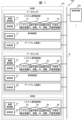
- FIG. 1 is a diagram illustrating an example of the overall configuration of a control service providing system to which the present embodiment is applied.
- FIG. 2 is a diagram showing system configuration information.
- FIG. 11 is a diagram showing operation requirement information.
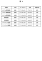
- FIG. 11 is a diagram showing device status information.
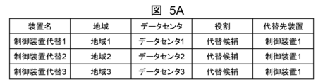
- FIG. 13 is a diagram showing alternate system management information.
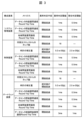
- FIG. 13 is a diagram showing alternative metrics information.
- FIG. 13 is a diagram showing a processing flow of a device management unit.
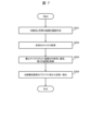
- FIG. 13 is a diagram showing a processing flow for a device management unit to create an alternate system.
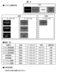
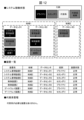
- FIG. 13 is a diagram showing a system management screen in a state before the control device enters a warning state and when the control system is operating normally (normal state).
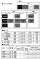
- FIG. 13 shows a system management screen when the control device is in a warning state.
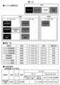
- FIG. 13 shows the system management screen when an alternative system is selected.
- FIG. 13 is a diagram showing a system management screen when the control device is in an abnormal state.
- FIG. 1 is a diagram showing an example of the overall configuration of a control service providing system 100 to which the present embodiment is applied.
- a control system 110 controls a control target 120.
- the control system 110 is provided as a cloud service, for example.
- the control system 110 exchanges control information and the like via a network N to control the control target 120.
- the controlled object 120 is, for example, an industrial plant.
- the industrial plant is not particularly limited, and examples thereof include steel plants, chemical plants, and other industrial plants.
- examples of the industrial plant include power plants that generate electricity using thermal power, hydroelectric power, atomic power, solar power, wind power, and the like.
- examples of the industrial plant include oil production plants that extract crude oil from oil wells, LNG plants that extract natural gas (LNG: Liquified Natural Gas) from gas fields, and oil refinery plants that refine crude oil.
- the control system 110 receives detection signals from temperature sensors, pressure sensors, flow meters, and the like provided in equipment such as a crude oil heating furnace, a distillation tower, and a catalyst/hydrogenation desulfurization tower that constitute the oil refinery plant. Then, based on the detection signals, it transmits control signals that control the temperature, pressure, flow rate, opening and closing of valves, and the like of these equipment.
- the control system 110 is not limited to such industrial plants, and may be a railway control system that controls railway equipment.
- the control object 120 may be, for example, a railway signal, a switch (point), a railroad crossing, etc. Also, although only one control object 120 is shown in FIG. 1, multiple control objects 120 may be controlled.
- the control system 110 includes data centers 1 and 2 installed in a region 1.
- the data center 1 comprises a system management device 1, a control device 1, and a gateway device 1.
- the data center 2 comprises a system management device 2, a control device 2, and a gateway device 2.
- a system management device 3 is installed in the area 2.
- the system management devices 1 to 3, the control devices 1 and 2, and the gateway devices 1 and 2 are components that make up the control system 110, and are examples of computer resources. These are respectively referred to as virtual machines (VMs).
- the virtual machines are generally referred to as virtual machines (VMs). However, these may be physical machines. Also, virtual machines and physical machines may be mixed. Furthermore, containers may be used instead of virtual machines.
- the system management devices 1 to 3 manage the components of the control system 110.
- Each of the system management devices 1 to 3 can manage the control devices 1 and 2 and the gateway devices 1 and 2.
- the system management devices 1 to 3 can manage the control devices 1 and 2 and the gateway devices 1 and 2 across the frameworks of regions and data centers.
- the control devices 1 and 2 perform control decisions for the control target 120.
- the gateway devices 1 and 2 communicate with the control target 120.
- the control devices 1 and 2 exchange detection signals, control signals, and the like via the gateway devices 1 and 2 to control the control target 120.
- System management device 1 comprises a device management unit 11, a diagnosis unit 12, system configuration information 13, operational requirement information 14, device status information 15, and alternate system management information 16.
- system management device 2 comprises a device management unit 21, a diagnosis unit 22, system configuration information 23, operational requirement information 24, device status information 25, and alternate system management information 26.
- system management device 2 further comprises a device management unit 31, a diagnosis unit 32, system configuration information 33, operational requirement information 34, device status information 35, and alternate system management information 36.
- the control device 1 includes a diagnosis unit 17
- the control device 2 includes a diagnosis unit 27 .
- the gateway device 1 includes a diagnosis unit 18
- the control device 2 includes a diagnosis unit 28 .
- the device management units 11, 21, and 31 function as a switching unit that switches from the component in which the failure occurred to the selected component.
- the failure is an abnormal state, which is an example of the second stage.
- the degree of the failure worsens when the metrics become even worse than when they were in the warning state.
- the diagnostic units 12, 22, and 32 diagnose the metrics.
- the metrics are the numerical representation of the performance of the control system 110. In this embodiment, the metrics are either limited to a single component or span multiple components in the control system 110.
- the former are, for example, CPU (Central Processing Unit) performance and clock accuracy. Clock accuracy can be evaluated based on clock delay.
- the diagnostic unit 12 can determine that the greater the clock delay, the lower the clock accuracy. The latter corresponds to the communication performance between the respective components.
- the communication performance can be evaluated based on, for example, the operation time required for the cooperative operation between the components.
- the diagnostic unit 12 can determine that the longer this time, the greater the communication delay and the lower the communication performance.
- the diagnostic units 17, 27, 18, and 28 also have the same function. These diagnostic units function as metrics acquisition units that acquire metrics of computer resources used to control the control target 120.
- FIG. 2 is a diagram showing the system configuration information 13, 23, and 33.
- the system configuration information 13 , 23 , and 33 is information about the components that make up the control system 110 .
- the illustrated system configuration information 13, 23, 33 consists of items of components, system configuration, and communication destination.
- Components are types of components, and are either a system management device, a control device, or a gateway device.
- System configuration is information on redundant configuration.
- a master-slave system indicates that it consists of a master system (active device) and a slave system (backup device), and a three-device system indicates that it consists of a master system (active device) and two slave systems (backup devices).
- Communication destination is information that indicates the party with which each component communicates.
- FIG. 3 is a diagram showing the operation requirement information 14, 24, and 34.
- the operation requirement information 14, 24, and 34 is information on the metrics requirements required for each component.
- the illustrated operation requirement information 14, 24, 34 includes items of components, metrics, abnormality determination means, abnormality determination threshold, and warning determination threshold.
- the components are types of components, and are one of a system management device, a control device, and a gateway device.
- the metrics, abnormality determination means, abnormality determination threshold, and warning determination threshold are determined for each component. Among these, the metrics are items of metrics required for each component.
- the abnormality determination means is a method for determining whether each component is in an abnormal state or not, and a method for determining whether each component is in a warning state or not.
- this is "exceeding threshold"
- the diagnostic units 12, 22, 32 determine that the component is in an abnormal state when the abnormality determination threshold is exceeded.
- the diagnostic units 12, 22, 32 determine that the component is in a warning state when the warning determination threshold is exceeded.
- determining that the component is in an abnormal state or a warning state it may be determined that the component is in these states when the threshold is exceeded once, but it may also be determined that the component is in these states when the threshold is exceeded a certain number of times in succession.
- intra-datacenter inter-device communication is the operation time required for cooperative operations between components in the same data center. For example, this corresponds to the operation time between system management device 1 and control device 1, and the operation time required between system management device 1 and gateway device 1.
- Inter-datacenter inter-device communication is the operation time required for cooperative operations between components in different data centers. For example, this corresponds to the operation time between system management device 1 and system management device 2.
- Inter-region inter-device communication is the operation time required between components in different regions. For example, this corresponds to the operation time between system management device 1 in region 1 and system management device 3 in region 2.
- the number of hops from the synchronization source clock is the number of hops from the device that is the synchronization source of the clock.
- the clock correction amount is the clock correction amount.
- FIG. 4 is a diagram showing the device status information 15, 25, and 35.
- the device status information 15, 25, and 35 is information about the operating status of each component.
- the illustrated device status information 15, 25, 35 consists of the items of device name, region, data center, role, and device status.
- the device name is the device name of the component, and is the above-mentioned system management devices 1 to 3, gateway devices 1 and 2, and gateway devices 1 and 2.
- the region is the geographical location where the data center is installed.
- the data center is the name of the data center where each component is installed, and is any one of data centers 1 to 3.
- the role indicates whether the operating status of each component is primary or secondary.
- the device status indicates whether the operating status of the device is normal or abnormal.
- FIG. 4 shows that all the components are normal.
- FIG. 6 is a diagram showing a processing flow of the device management unit 11.
- the device management unit 11 is the primary unit, and performs a series of processes.
- the diagnostic unit 12 diagnoses the metrics of each device (each component) in the system management device 1, and the device management unit 11 acquires the metrics of each device from the diagnostic unit 12 (S101).
- the device manager 11 judges whether or not there is an abnormality in each device based on the metrics of each device (S102). This is executed for each device according to the following flow (S103).
- the device management unit 11 judges whether or not an abnormality or warning has occurred in one device (S104). If an abnormality or warning has occurred (Y (Yes) in S104), the device management unit 11 refers to the device status information 15 and determines whether or not there is an alternative system for the device in which the abnormality or warning has occurred (S105). As a result, if there is no alternate system (N (No) in S105), the device manager 11 creates an alternate system (S106). If there is an alternative system in S104 (Y in S105) and after S106, the device manager 11 judges whether or not there is an abnormality (S107). As a result, if no abnormality is found (N in S107), the device manager 11 ends the processing in the device.
- the device manager 11 stops and deletes the abnormal system (S108). Furthermore, the device manager 11 promotes the existing secondary device to a primary device (S109), i.e., the device that was a secondary device for the device in which the abnormality occurred becomes a primary device. Then, the device manager 11 restores the alternate system as the secondary system (S110).
- the device manager 11 judges whether or not the device status information includes an alternative system for the device (S111). If there is an alternative system for the device (Y in S111), the alternative system is deleted (S112). This case corresponds to, for example, a case in which the metrics of the device have decreased, a warning has been issued, but then the metrics have recovered and the warning has been lifted. On the other hand, if there is no alternative system for the device (N in S111), the process for the device is terminated.
- the device manager 11 selects a computer resource to replace the failed computer resource when the device manager 11 detects the first stage of the failure.
- the first stage is a stage in which a warning state occurs.
- the device manager 11 can be said to switch to the selected device when it detects a second stage in which the metrics have decreased from the first stage, indicating a fault.
- the second stage is the stage in which an abnormality occurs.
- the device management unit 11 after selecting a device to replace the failed device, releases the preparation of the selected device when the warning state is resolved.
- the device management unit 11 makes the device that was the secondary device of the failed device the primary device, and the selected alternative system the secondary device.
- FIG. 7 is a diagram showing a processing flow for creating an alternate system by the device management unit 11. That is, FIG. 7 is a diagram for explaining in detail S105 in FIG.
- the device manager 11 creates a plurality of devices equivalent to the target system (the component in which an abnormality or warning has occurred) (S201). That is, the device manager 11 prepares a plurality of replacement candidates.
- the device manager 11 acquires the metrics for each system created in S201 (S202). That is, the device manager 11 acquires the metrics for each of the multiple replacement candidates. Specifically, the device manager 11 acquires the clock delay as a measure of clock accuracy, and the operation time required for cooperative operation between devices as a measure of communication performance.
- the device management unit 11 may also preselect areas for preparing replacement candidates for each predetermined period.
- the time required for cooperative operation varies depending on, for example, the regions and the time for communication. Therefore, the device management unit 11 obtains metrics from the diagnosis unit 12 for each predetermined period and preselects areas for preparing replacement candidates. This makes it possible to preselect replacement candidates with good metrics.
- (1) Simply choose the one with the best metrics.
- (1) is the method performed in S203 of Fig. 7.
- control device alternative 1 when comparing control device alternative 1 and control device alternative 2, the number of hops from the synchronization source clock, the amount of clock correction, and inter-regional device communication are equivalent.
- control device alternative 1 is better than control device alternative 2 for communication between devices within a data center and between devices between data centers. Therefore, control device alternative 1 is selected.
- a device with higher real-time performance can be adopted.
- the alternative control device 3 is not subject to comparison of metrics because the number of hops from the synchronization source clock is too large and does not satisfy the requirements of the abnormality determination means in FIG. 5B.
- the metrics are the communication performance between devices, and the device management unit 11 can be said to select the alternative candidate with the best communication performance as an alternative system to replace the failed device.
- control device 1 Prioritize data centers that meet the metric requirements and do not have a secondary for the failed device. For example, if the secondary of control device 1 is control device 2, then the controller selects those belonging to data centers 1 and 3, which are data centers other than data center 2 to which control device 2 belongs. In this case, control device alternative 1 belonging to data center 1 and control device alternative 3 belonging to data center 3 are selected. In this case, the devices can be distributed and availability can be increased.
- the device management unit 11 can be said to select an alternative system to replace the failed device based on the area in which the computer resource is installed, in addition to the metrics for the alternative candidate. Also, in method (2), the device management unit 11 can be said to select a device in the same data center as the area as the alternative system. Furthermore, in method (3), the device management unit 11 can be said to select a device in a data center in which there is no secondary for the failed computer resource as the area as the alternative system.
- the metric is the amount of clock correction
- the device management unit 11 can be said to select an alternative candidate whose clock correction amount is close to that of the secondary device of the failed device as an alternative system to replace the failed device.
- ⁇ System Management Screen Explanation> 8 to 12 are diagrams showing the system management screen.
- the metric of the control device 1 drops and goes into a warning state, and the metric further drops and goes into an abnormal state, so that the control device alternative 1 is selected as the alternative system.
- FIG. 8 is a diagram showing the system management screen in a state before the control device 1 goes into a warning state and in which the control system 110 is operating normally (normal state).
- the system operation status is displayed in the upper part. This shows that the system management device 1, control device 1, and gateway device 1 installed in data center 1 in region 1 are primary. Also, it shows that the system management device 2, system management device 3, control device 2, and gateway device 2 installed in data center 2 in region 1 are secondary.
- a device list is displayed in the middle section. The device list is the same as that in Fig. 4, and the device name, region, data center, role, and device status are displayed for each component of the system management devices 1 to 3, control devices 1 and 2, and gateway devices 1 and 2.
- Fig. 4 the device name, region, data center, role, and device status are displayed for each component of the system management devices 1 to 3, control devices 1 and 2, and gateway devices 1 and 2.
- FIG. 8 shows that all the components are normal. Furthermore, in the illustrated system management screen, information on alternate system management is displayed in the lower part. In Fig. 8, since all components are normal, an alternate system has not been created and the message "There is no device requiring an alternate system" is displayed.
- FIG. 9 shows the system management screen when the control device 1 is in a warning state.
- the system operation status in the upper part indicates that alternative candidates have been prepared.
- alternative control devices 1 to 3 have been prepared as alternative candidates in data centers 1 to 3, respectively.
- the device list in the middle section indicates that the device status of the control device 1 has become a warning.
- the alternate system management in the lower part displays the device name, region, data center, role, and metrics of control device alternates 1 to 3. Note that a selection button may be provided on this alternate system management screen so that the system administrator can select an alternate system.
- FIG. 10 shows the system management screen when the alternate system is selected.
- the system operation status in the upper part indicates that control device alternative 1 has been selected as the alternative system.
- the one with the best metrics is selected as the alternative system.
- the device list in the middle section indicates that the device status of the control device 1 remains in a warning state.
- the device name, region, data center, role, and metrics of the selected alternate control device 1 are displayed.
- FIG. 11 shows the system management screen when the control device 1 is in an abnormal state.
- the device list in the middle section indicates that the device status of the control device 1 has transitioned from warning to abnormal.
- the other screens are the same as those in FIG.
- FIG. 12 shows the system management screen when switching to the alternate system.
- the system operating status in the upper part indicates that the control device 2 has been promoted to the primary device, and the alternative control device 1 has become the secondary control device 3.
- the device list in the middle section shows that control device 3 has been added in place of control device 1. The device status of control device 3 is normal.
- the message "There are no devices requiring an alternate system" is displayed.
- control system 110 described above can meet the punctuality requirements of an application even when the management of components, which are an example of computer resources, cannot be strictly performed.
- the types of components which are examples of computer resources, were a system management device, a control device, and a gateway device, but this is not limited to these, and the type and number of components can be freely set as long as the control target 120 can be controlled and the configuration has redundancy.
- the control system 110 was exemplified as a virtual machine running on a public cloud, but this is not limited to these, and it does not have to be something that runs on a cloud.
- control system 110 The above-described processes performed by the control system 110 are realized by the cooperation of software and hardware resources. That is, a processor in a computer constituting the control system 110 loads software for realizing each of the above-described functions into a main storage device, executes the software, and realizes each of these functions. Therefore, the processing performed by the control system 110 can be considered as a control method in which a processor executes a program recorded in memory to obtain metrics of the components used to control the control target 120, detects a failure of the component based on the metrics, prepares multiple replacement candidates for the failed component, selects a component to replace the failed component from among the replacement candidates based on the metrics for the multiple replacement candidates, and switches from the failed component to the selected component. In this case, this processing does not have to be performed by a single computer device, but may be realized by a plurality of computer devices.
Landscapes
- Engineering & Computer Science (AREA)
- Theoretical Computer Science (AREA)
- Quality & Reliability (AREA)
- Physics & Mathematics (AREA)
- General Engineering & Computer Science (AREA)
- General Physics & Mathematics (AREA)
- Hardware Redundancy (AREA)
Abstract
Description
しかしながら、制御システムとして、例えば、仮想マシンを使用する場合、計算機資源の管理を厳密にできず、仮想マシンのデプロイ先によっては、アプリケーションが求める定時性の要件を満たせないことがある。
本発明は、計算機資源の管理を厳密にできない場合でも、アプリケーションが求める定時性要件を満たすことができる制御システム、制御方法、制御サービス提供システムを提供することを目的とする。
また、準備部は、第1の段階を検知したときに、障害が発生した計算機資源から選択された計算機資源に内部の状態をコピーし、双方の状態を一致化させるようにできる。この場合、第2の段階で系切替を行った後、即座にメトリクスのよい計算機資源をセカンダリ等として利用することができる。
さらに、準備部は、状態を一致化させた後に、障害が発生した計算機資源に入力される情報を取得し、状態の一致化を維持するようにできる。この場合、メトリクスのよい計算機資源をさらに迅速に利用することができる。
またさらに、障害は、時計遅れおよび通信遅れの少なくとも一方とすることができる。この場合、制御対象を制御するのに問題が生じやすい事象に対し対応することができる。
また、準備部は、障害が生じた計算機資源の替わりとなる計算機資源を選択した後に、第1の段階の障害が解消したときは、選択された計算機資源の用意を解除するようにできる。この場合、メトリクスが回復したときは、選択された計算機資源の用意を解除できる。
さらに、メトリクスは、計算機資源同士の通信性能であり、準備部は、通信性能が最も良好な代替候補を、障害が生じた計算機資源の替わりとなる計算機資源として選択するようにできる。この場合、制御システムに求められる定時性を確保しやすくなる。
そして、メトリクスは、時計の補正量であり、準備部は、時計の補正量が障害が生じた計算機資源のセカンダリと近い代替候補を、障害が生じた計算機資源の替わりとなる計算機資源として選択するようにできる。この場合、セカンダリから昇格したプライマリと、セカンダリとなる代替系との間で時刻のずれが起きにくくなる。
また、準備部は、代替候補についてのメトリクスに加え、計算機資源が設置されるエリアに基づき、障害が生じた計算機資源の替わりとなる計算機資源を選択するようにできる。この場合、可用性を高めることができる。
さらに、エリアとして、同じデータセンタ内の計算機資源を選択するようにできる。この場合、予め設計された装置配置の分散度合いを維持でき、可用性を高めることができる。
またさらに、準備部は、エリアとして、障害が生じた計算機資源のセカンダリが存在しないデータセンタ内の計算機資源を選択するようにできる。この場合、計算機資源が分散配置でき、可用性を高めることができる。
また、準備部は、代替候補を準備するエリアを予め定められた期間毎に予め選定するようにできる。この場合、メトリクスがよいエリアに配される計算機資源を予め選定しておくことができる。
さらに、切替部は、障害が生じた計算機資源のセカンダリとなっていた計算機資源をプライマリとし、選択された計算機資源をセカンダリとするようにできる。この場合、メトリクスがよい計算機資源をセカンダリとして割り当てることができる。
<制御サービス提供システム100の全体説明>
図1は、本実施の形態が適用される制御サービス提供システム100の全体構成例を示した図である。
制御サービス提供システム100では、制御システム110が制御対象120を制御する。制御システム110は、例えば、クラウド上のサービスとして提供される。そして、ネットワークNを介して、制御情報等のやりとりを行い、制御対象120を制御する。
データセンタ1は、システム管理装置1、制御装置1およびゲートウェイ装置1を備える。さらに、データセンタ2は、システム管理装置2、制御装置2およびゲートウェイ装置2を備える。また、地域2には、システム管理装置3が設置される。システム管理装置1~3、制御装置1,2、ゲートウェイ装置1,2は、制御システム110を構成する構成要素であり、計算機資源(計算機リソース)の一例である。これらは、それぞれ仮想マシン(VM:
Virtual Machine)である。ただし、これらは物理マシンであってもよい。また、仮想マシンと物理マシンとが混在していてもよい。さらに、仮想マシンの代わりにコンテナを使用してもよい。
制御装置1,2は、制御対象120に対する制御判断を行う。また、ゲートウェイ装置1,2は、制御対象120との通信を行う。制御装置1,2は、ゲートウェイ装置1,2を介して、検知信号や制御信号等のやりとりを行い、制御対象120を制御する。
制御装置1は、診断部17を備え、制御装置2は、診断部27を備える。
ゲートウェイ装置1は、診断部18を備え、制御装置2は、診断部28を備える。
このとき装置管理部11,21,31は、例えば、予め定められた要件によりそれぞれの代替候補のメトリクスを比較し、最も良好なものを選択する。また、装置管理部11,21,31は、障害の程度が低下し、異常が生じた場合、障害が生じた構成要素から、選択された構成要素に切り替える切替部として機能する。この場合、障害は、第2の段階の一例である異常状態である。また、障害の程度が悪化とは、メトリクスが警告状態のときよりもさらに低下した状態になった場合である。
システム構成情報13,23,33は、制御システム110を構成する構成要素についての情報である。
図示するシステム構成情報13,23,33は、構成要素、系の構成、通信先の項目からなる。構成要素は、構成要素の種別であり、システム管理装置、制御装置およびゲートウェイ装置の何れか1つになる。系の構成は、冗長構成の情報である。主従系は、主系(現用機)と従系(予備機)とからなることを示し、3台系は、主系(現用機)と2つの従系(予備機)とからなることを示す。通信先は、それぞれの構成要素が通信を行う相手を示す情報である。
動作要件情報14,24,34は、それぞれの構成要素に求められるメトリクスの要件についての情報である。
図示する動作要件情報14,24,34は、構成要素、メトリクス、異常判定手段、異常判定閾値、警告判定閾値の各項目からなる。構成要素は、構成要素の種別であり、システム管理装置、制御装置およびゲートウェイ装置の何れか1つになる。そして、構成要素毎に、メトリクス、異常判定手段、異常判定閾値、警告判定閾値が定められる。このうち、メトリクスは、構成要素毎に求められるメトリクスの項目である。また、異常判定手段は、各構成要素が異常状態であるか否かを判定する方法、警告状態であるか否かを判定する方法である。これが、例えば、「閾値超過」であれば、予め定められた閾値を超えたときに、異常状態あるいは警告状態であると判定することを意味する。即ち、診断部12,22,32は、異常判定閾値を超えたときに異常状態であると判定する。また、診断部12,22,32は、警告判定閾値を超えたときに警告状態であると判定する。なお、異常状態あるいは警告状態であると判定する際に、1回閾値を超えたときにこれらの状態になったと判定してもよいが、一定回数連続して閾値を超えたときにこれらの状態になったと判定することもできる。
装置状態情報15,25,35は、それぞれの構成要素の動作状態についての情報である。
図示する装置状態情報15,25,35は、装置名、地域、データセンタ、役割、装置状態の各項目からなる。装置名は、構成要素の装置名であり、上述したシステム管理装置1~3、ゲートウェイ装置1,2、ゲートウェイ装置1,2である。地域は、データセンタが設置される地理的な場所である。データセンタは、各構成要素が設置されるデータセンタの名称であり、データセンタ1~3の何れかである。役割は、各構成要素の動作状態が、プライマリであるか、セカンダリであるかについて示す。装置状態は、装置の動作状態が、正常であるか、異常であるかについて示す。図4では、全ての構成要素が正常であることを示している。
代替系管理情報16,26,36は、代替候補となる構成要素についての情報である。
図示する代替系管理情報16,26,36は、装置名、地域、データセンタ、役割、代替先装置の各項目からなる。装置名は、代替候補となる構成要素の装置名である。ここでは、代替候補となる構成要素が、制御装置代替1~3であることを意味する。地域は、データセンタが設置される地理的な場所である。データセンタは、代替候補となる各構成要素が設置されるデータセンタの名称であり、データセンタ1~3の何れかである。役割は、これらの構成要素の役割であり、代替候補であることを示している。代替先装置は、図4に示した場合のように、各構成要素に障害が生じていない初期状態では空欄であるが、何れかの構成要素に障害が生じたときに、障害が生じた構成要素の装置名が入る。この場合、制御装置1に障害が発生した場合を示す。
代替系メトリクス情報は、代替候補となる構成要素のメトリクス情報である。
図示する代替系メトリクス情報は、装置名、メトリクス、異常判定手段、最新値、メトリクス更新日時の各項目からなる。装置名は、代替候補となる構成要素の装置名であり、図5Aの制御装置代替1~3である。メトリクスは、代替候補となる構成要素毎に求められるメトリクスの項目である。異常判定手段は、代替候補となる構成要素が異常であるか否かを判定する方法である。最新値は、代替候補となる構成要素に対する最新のメトリクスである。メトリクス更新日時は、メトリクスの最新値を取得した日時である。
図6は、装置管理部11の処理フローを示した図である。
なお、図6では、装置管理部11がプライマリであり、装置管理部11が、一連の処理を行う場合について示している。
まず、診断部12が、システム管理装置1内の各装置(各構成要素)のメトリクスの診断を行い、装置管理部11は、診断部12から各装置のメトリクスを取得する(S101)。
次に、装置管理部11は、各装置のメトリクスを基に、各装置に異常があるか否かを判定する(S102)。これは、以下のようなフローで装置毎に実行する(S103)。
そして、異常または警告が生じている場合(S104でY(Yes))、装置管理部11は、装置状態情報15を参照し、異常または警告が生じている当該装置に代替系があるか否かを判断する(S105)。
その結果、代替系がない場合(S105でN(No))、装置管理部11は、代替系を作成する(S106)。
S104で代替系がある場合(S105でY)、およびS106の後は、装置管理部11は、異常があるか否かを判断する(S107)。
その結果、異常がない場合(S107でN)、装置管理部11は、当該装置における処理を終了する。
対して、異常がある場合(S107でY)、装置管理部11は、異常系の停止および削除を行う(S108)。
さらに、装置管理部11は、既存のセカンダリをプライマリに昇格させる(S109)。即ち、異常が生じた当該装置のセカンダリであった装置をプライマリにする。
そして、装置管理部11は、代替系をセカンダリとして復帰させる(S110)。
そして、当該装置の代替系があった場合(S111でY)、代替系を削除する(S112)。この場合は、例えば、当該装置のメトリクスが低下し、いったん警告が生じたが、その後、メトリクスが回復して、警告が解除された場合が該当する。
一方、当該装置の代替系がない場合(S111でN)、当該装置に対する処理を終了する。
また、S107~S110で説明したように、装置管理部11は、障害として第1の段階よりメトリクスが低下した第2の段階を検知したときに、選択された装置に切り替える、と言うことができる。第2の段階は、異常状態となる段階である。
さらに、S112で説明したように、装置管理部11は、障害が生じた装置の替わりとなる装置を選択した後に、警告状態が解消したときは、選択された装置の用意を解除する、と言うことができる。
またさらに、S109~S110で説明したように、装置管理部11は、障害が生じた装置のセカンダリとなっていた装置をプライマリとし、選択された代替系をセカンダリとする、と言うことができる。
まず、装置管理部11は、対象系(異常または警告が生じている構成要素)と同等の装置を複数作成する(S201)。即ち、装置管理部11は、複数の代替候補を準備する。
次に、装置管理部11は、S201で作成した各系のメトリクスを取得する(S202)。即ち、複数の代替候補のそれぞれのメトリクスを取得する。具体的には、装置管理部11は、クロックの精度として時計遅れや、通信性能として、装置間の協調動作にかかる動作所要時間等を取得する。
次に、装置管理部11は、最もメトリクスがよい装置を代替系に選定し、残りの装置を削除する(S203)。即ち、装置管理部11は、代替候補の中から最もメトリクスがよいものを、障害が生じた計算機資源の替わりとなる代替系として選択する。
さらに、装置管理部11は、当該構成要素のプライマリ系と状態を一致化させる(S204)。この場合、プライマリ系が持つメモリ情報をコピーし、内部状態を一致化させる。警告の段階で内部状態を一致化することで、異常が生じたときの系切替後、即座に素性の良い装置をセカンダリ系として復帰させることができる。また、内部状態を一致化した後、プライマリ(orセカンダリ)に入力されるデータを取得し、代替系とプライマリ(orセカンダリ)の内部状態の一致化を維持する。制御系だと、ブロードキャスト/マルチキャストによる通信が多用される。この場合は、ネットワークNに接続しただけで情報を横抜きできる。ユニキャストで通信が行われている場合は、プライマリ(orセカンダリ)から情報を流してもらうことで状態を一致化する。
以下、代替候補の中から代替系を選択する方法を、図5A、図5Bを参照しつつ、(1)~(4)により説明する。なおここでは、データセンタ1の制御装置1が警告状態となったときに、制御装置1の替わりとなる代替系を選択する場合について説明する。
(1)は、図7のS203で行った方法である。図5Bの例では、制御装置代替1と制御装置代替2とを比較した場合、同期元クロックからのホップ数、時計の補正量、地域間装置間通信は、同等である。一方、データセンタ内装置間、データセンタ間装置間は、制御装置代替2よりも制御装置代替1の方がよい。よって、制御装置代替1を選択する。この選択方法によれば、よりリアルタイム性の高い装置を採用することができる。
なお、制御装置代替3は、同期元クロックからのホップ数が大きすぎ、図5Bの異常判定手段の要件を満たさないため、メトリクスの比較の対象とはならない。
(1)の方法では、メトリクスは、装置同士の通信性能であり、装置管理部11は、通信性能が最も良好な代替候補を、障害が生じた装置の替わりとなる代替系として選択する、と言うこともできる。
図5Aの例では、制御装置代替1と制御装置代替2とを比較した場合、制御装置代替1は、制御装置1と同じデータセンタ1内にあるが、制御装置代替2は、制御装置1と異なるデータセンタ2内にある。よって制御装置代替1を選択する。この選択方法によれば、予め設計された装置配置の分散度合いを維持でき、可用性を高めることができる。
例えば、制御装置1のセカンダリが制御装置2だったとすると、制御装置2が属するデータセンタ2以外のデータセンタであるデータセンタ1,3に属するものを選択する。この場合、データセンタ1に属する制御装置代替1やデータセンタ3に属する制御装置代替3を選択する。
この場合、装置が分散配置でき、可用性を高めることができる。
例えば、制御装置1のセカンダリが制御装置2だったとすると、制御装置2の時計の補正量が近いものを、制御装置代替1~3の中から選択する。
この場合、セカンダリから昇格したプライマリと、セカンダリとなる代替系との間で時刻のずれが起きにくくなる。これにより周期実行するプログラムの実行タイミングと入力データの受信タイミングのずれによる状態の不一致が起きにくくなる。
(4)の方法では、メトリクスは、時計の補正量であり、装置管理部11は、時計の補正量が障害が生じた装置のセカンダリと近い代替候補を、障害が生じた装置の替わりとなる代替系として選択する、と言うこともできる。
図8~12は、システム管理画面について示した図である。なおここでは、制御装置1のメトリクスが低下して警告状態となり、さらにメトリクスが低下することで異常状態になることで、制御装置代替1が代替系として選択された場合を例に取り説明を行う。
図示するシステム管理画面では、上段部にシステム稼働状態が表示される。これによれば、地域1のデータセンタ1に設置される、システム管理装置1、制御装置1、ゲートウェイ装置1がプライマリであることを示す。また地域1のデータセンタ2に設置される、システム管理装置2、システム管理装置3、制御装置2、ゲートウェイ装置2がセカンダリであることを示す。
また、図示するシステム管理画面では、中段部に装置一覧が表示される。装置一覧は、図4と同様であり、装置名、地域、データセンタ、役割、装置状態が、システム管理装置1~3、制御装置1,2、ゲートウェイ装置1,2のそれぞれの構成要素毎に表示される。図8では、全ての構成要素が正常であることを示す。
さらに、図示するシステム管理画面では、下段部に代替系管理の情報が表示される。図8では、全ての構成要素が正常であるので、代替系は作成されておらず、「代替系が必要な装置はありません。」のメッセージが表示されている。
図示するシステム管理画面では、上段部のシステム稼働状態で、代替候補が準備されたことを示す。この場合、制御装置代替1~3が、データセンタ1~3にそれぞれ代替候補として準備されたことを示す。
また、図示するシステム管理画面では、中段部の装置一覧で、制御装置1の装置状態が、警告になったことを示す。
さらに、図示するシステム管理画面では、下段部の代替系管理で、制御装置代替1~3の、装置名、地域、データセンタ、役割、メトリクスが表示される。なお、この代替系管理の画面中に選択ボタンを設け、システム管理者が代替系を選択してもよい。
図示するシステム管理画面では、上段部のシステム稼働状態で、制御装置代替1が代替系として選択されたことを示す。この場合、制御装置代替1~3の中で、メトリクスが最もよいものを代替系として選択している。
また、図示するシステム管理画面では、中段部の装置一覧で、制御装置1の装置状態が、警告のままであることを示す。
さらに、図示するシステム管理画面では、下段部の代替系管理で、選択された制御装置代替1の、装置名、地域、データセンタ、役割、メトリクスが表示される。
図示するシステム管理画面では、中段部の装置一覧で、制御装置1の装置状態が、警告から異常に移行したことを示す。なお、他の画面は、図10と同様である。
図示するシステム管理画面では、上段部のシステム稼働状態で、制御装置2が、プライマリに昇格したことを示す。また、制御装置代替1が、制御装置3としてセカンダリになったことを示す。
また、図示するシステム管理画面では、中段部の装置一覧で、制御装置1の替わりに制御装置3が入ったことを示す。なお、制御装置3の装置状態は、正常である。
さらに、図示するシステム管理画面では、下段部の代替系管理で、全ての構成要素が正常であるので、「代替系が必要な装置はありません。」のメッセージが表示されている。
以上説明を行った制御システム110が行う処理は、ソフトウェアとハードウェア資源とが協働することにより実現される。即ち、制御システム110を構成するコンピュータ内部のプロセッサが、上述した各機能を実現するソフトウェアを主記憶装置にロードして実行し、これらの各機能を実現させる。
よって、制御システム110が行う処理は、プロセッサがメモリに記録されたプログラムを実行することにより、制御対象120に対し制御を行うために使用している構成要素のメトリクスを取得し、メトリクスを基に構成要素の障害を検知し、障害が生じた構成要素の代替候補を複数準備するとともに、複数の代替候補についてのメトリクスを基に、代替候補の中から、障害が生じた構成要素の替わりとなる構成要素を選択し、障害が生じた構成要素から、選択された構成要素に切り替える、制御方法と捉えることができる。
この場合、1台のコンピュータ装置によりこの処理を行う必要はなく、複数台のコンピュータ装置により実現してもよい。
Claims (15)
- 制御対象に対し制御を行うために使用している計算機資源のメトリクスを取得するメトリクス取得部と、
前記メトリクスを基に計算機資源の障害を検知し、障害が生じた計算機資源の代替候補を複数準備するとともに、複数の前記代替候補についてのメトリクスを基に、前記代替候補の中から、障害が生じた計算機資源の替わりとなる計算機資源を選択する準備部と、
障害が生じた計算機資源から、選択された計算機資源に切り替える切替部と、
を備える制御システム。 - 前記準備部は、前記障害として第1の段階を検知したときに、障害が生じた計算機資源の替わりとなる計算機資源を選択し、
前記切替部は、前記障害として前記第1の段階より前記メトリクスが低下した第2の段階を検知したときに、選択された計算機資源に切り替える請求項1に記載の制御システム。 - 前記準備部は、前記第1の段階を検知したときに、障害が発生した計算機資源から選択された計算機資源に内部の状態をコピーし、双方の状態を一致化させる請求項2に記載の制御システム。
- 前記準備部は、状態を一致化させた後に、障害が発生した計算機資源に入力される情報を取得し、状態の一致化を維持する請求項3に記載の制御システム。
- 前記障害は、時計遅れおよび通信遅れの少なくとも一方である請求項2に記載の制御システム。
- 前記準備部は、障害が生じた計算機資源の替わりとなる計算機資源を選択した後に、前記第1の段階の障害が解消したときは、選択された計算機資源の用意を解除する請求項2に記載の制御システム。
- 前記メトリクスは、計算機資源同士の通信性能であり、
前記準備部は、前記通信性能が最も良好な前記代替候補を、障害が生じた計算機資源の替わりとなる計算機資源として選択する請求項1に記載の制御システム。 - 前記メトリクスは、時計の補正量であり、
前記準備部は、前記時計の補正量が障害が生じた計算機資源のセカンダリと近い前記代替候補を、障害が生じた計算機資源の替わりとなる計算機資源として選択する請求項1に記載の制御システム。 - 前記準備部は、前記代替候補についてのメトリクスに加え、計算機資源が設置されるエリアに基づき、障害が生じた計算機資源の替わりとなる計算機資源を選択する請求項1に記載の制御システム。
- 前記準備部は、前記エリアとして、同じデータセンタ内の計算機資源を選択する請求項9に記載の制御システム。
- 前記準備部は、前記エリアとして、障害が生じた計算機資源のセカンダリが存在しないデータセンタ内の計算機資源を選択する請求項9に記載の制御システム。
- 前記準備部は、前記代替候補を準備するエリアを予め定められた期間毎に予め選定する請求項1に記載の制御システム。
- 前記切替部は、障害が生じた計算機資源のセカンダリとなっていた計算機資源をプライマリとし、選択された計算機資源をセカンダリとする請求項1に記載の制御システム。
- プロセッサがメモリに記録されたプログラムを実行することにより、
制御対象に対し制御を行うために使用している計算機資源のメトリクスを取得し、
前記メトリクスを基に計算機資源の障害を検知し、障害が生じた計算機資源の代替候補を複数準備するとともに、複数の前記代替候補についてのメトリクスを基に、前記代替候補の中から、障害が生じた計算機資源の替わりとなる計算機資源を選択し、
障害が生じた計算機資源から、選択された計算機資源に切り替える、
制御方法。 - 制御対象と、前記制御対象を制御する制御システムと、
を備え、
前記制御システムは、
前記制御対象に対し制御を行うために使用している計算機資源のメトリクスを取得するメトリクス取得部と、
前記メトリクスを基に計算機資源の障害を検知し、障害が生じた計算機資源の代替候補を複数準備するとともに、複数の前記代替候補についてのメトリクスを基に、前記代替候補の中から、障害が生じた計算機資源の替わりとなる計算機資源を選択する準備部と、
障害が生じた計算機資源から、選択された計算機資源に切り替える切替部と、
を備える制御サービス提供システム。
Priority Applications (1)
| Application Number | Priority Date | Filing Date | Title |
|---|---|---|---|
| EP24819139.7A EP4726553A1 (en) | 2023-06-09 | 2024-05-20 | Control system, control method, and control service provision system |
Applications Claiming Priority (2)
| Application Number | Priority Date | Filing Date | Title |
|---|---|---|---|
| JP2023-095759 | 2023-06-09 | ||
| JP2023095759A JP2024176898A (ja) | 2023-06-09 | 2023-06-09 | 制御システム、制御方法および制御サービス提供システム |
Publications (1)
| Publication Number | Publication Date |
|---|---|
| WO2024252906A1 true WO2024252906A1 (ja) | 2024-12-12 |
Family
ID=93795204
Family Applications (1)
| Application Number | Title | Priority Date | Filing Date |
|---|---|---|---|
| PCT/JP2024/018520 Ceased WO2024252906A1 (ja) | 2023-06-09 | 2024-05-20 | 制御システム、制御方法および制御サービス提供システム |
Country Status (3)
| Country | Link |
|---|---|
| EP (1) | EP4726553A1 (ja) |
| JP (1) | JP2024176898A (ja) |
| WO (1) | WO2024252906A1 (ja) |
Citations (6)
| Publication number | Priority date | Publication date | Assignee | Title |
|---|---|---|---|---|
| JP2009265805A (ja) * | 2008-04-23 | 2009-11-12 | Hitachi Ltd | フェイルオーバ方法、プログラム、フェイルオーバ装置およびフェイルオーバシステム |
| JP2012133824A (ja) * | 2012-04-12 | 2012-07-12 | Hitachi Ltd | サーバ切り替え方法、およびサーバシステム |
| JP2012185560A (ja) * | 2011-03-03 | 2012-09-27 | Nec Corp | クラスタシステムおよびその制御方法 |
| WO2014006728A1 (ja) * | 2012-07-05 | 2014-01-09 | 富士通株式会社 | 処理装置、処理システム、及びプログラム |
| JP2018112829A (ja) | 2017-01-10 | 2018-07-19 | 横河電機株式会社 | クラウドサービス制御装置、クラウドサービス制御システム、クラウドサービス制御方法、クラウドサービス制御プログラム及び記録媒体 |
| WO2019159875A1 (ja) * | 2018-02-13 | 2019-08-22 | 日本電信電話株式会社 | 配置構成装置、および、配置構成方法 |
-
2023
- 2023-06-09 JP JP2023095759A patent/JP2024176898A/ja active Pending
-
2024
- 2024-05-20 EP EP24819139.7A patent/EP4726553A1/en active Pending
- 2024-05-20 WO PCT/JP2024/018520 patent/WO2024252906A1/ja not_active Ceased
Patent Citations (6)
| Publication number | Priority date | Publication date | Assignee | Title |
|---|---|---|---|---|
| JP2009265805A (ja) * | 2008-04-23 | 2009-11-12 | Hitachi Ltd | フェイルオーバ方法、プログラム、フェイルオーバ装置およびフェイルオーバシステム |
| JP2012185560A (ja) * | 2011-03-03 | 2012-09-27 | Nec Corp | クラスタシステムおよびその制御方法 |
| JP2012133824A (ja) * | 2012-04-12 | 2012-07-12 | Hitachi Ltd | サーバ切り替え方法、およびサーバシステム |
| WO2014006728A1 (ja) * | 2012-07-05 | 2014-01-09 | 富士通株式会社 | 処理装置、処理システム、及びプログラム |
| JP2018112829A (ja) | 2017-01-10 | 2018-07-19 | 横河電機株式会社 | クラウドサービス制御装置、クラウドサービス制御システム、クラウドサービス制御方法、クラウドサービス制御プログラム及び記録媒体 |
| WO2019159875A1 (ja) * | 2018-02-13 | 2019-08-22 | 日本電信電話株式会社 | 配置構成装置、および、配置構成方法 |
Non-Patent Citations (1)
| Title |
|---|
| See also references of EP4726553A1 |
Also Published As
| Publication number | Publication date |
|---|---|
| EP4726553A1 (en) | 2026-04-15 |
| JP2024176898A (ja) | 2024-12-19 |
Similar Documents
| Publication | Publication Date | Title |
|---|---|---|
| US11960588B2 (en) | Security services in a software defined control system | |
| US12078977B2 (en) | Discovery service in a software defined control system | |
| US20220404798A1 (en) | Software defined process control system and methods for industrial process plants | |
| US12111738B2 (en) | Managing data center failure events | |
| US20220404812A1 (en) | Discovery Service in a Software Defined Control System | |
| US12117801B2 (en) | Software defined process control system and methods for industrial process plants | |
| US12210329B2 (en) | Systems and methods for dynamically maintained redundancy and load balancing in software defined control systems for industrial process plants | |
| US20220404790A1 (en) | Visualization of a software defined process control system for industrial process plants | |
| JP2018116733A (ja) | プロセス工場において制御冗長性をアップグレードおよび提供するための方法と機器、置換装置 | |
| US20220404810A1 (en) | Visualization of A software defined process control system for industrial process plants | |
| US20220404813A1 (en) | Software defined control system including i/o server services that communicate with containerized services | |
| GB2612393A (en) | Systems and methods for dynamically maintained redundancy and load balancing in software defined control systems for industrial process plants | |
| US12449789B2 (en) | Security services in a software defined control system | |
| US20220404800A1 (en) | Discovery Service in a Software Defined Control System | |
| US12417120B2 (en) | Systems and methods for dynamically maintained redundancy and load balancing in software defined control systems for industrial process plants | |
| GB2612161A (en) | Systems and methods for associating modules in a software defined control system for industrial process plants | |
| GB2609089A (en) | Visualization of a software defined process control system for industrial process plants | |
| CN105812161A (zh) | 一种控制器故障备份方法和系统 | |
| US20220404807A1 (en) | Systems and Methods for Associating Modules in a Software Defined Control System for Industrial Process Plants | |
| GB2611846A (en) | Systems and methods for hierarchical organization of software defined process control systems for industrial process plants | |
| WO2024252906A1 (ja) | 制御システム、制御方法および制御サービス提供システム | |
| JP4879823B2 (ja) | 監視制御システム | |
| CN112612201A (zh) | 自动化系统、创建自动化系统的方法和计算机可读介质 | |
| CN113890850B (zh) | 路由容灾系统及方法 | |
| CN117234144A (zh) | 备份方法与plc系统 |
Legal Events
| Date | Code | Title | Description |
|---|---|---|---|
| 121 | Ep: the epo has been informed by wipo that ep was designated in this application |
Ref document number: 24819139 Country of ref document: EP Kind code of ref document: A1 |
|
| WWE | Wipo information: entry into national phase |
Ref document number: 2024819139 Country of ref document: EP |
|
| NENP | Non-entry into the national phase |
Ref country code: DE |
|
| ENP | Entry into the national phase |
Ref document number: 2024819139 Country of ref document: EP Effective date: 20260109 |
|
| ENP | Entry into the national phase |
Ref document number: 2024819139 Country of ref document: EP Effective date: 20260109 |
|
| ENP | Entry into the national phase |
Ref document number: 2024819139 Country of ref document: EP Effective date: 20260109 |
|
| ENP | Entry into the national phase |
Ref document number: 2024819139 Country of ref document: EP Effective date: 20260109 |
|
| ENP | Entry into the national phase |
Ref document number: 2024819139 Country of ref document: EP Effective date: 20260109 |
|
| WWP | Wipo information: published in national office |
Ref document number: 2024819139 Country of ref document: EP |