WO2024252786A1 - 画像処理装置、画像処理システム、画像処理方法、および、プログラム - Google Patents
画像処理装置、画像処理システム、画像処理方法、および、プログラム Download PDFInfo
- Publication number
- WO2024252786A1 WO2024252786A1 PCT/JP2024/014799 JP2024014799W WO2024252786A1 WO 2024252786 A1 WO2024252786 A1 WO 2024252786A1 JP 2024014799 W JP2024014799 W JP 2024014799W WO 2024252786 A1 WO2024252786 A1 WO 2024252786A1
- Authority
- WO
- WIPO (PCT)
- Prior art keywords
- image
- unit
- region
- luminance distribution
- image processing
- Prior art date
- Legal status (The legal status is an assumption and is not a legal conclusion. Google has not performed a legal analysis and makes no representation as to the accuracy of the status listed.)
- Ceased
Links
Images












Classifications
-
- G—PHYSICS
- G06—COMPUTING OR CALCULATING; COUNTING
- G06T—IMAGE DATA PROCESSING OR GENERATION, IN GENERAL
- G06T5/00—Image enhancement or restoration
- G06T5/50—Image enhancement or restoration using two or more images, e.g. averaging or subtraction
-
- H—ELECTRICITY
- H04—ELECTRIC COMMUNICATION TECHNIQUE
- H04N—PICTORIAL COMMUNICATION, e.g. TELEVISION
- H04N23/00—Cameras or camera modules comprising electronic image sensors; Control thereof
- H04N23/45—Cameras or camera modules comprising electronic image sensors; Control thereof for generating image signals from two or more image sensors being of different type or operating in different modes, e.g. with a CMOS sensor for moving images in combination with a charge-coupled device [CCD] for still images
-
- H—ELECTRICITY
- H04—ELECTRIC COMMUNICATION TECHNIQUE
- H04N—PICTORIAL COMMUNICATION, e.g. TELEVISION
- H04N23/00—Cameras or camera modules comprising electronic image sensors; Control thereof
- H04N23/56—Cameras or camera modules comprising electronic image sensors; Control thereof provided with illuminating means
-
- H—ELECTRICITY
- H04—ELECTRIC COMMUNICATION TECHNIQUE
- H04N—PICTORIAL COMMUNICATION, e.g. TELEVISION
- H04N23/00—Cameras or camera modules comprising electronic image sensors; Control thereof
- H04N23/60—Control of cameras or camera modules
-
- H—ELECTRICITY
- H04—ELECTRIC COMMUNICATION TECHNIQUE
- H04N—PICTORIAL COMMUNICATION, e.g. TELEVISION
- H04N23/00—Cameras or camera modules comprising electronic image sensors; Control thereof
- H04N23/70—Circuitry for compensating brightness variation in the scene
-
- H—ELECTRICITY
- H04—ELECTRIC COMMUNICATION TECHNIQUE
- H04N—PICTORIAL COMMUNICATION, e.g. TELEVISION
- H04N23/00—Cameras or camera modules comprising electronic image sensors; Control thereof
- H04N23/70—Circuitry for compensating brightness variation in the scene
- H04N23/71—Circuitry for evaluating the brightness variation
-
- H—ELECTRICITY
- H04—ELECTRIC COMMUNICATION TECHNIQUE
- H04N—PICTORIAL COMMUNICATION, e.g. TELEVISION
- H04N7/00—Television systems
- H04N7/18—Closed-circuit television [CCTV] systems, i.e. systems in which the video signal is not broadcast
Definitions
- This technology relates to an image processing device. More specifically, it relates to an image processing device, an image processing system, an image processing method, and a program for causing a computer to execute the method.
- Image processing using luminance distribution has been used in various fields for some time.
- a device has been proposed that assumes that the luminance distribution of a light source area is Gaussian-like, and matches a template created from the Gaussian distribution with the luminance distribution in an image (see, for example, Patent Document 1).
- this device an area whose luminance distribution is similar to the Gaussian distribution through matching is extracted as the light source area.
- the light source area is extracted by matching a template created from a Gaussian distribution with the luminance distribution in the image.
- the luminance distribution of the shadow area caused by the reflection of light from the light source may be similar to the Gaussian distribution, and therefore the area may be erroneously extracted as the light source area.
- the accuracy of the process for extracting the light source area decreases.
- This technology was developed in light of these circumstances, and aims to improve the processing accuracy of image processing devices that extract light source areas.
- the present technology has been made to solve the above-mentioned problems, and a first aspect thereof is an image processing device including a luminance distribution comparison unit that compares the luminance distribution of a first region in a first image and the luminance distribution of a second region in a second image, the first image and the second image being generated by shooting from a first direction and a second direction that are different from each other, and an image processing method for the device, as well as a program for causing a computer to execute the method. This has the effect of improving processing accuracy.
- an identical region determination unit may be further provided which determines whether each of a predetermined number of regions to be determined in the first image is identical to any of the regions in the second image based on the angle between the first direction and the second direction, and supplies the identical regions to the luminance distribution comparison unit as the first region and the second region. This provides the effect of comparing the luminance distributions of identical regions.
- an angle calculation unit may be further provided that calculates the angle between the first direction and the second direction based on the first image and the second image and supplies the calculated angle to the identical area determination unit. This provides the effect of calculating the angle from images captured by one imaging device.
- a luminance gradient determination unit may be further provided that supplies a region in the first image that resembles a specific luminance distribution to the identical region determination unit as the determination target region. This provides the effect of determining a region with a specific luminance distribution by the identical region determination unit.
- a luminance gradient classification unit may be further provided that classifies regions in the first image based on the comparison results of the luminance distribution comparison unit. This provides the effect of appropriately classifying regions.
- the device may further include a region of interest setting section that sets a region of interest in the first image based on the classification result of the luminance gradient classification section, and an AF (Auto Focus) control section that performs processing to focus on a subject in the region of interest.
- a region of interest setting section that sets a region of interest in the first image based on the classification result of the luminance gradient classification section
- an AF (Auto Focus) control section that performs processing to focus on a subject in the region of interest. This has the effect of improving focusing accuracy.
- the device may further include a photometry section that sets a photometry area in the first image based on the classification result of the luminance gradient classification section and measures the amount of light in the photometry area, and an exposure control section that controls the amount of exposure based on the measured amount of light. This provides the effect of controlling the amount of exposure to an appropriate value.
- an AWB Auto White Balance control unit
- AWB Auto White Balance
- an image generating unit may be further provided that generates an image based on the classification result of the luminance gradient classification unit. This provides the effect of generating a fluorescent image, etc.
- the image generating unit may generate a fluorescent image by extracting a fluorescent region from the first image, and a reflected image by extracting a region that does not correspond to the fluorescent region from the first image. This provides the effect of making it easier to distinguish between the fluorescent image and the shadow image.
- the image generating unit may generate an image in which fluorescent regions and shaded regions in the first image are filled with different colors. This provides the effect of making it easier to distinguish between the fluorescent image and the shaded image.
- the image generating unit may generate an image in which the fluorescent region in the first image is highlighted. This has the effect of making it easier to distinguish between the fluorescent image and the shadow image.
- a second aspect of the present technology is an image processing system including an excitation light source and an external processing device including a luminance distribution comparison unit that compares the luminance distribution of a first region in a first image and a luminance distribution of a second region in a second image, the first image and the second image being generated by photographing from a first direction and a second direction that are different from each other. This has the effect of improving the processing accuracy of the image processing system.
- an imaging device may be further provided that captures the first image and the second image in sequence. This provides the effect of calculating the angle from the images captured by one imaging device.
- a first imaging device that captures the first image from the first direction and a second imaging device that captures the second image from the second direction may be further provided. This provides the effect of eliminating the need to calculate angles.
- a third aspect of the present technology is an image processing system including an imaging device having a luminance distribution comparison unit that compares the luminance distribution of a first region in a first image and a luminance distribution of a second region in a second image, the first image and the second image being generated by capturing images from a first direction and a second direction that are different from each other, and an external processing device that processes images based on output data from the imaging device. This has the effect of improving the processing accuracy of the image processing system.
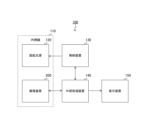
- FIG. 1 is a block diagram showing a configuration example of an image processing system according to a first embodiment of the present technology
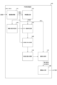
- 1 is a block diagram showing a configuration example of an external processing device according to a first embodiment of the present technology
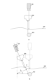
- 3 is a diagram illustrating an example of positions of an imaging device and an excitation light source according to the first embodiment of the present technology.
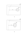
- FIG. FIG. 2 is a diagram showing an example of an input image according to the first embodiment of the present technology
- 11 is a diagram showing another example of the positions of the imaging device and the excitation light source according to the first embodiment of the present technology.
- FIG. FIG. 11 is a diagram showing another example of an input image in the first embodiment of the present technology.
- FIG. 1 is a diagram showing an example of a region in an image according to a first embodiment of the present technology
- 1A to 1C are diagrams for explaining a process of determining an identical region according to the first embodiment of the present technology
- 11 is a diagram showing an example of a determination result according to the first embodiment of the present technology
- FIG. FIG. 2 is a diagram illustrating an example of a luminance distribution according to the first embodiment of the present technology.
- FIG. 11 is a diagram illustrating an example of a classification result according to the first embodiment of the present technology.
- FIG. 2 is a diagram showing an example of an output image according to the first embodiment of the present technology;
- FIG. 11 is a diagram showing another example of an output image in the first embodiment of the present technology.
- FIG. 5 is a flowchart showing an example of an operation of the external processing device according to the first embodiment of the present technology.
- 1 is a block diagram showing an example configuration of an imaging device according to a first modified example of a first embodiment of the present technology
- 1 is a block diagram showing a configuration example of an external processing device according to a first modified example of the first embodiment of the present technology
- 13 is a block diagram showing a configuration example of an image processing unit in a second modified example of the first embodiment of the present technology.
- FIG. FIG. 11 is a block diagram showing a configuration example of an external processing device in a second modified example of the first embodiment of the present technology.
- 13 is a diagram illustrating an example of an imaging device and an excitation light source according to a second embodiment of the present technology.
- FIG. 13 is a flowchart illustrating an example of an operation of an external processing device according to a second embodiment of the present technology.
- FIG. 13 is a block diagram showing an example configuration of an imaging device according to a third embodiment of the present technology.
- FIG. 13 is a block diagram showing a configuration example of an image processing unit according to a third embodiment of the present technology.
- FIG. 13 is a diagram showing an example of an input image according to a third embodiment of the present technology.
- 13 is a flowchart showing an example of an operation of an image processing unit according to the third embodiment of the present technology.
- FIG. 13 is a block diagram illustrating an example configuration of an image processing unit in a first modified example of the third embodiment of the present technology.
- FIG. 13 is a block diagram illustrating an example configuration of an image processing unit in a second modified example of the third embodiment of the present technology.
- 1 is a diagram illustrating an example of a schematic configuration of an endoscopic surgery system.
- 2 is a block diagram showing an example of the functional configuration of a camera head and a CCU.
- FIG. 1 is a block diagram showing a schematic configuration example of a vehicle control system;
- FIG. 4 is an explanatory diagram showing an example of an installation position of an imaging unit.
- First embodiment (example of comparing luminance distribution) 2.
- Second embodiment (example of comparing luminance distributions using two imaging devices) 3.
- Third embodiment (example of comparing luminance distributions and adjusting focus) 4.
- Application to endoscopic surgery system 5.
- First embodiment is a block diagram showing an example of a configuration of an image processing system 100 according to an embodiment of the present technology.
- the image processing system 100 is a system used for surgery or examination using an endoscope, and includes an endoscope 110, a control device 130, an external processing device 140, and a display device 150.
- the endoscope 110 is composed of a telescope tube (not shown) whose tip is inserted into the patient's body cavity by a predetermined length, an imaging device 200 connected to the base end of the telescope tube, and an excitation light source 120.
- the excitation light source 120 emits light of a specific wavelength as excitation light to cause a fluorescent substance (such as a fluorescent reagent or a fluorescent antibody) to emit light.
- a fluorescent substance such as a fluorescent reagent or a fluorescent antibody
- a broadband light source such as a mercury arc or a tungsten halogen lamp, or a laser excitation source or an LED (Light-Emitting Diode) is used.
- the imaging device 200 captures images through photoelectric conversion.
- the imaging device 200 includes an optical system and a solid-state imaging element, and generates image data and transmits it to the external processing device 140.
- the control device 130 controls the devices and equipment within the image processing system 100, such as the endoscope 110, the external processing device 140, and the display device 150.
- the external processing device 140 performs various image processing operations on the image data from the imaging device 200.
- This external processing device 140 displays the processed image data on the display device 150.
- a personal computer or the like is used as the external processing device 140.
- the external processing device 140 is an example of an image processing device as described in the claims.
- the user can use fluorescence imaging during surgery or examination using an endoscope.
- fluorescence imaging a fluorescent substance that remains in a specific area inside the body (such as a tumor area) is administered to the patient, and the area is labeled.
- the excitation light source 120 irradiates excitation light according to the control of the control device 130, and generates fluorescence of a different wavelength from the excitation light in the labeled area.
- this area that emits fluorescence is referred to as the "fluorescent area.”
- Near-infrared light or infrared light is used as the fluorescence so that it can easily pass through the body.
- the imaging device 200 images the fluorescent area multiple times according to the user's operation. At this time, the user operates the endoscope 110 to capture at least two images from different directions.
- FIG. 2 is a block diagram showing an example of a configuration of the external processing device 140 according to the first embodiment of the present technology.
- the external processing device 140 includes an image acquisition unit 141, an angle calculation unit 142, a luminance gradient determination unit 143, an identical region determination unit 144, a luminance distribution comparison unit 145, a luminance gradient classification unit 146, an image generation unit 147, and an image output unit 148.
- the image acquisition unit 141 acquires and holds a plurality of image data captured by the imaging device 200. For example, image data IMG1 and IMG2 are held. These image data IMG1 and IMG2 are read out by the angle calculation unit 142, the luminance gradient determination unit 143, and the luminance distribution comparison unit 145. Furthermore, the image data IMG1 is read out by the image generation unit 147. Note that the image represented by the image data IMG1 is an example of the first image described in the claims, and the image represented by the image data IMG2 is an example of the second image described in the claims.
- the angle calculation unit 142 calculates the angle between the shooting direction of the image data IMG1 and the shooting direction of the image data IMG2 based on the image data IMG1 and IMG2. This angle calculation unit 142 supplies the calculated angle to the identical area determination unit 144.
- the luminance gradient determination unit 143 determines whether or not the luminance gradient of each of a predetermined number of regions in the image data IMG1 resembles a specific luminance distribution (such as a Gaussian distribution). Regions similar to a Gaussian distribution may correspond to fluorescent regions or shaded regions. Here, shaded regions are regions of shade created when fluorescence from a fluorescent material is reflected off another subject.
- the luminance gradient determination unit 143 supplies information indicating regions similar to a specific luminance distribution as regions to be determined to the identical region determination unit 144.
- the identical area determination unit 144 determines whether each of the determination target areas in the image data IMG1 is identical to any of the areas in the image data IMG2 based on the angle from the angle calculation unit 142. The identical area determination unit 144 supplies the determination result to the brightness distribution comparison unit 145.
- the luminance distribution comparison unit 145 compares the luminance distributions of the areas in the image data IMG1 and IMG2 that are determined to be identical. This luminance distribution comparison unit 145 supplies the comparison results to the luminance gradient classification unit 146.
- the luminance gradient classification unit 146 classifies the regions in the image data IMG1 into a plurality of types based on the results of comparing the luminance distributions. This luminance gradient classification unit 146 supplies the classification results to the image generation unit 147. Note that the luminance gradient classification unit 146 can improve the accuracy of classification by using the difference between the classification results of the two image data.
- the image generation unit 147 generates fluorescence image data and reflection image data based on the classification result of the brightness gradient classification unit 146, and supplies them to the image output unit 148.
- the fluorescence image data is data representing a fluorescence image in which the fluorescent region has been extracted from the image data IMG1
- the reflection image data is data representing a reflection image in which regions other than the fluorescent region (such as shadow regions) have been extracted from the image data IMG1.
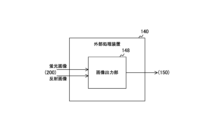
- the image output unit 148 outputs the fluorescence image data and the shadow image data to a display device 150 or the like.
- Each of the functions of the external processing device 140 illustrated in the figure is realized, for example, by a processor (not shown) executing specific software within a personal computer.
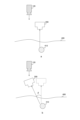
- FIG. 3 is a diagram showing an example of the positions of the imaging device 200 and the excitation light source 120 in the first embodiment of the present technology.
- “a” is a diagram showing an example of the positions of the imaging device 200 and the excitation light source 120 when the image data IMG1 is captured.
- “b” is a diagram showing an example of the positions of the imaging device 200 and the excitation light source 120 when the image data IMG2 is captured.
- the imaging device 200 and the excitation light source 120 are arranged in the endoscope so that the optical axis directions of the imaging device 200 and the excitation light source 120 are aligned.
- the fluorescent material 410 resides in the patient's body and emits light, and the imaging device 200 captures an image of the surface 400 of the organ.
- the user operates the endoscope to change the shooting direction and capture image data IMG2.
- the dotted arrow in b of the same figure indicates the shooting direction of image data IMG1, and the solid arrow indicates the shooting direction of image data IMG2.
- the angle between these shooting directions is ⁇ . This angle can also be described as the angle between the optical axis perpendicular to the image plane on which the image data IMG1 is focused and the optical axis perpendicular to the image plane on which the image data IMG2 is focused.
- a feature point is assumed to occur at a position X1 away from the phosphor 410 in the horizontal direction perpendicular to the shooting direction (i.e., the direction of the dotted arrow). At this time, in the image data IMG2, the feature point occurs at a position X2 away from the phosphor 410.
- FIG. 4 is a diagram showing an example of an input image in the first embodiment of the present technology.
- a is an example of an input image 510 represented by image data IMG1
- b is an example of an input image 520 represented by image data IMG2.
- the angle calculation unit 142 analyzes the image data IMG1 and image data IMG2 to detect multiple feature points. Then, the angle calculation unit 142 calculates the deviation between the feature points in the image data IMG1 and the feature points in the image data IMG2 using an affine transformation or the like, and matches them.
- the distance between a pair of feature points in the image data IMG1 is X1
- the distance between a corresponding pair of feature points in the image data IMG2 is X2 .
- the positional relationship between the imaging device 200 and the excitation light source 120 is not limited to that illustrated in FIG. 3.
- the optical axis direction of the excitation light source 120 can be fixed, and the user can change the shooting direction of the imaging device 200 independently of the excitation light source 120.
- the excitation light source 120 is disposed outside the endoscope 110.
- the imaging device 200 may be disposed at the tip of the endoscope 110, or may be disposed at a location different from the endoscope 110 (such as a tripod).
- a is a diagram showing an example of the positions of the imaging device 200 and the excitation light source 120 when the image data IMG1 is captured.
- b is a diagram showing an example of the positions of the imaging device 200 and the excitation light source 120 when the image data IMG2 is captured.
- FIG. 6 is a diagram showing another example of an input image in the first embodiment of the present technology.
- a is another example of an input image 610 represented by image data IMG1
- b in the figure is another example of an input image 620 represented by image data IMG2.
- input image 610 includes fluorescent region 611 and shaded region 612.
- input image 620 includes fluorescent region 621 and shaded region 622.
- changing the shooting direction changes the position and shape of the subject.
- FIG. 7 is a diagram showing an example of an area in an image in the first embodiment of the present technology.
- a shows an example of processed data 630 generated by assigning labels to areas in an input image 610
- b shows processed data 640 generated by assigning labels to areas in an input image 620.
- the luminance gradient determination unit 143 performs processing such as detecting the edges of objects on the input image 610, and divides the input image 610 into multiple regions. The luminance gradient determination unit 143 then assigns a label to each of the regions. In addition, the luminance gradient determination unit 143 determines, for each region, whether or not the luminance gradient is similar to a specific luminance distribution (such as a Gaussian distribution).
- a specific luminance distribution such as a Gaussian distribution
- the luminance gradient determination unit 143 also divides the input image 620 into multiple regions using edge detection processing or the like, and assigns a label to each region.
- the gray part is the background, and is assigned the label "0", for example.
- the rest of the area is divided into three regions. Each region is assigned the labels "1", “2", and "3", for example.
- the regions with labels "1", “2”, and “3” resemble a specific luminance distribution (such as a Gaussian distribution), and the region with label "0" (such as the background) does not resemble it.
- the luminance gradient determination unit 143 supplies information indicating that the regions with labels "1", “2", and “3” are the regions to be determined, as well as the processing data 630 and 640, to the identical region determination unit 144.
- FIG. 8 is a diagram for explaining the process of determining identical regions in the first embodiment of the present technology.
- a indicates processed data 630 before coordinate conversion corresponding to image data IMG1
- b indicates processed data 631 after coordinate conversion.
- c indicates processed data 640 corresponding to image data IMG2.
- the identical area determination unit 144 transforms each of the coordinates on the boundary of the area into coordinates after rotating them by an angle ⁇ using an affine transformation or the like in the processing data 630 shown in FIG.
- the identical area determination unit 144 determines whether or not there is an identical area in the processed data 640 for each of the areas to be determined in the processed data 631 after the coordinate transformation, depending on whether or not there is an area in the processed data 640 that is similar in shape.
- the regions to be determined for labels "2" and “3” have a shape similar to the regions to be determined for labels “1” and “3” in the processed data 640.
- the identical region determination unit 144 determines that the region to be determined for label "2" in the image data IMG1 is the same as the region to be determined for label "1" in the image data IMG2.
- the identical region determination unit 144 also determines that the region to be determined for label "3" in the image data IMG1 is the same as the region to be determined for label "3" in the image data IMG2.
- the identical region determination unit 144 supplies the determination results and the processed data 630 and 640 to the brightness distribution comparison unit 145.
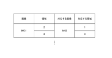
- FIG. 9 is a diagram showing an example of a determination result in the first embodiment of the present technology.
- the determination result includes, for example, information that associates an area labeled "2" in image data IMG1 with an area labeled "1" in image data IMG2 as the same area.
- the determination result also includes information that associates an area labeled "3" in image data IMG1 with an area labeled "3" in image data IMG2 as the same area.
- FIG. 10 is a diagram showing an example of luminance distribution in the first embodiment of the present technology.
- the vertical axis indicates pixel luminance
- the horizontal axis indicates pixel coordinates.
- the dotted line indicates the luminance of the Y coordinate
- the dashed line indicates the luminance of the X coordinate.
- the solid curve indicates the luminance ratio, which is the ratio between the luminance of the Y coordinate and the luminance of the X coordinate.
- a is an example of luminance distribution of the area labeled "2" in image data IMG1
- b is an example of luminance distribution of the area labeled "1" in image data IMG2.
- c is an example of luminance distribution of the area labeled "3" in image data IMG1
- d is an example of luminance distribution of the area labeled "3" in image data IMG2.
- the luminance distribution comparison unit 145 compares the luminance distribution of each of the two regions that have been determined to be the same region. For example, the luminance distribution comparison unit 145 finds the difference in the luminance ratio of each of the two regions for each coordinate, and calculates the sum of these differences.
- the area labeled "2" in image data IMG1 and the area labeled "1" in image data IMG2 have similar luminance distribution shapes, and the total difference in luminance ratios is relatively small.
- the area labeled "3" in image data IMG1 and the area labeled "3" in image data IMG2 have dissimilar luminance distribution shapes, and the total difference in luminance ratios is relatively large.
- the luminance distribution of fluorescent regions changes very little even if the shooting direction is changed.
- the luminance distribution of shaded regions changes significantly when the shooting direction is changed.
- the region labeled "2" in the image data IMG1 corresponding to a in the figure is likely to be a fluorescent region.
- the region labeled "3" in the image data IMG1 corresponding to c in the figure is likely to be a shaded region.
- the luminance distribution comparison unit 145 supplies information indicating whether the total amount of differences for each region exceeds a predetermined judgment threshold as a comparison result to the luminance gradient classification unit 146 together with the processing data 630.
- FIG. 11 is a diagram showing an example of a classification result in the first embodiment of the present technology.
- the luminance gradient classification unit 146 classifies the areas in the image data IMG1 into a plurality of types based on the comparison result of the luminance distribution comparison unit 145 and learning data acquired in advance.
- the accuracy indicating the likelihood is calculated as a numerical value for each type.
- the unit of accuracy is, for example, percent (%).
- the area labeled "1" in image data IMG1 has not been determined by the identical area determination unit 144 to be an identical area in image data IMG2.
- the area labeled "1” is highly likely to be neither a fluorescent area nor a shaded area, and the accuracy value of "other" will be the highest.
- the areas are listed in order of decreasing accuracy.
- the area labeled "2" in the image data IMG1 is determined by the luminance distribution comparison unit 145 to have a total amount of difference in luminance ratios equal to or less than the determination threshold.
- the area labeled "1" is highly likely to be a fluorescent area, and the accuracy value of "fluorescent area" will be the highest.
- the region labeled "3" in the image data IMG1 has been determined by the luminance distribution comparison unit 145 to have a total difference in luminance ratios that exceeds the determination threshold.
- the region labeled "3” is highly likely to be a shadow region, and the precision value for the "shadow region" will be the highest.
- the brightness gradient classification unit 146 supplies the classification results shown in the figure to the image generation unit 147.
- FIG. 12 is a diagram showing an example of an output image in the first embodiment of the present technology.
- a shows an example of a fluorescence image 650
- b shows an example of a shadow image 660.
- the image generating unit 147 extracts areas in the classification results where the "fluorescent area" accuracy is equal to or greater than a predetermined value as fluorescent areas 651 from the image data IMG1, and generates a fluorescent image 650.
- the image generating unit 147 extracts areas that do not correspond to fluorescent areas (such as shaded areas 662) from the image data IMG1 based on the classification results, and generates a shaded image 660.
- the external processing device 140 can determine whether each of the regions is a fluorescent region or a shaded region by comparing the luminance distribution of each region in two images captured in different directions. This prevents the external processing device 140 from erroneously extracting a shaded region as a fluorescent region, improving processing accuracy.
- the image generating unit 147 generates a fluorescent image and a shadow image, but is not limited to this configuration.
- the image generating unit 147 can generate an output image 670 in which fluorescent regions 671 and shaded regions 672 are filled with different colors.
- the image generating unit 147 can generate an output image 680 that highlights the fluorescent region 681, for example by displaying a frame along the contour of the fluorescent region 681.
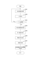
- Example of operation of external processing device is a flowchart showing an example of the operation of the external processing device 140 according to the first embodiment of the present technology. This operation is started, for example, when a predetermined application for imaging is executed.
- the external processing device 140 acquires two images from the imaging device 200 (step S901) and calculates the angle ⁇ between the shooting directions of those images (step S902). The external processing device 140 determines whether ⁇ is greater than a predetermined angle threshold (step S903).
- step S903 the external processing device 140 causes the display device 150 or the like to display a message instructing the user to continue capturing images by changing the capturing angle, and repeats steps S901 and onward.
- step S903 determines whether the luminance gradient of each of a predetermined number of regions in the image data IMG1 resembles a specific luminance distribution (such as a Gaussian distribution).
- the external processing device 140 identifies the region similar to the specific luminance distribution as the region to be determined (step S904).
- the external processing device 140 determines whether each of the target regions in one image is identical to any of the regions in the other image based on the angle ⁇ (step S905). Next, the external processing device 140 compares the luminance distributions of the regions determined to be identical in the two images (step S906).
- the external processing device 140 classifies the regions in the image based on the results of the comparison of the luminance distributions (step S907). Based on the classification results, the external processing device 140 generates and outputs a fluorescent image and a reflected image (step S908). After step S908, the external processing device 140 ends the process for generating a fluorescent image, etc.
- the external processing device 140 compares the luminance distribution of each region in two images captured in different directions, and can therefore determine whether each region is a fluorescent region or a shaded region. This makes it possible to prevent erroneous extraction of a shaded region as a fluorescent region, improving processing accuracy.
- the image processing for generating a fluorescent image, etc. is performed by the external processing device 140, but this is not limiting.
- the image processing system 100 in the first modified example of the first embodiment differs from the first embodiment in that part of the image processing for generating a fluorescent image, etc. is performed by the imaging device 200.
- FIG. 15 is a block diagram showing an example configuration of an imaging device 200 in a first modified example of the first embodiment of the present technology.
- the imaging device 200 in the first modified example of the first embodiment includes a solid-state imaging element 220 and an image processing unit 230.
- the solid-state imaging element 220 generates image data such as image data IMG1 and IMG2, and supplies them to the image processing unit 230.
- the image processing unit 230 includes an image acquisition unit 231, an angle calculation unit 232, a luminance gradient determination unit 233, an identical area determination unit 234, a luminance distribution comparison unit 235, and a luminance gradient classification unit 236. These functions are similar to those of the blocks with the same names in the external processing device 140 in the first embodiment.
- the image processing unit 230 supplies the image data IMG1 and the classification results to the external processing device 140.
- the image processing unit 230 may be, for example, an ISP (Image Signal Processor) or a DSP (Digital Signal Processor).
- ISP Image Signal Processor
- DSP Digital Signal Processor
- each of the above-mentioned functions is implemented in hardware using a FPGA (Field Programmable Gate Array) or the like. This allows the user to rewrite the FPGA and change the output method, etc. according to the use case.
- processing by the image processing unit 230 can also be performed by a signal processing circuit (not shown) within the solid-state imaging element 220.
- FIG. 16 is a block diagram showing an example of the configuration of an external processing device 140 in a first modified example of the first embodiment of the present technology.
- the external processing device 140 in the first modified example of the first embodiment includes an image generating unit 147 and an image output unit 148.
- the imaging device 200 performs part of the image processing (such as comparing luminance distributions) to generate a fluorescent image or the like. This reduces the amount of processing by the external processing device 140.
- the image capture device 200 performs processing such as comparing luminance distributions, thereby reducing the amount of processing by the external processing device 140.
- the imaging device 200 performs part of the image processing for generating a fluorescent image, etc., but this configuration is not limited to this.
- the image processing system 100 in the second modified example of the first embodiment differs from the first modified example of the first embodiment in that the imaging device 200 further performs processing for generating a fluorescent image, etc.
- the imaging device 200 is an example of an image processing device as described in the claims.
- FIG. 17 is a block diagram showing an example configuration of the image processing unit 230 in the second modified example of the first embodiment of the present technology.
- the image processing unit 230 in the second modified example of the first embodiment differs from the first modified example of the first embodiment in that it further includes an image generating unit 237.
- the function of the image generating unit 237 is similar to that of the image generating unit 147 in the first embodiment.
- the image generating unit 237 supplies the generated fluorescent image and reflected image to the external processing device 140.
- FIG. 18 is a block diagram showing an example of the configuration of an external processing device 140 in a second modified example of the first embodiment of the present technology.
- the external processing device 140 in the second modified example of the first embodiment includes an image output unit 148.
- the imaging device 200 further performs processing to generate a fluorescent image, etc. This can further reduce the amount of processing by the external processing device 140.
- the image capturing device 200 further performs processing to generate a fluorescent image, etc., so that the processing load of the external processing device 140 can be further reduced.
- the external processing device 140 calculates the angle between the imaging directions from two images captured by one imaging device 200.
- various calculations such as affine transformation are required to obtain the angle.
- the image processing system 100 in this second embodiment differs from the first embodiment in that two imaging devices are arranged, making angle calculation unnecessary.
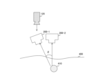
- FIG. 19 is a diagram showing an example of imaging devices 200-1 and 200-2 and an excitation light source 120 in a second embodiment of the present technology.
- the image processing system 100 of this second embodiment differs from the first embodiment in that it includes imaging devices 200-1 and 200-2. These imaging devices are fixed in positions where the angle between their respective shooting directions (in other words, the angle between their optical axes) is ⁇ .
- the position of the excitation light source 120 is arbitrary.
- ⁇ is assumed to be stored in advance in a register or the like within the external processing device 140.
- imaging devices 200-1 and 200-2 are examples of the first imaging device and the second imaging device described in the claims.
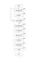
- FIG. 20 is a flowchart showing an example of the operation of the external processing device 140 in the second embodiment of the present technology.
- the operation in this second embodiment differs from the first embodiment in that steps S902 and S903 are not executed.
- ⁇ is known to the external processing device 140, so there is no need to perform step S902 to calculate ⁇ .
- first and second variants of the first embodiment can be applied to the second embodiment.
- the image processing system 100 uses the luminance distribution classification results for fluorescence imaging, but the classification results can also be used for purposes other than fluorescence imaging.
- the imaging device 200 in this third embodiment differs from the first embodiment in that the luminance distribution classification results are used for AF control.
- FIG. 21 is a block diagram showing an example of the configuration of an imaging device 200 according to the third embodiment of the present technology.
- the imaging device 200 includes an optical system 210, a solid-state imaging element 220, an image processing unit 230, a recording unit 250, and an imaging control unit 260.
- the optical system 210 includes a lens group, aperture blades, and actuators that drive them.
- the lens group includes a focus lens group.
- the solid-state imaging element 220 generates image data by photoelectric conversion and supplies it to the image processing unit 230.
- the image processing unit 230 performs predetermined image processing on the image data. This image processing unit 230 supplies the processed image data to the recording unit 250.
- the recording unit 250 records image data.
- the imaging control unit 260 controls the imaging operation of the solid-state imaging element 220.
- the imaging device 200 illustrated in the figure is mounted on a moving object such as a vehicle, and captures multiple image data from different shooting directions while the moving object is moving.
- the user can also capture images by handholding the imaging device 200. In this case, the user captures multiple pieces of image data while changing the shooting direction.
- FIG. 22 is a block diagram showing an example of the configuration of an image processing unit 230 in the third embodiment of the present technology.
- the image processing unit 230 in this third embodiment includes an image acquisition unit 231, an angle calculation unit 232, a luminance gradient determination unit 233, an identical region determination unit 234, a luminance distribution comparison unit 235, and a luminance gradient classification unit 236. These functions are similar to the blocks with the same names in the external processing device 140 in the first embodiment.
- the image processing unit 230 further includes a post-processing unit 240, a region of interest setting unit 241, and an AF control unit 242.
- the post-processing unit 240 performs various image processing such as demosaic processing and white balance processing on the image data IMG1 and IMG2. This post-processing unit 240 supplies the processed image data to the recording unit 250.
- the region of interest setting unit 241 sets a region of interest.
- This region of interest setting unit 241 receives the classification result from the luminance gradient classification unit 236. Then, based on the luminance distribution comparison result and learning data, the luminance gradient classification unit 236 extracts the area of the point light source and classifies it as a light source area. The luminance gradient classification unit 236 also detects the area of shadow caused by the reflection of light from the point light source and classifies it as a shadow area. Based on the classification result, the region of interest setting unit 241 sets the area in the image data IMG1 that does not correspond to the light source area as a region of interest, and supplies setting information indicating the setting content to the AF control unit 242.
- the AF control unit 242 performs AF control to focus on a subject within the region of interest. For example, the AF control unit 242 determines the position where the subject is in focus using a phase difference method or a contrast method, and moves the focus lens group within the optical system 210 according to that position.
- FIG. 23 is a diagram showing an example of an input image in the third embodiment of the present technology.
- a is an example of an input image 710 represented by image data IMG1
- b is an example of an input image 720 represented by image data IMG2.
- Input image 710 includes objects such as a building 711, a person 712, and a point light source 713, while input image 720 includes a building 721, a person 722, and a point light source 723.
- the luminance distribution of a point light source is spatially isotropic, with the center being bright and the further away it is, the darker the distribution is, and has characteristics similar to those of a fluorescent region. Therefore, by using processing similar to that of the first embodiment to detect the light source region and perform AF control while avoiding that region, the accuracy of AF control can be improved.
- FIG. 24 is a flowchart showing an example of the operation of the image processing unit 230 in the third embodiment of the present technology.
- the operation in this third embodiment differs from the operation shown in FIG. 14 in that steps S910 to S912 are executed instead of steps S907 and S908.
- the image processing unit 230 extracts the area of the point light source based on the result of the comparison of the luminance distribution and the learning data, and classifies it as a light source area (step S910). Then, based on the classification result, the image processing unit 230 sets the area in the image data IMG1 that does not correspond to the light source area as a region of interest (step S911), and performs AF control to focus on the subject in the region of interest (step S912).
- the imaging device 200 sets and focuses on a region of interest based on the analysis results of the luminance distribution, thereby improving AF accuracy.
- the classification result of the luminance distribution is used for AF control, but the classification result can be used for purposes other than AF control.
- the imaging device 200 in the first modification of the third embodiment differs from the third embodiment in that the classification result of the luminance distribution is used for exposure control.
- FIG. 25 is a block diagram showing an example of the configuration of the image processing unit 230 in a first modified example of the third embodiment of the present technology.
- the image processing unit 230 in the first modified example of the third embodiment differs from the third embodiment in that it includes a photometry unit 243 and an exposure control unit 244 instead of a region of interest setting unit 241 and an AF control unit 242.
- the photometry unit 243 receives the classification result from the brightness gradient classification unit 236. Then, the photometry unit 243 sets a photometry area in the image data IMG1 based on the classification result and measures the amount of light in that area. For example, an area other than the light source area is set as the photometry area. The photometry unit 243 supplies the photometry amount to the exposure control unit 244.
- the exposure control unit 244 controls the amount of exposure based on the amount of light measured. For example, the exposure control unit 244 controls the aperture value of the optical system 210 and the exposure time and sensitivity of the solid-state imaging element 220.
- the imaging device 200 By having the imaging device 200 measure light while avoiding the light source area, it is possible to prevent the image capture device 200 from measuring light in an area that includes the light source area, and to control the amount of exposure to an appropriate value.
- the imaging device 200 uses the luminance distribution classification results only for exposure control, this is not limited to the configuration.
- the imaging device 200 can also use the classification results for both AF control and exposure control.
- the imaging device 200 performs photometry while avoiding the light source area based on the analysis results of the luminance distribution, and therefore can control the exposure amount to an appropriate value.
- the classification result of the luminance distribution is used for AF control, but the classification result can be used for purposes other than AF control.
- the imaging device 200 in the second modification of the third embodiment differs from the third embodiment in that the classification result of the luminance distribution is used for AWB control.
- FIG. 26 is a block diagram showing an example of the configuration of the image processing unit 230 in a second modified example of the third embodiment of the present technology.
- the image processing unit 230 in the second modified example of the third embodiment differs from the third embodiment in that it includes an AWB control unit 245 instead of the region of interest setting unit 241 and the AF control unit 242.
- the AWB control unit 245 receives the classification result from the luminance gradient classification unit 236. The AWB control unit 245 then extracts the light source area in the image data IMG1 based on the classification result and estimates the light source. The AWB control unit 245 then adjusts the white balance of the image data IMG1 to match the estimated light source, and supplies the adjusted image data to the post-processing unit 240.
- the post-processing unit 240 performs various types of processing on the image data other than white balance processing.
- the imaging device 200 estimates the light source from the area classified as a light source area by the luminance gradient classification unit 236, thereby improving the accuracy of estimating the light source and adjusting the white balance to an appropriate value.
- the image capture device 200 uses the luminance distribution classification results only for AWB control, this configuration is not limited.
- the image capture device 200 can use the classification results for at least one of AF control, exposure control, and AWB control.
- the imaging device 200 estimates the light source based on the classification result, and therefore can adjust the white balance to an appropriate value.
- the technology according to the present disclosure (the present technology) can be applied to various products.
- the technology according to the present disclosure may be applied to an endoscopic surgery system.
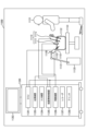
- FIG. 27 is a diagram showing an example of the general configuration of an endoscopic surgery system to which the technology disclosed herein (the present technology) can be applied.
- an operator (doctor) 11131 is shown using an endoscopic surgery system 11000 to perform surgery on a patient 11132 on a patient bed 11133.
- the endoscopic surgery system 11000 is composed of an endoscope 11100, other surgical tools 11110 such as an insufflation tube 11111 and an energy treatment tool 11112, a support arm device 11120 that supports the endoscope 11100, and a cart 11200 on which various devices for endoscopic surgery are mounted.
- the endoscope 11100 is composed of a lens barrel 11101, the tip of which is inserted into the body cavity of the patient 11132 at a predetermined length, and a camera head 11102 connected to the base end of the lens barrel 11101.
- the endoscope 11100 is configured as a so-called rigid scope having a rigid lens barrel 11101, but the endoscope 11100 may also be configured as a so-called flexible scope having a flexible lens barrel.
- the tip of the tube 11101 has an opening into which an objective lens is fitted.
- a light source device 11203 is connected to the endoscope 11100, and light generated by the light source device 11203 is guided to the tip of the tube by a light guide extending inside the tube 11101, and is irradiated via the objective lens towards an object to be observed inside the body cavity of the patient 11132.
- the endoscope 11100 may be a direct-viewing endoscope, an oblique-viewing endoscope, or a side-viewing endoscope.
- An optical system and an image sensor are provided inside the camera head 11102, and reflected light (observation light) from the object being observed is focused onto the image sensor by the optical system.
- the image sensor converts the observation light into an electric signal corresponding to the observation light, i.e., an image signal corresponding to the observed image.
- the image signal is sent to the camera control unit (CCU: Camera Control Unit) 11201 as RAW data.
- CCU Camera Control Unit
- the CCU 11201 is composed of a CPU (Central Processing Unit), a GPU (Graphics Processing Unit), etc., and controls the overall operation of the endoscope 11100 and the display device 11202. Furthermore, the CCU 11201 receives an image signal from the camera head 11102, and performs various types of image processing on the image signal, such as development processing (demosaic processing), in order to display an image based on the image signal.
- a CPU Central Processing Unit
- GPU Graphics Processing Unit
- the display device 11202 under the control of the CCU 11201, displays an image based on the image signal that has been subjected to image processing by the CCU 11201.
- the light source device 11203 is composed of a light source such as an LED (light emitting diode) and supplies illumination light to the endoscope 11100 when photographing the surgical site, etc.
- a light source such as an LED (light emitting diode)
- the input device 11204 is an input interface for the endoscopic surgery system 11000.
- a user can input various information and instructions to the endoscopic surgery system 11000 via the input device 11204.
- the user inputs an instruction to change the imaging conditions (type of irradiation light, magnification, focal length, etc.) of the endoscope 11100.
- the treatment tool control device 11205 controls the operation of the energy treatment tool 11112 for cauterizing tissue, incising, sealing blood vessels, etc.
- the insufflation device 11206 sends gas into the body cavity of the patient 11132 via the insufflation tube 11111 to inflate the body cavity in order to ensure a clear field of view for the endoscope 11100 and to ensure a working space for the surgeon.
- the recorder 11207 is a device capable of recording various types of information related to the surgery.
- the printer 11208 is a device capable of printing various types of information related to the surgery in various formats such as text, images, or graphs.
- the light source device 11203 that supplies irradiation light to the endoscope 11100 when photographing the surgical site can be composed of a white light source composed of, for example, an LED, a laser light source, or a combination of these.
- a white light source composed of, for example, an LED, a laser light source, or a combination of these.
- the white light source is composed of a combination of RGB laser light sources, the output intensity and output timing of each color (each wavelength) can be controlled with high precision, so that the white balance of the captured image can be adjusted in the light source device 11203.
- the light source device 11203 may be controlled to change the intensity of the light it outputs at predetermined time intervals.
- the image sensor of the camera head 11102 may be controlled to acquire images in a time-division manner in synchronization with the timing of the change in the light intensity, and the images may be synthesized to generate an image with a high dynamic range that is free of so-called blackout and whiteout.
- the light source device 11203 may be configured to supply light of a predetermined wavelength band corresponding to special light observation.
- special light observation for example, by utilizing the wavelength dependency of light absorption in body tissue, a narrow band of light is irradiated compared to the light irradiated during normal observation (i.e., white light), and a specific tissue such as blood vessels on the surface of the mucosa is photographed with high contrast, so-called narrow band imaging is performed.
- fluorescence observation may be performed in which an image is obtained by fluorescence generated by irradiating excitation light.
- excitation light is irradiated to body tissue and fluorescence from the body tissue is observed (autofluorescence observation), or a reagent such as indocyanine green (ICG) is locally injected into the body tissue and excitation light corresponding to the fluorescence wavelength of the reagent is irradiated to the body tissue to obtain a fluorescent image.
- the light source device 11203 may be configured to supply narrow band light and/or excitation light corresponding to such special light observation.
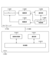
- FIG. 28 is a block diagram showing an example of the functional configuration of the camera head 11102 and CCU 11201 shown in FIG. 27.
- the camera head 11102 has a lens unit 11401, an imaging unit 11402, a drive unit 11403, a communication unit 11404, and a camera head control unit 11405.
- the CCU 11201 has a communication unit 11411, an image processing unit 11412, and a control unit 11413.
- the camera head 11102 and the CCU 11201 are connected to each other via a transmission cable 11400 so that they can communicate with each other.
- the lens unit 11401 is an optical system provided at the connection with the lens barrel 11101. Observation light taken in from the tip of the lens barrel 11101 is guided to the camera head 11102 and enters the lens unit 11401.
- the lens unit 11401 is composed of a combination of multiple lenses including a zoom lens and a focus lens.
- the imaging unit 11402 may include one imaging element (a so-called single-plate type) or multiple imaging elements (a so-called multi-plate type).
- each imaging element may generate an image signal corresponding to each of RGB, and a color image may be obtained by combining these.
- the imaging unit 11402 may be configured to have a pair of imaging elements for acquiring image signals for the right eye and the left eye corresponding to a 3D (dimensional) display. By performing a 3D display, the surgeon 11131 can more accurately grasp the depth of the biological tissue in the surgical site.
- multiple lens units 11401 may be provided corresponding to each imaging element.
- the imaging unit 11402 does not necessarily have to be provided in the camera head 11102.
- the imaging unit 11402 may be provided inside the lens barrel 11101, immediately after the objective lens.
- the driving unit 11403 is composed of an actuator, and moves the zoom lens and focus lens of the lens unit 11401 a predetermined distance along the optical axis under the control of the camera head control unit 11405. This allows the magnification and focus of the image captured by the imaging unit 11402 to be adjusted appropriately.
- the communication unit 11404 is configured with a communication device for transmitting and receiving various information to and from the CCU 11201.
- the communication unit 11404 transmits the image signal obtained from the imaging unit 11402 as RAW data to the CCU 11201 via the transmission cable 11400.
- the communication unit 11404 also receives control signals for controlling the operation of the camera head 11102 from the CCU 11201, and supplies them to the camera head control unit 11405.
- the control signals include information on the imaging conditions, such as information specifying the frame rate of the captured image, information specifying the exposure value during imaging, and/or information specifying the magnification and focus of the captured image.
- the above-mentioned frame rate, exposure value, magnification, focus, and other imaging conditions may be appropriately specified by the user, or may be automatically set by the control unit 11413 of the CCU 11201 based on the acquired image signal.
- the endoscope 11100 is equipped with the so-called AE (Auto Exposure) function, AF (Auto Focus) function, and AWB (Auto White Balance) function.
- the camera head control unit 11405 controls the operation of the camera head 11102 based on a control signal from the CCU 11201 received via the communication unit 11404.
- the communication unit 11411 is configured with a communication device for transmitting and receiving various information to and from the camera head 11102.
- the communication unit 11411 receives an image signal transmitted from the camera head 11102 via the transmission cable 11400.
- the communication unit 11411 also transmits to the camera head 11102 a control signal for controlling the operation of the camera head 11102.
- the image signal and the control signal can be transmitted by electrical communication, optical communication, etc.
- the image processing unit 11412 performs various image processing operations on the image signal, which is the RAW data transmitted from the camera head 11102.
- the control unit 11413 performs various controls related to the imaging of the surgical site, etc. by the endoscope 11100, and the display of the captured images obtained by imaging the surgical site, etc. For example, the control unit 11413 generates a control signal for controlling the driving of the camera head 11102.
- the control unit 11413 also causes the display device 11202 to display the captured image showing the surgical site, etc., based on the image signal that has been image-processed by the image processing unit 11412. At this time, the control unit 11413 may recognize various objects in the captured image using various image recognition techniques. For example, the control unit 11413 can recognize surgical tools such as forceps, specific body parts, bleeding, mist generated when the energy treatment tool 11112 is used, etc., by detecting the shape and color of the edges of objects included in the captured image. When the control unit 11413 causes the display device 11202 to display the captured image, it may use the recognition result to superimpose various types of surgical support information on the image of the surgical site. By superimposing the surgical support information and presenting it to the surgeon 11131, the burden on the surgeon 11131 can be reduced and the surgeon 11131 can proceed with the surgery reliably.
- various image recognition techniques such as forceps, specific body parts, bleeding, mist generated when the energy treatment tool 11112 is used, etc.
- the transmission cable 11400 that connects the camera head 11102 and the CCU 11201 is an electrical signal cable that supports electrical signal communication, an optical fiber that supports optical communication, or a composite cable of these.
- communication is performed wired using a transmission cable 11400, but communication between the camera head 11102 and the CCU 11201 may also be performed wirelessly.
- the technology according to the present disclosure can be applied to various products.
- the technology according to the present disclosure may be realized as a device mounted on any type of moving body such as an automobile, an electric vehicle, a hybrid electric vehicle, a motorcycle, a bicycle, a personal mobility device, an airplane, a drone, a ship, or a robot.
- FIG. 29 is a block diagram showing a schematic configuration example of a vehicle control system, which is an example of a mobile object control system to which the technology disclosed herein can be applied.
- the vehicle control system 12000 includes a plurality of electronic control units connected via a communication network 12001.
- the vehicle control system 12000 includes a drive system control unit 12010, a body system control unit 12020, an outside vehicle information detection unit 12030, an inside vehicle information detection unit 12040, and an integrated control unit 12050.
- Also shown as functional components of the integrated control unit 12050 are a microcomputer 12051, an audio/video output unit 12052, and an in-vehicle network I/F (interface) 12053.
- the drive system control unit 12010 controls the operation of devices related to the drive system of the vehicle according to various programs.
- the drive system control unit 12010 functions as a control device for a drive force generating device for generating the drive force of the vehicle, such as an internal combustion engine or a drive motor, a drive force transmission mechanism for transmitting the drive force to the wheels, a steering mechanism for adjusting the steering angle of the vehicle, and a braking device for generating a braking force for the vehicle.
- the body system control unit 12020 controls the operation of various devices installed in the vehicle body according to various programs.
- the body system control unit 12020 functions as a control device for a keyless entry system, a smart key system, a power window device, or various lamps such as headlamps, tail lamps, brake lamps, turn signals, and fog lamps.
- radio waves or signals from various switches transmitted from a portable device that replaces a key can be input to the body system control unit 12020.
- the body system control unit 12020 accepts the input of these radio waves or signals and controls the vehicle's door lock device, power window device, lamps, etc.
- the outside-vehicle information detection unit 12030 detects information outside the vehicle equipped with the vehicle control system 12000.
- the image capturing unit 12031 is connected to the outside-vehicle information detection unit 12030.
- the outside-vehicle information detection unit 12030 causes the image capturing unit 12031 to capture images outside the vehicle and receives the captured images.
- the outside-vehicle information detection unit 12030 may perform object detection processing or distance detection processing for people, cars, obstacles, signs, characters on the road surface, etc. based on the received images.
- the imaging unit 12031 is an optical sensor that receives light and outputs an electrical signal according to the amount of light received.
- the imaging unit 12031 can output the electrical signal as an image, or as distance measurement information.
- the light received by the imaging unit 12031 may be visible light, or may be invisible light such as infrared light.
- the in-vehicle information detection unit 12040 detects information inside the vehicle.
- a driver state detection unit 12041 that detects the state of the driver is connected.
- the driver state detection unit 12041 includes, for example, a camera that captures an image of the driver, and the in-vehicle information detection unit 12040 may calculate the driver's degree of fatigue or concentration based on the detection information input from the driver state detection unit 12041, or may determine whether the driver is dozing off.
- the microcomputer 12051 can calculate control target values for the driving force generating device, steering mechanism, or braking device based on information inside and outside the vehicle acquired by the outside-vehicle information detection unit 12030 or the inside-vehicle information detection unit 12040, and output control commands to the drive system control unit 12010.
- the microcomputer 12051 can perform cooperative control aimed at realizing the functions of an Advanced Driver Assistance System (ADAS), including vehicle collision avoidance or impact mitigation, following driving based on the distance between vehicles, maintaining vehicle speed, vehicle collision warning, or vehicle lane departure warning.
- ADAS Advanced Driver Assistance System
- the microcomputer 12051 can also perform cooperative control for the purpose of autonomous driving, which allows the vehicle to travel autonomously without relying on the driver's operation, by controlling the driving force generating device, steering mechanism, braking device, etc. based on information about the surroundings of the vehicle acquired by the outside vehicle information detection unit 12030 or the inside vehicle information detection unit 12040.
- the microcomputer 12051 can also output control commands to the body system control unit 12020 based on information outside the vehicle acquired by the outside information detection unit 12030. For example, the microcomputer 12051 can control the headlamps according to the position of a preceding vehicle or an oncoming vehicle detected by the outside information detection unit 12030, and perform cooperative control aimed at preventing glare, such as switching from high beams to low beams.
- the audio/image output unit 12052 transmits at least one output signal of audio and image to an output device capable of visually or audibly notifying the occupants of the vehicle or the outside of the vehicle of information.
- an audio speaker 12061, a display unit 12062, and an instrument panel 12063 are exemplified as output devices.
- the display unit 12062 may include, for example, at least one of an on-board display and a head-up display.
- FIG. 30 shows an example of the installation position of the imaging unit 12031.
- the imaging unit 12031 includes imaging units 12101, 12102, 12103, 12104, and 12105.
- the imaging units 12101, 12102, 12103, 12104, and 12105 are provided, for example, at the front nose, side mirrors, rear bumper, back door, and upper part of the windshield inside the vehicle cabin of the vehicle 12100.
- the imaging unit 12101 provided at the front nose and the imaging unit 12105 provided at the upper part of the windshield inside the vehicle cabin mainly acquire images of the front of the vehicle 12100.
- the imaging units 12102 and 12103 provided at the side mirrors mainly acquire images of the sides of the vehicle 12100.
- the imaging unit 12104 provided at the rear bumper or back door mainly acquires images of the rear of the vehicle 12100.
- the imaging unit 12105 provided at the upper part of the windshield inside the vehicle cabin is mainly used to detect leading vehicles, pedestrians, obstacles, traffic lights, traffic signs, lanes, etc.
- FIG. 30 shows an example of the imaging ranges of the imaging units 12101 to 12104.
- Imaging range 12111 indicates the imaging range of the imaging unit 12101 provided on the front nose
- imaging ranges 12112 and 12113 indicate the imaging ranges of the imaging units 12102 and 12103 provided on the side mirrors, respectively
- imaging range 12114 indicates the imaging range of the imaging unit 12104 provided on the rear bumper or back door.
- an overhead image of the vehicle 12100 viewed from above is obtained by superimposing the image data captured by the imaging units 12101 to 12104.
- At least one of the imaging units 12101 to 12104 may have a function of acquiring distance information.
- at least one of the imaging units 12101 to 12104 may be a stereo camera consisting of multiple imaging elements, or an imaging element having pixels for phase difference detection.
- the microcomputer 12051 can obtain the distance to each solid object within the imaging ranges 12111 to 12114 and the change in this distance over time (relative speed with respect to the vehicle 12100) based on the distance information obtained from the imaging units 12101 to 12104, and can extract as a preceding vehicle, in particular, the closest solid object on the path of the vehicle 12100 that is traveling in approximately the same direction as the vehicle 12100 at a predetermined speed (e.g., 0 km/h or faster). Furthermore, the microcomputer 12051 can set the inter-vehicle distance that should be maintained in advance in front of the preceding vehicle, and perform automatic braking control (including follow-up stop control) and automatic acceleration control (including follow-up start control). In this way, cooperative control can be performed for the purpose of automatic driving, which runs autonomously without relying on the driver's operation.
- automatic braking control including follow-up stop control
- automatic acceleration control including follow-up start control
- the microcomputer 12051 classifies and extracts three-dimensional object data on three-dimensional objects, such as two-wheeled vehicles, ordinary vehicles, large vehicles, pedestrians, utility poles, and other three-dimensional objects, based on the distance information obtained from the imaging units 12101 to 12104, and can use the data to automatically avoid obstacles.
- the microcomputer 12051 distinguishes obstacles around the vehicle 12100 into obstacles that are visible to the driver of the vehicle 12100 and obstacles that are difficult to see.
- the microcomputer 12051 determines the collision risk, which indicates the risk of collision with each obstacle, and when the collision risk is equal to or exceeds a set value and there is a possibility of a collision, it can provide driving assistance for collision avoidance by outputting an alarm to the driver via the audio speaker 12061 or the display unit 12062, or by performing forced deceleration or avoidance steering via the drive system control unit 12010.
- At least one of the imaging units 12101 to 12104 may be an infrared camera that detects infrared rays.
- the microcomputer 12051 can recognize a pedestrian by determining whether or not a pedestrian is present in the image captured by the imaging units 12101 to 12104. The recognition of such a pedestrian is performed, for example, by a procedure of extracting feature points in the image captured by the imaging units 12101 to 12104 as infrared cameras, and a procedure of performing pattern matching processing on a series of feature points that indicate the contour of an object to determine whether or not it is a pedestrian.
- the audio/image output unit 12052 controls the display unit 12062 to superimpose a rectangular contour line for emphasis on the recognized pedestrian.
- the audio/image output unit 12052 may also control the display unit 12062 to display an icon or the like indicating a pedestrian at a desired position.
- the technology disclosed herein can be applied to, for example, the imaging unit 12031.
- the imaging device 200 in FIG. 21 can be applied to the imaging unit 12031.
- the processing procedures described in the above embodiments may be regarded as a method having a series of these procedures, or as a program for causing a computer to execute the series of procedures, or as a recording medium for storing the program.
- a CD Compact Disc
- MD Mini Disc
- DVD Digital Versatile Disc
- a memory card a Blu-ray (registered trademark) Disc, etc.
- Blu-ray registered trademark
- An image processing device including a brightness distribution comparison unit that compares a brightness distribution of a first region in a first image with a brightness distribution of a second region in a second image, the first image and the second image being generated by photographing from a first direction and a second direction that are different from each other.
- the image processing device described in (1) further includes an identical area determination unit that determines whether each of a predetermined number of determination target areas in the first image is identical to any of the areas in the second image based on the angle between the first direction and the second direction, and supplies the identical areas to the brightness distribution comparison unit as the first area and the second area.
- the image processing device further comprising an angle calculation unit that calculates the angle between the first direction and the second direction based on the first image and the second image and supplies the angle to the identical area determination unit.
- the image processing device described in (2) or (3) further comprising a brightness gradient determination unit that supplies a region in the first image that resembles a specific brightness distribution as the determination target region to the identical region determination unit.
- the image processing device according to any one of (1) to (4), further comprising a luminance gradient classification unit that classifies regions in the first image based on a comparison result of the luminance distribution comparison unit.
- a region of interest setting unit that sets a region of interest in the first image based on a classification result of the luminance gradient classification unit;
- the image processing device further comprising an AF control unit that performs processing for focusing on a subject within the region of interest.
- a photometry unit that sets a photometry area in the first image based on a classification result of the luminance gradient classification unit and measures a light amount of the photometry area;
- the image processing device according to (5) or (6), further comprising an exposure control unit that controls an amount of exposure based on the measured amount of light.
- the image processing device according to any one of (5) to (7), further comprising an AWB (Auto White Balance) control unit that adjusts the white balance of the first image based on the classification result of the luminance gradient classification unit.
- the image processing device according to any one of (5) to (8), further comprising an image generating unit that generates an image based on a classification result of the luminance gradient classifying unit.
- the image processing device according to (9), wherein the image generating unit generates a fluorescent image by extracting a fluorescent region from the first image and a reflected image by extracting a region not corresponding to the fluorescent region from the first image.
- the image processing system further comprising an imaging device that captures the first image and the second image in sequence.
- a first imaging device that captures the first image from the first direction;
- An imaging device including a luminance distribution comparison unit that compares a luminance distribution of a first region in a first image with a luminance distribution of a second region in a second image, the first image and the second image being generated by photographing the first image and the second image from different directions; and an external processing device that processes an image based on output data from the imaging device.
- An image processing method including a luminance distribution comparison step of comparing a luminance distribution of a first region in a first image with a luminance distribution of a second region in a second image, the first image and the second image being generated by photographing from a first direction and a second direction that are different from each other.
- Image processing system 110 Endoscope 120 Excitation light source 130 Control device 140 External processing device 141, 231 Image acquisition unit 142, 232 Angle calculation unit 143, 233 Brightness gradient determination unit 144, 234 Identical area determination unit 145, 235 Brightness distribution comparison unit 146, 236 Brightness gradient classification unit 147, 237 Image generation unit 148 Image output unit 150 Display device 200, 200-1, 200-2 Imaging device 210 Optical system 220 Solid-state imaging element 230, 11412 Image processing unit 240 Post-processing unit 241 Region of interest setting unit 242 AF control unit 243 Photometry unit 244 Exposure control unit 245 AWB processing unit 250 Recording unit 260 Imaging control unit 12031 Imaging unit
Landscapes
- Engineering & Computer Science (AREA)
- Multimedia (AREA)
- Signal Processing (AREA)
- Human Computer Interaction (AREA)
- Physics & Mathematics (AREA)
- General Physics & Mathematics (AREA)
- Theoretical Computer Science (AREA)
- Image Processing (AREA)
Abstract
光源領域を抽出する画像処理装置において、処理精度を向上させる。 画像処理装置は、輝度分布比較部を具備する。この画像処理装置において、輝度分布比較部は、第1領域の輝度分布と第2領域の輝度分布とを比較する。ここで、第1領域は、第1画像内の領域である。また、第2領域は、第2画像内の領域である。また、第1画像および第2画像は、第1方向および第2方向からの撮影により生成された画像である。第1方向および第2方向は、互いに異なる方向である。
Description
本技術は、画像処理装置に関する。詳しくは、複数の画像を処理する画像処理装置、画像処理システム、画像処理方法、および、当該方法をコンピュータに実行させるためのプログラムに関する。
従来より、輝度分布を用いる画像処理が様々な分野で利用されている。例えば、光源領域の輝度分布がガウス分布状であると仮定し、ガウス分布から作成したテンプレートと画像内の輝度分布とのマッチングを行う装置が提案されている(例えば、特許文献1参照。)。この装置では、マッチングにより輝度分布がガウス分布と類似する領域が、光源領域として抽出される。
上述の従来技術では、ガウス分布から作成したテンプレートと画像内の輝度分布とのマッチングにより、光源領域の抽出を図っている。しかしながら、上述の装置では、光源からの光が反射して生じた陰影の領域も、輝度分布がガウス分布と類似することがあるため、その領域を誤って光源領域として抽出するおそれがある。この結果、光源領域を抽出する処理の精度が低下してしまうという問題がある。
本技術はこのような状況に鑑みて生み出されたものであり、光源領域を抽出する画像処理装置において、処理精度を向上させることを目的とする。
本技術は、上述の問題点を解消するためになされたものであり、その第1の側面は、互いに異なる第1方向および第2方向からの撮影により生成された第1画像および第2画像のうち上記第1画像内の第1領域の輝度分布と上記第2画像内の第2領域の輝度分布とを比較する輝度分布比較部を具備する画像処理装置、および、当該装置の画像処理方法、並びに、当該方法をコンピュータに実行させるためのプログラムである。これにより、処理精度が向上するという作用をもたらす。
また、この第1の側面において、上記第1方向と上記第2方向とのなす角度に基づいて上記第1画像内の所定数の判定対象領域のそれぞれについて上記第2画像内の領域のいずれかと同一であるか否かを判定して同一の領域を上記第1領域および上記第2領域として上記輝度分布比較部に供給する同一領域判定部をさらに具備してもよい。これにより、同一領域の輝度分布が比較されるという作用をもたらす。
また、この第1の側面において、上記第1画像および上記第2画像に基づいて上記第1方向と上記第2方向とのなす角度を算出して上記同一領域判定部に供給する角度算出部をさらに具備してもよい。これにより、1台の撮像装置の撮像した画像から角度が算出されるという作用をもたらす。
また、この第1の側面において、上記第1画像内の領域のうち特定の輝度分布に類似する領域を上記判定対象領域として上記同一領域判定部に供給する輝度勾配判定部をさらに具備してもよい。これにより、特定の輝度分布の領域が同一領域判定部で判定されるという作用をもたらす。
また、この第1の側面において、上記輝度分布比較部の比較結果に基づいて上記第1画像内の領域を分類する輝度勾配分類部をさらに具備してもよい。これにより、領域が適切に分類されるという作用をもたらす。
また、この第1の側面において、上記輝度勾配分類部の分類結果に基づいて上記第1画像内に関心領域を設定する関心領域設定部と、上記関心領域内の被写体に焦点を合わせる処理を行うAF(Auto Focus)制御部とをさらに具備してもよい。これにより、合焦精度が向上するという作用をもたらす。
また、この第1の側面において、上記輝度勾配分類部の分類結果に基づいて上記第1画像内に測光領域を設定して上記測光領域の光量を測定する測光部と、上記測定された光量に基づいて露光量を制御する露光制御部とをさらに具備してもよい。これにより、露光量が適切な値に制御されるという作用をもたらす。
また、この第1の側面において、上記輝度勾配分類部の分類結果に基づいて上記第1画像のホワイトバランスを調整するAWB(Auto White Balance)制御部をさらに具備してもよい。これにより、ホワイトバランスが適切な値に調整されるという作用をもたらす。
また、この第1の側面において、輝度勾配分類部の分類結果に基づいて画像を生成する画像生成部をさらに具備してもよい。これにより、蛍光画像などが生成されるという作用をもたらす。
また、この第1の側面において、前記画像生成部は、前記第1画像から蛍光領域を抽出した蛍光画像と前記第1画像から前記蛍光領域に該当しない領域を抽出した反射画像とを生成してもよい。これにより、蛍光画像および陰影画像を区別しやすくなるという作用をもたらす。
また、この第1の側面において、前記画像生成部は、前記第1画像内の蛍光領域と陰影領域とを異なる色で塗りつぶした画像を生成してもよい。これにより、蛍光画像および陰影画像を区別しやすくなるという作用をもたらす。
また、この第1の側面において、前記画像生成部は、前記第1画像内の蛍光領域を強調表示した画像を生成してもよい。これにより、蛍光画像および陰影画像を区別しやすくなるという作用をもたらす。
また、本技術の第2の側面は、励起光源と、互いに異なる第1方向および第2方向からの撮影により生成された第1画像および第2画像のうち上記第1画像内の第1領域の輝度分布と上記第2画像内の第2領域の輝度分布とを比較する輝度分布比較部を具備する外部処理装置とを具備する画像処理システムである。これにより、画像処理システムの処理精度が向上するという作用をもたらす。
また、この第2の側面において、上記第1画像および上記第2画像を順に撮像する撮像装置をさらに具備してもよい。これにより、1台の撮像装置の撮像した画像から角度が算出されるという作用をもたらす。
また、この第2の側面において、上記第1方向から上記第1画像を撮像する第1撮像装置と、上記第2方向から上記第2画像を撮像する第2撮像装置とをさらに具備してもよい。これにより、角度の算出が不要になるという作用をもたらす。
また、本技術の第3の側面は、互いに異なる第1方向および第2方向からの撮影により生成された第1画像および第2画像のうち上記第1画像内の第1領域の輝度分布と上記第2画像内の第2領域の輝度分布とを比較する輝度分布比較部を具備する撮像装置と、上記撮像装置の出力データに基づいて画像を処理する外部処理装置とを具備する画像処理システムである。これにより、画像処理システムの処理精度が向上するという作用をもたらす。
以下、本技術を実施するための形態(以下、実施の形態と称する)について説明する。説明は以下の順序により行う。
1.第1の実施の形態(輝度分布を比較する例)
2.第2の実施の形態(撮像装置を2台にし、輝度分布を比較する例)
3.第3の実施の形態(輝度分布を比較し、焦点を合わせる例)
4.内視鏡手術システムへの応用例
5.移動体への応用例
1.第1の実施の形態(輝度分布を比較する例)
2.第2の実施の形態(撮像装置を2台にし、輝度分布を比較する例)
3.第3の実施の形態(輝度分布を比較し、焦点を合わせる例)
4.内視鏡手術システムへの応用例
5.移動体への応用例
<1.第1の実施の形態>
[内視鏡手術システムの構成例]
図1は、本技術の実施の形態における画像処理システム100の一構成例を示すブロック図である。この画像処理システム100は、内視鏡による手術や検査に用いられるシステムであり、内視鏡110、制御装置130、外部処理装置140および表示装置150を備える。
[内視鏡手術システムの構成例]
図1は、本技術の実施の形態における画像処理システム100の一構成例を示すブロック図である。この画像処理システム100は、内視鏡による手術や検査に用いられるシステムであり、内視鏡110、制御装置130、外部処理装置140および表示装置150を備える。
内視鏡110は、先端から所定の長さの領域が患者の体腔内に挿入される鏡筒(不図示)と、鏡筒の基端に接続される撮像装置200と、励起光源120とから構成される。
励起光源120は、蛍光体(蛍光試薬や蛍光抗体など)を発光させるための特定の波長の光を励起光として照射するものである。励起光源120として、水銀アークやタングステンハロゲンランプ等の広帯域光源、あるいは、レーザー励起源やLED(Light-Emitting Diode)が用いられる。
撮像装置200は、光電変換により画像を撮像するものである。この撮像装置200は、光学系や固体撮像素子を備え、画像データを生成して外部処理装置140に送信する。
制御装置130は、内視鏡110、外部処理装置140や表示装置150などの画像処理システム100内の機器や装置を制御するものである。
外部処理装置140は、撮像装置200からの画像データに対して各種の画像処理を行うものである。この外部処理装置140は、処理後の画像データを表示装置150に表示させる。外部処理装置140として、パーソナルコンピュータなどが用いられる。なお、外部処理装置140は、特許請求の範囲に記載の画像処理装置の一例である。
ここで、ユーザは、内視鏡による手術や検査の際に蛍光イメージングを用いることができる。この蛍光イメージングでは、体内の特定の領域(腫瘍領域など)に滞留する蛍光物質が患者に投与され、その領域が標識される。そして、励起光源120は、制御装置130の制御に従って励起光を照射し、その励起光と波長の異なる蛍光を標識された領域に生じさせる。この蛍光を発する領域を以下、「蛍光領域」と称する。体内を通りやすいように、蛍光として、近赤外光や赤外光が利用される。撮像装置200は、ユーザの操作に従って蛍光領域を複数回に亘って撮像する。この際にユーザは、内視鏡110を操作して、少なくとも2枚の画像のそれぞれを異なる方向から撮像させる。
[外部処理装置の構成例]
図2は、本技術の第1の実施の形態における外部処理装置140の一構成例を示すブロック図である。この外部処理装置140は、画像取得部141、角度算出部142、輝度勾配判定部143、同一領域判定部144、輝度分布比較部145、輝度勾配分類部146、画像生成部147および画像出力部148を備える。
図2は、本技術の第1の実施の形態における外部処理装置140の一構成例を示すブロック図である。この外部処理装置140は、画像取得部141、角度算出部142、輝度勾配判定部143、同一領域判定部144、輝度分布比較部145、輝度勾配分類部146、画像生成部147および画像出力部148を備える。
画像取得部141は、撮像装置200により撮像された複数の画像データを取得して保持するものである。例えば、画像データIMG1およびIMG2が保持される。これらの画像データIMG1およびIMG2は、角度算出部142、輝度勾配判定部143および輝度分布比較部145により読み出される。また、画像データIMG1は、画像生成部147により読み出される。なお、画像データIMG1の示す画像は、特許請求の範囲に記載の第1画像の一例であり、画像データIMG2の示す画像は、特許請求の範囲に記載の第2画像の一例である。
角度算出部142は、画像データIMG1およびIMG2に基づいて、画像データIMG1の撮影方向と画像データIMG2の撮影方向とのなす角度を算出するものである。この角度算出部142は、算出した角度を同一領域判定部144に供給する。
輝度勾配判定部143は、画像データIMG1内の所定数の領域のそれぞれについて、その輝度勾配が特定の輝度分布(ガウス分布など)に類似するか否かを判定するものである。ガウス分布などに類似する領域は、蛍光領域または陰影領域に該当する可能性がある。ここで、陰影領域は、蛍光体からの蛍光が別の被写体に反射して生じた陰影の領域である。輝度勾配判定部143は、特定の輝度分布に類似する領域を判定対象領域として示す情報を同一領域判定部144に供給する。
同一領域判定部144は、角度算出部142からの角度に基づいて画像データIMG1内の判定対象領域のそれぞれについて画像データIMG2内の領域のいずれかと同一であるか否かを判定するものである。同一領域判定部144は、判定結果を輝度分布比較部145に供給する。
輝度分布比較部145は、画像データIMG1およびIMG2内の同一と判定された領域のそれぞれの輝度分布を比較するものである。この輝度分布比較部145は、比較結果を輝度勾配分類部146に供給する。
輝度勾配分類部146は、輝度分布の比較結果に基づいて、画像データIMG1内の領域を複数の種別に分類するものである。この輝度勾配分類部146は、分類結果を画像生成部147に供給する。なお、輝度勾配分類部146は、2つの画像データのそれぞれの分類結果の差分を用いることで分類の精度を向上させることができる。
画像生成部147は、輝度勾配分類部146の分類結果に基づいて、蛍光画像データおよび反射画像データを生成して画像出力部148に供給するものである。ここで、蛍光画像データは、画像データIMG1から蛍光領域を抽出した蛍光画像を示すデータであり、反射画像データは、画像データIMG1から蛍光領域以外の領域(陰影領域など)を抽出した反射画像を示すデータである。
画像出力部148は、蛍光画像データおよび陰影画像データを表示装置150などに出力するものである。
同図に例示した外部処理装置140の機能のそれぞれは、例えば、パーソナルコンピュータ内で所定のソフトウェアをプロセッサ(不図示)が実行することにより実現される。
図3は、本技術の第1の実施の形態における撮像装置200および励起光源120の位置の一例を示す図である。同図におけるaは、画像データIMG1を撮像した際の撮像装置200および励起光源120の位置の一例を示す図である。同図におけるbは、画像データIMG2を撮像した際の撮像装置200および励起光源120の位置の一例を示す図である。
同図におけるaに例示するように、内視鏡内において、撮像装置200および励起光源120のそれぞれの光軸方向が揃うように、撮像装置200および励起光源120が配置される。患者の体内に蛍光体410が滞留して発光し、その臓器の表面400を撮像装置200が撮像する。
そして、同図におけるbに例示するようにユーザは内視鏡を操作して、撮影方向を変えて画像データIMG2を撮影させる。同図におけるbの点線の矢印は、画像データIMG1の撮影方向を示し、実線の矢印は、画像データIMG2の撮影方向を示す。これらの撮影方向のなす角度をθとする。この角度は、画像データIMG1の結像する像面に垂直な光軸と、画像データIMG2の結像する像面に垂直な光軸とのなす角度と言い換えることもできる。
画像データIMG1において、撮影方向(すなわち、点線の矢印方向)に垂直な水平方向において、蛍光体410からX1だけ離れた位置に特徴点が生じるものとする。このとき、画像データIMG2においては、その特徴点は、蛍光体410からX2だけ離れた位置に生じる。
図4は、本技術の第1の実施の形態における入力画像の一例を示す図である。同図におけるaは、画像データIMG1の示す入力画像510の一例であり、同図におけるbは、画像データIMG2の示す入力画像520の一例である。
前述の角度算出部142は、画像データIMG1および画像データIMG2を解析して、複数の特徴点を検出する。そして、角度算出部142は、アフィン変換などを用いて、画像データIMG1内の特徴点と、画像データIMG2内の特徴点とのずれを算出し、それらのマッチングを行う。画像データIMG1内の一対の特徴点の間の距離をX1とし、それらと対応する画像データIMG2内の一対の特徴点の間の距離をX2とする。
同図におけるaおよびbに例示するように、画像データIMG1およびIMG2のそれぞれの撮影方向が異なるために視差が生じ、特徴点の位置がずれる。それぞれの撮影方向が所定平面上のものとすると、その平面上の回転のみを考慮し、角度算出部142は、例えば、次の式により角度θを演算することができる。
θ=arccos(X2/X1)
θ=arccos(X2/X1)
なお、撮像装置200および励起光源120の位置関係は、図3に例示したものに限定されない。
例えば、図5におけるaおよびbに例示するように、励起光源120の光軸方向を固定し、ユーザは、励起光源120と独立して撮像装置200の撮影方向を変更することもできる。この場合、励起光源120は、内視鏡110の外部に配置される。また、撮像装置200は、内視鏡110の先端に配置してもよいし、内視鏡110と異なる箇所(三脚など)に撮像装置200を配置してもよい。同図におけるaは、画像データIMG1を撮像した際の撮像装置200および励起光源120の位置の一例を示す図である。同図におけるbは、画像データIMG2を撮像した際の撮像装置200および励起光源120の位置の一例を示す図である。
図6は、本技術の第1の実施の形態における入力画像の別の例を示す図である。同図におけるaは、画像データIMG1の示す入力画像610の別の例であり、同図におけるbは、画像データIMG2の示す入力画像620の別の例である。
同図におけるaに例示するように入力画像610は、蛍光領域611および陰影領域612を含む。また、同図におけるbに例示するように入力画像620は、蛍光領域621および陰影領域622を含む。同図におけるaおよびbに例示するように、撮影する方向を変えると、被写体の位置や形状が変化する。
ただし、一般に、蛍光領域が点光源に近い場合、撮影する方向を変えても、輝度分布はほとんど変化しない。一方、蛍光の反射により生じた陰影領域は、撮影する方向を変えると輝度分布が大きく変わる。
図7は、本技術の第1の実施の形態における画像内の領域の一例を示す図である。同図におけるaは、入力画像610内の領域にラベルを割り当てて生成した処理データ630の一例であり、同図におけるbは、入力画像620内の領域にラベルを割り当てて生成した処理データ640を示す図である。
輝度勾配判定部143は、入力画像610に対して、物体のエッジを検出する処理などを行って、入力画像610を複数の領域に分割する。そして、輝度勾配判定部143は、領域のそれぞれにラベルを割り当てる。また、輝度勾配判定部143は、領域ごとに、その輝度勾配が特定の輝度分布(ガウス分布など)に類似するか否かを判定する。
また、輝度勾配判定部143は、エッジ検出処理などにより入力画像620を複数の領域に分割し、領域のそれぞれにラベルを割り当てる。
同図におけるaおよびbにおいて、灰色の部分は背景であり、例えば、ラベル「0」が割り当てられる。また、背景以外は、3つの領域に分割される。それぞれの領域には例えば、ラベル「1」、「2」、「3」が割り当てられる。
同図におけるaにおいては、例えば、ラベル「1」、「2」および「3」の領域が特定の輝度分布(ガウス分布など)に類似し、ラベル「0」の領域(背景など)は類似しないものとする。この場合、輝度勾配判定部143は、ラベル「1」、「2」および「3」の領域が判定対象領域である旨を示す情報と、処理データ630および640とを同一領域判定部144に供給する。
図8は、本技術の第1の実施の形態における同一領域を判定する処理を説明するための図である。同図におけるaは、画像データIMG1に対応する座標変換前の処理データ630を示し、同図におけるbは、座標変換後の処理データ631を示す。同図におけるcは、画像データIMG2に対応する処理データ640を示す。
同一領域判定部144は、同図におけるaに例示した処理データ630において、アフィン変換などにより、領域の境界上の座標のそれぞれを、角度θで回転させた後の座標に変換する。
同一領域判定部144は、座標変換後の処理データ631内の判定対象領域のそれぞれについて、処理データ640内で形状が近いものがあるか否かにより、処理データ640内に同一の領域があるか否かを判定する。
同図におけるbおよびcに例示するように回転後の処理データ631において、ラベル「2」および「3」の判定対象領域は、処理データ640内のラベル「1」および「3」の領域に近い形状となる。一方、処理データ631内のラベル「1」の判定対象領域については、処理データ640内に、近い形状のものが存在しない。同一領域判定部144は、画像データIMG1内のラベル「2」の領域と、画像データIMG2内のラベル「1」の領域とが同一であると判定する。また、同一領域判定部144は、画像データIMG1内のラベル「3」の領域と、画像データIMG2内のラベル「3」の領域とが同一であると判定する。同一領域判定部144は、それらの判定結果と処理データ630および640とを輝度分布比較部145に供給する。
図9は、本技術の第1の実施の形態における判定結果の一例を示す図である。判定結果は、例えば、画像データIMG1内のラベル「2」の領域と、画像データIMG2内のラベル「1」の領域とを同一の領域として対応付けた情報を含む。また、判定結果は、画像データIMG1内のラベル「3」の領域と、画像データIMG2内のラベル「3」の領域とを同一の領域として対応付けた情報とを含む。
なお、画像データIMG1内のラベル「2」、「3」の領域は、特許請求の範囲に記載の第1領域の一例であり、画像データIMG2内のラベル「1」、「3」の領域は、特許請求の範囲に記載の第2領域の一例である。
図10は、本技術の第1の実施の形態における輝度分布の一例を示す図である。同図において縦軸は、画素の輝度を示し、横軸は画素の座標を示す。点線は、Y座標の輝度を示し、一点鎖線は、X座標の輝度を示す。実線の曲線は、Y座標の輝度とX座標の輝度との比率である輝度比を示す。同図におけるaは、画像データIMG1内のラベル「2」の領域の輝度分布の一例であり、同図におけるbは、画像データIMG2内のラベル「1」の領域の輝度分布の一例である。同図におけるcは、画像データIMG1内のラベル「3」の領域の輝度分布の一例であり、同図におけるdは、画像データIMG2内のラベル「3」の領域の輝度分布の一例である。
輝度分布比較部145は、同一領域と判定された2つの領域のそれぞれの輝度分布を比較する。例えば、輝度分布比較部145は、2つの領域のそれぞれの輝度比の差分を座標ごとに求め、それらの差分の合計を算出する。
同図におけるaおよびbに例示するように、画像データIMG1内のラベル「2」の領域と、画像データIMG2内のラベル「1」の領域とは、輝度分布の形状が類似しており、輝度比の差分の合計が比較的小さい。
一方、同図におけるcおよびdに例示するように、画像データIMG1内のラベル「3」の領域と、画像データIMG2内のラベル「3」の領域とは、輝度分布の形状が類似しておらず、輝度比の差分の合計が比較的大きい。
前述したように、蛍光領域は、撮影する方向を変えても、輝度分布はほとんど変化しない。一方、陰影領域は、撮影する方向を変えると輝度分布が大きく変わる。このため、同図におけるaに対応する画像データIMG1内のラベル「2」の領域は、蛍光領域の可能性が高い。一方、同図におけるcに対応する画像データIMG1内のラベル「3」の領域は、陰影領域の可能性が高い。
輝度分布比較部145は、領域のそれぞれについて、差分の合計量が所定の判定閾値を超えるか否かを示す情報を比較結果として、処理データ630とともに輝度勾配分類部146に供給する。
図11は、本技術の第1の実施の形態における分類結果の一例を示す図である。輝度勾配分類部146は、輝度分布比較部145の比較結果と、予め取得しておいた学習データとに基づいて、画像データIMG1内の領域を複数の種別に分類する。分類においては、種別ごとに、確からしさを示す精度が数値化して算出される。精度の単位は、例えば、パーセント(%)である。
画像データIMG1内のラベル「1」の領域は、同一領域判定部144により画像データIMG2内に同一の領域が無いと判定されなかったものとする。この場合、ラベル「1」の領域は、蛍光領域でも陰影領域でもない可能性が高く、「その他」の精度の値が最も高くなる。同図では、精度の高いものから順に記載されている。
また、画像データIMG1内のラベル「2」の領域は、輝度分布比較部145により輝度比の差分の合計量が判定閾値以下と判定されたものとする。この場合、ラベル「1」の領域は、蛍光領域である可能性が高く、「蛍光領域」の精度の値が最も高くなる。
また、画像データIMG1内のラベル「3」の領域は、輝度分布比較部145により輝度比の差分の合計量が判定閾値を超えると判定されたものとする。この場合、ラベル「3」の領域は、陰影領域である可能性が高く、「陰影領域」の精度の値が最も高くなる。
輝度勾配分類部146は、同図の分類結果を画像生成部147に供給する。
図12は、本技術の第1の実施の形態における出力画像の一例を示す図である。同図におけるaは、蛍光画像650の一例を示し、同図におけるbは、陰影画像660の一例を示す。
同図におけるaに例示するように、画像生成部147は、分類結果において「蛍光領域」精度が所定値以上の領域を蛍光領域651として画像データIMG1から抽出し、蛍光画像650を生成する。
また、同図におけるbに例示するように、画像生成部147は、分類結果に基づいて蛍光領域に該当しない領域(陰影領域662など)を画像データIMG1から抽出し、陰影画像660を生成する。
上述したように、外部処理装置140は、撮影方向の異なる2枚の画像のそれぞれの領域の輝度分布を比較することにより、領域のそれぞれが蛍光領域および陰影領域のいずれであるかを判断することができる。これにより、外部処理装置140が、陰影領域を蛍光領域として誤って抽出することを抑制し、処理精度を向上させることができる。
なお、画像生成部147は、蛍光画像および陰影画像を生成しているが、この構成に限定されない。
例えば、図13におけるaに例示するように、画像生成部147は、蛍光領域671と陰影領域672とを異なる色で塗りつぶした出力画像670を生成することもできる。
あるいは、同図におけるbに例示するように、画像生成部147は、蛍光領域681の輪郭に沿った枠を表示するなど、その領域を強調表示した出力画像680を生成することもできる。
外部処理装置140の機能をソフトウェアで実現する場合、図12や図13に例示した出力方法は、ユースケースに応じてユーザが外部処理装置140を操作することにより、変更することができる。
[外部処理装置の動作例]
図14は、本技術の第1の実施の形態における外部処理装置140の動作の一例を示すフローチャートである。この動作は、例えば、撮像のための所定のアプリケーションが実行されたときに開始される。
図14は、本技術の第1の実施の形態における外部処理装置140の動作の一例を示すフローチャートである。この動作は、例えば、撮像のための所定のアプリケーションが実行されたときに開始される。
外部処理装置140は、撮像装置200から2枚の画像を取得し(ステップS901)、それらの画像の撮影方向のなす角度θを算出する(ステップS902)。外部処理装置140は、θが所定の角度閾値より大きいか否かを判断する(ステップS903)。
θが角度閾値以下である場合(ステップS903:No)、外部処理装置140は、撮像する際の角度を変えて引き続き撮像するように指示するメッセージを表示装置150などに表示させ、ステップS901以降を繰り返す。
一方、θが角度閾値より大きい場合(ステップS903:Yes)、外部処理装置140は、画像データIMG1内の所定数の領域のそれぞれについて、その輝度勾配が特定の輝度分布(ガウス分布など)に類似するか否かを判定する。外部処理装置140は、特定の輝度分布に類似する領域を判定対象領域として特定する(ステップS904)。
そして、外部処理装置140は、角度θに基づいて一方の画像内の判定対象領域のそれぞれについて他方の画像内の領域のいずれかと同一であるか否かを判定する(ステップS905)。次に、外部処理装置140は、2枚の画像内で同一と判定された領域のそれぞれの輝度分布を比較する(ステップS906)。
そして、外部処理装置140は、輝度分布の比較結果に基づいて、画像内の領域を分類する(ステップS907)。その分類結果に基づいて、外部処理装置140は、蛍光画像および反射画像を生成して出力する(ステップS908)。ステップS908の後、外部処理装置140は、蛍光画像等の生成のための処理を終了する。
このように、本技術の第1の実施の形態によれば、外部処理装置140は、撮影方向の異なる2枚の画像のそれぞれの領域の輝度分布を比較するため、領域のそれぞれが蛍光領域および陰影領域のいずれであるかを判断することができる。これにより、陰影領域を蛍光領域として誤って抽出することを抑制し、処理精度を向上させることができる。
[第1の変形例]
上述の第1の実施の形態では、蛍光画像等を生成するための画像処理を外部処理装置140が行っていたが、この構成に限定されない。この第1の実施の形態の第1の変形例における画像処理システム100は、蛍光画像等を生成するための画像処理の一部を撮像装置200が行う点において第1の実施の形態と異なる。
上述の第1の実施の形態では、蛍光画像等を生成するための画像処理を外部処理装置140が行っていたが、この構成に限定されない。この第1の実施の形態の第1の変形例における画像処理システム100は、蛍光画像等を生成するための画像処理の一部を撮像装置200が行う点において第1の実施の形態と異なる。
図15は、本技術の第1の実施の形態の第1の変形例における撮像装置200の一構成例を示すブロック図である。この第1の実施の形態の第1の変形例における撮像装置200は、固体撮像素子220および画像処理部230を備える。
固体撮像素子220は、画像データIMG1およびIMG2などの画像データを生成し、画像処理部230に供給するものである。
画像処理部230は、画像取得部231,角度算出部232、輝度勾配判定部233、同一領域判定部234、輝度分布比較部235および輝度勾配分類部236を備える。これらの機能は、第1の実施の形態における外部処理装置140内の同名のブロックと同様である。画像処理部230は、画像データIMG1と分類結果とを外部処理装置140に供給する。
画像処理部230としては、例えば、ISP(Image Signal Processor)や、DSP(Digital Signal Processor)が想定される。その際、上述の機能のそれぞれは、FPGA(Field Programmable Gate Array)などにより、ハードウェア実装される。これにより、ユーザは、FPGAを書き換え、ユースケースに応じて出力方法などを変更することができる。
なお、画像処理部230の処理の一部または全てを固体撮像素子220内の信号処理回路(不図示)などが実行することもできる。
図16は、本技術の第1の実施の形態の第1の変形例における外部処理装置140の一構成例を示すブロック図である。この第1の実施の形態の第1の変形例における外部処理装置140は、画像生成部147および画像出力部148を備える。
図15および図16に例示したように、撮像装置200は、蛍光画像等を生成するための画像処理の一部(輝度分布の比較など)を行う。これにより、外部処理装置140の処理量を軽減することができる。
このように、本技術の第1の実施の形態の第1の変形例によれば、撮像装置200が、輝度分布の比較などの処理を行うため、外部処理装置140の処理量を軽減することができる。
[第2の変形例]
上述の第1の実施の形態の第1の変形例では、蛍光画像等を生成するための画像処理の一部を撮像装置200が行っていたが、この構成に限定されない。この第1の実施の形態の第2の変形例における画像処理システム100は、蛍光画像等を生成する処理を撮像装置200がさらに行う点において第1の実施の形態の第1の変形例と異なる。なお、撮像装置200は、特許請求の範囲に記載の画像処理装置の一例である。
上述の第1の実施の形態の第1の変形例では、蛍光画像等を生成するための画像処理の一部を撮像装置200が行っていたが、この構成に限定されない。この第1の実施の形態の第2の変形例における画像処理システム100は、蛍光画像等を生成する処理を撮像装置200がさらに行う点において第1の実施の形態の第1の変形例と異なる。なお、撮像装置200は、特許請求の範囲に記載の画像処理装置の一例である。
図17は、本技術の第1の実施の形態の第2の変形例における画像処理部230の一構成例を示すブロック図である。この第1の実施の形態の第2の変形例における画像処理部230は、画像生成部237をさらに備える点において第1の実施の形態の第1の変形例と異なる。
画像生成部237の機能は、第1の実施の形態の画像生成部147と同様である。画像生成部237は、生成した蛍光画像および反射画像を外部処理装置140に供給する。
図18は、本技術の第1の実施の形態の第2の変形例における外部処理装置140の一構成例を示すブロック図である。この第1の実施の形態の第2の変形例における外部処理装置140は、画像出力部148を備える。
図17および図18に例示したように、撮像装置200は、蛍光画像等を生成する処理をさらに行う。これにより、外部処理装置140の処理量をさらに軽減することができる。
このように、本技術の第1の実施の形態の第1の変形例によれば、撮像装置200が、蛍光画像等を生成する処理をさらに行うため、外部処理装置140の処理量をさらに軽減することができる。
<2.第2の実施の形態>
上述の第1の実施の形態では、外部処理装置140は、1台の撮像装置200の撮像した2枚の画像から撮像方向のなす角度を算出していた。しかし、この構成では、角度の取得にアフィン変換等の各種の演算が必要になる。この第2の実施の形態における画像処理システム100は、2台の撮像装置を配置して、角度の算出を不要にした点において第1の実施の形態と異なる。
上述の第1の実施の形態では、外部処理装置140は、1台の撮像装置200の撮像した2枚の画像から撮像方向のなす角度を算出していた。しかし、この構成では、角度の取得にアフィン変換等の各種の演算が必要になる。この第2の実施の形態における画像処理システム100は、2台の撮像装置を配置して、角度の算出を不要にした点において第1の実施の形態と異なる。
図19は、本技術の第2の実施の形態における撮像装置200-1および200-2と励起光源120との一例を示す図である。この第2の実施の形態の画像処理システム100は、撮像装置200-1および200-2を備える点において第1の実施の形態と異なる。これらの撮像装置は、それぞれの撮影方向のなす角度(言い換えれば、光軸のなす角度)がθとなる位置に固定される。また、励起光源120の位置は任意である。
θの値は、外部処理装置140内のレジスタなどに予め保持されるものとする。
なお、撮像装置200-1および200-2は、特許請求の範囲に記載の第1撮像装置および第2撮像装置の一例である。
図20は、本技術の第2の実施の形態における外部処理装置140の動作の一例を示すフローチャートである。この第2の実施の形態における動作は、ステップS902およびS903が実行されない点において第1の実施の形態と異なる。
同図に例示したように、外部処理装置140にとってθが既知であるため、θを算出するステップS902の処理が不要となる。
なお、第2の実施の形態に、第1の実施の形態の第1、第2の変形例を適用することができる。
このように、本技術の第2の実施の形態によれば、撮影方向の異なる2台の撮像装置を配置したため、それらの方向のなす角度の演算が不要になる。
<3.第3の実施の形態>
上述の第1の実施の形態では、画像処理システム100は、輝度分布の分類結果を蛍光イメージングに用いていたが、その分類結果を蛍光イメージング以外の用途に用いることもできる。この第3の実施の形態における撮像装置200は、輝度分布の分類結果をAF制御に利用する点において第1の実施の形態と異なる。
上述の第1の実施の形態では、画像処理システム100は、輝度分布の分類結果を蛍光イメージングに用いていたが、その分類結果を蛍光イメージング以外の用途に用いることもできる。この第3の実施の形態における撮像装置200は、輝度分布の分類結果をAF制御に利用する点において第1の実施の形態と異なる。
図21は、本技術の第3の実施の形態における撮像装置200の一構成例を示すブロック図である。この撮像装置200は、光学系210、固体撮像素子220、画像処理部230、記録部250および撮像制御部260を備える。
光学系210には、レンズ群、絞り羽根や、それらを駆動するアクチュエータが設けられる。レンズ群は、フォーカスレンズ群を含む。
固体撮像素子220は、光電変換により画像データを生成して画像処理部230に供給するものである。画像処理部230は、画像データに対して所定の画像処理を行うものである。この画像処理部230は、処理後の画像データを記録部250に供給する。
記録部250は、画像データを記録するものである。撮像制御部260は、固体撮像素子220の撮像動作を制御するものである。
同図に例示した撮像装置200は、例えば、車両などの移動体に搭載され、移動体の移動中に、撮影方向の異なる複数の画像データを撮像する。
なお、ユーザが撮像装置200を手持ちで撮像することもできる。この場合、ユーザは、撮影方向を変更しながら複数の画像データを撮像する。
図22は、本技術の第3の実施の形態における画像処理部230の一構成例を示すブロック図である。この第3の実施の形態の画像処理部230は、画像取得部231,角度算出部232、輝度勾配判定部233、同一領域判定部234、輝度分布比較部235および輝度勾配分類部236を備える。これらの機能は、第1の実施の形態における外部処理装置140内の同名のブロックと同様である。
また、画像処理部230は、後段処理部240、関心領域設定部241およびAF制御部242をさらに備える。
後段処理部240は、画像データIMG1やIMG2に対してデモザイク処理やホワイトバランス処理などの各種の画像処理を行うものである。この後段処理部240は、処理後の画像データを記録部250に供給する。
関心領域設定部241は、関心領域を設定するものである。この関心領域設定部241は、輝度勾配分類部236から分類結果を受け取る。そして、輝度勾配分類部236は、輝度分布の比較結果や学習データに基づいて、点光源の領域を抽出し、光源領域に分類する。また、輝度勾配分類部236は、点光源からの光の反射により生じた陰影の領域を検出し、陰影領域に分類する。関心領域設定部241は、分類結果に基づいて、画像データIMG1内の光源領域に該当しない領域を関心領域として設定し、設定内容を示す設定情報をAF制御部242に供給する。
AF制御部242は、関心領域内の被写体に焦点を合わせるAF制御を行うものである。このAF制御部242は、例えば、被写体にピントの合う位置を位相差方式やコントラスト方式により求め、その位置に応じて光学系210内のフォーカスレンズ群を移動させる。
図23は、本技術の第3の実施の形態における入力画像の一例を示す図である。同図におけるaは、画像データIMG1の示す入力画像710の一例であり、同図におけるbは、画像データIMG2の示す入力画像720の一例である。
入力画像710内には、ビル711、人間712や点光源713などの被写体が写っており、入力画像720内には、ビル721、人間722や点光源723などが写っている。
同図におけるaおよびbに例示するように、撮影方向の相違により、ビルや人間の位置がずれているが、蛍光領域と同様に、点光源の位置は殆ど変わりない。
また、点光源の輝度分布は空間的に等方的で、中心が明るく、離れるほど暗い分布となり、蛍光領域と同様の特徴を持つ。このため、第1の実施の形態と同様の処理により、光源領域を検出し、その領域を避けてAF制御を行うことにより、AF制御の精度を向上させることができる。
図24は、本技術の第3の実施の形態における画像処理部230の動作の一例を示すフローチャートである。この第3の実施の形態における動作は、ステップS907およびS908の代わりに、ステップS910からS912が実行される点において図14に例示した動作と異なる。
ステップS906の後に、画像処理部230は、輝度分布の比較結果や学習データに基づいて、点光源の領域を抽出し、光源領域に分類する(ステップS910)。そして、画像処理部230は、分類結果に基づいて、画像データIMG1内の光源領域に該当しない領域を関心領域として設定し(ステップS911)、関心領域内の被写体に焦点を合わせるAF制御を行う(ステップS912)。
このように、本技術の第3の実施の形態によれば、撮像装置200は、輝度分布の分析結果に基づいて関心領域を設定し、焦点を合わせるため、AF精度を向上させることができる。
[第1の変形例]
上述の第3の実施の形態では、輝度分布の分類結果をAF制御に利用していたが、その分類結果をAF制御以外の用途に用いることもできる。この第3の実施の形態の第1の変形例における撮像装置200は、輝度分布の分類結果を露光制御に利用する点において第3の実施の形態と異なる。
上述の第3の実施の形態では、輝度分布の分類結果をAF制御に利用していたが、その分類結果をAF制御以外の用途に用いることもできる。この第3の実施の形態の第1の変形例における撮像装置200は、輝度分布の分類結果を露光制御に利用する点において第3の実施の形態と異なる。
図25は、本技術の第3の実施の形態の第1の変形例における画像処理部230の一構成例を示すブロック図である。この第3の実施の形態の第1の変形例の画像処理部230は、関心領域設定部241およびAF制御部242の代わりに、測光部243および露光制御部244を備える点において第3の実施の形態と異なる。
測光部243は、輝度勾配分類部236から分類結果を受け取る。そして、測光部243は、分類結果に基づいて画像データIMG1内に測光領域を設定して、その領域の光量を測定する。例えば、光源領域以外の領域が測光領域として設定される。測光部243は、測光量を露光制御部244に供給する。
露光制御部244は、測光量に基づいて露光量を制御するものである。この露光制御部244は、例えば、光学系210の絞り値や、固体撮像素子220の露光時間や感度を制御する。
撮像装置200が光源領域を避けて測光することにより、光源領域を含む領域を測光してしまうことを防止し、露光量を適切な値に制御することができる。
なお、撮像装置200は、輝度分布の分類結果を露光制御にのみ用いているが、この構成に限定されない。撮像装置200は、その分類結果をAF制御および露光制御の両方に用いることもできる。
このように、本技術の第3の実施の形態の第1の変形例によれば、撮像装置200は、輝度分布の分析結果に基づいて光源領域を避けて測光するため、露光量を適切な値に制御することができる。
[第2の変形例]
上述の第3の実施の形態では、輝度分布の分類結果をAF制御に利用していたが、その分類結果をAF制御以外の用途に用いることもできる。この第3の実施の形態の第2の変形例における撮像装置200は、輝度分布の分類結果をAWB制御に利用する点において第3の実施の形態と異なる。
上述の第3の実施の形態では、輝度分布の分類結果をAF制御に利用していたが、その分類結果をAF制御以外の用途に用いることもできる。この第3の実施の形態の第2の変形例における撮像装置200は、輝度分布の分類結果をAWB制御に利用する点において第3の実施の形態と異なる。
図26は、本技術の第3の実施の形態の第2の変形例における画像処理部230の一構成例を示すブロック図である。この第3の実施の形態の第2の変形例の画像処理部230は、関心領域設定部241およびAF制御部242の代わりに、AWB制御部245を備える点において第3の実施の形態と異なる。
AWB制御部245は、輝度勾配分類部236から分類結果を受け取る。そして、AWB制御部245は、分類結果に基づいて画像データIMG1内の光源領域を抽出し、その光源を推定する。そして、AWB制御部245は、推定した光源に合わせて画像データIMG1のホワイトバランスを調整し、調整後の画像データを後段処理部240に供給する。後段処理部240は、ホワイトバランス処理以外の各種の処理を画像データに対して行う。
撮像装置200が輝度勾配分類部236により光源領域に分類された領域から光源を推定することにより、光源の推定精度を向上させてホワイトバランスを適切な値に調整することができる。
なお、撮像装置200は、輝度分布の分類結果をAWB制御にのみ用いているが、この構成に限定されない。撮像装置200は、その分類結果をAF制御、露光制御およびAWB制御のうち少なくとも1つに用いることができる。
このように、本技術の第3の実施の形態の第2の変形例によれば、撮像装置200は、分類結果に基づいて光源を推定するため、ホワイトバランスを適切な値に調整することができる。
<4.内視鏡手術システムへの応用例>
本開示に係る技術(本技術)は、様々な製品へ応用することができる。例えば、本開示に係る技術は、内視鏡手術システムに適用されてもよい。
本開示に係る技術(本技術)は、様々な製品へ応用することができる。例えば、本開示に係る技術は、内視鏡手術システムに適用されてもよい。
図27は、本開示に係る技術(本技術)が適用され得る内視鏡手術システムの概略的な構成の一例を示す図である。
図27では、術者(医師)11131が、内視鏡手術システム11000を用いて、患者ベッド11133上の患者11132に手術を行っている様子が図示されている。図示するように、内視鏡手術システム11000は、内視鏡11100と、気腹チューブ11111やエネルギー処置具11112等の、その他の術具11110と、内視鏡11100を支持する支持アーム装置11120と、内視鏡下手術のための各種の装置が搭載されたカート11200と、から構成される。
内視鏡11100は、先端から所定の長さの領域が患者11132の体腔内に挿入される鏡筒11101と、鏡筒11101の基端に接続されるカメラヘッド11102と、から構成される。図示する例では、硬性の鏡筒11101を有するいわゆる硬性鏡として構成される内視鏡11100を図示しているが、内視鏡11100は、軟性の鏡筒を有するいわゆる軟性鏡として構成されてもよい。
鏡筒11101の先端には、対物レンズが嵌め込まれた開口部が設けられている。内視鏡11100には光源装置11203が接続されており、当該光源装置11203によって生成された光が、鏡筒11101の内部に延設されるライトガイドによって当該鏡筒の先端まで導光され、対物レンズを介して患者11132の体腔内の観察対象に向かって照射される。なお、内視鏡11100は、直視鏡であってもよいし、斜視鏡又は側視鏡であってもよい。
カメラヘッド11102の内部には光学系及び撮像素子が設けられており、観察対象からの反射光(観察光)は当該光学系によって当該撮像素子に集光される。当該撮像素子によって観察光が光電変換され、観察光に対応する電気信号、すなわち観察像に対応する画像信号が生成される。当該画像信号は、RAWデータとしてカメラコントロールユニット(CCU: Camera Control Unit)11201に送信される。
CCU11201は、CPU(Central Processing Unit)やGPU(Graphics Processing Unit)等によって構成され、内視鏡11100及び表示装置11202の動作を統括的に制御する。さらに、CCU11201は、カメラヘッド11102から画像信号を受け取り、その画像信号に対して、例えば現像処理(デモザイク処理)等の、当該画像信号に基づく画像を表示するための各種の画像処理を施す。
表示装置11202は、CCU11201からの制御により、当該CCU11201によって画像処理が施された画像信号に基づく画像を表示する。
光源装置11203は、例えばLED(light emitting diode)等の光源から構成され、術部等を撮影する際の照射光を内視鏡11100に供給する。
入力装置11204は、内視鏡手術システム11000に対する入力インタフェースである。ユーザは、入力装置11204を介して、内視鏡手術システム11000に対して各種の情報の入力や指示入力を行うことができる。例えば、ユーザは、内視鏡11100による撮像条件(照射光の種類、倍率及び焦点距離等)を変更する旨の指示等を入力する。
処置具制御装置11205は、組織の焼灼、切開又は血管の封止等のためのエネルギー処置具11112の駆動を制御する。気腹装置11206は、内視鏡11100による視野の確保及び術者の作業空間の確保の目的で、患者11132の体腔を膨らめるために、気腹チューブ11111を介して当該体腔内にガスを送り込む。レコーダ11207は、手術に関する各種の情報を記録可能な装置である。プリンタ11208は、手術に関する各種の情報を、テキスト、画像又はグラフ等各種の形式で印刷可能な装置である。
なお、内視鏡11100に術部を撮影する際の照射光を供給する光源装置11203は、例えばLED、レーザ光源又はこれらの組み合わせによって構成される白色光源から構成することができる。RGBレーザ光源の組み合わせにより白色光源が構成される場合には、各色(各波長)の出力強度及び出力タイミングを高精度に制御することができるため、光源装置11203において撮像画像のホワイトバランスの調整を行うことができる。また、この場合には、RGBレーザ光源それぞれからのレーザ光を時分割で観察対象に照射し、その照射タイミングに同期してカメラヘッド11102の撮像素子の駆動を制御することにより、RGBそれぞれに対応した画像を時分割で撮像することも可能である。当該方法によれば、当該撮像素子にカラーフィルタを設けなくても、カラー画像を得ることができる。
また、光源装置11203は、出力する光の強度を所定の時間ごとに変更するようにその駆動が制御されてもよい。その光の強度の変更のタイミングに同期してカメラヘッド11102の撮像素子の駆動を制御して時分割で画像を取得し、その画像を合成することにより、いわゆる黒つぶれ及び白とびのない高ダイナミックレンジの画像を生成することができる。
また、光源装置11203は、特殊光観察に対応した所定の波長帯域の光を供給可能に構成されてもよい。特殊光観察では、例えば、体組織における光の吸収の波長依存性を利用して、通常の観察時における照射光(すなわち、白色光)に比べて狭帯域の光を照射することにより、粘膜表層の血管等の所定の組織を高コントラストで撮影する、いわゆる狭帯域光観察(Narrow Band Imaging)が行われる。あるいは、特殊光観察では、励起光を照射することにより発生する蛍光により画像を得る蛍光観察が行われてもよい。蛍光観察では、体組織に励起光を照射し当該体組織からの蛍光を観察すること(自家蛍光観察)、又はインドシアニングリーン(ICG)等の試薬を体組織に局注するとともに当該体組織にその試薬の蛍光波長に対応した励起光を照射し蛍光像を得ること等を行うことができる。光源装置11203は、このような特殊光観察に対応した狭帯域光及び/又は励起光を供給可能に構成され得る。
図28は、図27に示すカメラヘッド11102及びCCU11201の機能構成の一例を示すブロック図である。
カメラヘッド11102は、レンズユニット11401と、撮像部11402と、駆動部11403と、通信部11404と、カメラヘッド制御部11405と、を有する。CCU11201は、通信部11411と、画像処理部11412と、制御部11413と、を有する。カメラヘッド11102とCCU11201とは、伝送ケーブル11400によって互いに通信可能に接続されている。
レンズユニット11401は、鏡筒11101との接続部に設けられる光学系である。鏡筒11101の先端から取り込まれた観察光は、カメラヘッド11102まで導光され、当該レンズユニット11401に入射する。レンズユニット11401は、ズームレンズ及びフォーカスレンズを含む複数のレンズが組み合わされて構成される。
撮像部11402を構成する撮像素子は、1つ(いわゆる単板式)であってもよいし、複数(いわゆる多板式)であってもよい。撮像部11402が多板式で構成される場合には、例えば各撮像素子によってRGBそれぞれに対応する画像信号が生成され、それらが合成されることによりカラー画像が得られてもよい。あるいは、撮像部11402は、3D(dimensional)表示に対応する右目用及び左目用の画像信号をそれぞれ取得するための1対の撮像素子を有するように構成されてもよい。3D表示が行われることにより、術者11131は術部における生体組織の奥行きをより正確に把握することが可能になる。なお、撮像部11402が多板式で構成される場合には、各撮像素子に対応して、レンズユニット11401も複数系統設けられ得る。
また、撮像部11402は、必ずしもカメラヘッド11102に設けられなくてもよい。例えば、撮像部11402は、鏡筒11101の内部に、対物レンズの直後に設けられてもよい。
駆動部11403は、アクチュエータによって構成され、カメラヘッド制御部11405からの制御により、レンズユニット11401のズームレンズ及びフォーカスレンズを光軸に沿って所定の距離だけ移動させる。これにより、撮像部11402による撮像画像の倍率及び焦点が適宜調整され得る。
通信部11404は、CCU11201との間で各種の情報を送受信するための通信装置によって構成される。通信部11404は、撮像部11402から得た画像信号をRAWデータとして伝送ケーブル11400を介してCCU11201に送信する。
また、通信部11404は、CCU11201から、カメラヘッド11102の駆動を制御するための制御信号を受信し、カメラヘッド制御部11405に供給する。当該制御信号には、例えば、撮像画像のフレームレートを指定する旨の情報、撮像時の露出値を指定する旨の情報、並びに/又は撮像画像の倍率及び焦点を指定する旨の情報等、撮像条件に関する情報が含まれる。
なお、上記のフレームレートや露出値、倍率、焦点等の撮像条件は、ユーザによって適宜指定されてもよいし、取得された画像信号に基づいてCCU11201の制御部11413によって自動的に設定されてもよい。後者の場合には、いわゆるAE(Auto Exposure)機能、AF(Auto Focus)機能及びAWB(Auto White Balance)機能が内視鏡11100に搭載されていることになる。
カメラヘッド制御部11405は、通信部11404を介して受信したCCU11201からの制御信号に基づいて、カメラヘッド11102の駆動を制御する。
通信部11411は、カメラヘッド11102との間で各種の情報を送受信するための通信装置によって構成される。通信部11411は、カメラヘッド11102から、伝送ケーブル11400を介して送信される画像信号を受信する。
また、通信部11411は、カメラヘッド11102に対して、カメラヘッド11102の駆動を制御するための制御信号を送信する。画像信号や制御信号は、電気通信や光通信等によって送信することができる。
画像処理部11412は、カメラヘッド11102から送信されたRAWデータである画像信号に対して各種の画像処理を施す。
制御部11413は、内視鏡11100による術部等の撮像、及び、術部等の撮像により得られる撮像画像の表示に関する各種の制御を行う。例えば、制御部11413は、カメラヘッド11102の駆動を制御するための制御信号を生成する。
また、制御部11413は、画像処理部11412によって画像処理が施された画像信号に基づいて、術部等が映った撮像画像を表示装置11202に表示させる。この際、制御部11413は、各種の画像認識技術を用いて撮像画像内における各種の物体を認識してもよい。例えば、制御部11413は、撮像画像に含まれる物体のエッジの形状や色等を検出することにより、鉗子等の術具、特定の生体部位、出血、エネルギー処置具11112の使用時のミスト等を認識することができる。制御部11413は、表示装置11202に撮像画像を表示させる際に、その認識結果を用いて、各種の手術支援情報を当該術部の画像に重畳表示させてもよい。手術支援情報が重畳表示され、術者11131に提示されることにより、術者11131の負担を軽減することや、術者11131が確実に手術を進めることが可能になる。
カメラヘッド11102及びCCU11201を接続する伝送ケーブル11400は、電気信号の通信に対応した電気信号ケーブル、光通信に対応した光ファイバ、又はこれらの複合ケーブルである。
ここで、図示する例では、伝送ケーブル11400を用いて有線で通信が行われていたが、カメラヘッド11102とCCU11201との間の通信は無線で行われてもよい。
以上、本開示に係る技術が適用され得る内視鏡手術システムの一例について説明した。本開示に係る技術は、以上説明した構成のうち、例えば、CCU11201内の画像処理部11412に適用される。画像処理部11412に本開示に係る技術を適用することにより、内視鏡手術システムの処理精度が向上する。
なお、ここでは、一例として内視鏡手術システムについて説明したが、本開示に係る技術は、その他、例えば、顕微鏡手術システム等に適用されてもよい。
<5.移動体への応用例>
本開示に係る技術(本技術)は、様々な製品へ応用することができる。例えば、本開示に係る技術は、自動車、電気自動車、ハイブリッド電気自動車、自動二輪車、自転車、パーソナルモビリティ、飛行機、ドローン、船舶、ロボット等のいずれかの種類の移動体に搭載される装置として実現されてもよい。
本開示に係る技術(本技術)は、様々な製品へ応用することができる。例えば、本開示に係る技術は、自動車、電気自動車、ハイブリッド電気自動車、自動二輪車、自転車、パーソナルモビリティ、飛行機、ドローン、船舶、ロボット等のいずれかの種類の移動体に搭載される装置として実現されてもよい。
図29は、本開示に係る技術が適用され得る移動体制御システムの一例である車両制御システムの概略的な構成例を示すブロック図である。
車両制御システム12000は、通信ネットワーク12001を介して接続された複数の電子制御ユニットを備える。図29に示した例では、車両制御システム12000は、駆動系制御ユニット12010、ボディ系制御ユニット12020、車外情報検出ユニット12030、車内情報検出ユニット12040、及び統合制御ユニット12050を備える。また、統合制御ユニット12050の機能構成として、マイクロコンピュータ12051、音声画像出力部12052、及び車載ネットワークI/F(interface)12053が図示されている。
駆動系制御ユニット12010は、各種プログラムにしたがって車両の駆動系に関連する装置の動作を制御する。例えば、駆動系制御ユニット12010は、内燃機関又は駆動用モータ等の車両の駆動力を発生させるための駆動力発生装置、駆動力を車輪に伝達するための駆動力伝達機構、車両の舵角を調節するステアリング機構、及び、車両の制動力を発生させる制動装置等の制御装置として機能する。
ボディ系制御ユニット12020は、各種プログラムにしたがって車体に装備された各種装置の動作を制御する。例えば、ボディ系制御ユニット12020は、キーレスエントリシステム、スマートキーシステム、パワーウィンドウ装置、あるいは、ヘッドランプ、バックランプ、ブレーキランプ、ウィンカー又はフォグランプ等の各種ランプの制御装置として機能する。この場合、ボディ系制御ユニット12020には、鍵を代替する携帯機から発信される電波又は各種スイッチの信号が入力され得る。ボディ系制御ユニット12020は、これらの電波又は信号の入力を受け付け、車両のドアロック装置、パワーウィンドウ装置、ランプ等を制御する。
車外情報検出ユニット12030は、車両制御システム12000を搭載した車両の外部の情報を検出する。例えば、車外情報検出ユニット12030には、撮像部12031が接続される。車外情報検出ユニット12030は、撮像部12031に車外の画像を撮像させるとともに、撮像された画像を受信する。車外情報検出ユニット12030は、受信した画像に基づいて、人、車、障害物、標識又は路面上の文字等の物体検出処理又は距離検出処理を行ってもよい。
撮像部12031は、光を受光し、その光の受光量に応じた電気信号を出力する光センサである。撮像部12031は、電気信号を画像として出力することもできるし、測距の情報として出力することもできる。また、撮像部12031が受光する光は、可視光であっても良いし、赤外線等の非可視光であっても良い。
車内情報検出ユニット12040は、車内の情報を検出する。車内情報検出ユニット12040には、例えば、運転者の状態を検出する運転者状態検出部12041が接続される。運転者状態検出部12041は、例えば運転者を撮像するカメラを含み、車内情報検出ユニット12040は、運転者状態検出部12041から入力される検出情報に基づいて、運転者の疲労度合い又は集中度合いを算出してもよいし、運転者が居眠りをしていないかを判別してもよい。
マイクロコンピュータ12051は、車外情報検出ユニット12030又は車内情報検出ユニット12040で取得される車内外の情報に基づいて、駆動力発生装置、ステアリング機構又は制動装置の制御目標値を演算し、駆動系制御ユニット12010に対して制御指令を出力することができる。例えば、マイクロコンピュータ12051は、車両の衝突回避あるいは衝撃緩和、車間距離に基づく追従走行、車速維持走行、車両の衝突警告、又は車両のレーン逸脱警告等を含むADAS(Advanced Driver Assistance System)の機能実現を目的とした協調制御を行うことができる。
また、マイクロコンピュータ12051は、車外情報検出ユニット12030又は車内情報検出ユニット12040で取得される車両の周囲の情報に基づいて駆動力発生装置、ステアリング機構又は制動装置等を制御することにより、運転者の操作に拠らずに自律的に走行する自動運転等を目的とした協調制御を行うことができる。
また、マイクロコンピュータ12051は、車外情報検出ユニット12030で取得される車外の情報に基づいて、ボディ系制御ユニット12020に対して制御指令を出力することができる。例えば、マイクロコンピュータ12051は、車外情報検出ユニット12030で検知した先行車又は対向車の位置に応じてヘッドランプを制御し、ハイビームをロービームに切り替える等の防眩を図ることを目的とした協調制御を行うことができる。
音声画像出力部12052は、車両の搭乗者又は車外に対して、視覚的又は聴覚的に情報を通知することが可能な出力装置へ音声及び画像のうちの少なくとも一方の出力信号を送信する。図29の例では、出力装置として、オーディオスピーカ12061、表示部12062及びインストルメントパネル12063が例示されている。表示部12062は、例えば、オンボードディスプレイ及びヘッドアップディスプレイの少なくとも一つを含んでいてもよい。
図30は、撮像部12031の設置位置の例を示す図である。
図30では、撮像部12031として、撮像部12101,12102,12103,12104,12105を有する。
撮像部12101,12102,12103,12104,12105は、例えば、車両12100のフロントノーズ、サイドミラー、リアバンパ、バックドア及び車室内のフロントガラスの上部等の位置に設けられる。フロントノーズに備えられる撮像部12101及び車室内のフロントガラスの上部に備えられる撮像部12105は、主として車両12100の前方の画像を取得する。サイドミラーに備えられる撮像部12102,12103は、主として車両12100の側方の画像を取得する。リアバンパ又はバックドアに備えられる撮像部12104は、主として車両12100の後方の画像を取得する。車室内のフロントガラスの上部に備えられる撮像部12105は、主として先行車両又は、歩行者、障害物、信号機、交通標識又は車線等の検出に用いられる。
なお、図30には、撮像部12101ないし12104の撮影範囲の一例が示されている。撮像範囲12111は、フロントノーズに設けられた撮像部12101の撮像範囲を示し、撮像範囲12112,12113は、それぞれサイドミラーに設けられた撮像部12102,12103の撮像範囲を示し、撮像範囲12114は、リアバンパ又はバックドアに設けられた撮像部12104の撮像範囲を示す。例えば、撮像部12101ないし12104で撮像された画像データが重ね合わせられることにより、車両12100を上方から見た俯瞰画像が得られる。
撮像部12101ないし12104の少なくとも1つは、距離情報を取得する機能を有していてもよい。例えば、撮像部12101ないし12104の少なくとも1つは、複数の撮像素子からなるステレオカメラであってもよいし、位相差検出用の画素を有する撮像素子であってもよい。
例えば、マイクロコンピュータ12051は、撮像部12101ないし12104から得られた距離情報を基に、撮像範囲12111ないし12114内における各立体物までの距離と、この距離の時間的変化(車両12100に対する相対速度)を求めることにより、特に車両12100の進行路上にある最も近い立体物で、車両12100と略同じ方向に所定の速度(例えば、0km/h以上)で走行する立体物を先行車として抽出することができる。さらに、マイクロコンピュータ12051は、先行車の手前に予め確保すべき車間距離を設定し、自動ブレーキ制御(追従停止制御も含む)や自動加速制御(追従発進制御も含む)等を行うことができる。このように運転者の操作に拠らずに自律的に走行する自動運転等を目的とした協調制御を行うことができる。
例えば、マイクロコンピュータ12051は、撮像部12101ないし12104から得られた距離情報を元に、立体物に関する立体物データを、2輪車、普通車両、大型車両、歩行者、電柱等その他の立体物に分類して抽出し、障害物の自動回避に用いることができる。例えば、マイクロコンピュータ12051は、車両12100の周辺の障害物を、車両12100のドライバが視認可能な障害物と視認困難な障害物とに識別する。そして、マイクロコンピュータ12051は、各障害物との衝突の危険度を示す衝突リスクを判断し、衝突リスクが設定値以上で衝突可能性がある状況であるときには、オーディオスピーカ12061や表示部12062を介してドライバに警報を出力することや、駆動系制御ユニット12010を介して強制減速や回避操舵を行うことで、衝突回避のための運転支援を行うことができる。
撮像部12101ないし12104の少なくとも1つは、赤外線を検出する赤外線カメラであってもよい。例えば、マイクロコンピュータ12051は、撮像部12101ないし12104の撮像画像中に歩行者が存在するか否かを判定することで歩行者を認識することができる。かかる歩行者の認識は、例えば赤外線カメラとしての撮像部12101ないし12104の撮像画像における特徴点を抽出する手順と、物体の輪郭を示す一連の特徴点にパターンマッチング処理を行って歩行者か否かを判別する手順によって行われる。マイクロコンピュータ12051が、撮像部12101ないし12104の撮像画像中に歩行者が存在すると判定し、歩行者を認識すると、音声画像出力部12052は、当該認識された歩行者に強調のための方形輪郭線を重畳表示するように、表示部12062を制御する。また、音声画像出力部12052は、歩行者を示すアイコン等を所望の位置に表示するように表示部12062を制御してもよい。
以上、本開示に係る技術が適用され得る車両制御システムの一例について説明した。本開示に係る技術は、以上説明した構成のうち、例えば、撮像部12031に適用され得る。具体的には、図21の撮像装置200は、撮像部12031に適用することができる。撮像部12031に本開示に係る技術を適用することにより、AF制御などの精度が向上し、より見やすい撮影画像を得ることができるため、ドライバの疲労を軽減することが可能になる。
なお、上述の実施の形態は本技術を具現化するための一例を示したものであり、実施の形態における事項と、特許請求の範囲における発明特定事項とはそれぞれ対応関係を有する。同様に、特許請求の範囲における発明特定事項と、これと同一名称を付した本技術の実施の形態における事項とはそれぞれ対応関係を有する。ただし、本技術は実施の形態に限定されるものではなく、その要旨を逸脱しない範囲において実施の形態に種々の変形を施すことにより具現化することができる。
また、上述の実施の形態において説明した処理手順は、これら一連の手順を有する方法として捉えてもよく、また、これら一連の手順をコンピュータに実行させるためのプログラム乃至そのプログラムを記憶する記録媒体として捉えてもよい。この記録媒体として、例えば、CD(Compact Disc)、MD(MiniDisc)、DVD(Digital Versatile Disc)、メモリカード、ブルーレイディスク(Blu-ray(登録商標)Disc)等を用いることができる。
なお、本明細書に記載された効果はあくまで例示であって、限定されるものではなく、また、他の効果があってもよい。
なお、本技術は以下のような構成もとることができる。
(1)互いに異なる第1方向および第2方向からの撮影により生成された第1画像および第2画像のうち前記第1画像内の第1領域の輝度分布と前記第2画像内の第2領域の輝度分布とを比較する輝度分布比較部を具備する画像処理装置。
(2)前記第1方向と前記第2方向とのなす角度に基づいて前記第1画像内の所定数の判定対象領域のそれぞれについて前記第2画像内の領域のいずれかと同一であるか否かを判定して同一の領域を前記第1領域および前記第2領域として前記輝度分布比較部に供給する同一領域判定部をさらに具備する
前記(1)記載の画像処理装置。
(3)前記第1画像および前記第2画像に基づいて前記第1方向と前記第2方向とのなす角度を算出して前記同一領域判定部に供給する角度算出部をさらに具備する
前記(2)記載の画像処理装置。
(4)前記第1画像内の領域のうち特定の輝度分布に類似する領域を前記判定対象領域として前記同一領域判定部に供給する輝度勾配判定部をさらに具備する
前記(2)または(3)に記載の画像処理装置。
(5)前記輝度分布比較部の比較結果に基づいて前記第1画像内の領域を分類する輝度勾配分類部をさらに具備する
前記(1)から(4)のいずれかに記載の画像処理装置。
(6)前記輝度勾配分類部の分類結果に基づいて前記第1画像内に関心領域を設定する関心領域設定部と、
前記関心領域内の被写体に焦点を合わせる処理を行うAF制御部と
をさらに具備する
前記(5)記載の画像処理装置。
(7)前記輝度勾配分類部の分類結果に基づいて前記第1画像内に測光領域を設定して前記測光領域の光量を測定する測光部と、
前記測定された光量に基づいて露光量を制御する露光制御部と
をさらに具備する
前記(5)または(6)に記載の画像処理装置。
(8)前記輝度勾配分類部の分類結果に基づいて前記第1画像のホワイトバランスを調整するAWB(Auto White Balance)制御部をさらに具備する
前記(5)から(7)のいずれかに記載の画像処理装置。
(9)輝度勾配分類部の分類結果に基づいて画像を生成する画像生成部をさらに具備する
前記(5)から(8)のいずれかに記載の画像処理装置。
(10)前記画像生成部は、前記第1画像から蛍光領域を抽出した蛍光画像と前記第1画像から前記蛍光領域に該当しない領域を抽出した反射画像とを生成する
前記(9)記載の画像処理装置。
(11)前記画像生成部は、前記第1画像内の蛍光領域と陰影領域とを異なる色で塗りつぶした画像を生成する
前記(9)または(10)に記載の画像処理装置。
(12)前記画像生成部は、前記第1画像内の蛍光領域を強調表示した画像を生成する
前記(9)から(11)のいずれかに記載の画像処理装置。
(13)励起光源と、
互いに異なる第1方向および第2方向からの撮影により生成された第1画像および第2画像のうち前記第1画像内の第1領域の輝度分布と前記第2画像内の第2領域の輝度分布とを比較する輝度分布比較部を具備する外部処理装置と
を具備する画像処理システム。
(14)前記第1画像および前記第2画像を順に撮像する撮像装置をさらに具備する
前記(13)記載の画像処理システム。
(15)前記第1方向から前記第1画像を撮像する第1撮像装置と、
前記第2方向から前記第2画像を撮像する第2撮像装置と
をさらに具備する前記(13)記載の画像処理システム。
(16)互いに異なる第1方向および第2方向からの撮影により生成された第1画像および第2画像のうち前記第1画像内の第1領域の輝度分布と前記第2画像内の第2領域の輝度分布とを比較する輝度分布比較部を具備する撮像装置と、
前記撮像装置の出力データに基づいて画像を処理する外部処理装置と
を具備する画像処理システム。
(17)互いに異なる第1方向および第2方向からの撮影により生成された第1画像および第2画像のうち前記第1画像内の第1領域の輝度分布と前記第2画像内の第2領域の輝度分布とを比較する輝度分布比較手順を具備する画像処理方法。
(18)互いに異なる第1方向および第2方向からの撮影により生成された第1画像および第2画像のうち前記第1画像内の第1領域の輝度分布と前記第2画像内の第2領域の輝度分布とを比較する輝度分布比較手順をコンピュータに実行させるためのプログラム。
(1)互いに異なる第1方向および第2方向からの撮影により生成された第1画像および第2画像のうち前記第1画像内の第1領域の輝度分布と前記第2画像内の第2領域の輝度分布とを比較する輝度分布比較部を具備する画像処理装置。
(2)前記第1方向と前記第2方向とのなす角度に基づいて前記第1画像内の所定数の判定対象領域のそれぞれについて前記第2画像内の領域のいずれかと同一であるか否かを判定して同一の領域を前記第1領域および前記第2領域として前記輝度分布比較部に供給する同一領域判定部をさらに具備する
前記(1)記載の画像処理装置。
(3)前記第1画像および前記第2画像に基づいて前記第1方向と前記第2方向とのなす角度を算出して前記同一領域判定部に供給する角度算出部をさらに具備する
前記(2)記載の画像処理装置。
(4)前記第1画像内の領域のうち特定の輝度分布に類似する領域を前記判定対象領域として前記同一領域判定部に供給する輝度勾配判定部をさらに具備する
前記(2)または(3)に記載の画像処理装置。
(5)前記輝度分布比較部の比較結果に基づいて前記第1画像内の領域を分類する輝度勾配分類部をさらに具備する
前記(1)から(4)のいずれかに記載の画像処理装置。
(6)前記輝度勾配分類部の分類結果に基づいて前記第1画像内に関心領域を設定する関心領域設定部と、
前記関心領域内の被写体に焦点を合わせる処理を行うAF制御部と
をさらに具備する
前記(5)記載の画像処理装置。
(7)前記輝度勾配分類部の分類結果に基づいて前記第1画像内に測光領域を設定して前記測光領域の光量を測定する測光部と、
前記測定された光量に基づいて露光量を制御する露光制御部と
をさらに具備する
前記(5)または(6)に記載の画像処理装置。
(8)前記輝度勾配分類部の分類結果に基づいて前記第1画像のホワイトバランスを調整するAWB(Auto White Balance)制御部をさらに具備する
前記(5)から(7)のいずれかに記載の画像処理装置。
(9)輝度勾配分類部の分類結果に基づいて画像を生成する画像生成部をさらに具備する
前記(5)から(8)のいずれかに記載の画像処理装置。
(10)前記画像生成部は、前記第1画像から蛍光領域を抽出した蛍光画像と前記第1画像から前記蛍光領域に該当しない領域を抽出した反射画像とを生成する
前記(9)記載の画像処理装置。
(11)前記画像生成部は、前記第1画像内の蛍光領域と陰影領域とを異なる色で塗りつぶした画像を生成する
前記(9)または(10)に記載の画像処理装置。
(12)前記画像生成部は、前記第1画像内の蛍光領域を強調表示した画像を生成する
前記(9)から(11)のいずれかに記載の画像処理装置。
(13)励起光源と、
互いに異なる第1方向および第2方向からの撮影により生成された第1画像および第2画像のうち前記第1画像内の第1領域の輝度分布と前記第2画像内の第2領域の輝度分布とを比較する輝度分布比較部を具備する外部処理装置と
を具備する画像処理システム。
(14)前記第1画像および前記第2画像を順に撮像する撮像装置をさらに具備する
前記(13)記載の画像処理システム。
(15)前記第1方向から前記第1画像を撮像する第1撮像装置と、
前記第2方向から前記第2画像を撮像する第2撮像装置と
をさらに具備する前記(13)記載の画像処理システム。
(16)互いに異なる第1方向および第2方向からの撮影により生成された第1画像および第2画像のうち前記第1画像内の第1領域の輝度分布と前記第2画像内の第2領域の輝度分布とを比較する輝度分布比較部を具備する撮像装置と、
前記撮像装置の出力データに基づいて画像を処理する外部処理装置と
を具備する画像処理システム。
(17)互いに異なる第1方向および第2方向からの撮影により生成された第1画像および第2画像のうち前記第1画像内の第1領域の輝度分布と前記第2画像内の第2領域の輝度分布とを比較する輝度分布比較手順を具備する画像処理方法。
(18)互いに異なる第1方向および第2方向からの撮影により生成された第1画像および第2画像のうち前記第1画像内の第1領域の輝度分布と前記第2画像内の第2領域の輝度分布とを比較する輝度分布比較手順をコンピュータに実行させるためのプログラム。
100 画像処理システム
110 内視鏡
120 励起光源
130 制御装置
140 外部処理装置
141、231 画像取得部
142、232 角度算出部
143、233 輝度勾配判定部
144、234 同一領域判定部
145、235 輝度分布比較部
146、236 輝度勾配分類部
147、237 画像生成部
148 画像出力部
150 表示装置
200、200-1、200-2 撮像装置
210 光学系
220 固体撮像素子
230、11412 画像処理部
240 後段処理部
241 関心領域設定部
242 AF制御部
243 測光部
244 露光制御部
245 AWB処理部
250 記録部
260 撮像制御部
12031 撮像部
110 内視鏡
120 励起光源
130 制御装置
140 外部処理装置
141、231 画像取得部
142、232 角度算出部
143、233 輝度勾配判定部
144、234 同一領域判定部
145、235 輝度分布比較部
146、236 輝度勾配分類部
147、237 画像生成部
148 画像出力部
150 表示装置
200、200-1、200-2 撮像装置
210 光学系
220 固体撮像素子
230、11412 画像処理部
240 後段処理部
241 関心領域設定部
242 AF制御部
243 測光部
244 露光制御部
245 AWB処理部
250 記録部
260 撮像制御部
12031 撮像部
Claims (18)
- 互いに異なる第1方向および第2方向からの撮影により生成された第1画像および第2画像のうち前記第1画像内の第1領域の輝度分布と前記第2画像内の第2領域の輝度分布とを比較する輝度分布比較部を具備する画像処理装置。
- 前記第1方向と前記第2方向とのなす角度に基づいて前記第1画像内の所定数の判定対象領域のそれぞれについて前記第2画像内の領域のいずれかと同一であるか否かを判定して同一の領域を前記第1領域および前記第2領域として前記輝度分布比較部に供給する同一領域判定部をさらに具備する
請求項1記載の画像処理装置。 - 前記第1画像および前記第2画像に基づいて前記第1方向と前記第2方向とのなす角度を算出して前記同一領域判定部に供給する角度算出部をさらに具備する
請求項2記載の画像処理装置。 - 前記第1画像内の領域のうち特定の輝度分布に類似する領域を前記判定対象領域として前記同一領域判定部に供給する輝度勾配判定部をさらに具備する
請求項2記載の画像処理装置。 - 前記輝度分布比較部の比較結果に基づいて前記第1画像内の領域を分類する輝度勾配分類部をさらに具備する
請求項1記載の画像処理装置。 - 前記輝度勾配分類部の分類結果に基づいて前記第1画像内に関心領域を設定する関心領域設定部と、
前記関心領域内の被写体に焦点を合わせる処理を行うAF(Auto Focus)制御部と
をさらに具備する
請求項5記載の画像処理装置。 - 前記輝度勾配分類部の分類結果に基づいて前記第1画像内に測光領域を設定して前記測光領域の光量を測定する測光部と、
前記測定された光量に基づいて露光量を制御する露光制御部と
をさらに具備する
請求項5記載の画像処理装置。 - 前記輝度勾配分類部の分類結果に基づいて前記第1画像のホワイトバランスを調整するAWB(Auto White Balance)制御部をさらに具備する
請求項5記載の画像処理装置。 - 輝度勾配分類部の分類結果に基づいて画像を生成する画像生成部をさらに具備する
請求項5記載の画像処理装置。 - 前記画像生成部は、前記第1画像から蛍光領域を抽出した蛍光画像と前記第1画像から前記蛍光領域に該当しない領域を抽出した反射画像とを生成する
請求項9記載の画像処理装置。 - 前記画像生成部は、前記第1画像内の蛍光領域と陰影領域とを異なる色で塗りつぶした画像を生成する
請求項9記載の画像処理装置。 - 前記画像生成部は、前記第1画像内の蛍光領域を強調表示した画像を生成する
請求項9記載の画像処理装置。 - 励起光源と、
互いに異なる第1方向および第2方向からの撮影により生成された第1画像および第2画像のうち前記第1画像内の第1領域の輝度分布と前記第2画像内の第2領域の輝度分布とを比較する輝度分布比較部を具備する外部処理装置と
を具備する画像処理システム。 - 前記第1画像および前記第2画像を順に撮像する撮像装置をさらに具備する
請求項13記載の画像処理システム。 - 前記第1方向から前記第1画像を撮像する第1撮像装置と、
前記第2方向から前記第2画像を撮像する第2撮像装置と
をさらに具備する請求項13記載の画像処理システム。 - 互いに異なる第1方向および第2方向からの撮影により生成された第1画像および第2画像のうち前記第1画像内の第1領域の輝度分布と前記第2画像内の第2領域の輝度分布とを比較する輝度分布比較部を具備する撮像装置と、
前記撮像装置の出力データに基づいて画像を処理する外部処理装置と
を具備する画像処理システム。 - 互いに異なる第1方向および第2方向からの撮影により生成された第1画像および第2画像のうち前記第1画像内の第1領域の輝度分布と前記第2画像内の第2領域の輝度分布とを比較する輝度分布比較手順を具備する画像処理方法。
- 互いに異なる第1方向および第2方向からの撮影により生成された第1画像および第2画像のうち前記第1画像内の第1領域の輝度分布と前記第2画像内の第2領域の輝度分布とを比較する輝度分布比較手順をコンピュータに実行させるためのプログラム。
Priority Applications (1)
| Application Number | Priority Date | Filing Date | Title |
|---|---|---|---|
| JP2025525966A JPWO2024252786A1 (ja) | 2023-06-08 | 2024-04-12 |
Applications Claiming Priority (2)
| Application Number | Priority Date | Filing Date | Title |
|---|---|---|---|
| JP2023094969 | 2023-06-08 | ||
| JP2023-094969 | 2023-06-08 |
Publications (1)
| Publication Number | Publication Date |
|---|---|
| WO2024252786A1 true WO2024252786A1 (ja) | 2024-12-12 |
Family
ID=93795384
Family Applications (1)
| Application Number | Title | Priority Date | Filing Date |
|---|---|---|---|
| PCT/JP2024/014799 Ceased WO2024252786A1 (ja) | 2023-06-08 | 2024-04-12 | 画像処理装置、画像処理システム、画像処理方法、および、プログラム |
Country Status (2)
| Country | Link |
|---|---|
| JP (1) | JPWO2024252786A1 (ja) |
| WO (1) | WO2024252786A1 (ja) |
Citations (6)
| Publication number | Priority date | Publication date | Assignee | Title |
|---|---|---|---|---|
| JP2004000505A (ja) * | 2002-03-28 | 2004-01-08 | Fuji Photo Film Co Ltd | 内視鏡装置 |
| US20040080661A1 (en) * | 2000-12-22 | 2004-04-29 | Sven-Ake Afsenius | Camera that combines the best focused parts from different exposures to an image |
| JP2010244323A (ja) * | 2009-04-07 | 2010-10-28 | Toyota Central R&D Labs Inc | 道路領域推定装置及びプログラム |
| JP2011215035A (ja) * | 2010-03-31 | 2011-10-27 | Fujifilm Corp | 光断層情報生成装置、光強度分布算出方法および光強度分布算出プログラム |
| WO2016039269A1 (ja) * | 2014-09-08 | 2016-03-17 | オリンパス株式会社 | 内視鏡システム、内視鏡システムの作動方法 |
| WO2017122431A1 (ja) * | 2016-01-15 | 2017-07-20 | オリンパス株式会社 | 画像解析装置、画像解析システム、及び画像解析装置の作動方法 |
-
2024
- 2024-04-12 JP JP2025525966A patent/JPWO2024252786A1/ja active Pending
- 2024-04-12 WO PCT/JP2024/014799 patent/WO2024252786A1/ja not_active Ceased
Patent Citations (6)
| Publication number | Priority date | Publication date | Assignee | Title |
|---|---|---|---|---|
| US20040080661A1 (en) * | 2000-12-22 | 2004-04-29 | Sven-Ake Afsenius | Camera that combines the best focused parts from different exposures to an image |
| JP2004000505A (ja) * | 2002-03-28 | 2004-01-08 | Fuji Photo Film Co Ltd | 内視鏡装置 |
| JP2010244323A (ja) * | 2009-04-07 | 2010-10-28 | Toyota Central R&D Labs Inc | 道路領域推定装置及びプログラム |
| JP2011215035A (ja) * | 2010-03-31 | 2011-10-27 | Fujifilm Corp | 光断層情報生成装置、光強度分布算出方法および光強度分布算出プログラム |
| WO2016039269A1 (ja) * | 2014-09-08 | 2016-03-17 | オリンパス株式会社 | 内視鏡システム、内視鏡システムの作動方法 |
| WO2017122431A1 (ja) * | 2016-01-15 | 2017-07-20 | オリンパス株式会社 | 画像解析装置、画像解析システム、及び画像解析装置の作動方法 |
Also Published As
| Publication number | Publication date |
|---|---|
| JPWO2024252786A1 (ja) | 2024-12-12 |
Similar Documents
| Publication | Publication Date | Title |
|---|---|---|
| CN108027238B (zh) | 成像装置 | |
| US12499356B2 (en) | Solid-state image capturing system, solid-state image capturing device, information processing device, image processing method, and information processing method | |
| JP7147562B2 (ja) | 測光装置、測光方法、プログラムおよび撮像装置 | |
| US11750932B2 (en) | Image processing apparatus, image processing method, and electronic apparatus | |
| JP2018200980A (ja) | 撮像装置および固体撮像素子、並びに電子機器 | |
| US12309504B2 (en) | Imaging device and imaging method | |
| US11778345B2 (en) | Information processing device, information processing method, and information processing program | |
| US11715751B2 (en) | Solid-state imaging element, electronic apparatus, and semiconductor device | |
| US12211310B2 (en) | Imaging device | |
| US20220353424A1 (en) | Imaging device, correction method, and computer program | |
| US11457201B2 (en) | Imaging device and electronic apparatus | |
| WO2025205010A1 (ja) | 撮像装置、撮像方法、並びにプログラム | |
| WO2025204834A1 (ja) | 撮像装置、撮像方法、並びにプログラム | |
| WO2019082775A1 (ja) | 画像処理装置、画像処理方法および撮像装置 |
Legal Events
| Date | Code | Title | Description |
|---|---|---|---|
| 121 | Ep: the epo has been informed by wipo that ep was designated in this application |
Ref document number: 24819025 Country of ref document: EP Kind code of ref document: A1 |
|
| ENP | Entry into the national phase |
Ref document number: 2025525966 Country of ref document: JP Kind code of ref document: A |
|
| WWE | Wipo information: entry into national phase |
Ref document number: 2025525966 Country of ref document: JP |
|
| NENP | Non-entry into the national phase |
Ref country code: DE |