WO2024252739A1 - 超音波診断装置、目的結果抽出方法及び目的結果抽出プログラム - Google Patents
超音波診断装置、目的結果抽出方法及び目的結果抽出プログラム Download PDFInfo
- Publication number
- WO2024252739A1 WO2024252739A1 PCT/JP2024/007641 JP2024007641W WO2024252739A1 WO 2024252739 A1 WO2024252739 A1 WO 2024252739A1 JP 2024007641 W JP2024007641 W JP 2024007641W WO 2024252739 A1 WO2024252739 A1 WO 2024252739A1
- Authority
- WO
- WIPO (PCT)
- Prior art keywords
- target
- cross
- measurement value
- measurement
- sectional
- Prior art date
- Legal status (The legal status is an assumption and is not a legal conclusion. Google has not performed a legal analysis and makes no representation as to the accuracy of the status listed.)
- Ceased
Links
Images





Classifications
-
- A—HUMAN NECESSITIES
- A61—MEDICAL OR VETERINARY SCIENCE; HYGIENE
- A61B—DIAGNOSIS; SURGERY; IDENTIFICATION
- A61B8/00—Diagnosis using ultrasonic, sonic or infrasonic waves
- A61B8/13—Tomography
- A61B8/14—Echo-tomography
Definitions
- the present invention relates to an ultrasound diagnostic device, a method for extracting a target result, and a program for extracting a target result.
- the ultrasound diagnostic device is configured to generate, for example, a cross-sectional image (e.g., a B-mode image) of a target area of a subject and display the generated cross-sectional image on a display unit of the ultrasound diagnostic device.
- a cross-sectional image e.g., a B-mode image
- a user such as a doctor, refers to the cross-sectional image displayed on the display unit to diagnose the target area or perform measurements related to the target area.
- the generated cross-sectional image is evaluated as to whether it is suitable for measuring the target area, and the cross-sectional image evaluated as suitable for measurement is used to perform measurements on the target area.
- the user When using an ultrasound diagnostic device to measure the fetal crown rump length (CRL), for example, the user places the ultrasound probe on the pregnant woman being examined and scans either abdominally or transvaginally.
- CTL fetal crown rump length
- Measurements such as CRL require accuracy and efficiency, but when measurements are performed manually or semi-automatically, the user must select the cross-sectional image to be measured and determine whether the measurement value obtained by the user is the desired measurement value. This results in low accuracy, is time-consuming, and is inefficient.
- Patent Document 1 as described above, the ultrasound diagnostic device evaluates whether the generated cross-sectional image is suitable for measuring the target area, and measures the target area using the cross-sectional image evaluated as suitable for measurement.
- Patent Document 1 only evaluates whether the generated cross-sectional image is suitable for measuring the target area, and does not determine whether the measured measurement value is the desired measurement value, so it is not necessarily accurate. Also, there are cases where multiple cross-sectional images are evaluated as suitable for measuring the target area, and in this case, it is not necessarily accurate because it is not determined whether the measured measurement value is the desired measurement value.
- the object of the present invention is to provide an ultrasound diagnostic device, a method for extracting target results, and a program for extracting target results that can extract optimal measurement values and optimal cross-sectional images.
- the ultrasonic diagnostic apparatus comprises: an image generating unit that generates cross-sectional images of a target region of a subject at different cross-sectional positions based on a reflected signal of an ultrasonic wave output from a probe; a measurement unit that measures a measurement value related to the target portion for each of the generated cross-sectional images; a target measurement value extraction unit that extracts a target measurement value that is a measurement target based on the measurement results of the plurality of measurement values; a target cross-sectional image extraction unit that extracts a target cross-sectional image that is a target cross-sectional position based on evaluation results of the plurality of cross-sectional images; Equipped with.
- the method for extracting a target result comprises the steps of: generating cross-sectional images of a target region of a subject at different cross-sectional positions based on a reflected signal of an ultrasonic wave output from the probe; measuring a measurement value related to the target region for each of the generated cross-sectional images; Extracting a target measurement value that is a measurement target based on the measurement results of the plurality of measurement values; Based on the evaluation results of the plurality of cross-sectional images, a target cross-sectional image that corresponds to a target cross-sectional position is extracted.
- the target result extraction program is On the computer, A process of generating cross-sectional images at different cross-sectional positions of a target region of a subject based on a reflected signal of an ultrasonic wave output from a probe; A process of measuring a measurement value related to the target portion for each of the generated multiple cross-sectional images; A process of extracting a target measurement value that is a measurement target based on the measurement results of the plurality of measurement values; A process of extracting a target cross-sectional image that is a target cross-sectional position based on the evaluation results of the plurality of cross-sectional images; Execute the command.
- the present invention makes it possible to extract optimal measurement values and optimal cross-sectional images.
- FIG. 1 is a block diagram illustrating an example of an ultrasonic diagnostic apparatus according to an embodiment of the present invention.
- FIG. 2 is a diagram for explaining an example of measurement of a measurement value by the measurement unit in the ultrasonic diagnostic apparatus shown in FIG.
- FIG. 3 is a diagram for explaining another example of measurement of a measurement value by the measurement unit in the ultrasonic diagnostic apparatus shown in FIG.
- FIG. 4 is a diagram for explaining an example of target measurement value extraction by the target measurement value extractor in the ultrasound diagnostic apparatus shown in FIG.
- FIG. 5 is a diagram for explaining another example of target measurement value extraction by the target measurement value extractor in the ultrasound diagnostic apparatus shown in FIG. FIG.
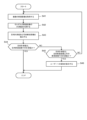
- FIG. 6 is a flowchart illustrating an example of a method for extracting a target result in the ultrasonic diagnostic apparatus shown in FIG.
- FIG. 7 is a diagram for explaining the target result extraction method shown in FIG.
- FIG. 8 is a flowchart for explaining another example (variation 1) of the target result extraction method in the ultrasound diagnostic apparatus shown in FIG.
- FIG. 9 is a flowchart for explaining another example (variation 2) of the target result extraction method in the ultrasonic diagnostic apparatus shown in FIG.
- FIG. 10 is a flowchart for explaining another example (variation 3) of the target result extraction method in the ultrasound diagnostic apparatus shown in FIG.
- FIG. 1 is a block diagram illustrating an example of an ultrasound diagnostic apparatus 10 according to the present embodiment.
- the ultrasound diagnostic device 10 transmits and receives ultrasound to and from a target site within a subject, such as a living body, and generates and displays an ultrasound image of the shape, properties, or dynamics of the biological tissue of the target site based on the received signals obtained from the received ultrasound echoes, for use by doctors and others in image diagnosis.
- the ultrasound diagnostic device 10 includes a device main body 20 and an ultrasound probe 30 (ultrasound probe).
- the ultrasound probe 30 is connected to the device main body 20 via a cable (not shown).
- the ultrasonic probe 30 includes a plurality of transducers each made of a piezoelectric element.
- the transducers are arranged, for example, in a one-dimensional array in the ultrasonic scanning direction.
- the transducers may be arranged in a two-dimensional array.
- each transducer converts the drive signal output from the signal transmission/reception unit 22 of the device main body 20 (described later) into ultrasound and transmits it into the subject, receives the ultrasound echoes reflected within the subject, converts them into received signals, and outputs them to the signal transmission/reception unit 22.
- Various types of probes can be used as the ultrasound probe 30, including, for example, a sector probe using a sector scanning method, a convex probe using a convex scanning method, a linear probe using a linear scanning method, an intracavity probe, etc.
- connection between the device body 20 and the ultrasonic probe 30 may be made by wireless communication such as UWB (Ultra Wide Band) instead of wired communication using a cable.
- UWB Ultra Wide Band
- the device body 20 includes a control unit 21, a signal transmitting/receiving unit 22, an image generating unit 23, a display unit 24, an operation unit 25, and a storage unit 26.
- the device body 20 also includes a measurement unit 27, a target measurement value extracting unit 28, and a target cross-sectional image extracting unit 29.
- the control unit 21 is what is known as a computer, and has a CPU (Central Processing Unit) as a calculation/control device, a ROM (Read Only Memory) as a main memory device, and a RAM (Random Access Memory), etc.
- CPU Central Processing Unit
- ROM Read Only Memory
- RAM Random Access Memory
- the ROM non-temporarily stores programs and setting data, and the CPU reads out a program corresponding to the processing content from the ROM, expands it into the RAM where it is temporarily stored, and executes the expanded program.
- the control unit 21 centrally controls the operation of each functional block of the ultrasound diagnostic device 10.
- the control unit 21 controls the signal transmission/reception unit 22, image generation unit 23, display unit 24, operation unit 25, memory unit 26, measurement unit 27, target measurement value extraction unit 28, and target cross-sectional image extraction unit 29 according to their respective functions, thereby providing overall control of the ultrasound diagnostic device 10.
- the signal transmitting/receiving unit 22 has a transmitting unit and a receiving unit, not shown.
- the transmitting unit supplies a drive signal, which is an electrical signal, to the ultrasonic probe 30 under the control of the control unit 21, causing the ultrasonic probe 30 to generate ultrasonic waves.
- the transmission unit includes, for example, a clock generation circuit, a delay circuit, and a pulse generation circuit.
- the clock generation circuit is a circuit that generates a clock signal that determines the transmission timing and transmission frequency of the drive signal.
- the delay circuit is a circuit that sets a delay time for each individual path corresponding to each transducer of the ultrasound probe 30, and delays the transmission of the drive signal by the set delay time to focus the transmission beam formed by the transmitted ultrasound (transmission beamforming).
- the pulse generation circuit is a circuit that generates a pulse signal as a drive signal at a set voltage and time interval.
- the transmitter configured as described above sequentially switches between multiple transducers to which drive signals are supplied, shifting them by a predetermined number for each transmission and reception of ultrasound, in accordance with the control of the control unit 21, and performs scanning by supplying drive signals to multiple transducers whose outputs are selected.
- the receiving unit receives the received signal, which is an electrical signal, from the ultrasonic probe 30 according to the control of the control unit 21.
- the receiving unit includes, for example, an amplifier, an A/D conversion circuit, and a phasing addition circuit.
- the amplifier is a circuit for amplifying the received signal at a preset amplification factor for each individual path corresponding to each transducer.
- the A/D conversion circuit is a circuit for analog-to-digital conversion (A/D conversion) of the amplified received signal.
- the phasing addition circuit is a circuit for adjusting the time phase by giving a delay time to the A/D converted received signal for each individual path corresponding to each transducer, and adding these (phasing addition) to generate sound ray data. In other words, the phasing addition circuit performs receive beamforming on the received signal for each transducer to generate sound ray data.
- the image generating unit 23 generates cross-sectional images of different cross-sectional positions of the target area of the subject based on sound ray data, which is a reflected signal of ultrasound from the ultrasound probe 30.
- the image generating unit 23 performs envelope detection processing and logarithmic compression on the sound ray data from the receiving unit of the signal transmitting/receiving unit 22 under the control of the control unit 21, and adjusts the dynamic range and gain to convert the brightness.
- the image generating unit 23 generates a B-mode image (hereinafter, a cross-sectional image) as a two-dimensional cross-sectional image.
- the cross-sectional image represents the strength of the received signal by the brightness.
- the image generating unit 23 may also generate an A-mode image, an M-mode image (a two-dimensional cross-sectional image), a Doppler image, a color mode image, or a three-dimensional image.
- the image generating unit 23 also includes an image memory unit (not shown) that is configured with a semiconductor memory such as a dynamic random access memory (DRAM).
- the image generating unit 23 stores the generated cross-sectional images in the image memory unit on a frame-by-frame basis.
- the image generation unit 23 also performs image processing such as image filtering and time smoothing on the cross-sectional image read from the image memory unit, and converts it into a display image pattern for display on the display unit 24.
- the display unit 24 is a display device such as an LCD (Liquid Crystal Display), a CRT (Cathode-Ray Tube) display, an organic EL (Electronic Luminescence) display, an inorganic EL display, or a plasma display.
- the display unit 24 displays the cross-sectional image generated by the image generation unit 23 on a display screen in accordance with the control of the control unit 21.
- the display unit 24 displays the target measurement value and the target cross-sectional image.
- the operation unit 25 includes various switches, buttons, a trackpad, a trackball, a mouse, a keyboard, a touch panel, etc.
- the operation unit 25 performs input such as starting, setting, selecting, operating, and terminating devices and applications.
- the operation unit 25 also performs input such as data such as subject information and various parameters for displaying cross-sectional images on the display unit 24.
- the operation unit 25 outputs a signal corresponding to the input to the control unit 21.
- the memory unit 26 is a storage device capable of writing and reading information, such as a flash memory, a hard disk drive (HDD), or a solid state drive (SSD).
- the memory unit 26 stores, for example, cross-sectional images generated by the image generation unit 23.
- the measurement unit 27 measures the set measurement items on the cross-sectional image of the target part of the subject generated by the image generation unit 23.
- the measurement items are morphological measurements using the cross-sectional image, such as length, area, and volume.
- the measurement items related to the fetus include CRL, bi-parietal diameter (BPD), abdominal circumference (AC), femur length (FL), etc.
- the control unit 21 displays the measurement items such as CRL, BPD, AC, and FL on the display unit 24, and the user (e.g., a doctor) uses the operation unit 25 to select and set the desired measurement item.
- Fig. 2 is a diagram for explaining an example of measurement of a measurement value by the measuring unit 27 in the ultrasound diagnostic device 10.
- Fig. 3 is a diagram for explaining another example of measurement of a measurement value by the measuring unit 27 in the ultrasound diagnostic device 10.
- the measurement unit 27 performs measurements of the set measurement items for all cross-sectional images (here, as an example, all frames F1 to F6) generated by the image generation unit 23. For example, when a cross-sectional image is generated by the image generation unit 23 while the target area of the subject is being scanned with the ultrasound probe 30, the measurement unit 27 performs measurements for all frames by measuring the set measurement items each time an image is generated.
- all cross-sectional images here, as an example, all frames F1 to F6
- the target area of the subject is also scanned with the ultrasound probe 30, and all cross-sectional images generated by the image generation unit 23 are stored in the memory unit 26. After the scan is completed, measurements may be performed for all frames by measuring the set measurement items for all cross-sectional images stored (saved) in the memory unit 26 by the scan. In this case, the target measurement value extraction unit 28 and target cross-sectional image extraction unit 29, which will be described later, are implemented after the measurements are completed.
- the measurement unit 27 may measure the set measurement items for some of the cross-sectional images generated by the image generation unit 23 (here, as an example, frames F2 to F5 out of all frames F1 to F6).
- the ultrasound diagnostic device 10 has a measurement mode for a specific measurement item (e.g., CRL measurement mode, etc.) as a function.
- the set measurement items are measured for the cross-sectional images (frames) generated by the image generation unit 23 during the period in which the measurement mode is selected.
- the user may also specify the measurement period (start time and end time) for measuring the measurement items, and in this case, the set measurement items are measured for the cross-sectional images (frames) generated by the image generation unit 23 during the specified measurement period.
- the measurement unit 27 when measuring the CRL, it is possible that the fetus, which is the target site, is not visible in the cross-sectional image. Even in this case, the measurement unit 27 performs the measurement and sets the measurement value to 0. It is also possible that only a portion of the fetus, which is the target site, is visible in the cross-sectional image (for example, frames F1 and F2 in FIG. 2). Even in this case, the measurement unit 27 performs the measurement and measures the measurement value of the portion presumed to be the target site. In this case, the measurement value will be smaller than the measurement value in the cross-sectional image in the midsagittal plane, which is the appropriate cross-sectional position.
- the target part to be measured is recognized, for example, using a learning processing unit and a learning model described below.
- the target measurement value extraction unit 28 extracts a target measurement value that is the measurement objective based on the measurement results of multiple measurement values measured by the measurement unit 27.
- FIG. 4 is a diagram illustrating an example of target measurement value extraction by the target measurement value extraction unit 28 in an ultrasound diagnostic device.
- Figure 5 is a diagram illustrating another example of target measurement value extraction by the target measurement value extraction unit 28 in an ultrasound diagnostic device 10.
- the target measurement value extraction unit 28 extracts target measurement values from the multiple measurement values measured by the measurement unit 27 based on the tendency of change in the measurement values relative to the cross-sectional position (measurement results).
- the measurement value is largest in the cross-sectional image (frame F4) in the midsagittal plane of the fetus, and the measurement values are small in the other cross-sectional images (frames F1 to F3, F5). Therefore, in this case, the target measurement value is extracted based on the maximum value (measurement result) of the multiple measurement values.
- frame F4 with the maximum value may be used as the target cross-sectional image (or candidate target cross-sectional image) described below.
- the target measurement value may be extracted based on the minimum value of multiple measurement values.
- the change in measurement value with respect to cross-sectional position has one maximum value (or minimum value), as illustrated in Figure 4.
- there may be a maximum value or a minimum value in which case the target measurement value may be extracted based on the maximum or minimum value of multiple measurement values. In this way, the target measurement value is extracted based on the extreme value (measurement result) of multiple measurement values.
- the measurement value in the center frame F5 of frames F4 to F6 having the maximum value is set as the target measurement value.
- the center frame F5 may be set as the target cross-sectional image (or candidate target cross-sectional image) described below.
- the target cross-sectional image extraction unit 29 extracts a target cross-sectional image that is the target cross-sectional position based on the evaluation results of the multiple cross-sectional images generated by the image generation unit 23.
- the cross-sectional position of the fetus's midsagittal plane is the target cross-sectional position, so the target cross-sectional image at that position is evaluated and extracted, for example, using the score described below.
- the target cross-sectional image extraction unit 29 has, for example, a learning processing unit and a learning model (not shown) to obtain a score for extracting the target cross-sectional image.
- the learning processing unit generates a learning model, for example, by deep learning using training data.
- the training data may be, for example, cross-sectional images of a fetus including the midsagittal plane, and by repeatedly performing supervised learning using a large amount of diverse training data, the learning model is optimized so that appropriate outputs can be obtained for various inputs.
- the learning model is mainly composed of, for example, a neural network.
- the learning model outputs a score for each identified target part based on the multiple cross-sectional images generated by the image generation unit 23.
- the score indicates the appropriateness of the identified target part, and target cross-sectional images with high scores (high appropriateness) are extracted based on the scores in the multiple cross-sectional images.
- the target measurement value extraction unit 28 and the target cross-sectional image extraction unit 29 extract the target measurement value and the target cross-sectional image, respectively. Then, when the target measurement value and the target cross-sectional image are determined to be optimal by a judgment described below, the target measurement value and the target cross-sectional image determined to be optimal are displayed on the display unit 24 and presented to the user.
- the signal transmission/reception unit 22, image generation unit 23, measurement unit 27, target measurement value extraction unit 28, and target cross-sectional image extraction unit 29 described above are configured, for example, with dedicated or general-purpose hardware (electronic circuits) according to each process.
- the signal transmission/reception unit 22, image generation unit 23, measurement unit 27, target measurement value extraction unit 28, and target cross-sectional image extraction unit 29 may be configured so that the processing in each unit is executed by a CPU or a GPU (Graphics Processing Unit). In this case, the CPU or GPU will have a processing program that executes the processing of each unit.
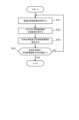
- [Target result extraction method] 6 is a flowchart for explaining an example of a target result extraction method in the ultrasound diagnostic device 10.
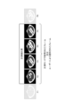
- FIG. 7 is a diagram for explaining the target result extraction method shown in FIG. 6. The result extraction method is performed by executing a target result extraction program by the control unit 21. Note that, in the following, as an example, a case where CRL measurement is performed will be described.
- Step S11 When a user (e.g., a doctor) places the ultrasound probe 30 of the ultrasound diagnostic device 10 against the abdomen of a pregnant woman as a subject and scans an area where a fetus is present as a target site, the control unit 21 acquires a plurality of cross-sectional images using the signal transmission/reception unit 22 and the image generation unit 23. As an example, it is assumed that the control unit 21 acquires cross-sectional images of frames F1 to F5 as shown in FIG.
- Step S12 The control unit 21 measures the measurement values of each cross-sectional image by the measurement unit 27.
- the CRL is measured, and for example, when a cross-sectional image is generated during scanning with the ultrasound probe 30, the CRL measurement is performed each time the image is generated, thereby performing measurements for all frames F1 to F5.
- Step S13 The control unit 21 extracts target measurement values and target cross-sectional images using a target measurement value extraction unit 28 and a target cross-sectional image extraction unit 29.
- the target measurement value extraction unit 28 and the target cross-sectional image extraction unit 29 are executed in parallel (simultaneously) to extract operation target measurement values and target cross-sectional images, respectively.
- the target cross-sectional image extraction unit may be executed after the target measurement value extraction unit is executed.
- the target measurement value extraction unit 28 extracts the maximum measurement value as the target measurement value based on the maximum value of the multiple measurement values, as described in FIG. 4, for example. Also, the target cross-sectional image extraction unit 29 extracts the target cross-sectional image with the high score based on the scores in the multiple cross-sectional images, as described above.
- Step S14 The control unit 21 determines whether the target measurement value is a measurement value in the target cross-sectional image. If the target measurement value is a measurement value in the target cross-sectional image (YES), the series of flows ends, and if the target measurement value is not a measurement value in the target cross-sectional image (NO), the process returns to step S11.
- the target measurement value extracted by the target measurement value extraction unit 28 is the maximum measurement value among multiple measurement values, and therefore in the case of CRL measurement, it can be determined to be the optimal target measurement value. Furthermore, if the target measurement value is a measurement value at the target cross-sectional image, the target cross-sectional image can also be determined to be optimal. Therefore, when the target measurement value is a measurement value at the target cross-sectional image, the control unit 21 will display the target measurement value and target cross-sectional image determined to be optimal on the display unit 24 and present them to the user. In this way, the target measurement value and target cross-sectional image determined to be optimal are displayed on the display unit 24 and presented to the user, improving the accuracy of measurements during diagnosis and improving efficiency.
- the control unit 21 determines that the cross-sectional image of frame F4 is the optimal target cross-sectional image, since, of the measurement values 3 to 5 of frames F3 to F5, measurement value 4 in frame F4 is the target measurement value.
- the control unit 21 prompts the user to perform remeasurement by displaying a message such as "Please check the placement of the ultrasound probe 30" on the display unit 24.
- the ultrasound diagnostic device 10 of this embodiment includes a target measurement value extraction unit and a target cross-sectional image extraction unit.
- the target measurement value extraction unit extracts a target measurement value that is the measurement target based on the measurement results of multiple measurement values.
- the target cross-sectional image extraction unit extracts a target cross-sectional image that is the target cross-sectional position based on the evaluation results of the multiple cross-sectional images.
- the ultrasound diagnostic device 10 of this embodiment configured as described above extracts the target measurement value that is the measurement objective based on the measurement results of multiple measurement values, for example, based on the trend of change or extreme values of the multiple measurement values, so that the optimal measurement value can be extracted.
- the target cross-sectional image that is the target cross-sectional position can be extracted based on the evaluation results of multiple cross-sectional images, for example, based on the above-mentioned score.
- the user can automatically obtain the optimal target measurement value and target cross-sectional image by simply scanning the target area (e.g., fetus) with the ultrasound probe 30, without performing other operations, for example, freezing the cross-sectional image or setting the measurement position.
- the accuracy of measurement during diagnosis can be improved, and efficiency can also be improved.
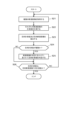
- FIG. 8 is a flowchart illustrating another example of a target result extraction method in the ultrasound diagnostic apparatus 10.
- steps S21 to S23 and step S26 are the same as steps S11 to S13 and step S14 in the flowchart shown in FIG. 6. Therefore, the differences from the flowchart shown in FIG. 6 will be mainly explained here.
- Step S24 The control unit 21 checks whether or not there are multiple target measurement values extracted by the target measurement value extraction unit 28. If there are multiple target measurement values (YES), the process proceeds to step S25, and if there are not multiple target measurement values (NO), the process proceeds to step S26.
- Step S25 When there are a plurality of target measurement values (target measurement value candidates), the control unit 21 determines the target measurement value of the target cross-sectional image with the highest score as the optimal target measurement value based on the scores in the plurality of cross-sectional images.
- the optimal target measurement value can be determined based on the scores in multiple cross-sectional images.
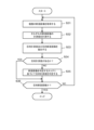
- FIG. 9 is a flowchart illustrating another example of a target result extraction method in the ultrasound diagnostic apparatus 10.
- steps S31 to S33 and step S36 are the same as steps S11 to S13 and step S14 in the flowchart shown in FIG. 6. Therefore, here too, differences from the flowchart shown in FIG. 6 will be mainly explained.
- Step S34 The control unit 21 checks whether or not there is a target measurement value extracted by the target measurement value extraction unit 28. If there is a target measurement value (YES), the process proceeds to step S36, and if there is no target measurement value (NO), the process proceeds to step S35.
- Step S35 When there is no target measurement value, the control unit 21 determines the measurement value of the target cross-sectional image with the highest score as the optimal target measurement value, based on the scores in the multiple cross-sectional images.
- the optimal target measurement value can be determined based on the scores in multiple cross-sectional images.
- FIG. 10 is a flowchart illustrating another example of a target result extraction method in the ultrasound diagnostic apparatus 10.
- steps S41 to S44 are the same as steps S11 to S14 in the flowchart shown in FIG. 6. Therefore, here too, differences from the flowchart shown in FIG. 6 will be mainly explained.
- Step S45 The control unit 21 checks whether the target measurement value extracted by the target measurement value extraction unit 28 is a measurement value in a cross-sectional image other than the target cross-sectional image extracted by the target cross-sectional image extraction unit 29. If the target measurement value is a measurement value in a cross-sectional image other than the target cross-sectional image (YES), the process proceeds to step S46, and if the target measurement value is not a measurement value in a cross-sectional image other than the target cross-sectional image (NO), the process returns to step S41.
- Step S46 If the target measurement value is a measurement value in a cross-sectional image other than the target cross-sectional image, the control unit 21 notifies the user of that fact, displays the target measurement value and the measurement value for confirmation on the display unit 24, and ends the process. In this case, the above-mentioned score may also be displayed on the display unit 24.
- the target measurement value is a measurement value on a cross-sectional image other than the target cross-sectional image
- information necessary for the user's judgment is displayed on the display unit 24 to request the user's confirmation.
- Ultrasound diagnostic device 20 Device body 21 Control unit 22 Signal transmission/reception unit 23 Image generation unit 24 Display unit 25 Operation unit 26 Storage unit 27 Measurement unit 28 Target measurement value extraction unit 29 Target cross-sectional image extraction unit 30 Ultrasound probe
Landscapes
- Life Sciences & Earth Sciences (AREA)
- Health & Medical Sciences (AREA)
- Biomedical Technology (AREA)
- Biophysics (AREA)
- Nuclear Medicine, Radiotherapy & Molecular Imaging (AREA)
- Pathology (AREA)
- Radiology & Medical Imaging (AREA)
- Engineering & Computer Science (AREA)
- Physics & Mathematics (AREA)
- Heart & Thoracic Surgery (AREA)
- Medical Informatics (AREA)
- Molecular Biology (AREA)
- Surgery (AREA)
- Animal Behavior & Ethology (AREA)
- General Health & Medical Sciences (AREA)
- Public Health (AREA)
- Veterinary Medicine (AREA)
- Ultra Sonic Daignosis Equipment (AREA)
Abstract
超音波診断装置は、探触子から出力する超音波の反射信号に基づいて、被検体の対象部位について、異なる断面位置の断面画像を生成する画像生成部と、生成された複数の断面画像のそれぞれに対して、対象部位に関する計測値を計測する計測部と、複数の計測値の計測結果に基づいて、計測目的となる目的計測値を抽出する目的計測値抽出部と、複数の断面画像の評価結果に基づいて、目的の断面位置となる目的断面画像を抽出する目的断面画像抽出部と、を備える。
Description
本発明は、超音波診断装置、目的結果抽出方法及び目的結果抽出プログラムに関する。
超音波診断装置は、例えば、被検体の対象部位の断面画像(例えば、Bモード画像)を生成し、生成された断面画像を超音波診断装置の表示部に表示するよう構成されている。医師等のユーザーは、表示部に表示された断面画像を参照して、対象部位の診断を行ったり、対象部位に関する計測を行ったりするようにしている。
対象部位に関する計測を行うため、例えば、特許文献1においては、生成された断面画像が対象部位の計測に適しているかどうかを評価し、計測に適していると評価された断面画像を用いて、対象部位の計測を行うようにしている。
超音波診断装置において、例えば、胎児の頭殿長(crown rump length;以降、CRL)の計測を実施する場合には、ユーザーは、超音波探触子を被検体である妊婦に当てて、腹部又は経腟で走査するようにしている。
CRLのような計測には正確性と効率性が求められるが、手動又は半自動で計測を行う場合、ユーザー自身で計測する断面画像を選択し、かつ、ユーザー自身で計測された計測値が目的の計測値であるかどうかを判断する必要があった。そのため、正確性が低く、手間がかかり、効率も悪かった。
特許文献1においては、上述したように、超音波診断装置側で、生成された断面画像が対象部位の計測に適しているかどうかを評価し、計測に適していると評価された断面画像を用いて、対象部位の計測を行うようにしている。しかしながら、特許文献1においては、生成された断面画像が対象部位の計測に適しているかどうかを評価しているだけであり、計測された計測値が目的の計測値であるかどうかを判断している訳ではないため、必ずしも、正確とは言えなかった。また、複数の断面画像が対象部位の計測に適していると評価される場合もあり、この場合も、計測された計測値が目的の計測値であるかどうかを判断している訳ではないため、必ずしも、正確とは言えなかった。
本発明の目的は、最適な計測値及び最適な断面画像を抽出可能な超音波診断装置、目的結果抽出方法及び目的結果抽出プログラムを提供することにある。
本発明に係る超音波診断装置は、
探触子から出力する超音波の反射信号に基づいて、被検体の対象部位について、異なる断面位置の断面画像を生成する画像生成部と、
生成された複数の前記断面画像のそれぞれに対して、前記対象部位に関する計測値を計測する計測部と、
複数の前記計測値の計測結果に基づいて、計測目的となる目的計測値を抽出する目的計測値抽出部と、
複数の前記断面画像の評価結果に基づいて、目的の断面位置となる目的断面画像を抽出する目的断面画像抽出部と、
を備える。
探触子から出力する超音波の反射信号に基づいて、被検体の対象部位について、異なる断面位置の断面画像を生成する画像生成部と、
生成された複数の前記断面画像のそれぞれに対して、前記対象部位に関する計測値を計測する計測部と、
複数の前記計測値の計測結果に基づいて、計測目的となる目的計測値を抽出する目的計測値抽出部と、
複数の前記断面画像の評価結果に基づいて、目的の断面位置となる目的断面画像を抽出する目的断面画像抽出部と、
を備える。
本発明に係る目的結果抽出方法は、
探触子から出力する超音波の反射信号に基づいて、被検体の対象部位について、異なる断面位置の断面画像を生成し、
生成された複数の前記断面画像のそれぞれに対して、前記対象部位に関する計測値を計測し、
複数の前記計測値の計測結果に基づいて、計測目的となる目的計測値を抽出し、
複数の前記断面画像の評価結果に基づいて、目的の断面位置となる目的断面画像を抽出する。
探触子から出力する超音波の反射信号に基づいて、被検体の対象部位について、異なる断面位置の断面画像を生成し、
生成された複数の前記断面画像のそれぞれに対して、前記対象部位に関する計測値を計測し、
複数の前記計測値の計測結果に基づいて、計測目的となる目的計測値を抽出し、
複数の前記断面画像の評価結果に基づいて、目的の断面位置となる目的断面画像を抽出する。
本発明に係る目的結果抽出プログラムは、
コンピューターに、
探触子から出力する超音波の反射信号に基づいて、被検体の対象部位について、異なる断面位置の断面画像を生成する処理と、
生成された複数の前記断面画像のそれぞれに対して、前記対象部位に関する計測値を計測する処理と、
複数の前記計測値の計測結果に基づいて、計測目的となる目的計測値を抽出する処理と、
複数の前記断面画像の評価結果に基づいて、目的の断面位置となる目的断面画像を抽出する処理と、
を実行させる。
コンピューターに、
探触子から出力する超音波の反射信号に基づいて、被検体の対象部位について、異なる断面位置の断面画像を生成する処理と、
生成された複数の前記断面画像のそれぞれに対して、前記対象部位に関する計測値を計測する処理と、
複数の前記計測値の計測結果に基づいて、計測目的となる目的計測値を抽出する処理と、
複数の前記断面画像の評価結果に基づいて、目的の断面位置となる目的断面画像を抽出する処理と、
を実行させる。
本発明によれば、最適な計測値及び最適な断面画像を抽出することができる。
以下、本発明の実施の形態について、図面を参照して詳細に説明する。
[超音波診断装置]
図1は、本実施の形態に係る超音波診断装置10の一例を説明するブロック図である。
図1は、本実施の形態に係る超音波診断装置10の一例を説明するブロック図である。
超音波診断装置10は、生体等の被検体内の対象部位に対して超音波の送受信を行い、受信した超音波エコーから得られた受信信号に基づいて、対象部位の生体組織の形状、性状又は動態を超音波画像として生成、表示し、医師等が画像診断するために用いられる。
超音波診断装置10は、図1に示すように、装置本体20、超音波探触子30(超音波プローブ)を備える。超音波診断装置10において、超音波探触子30は、ケーブル(図示省略)を介して、装置本体20と接続されている。
[超音波探触子]
超音波探触子30は、詳細な図示は省略するが、圧電素子からなる振動子を複数備えている。振動子は、例えば、超音波の走査方向に一次元アレイ状に複数配列されている。なお、振動子は、二次元アレイ状に配列されたものであってもよい。
超音波探触子30は、詳細な図示は省略するが、圧電素子からなる振動子を複数備えている。振動子は、例えば、超音波の走査方向に一次元アレイ状に複数配列されている。なお、振動子は、二次元アレイ状に配列されたものであってもよい。
超音波探触子30において、それぞれの振動子は、後述する装置本体20の信号送受信部22から出力された駆動信号を超音波に変換して被検体内へ送信し、被検体内で反射した超音波エコーを受信して受信信号に変換し、信号送受信部22へ出力する。
超音波探触子30としては、例えば、セクター走査方式のセクタープローブ、コンベックス走査方式のコンベックスプローブ、リニア走査方式のリニアプローブ、体腔内プローブ等を含む様々な種類のプローブを使用可能である。
なお、装置本体20と超音波探触子30との接続は、ケーブルによる有線通信に代えて、UWB(Ultra Wide Band)等の無線通信により行ってもよい。
[装置本体]
装置本体20は、図1に示すように、制御部21、信号送受信部22、画像生成部23、表示部24、操作部25、記憶部26を備える。また、本実施の形態において、装置本体20は、計測部27、目的計測値抽出部28、目的断面画像抽出部29を備える。
装置本体20は、図1に示すように、制御部21、信号送受信部22、画像生成部23、表示部24、操作部25、記憶部26を備える。また、本実施の形態において、装置本体20は、計測部27、目的計測値抽出部28、目的断面画像抽出部29を備える。
制御部21は、所謂、コンピューターであり、演算/制御装置としてのCPU(Central Processing Unit)、主記憶装置としてのROM(Read Only Memory)及びRAM(Random Access Memory)等を有する。
制御部21において、ROMは、プログラムや設定データを非一時的に記憶し、CPUは、ROMから処理内容に応じたプログラムを読み出して一時的に記憶するRAMに展開し、展開したプログラムを実行する。これにより、制御部21は、超音波診断装置10の各機能ブロックの動作を集中制御する。つまり、制御部21は、信号送受信部22、画像生成部23、表示部24、操作部25、記憶部26、計測部27、目的計測値抽出部28及び目的断面画像抽出部29を、それぞれの機能に応じて制御することによって、超音波診断装置10の全体制御を行う。
信号送受信部22は、図示は省略するが送信部と受信部とを有する。送信部は、制御部21の制御に従って、超音波探触子30に電気信号である駆動信号を供給し、超音波探触子30から超音波を発生させる。
詳細な図示は省略するが、送信部は、例えば、クロック発生回路、遅延回路、パルス発生回路を備えている。クロック発生回路は、駆動信号の送信タイミングや送信周波数を決定するクロック信号を発生させる回路である。遅延回路は、超音波探触子30の振動子毎に対応した個別経路毎に遅延時間を設定し、設定された遅延時間だけ駆動信号の送信を遅延させて送信超音波によって構成される送信ビームの集束(送信ビームフォーミング)等を行うための回路である。パルス発生回路は、設定された電圧および時間間隔で駆動信号としてのパルス信号を発生させるための回路である。
上述のように構成された送信部は、制御部21の制御に従って、駆動信号を供給する複数の振動子を、超音波の送受信毎に所定数ずらしながら順次切り替え、出力の選択された複数の振動子に対して駆動信号を供給することにより走査(スキャン)を行う。
信号送受信部22において、受信部は、制御部21の制御に従って、超音波探触子30からの電気信号である受信信号を受信する。
詳細な図示は省略するが、受信部は、例えば、増幅器、A/D変換回路、整相加算回路を備えている。増幅器は、受信信号を、振動子毎に対応した個別経路毎に、予め設定された増幅率で増幅させるための回路である。A/D変換回路は、増幅された受信信号をアナログ-デジタル変換(A/D変換)するための回路である。整相加算回路は、A/D変換された受信信号に対して、振動子毎に対応した個別経路毎に遅延時間を与えて時相を整え、これらを加算(整相加算)して音線データを生成するための回路である。すなわち、整相加算回路は、振動子毎の受信信号に対して受信ビームフォーミングを行って音線データを生成する。
画像生成部23は、超音波探触子30からの超音波の反射信号である音線データに基づいて、被検体の対象部位について、異なる断面位置の断面画像を生成する。
具体的には、画像生成部23は、制御部21の制御に従って、信号送受信部22の受信部からの音線データに対して包絡線検波処理や対数圧縮などを実施し、ダイナミックレンジやゲインの調整を行って輝度変換する。これにより、画像生成部23は、2次元断面画像としてのBモード画像(以下、断面画像)を生成する。すなわち、断面画像は、受信信号の強さを輝度によって表したものである。なお、画像生成部23は、Aモード画像、Mモード画像(2次元断面画像)、ドプラ画像、カラーモード画像又は3次元画像を生成しても良い。
また、画像生成部23は、DRAM(Dynamic Random Access Memory)などの半導体メモリーによって構成された画像メモリー部(図示せず)を備えている。画像生成部23は、生成した断面画像をフレーム単位で画像メモリー部に記憶させる。
また、画像生成部23は、画像メモリー部から読みだした断面画像に対して画像フィルタ処理や時間平滑化処理などの画像処理を施し、表示部24へ表示するための表示画像パターンに変換する。
表示部24は、LCD(Liquid Crystal Display)、CRT(Cathode-Ray Tube)ディスプレイ、有機EL(Electronic Luminescence)ディスプレイ、無機ELディスプレイ、プラズマディスプレイ等の表示装置である。表示部24は、制御部21の制御に従って、画像生成部23により生成された断面画像を表示画面上に表示する。また、表示部24は、後述する目的計測値及び目的断面画像が抽出された場合には、当該目的計測値及び目的断面画像を表示する。
操作部25は、各種スイッチ、ボタン、トラックパッド、トラックボール、マウス、キーボード、タッチパネル等を備える。
操作部25は、例えば、装置やアプリケーションの起動、設定、選択、操作、終了等の入力等を行う。また、操作部25は、被検体の情報等のデータや表示部24に断面画像を表示するための各種パラメーターの入力等を行う。操作部25は、入力に対応する信号を制御部21に出力する。
記憶部26は、フラッシュメモリー、HDD(Hard Disk Drive)、SSD(Solid State Drive)等の情報の書き込み及び読み出しが可能な記憶装置である。記憶部26には、例えば、画像生成部23で生成された断面画像等を記憶する。
計測部27は、画像生成部23で生成された被検体の対象部位の断面画像に対し、設定された計測項目の計測を行う。計測項目は、断面画像を用いた形態的計測、例えば、長さ、面積、体積等である。被検体の対象部位が妊婦の胎児である場合、胎児に関する計測項目としては、CRL、児頭大横径(Bi-Parietal Diameter;以降、BPD)、体幹周囲長(Abdominal Circumference;以降、AC)、大腿骨長(Femur Length;以降、FL)等がある。制御部21は、CRL、BPD、AC、FL等の計測項目を表示部24に表示し、ユーザー(例えば、医師)は、操作部25を用いて、所望の計測項目を選択し、設定する。
計測部27について、図2及び図3を参照して説明をする。図2は、超音波診断装置10における計測部27による計測値計測の一例を説明する図である。また、図3は、超音波診断装置10における計測部27による計測値計測の他の一例を説明する図である。
計測部27は、図2に示すように、画像生成部23で生成された全ての断面画像(ここでは、一例として、全フレームF1~F6)に対して、設定された計測項目の計測を行う。例えば、被検体の対象部位を超音波探触子30で走査中に画像生成部23で断面画像が生成されると、生成される度に、設定された計測項目の計測を行うことで、全フレームに対する計測を行う。
また、被検体の対象部位を超音波探触子30で走査して、画像生成部23で生成された全ての断面画像を記憶部26に記憶する。そして、走査終了後、当該走査により記憶部26に記憶(保存)された全ての断面画像に対して、設定された計測項目の計測を行うことで、全フレームに対する計測を行ってもよい。この場合、後述する目的計測値抽出部28や目的断面画像抽出部29は、当該計測の終了後、実施される。
また、計測部27は、図3に示すように、画像生成部23で生成された断面画像の一部の断面画像(ここでは、一例として、全フレームF1~F6中のフレームF2~F5)に対して、設定された計測項目の計測を行ってもよい。例えば、超音波診断装置10の機能として、特定の計測項目に対する計測モード(例えば、CRL計測モード等)があるとする。この場合には、当該計測モードを選択している期間中に、画像生成部23で生成された断面画像(フレーム)に対して、設定された計測項目の計測を行う。また、ユーザーの操作により、計測項目を計測する計測期間(開始時間と終了時間)を指定してもよく、その場合も、指定された計測期間中に、画像生成部23で生成された断面画像(フレーム)に対して、設定された計測項目の計測を行うことになる。
ここで、例えば、CRLを計測する場合、対象部位である胎児が断面画像に写っていないことがあり得る。その場合でも、計測部27は、計測を行い、計測値を0とする。また、対象部位である胎児が断面画像に一部しか写っていないこともあり得る(例えば、図2中のフレームF1、F2)。その場合でも、計測部27は、計測を行い、対象部位と推測される部分の計測値を計測する。この場合の計測値は、適切な断面位置である正中矢状面での断面画像における計測値より小さい計測値となる。
なお、計測部27において、計測される対象部位は、例えば、後述する学習処理部及び学習モデルを用いて認識するようにしている。
目的計測値抽出部28は、計測部27で計測された複数の計測値の計測結果に基づいて、計測目的となる目的計測値を抽出する。
目的計測値抽出部28について、図4及び図5を参照して説明をする。図4は、超音波診断装置における目的計測値抽出部28による目的計測値抽出の一例を説明する図である。また、図5は、超音波診断装置10における目的計測値抽出部28による目的計測値抽出の他の一例を説明する図である。
目的計測値抽出部28は、計測部27で計測された複数の計測値について、断面位置に対する計測値の変化の傾向(計測結果)に基づいて、目的計測値を抽出する。
例えば、CRLを計測する場合、図4に示すように、胎児の正中矢状面での断面画像(フレームF4)における計測値が最も大きく、それ以外の断面画像(フレームF1~F3、F5)における計測値は小さい。従って、この場合、複数の計測値のうちの最大値(計測結果)に基づいて、目的計測値を抽出する。このとき、最大値を有するフレームF4を後述する目的断面画像(又は、目的断面画像候補)としてもよい。
計測項目によっては、複数の計測値のうちの最小値に基づいて、目的計測値を抽出してもよい。また、断面位置に対する計測値の変化は、図4に例示するように、1つの最大値(又は最小値)を有することが理想的である。しかしながら、計測項目によっては、極大値や極小値を有する場合もあり、その場合は、複数の計測値のうちの極大値又は極小値に基づいて、目的計測値を抽出してもよい。このように、目的計測値は、複数の計測値のうちの極値(計測結果)に基づいて、抽出する。
また、図5に示すように、複数の計測値において、最大値が複数ある場合もあり、その場合は、最大値を有するフレームF4~F6の中央のフレームF5における計測値を目的計測値とする。このとき、中央のフレームF5を後述する目的断面画像(又は、目的断面画像候補)としてもよい。
目的断面画像抽出部29は、画像生成部23で生成された複数の断面画像の評価結果に基づいて、目的の断面位置となる目的断面画像を抽出する。
例えば、CRLを計測する場合、胎児の正中矢状面となる断面位置が目的の断面位置となるので、当該位置となる目的断面画像を、例えば、以下に説明するスコアを用いて評価して抽出する。
目的断面画像抽出部29は、目的断面画像を抽出するスコアを求めるため、例えば、学習処理部と学習モデルとを有する(図示省略)。
学習処理部は、例えば、教師データを用いた深層学習によって、学習モデルを生成する。教師データは、例えば、正中矢状面を含む胎児の断面画像等であり、大量かつ多様な教師データを用いた教師あり学習を繰り返し実行することで、様々な入力に対して適切な出力が得られるように、学習モデルが最適化される。
学習モデルは、例えば、ニューラルネットワークを主体に構成されている。学習モデルは、画像生成部23で生成された複数の断面画像に基づいて、識別された対象部位のスコアをそれぞれ出力する。スコアは、識別された対象部位の適正度を示しており、複数の断面画像におけるスコアに基づいて、スコアが高い(適正度が高い)目的断面画像を抽出する。
このようにして、目的計測値抽出部28及び目的断面画像抽出部29は、それぞれ、目的計測値及び目的断面画像を抽出する。そして、後述する判定により最適と判定されると、最適と判定された目的計測値及び目的断面画像は、表示部24に表示されて、ユーザーに提示される。
上述した信号送受信部22、画像生成部23、計測部27、目的計測値抽出部28、目的断面画像抽出部29は、例えば、各処理に応じた専用又は汎用のハードウェア(電子回路)で構成されている。なお、信号送受信部22、画像生成部23、計測部27、目的計測値抽出部28、目的断面画像抽出部29は、各部における処理を、CPUやGPU(Graphics Processing Unit)で実行するよう構成されてもよい。この場合、CPUやGPUは、各部の処理を行う処理プログラムを有することになる。
[目的結果抽出方法]
図6は、超音波診断装置10における目的結果抽出方法の一例を説明するフローチャートである。図7は、図6に示した目的結果抽出方法を説明する図である。超音波診断装置10における目的結果抽出方法は、制御部21が目的結果抽出プログラムを実行することで行われる。なお、以降でも、一例として、CRL計測を実施する場合を例に取って説明を行う。
図6は、超音波診断装置10における目的結果抽出方法の一例を説明するフローチャートである。図7は、図6に示した目的結果抽出方法を説明する図である。超音波診断装置10における目的結果抽出方法は、制御部21が目的結果抽出プログラムを実行することで行われる。なお、以降でも、一例として、CRL計測を実施する場合を例に取って説明を行う。
(ステップS11)
ユーザー(例えば、医師)が、超音波診断装置10の超音波探触子30を被検体である妊婦の腹部等に当てて、対象部位である胎児が存在する領域を走査することにより、制御部21は、信号送受信部22及び画像生成部23により、複数の断面画像を取得する。一例として、図7に示すように、制御部21がフレームF1~F5の断面画像を取得したとする。
ユーザー(例えば、医師)が、超音波診断装置10の超音波探触子30を被検体である妊婦の腹部等に当てて、対象部位である胎児が存在する領域を走査することにより、制御部21は、信号送受信部22及び画像生成部23により、複数の断面画像を取得する。一例として、図7に示すように、制御部21がフレームF1~F5の断面画像を取得したとする。
(ステップS12)
制御部21は、計測部27により、それぞれの断面画像の計測値を計測する。ここでは、上述したように、CRLを計測しており、例えば、超音波探触子30での走査中に断面画像が生成されると、生成される度に、CRL計測を行うことで、全フレームF1~F5に対する計測を行う。
制御部21は、計測部27により、それぞれの断面画像の計測値を計測する。ここでは、上述したように、CRLを計測しており、例えば、超音波探触子30での走査中に断面画像が生成されると、生成される度に、CRL計測を行うことで、全フレームF1~F5に対する計測を行う。
(ステップS13)
制御部21は、目的計測値抽出部28及び目的断面画像抽出部29により、目的計測値及び目的断面画像を抽出する。ここでは、目的計測値抽出部28及び目的断面画像抽出部29は、並列に(同時に)実施され、それぞれ、動作目的計測値及び目的断面画像を抽出する。なお、本実施の形態においては、上記特許文献1とは異なり、目的断面画像抽出部は、目的計測値抽出部の実施後に実施されてもよい。
制御部21は、目的計測値抽出部28及び目的断面画像抽出部29により、目的計測値及び目的断面画像を抽出する。ここでは、目的計測値抽出部28及び目的断面画像抽出部29は、並列に(同時に)実施され、それぞれ、動作目的計測値及び目的断面画像を抽出する。なお、本実施の形態においては、上記特許文献1とは異なり、目的断面画像抽出部は、目的計測値抽出部の実施後に実施されてもよい。
目的計測値抽出部28は、例えば、図4で説明したように、複数の計測値のうちの最大値に基づいて、最大値である計測値を目的計測値として抽出する。また、目的断面画像抽出部29は、上述したように、複数の断面画像におけるスコアに基づいて、スコアが高い目的断面画像を抽出する。
(ステップS14)
制御部21は、目的計測値が目的断面画像での計測値かどうかを判定する。目的計測値が目的断面画像での計測値である場合(YES)、一連のフローを終了し、目的計測値が目的断面画像での計測値でない場合(NO)、ステップS11へ戻る。
制御部21は、目的計測値が目的断面画像での計測値かどうかを判定する。目的計測値が目的断面画像での計測値である場合(YES)、一連のフローを終了し、目的計測値が目的断面画像での計測値でない場合(NO)、ステップS11へ戻る。
目的計測値抽出部28で抽出された目的計測値は、複数の計測値のうち、最大値の計測値であるので、CRLの計測の場合、最適な目的計測値と判定することができる。そして、当該目的計測値が目的断面画像での計測値である場合には、当該目的断面画像も最適と判定することができる。従って、目的計測値が目的断面画像での計測値である場合、制御部21は、最適と判定された目的計測値及び目的断面画像を、表示部24に表示して、ユーザーに提示することになる。このようにして、最適と判定された目的計測値及び目的断面画像を、表示部24に表示し、ユーザーに提示するので、診断時の計測の正確性が向上し、効率も向上する。
例えば、図7に示すように、目的計測値抽出部28で抽出された目的計測値がフレームF4での計測値4であり、目的断面画像抽出部29で抽出された目的断面画像(目的断面画像候補)がフレームF3~F5であるとする。この場合、制御部21は、フレームF3~F5の計測値3~5のうち、フレームF4での計測値4が目的計測値であるので、フレームF4の断面画像を最適な目的断面画像と判定する。
一方、目的計測値が目的断面画像での計測値でない場合には、超音波探触子30の配置位置が悪い等の問題がある可能性がある。そのため、制御部21は、例えば、「超音波探触子30の配置位置を確認して下さい」等のメッセージを表示部24に表示して、再計測を行うようユーザーに促すようにする。
以上説明したように、本実施の形態の超音波診断装置10は、目的計測値抽出部と目的断面画像抽出部とを備える。目的計測値抽出部は、複数の計測値の計測結果に基づいて、計測目的となる目的計測値を抽出する。また、目的断面画像抽出部は、複数の断面画像の評価結果に基づいて、目的の断面位置となる目的断面画像を抽出する。
このように構成した本実施の形態の超音波診断装置10によれば、複数の計測値の計測結果に基づいて、例えば、複数の計測値の変化の傾向や極値に基づいて、計測目的となる目的計測値を抽出するので、最適な計測値を抽出することができる。また、複数の断面画像の評価結果に基づいて、例えば、上述したスコアに基づいて、目的の断面位置となる目的断面画像を抽出することができる。つまり、ユーザーは、対象部位(例えば、胎児)を超音波探触子30で走査するだけで、他の操作、例えば、断面画像をフリーズさせたり、計測位置を設定したりすることなく、最適な目的計測値及び目的断面画像を自動的に取得することができる。その結果、診断時の計測の正確性を向上させ、効率も向上させることができる。
<変形例1>
図8は、超音波診断装置10における目的結果抽出方法の他の一例を説明するフローチャートである。
図8は、超音波診断装置10における目的結果抽出方法の他の一例を説明するフローチャートである。
本変形例において、ステップS21~S23及びステップS26は、図6に示したフローチャートにおけるステップS11~S13及びステップS14と同じである。従って、ここでは、主に、図6に示したフローチャートとの相違点を説明する。
(ステップS24)
制御部21は、目的計測値抽出部28で抽出された目的計測値が複数かどうかを確認する。目的計測値が複数である場合(YES)、ステップS25へ進み、目的計測値が複数でない場合(NO)、ステップS26へ進む。
制御部21は、目的計測値抽出部28で抽出された目的計測値が複数かどうかを確認する。目的計測値が複数である場合(YES)、ステップS25へ進み、目的計測値が複数でない場合(NO)、ステップS26へ進む。
(ステップS25)
目的計測値(目的計測値候補)が複数である場合、制御部21は、複数の断面画像におけるスコアに基づいて、スコアが高い目的断面画像の目的計測値を最適な目的計測値と判定する。
目的計測値(目的計測値候補)が複数である場合、制御部21は、複数の断面画像におけるスコアに基づいて、スコアが高い目的断面画像の目的計測値を最適な目的計測値と判定する。
このように、目的計測値が複数である場合でも、複数の断面画像におけるスコアに基づいて、最適な目的計測値を判定することができる。
<変形例2>
図9は、超音波診断装置10における目的結果抽出方法の他の一例を説明するフローチャートである。
図9は、超音波診断装置10における目的結果抽出方法の他の一例を説明するフローチャートである。
本変形例においても、ステップS31~S33及びステップS36は、図6に示したフローチャートにおけるステップS11~S13及びステップS14と同じである。従って、ここでも、主に、図6に示したフローチャートとの相違点を説明する。
(ステップS34)
制御部21は、目的計測値抽出部28で抽出された目的計測値があるかどうかを確認する。目的計測値がある場合(YES)、ステップS36へ進み、目的計測値がない場合(NO)、ステップS35へ進む。
制御部21は、目的計測値抽出部28で抽出された目的計測値があるかどうかを確認する。目的計測値がある場合(YES)、ステップS36へ進み、目的計測値がない場合(NO)、ステップS35へ進む。
(ステップS35)
目的計測値がない場合、制御部21は、複数の断面画像におけるスコアに基づいて、スコアが高い目的断面画像の計測値を最適な目的計測値と判定する。
目的計測値がない場合、制御部21は、複数の断面画像におけるスコアに基づいて、スコアが高い目的断面画像の計測値を最適な目的計測値と判定する。
このように、目的計測値が抽出できない場合でも、複数の断面画像におけるスコアに基づいて、最適な目的計測値を判定することができる。
<変形例3>
図10は、超音波診断装置10における目的結果抽出方法の他の一例を説明するフローチャートである。
図10は、超音波診断装置10における目的結果抽出方法の他の一例を説明するフローチャートである。
本変形例において、ステップS41~S44は、図6に示したフローチャートにおけるステップS11~S14と同じである。従って、ここでも、主に、図6に示したフローチャートとの相違点を説明する。
(ステップS45)
制御部21は、目的計測値抽出部28で抽出された目的計測値が、目的断面画像抽出部29で抽出された目的断面画像以外の断面画像での計測値かどうかを確認する。目的計測値が目的断面画像以外の断面画像での計測値である場合(YES)、ステップS46へ進み、目的計測値が目的断面画像以外の断面画像での計測値でない場合(NO)、ステップS41へ戻る。
制御部21は、目的計測値抽出部28で抽出された目的計測値が、目的断面画像抽出部29で抽出された目的断面画像以外の断面画像での計測値かどうかを確認する。目的計測値が目的断面画像以外の断面画像での計測値である場合(YES)、ステップS46へ進み、目的計測値が目的断面画像以外の断面画像での計測値でない場合(NO)、ステップS41へ戻る。
(ステップS46)
目的計測値が目的断面画像以外の断面画像での計測値である場合、制御部21は、当該旨をユーザーに通知し、確認を求める目的計測値及び計測値を表示部24に表示して終了する。この場合、上述したスコアも表示部24に表示してもよい。
目的計測値が目的断面画像以外の断面画像での計測値である場合、制御部21は、当該旨をユーザーに通知し、確認を求める目的計測値及び計測値を表示部24に表示して終了する。この場合、上述したスコアも表示部24に表示してもよい。
このように、目的計測値が目的断面画像以外の断面画像での計測値であるには、ユーザーの判断に必要な情報を表示部24に表示して、ユーザーに確認を求めるようにしている。
上記実施の形態や変形例では、何れも本発明を実施するにあたっての具体化の一例を示したものに過ぎず、これらによって本発明の技術的範囲が限定的に解釈されてはならないものである。即ち、本発明はその要旨、又は、その主要な特徴から逸脱することなく、様々な形で実施することができる。
2023年6月9日出願の特願2023-095504の日本出願に含まれる明細書、図面および要約書の開示内容は、すべて本願に援用される。
10 超音波診断装置
20 装置本体
21 制御部
22 信号送受信部
23 画像生成部
24 表示部
25 操作部
26 記憶部
27 計測部
28 目的計測値抽出部
29 目的断面画像抽出部
30 超音波探触子
20 装置本体
21 制御部
22 信号送受信部
23 画像生成部
24 表示部
25 操作部
26 記憶部
27 計測部
28 目的計測値抽出部
29 目的断面画像抽出部
30 超音波探触子
Claims (16)
- 探触子から出力する超音波の反射信号に基づいて、被検体の対象部位について、異なる断面位置の断面画像を生成する画像生成部と、
生成された複数の前記断面画像のそれぞれに対して、前記対象部位に関する計測値を計測する計測部と、
複数の前記計測値の計測結果に基づいて、計測目的となる目的計測値を抽出する目的計測値抽出部と、
複数の前記断面画像の評価結果に基づいて、目的の断面位置となる目的断面画像を抽出する目的断面画像抽出部と、
を備える超音波診断装置。 - 抽出された前記目的計測値及び前記目的断面画像を表示する表示部を備える、
請求項1に記載の超音波診断装置。 - 前記計測値を計測する計測モードを備え、
前記計測モードにおいて、
前記画像生成部は、複数の前記断面画像を生成し、
前記計測部は、前記画像生成部で生成された複数の前記断面画像のそれぞれに対して、前記計測値を計測する、
請求項1に記載の超音波診断装置。 - 前記計測部は、生成された複数の前記断面画像のうち、ユーザーに指定された複数の前記断面画像のそれぞれに対して、前記計測値を計測する、
請求項1に記載の超音波診断装置。 - 前記計測結果は、複数の前記計測値のうちの極値であり、
前記目的計測値抽出部は、前記極値に基づいて、前記目的計測値を抽出する、
請求項1に記載の超音波診断装置。 - 前記計測結果は、前記断面位置に対する前記計測値の変化の傾向であり、
前記目的計測値抽出部は、前記傾向に基づいて、前記目的計測値を抽出する、
請求項1に記載の超音波診断装置。 - 前記評価結果は、前記断面画像における前記対象部位の適正度を評価するスコアであり、
前記目的断面画像抽出部は、前記スコアに基づいて、前記目的断面画像を抽出し、
前記目的計測値抽出部は、前記目的計測値が複数抽出された場合、前記スコアに基づいて、複数抽出された前記目的計測値の中から前記目的計測値を抽出する、
請求項1に記載の超音波診断装置。 - 前記評価結果は、前記断面画像における前記対象部位の適正度を評価するスコアであり、
前記目的断面画像抽出部は、前記スコアに基づいて、前記目的断面画像を抽出し、
前記目的計測値抽出部は、前記目的計測値が抽出されなかった場合、前記スコアに基づいて抽出された前記目的断面画像における目的計測値を前記目的計測値として抽出する、
請求項1に記載の超音波診断装置。 - 前記目的計測値抽出部は、抽出された前記目的計測値が前記目的断面画像抽出部で抽出された前記目的断面画像における計測値である場合、最適な目的計測値が抽出されていると判定する、
請求項1に記載の超音波診断装置。 - 前記表示部は、抽出された前記目的計測値が前記目的断面画像抽出部で抽出された前記目的断面画像における計測値でない場合、当該旨をユーザーに通知し、確認を求める前記目的計測値及び前記計測値を表示する、
請求項2に記載の超音波診断装置。 - 前記対象部位を前記探触子で走査中である場合、
前記計測部は、前記断面画像が生成されると、前記計測値を計測し、
前記目的計測値抽出部は、走査終了後、前記計測結果に基づいて、前記目的計測値を抽出する、
請求項1に記載の超音波診断装置。 - 前記計測部は、保存された複数の前記断面画像のそれぞれに対して、前記計測値を計測し、
前記目的計測値抽出部は、計測終了後、前記計測結果に基づいて、前記目的計測値を抽出する、
請求項1に記載の超音波診断装置。 - 前記目的計測値抽出部及び前記目的断面画像抽出部は、並列に実施される、
請求項1に記載の超音波診断装置。 - 前記目的断面画像抽出部は、前記目的計測値抽出部の実施後に実施される、
請求項1に記載の超音波診断装置。 - 探触子から出力する超音波の反射信号に基づいて、被検体の対象部位について、異なる断面位置の断面画像を生成し、
生成された複数の前記断面画像のそれぞれに対して、前記対象部位に関する計測値を計測し、
複数の前記計測値の計測結果に基づいて、計測目的となる目的計測値を抽出し、
複数の前記断面画像の評価結果に基づいて、目的の断面位置となる目的断面画像を抽出する、
目的結果抽出方法。 - コンピューターに、
探触子から出力する超音波の反射信号に基づいて、被検体の対象部位について、異なる断面位置の断面画像を生成する処理と、
生成された複数の前記断面画像のそれぞれに対して、前記対象部位に関する計測値を計測する処理と、
複数の前記計測値の計測結果に基づいて、計測目的となる目的計測値を抽出する処理と、
複数の前記断面画像の評価結果に基づいて、目的の断面位置となる目的断面画像を抽出する処理と、
を実行させる、目的結果抽出プログラム。
Priority Applications (1)
| Application Number | Priority Date | Filing Date | Title |
|---|---|---|---|
| JP2025525950A JPWO2024252739A1 (ja) | 2023-06-09 | 2024-02-29 |
Applications Claiming Priority (2)
| Application Number | Priority Date | Filing Date | Title |
|---|---|---|---|
| JP2023095504 | 2023-06-09 | ||
| JP2023-095504 | 2023-06-09 |
Publications (1)
| Publication Number | Publication Date |
|---|---|
| WO2024252739A1 true WO2024252739A1 (ja) | 2024-12-12 |
Family
ID=93795830
Family Applications (1)
| Application Number | Title | Priority Date | Filing Date |
|---|---|---|---|
| PCT/JP2024/007641 Ceased WO2024252739A1 (ja) | 2023-06-09 | 2024-02-29 | 超音波診断装置、目的結果抽出方法及び目的結果抽出プログラム |
Country Status (2)
| Country | Link |
|---|---|
| JP (1) | JPWO2024252739A1 (ja) |
| WO (1) | WO2024252739A1 (ja) |
Citations (5)
| Publication number | Priority date | Publication date | Assignee | Title |
|---|---|---|---|---|
| WO2020008746A1 (ja) * | 2018-07-02 | 2020-01-09 | 富士フイルム株式会社 | 音響波診断装置および音響波診断装置の制御方法 |
| JP2020039645A (ja) * | 2018-09-11 | 2020-03-19 | 株式会社日立製作所 | 超音波診断装置及び表示方法 |
| JP2020068797A (ja) * | 2018-10-29 | 2020-05-07 | 株式会社日立製作所 | 医用撮像装置、画像処理装置、および、画像処理方法 |
| CN113520465A (zh) * | 2021-07-29 | 2021-10-22 | 合肥合滨智能机器人有限公司 | 一种羊水最大深度的自动测量方法 |
| WO2022062461A1 (zh) * | 2020-09-24 | 2022-03-31 | 广州爱孕记信息科技有限公司 | 基于超声动态图像的胎儿切面的确定方法及装置 |
-
2024
- 2024-02-29 WO PCT/JP2024/007641 patent/WO2024252739A1/ja not_active Ceased
- 2024-02-29 JP JP2025525950A patent/JPWO2024252739A1/ja active Pending
Patent Citations (5)
| Publication number | Priority date | Publication date | Assignee | Title |
|---|---|---|---|---|
| WO2020008746A1 (ja) * | 2018-07-02 | 2020-01-09 | 富士フイルム株式会社 | 音響波診断装置および音響波診断装置の制御方法 |
| JP2020039645A (ja) * | 2018-09-11 | 2020-03-19 | 株式会社日立製作所 | 超音波診断装置及び表示方法 |
| JP2020068797A (ja) * | 2018-10-29 | 2020-05-07 | 株式会社日立製作所 | 医用撮像装置、画像処理装置、および、画像処理方法 |
| WO2022062461A1 (zh) * | 2020-09-24 | 2022-03-31 | 广州爱孕记信息科技有限公司 | 基于超声动态图像的胎儿切面的确定方法及装置 |
| CN113520465A (zh) * | 2021-07-29 | 2021-10-22 | 合肥合滨智能机器人有限公司 | 一种羊水最大深度的自动测量方法 |
Also Published As
| Publication number | Publication date |
|---|---|
| JPWO2024252739A1 (ja) | 2024-12-12 |
Similar Documents
| Publication | Publication Date | Title |
|---|---|---|
| CN108697406B (zh) | 超声波诊断装置以及超声波信息处理方法 | |
| CN101797165B (zh) | 超声波诊断装置及超声波诊断装置的控制方法 | |
| WO2020075609A1 (ja) | 超音波診断装置および超音波診断装置の制御方法 | |
| JP2008168016A (ja) | 超音波診断装置、imt計測方法及びimt計測プログラム | |
| EP3865070B1 (en) | Ultrasound diagnosis device and ultrasound diagnosis device control method | |
| US11432806B2 (en) | Information processing apparatus, information processing method, and storage medium | |
| JP6637611B2 (ja) | 超音波診断装置および超音波診断装置の制御方法 | |
| US20220330923A1 (en) | Ultrasound diagnostic apparatus, method for controlling ultrasound diagnostic apparatus, and readable recording medium recording a program for controlling ultrasound diagnostic apparatus | |
| JPWO2017038162A1 (ja) | 超音波診断装置および超音波診断装置の制御方法 | |
| JP7707652B2 (ja) | 画像生成装置、画像生成方法、およびプログラム | |
| US20190328363A1 (en) | Ultrasound diagnostic apparatus and ultrasound signal processing method | |
| CN117982164A (zh) | 超声波图像处理装置、诊断系统、处理方法及处理程序 | |
| US10492762B2 (en) | Ultrasound diagnostic device, ultrasound diagnostic method, and program | |
| WO2024252739A1 (ja) | 超音波診断装置、目的結果抽出方法及び目的結果抽出プログラム | |
| US12508004B2 (en) | Ultrasound diagnostic apparatus and control method of ultrasound diagnostic apparatus | |
| EP4360565A1 (en) | Ultrasonic diagnostic device and method for controlling ultrasonic diagnostic device | |
| JP5128149B2 (ja) | 超音波診断装置 | |
| EP4360564A1 (en) | Ultrasonic diagnostic device and method for controlling ultrasonic diagnostic device | |
| US20220022849A1 (en) | Ultrasound diagnostic apparatus, control method of ultrasound diagnostic apparatus, and processor for ultrasound diagnostic apparatus | |
| JP2000005173A (ja) | 超音波撮像方法および装置 | |
| JP2014068755A (ja) | 超音波検査装置、超音波検査装置の信号処理方法およびプログラム | |
| JPWO2018142950A1 (ja) | 超音波診断装置、超音波診断装置の制御方法及び超音波診断装置の制御プログラム | |
| JP7736041B2 (ja) | 超音波診断装置、超音波診断プログラム及び超音波診断装置の情報表示方法 | |
| CN116528773A (zh) | 信息处理装置、信息处理方法及程序 | |
| US20240081779A1 (en) | Ultrasound diagnostic apparatus and control method for ultrasound diagnostic apparatus |
Legal Events
| Date | Code | Title | Description |
|---|---|---|---|
| 121 | Ep: the epo has been informed by wipo that ep was designated in this application |
Ref document number: 24818978 Country of ref document: EP Kind code of ref document: A1 |
|
| ENP | Entry into the national phase |
Ref document number: 2025525950 Country of ref document: JP Kind code of ref document: A |
|
| WWE | Wipo information: entry into national phase |
Ref document number: 2025525950 Country of ref document: JP |
|
| NENP | Non-entry into the national phase |
Ref country code: DE |