WO2024252710A1 - システム及び通信装置 - Google Patents
システム及び通信装置 Download PDFInfo
- Publication number
- WO2024252710A1 WO2024252710A1 PCT/JP2024/000652 JP2024000652W WO2024252710A1 WO 2024252710 A1 WO2024252710 A1 WO 2024252710A1 JP 2024000652 W JP2024000652 W JP 2024000652W WO 2024252710 A1 WO2024252710 A1 WO 2024252710A1
- Authority
- WO
- WIPO (PCT)
- Prior art keywords
- communication
- placement surface
- communication device
- short
- range wireless
- Prior art date
- Legal status (The legal status is an assumption and is not a legal conclusion. Google has not performed a legal analysis and makes no representation as to the accuracy of the status listed.)
- Ceased
Links
Images


Classifications
-
- H—ELECTRICITY
- H04—ELECTRIC COMMUNICATION TECHNIQUE
- H04W—WIRELESS COMMUNICATION NETWORKS
- H04W76/00—Connection management
- H04W76/10—Connection setup
- H04W76/15—Setup of multiple wireless link connections
-
- H—ELECTRICITY
- H04—ELECTRIC COMMUNICATION TECHNIQUE
- H04W—WIRELESS COMMUNICATION NETWORKS
- H04W4/00—Services specially adapted for wireless communication networks; Facilities therefor
- H04W4/80—Services using short range communication, e.g. near-field communication [NFC], radio-frequency identification [RFID] or low energy communication
-
- A—HUMAN NECESSITIES
- A61—MEDICAL OR VETERINARY SCIENCE; HYGIENE
- A61B—DIAGNOSIS; SURGERY; IDENTIFICATION
- A61B5/00—Measuring for diagnostic purposes; Identification of persons
- A61B5/0002—Remote monitoring of patients using telemetry, e.g. transmission of vital signals via a communication network
- A61B5/0015—Remote monitoring of patients using telemetry, e.g. transmission of vital signals via a communication network characterised by features of the telemetry system
- A61B5/002—Monitoring the patient using a local or closed circuit, e.g. in a room or building
-
- A—HUMAN NECESSITIES
- A61—MEDICAL OR VETERINARY SCIENCE; HYGIENE
- A61B—DIAGNOSIS; SURGERY; IDENTIFICATION
- A61B5/00—Measuring for diagnostic purposes; Identification of persons
- A61B5/02—Detecting, measuring or recording for evaluating the cardiovascular system, e.g. pulse, heart rate, blood pressure or blood flow
- A61B5/0205—Simultaneously evaluating both cardiovascular conditions and different types of body conditions, e.g. heart and respiratory condition
- A61B5/02055—Simultaneously evaluating both cardiovascular condition and temperature
-
- A—HUMAN NECESSITIES
- A61—MEDICAL OR VETERINARY SCIENCE; HYGIENE
- A61B—DIAGNOSIS; SURGERY; IDENTIFICATION
- A61B5/00—Measuring for diagnostic purposes; Identification of persons
- A61B5/02—Detecting, measuring or recording for evaluating the cardiovascular system, e.g. pulse, heart rate, blood pressure or blood flow
- A61B5/021—Measuring pressure in heart or blood vessels
-
- G—PHYSICS
- G16—INFORMATION AND COMMUNICATION TECHNOLOGY [ICT] SPECIALLY ADAPTED FOR SPECIFIC APPLICATION FIELDS
- G16H—HEALTHCARE INFORMATICS, i.e. INFORMATION AND COMMUNICATION TECHNOLOGY [ICT] SPECIALLY ADAPTED FOR THE HANDLING OR PROCESSING OF MEDICAL OR HEALTHCARE DATA
- G16H40/00—ICT specially adapted for the management or administration of healthcare resources or facilities; ICT specially adapted for the management or operation of medical equipment or devices
- G16H40/60—ICT specially adapted for the management or administration of healthcare resources or facilities; ICT specially adapted for the management or operation of medical equipment or devices for the operation of medical equipment or devices
- G16H40/63—ICT specially adapted for the management or administration of healthcare resources or facilities; ICT specially adapted for the management or operation of medical equipment or devices for the operation of medical equipment or devices for local operation
-
- G—PHYSICS
- G16—INFORMATION AND COMMUNICATION TECHNOLOGY [ICT] SPECIALLY ADAPTED FOR SPECIFIC APPLICATION FIELDS
- G16H—HEALTHCARE INFORMATICS, i.e. INFORMATION AND COMMUNICATION TECHNOLOGY [ICT] SPECIALLY ADAPTED FOR THE HANDLING OR PROCESSING OF MEDICAL OR HEALTHCARE DATA
- G16H40/00—ICT specially adapted for the management or administration of healthcare resources or facilities; ICT specially adapted for the management or operation of medical equipment or devices
- G16H40/60—ICT specially adapted for the management or administration of healthcare resources or facilities; ICT specially adapted for the management or operation of medical equipment or devices for the operation of medical equipment or devices
- G16H40/67—ICT specially adapted for the management or administration of healthcare resources or facilities; ICT specially adapted for the management or operation of medical equipment or devices for the operation of medical equipment or devices for remote operation
-
- H—ELECTRICITY
- H04—ELECTRIC COMMUNICATION TECHNIQUE
- H04W—WIRELESS COMMUNICATION NETWORKS
- H04W12/00—Security arrangements; Authentication; Protecting privacy or anonymity
- H04W12/06—Authentication
-
- H—ELECTRICITY
- H04—ELECTRIC COMMUNICATION TECHNIQUE
- H04W—WIRELESS COMMUNICATION NETWORKS
- H04W12/00—Security arrangements; Authentication; Protecting privacy or anonymity
- H04W12/50—Secure pairing of devices
-
- A—HUMAN NECESSITIES
- A61—MEDICAL OR VETERINARY SCIENCE; HYGIENE
- A61B—DIAGNOSIS; SURGERY; IDENTIFICATION
- A61B5/00—Measuring for diagnostic purposes; Identification of persons
- A61B5/02—Detecting, measuring or recording for evaluating the cardiovascular system, e.g. pulse, heart rate, blood pressure or blood flow
- A61B5/021—Measuring pressure in heart or blood vessels
- A61B5/022—Measuring pressure in heart or blood vessels by applying pressure to close blood vessels, e.g. against the skin; Ophthalmodynamometers
-
- A—HUMAN NECESSITIES
- A61—MEDICAL OR VETERINARY SCIENCE; HYGIENE
- A61B—DIAGNOSIS; SURGERY; IDENTIFICATION
- A61B5/00—Measuring for diagnostic purposes; Identification of persons
- A61B5/02—Detecting, measuring or recording for evaluating the cardiovascular system, e.g. pulse, heart rate, blood pressure or blood flow
- A61B5/024—Measuring pulse rate or heart rate
-
- A—HUMAN NECESSITIES
- A61—MEDICAL OR VETERINARY SCIENCE; HYGIENE
- A61B—DIAGNOSIS; SURGERY; IDENTIFICATION
- A61B5/00—Measuring for diagnostic purposes; Identification of persons
- A61B5/103—Measuring devices for testing the shape, pattern, colour, size or movement of the body or parts thereof, for diagnostic purposes
- A61B5/11—Measuring movement of the entire body or parts thereof, e.g. head or hand tremor or mobility of a limb
- A61B5/1118—Determining activity level
-
- A—HUMAN NECESSITIES
- A61—MEDICAL OR VETERINARY SCIENCE; HYGIENE
- A61B—DIAGNOSIS; SURGERY; IDENTIFICATION
- A61B5/00—Measuring for diagnostic purposes; Identification of persons
- A61B5/145—Measuring characteristics of blood in vivo, e.g. gas concentration or pH-value ; Measuring characteristics of body fluids or tissues, e.g. interstitial fluid or cerebral tissue
- A61B5/14532—Measuring characteristics of blood in vivo, e.g. gas concentration or pH-value ; Measuring characteristics of body fluids or tissues, e.g. interstitial fluid or cerebral tissue for measuring glucose, e.g. by tissue impedance measurement
-
- A—HUMAN NECESSITIES
- A61—MEDICAL OR VETERINARY SCIENCE; HYGIENE
- A61B—DIAGNOSIS; SURGERY; IDENTIFICATION
- A61B5/00—Measuring for diagnostic purposes; Identification of persons
- A61B5/145—Measuring characteristics of blood in vivo, e.g. gas concentration or pH-value ; Measuring characteristics of body fluids or tissues, e.g. interstitial fluid or cerebral tissue
- A61B5/14542—Measuring characteristics of blood in vivo, e.g. gas concentration or pH-value ; Measuring characteristics of body fluids or tissues, e.g. interstitial fluid or cerebral tissue for measuring blood gases
-
- H—ELECTRICITY
- H04—ELECTRIC COMMUNICATION TECHNIQUE
- H04W—WIRELESS COMMUNICATION NETWORKS
- H04W12/00—Security arrangements; Authentication; Protecting privacy or anonymity
- H04W12/03—Protecting confidentiality, e.g. by encryption
Definitions
- the present invention relates to a system and a communication device.
- the measuring devices described in this specification include bioinformation measuring devices that measure bioinformation such as body weight, body composition, blood pressure, pulse rate, heart rate, body temperature, blood glucose, or blood oxygen saturation, and activity measuring devices that measure activity amounts such as the number of steps, walking distance, or calories burned.
- the measuring devices include a measurement sensor for measuring the measurement target amount.
- the measurement target amount of the measurement sensor includes bioinformation such as body weight, body fat percentage, blood pressure, pulse rate, heart rate, body temperature, blood glucose, or blood oxygen saturation, and activity amounts such as the number of steps, running distance, or calories burned, depending on the measuring device.
- the measurement results of these measuring devices are recorded and analyzed on information terminals such as smartphones, tablet terminals, laptops, and desktop computers.
- the information terminal automatically obtains the measurement results from the measuring device, rather than the user having to input the measurement results into the information terminal each time.
- one possible method is to transfer the measurement results from the measuring device to the information terminal using short-range wireless communication such as Bluetooth (registered trademark).
- Patent Document 1 describes a system in which a client device worn by a user and a master device are configured to be capable of wireless communication, and the user's biometric information is sent from the client device to the master device and then transmitted to a personal data management device via a satellite.
- Patent document 2 describes a system that wirelessly connects a measurement module and a central processing unit in a patient monitoring system to transmit data.
- Pairing refers to a process of sharing encrypted information used for short-range wireless communication between the measuring devices. For example, when collecting biometric information and activity levels of many users to conduct clinical research, it is necessary to collect the measuring device loaned to each user, pair each measuring device with the device one by one, and transmit information from the measuring device to the device.
- a device and multiple measuring devices are placed in the same space, there is a possibility that unintended devices and measuring devices will be paired, which reduces work efficiency.
- multiple devices are prepared to improve this work efficiency, multiple devices and multiple measuring devices will be placed in the same space.
- the pairing work between the first device and the first measuring device and the pairing work between the second device and the second measuring device are performed in parallel, there is a possibility that the first device will be paired with the second measuring device, or the second device will be paired with the first measuring device, which may reduce the efficiency of the work even though multiple devices are prepared.
- the technology disclosed herein aims to provide a system that can easily communicate between an intended device and a measuring device, even in a space where the device and multiple measuring devices exist, and a communication device that can be used therein.
- a system including a measurement device (blood pressure monitor 10, activity meter 10Z) including a first short-range wireless communication unit (first communication unit 12) that communicates by a communication method that allows pairing, and a communication device (communication device 20) including a second short-range wireless communication unit (second communication unit 22) that communicates by a communication method that allows pairing, the communication device has a radio wave shielding section (radio wave shielding section 25A) that is erected in a direction intersecting with the placement surface (placement surface 41) in a state where the communication device is placed on the placement surface and that is arranged to surround an antenna (communication antenna 22A) of the second short-range wireless communication section,
- the distance (distance L1) between the edge of the radio wave shielding portion opposite the side of the placement surface in a direction perpendicular to the placement surface and the placement surface is greater than or equal to the height (height L2) of the measuring device placed on the placement surface in the above direction.
- the radio wave characteristics of the communication device can be made directional upward on the mounting surface by the radio wave shielding portion. Since the distance from the edge of this radio wave shielding portion to the mounting surface is equal to or greater than the height of the measuring device placed on the mounting surface, when the communication device and the measuring device are placed adjacent to each other on the mounting surface, the strength of the radio waves of the measuring device received by the communication device can be reduced. On the other hand, when the measuring device is located above the communication device, the strength of the radio waves of the measuring device received by the communication device can be increased.
- each communication device performs the task of pairing with one of the multiple measuring devices in parallel, for example, by using the radio wave strength received by the communication device
- only the measuring device placed above each communication device can be identified as the pairing partner of that communication device.
- a measurement device is placed on each communication device and paired with the measurement device, and when pairing is complete, another measurement device is placed on each communication device and paired with the measurement device.
- all measurement devices can be efficiently paired with the communication device. This allows information measured by multiple measurement devices to be collected safely and efficiently by the communication device, making it useful for clinical research, etc.
- the radiation range of radio waves from the antenna can be further limited, making it possible to prevent pairing between a measuring device that is not located above a communication device and that communication device.
- the communication device includes a processor (processor 21), A system in which, when the processor receives a broadcast signal via the second short-range wireless communication unit, it performs pairing processing with one of the measuring devices that sent the broadcast signal, the measuring device having a short-range wireless communication radio wave strength above a threshold.
- pairing can be prevented between a measuring device that is not located above a communication device and that communication device.
- the system comprises a processor that acquires identification information of the measuring device to be paired with the measuring device, and if authentication information corresponding to the identification information can be acquired from a memory unit, shares encrypted information with the measuring device.
- a communication device including a short-range wireless communication unit (second communication unit 22) that performs communication by a communication method that enables pairing
- a processor processing 21
- the antenna communication antenna 22A
- placement surface 41 placement surface 41
- the processor receives a broadcast signal by the short-range wireless communication unit
- the processor performs a pairing process with a device that is a source of the broadcast signal and that has a radio wave intensity of the short-range wireless communication equal to or greater than a threshold value
- the processor acquires identification information of the device to be paired with the communication device, and if authentication information corresponding to the identification information can be acquired from a memory unit, shares encrypted information with the device.
- the configuration of the communication device can be simplified to reduce costs.
- a short-range wireless communication unit for performing communication by a communication method that enables pairing; a radio wave shielding section (radio wave shielding section 25A) that is erected in a direction intersecting with a placement surface (placement surface 41) and that is disposed surrounding an antenna (communication antenna 22A) of the short-range wireless communication section when the device is placed on the placement surface, A communication device, wherein a distance (distance L1) between the edge of the radio wave shielding portion opposite the placement surface in a direction perpendicular to the placement surface and the placement surface is 15 mm or more and 300 mm or less.
- the radio wave characteristics of the communication device can be made directional upwards on the placement surface by the radio wave shielding portion.
- the distance from the edge of the radio wave shielding portion to the placement surface is 15 mm or more and 300 mm or less, which is equal to or greater than the height of a measuring device (such as an activity meter or a blood pressure monitor) when the measuring device is placed on the placement surface. Therefore, in a situation where the communication device and the measuring device are adjacently arranged on the placement surface, the strength of the radio waves of the measuring device received by the communication device can be reduced. On the other hand, in a situation where the measuring device is located above the communication device, the strength of the radio waves of the measuring device received by the communication device can be increased.
- each communication device performs a task of pairing with one of the multiple measuring devices in parallel, for example, by using the radio wave strength received by the communication device, only the measuring device arranged above each communication device can be identified as the pairing partner of the communication device. This allows information measured by multiple measuring devices to be collected safely and efficiently by the communications device, making it possible to utilize the information for clinical research, etc.
- the technology disclosed herein makes it easy to pair an intended device with a measuring device, even in a space where the device and multiple measuring devices exist.
- FIG. 1 is a schematic diagram showing a schematic configuration of an information analysis system 100.
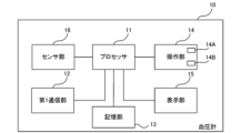
- FIG. 2 is a block diagram showing an example of the configuration of the sphygmomanometer 10 shown in FIG.
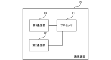
- FIG. 3 is a block diagram showing an example of the configuration of the communication device 20 shown in FIG.
- FIG. 4 is a perspective view that illustrates an example of the external appearance of the sphygmomanometer 10 illustrated in FIG. 1 and an example of the external appearance of an activity meter that is one of the measuring devices.
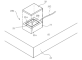
- FIG. 5 is an exploded perspective view illustrating an example of the external appearance of the communication device 20 illustrated in FIG. FIG.
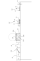
- FIG. 6 is a side view showing a state in which upper arm blood pressure monitor 10X, wrist blood pressure monitor 10Y, activity meter 10Z, and communication device 20 are placed on a placement surface 41.
- FIG. 7 is a sequence chart showing a process procedure for pairing the sphygmomanometer A with the communication device 20 when the sphygmomanometer A and the sphygmomanometer B exist as the sphygmomanometer 10.
- FIG. 8 is a schematic cross-sectional view of the communication device 20 showing a modified example of the communication antenna 22A mounted on the communication device 20. As shown in FIG.
- the system of the disclosed technique includes a measuring device including a first short-range wireless communication unit that communicates by a communication method that allows pairing, and a communication device including a second short-range wireless communication unit that communicates by a communication method that allows pairing.
- the communication device When the communication device is placed on a mounting surface, the communication device has a radio wave shielding section that is erected in a direction intersecting the mounting surface and is arranged to surround the antenna of the second short-range wireless communication section, and the distance between the mounting surface and the edge of the radio wave shielding section opposite to the mounting surface in a direction perpendicular to the mounting surface is equal to or greater than the height of the measuring device placed on the mounting surface in the direction perpendicular to the mounting surface.
- the radio wave characteristics of the communication device can be made directional toward the top of the mounting surface by the radio wave shielding section. Since the distance from the edge of the radio wave shielding section to the mounting surface is equal to or greater than the height of the measuring device placed on the mounting surface, when the communication device and the measuring device are adjacently arranged on the mounting surface, the strength of the radio wave of the measuring device received by the communication device can be reduced. On the other hand, when the measuring device is located above the communication device, the strength of the radio wave of the measuring device received by the communication device can be increased.
- each communication device performs a pairing operation with one of the multiple measurement devices in parallel, for example, by using the radio wave intensity received by the communication device, only the measurement device placed above each communication device can be identified as the pairing partner of that communication device. For example, by simply repeating the operation of placing a measurement device on each communication device and pairing with that measurement device, and when the pairing is completed, placing another measurement device on each communication device and pairing with that measurement device, all measurement devices and communication devices can be efficiently paired. As a result, information measured by multiple measurement devices can be safely and efficiently collected by the communication device and used for clinical research, etc.
- the following describes one embodiment of the system, the information analysis system 100.
- Fig. 1 is a schematic diagram showing a schematic configuration of an information analysis system 100.
- the information analysis system 100 includes a blood pressure monitor 10 as an example of a measurement device, a communication device 20, and a personal computer (PC) 30 as an example of an information terminal, and is a system for analyzing measurement data of the blood pressure monitor 10 by the PC 30.
- the information analysis system 100 is configured by a plurality of (five as an example) blood pressure monitors 10, a plurality of (two as an example) communication devices 20, and the same number of PCs 30 as the total number of the communication devices 20.
- the blood pressure monitor 10 measures blood pressure information non-invasively.
- the blood pressure monitor 10 and the communication device 20 are configured to be able to communicate with each other via short-range wireless communication.
- the short-range wireless communication method is a method that enables secure communication by performing pairing (sharing encryption information for encrypting communication), and for example, Bluetooth (registered trademark) (hereinafter referred to as BLE) can be adopted.
- BLE Bluetooth (registered trademark)
- the PC 30 and the communication device 20 are wired and connected by a cable such as a USB (Universal Serial Bus) cable, and are configured to be able to communicate with each other.
- the PC 30 and the communication device 20 may also be configured to be connected wirelessly.
- the information analysis system 100 is used, for example, in clinical research.
- a researcher conducting clinical research lends a blood pressure monitor 10 to each of multiple collaborators and has each collaborator periodically measure blood pressure information. After a certain period of time has passed, the researcher collects the blood pressure monitor 10 from each collaborator and imports the measurement data stored in the collected blood pressure monitor 10 into the PC 30 via the communication device 20.
- the PC 30 is connected to a network such as the Internet or an intranet, and the measurement data imported into the PC 30 is, for example, uploaded to a server (not shown) and managed. Note that the PC 30 is not essential to the information analysis system 100.
- the communication device 20 has a function of uploading measurement data to a server, it is also possible to configure the communication device 20 to be directly connected to the network.
- one communication device 20 is connected to one PC 30 in the configuration, multiple communication devices 20 can also be connected to one PC 30.
- multiple communication devices 20 are described, there may be only one communication device 20.
- Fig. 2 is a block diagram showing an example of the configuration of the sphygmomanometer 10 shown in Fig. 1.
- the sphygmomanometer 10 includes a processor 11, a first communication unit 12, a storage unit 13, an operation unit 14, a display unit 15, and a sensor unit 16.
- the sensor unit 16 is equipped with a pressure sensor placed in the cuff portion of the blood pressure monitor 10 as a measurement sensor, and this pressure sensor detects the pulse wave from the user's blood vessel under the appropriate cuff pressure.
- the blood pressure monitor 10 can calculate blood pressure information including the systolic blood pressure, diastolic blood pressure, and pulse rate based on the pulse wave detected by the sensor unit 16.
- the first communication unit 12 is a communication interface (here, a BLE chip) for short-range wireless communication, and includes a communication antenna and various circuits.
- a communication interface here, a BLE chip
- the storage unit 13 includes a work memory such as a RAM (Random Access Memory) as well as a non-transitory storage medium such as a flash memory.
- This storage medium stores various information such as measured blood pressure information.
- the operation unit 14 is an input means such as a button or a touch panel that accepts input from the user, and accepts various operations from the user, such as turning the power on/off, starting the measurement of blood pressure information, and selecting items.
- the operation unit 14 includes a measurement start button 14A for instructing the start of blood pressure information measurement, and a communication button 14B for activating the first communication unit 12 (enabling short-range wireless communication).
- the measurement start button 14A and the communication button 14B may be hardware buttons, or may be software buttons displayed on a display unit 15 equipped with a touch panel.
- the display unit 15 is configured with a display such as an organic EL (electroluminescence) display or a liquid crystal display, and displays the measured blood pressure information, etc.
- a display such as an organic EL (electroluminescence) display or a liquid crystal display, and displays the measured blood pressure information, etc.
- Processor 11 controls each part of blood pressure monitor 10. When processor 11 detects pressing of measurement start button 14A included in operation unit 14, it accepts an instruction to start measurement, pressurizes the cuff, and calculates blood pressure information based on the pulse wave detected by sensor unit 16 under appropriate cuff pressure. Processor 11 then causes display unit 15 to display the calculated blood pressure information. Processor 11 controls each component of blood pressure monitor 10 to execute processing according to the user's operation performed via operation unit 14.
- the processor 11 When the processor 11 detects a brief press of the communication button 14B included in the operation unit 14, it activates the first communication unit 12. When a communication connection has been established with a paired device, the processor 11 controls the transmission of measurement data stored in the memory unit 13 from the first communication unit 12 to that device. When the processor 11 detects an operation in which the communication button 14B is continuously pressed for a predetermined period of time (a so-called long press operation), it transitions the operation mode of the sphygmomanometer 10 to the pairing mode.
- the pairing mode is a mode in which a device to be paired with is detected and pairing is performed with that device.
- the blood pressure monitor 10 can be replaced with a weight scale, a body composition monitor, a pulse monitor, a heart rate monitor, a thermometer, a blood glucose meter, a pulse oximeter, an activity monitor, or the like.
- the sensor unit 16 includes various measuring sensors (pressure sensor, pulse wave sensor, blood glucose sensor, photoelectric sensor, temperature sensor, acceleration sensor, etc.) for measuring the physical quantity of the measurement target.
- the processor 11 upon detecting the pressing of the measurement start button 14A included in the operation unit 14, activates the measuring sensors (pressure sensor, pulse wave sensor, blood glucose sensor, photoelectric sensor, temperature sensor, etc.) included in the sensor unit 16 to measure bioinformation.
- the measuring device is an activity amount measuring device, when the activity amount measuring device is moved, information corresponding to the movement is output from the measuring sensors (acceleration sensor, angular velocity sensor, etc.) included in the sensor unit 16.
- FIG. 3 is a block diagram showing an example of the configuration of the communication device 20 shown in Fig. 1.
- the communication device 20 includes a processor 21, a second communication unit 22, and a third communication unit 23.
- the second communication unit 22 is a communication interface for short-range wireless communication with the sphygmomanometer 10, and includes a communication antenna (communication antenna 22A described below) and various circuits.
- the third communication unit 23 is a communication interface for performing wired communication with the PC 30.
- the processor 21 controls each part of the communication device 20.
- the processor 21 may be a CPU (Central Processing Unit), which is a general-purpose processor that executes software (programs) and performs various functions; a Programmable Logic Device (PLD), which is a processor whose circuit configuration can be changed after manufacture, such as an FPGA (Field Programmable Gate Array); or a dedicated electrical circuit, such as an ASIC (Application Specific Integrated Circuit), which is a processor having a circuit configuration designed specifically to execute specific processing.
- the processor 21 may be composed of a single processor, or may be composed of a combination of two or more processors of the same or different types (e.g., multiple FPGAs, or a combination of a CPU and an FPGA). More specifically, the hardware structure of the processor 21 is an electrical circuit (circuitry) that combines circuit elements such as semiconductor elements.
- a blood pressure monitor 10 used in the information analysis system 100 shown in FIG. 1 is a type of blood pressure monitor in which the user wraps and fastens a cuff around a part to be measured, and so-called arm-in type blood pressure monitors are excluded.
- FIG. 4 is a perspective view showing an example of the external appearance of the blood pressure monitor 10 shown in FIG. 1 and an example of the external appearance of an activity monitor, which is one of the measuring devices.
- an upper arm type blood pressure monitor 10X and a wrist type blood pressure monitor 10Y are shown as blood pressure monitors 10.
- the upper arm type blood pressure monitor 10X includes a main body 17 including a display unit 15, an operation unit 14, and a processor 11 (not shown), a cuff 19 that is wrapped around and fixed to the upper arm, and an air tube 18 that connects the main body 17 and the cuff 19.
- the state in which the main body 17 is placed on a flat mounting surface so that the information displayed on the display unit 15 can be confirmed from above the mounting surface is defined as the standard mounting state of the upper arm type blood pressure monitor 10X.
- the wrist-type blood pressure monitor 10Y includes a main body 17 including a display unit 15, an operation unit 14, and a processor 11 (not shown), and a cuff 19 that is wrapped around and fixed to the wrist.
- the standard placement state of the wrist-type blood pressure monitor 10Y is defined as the state in which the main body 17 and cuff 19 are placed on a flat placement surface so that the information displayed on the display unit 15 can be confirmed from above the surface.
- FIG. 4 shows activity meter 10Z.
- Activity meter 10Z has only a portion equivalent to main body 17 of blood pressure monitor 10, and has a rectangular parallelepiped outer shape.
- the state in which activity meter 10Z is placed on a flat surface so that the information displayed on display unit 15 can be confirmed from above the surface is referred to as the standard placement state of activity meter 10Z.
- FIG. 5 is a perspective view showing a schematic example of the appearance of the communication device 20 shown in Fig. 1.
- the communication device 20 includes a main body 20M having a rectangular parallelepiped shape and a cable 20C connected to the main body 20M, and is used by placing the main body 20M on a placement surface 41 (flat surface) which is the surface of a desk 40.
- the main body 20M has a rectangular parallelepiped shape, but is not limited thereto and may have other shapes.
- the main body 20M may be cylindrical.
- the main body 20M comprises a body 24 having a recess 25 on the surface opposite to the support surface 41 (hereinafter referred to as the bottom surface) that faces the support surface 41 when placed on the support surface 41, and a flat lid 26 that covers the recess 25 of the body 24, and the lid 26 is fixed to the top surface of the body 24.
- the main body 24 includes the processor 21, second communication unit 22, and third communication unit 23 shown in FIG. 3.
- the recess 25 is provided with a communication antenna 22A included in the second communication unit 22.
- the communication antenna 22A is configured with a dipole antenna, a monopole antenna, an inverted F antenna, a loop antenna, a Yagi antenna, or the like. It is preferable that the communication antenna 22A is configured such that, when the main body 24 is placed on the placement surface 41 as shown in FIG. 5, the radio wave strength in a direction perpendicular to the placement surface 41 and away from the placement surface 41 is greater than the radio wave strength in any other direction (i.e., the communication antenna 22A has directivity toward the top of the placement surface 41).
- the recess 25 is provided with a radio wave shielding section 25A that is erected in a direction that intersects with the placement surface 41 (orthogonal in the example of FIG. 5) and is arranged to surround the communication antenna 22A.
- a rectangular plate-shaped radio wave shielding section 25B is provided on the bottom surface of the recess 25, and the communication antenna 22A is arranged on top of the radio wave shielding section 25B.
- the radio wave shielding section 25A has a rectangular frame shape that rises vertically from the periphery of the radio wave shielding section 25B.
- the radio wave shielding section 25A and the radio wave shielding section 25B are each made of a shielding material that can shield radio waves emitted from the communication antenna 22A.
- the shielding material is made of a material that absorbs or reflects radio waves, or that absorbs and reflects radio waves.
- FIG. 6 is a side view showing the upper arm blood pressure monitor 10X, wrist blood pressure monitor 10Y, activity meter 10Z, and communication device 20 placed on a mounting surface 41.
- the area shown by the dashed dotted line in the figure shows the radio wave characteristics of the communication device 20, which has directionality toward the upper side of the mounting surface 41 as shown.
- FIG. 6 shows the distance L1 between the upper edge (edge opposite to the mounting surface 41) of the radio wave shielding portion 25A of the communication device 20 and the mounting surface 41 in a direction perpendicular to the mounting surface 41. Also shown in FIG. 6 are the height L2 of the main body 17 of the upper arm type blood pressure monitor 10X in the standard mounting state (the distance between the mounting surface 41 and the part of the main body 17 farthest from the mounting surface 41 in the direction perpendicular to the mounting surface 41), the height L3 of the wrist type blood pressure monitor 10Y in the standard mounting state (the distance between the mounting surface 41 and the part farthest from the mounting surface 41 in the direction perpendicular to the mounting surface 41), and the height L4 of the activity meter 10Z in the standard mounting state (the distance between the mounting surface 41 and the part farthest from the mounting surface 41 in the direction perpendicular to the mounting surface 41).
- the magnitude relationship between the heights L2, L3, and L4 is L2>L3>L4.
- Distance L1 in communication device 20 is equal to or greater than height L2 of upper arm blood pressure monitor 10X, which is the tallest measurement device in the standard placement state.
- height L2 is at most approximately 300 mm.
- height L4 is at most approximately 15 mm. Therefore, if an activity meter or blood pressure monitor is assumed as the measurement device used in information analysis system 100, distance L1 may be set in the range of 15 mm to 300 mm.
- the antennas of the first communication units 12 of the upper arm blood pressure monitor 10X, wrist blood pressure monitor 10Y, and activity monitor 10Z are omnidirectional. Since the distance L1 is equal to or greater than the height L2, even if the measurement device (upper arm blood pressure monitor 10X, wrist blood pressure monitor 10Y, or activity monitor 10Z) is placed near the communication device 20 on the placement surface 41, the components of the radio waves radiated from the measurement device in the direction along the placement surface 41 are blocked by the radio wave shielding unit 25B. This makes it possible to weaken the strength of the radio waves radiated from the measurement device placed nearby and received by the communication device 20. On the other hand, when the measurement device is placed on the cover 26, the strength of the radio waves radiated from the measurement device and received by the communication device 20 can be increased.
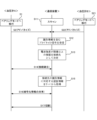
- Fig. 7 is a sequence chart showing a processing procedure for pairing the sphygmomanometer A with a specific communication device 20 when a sphygmomanometer A and a sphygmomanometer B exist as the sphygmomanometer 10.
- the processor 21 of that communication device 20 starts scanning using the second communication unit 22.
- Scanning means that the second communication unit 22 goes into a receiving state and acquires information about nearby devices.
- the researcher turns on the power of blood pressure monitor A and blood pressure monitor B placed on the placement surface 41, and then presses and holds the communication button 14B included in the operation unit 14 of each blood pressure monitor to switch each blood pressure monitor to pairing mode (steps S1 and S21). The researcher then places blood pressure monitor A on the lid 26 of the specific communication device 20.
- the processors 11 of blood pressure monitor A and blood pressure monitor B transition to the pairing mode, they activate the first communication unit 12 and start advertising by the first communication unit 12 (steps S2 and S22).
- Advertising refers to broadcasting a packet including various information.
- a signal transmitted by advertising is referred to as a broadcast signal.
- This information includes identification information of the blood pressure monitor 10 (e.g., unique address information of the first communication unit 12, etc.).
- the identification information of the blood pressure monitor 10 and authentication information required for mutual authentication between the blood pressure monitor 10 and another device e.g., a six-digit number, etc.
- the identification information of the blood pressure monitor 10 and authentication information required for mutual authentication between the blood pressure monitor 10 and another device are associated with each other and are stored in advance in a storage unit of a server or the like connected to the network.
- the processor 21 of the communication device 20 receives the broadcast signal transmitted from sphygmomanometer A and the broadcast signal transmitted from sphygmomanometer B (step S12), it determines, as the connection partner, one of sphygmomanometer A and sphygmomanometer B whose broadcast signal has a radio wave strength equal to or greater than the threshold (step S13).
- the radio wave strength of sphygmomanometer A's broadcast signal is equal to or greater than the threshold, and the radio wave strength of sphygmomanometer B's broadcast signal is less than the threshold. Therefore, sphygmomanometer A is determined as the connection partner.
- step S13 it is preferable to determine, as the connection partner, the device whose broadcast signal has a radio wave strength equal to or greater than the threshold and is at its maximum.
- the processor 21 of the communication device 20 establishes a communication connection with the blood pressure monitor A (step S14).
- the processor 21 accesses the server via the PC 30 and searches for authentication information corresponding to the identification information included in the broadcast signal received from the blood pressure monitor A in step S12. If the authentication information exists in the server, the processor 21 acquires the authentication information from the server (step S15) and completes mutual authentication with the blood pressure monitor A using the acquired authentication information.
- the processor 21 then shares encrypted information with the blood pressure monitor A for performing encrypted communication by short-range wireless communication (step S16). Sharing encrypted information means that the processor 11 of the blood pressure monitor A generates encrypted information, stores the encrypted information in the storage unit 13 and transmits the encrypted information to the communication device 20, and the processor 21 of the communication device 20 stores the encrypted information.
- the processor 21 may generate encrypted information, store the encrypted information, and transmit the encrypted information to the blood pressure monitor A, and the blood pressure monitor A may store the encrypted information in the storage unit 13, thereby sharing encrypted information.
- the processor 21 then disconnects the communication connection with sphygmomanometer A (step S17). Thereafter, secure communication using encrypted information becomes possible between the communication device 20 and sphygmomanometer A. Next, the researcher places sphygmomanometer A on the placement surface 41, and instead places sphygmomanometer B on the specific communication device 20. This causes the processing from step S14 to step S17 to be carried out between this communication device 20 and sphygmomanometer B.
- a researcher can easily complete pairing of a blood pressure monitor 10 with the communication device 20 by simply placing the blood pressure monitor 10 to be paired on the communication device 20. Even in a situation where blood pressure monitor A is placed on the communication device 20 and blood pressure monitor B is placed on the placement surface 41, the effect of the radio wave shielding portion 25A prevents the communication device 20 from determining blood pressure monitor B as the connection destination. Only the blood pressure monitor 10 placed on the communication device 20 can be paired with that communication device 20, so that the task of pairing each of the multiple blood pressure monitors 10 with the communication device 20 can be performed efficiently.
- FIG. 8 is a schematic cross-sectional view of the communication device 20 showing a modified example of the communication antenna 22A mounted on the communication device 20.
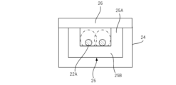
- the communication antenna 22A shown in FIG. 8 is configured by arranging a leaky coaxial cable in a ring shape on the radio wave shielding portion 25B.
- the leaky coaxial cable radiates radio waves only in the vicinity of its axis. Therefore, as shown by the dashed line in FIG. 8, the radiation range of the radio waves from the communication antenna 22A can be limited to, for example, the inside of the recess 25 and its vicinity.
- the reception strength of radio waves from measurement devices other than the measurement device placed on the communication device 20 can be significantly reduced. Therefore, the pairing partner of the communication device 20 can be easily limited to the measurement device placed on the communication device 20, and the pairing operation can be performed efficiently.
Landscapes
- Engineering & Computer Science (AREA)
- Health & Medical Sciences (AREA)
- Life Sciences & Earth Sciences (AREA)
- Computer Networks & Wireless Communication (AREA)
- Biomedical Technology (AREA)
- Signal Processing (AREA)
- Computer Security & Cryptography (AREA)
- Cardiology (AREA)
- General Health & Medical Sciences (AREA)
- Medical Informatics (AREA)
- Public Health (AREA)
- Molecular Biology (AREA)
- Heart & Thoracic Surgery (AREA)
- Veterinary Medicine (AREA)
- Animal Behavior & Ethology (AREA)
- Physiology (AREA)
- Physics & Mathematics (AREA)
- Surgery (AREA)
- Biophysics (AREA)
- Pathology (AREA)
- Primary Health Care (AREA)
- Business, Economics & Management (AREA)
- General Business, Economics & Management (AREA)
- Epidemiology (AREA)
- Vascular Medicine (AREA)
- Pulmonology (AREA)
- Measuring Pulse, Heart Rate, Blood Pressure Or Blood Flow (AREA)
- Measuring And Recording Apparatus For Diagnosis (AREA)
- Medical Treatment And Welfare Office Work (AREA)
Abstract
Description
ペアリングが可能な通信方式による通信を行う第1近距離無線通信部(第1通信部12)を含む測定装置(血圧計10、活動量計10Z)と、ペアリングが可能な通信方式による通信を行う第2近距離無線通信部(第2通信部22)を含む通信装置(通信装置20)と、を有するシステム(情報分析システム100)であって、
上記通信装置は、載置面(載置面41)に載置された状態において、上記載置面に交差する方向に立設され且つ上記第2近距離無線通信部のアンテナ(通信アンテナ22A)を囲んで配置された電波遮蔽部(電波遮蔽部25A)を有し、
上記載置面に直交する方向における上記電波遮蔽部の上記載置面側と反対側の端縁と上記載置面との距離(距離L1)は、上記載置面に載置された上記測定装置の上記方向における高さ(高さL2)以上となっている、システム。
(1)に記載のシステムであって、
上記アンテナは、漏洩同軸ケーブルを含んで構成される、システム。
(1)又は(2)に記載のシステムであって、
上記通信装置は、プロセッサ(プロセッサ21)を含み、
上記プロセッサは、上記第2近距離無線通信部によってブロードキャスト信号を受信した場合には、そのブロードキャスト信号の送信元の上記測定装置のうち、近距離無線通信の電波強度が閾値以上となる上記測定装置との間でペアリングの処理を行う、システム。
(3)に記載のシステムであって、
上記プロセッサは、上記ペアリングの対象となる上記測定装置の識別情報を取得し、上記識別情報に対応する認証情報を記憶部から取得できた場合に、その測定装置との間で暗号化情報の共有を行う、システム。
ペアリングが可能な通信方式による通信を行う近距離無線通信部(第2通信部22)を含む通信装置(通信装置20)であって、
プロセッサ(プロセッサ21)を備え、
上記近距離無線通信部のアンテナ(通信アンテナ22A)は、上記通信装置が載置面(載置面41)に載置された状態において、上記載置面に直交する方向に指向性を持ち、
上記プロセッサは、上記近距離無線通信部によってブロードキャスト信号を受信した場合には、そのブロードキャスト信号の送信元の装置のうち、近距離無線通信の電波強度が閾値以上となる装置との間でペアリングの処理を行い、
その処理において、上記プロセッサは、上記ペアリングの対象となる上記装置の識別情報を取得し、上記識別情報に対応する認証情報を記憶部から取得できた場合に、その装置との間で暗号化情報の共有を行う、通信装置。
ペアリングが可能な通信方式による通信を行う近距離無線通信部(第2通信部22)と、
載置面(載置面41)に載置された状態において、上記載置面に交差する方向に立設され且つ上記近距離無線通信部のアンテナ(通信アンテナ22A)を囲んで配置された電波遮蔽部(電波遮蔽部25A)と、を備え、
上記載置面に直交する方向における上記電波遮蔽部の上記載置面側と反対側の端縁と上記載置面との距離(距離L1)は、15mm以上300mm以下となっている、通信装置。
本開示の技術のシステムは、ペアリングが可能な通信方式による通信を行う第1近距離無線通信部を含む測定装置と、ペアリングが可能な通信方式による通信を行う第2近距離無線通信部を含む通信装置と、を有するものである。通信装置は、載置面に載置された状態において、載置面に交差する方向に立設され且つ第2近距離無線通信部のアンテナを囲んで配置された電波遮蔽部を有し、載置面に直交する方向における電波遮蔽部の載置面側と反対側の端縁と載置面との距離は、載置面に載置された測定装置の前記方向における高さ以上となっている。このような構成により、通信装置の電波特性を、電波遮蔽部によって、載置面の上方へ指向性を持つものとすることができる。この電波遮蔽部の端縁から載置面までの距離が、当該載置面に載置された測定装置の高さ以上となっていることで、通信装置と測定装置が載置面において隣接配置されている状況では、通信装置で受信されるその測定装置の電波の強度を小さくすることができる。一方、通信装置の上方に測定装置が位置している状況では、通信装置で受信されるその測定装置の電波の強度を大きくすることができる。このため、複数の通信装置と複数の測定装置とを同じ載置面に載置し、各通信装置によって、この複数の測定装置のいずれかとペアリングする作業を並行して行う状況であっても、例えば、通信装置で受信される電波強度を利用することで、各通信装置の上方に配置された測定装置だけを、その通信装置のペアリング相手として特定できる。例えば、各通信装置の上に測定装置を載置して該測定装置とのペアリングを行い、そのペアリングが終了したら、別の測定装置を各通信装置の上に載置して該測定装置とのペアリングを行う、といった作業を繰り返し行うだけで、全ての測定装置と通信装置とのペアリングを効率的に行うことができる。これにより、複数の測定装置で測定された情報を通信装置によって安全かつ効率的に収集して、臨床研究などに役立てることができる。
図1は、情報分析システム100の概略構成を示す模式図である。情報分析システム100は、測定装置の一例である血圧計10と、通信装置20と、情報端末の一例であるパーソナルコンピュータ(PC)30と、を備え、血圧計10の測定データ等をPC30で分析するためのシステムである。図1の例では、複数(一例として5つ)の血圧計10と、複数(一例として2つ)の通信装置20と、通信装置20の総数と同じ数のPC30と、により、情報分析システム100が構成されている。血圧計10は、非侵襲的に血圧情報を測定するものである。
図2は、図1に示す血圧計10の構成の一例を示すブロック図である。血圧計10は、プロセッサ11と、第1通信部12と、記憶部13と、操作部14と、表示部15と、センサ部16と、を備える。
図3は、図1に示す通信装置20の構成の一例を示すブロック図である。通信装置20は、プロセッサ21と、第2通信部22と、第3通信部23と、を備える。
図1に示す情報分析システム100にて利用される血圧計10は、被測定部位へのカフの巻き付け及び固定をユーザが行うタイプの血圧計であり、いわゆるアームインタイプの血圧計は除外される。
図5は、図1に示す通信装置20の外観の一例を模式的に示す斜視図である。通信装置20は、直方体形状の主体部20Mと、主体部20Mに接続されたケーブル20Cと、を備え、主体部20Mを机40の表面である載置面41(平面)に載置して利用される。主体部20Mは直方体形状としているが、これに限定されるものではなく、その他の形状とすることもできる。例えば、主体部20Mは、円柱状であってもよい。
次に、血圧計10と通信装置20のペアリング方法について説明する。図7は、血圧計10として血圧計Aと血圧計Bが存在している場合に、血圧計Aと特定の通信装置20とをペアリングする際の処理の手順を示すシーケンスチャートである。
10X 上腕式血圧計
10Y 手首式血圧計
10Z 活動量計
11 プロセッサ
12 第1通信部
13 記憶部
14 操作部
14A 測定開始ボタン
14B 通信ボタン
15 表示部
16 センサ部
17,20M 主体部
18 エアチューブ
19 カフ
20 通信装置
20C ケーブル
21 プロセッサ
22 第2通信部
22A 通信アンテナ
23 第3通信部
24 本体部
25 凹部
25A,25B 電波遮蔽部
26 蓋部
30 パーソナルコンピュータ
40 机
41 載置面
100 情報分析システム
L1 距離
L2、L3、L4 高さ
Claims (6)
- ペアリングが可能な通信方式による通信を行う第1近距離無線通信部を含む測定装置と、ペアリングが可能な通信方式による通信を行う第2近距離無線通信部を含む通信装置と、を有するシステムであって、
前記通信装置は、載置面に載置された状態において、前記載置面に交差する方向に立設され且つ前記第2近距離無線通信部のアンテナを囲んで配置された電波遮蔽部を有し、
前記載置面に直交する方向における前記電波遮蔽部の前記載置面側と反対側の端縁と前記載置面との距離は、前記載置面に載置された前記測定装置の前記方向における高さ以上となっている、システム。 - 請求項1に記載のシステムであって、
前記アンテナは、漏洩同軸ケーブルを含んで構成される、システム。 - 請求項1又は2に記載のシステムであって、
前記通信装置は、プロセッサを含み、
前記プロセッサは、前記第2近距離無線通信部によってブロードキャスト信号を受信した場合には、当該ブロードキャスト信号の送信元の前記測定装置のうち、近距離無線通信の電波強度が閾値以上となる前記測定装置との間でペアリングの処理を行う、システム。 - 請求項3に記載のシステムであって、
前記プロセッサは、前記ペアリングの対象となる前記測定装置の識別情報を取得し、前記識別情報に対応する認証情報を記憶部から取得できた場合に、当該測定装置との間で暗号化情報の共有を行う、システム。 - ペアリングが可能な通信方式による通信を行う近距離無線通信部を含む通信装置であって、
プロセッサを備え、
前記近距離無線通信部のアンテナは、前記通信装置が載置面に載置された状態において、前記載置面に直交する方向に指向性を持ち、
前記プロセッサは、前記近距離無線通信部によってブロードキャスト信号を受信した場合には、当該ブロードキャスト信号の送信元の装置のうち、近距離無線通信の電波強度が閾値以上となる装置との間でペアリングの処理を行い、
当該処理において、前記プロセッサは、前記ペアリングの対象となる前記装置の識別情報を取得し、前記識別情報に対応する認証情報を記憶部から取得できた場合に、当該装置との間で暗号化情報の共有を行う、通信装置。 - ペアリングが可能な通信方式による通信を行う近距離無線通信部と、
載置面に載置された状態において、前記載置面に交差する方向に立設され且つ前記近距離無線通信部のアンテナを囲んで配置された電波遮蔽部と、を備え、
前記載置面に直交する方向における前記電波遮蔽部の前記載置面側と反対側の端縁と前記載置面との距離は、15mm以上300mm以下となっている、通信装置。
Priority Applications (3)
| Application Number | Priority Date | Filing Date | Title |
|---|---|---|---|
| DE112024000831.3T DE112024000831T5 (de) | 2023-06-07 | 2024-01-12 | System und kommunikationsvorrichtung |
| CN202480026660.9A CN121058344A (zh) | 2023-06-07 | 2024-01-12 | 系统以及通信装置 |
| US19/363,149 US20260046963A1 (en) | 2023-06-07 | 2025-10-20 | System and communication device |
Applications Claiming Priority (2)
| Application Number | Priority Date | Filing Date | Title |
|---|---|---|---|
| JP2023093951A JP2024175875A (ja) | 2023-06-07 | 2023-06-07 | システム及び通信装置 |
| JP2023-093951 | 2023-06-07 |
Related Child Applications (1)
| Application Number | Title | Priority Date | Filing Date |
|---|---|---|---|
| US19/363,149 Continuation US20260046963A1 (en) | 2023-06-07 | 2025-10-20 | System and communication device |
Publications (1)
| Publication Number | Publication Date |
|---|---|
| WO2024252710A1 true WO2024252710A1 (ja) | 2024-12-12 |
Family
ID=93795230
Family Applications (1)
| Application Number | Title | Priority Date | Filing Date |
|---|---|---|---|
| PCT/JP2024/000652 Ceased WO2024252710A1 (ja) | 2023-06-07 | 2024-01-12 | システム及び通信装置 |
Country Status (5)
| Country | Link |
|---|---|
| US (1) | US20260046963A1 (ja) |
| JP (1) | JP2024175875A (ja) |
| CN (1) | CN121058344A (ja) |
| DE (1) | DE112024000831T5 (ja) |
| WO (1) | WO2024252710A1 (ja) |
Citations (6)
| Publication number | Priority date | Publication date | Assignee | Title |
|---|---|---|---|---|
| JPH0730325A (ja) * | 1993-07-08 | 1995-01-31 | Canon Inc | 無指向性アンテナの電波遮蔽装置 |
| JP2012205025A (ja) * | 2011-03-25 | 2012-10-22 | Casio Comput Co Ltd | 感度調整装置及び電波通信機器 |
| JP2018088573A (ja) * | 2016-11-28 | 2018-06-07 | 住友電気工業株式会社 | ペアリング方法、通信装置、ペアリング装置、子機パッケージおよび製造方法 |
| JP2018527054A (ja) * | 2015-07-16 | 2018-09-20 | コーニンクレッカ フィリップス エヌ ヴェKoninklijke Philips N.V. | モバイル超音波システムとの無線超音波プローブのペアリング |
| US20210350918A1 (en) * | 2020-05-07 | 2021-11-11 | Dexcom, Inc. | Secure health management system |
| JP2022551564A (ja) * | 2019-10-14 | 2022-12-12 | ティージェイ スミス アンド ネフュー リミテッド | 創傷療法デバイスとペアリングするためのシステムおよび方法 |
-
2023
- 2023-06-07 JP JP2023093951A patent/JP2024175875A/ja active Pending
-
2024
- 2024-01-12 CN CN202480026660.9A patent/CN121058344A/zh active Pending
- 2024-01-12 DE DE112024000831.3T patent/DE112024000831T5/de active Pending
- 2024-01-12 WO PCT/JP2024/000652 patent/WO2024252710A1/ja not_active Ceased
-
2025
- 2025-10-20 US US19/363,149 patent/US20260046963A1/en active Pending
Patent Citations (6)
| Publication number | Priority date | Publication date | Assignee | Title |
|---|---|---|---|---|
| JPH0730325A (ja) * | 1993-07-08 | 1995-01-31 | Canon Inc | 無指向性アンテナの電波遮蔽装置 |
| JP2012205025A (ja) * | 2011-03-25 | 2012-10-22 | Casio Comput Co Ltd | 感度調整装置及び電波通信機器 |
| JP2018527054A (ja) * | 2015-07-16 | 2018-09-20 | コーニンクレッカ フィリップス エヌ ヴェKoninklijke Philips N.V. | モバイル超音波システムとの無線超音波プローブのペアリング |
| JP2018088573A (ja) * | 2016-11-28 | 2018-06-07 | 住友電気工業株式会社 | ペアリング方法、通信装置、ペアリング装置、子機パッケージおよび製造方法 |
| JP2022551564A (ja) * | 2019-10-14 | 2022-12-12 | ティージェイ スミス アンド ネフュー リミテッド | 創傷療法デバイスとペアリングするためのシステムおよび方法 |
| US20210350918A1 (en) * | 2020-05-07 | 2021-11-11 | Dexcom, Inc. | Secure health management system |
Also Published As
| Publication number | Publication date |
|---|---|
| JP2024175875A (ja) | 2024-12-19 |
| US20260046963A1 (en) | 2026-02-12 |
| DE112024000831T5 (de) | 2025-12-24 |
| CN121058344A (zh) | 2025-12-02 |
Similar Documents
| Publication | Publication Date | Title |
|---|---|---|
| US20240122540A1 (en) | Systems and Methods of Spatial Filtering for Measuring Electrical Signals | |
| US10869599B2 (en) | Remote monitoring of analyte measurements | |
| US10786169B2 (en) | Bio-processor for measuring each biological signals and wearable device having the same | |
| US20080208009A1 (en) | Wearable Device, System and Method for Measuring Vital Parameters | |
| CN108289616B (zh) | 使用人体通信发送/接收健康信息的方法和装置 | |
| US20120316413A1 (en) | Measurement apparatus | |
| CN116744846A (zh) | 具有多个光学传感器的电子设备及其控制方法 | |
| KR102173725B1 (ko) | 생체 신호를 측정하는 방법 및 장치 | |
| US20230210392A1 (en) | Physiological Sensing Patch for Coupling a Device to a Body of a User | |
| CN117396974A (zh) | 用于医疗保健的电子装置及其运行方法 | |
| CN114711734A (zh) | 测量生理参数的方法及电子设备 | |
| KR20180114495A (ko) | 전자 장치, 전자 장치 시스템, 정보 처리 방법 및 정보 프롬프트 방법 | |
| EP4410220A1 (en) | Wearable device and method for providing service on basis of user body temperature | |
| JP2024175875A (ja) | システム及び通信装置 | |
| EP3901958A1 (en) | Method for providing service on basis of genetic information on user group, and electronic device therefor | |
| US20230074565A1 (en) | Electronic device and method for detecting tremor in electronic device | |
| JP2024044702A (ja) | 測定装置、情報端末、及び情報端末の作動プログラム | |
| JP2024044702A5 (ja) | ||
| KR20230007152A (ko) | 전자 장치 및 전자 장치에서 사용자 컨텍스트 기반 산소 포화도 측정 방법 | |
| US20260046958A1 (en) | Measuring device | |
| US12533026B2 (en) | Electronic device and method of measuring oxygen saturation based on user context in the electronic device | |
| US20250049395A1 (en) | Apparatus, system, and method for remote vital sign collection | |
| CN113741779B (zh) | 设备连接方法、装置、移动测量设备和存储介质 | |
| EP4152720A1 (en) | Data transmission method and electronic device supporting same | |
| JP2024175875A5 (ja) |
Legal Events
| Date | Code | Title | Description |
|---|---|---|---|
| 121 | Ep: the epo has been informed by wipo that ep was designated in this application |
Ref document number: 24817477 Country of ref document: EP Kind code of ref document: A1 |
|
| WWE | Wipo information: entry into national phase |
Ref document number: 202517091577 Country of ref document: IN |
|
| WWE | Wipo information: entry into national phase |
Ref document number: 112024000831 Country of ref document: DE |
|
| WWP | Wipo information: published in national office |
Ref document number: 202517091577 Country of ref document: IN |
|
| WWP | Wipo information: published in national office |
Ref document number: 112024000831 Country of ref document: DE |
|
| 122 | Ep: pct application non-entry in european phase |
Ref document number: 24817477 Country of ref document: EP Kind code of ref document: A1 |