WO2024252615A1 - 物体認識装置、物体認識方法および物体認識プログラム - Google Patents
物体認識装置、物体認識方法および物体認識プログラム Download PDFInfo
- Publication number
- WO2024252615A1 WO2024252615A1 PCT/JP2023/021343 JP2023021343W WO2024252615A1 WO 2024252615 A1 WO2024252615 A1 WO 2024252615A1 JP 2023021343 W JP2023021343 W JP 2023021343W WO 2024252615 A1 WO2024252615 A1 WO 2024252615A1
- Authority
- WO
- WIPO (PCT)
- Prior art keywords
- object recognition
- inference
- likelihood
- distribution
- simulation environment
- Prior art date
- Legal status (The legal status is an assumption and is not a legal conclusion. Google has not performed a legal analysis and makes no representation as to the accuracy of the status listed.)
- Ceased
Links
Images




Classifications
-
- G—PHYSICS
- G06—COMPUTING OR CALCULATING; COUNTING
- G06T—IMAGE DATA PROCESSING OR GENERATION, IN GENERAL
- G06T7/00—Image analysis
Definitions
- the present invention relates to an object recognition device, an object recognition method, and an object recognition program.
- spatial object recognition the position and orientation of a specific object (human, vehicle, etc.) is inferred using a bounding box based on data acquired from optical cameras and LiDAR (Light Detection and Ranging). The results of this inference are then used to control work robots and monitor operations in logistics warehouses and outdoor civil engineering work sites.
- LiDAR Light Detection and Ranging
- training a recognition model generally requires a large amount of annotated (bounding box) datasets for each domain, which means that a large amount of annotated (bounding box) datasets in the field environment where the results of object recognition can be utilized is required.
- the object recognition results themselves do not provide information on the amount of error.
- the expected error value can be used to determine whether the inference is likely to have the accuracy required for estimating and controlling collision risk, so in applications of object recognition results, not only the inference value but also information on the reliability of the inference (expected error value) is required.
- Non-Patent Document 1 points out the discrepancy between the confidence score and the actual likelihood in image classification AI (Artificial Intelligence), and proposes a method to adjust the variance of the confidence score by applying a temperature parameter when applying softmax to the NN output (logit) as a method to correct the bias.
- Non-Patent Document 2 specifies and evaluates a method of calibration using multidimensional detection results (position, box size, object type) to define the likelihood as the probability that the inferred bounding box and ground truth are within a specific IOU threshold, and proposes calibration of the confidence score of two-dimensional object recognition AI.
- the degree of deviation is essentially a continuous quantity, but in the object detection task in Non-Patent Document 2, the calibration is for a binary inference of correct/incorrect, and additional data is required to estimate the parameters of the calibration function.
- the object of the present invention is to provide an object recognition device, an object recognition method, and an object recognition program that contribute to providing an evaluation of the error (variation) in the inference value (object position/orientation confidence score) of an object recognition AI.
- an object recognition device in a first aspect of the present invention, includes an error distribution information collection unit that executes a trained object recognition AI in a simulation environment and accumulates a distribution of inference values from inference results including a confidence score, and a likelihood calculation unit that calculates the likelihood of an inference result sequence at each position and orientation from the distribution of inference values accumulated for each object position and orientation by execution of the object recognition AI in the simulation environment and the inference result sequence of the object recognition AI in the real environment.
- an object recognition method in which a trained object recognition AI is executed in a simulation environment, a distribution of inference values is accumulated from inference results including a confidence score, and the likelihood of an inference result sequence at each position and orientation is calculated from the distribution of inference values accumulated for each object position and orientation by execution of the object recognition AI in the simulation environment and the inference result sequence of the object recognition AI in the real environment.
- a third aspect of the present invention provides an object recognition program that causes an information processing device to execute a process of running a trained object recognition AI in a simulation environment, accumulating a distribution of inference values from inference results including a confidence score, and calculating the likelihood of the inference result sequence at each position and posture from the distribution of inference values accumulated for each object position and posture by executing the object recognition AI in the simulation environment and the inference result sequence of the object recognition AI in the real environment.
- the program can be recorded on a computer-readable storage medium.
- the storage medium can be a non-transient medium such as a semiconductor memory, a hard disk, a magnetic recording medium, an optical recording medium, etc.
- the present invention can also be embodied as a computer program product.
- an object recognition device an object recognition method, and an object recognition program that contribute to providing an evaluation of the error (variation) in the inference value (object position/orientation confidence score) of the object recognition AI.
- FIG. 1 is a functional block diagram of an object recognition device according to a first embodiment.
- FIG. 2 is a diagram showing an example of a sample space.
- FIG. 3 is a diagram showing an example of inference values of object recognition performed on a sample space.
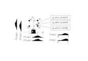
- FIG. 4 is a diagram showing an example of the distribution of inferred values p i obtained in a real environment.
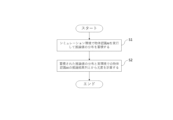
- FIG. 5 is a flowchart showing the procedure of the object recognition method according to the first embodiment.
- FIG. 6 is a functional block diagram of an object recognition device according to the second embodiment.
- FIG. 7 is a flowchart showing the procedure of the object recognition method according to the second embodiment.
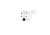
- FIG. 8 is a diagram illustrating an example of visualization of a likelihood map in the second embodiment.
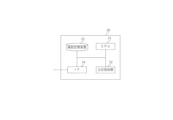
- FIG. 9 is a diagram illustrating an example of a hardware configuration of an object recognition device used in the embodiment.
- FIG. 1 is a functional block diagram of an object recognition device according to the first embodiment.
- the object recognition device 10 includes a simulation environment 11, an emulator 12, an object recognition AI 13, an error distribution information collection unit 14, an inference value data storage unit 15, a real environment sensor 16, and a likelihood calculation unit 17.
- the simulation environment 11 is a virtual representation of the real environment to which the object recognition device 10 is applied, and can be constructed, for example, by discretizing each element of a spatial vector and combining them. Note that the more finely each element is discretized, the higher the approximation accuracy will be, but it is preferable to appropriately limit the number of elements in consideration of the calculation load.
- the emulator 12 is a program that mimics the characteristics of the real environment sensor 16.
- the real environment sensor 16 may contain errors or bias when detecting data from the real environment, and this error or bias can cause errors in the inference results of the object recognition AI 13.
- the emulator 12 mimics the characteristics of the real environment sensor 16 that cause errors, making it possible to obtain information on errors caused by the characteristics of the real environment sensor 16 even when the object recognition AI 13 is executed in the simulation environment 11.
- the emulator 12 can be implemented as a program separate from the simulation environment 11, but it can also be implemented as part of the simulation environment 11.
- the object recognition AI 13 is an artificial intelligence that uses detection data for a space as input to estimate the position and posture of objects present within that space, as well as the type of object.
- the detection data used for input can be, for example, images or videos, but it can also use the output of LiDAR (Light Detection And Ranging) technology, which shines laser light and measures the distance to an object and the shape of the object based on the information of the reflected light.
- LiDAR Light Detection And Ranging
- the error distribution information collection unit 14 runs the trained object recognition AI 13 in the simulation environment 11, and estimates and accumulates the distribution of inference values from the inference results, including the confidence score.
- the inference values acquired by the error distribution information collection unit 14 are accumulated in the inference value data storage unit 15 together with the true positions and orientations of objects constructed in the simulation environment 11.
- the real environment sensor 16 is a sensor that detects spatial information of the real environment to which the object recognition device 10 is applied, and can be, for example, a device that combines an optical device with an imaging element such as a CMOS, or a LiDAR device that emits laser light and measures the distance to an object and the shape of the object based on information from the reflected light.
- CMOS complementary metal-oxide-semiconductor
- LiDAR device that emits laser light and measures the distance to an object and the shape of the object based on information from the reflected light.
- the likelihood calculation unit 17 calculates the likelihood of the inference result sequence for each position and orientation from the distribution of inference values accumulated for each position and orientation of the object by the execution of the object recognition AI 13 in the simulation environment 11 and the inference result sequence of the object recognition AI 13 in the real environment.
- the likelihood refers to the likelihood of the value of a parameter such as a model or distribution that explains an observed value when the observed value is given. In this case, it means the likelihood of the position and orientation of the object that explains the inference value from the inference result of the object recognition AI 13.
- the inference result of the object recognition AI 13 may correctly infer the true position and orientation of the object, but due to the influence of errors contained in the data acquired by the real environment sensor 16 or the imperfection of the object recognition AI 13, an inference value different from the true position and orientation of the object may be obtained.
- the likelihood calculation unit 17 calculates the likelihood to calculate the position and orientation of the object that explains the inference value from the inference result of the object recognition AI 13.
- the object recognition device 10 can provide error information for the inference value (object position/orientation confidence score) of the object recognition AI 13. In other words, by adding likelihood information to the inference value of the object recognition AI 13 and providing it, the object recognition device 10 can utilize the inference value taking into account the influence of errors contained in the object recognition.
- p Inference value vector including position, orientation, and confidence level (eg[c, lx, ly, lz, dx, dy, dz, rz, s], where c is the object type, lx, ly, lz are the object position, dx, dy, dz are the object size, rz is the rotation angle, and s is the confidence level.)
- ⁇ g true object position and orientation vector (eg[c, lx, ly, lz, dx, dy, dz, rz])
- k 1,2,
- FIG. 1 (Object recognition in a simulated environment) 1.
- a sample space G to be the set of g. ⁇ Discretize each element of the vector and generate combinations of them ⁇ Limit elements to ensure sampling efficiency and approximation accuracy
- Figure 2 shows an example of a sample space.
- g1 [1,1,0]
- g2 [1,2,0]
- g3 [-1,1,0]
- FIG. 3 is a diagram showing an example of inference values of object recognition performed in a sample space.
- FIG. 3 shows an inference result f(p
- Fig. 4 is a diagram showing an example of the distribution of inferred values p obtained in a real environment.
- the likelihood of the true object position g is obtained by calculating the following joint probability using these inferred values p1, p2, and p3 and the probability density function f(p
- the likelihood that the true object position is g1 is 0.54, making it the most likely, but the likelihood that the true object position is g2 is 0.44, making it also likely that the true object position is g2.
- Fig. 5 is a flowchart showing the procedure of the object recognition method according to the first embodiment. As shown in Fig. 5, the object recognition method includes an error distribution information collection step (step S1) and a likelihood calculation step (step S2).
- step S1 the trained object recognition AI is executed in a simulation environment, and the distribution of inference values is accumulated from the inference results, including the confidence score.
- the configuration of the simulation environment and the method of calculating the distribution of inference values from the inference results can be the same as those used by the object recognition device 10.
- the likelihood of the inference result sequence at each position and orientation is calculated from the distribution of inference values accumulated for each object position and orientation by executing the object recognition AI in the simulation environment and the inference result sequence of the object recognition AI in the real environment.
- the method of likelihood calculation can be the same as that of the object recognition device 10.
- the object recognition device 20 includes a simulation environment 11, an emulator 12, an object recognition AI 13, an error distribution information collection unit 14, an inference value data storage unit 15, a real environment sensor 16, a likelihood calculation unit 17, and a likelihood map creation unit 18.
- the simulation environment 11, the emulator 12, the object recognition AI 13, the error distribution information collection unit 14, the inference value data storage unit 15, the real environment sensor 16, and the likelihood calculation unit 17 can be configured in the same manner as the object recognition device 10 according to the first embodiment, so that the description thereof will be omitted here, and the likelihood map creation unit 18 will be described.
- the likelihood map creation unit 18 visualizes the distribution of likelihoods in a map.
- likelihood means the likely position and orientation of the object that explains the inferred value, so the likelihood itself is already information that contributes to utilizing the inferred value.
- the likelihood map creation unit 18 visualizes the distribution of likelihoods using a Delaunay diagram or a heat map.
- the method for visualizing the distribution of likelihoods using a Delaunay diagram is to create a Delaunay diagram for the sample space G (Dlaunay triangulation), connect points with the same height as the set of points representing the line segments of the triangle (likelihood in this case), and project this onto the XY plane to obtain contour lines.
- the method for visualizing the distribution of likelihoods using a heat map is to define a grid that displays colors on the XY plane, and sample n points in order of proximity to the center point of a cell in the grid. Then, the height (likelihood in this case) weighted averaged by the distance from the center point is used as the height of that cell, and a color is mapped from the color map.
- Fig. 7 is a flowchart showing the procedure of the object recognition method according to the second embodiment.
- the object recognition method includes an error distribution information collection step (step S1), a likelihood calculation step (step S2), and a likelihood map creation step (step S3).
- step S1 the trained object recognition AI is executed in a simulation environment, and the distribution of inference values is accumulated from the inference results, including the confidence score.
- the configuration of the simulation environment and the method of calculating the distribution of inference values from the inference results can be the same as those used by the object recognition device 10.
- the likelihood of the inference result sequence at each position and orientation is calculated from the distribution of inference values accumulated for each object position and orientation by executing the object recognition AI in the simulation environment and the inference result sequence of the object recognition AI in the real environment.
- the method of likelihood calculation can be the same as that of the object recognition device 10.
- the distribution of likelihood is visualized on a map.
- the method of visualizing the distribution of likelihood on a map can be to visualize the distribution of likelihood using a Delaunay diagram or to visualize the distribution of likelihood using a heat map.
- the likelihood means the plausible position and orientation of the object that explains the inference value, but from the viewpoint of convenience, it is more convenient to visualize the likelihood on a map rather than simply outputting it as a numerical value. For example, as shown in FIG. 8, when the area of the position with high likelihood is visualized on a map, it is easy to see that the error is large in the y-axis direction. Note that FIG. 8 is a diagram showing an example of visualization of the likelihood map in the second embodiment, and the method of visualizing the likelihood map can be appropriately selected depending on the application.
- Fig. 9 is a diagram showing an example of a hardware configuration of an object recognition device used in the embodiment. That is, the object recognition devices 10 and 20 enable each function of the object recognition devices 10 and 20 to be realized by executing the object recognition method described above as a program in an information processing device (computer) 30 employing the hardware configuration shown in Fig. 9.
- the hardware configuration example shown in Fig. 9 is an example of a hardware configuration that realizes each function of the object recognition devices 10 and 20, and is not intended to limit the hardware configuration of the object recognition devices 10 and 20.
- the object recognition devices 10 and 20 may include hardware not shown in Fig. 9.
- the hardware configuration that can be adopted by the object recognition devices 10 and 20 includes a CPU (Central Processing Unit) 31, a main memory device 32, an auxiliary memory device 33, and an IF (Interface) unit 34, which are interconnected by, for example, an internal bus.
- a CPU Central Processing Unit
- main memory device 32 main memory
- auxiliary memory device 33 main memory
- IF Interface
- the CPU 31 executes each command included in the object recognition program executed by the information processing device (computer) 30.
- the main storage device 32 is, for example, a RAM (Random Access Memory), and temporarily stores various programs, such as the object recognition program executed by the information processing device (computer) 30, for processing by the CPU 31.
- the auxiliary storage device 33 is, for example, a HDD (Hard Disk Drive), and is capable of storing various programs, such as an object recognition program, executed by the information processing device (computer) 30, for the medium to long term.
- Various programs, such as an object recognition program can be provided as a program product recorded on a non-transitory computer-readable storage medium.
- the IF unit 34 provides, for example, an interface for input and output of the object recognition devices 10 and 20.
- the information processing device (computer) 30 that employs the above-described hardware configuration executes the object recognition method described above as a program, thereby realizing each function of the object recognition devices 10 and 20.
- An error distribution information collection unit that executes the trained object recognition AI in a simulation environment and accumulates the distribution of inference values from inference results including a confidence score; a likelihood calculation unit that calculates the likelihood of an inference result sequence at each position and posture from a distribution of inference values accumulated for each position and posture of an object by executing the object recognition AI in the simulation environment and an inference result sequence of the object recognition AI in a real environment;
- An object recognition device comprising: [Appendix 2] 2.
- the object recognition device wherein the likelihood map creation unit visualizes a distribution of the likelihoods using a Delaunay diagram.
- the likelihood calculation unit calculates the likelihood by calculating a joint probability from a sequence of inference results at each of the positions and orientations.
- [Appendix 7] An object recognition device according to any one of appendices 1 to 6, which utilizes the likelihood results to control tasks in the real environment.
- the trained object recognition AI is executed in a simulation environment, and a distribution of inference values is accumulated from the inference results including the confidence score.
- An object recognition method that calculates the likelihood of an inference result sequence at each position and posture from the distribution of inference values accumulated for each object position and posture by executing the object recognition AI in the simulation environment and the inference result sequence of the object recognition AI in the real environment.
- Appendix 9 9. The object recognition method according to claim 8, further comprising visualizing the distribution of the likelihoods in a map.
- the trained object recognition AI is executed in a simulation environment, and a distribution of inference values is accumulated from the inference results including the confidence score.
- An object recognition program that causes an information processing device to execute a process of calculating the likelihood of an inference result sequence at each position and posture from the distribution of inference values accumulated for each object position and posture by executing the object recognition AI in the simulation environment and the inference result sequence of the object recognition AI in the real environment.
Landscapes
- Engineering & Computer Science (AREA)
- Computer Vision & Pattern Recognition (AREA)
- Physics & Mathematics (AREA)
- General Physics & Mathematics (AREA)
- Theoretical Computer Science (AREA)
- Image Analysis (AREA)
Abstract
物体認識装置は、学習済み物体認識AIをシミュレーション環境で実行して、Confidence scoreを含む推論結果から推論値の分布を蓄積する誤差分布情報収集部と、前記シミュレーション環境における前記物体認識AIの実行によって物体の位置・姿勢ごとに蓄積された推論値の分布と実環境での前記物体認識AIの推論結果列とから各位置および姿勢における推論結果列の尤度を計算する尤度計算部と、を備える。
Description
本発明は、物体認識装置、物体認識方法および物体認識プログラムに関するものである。
人工知能の応用例の一つに空間内の物体認識がある。空間内の物体認識では、光学カメラ、LiDAR(Light Detection And Ranging)などから取得したデータに対して特定の物体(ヒト、車両など)の位置・姿勢をバウンディングボックスで推論することが行われる。そして、この推論結果は、物流倉庫や屋外土木作業現場における作業ロボットの制御や作業の監視に活用される。
Guo, Chuan, et al. "On calibration of modern neural networks." International conference on machine learning. PMLR, 2017.
Kueppers, Fabian, et al. "Multivariate confidence calibration for object detection." Proceedings of the IEEE/CVF conference on computer vision and pattern recognition workshops. 2020.
なお、上記先行技術文献の各開示を、本書に引用をもって組み込むものとする。以下の分析は、本発明者らによってなされたものである。
ところで、認識モデルの訓練には、一般にドメインごとに大量のアノテーション(バウンディングボックス)付きデータセットが必要であるので、物体認識の結果を活用する現場環境でのアノテーション(バウンディングボックス)付きデータセットが大量に必要となる。しかしながら実環境におけるアノテーション(バウンディングボックス)付きデータセットを大量に取得することは容易ではないことも多く、物体認識の精度を向上させることの障害になってしまう。
また、物体認識の結果は誤差を含み得るものであるが、物体認識の結果自体は、誤差の量に対する情報が提供されていない。例えば、誤差の見込み値は、衝突リスクの見積もりや制御に必要な精度が見込める推論であるかの判断に利用できるので、物体認識の結果の応用では、推論値だけでなく推論の信頼性(誤差の見込み値)についての情報も必要とされている。
物体認識の結果は位置・姿勢の推定だけではなく、confidence scoreを含んでいるが、confidence scoreと推論結果の信頼性との相関はゆるい。また、推論結果自体のばらつき(安定しない推論結果は信頼性が低い)も参考になるが、安定していても高精度時の必要条件に過ぎない(ばらついていなくても高精度とは限らない)。例えば、非特許文献1は、画像分類AI(Artificial Intelligence)において、confidence scoreと実際の尤度(likelihood)の乖離を指摘し、偏りを是正する方法としてNNの出力(logit)のソフトマックス適用時に温度パラメータを適用することでconfidence scoreのばらつきを調整する方法を提案している。また、非特許文献2は、尤度(likelihood)の定義を推論したbounding boxとground truthが特定のIOU閾値内である確率として、多次元の検出結果(位置、ボックスサイズ、物体種類)を使ってcalibrationする方法を具体化して評価し、2次元の物体認識AIのconfidence scoreのキャリブレーションを提案している。なお、物体認識などの回帰系のタスクでは本来“外れ具合”は連続量だが、物体検出タスクの非特許文献2においても正解/不正解の2値推論に対するキャリブレーションとなっており、キャリブレーション関数のパラメータ推定に追加データが必要である。
本発明の目的は、上述した課題を鑑み、物体認識AIの推論値(物体位置・姿勢 confidence score)に対する誤差(ばらつき)の評価を提供することに寄与する物体認識装置、物体認識方法および物体認識プログラムを提供することである。
本発明の第1の視点では、学習済み物体認識AIをシミュレーション環境で実行して、Confidence scoreを含む推論結果から推論値の分布を蓄積する誤差分布情報収集部と、前記シミュレーション環境における前記物体認識AIの実行によって物体の位置・姿勢ごとに蓄積された推論値の分布と実環境での前記物体認識AIの推論結果列とから各位置および姿勢における推論結果列の尤度を計算する尤度計算部と、を備える物体認識装置が提供される。
本発明の第2の視点では、学習済み物体認識AIをシミュレーション環境で実行して、Confidence scoreを含む推論結果から推論値の分布を蓄積し、前記シミュレーション環境における前記物体認識AIの実行によって物体の位置・姿勢ごとに蓄積された推論値の分布と実環境での前記物体認識AIの推論結果列とから各位置および姿勢における推論結果列の尤度を計算する、物体認識方法が提供される。
本発明の第3の視点は、学習済み物体認識AIをシミュレーション環境で実行して、Confidence scoreを含む推論結果から推論値の分布を蓄積し、前記シミュレーション環境における前記物体認識AIの実行によって物体の位置・姿勢ごとに蓄積された推論値の分布と実環境での前記物体認識AIの推論結果列とから各位置および姿勢における推論結果列の尤度を計算する、処理を情報処理装置に実行させる物体認識プログラムが提供される。
なお、このプログラムは、コンピュータが読み取り可能な記憶媒体に記録することができる。記憶媒体は、半導体メモリ、ハードディスク、磁気記録媒体、光記録媒体等の非トランジェント(non-transient)なものとすることができる。本発明は、コンピュータプログラム製品として具現することも可能である。
なお、このプログラムは、コンピュータが読み取り可能な記憶媒体に記録することができる。記憶媒体は、半導体メモリ、ハードディスク、磁気記録媒体、光記録媒体等の非トランジェント(non-transient)なものとすることができる。本発明は、コンピュータプログラム製品として具現することも可能である。
本発明の各視点によれば、物体認識AIの推論値(物体位置・姿勢 confidence score)に対する誤差(ばらつき)の評価を提供することに寄与する物体認識装置、物体認識方法および物体認識プログラムを提供することができる。
以下、図面を参照しながら、本発明の実施形態について説明する。ただし、以下に説明する実施形態により本発明が限定されるものではない。また、各図面において、同一または対応する要素には適宜同一の符号を付している。さらに、図面は模式的なものであり、各要素の寸法の関係、各要素の比率などは、現実のものとは異なる場合があることに留意する必要がある。図面の相互間においても、互いの寸法の関係や比率が異なる部分が含まれている場合がある。
(第1実施形態)
図1は、第1実施形態に係る物体認識装置の機能ブロック図である。図1に示すように、物体認識装置10は、シミュレーション環境11とエミュレータ12と物体認識AI13と誤差分布情報収集部14と推論値データ保存部15と実環境用センサ16と尤度計算部17とを備えている。
図1は、第1実施形態に係る物体認識装置の機能ブロック図である。図1に示すように、物体認識装置10は、シミュレーション環境11とエミュレータ12と物体認識AI13と誤差分布情報収集部14と推論値データ保存部15と実環境用センサ16と尤度計算部17とを備えている。
シミュレーション環境11は、物体認識装置10を適用する実環境を仮想的に構築したものであり、例えば、空間ベクトルの各要素を離散化してその組み合わせで構成することができる。なお、各要素の離散化を細分化するほど近似精度が向上するが、計算負荷との兼ね合いで要素数を適切に制限することが好ましい。
エミュレータ12は、実環境用センサ16の特性を模倣するプログラムである。実環境用センサ16は実環境のデータを検知する際に誤差ないし偏りを含むことがあり、この誤差ないし偏りが物体認識AI13の推論結果に誤差を生じさせる原因にもなってしまう。エミュレータ12は、実環境用センサ16が有する誤差の原因となる特性を模倣し、シミュレーション環境11で物体認識AI13を実行した場合でも実環境用センサ16の特性に起因する誤差の情報を取得することができるようにする。なお、エミュレータ12は、シミュレーション環境11と別のプログラムとして実装することもできるが、シミュレーション環境11の一部として実装することも可能である。
物体認識AI13は、空間に対する検出データを入力として、その空間内に存在する物体の位置および姿勢ならびに物体の種類などを推定する人工知能である。入力に用いられる検出データは、例えば画像や映像を用いることができるが、レーザー光を照射して、その反射光の情報をもとに対象物までの距離や対象物の形などを計測するLiDAR(Light Detection And Ranging)技術の出力を用いることもできる。
誤差分布情報収集部14は、学習済み物体認識AI13をシミュレーション環境11で実行して、Confidence scoreを含む推論結果から推論値の分布を推測・蓄積する。誤差分布情報収集部14が取得した推論値は、シミュレーション環境11に構築した物体の真の位置および姿勢と共に推論値データ保存部15に蓄積する。
実環境用センサ16は、物体認識装置10を適用する実環境の空間情報を検出するセンサであり、例えば光学機器とCMOSなどの撮像素子を組み合わせた装置やレーザー光を照射して、その反射光の情報をもとに対象物までの距離や対象物の形などを計測するLiDAR装置を用いることができる。
尤度計算部17は、シミュレーション環境11における物体認識AI13の実行によって物体の位置・姿勢ごとに蓄積された推論値の分布と実環境での物体認識AI13の推論結果列とから各位置および姿勢における推論結果列の尤度を計算する。尤度とは、観測値が与えられたとき、それを説明するモデルや分布などの母数(パラメーター)の値の尤もらしさのことであり、この場合、物体認識AI13の推論結果から、その推論値を説明する物体の位置および姿勢の尤もらしさを意味する。物体認識AI13の推論結果は、物体の真の位置および姿勢を正しく推論できていることもあるが、実環境用センサ16が取得したデータに含まれる誤差の影響や物体認識AI13の不完全さに起因して、物体の真の位置および姿勢とは異なる推論値が得られることもある。尤度計算部17は、尤度の計算をすることで、物体認識AI13の推論結果から、その推論値を説明する物体の位置および姿勢の尤もらしい位置および姿勢を計算する。
このように、物体認識AI13の推論結果から、その推論値を説明する物体の位置および姿勢の尤もらしい位置および姿勢を尤度は意味しているので、物体認識装置10は物体認識AI13の推論値(物体位置・姿勢 confidence score)に対する誤差の情報を提供することができる。すなわち、物体認識装置10は物体認識AI13の推論値に尤度の情報を付加して提供することで、物体認識に含まれる誤差の影響を踏まえて推論値を活用することができる。
ここで、尤度の計算方法についてより詳しく説明を行う。
(記号の定義)
・p:位置・姿勢、確信度を含む推論値ベクトル(e.g.[c, lx, ly, lz, dx, dy, dz, rz, s]、ここで、cは物体種類、lx, ly, lzは物体位置、dx, dy, dzは物体サイズ、rzは回転角、sは確信度である。)
・pi:一定時間に認識モデルから出力されたi(=1,2,..,N)番目の推論値
・g:真の物体位置・姿勢ベクトル(e.g.[c, lx, ly, lz, dx, dy, dz, rz])
以下の説明では簡単のためにg=[lx, ly, rz]∈R3
・G:gの集合(i.e.G={gk | k=1,2,...K})
・f(p|g):真の物体位置がgの時の推論値pの確率密度関数
(記号の定義)
・p:位置・姿勢、確信度を含む推論値ベクトル(e.g.[c, lx, ly, lz, dx, dy, dz, rz, s]、ここで、cは物体種類、lx, ly, lzは物体位置、dx, dy, dzは物体サイズ、rzは回転角、sは確信度である。)
・pi:一定時間に認識モデルから出力されたi(=1,2,..,N)番目の推論値
・g:真の物体位置・姿勢ベクトル(e.g.[c, lx, ly, lz, dx, dy, dz, rz])
以下の説明では簡単のためにg=[lx, ly, rz]∈R3
・G:gの集合(i.e.G={gk | k=1,2,...K})
・f(p|g):真の物体位置がgの時の推論値pの確率密度関数
(シミュレーション環境での物体認識)
1.gの集合となるサンプル空間Gを定義する。
・ベクトルの各要素を離散化しその組み合わせを生成
・サンプリング効率、近似精度確保のため要素を制限
図2はサンプル空間の例を示す図である。図2に示すサンプル空間の例では、g1=[1,1,0], g2=[1,2,0], g3=[-1,1,0], g4=[-1,2,0]が定義されている。
1.gの集合となるサンプル空間Gを定義する。
・ベクトルの各要素を離散化しその組み合わせを生成
・サンプリング効率、近似精度確保のため要素を制限
図2はサンプル空間の例を示す図である。図2に示すサンプル空間の例では、g1=[1,1,0], g2=[1,2,0], g3=[-1,1,0], g4=[-1,2,0]が定義されている。
2.シミュレーション環境上で各gに対して物体認識AI13を実行してf(p|g)を計算する。
・推論値piからカーネル密度推定(or 多次元正規分布近似)によってf(p|g)を得る。
・得られたf(p|g)は基本的に正規分布の和の分布のため高速に計算が可能である。
図3は、サンプル空間上で実行した物体認識の推論値の例を示す図である。図3には、推論が正確な典型例としてg1に対する推論結果f(p|g1)と、自信満々に間違えている典型例としてg2に対する推論結果f(p|g2)が記載されている。g1に対する推論結果f(p|g1)は真の物体位置g1=[1,1,0]を正確に推論できているうえで、確信度sも1に近い。つまり、推論結果f(p|g1)を信頼することができる例である。一方、g2に対する推論結果f(p|g2)は真の物体位置g2=[1,2,0]を正確に推論できていないのに、確信度sが1に近い。つまり、確信度sが高いものの推論結果を信頼することができない例である。
・推論値piからカーネル密度推定(or 多次元正規分布近似)によってf(p|g)を得る。
・得られたf(p|g)は基本的に正規分布の和の分布のため高速に計算が可能である。
図3は、サンプル空間上で実行した物体認識の推論値の例を示す図である。図3には、推論が正確な典型例としてg1に対する推論結果f(p|g1)と、自信満々に間違えている典型例としてg2に対する推論結果f(p|g2)が記載されている。g1に対する推論結果f(p|g1)は真の物体位置g1=[1,1,0]を正確に推論できているうえで、確信度sも1に近い。つまり、推論結果f(p|g1)を信頼することができる例である。一方、g2に対する推論結果f(p|g2)は真の物体位置g2=[1,2,0]を正確に推論できていないのに、確信度sが1に近い。つまり、確信度sが高いものの推論結果を信頼することができない例である。
3.(option)サンプル空間上で隣接するf(p|g)間の分布間距離を計算し、この距離が閾値を超えた場合、中間点(gk+gl)/2をサンプル空間Gに追加して再シミュレーションを行うことで、推定精度を向上させることも可能である。
(実環境での物体認識の尤度計算)
4.実環境上で得られた推論値piとシミュレーション環境上で得られた確率密度関数f(p|g)とを基に、真の物体位置gの尤度の分布を近似的に計算する。
図4は、実環境上で得られた推論値piの分布の例を示す図である。図4に示す例では、実環境上で得られた推論値はp1=[1.1, 1.5, 0, 0.7], p2=[0.9, 1.2, 0, 0.9], p3=[1.0, 1.1, 0, 0.8]である。これらの推論値p1, p2, p3とシミュレーション環境上で得られた確率密度関数f(p|g)とを用いて下記の同時確率を計算することで、真の物体位置gの尤度を得る。

4.実環境上で得られた推論値piとシミュレーション環境上で得られた確率密度関数f(p|g)とを基に、真の物体位置gの尤度の分布を近似的に計算する。
図4は、実環境上で得られた推論値piの分布の例を示す図である。図4に示す例では、実環境上で得られた推論値はp1=[1.1, 1.5, 0, 0.7], p2=[0.9, 1.2, 0, 0.9], p3=[1.0, 1.1, 0, 0.8]である。これらの推論値p1, p2, p3とシミュレーション環境上で得られた確率密度関数f(p|g)とを用いて下記の同時確率を計算することで、真の物体位置gの尤度を得る。
上記同時確率を計算した結果、例えば以下のような尤度が得られた場合、真の物体位置がg1である尤度は0.54であるので最も尤もらしいが、真の物体位置がg2である尤度は0.44であるので真の物体位置がg2であることも尤もらしい。つまり、真の物体位置はg1である可能性が高いがy軸方向に誤差が大きいだろうという判断をすることができる。この誤差の情報を実環境における作業の制御に反映することで、制御のミスを削減することも可能である。

(物体認識方法)
図5は、第1実施形態に係る物体認識方法の手順を示すフローチャートである。図5に示すように、物体認識方法は、誤差分布情報収集ステップ(ステップS1)と、尤度計算ステップ(ステップS2)を有している。
図5は、第1実施形態に係る物体認識方法の手順を示すフローチャートである。図5に示すように、物体認識方法は、誤差分布情報収集ステップ(ステップS1)と、尤度計算ステップ(ステップS2)を有している。
誤差分布情報収集ステップ(ステップS1)では、学習済み物体認識AIをシミュレーション環境で実行して、Confidence scoreを含む推論結果から推論値の分布を蓄積する。シミュレーション環境の構成や推論結果から推論値の分布を計算する方法は物体認識装置10と同様の方法を用いることができる。
尤度計算ステップ(ステップS2)では、シミュレーション環境における物体認識AIの実行によって物体の位置・姿勢ごとに蓄積された推論値の分布と実環境での物体認識AIの推論結果列とから各位置および姿勢における推論結果列の尤度を計算する。尤度計算の方法は物体認識装置10と同様の方法を用いることができる。
(第2実施形態)
図6は、第2実施形態に係る物体認識装置の機能ブロック図である。図6に示すように、物体認識装置20は、シミュレーション環境11とエミュレータ12と物体認識AI13と誤差分布情報収集部14と推論値データ保存部15と実環境用センサ16と尤度計算部17と尤度マップ作成部18を備えている。シミュレーション環境11とエミュレータ12と物体認識AI13と誤差分布情報収集部14と推論値データ保存部15と実環境用センサ16と尤度計算部17は第1実施形態に係る物体認識装置10と同様に構成することができるので、ここでは説明を省略し、尤度マップ作成部18についての説明を行う。
図6は、第2実施形態に係る物体認識装置の機能ブロック図である。図6に示すように、物体認識装置20は、シミュレーション環境11とエミュレータ12と物体認識AI13と誤差分布情報収集部14と推論値データ保存部15と実環境用センサ16と尤度計算部17と尤度マップ作成部18を備えている。シミュレーション環境11とエミュレータ12と物体認識AI13と誤差分布情報収集部14と推論値データ保存部15と実環境用センサ16と尤度計算部17は第1実施形態に係る物体認識装置10と同様に構成することができるので、ここでは説明を省略し、尤度マップ作成部18についての説明を行う。
尤度マップ作成部18は、尤度の分布をマップに可視化する。先述したように、推論値を説明する物体の位置および姿勢の尤もらしい位置および姿勢を尤度は意味しているので、尤度自体が既に推論値を活用することに資する情報である。しかしながら、利便性を考えるならば、尤度を単なる数値として出力するのではなく、マップに可視化する方が利便性は高い。そこで尤度マップ作成部18は、ドロネー図を用いて尤度の分布を可視化すること、またはヒートマップを用いて尤度の分布を可視化することが考えられる。
ドロネー図を用いて尤度の分布を可視化する方法は、サンプル空間Gに対してドロネー図を作成し(ドロネー三角形分割)、三角形の線分を高さ(今回は尤度)を表す点の集合として同じ高さを持つ点を線分で結び、XY平面に射影すると等高線となる。また、ヒートマップを用いて尤度の分布を可視化する方法は、XY平面上に色を表示するグリッドを定義し、グリッド内の1つのセルの中心点から近い順にn個の点をサンプルする。そして、中心点からの距離で加重平均した高さ(今回は尤度)をそのセルの高さとしてカラーマップから色をマッピングする。
(物体認識方法)
図7は、第2実施形態に係る物体認識方法の手順を示すフローチャートである。図7に示すように、物体認識方法は、誤差分布情報収集ステップ(ステップS1)と、尤度計算ステップ(ステップS2)と尤度マップ作成ステップ(ステップS3)を有している。
図7は、第2実施形態に係る物体認識方法の手順を示すフローチャートである。図7に示すように、物体認識方法は、誤差分布情報収集ステップ(ステップS1)と、尤度計算ステップ(ステップS2)と尤度マップ作成ステップ(ステップS3)を有している。
誤差分布情報収集ステップ(ステップS1)では、学習済み物体認識AIをシミュレーション環境で実行して、Confidence scoreを含む推論結果から推論値の分布を蓄積する。シミュレーション環境の構成や推論結果から推論値の分布を計算する方法は物体認識装置10と同様の方法を用いることができる。
尤度計算ステップ(ステップS2)では、シミュレーション環境における物体認識AIの実行によって物体の位置・姿勢ごとに蓄積された推論値の分布と実環境での物体認識AIの推論結果列とから各位置および姿勢における推論結果列の尤度を計算する。尤度計算の方法は物体認識装置10と同様の方法を用いることができる。
尤度マップ作成ステップ(ステップS3)では、尤度の分布をマップに可視化する。尤度の分布をマップに可視化する方法は、上述のように、ドロネー図を用いて尤度の分布を可視化すること、またはヒートマップを用いて尤度の分布を可視化することが考えられる。先述したように、推論値を説明する物体の位置および姿勢の尤もらしい位置および姿勢を尤度は意味しているが、利便性を考えるならば、尤度を単なる数値として出力するのではなく、マップに可視化する方が利便性は高い。例えば図8のように、尤度の高い位置の領域をマップに可視化すると、y軸方向に誤差が大きいことが容易に理解できる。なお、図8は第2実施形態における尤度マップの可視化の一例を示す図であり、尤度マップの可視化の方法は、用途に応じて適宜選択することができる。
(ハードウェア構成例)
図9は、実施形態に用いられる物体認識装置のハードウェア構成例を示す図である。すなわち、物体認識装置10、20は、図9に示すハードウェア構成を採用した情報処理装置(コンピュータ)30にて、上記説明した物体認識方法をプログラムとして実行させることで、物体認識装置10、20における各機能を実現することを可能にする。ただし、図9に示すハードウェア構成例は、物体認識装置10、20の各機能を実現するハードウェア構成の一例であり、物体認識装置10、20のハードウェア構成を限定する趣旨ではない。物体認識装置10、20は、図9に示さないハードウェアを含むことができる。
図9は、実施形態に用いられる物体認識装置のハードウェア構成例を示す図である。すなわち、物体認識装置10、20は、図9に示すハードウェア構成を採用した情報処理装置(コンピュータ)30にて、上記説明した物体認識方法をプログラムとして実行させることで、物体認識装置10、20における各機能を実現することを可能にする。ただし、図9に示すハードウェア構成例は、物体認識装置10、20の各機能を実現するハードウェア構成の一例であり、物体認識装置10、20のハードウェア構成を限定する趣旨ではない。物体認識装置10、20は、図9に示さないハードウェアを含むことができる。
図9に示すように、物体認識装置10、20が採用し得るハードウェア構成は、例えば内部バスにより相互に接続される、CPU(Central Processing Unit)31、主記憶装置32、補助記憶装置33、およびIF(Interface)部34を備える。
CPU31は、情報処理装置(コンピュータ)30が実行する物体認識プログラムに含まれる各指令を実行する。主記憶装置32は、例えばRAM(Random Access Memory)であり、情報処理装置(コンピュータ)30が実行する物体認識プログラムなどの各種プログラムなどをCPU31が処理するために一時記憶する。
補助記憶装置33は、例えば、HDD(Hard Disk Drive)であり、情報処理装置(コンピュータ)30が実行する物体認識プログラムなどの各種プログラムなどを中長期的に記憶しておくことが可能である。物体認識プログラムなどの各種プログラムは、非一時的なコンピュータ可読記録媒体(non-transitory computer-readable storage medium)に記録されたプログラム製品として提供することができる。
IF部34は、例えば物体認識装置10、20の入出力に関するインターフェイスを提供する。
上記のようなハードウェア構成を採用した情報処理装置(コンピュータ)30は、先述した物体認識方法をプログラムとして実行することで、物体認識装置10、20の各機能を実現する。
上記の実施形態の一部又は全部は、以下の付記のようにも記載され得るが、以下には限られない。
[付記1]
学習済み物体認識AIをシミュレーション環境で実行して、Confidence scoreを含む推論結果から推論値の分布を蓄積する誤差分布情報収集部と、
前記シミュレーション環境における前記物体認識AIの実行によって物体の位置・姿勢ごとに蓄積された推論値の分布と実環境での前記物体認識AIの推論結果列とから各位置および姿勢における推論結果列の尤度を計算する尤度計算部と、
を備える物体認識装置。
[付記2]
前記尤度の分布をマップに可視化する尤度マップ作成部を備える付記1に記載の物体認識装置。
[付記3]
前記尤度マップ作成部は、ドロネー図を用いて前記尤度の分布を可視化する付記2に記載の物体認識装置。
[付記4]
前記尤度マップ作成部は、ヒートマップを用いて前記尤度の分布を可視化する付記2に記載の物体認識装置。
[付記5]
前記誤差分布情報収集部は、前記実環境の物体認識に用いるセンサの特性を模倣するエミュレータを介して前記シミュレーション環境のデータを取得する付記1~4のいずれかに記載の物体認識装置。
[付記6]
前記尤度計算部は、前記各位置および姿勢における推論結果列から同時確率を計算することで前記尤度を計算する付記1~5のいずれかに記載の物体認識装置。
[付記7]
前記尤度の結果を前記実環境における作業の制御に活用する付記1~6のいずれかに記載の物体認識装置。
[付記8]
学習済み物体認識AIをシミュレーション環境で実行して、Confidence scoreを含む推論結果から推論値の分布を蓄積し、
前記シミュレーション環境における前記物体認識AIの実行によって物体の位置・姿勢ごとに蓄積された推論値の分布と実環境での前記物体認識AIの推論結果列とから各位置および姿勢における推論結果列の尤度を計算する、物体認識方法。
[付記9]
前記尤度の分布をマップに可視化する付記8に記載の物体認識方法。
[付記10]
学習済み物体認識AIをシミュレーション環境で実行して、Confidence scoreを含む推論結果から推論値の分布を蓄積し、
前記シミュレーション環境における前記物体認識AIの実行によって物体の位置・姿勢ごとに蓄積された推論値の分布と実環境での前記物体認識AIの推論結果列とから各位置および姿勢における推論結果列の尤度を計算する、処理を情報処理装置に実行させる物体認識プログラム。
[付記1]
学習済み物体認識AIをシミュレーション環境で実行して、Confidence scoreを含む推論結果から推論値の分布を蓄積する誤差分布情報収集部と、
前記シミュレーション環境における前記物体認識AIの実行によって物体の位置・姿勢ごとに蓄積された推論値の分布と実環境での前記物体認識AIの推論結果列とから各位置および姿勢における推論結果列の尤度を計算する尤度計算部と、
を備える物体認識装置。
[付記2]
前記尤度の分布をマップに可視化する尤度マップ作成部を備える付記1に記載の物体認識装置。
[付記3]
前記尤度マップ作成部は、ドロネー図を用いて前記尤度の分布を可視化する付記2に記載の物体認識装置。
[付記4]
前記尤度マップ作成部は、ヒートマップを用いて前記尤度の分布を可視化する付記2に記載の物体認識装置。
[付記5]
前記誤差分布情報収集部は、前記実環境の物体認識に用いるセンサの特性を模倣するエミュレータを介して前記シミュレーション環境のデータを取得する付記1~4のいずれかに記載の物体認識装置。
[付記6]
前記尤度計算部は、前記各位置および姿勢における推論結果列から同時確率を計算することで前記尤度を計算する付記1~5のいずれかに記載の物体認識装置。
[付記7]
前記尤度の結果を前記実環境における作業の制御に活用する付記1~6のいずれかに記載の物体認識装置。
[付記8]
学習済み物体認識AIをシミュレーション環境で実行して、Confidence scoreを含む推論結果から推論値の分布を蓄積し、
前記シミュレーション環境における前記物体認識AIの実行によって物体の位置・姿勢ごとに蓄積された推論値の分布と実環境での前記物体認識AIの推論結果列とから各位置および姿勢における推論結果列の尤度を計算する、物体認識方法。
[付記9]
前記尤度の分布をマップに可視化する付記8に記載の物体認識方法。
[付記10]
学習済み物体認識AIをシミュレーション環境で実行して、Confidence scoreを含む推論結果から推論値の分布を蓄積し、
前記シミュレーション環境における前記物体認識AIの実行によって物体の位置・姿勢ごとに蓄積された推論値の分布と実環境での前記物体認識AIの推論結果列とから各位置および姿勢における推論結果列の尤度を計算する、処理を情報処理装置に実行させる物体認識プログラム。
なお、引用した上記の特許文献等の各開示は、本書に引用をもって繰り込むものとする。本発明の全開示(請求の範囲を含む)の枠内において、さらにその基本的技術思想に基づいて、実施形態ないし実施例の変更・調整が可能である。また、本発明の全開示の枠内において種々の開示要素(各請求項の各要素、各実施形態ないし実施例の各要素、各図面の各要素等を含む)の多様な組み合わせ、ないし、選択(部分的削除を含む)が可能である。すなわち、本発明は、請求の範囲を含む全開示、技術的思想にしたがって当業者であればなし得るであろう各種変形、修正を含むことは勿論である。特に、本書に記載した数値範囲については、当該範囲内に含まれる任意の数値ないし小範囲が、別段の記載のない場合でも具体的に記載されているものと解釈されるべきである。さらに、上記引用した文献の各開示事項は、必要に応じ、本発明の趣旨に則り、本発明の開示の一部として、その一部又は全部を、本書の記載事項と組み合わせて用いることも、本願の開示事項に含まれるものと、みなされる。
10,20 物体認識装置
11 シミュレーション環境
12 エミュレータ
13 物体認識AI
14 誤差分布情報収集部
15 推論値データ保存部
16 実環境用センサ
17 尤度計算部
18 尤度マップ作成部
30 情報処理装置
31 CPU
32 主記憶装置
33 補助記憶装置
34 IF部
11 シミュレーション環境
12 エミュレータ
13 物体認識AI
14 誤差分布情報収集部
15 推論値データ保存部
16 実環境用センサ
17 尤度計算部
18 尤度マップ作成部
30 情報処理装置
31 CPU
32 主記憶装置
33 補助記憶装置
34 IF部
Claims (10)
- 学習済み物体認識AIをシミュレーション環境で実行して、Confidence scoreを含む推論結果から推論値の分布を蓄積する誤差分布情報収集部と、
前記シミュレーション環境における前記物体認識AIの実行によって物体の位置・姿勢ごとに蓄積された推論値の分布と実環境での前記物体認識AIの推論結果列とから各位置および姿勢における推論結果列の尤度を計算する尤度計算部と、
を備える物体認識装置。 - 前記尤度の分布をマップに可視化する尤度マップ作成部を備える請求項1に記載の物体認識装置。
- 前記尤度マップ作成部は、ドロネー図を用いて前記尤度の分布を可視化する請求項2に記載の物体認識装置。
- 前記尤度マップ作成部は、ヒートマップを用いて前記尤度の分布を可視化する請求項2に記載の物体認識装置。
- 前記誤差分布情報収集部は、前記実環境の物体認識に用いるセンサの特性を模倣するエミュレータを介して前記シミュレーション環境のデータを取得する請求項1~4のいずれかに記載の物体認識装置。
- 前記尤度計算部は、前記各位置および姿勢における推論結果列から同時確率を計算することで前記尤度を計算する請求項1~5のいずれかに記載の物体認識装置。
- 前記尤度の結果を前記実環境における作業の制御に活用する請求項1~6のいずれかに記載の物体認識装置。
- 学習済み物体認識AIをシミュレーション環境で実行して、Confidence scoreを含む推論結果から推論値の分布を蓄積し、
前記シミュレーション環境における前記物体認識AIの実行によって物体の位置・姿勢ごとに蓄積された推論値の分布と実環境での前記物体認識AIの推論結果列とから各位置および姿勢における推論結果列の尤度を計算する、物体認識方法。 - 前記尤度の分布をマップに可視化する請求項8に記載の物体認識方法。
- 学習済み物体認識AIをシミュレーション環境で実行して、Confidence scoreを含む推論結果から推論値の分布を蓄積し、
前記シミュレーション環境における前記物体認識AIの実行によって物体の位置・姿勢ごとに蓄積された推論値の分布と実環境での前記物体認識AIの推論結果列とから各位置および姿勢における推論結果列の尤度を計算する、処理を情報処理装置に実行させる物体認識プログラム。
Priority Applications (2)
| Application Number | Priority Date | Filing Date | Title |
|---|---|---|---|
| JP2025525860A JPWO2024252615A1 (ja) | 2023-06-08 | 2023-06-08 | |
| PCT/JP2023/021343 WO2024252615A1 (ja) | 2023-06-08 | 2023-06-08 | 物体認識装置、物体認識方法および物体認識プログラム |
Applications Claiming Priority (1)
| Application Number | Priority Date | Filing Date | Title |
|---|---|---|---|
| PCT/JP2023/021343 WO2024252615A1 (ja) | 2023-06-08 | 2023-06-08 | 物体認識装置、物体認識方法および物体認識プログラム |
Publications (1)
| Publication Number | Publication Date |
|---|---|
| WO2024252615A1 true WO2024252615A1 (ja) | 2024-12-12 |
Family
ID=93795640
Family Applications (1)
| Application Number | Title | Priority Date | Filing Date |
|---|---|---|---|
| PCT/JP2023/021343 Ceased WO2024252615A1 (ja) | 2023-06-08 | 2023-06-08 | 物体認識装置、物体認識方法および物体認識プログラム |
Country Status (2)
| Country | Link |
|---|---|
| JP (1) | JPWO2024252615A1 (ja) |
| WO (1) | WO2024252615A1 (ja) |
-
2023
- 2023-06-08 JP JP2025525860A patent/JPWO2024252615A1/ja active Pending
- 2023-06-08 WO PCT/JP2023/021343 patent/WO2024252615A1/ja not_active Ceased
Non-Patent Citations (2)
| Title |
|---|
| MANABU NAKANOYA; JUNHA IM; HANG QIU; SACHIN KATTI; MARCO PAVONE; SANDEEP CHINCHALI: "Personalized Federated Learning of Driver Prediction Models for Autonomous Driving", ARXIV.ORG, CORNELL UNIVERSITY LIBRARY, 201 OLIN LIBRARY CORNELL UNIVERSITY ITHACA, NY 14853, 2 December 2021 (2021-12-02), 201 Olin Library Cornell University Ithaca, NY 14853, XP091114075 * |
| NAKANOYA MANABU; SATO YOICHI; SHIMONISHI HIDEYUKI: "Environment-Adaptive Sizing and Placement of NFV Service Chains with Accelerated Reinforcement Learning", 2019 IFIP/IEEE SYMPOSIUM ON INTEGRATED NETWORK AND SERVICE MANAGEMENT (IM), IFIP, 8 April 2019 (2019-04-08), pages 36 - 44, XP033552197 * |
Also Published As
| Publication number | Publication date |
|---|---|
| JPWO2024252615A1 (ja) | 2024-12-12 |
Similar Documents
| Publication | Publication Date | Title |
|---|---|---|
| US10380413B2 (en) | System and method for pose-invariant face alignment | |
| Collins et al. | Occupancy grid mapping: An empirical evaluation | |
| EP3467708B1 (en) | Method for acquiring a pseudo-3d box from a 2d bounding box by regression analysis and learning device and testing device using the same | |
| Zhang et al. | Fisher information field: an efficient and differentiable map for perception-aware planning | |
| US20220390596A1 (en) | Method, apparatus and computer program for enabling a sensor system for detecting objects in an environment of a vehicle | |
| Kang et al. | Primitive fitting based on the efficient multibaysac algorithm | |
| Fu et al. | Real-time dense 3D reconstruction and camera tracking via embedded planes representation | |
| Toschi et al. | Characterizing perception module performance and robustness in production-scale autonomous driving system | |
| CN119128680A (zh) | 一种用于无人驾驶预控制器的多传感器数据融合方法 | |
| KR20250136030A (ko) | 왜곡을 고려한 비편향된 원뿔 추정기를 이용한 카메라 캘리브레이션 알고리즘의 방법 및 장치 | |
| CN119063749B (zh) | 一种自动驾驶路径规划的动态修正方法、装置及设备 | |
| Santana et al. | An approach for 2d visual occupancy grid map using monocular vision | |
| Loesch et al. | Localization of 3D objects using model-constrained SLAM: A. Loesch et al. | |
| CN119622317A (zh) | 机器人环境感知数据处理方法、系统、设备及介质 | |
| CN111797993A (zh) | 深度学习模型的评价方法、装置、电子设备及存储介质 | |
| Kim et al. | E2-BKI: Evidential Ellipsoidal Bayesian Kernel Inference for Uncertainty-Aware Gaussian Semantic Mapping | |
| CN117893468A (zh) | 一种快速3d孔洞检测方法、系统、计算机设备及介质 | |
| JP7341868B2 (ja) | 情報処理装置、情報処理方法およびプログラム | |
| CN115393811A (zh) | 三维目标的热力图生成方法、装置、存储介质及设备 | |
| Hou et al. | Blcc: A benchmark for multi-lidar and multi-camera calibration | |
| Kang | Retraining-free camera localization in indoor point clouds using edges and normals | |
| WO2023117070A1 (en) | Methods and apparatus for calibrating a set of one more models of a physical system | |
| Neves et al. | Combination and mutation strategies to support test data generation in the context of autonomous vehicles | |
| US20260093256A1 (en) | Method and device for generating depth map | |
| CN111144412B (zh) | 视觉定位参考信息的生成方法、视觉定位信息的显示方法 |
Legal Events
| Date | Code | Title | Description |
|---|---|---|---|
| 121 | Ep: the epo has been informed by wipo that ep was designated in this application |
Ref document number: 23940714 Country of ref document: EP Kind code of ref document: A1 |
|
| ENP | Entry into the national phase |
Ref document number: 2025525860 Country of ref document: JP Kind code of ref document: A |
|
| WWE | Wipo information: entry into national phase |
Ref document number: 2025525860 Country of ref document: JP |
|
| NENP | Non-entry into the national phase |
Ref country code: DE |