WO2024252596A1 - 通信オーバヘッドの削減方法、無線ネットワークシステム、端末、及びプログラム - Google Patents
通信オーバヘッドの削減方法、無線ネットワークシステム、端末、及びプログラム Download PDFInfo
- Publication number
- WO2024252596A1 WO2024252596A1 PCT/JP2023/021252 JP2023021252W WO2024252596A1 WO 2024252596 A1 WO2024252596 A1 WO 2024252596A1 JP 2023021252 W JP2023021252 W JP 2023021252W WO 2024252596 A1 WO2024252596 A1 WO 2024252596A1
- Authority
- WO
- WIPO (PCT)
- Prior art keywords
- terminals
- terminal
- wireless
- group
- wireless network
- Prior art date
- Legal status (The legal status is an assumption and is not a legal conclusion. Google has not performed a legal analysis and makes no representation as to the accuracy of the status listed.)
- Ceased
Links
Images



Classifications
-
- H—ELECTRICITY
- H04—ELECTRIC COMMUNICATION TECHNIQUE
- H04W—WIRELESS COMMUNICATION NETWORKS
- H04W24/00—Supervisory, monitoring or testing arrangements
- H04W24/10—Scheduling measurement reports ; Arrangements for measurement reports
-
- H—ELECTRICITY
- H04—ELECTRIC COMMUNICATION TECHNIQUE
- H04W—WIRELESS COMMUNICATION NETWORKS
- H04W4/00—Services specially adapted for wireless communication networks; Facilities therefor
- H04W4/06—Selective distribution of broadcast services, e.g. multimedia broadcast multicast service [MBMS]; Services to user groups; One-way selective calling services
- H04W4/08—User group management
-
- H—ELECTRICITY
- H04—ELECTRIC COMMUNICATION TECHNIQUE
- H04W—WIRELESS COMMUNICATION NETWORKS
- H04W88/00—Devices specially adapted for wireless communication networks, e.g. terminals, base stations or access point devices
- H04W88/02—Terminal devices
- H04W88/06—Terminal devices adapted for operation in multiple networks or having at least two operational modes, e.g. multi-mode terminals
Definitions
- This disclosure relates to a technology suitable for use in reducing communication overhead for measuring communication quality in a wireless network that accommodates terminals that can use multiple wireless paths and multiple wireless methods.
- Patent Document 1 examples of documents that show the state of the art in the technical field related to this disclosure include Patent Document 1 and Non-Patent Document 1.
- Patent Document 1 examples of documents that show the state of the art in the technical field related to this disclosure.
- Non-Patent Document 1 examples of documents that show the state of the art in the technical field related to this disclosure.
- the technology disclosed in neither document solves the above-mentioned problems.
- the present disclosure provides a method for achieving the above object.
- the method disclosed herein is a method for reducing communication overhead for measuring communication quality in a wireless network that accommodates terminals that can use multiple wireless paths and multiple wireless methods, and includes the following first to third steps.
- the first step is a step of creating a terminal group consisting of multiple terminals with similar communication environments.
- the second step is a step of measuring the communication quality of each wireless path and each wireless method by a representative terminal that represents the terminal group.
- the third step is a step of broadcasting the communication quality measured by the representative terminal from the representative terminal to the other terminals that make up the terminal group.
- the present disclosure also provides a system for achieving the above object.
- the system of the present disclosure is a wireless network system that accommodates terminals that can use multiple wireless paths and multiple wireless methods.
- the system of the present disclosure includes at least one processor and at least one memory that is coupled to the at least one processor or is built into the at least one processor.
- the at least one memory stores multiple instructions that can be executed by the at least one processor.
- the multiple instructions are configured to cause the at least one processor to execute the following first to third processes.
- the first process is a process of creating a terminal group consisting of multiple terminals with similar communication environments.
- the second process is a process of measuring the communication quality of each wireless path and each wireless method by a representative terminal that represents the terminal group.
- the third process is a process of broadcasting the communication quality measured by the representative terminal from the representative terminal to other terminals that make up the terminal group.
- the present disclosure also provides a terminal for achieving the above object.
- the terminal of the present disclosure is a terminal capable of using multiple wireless paths and multiple wireless methods.
- the terminal of the present disclosure includes at least one processor and at least one memory coupled to the at least one processor or built into the at least one processor.
- the at least one memory stores multiple instructions executable by the at least one processor.
- the multiple instructions are configured to cause the at least one processor to execute the following first to third processes.
- the first process is a process of creating a terminal group with one or more other terminals having similar communication environments.
- the second process is a process of measuring the communication quality of each wireless path and each wireless method.
- the third process is a process of broadcasting the measured communication quality to one or more other terminals.
- the present disclosure provides a program for achieving the above object.
- the program of the present disclosure is a program including a plurality of instructions executable by a processor of a terminal capable of using a plurality of wireless paths and a plurality of wireless methods.
- the plurality of instructions are configured to cause the processor to execute the following first to third processes.
- the first process is a process of creating a terminal group with one or more other terminals having a similar communication environment.
- the second process is a process of measuring the communication quality of each wireless path and each wireless method.
- the third process is a process of broadcasting the measured communication quality to one or more other terminals.
- the program of the present disclosure may be stored in a computer-readable non-transitory storage medium, or may be provided via a network.
- communication quality is not measured individually at each terminal, but only by a representative terminal that represents the terminal group. Because a terminal group is made up of terminals with similar communication environments, the communication quality measured by the representative terminal can be shared within the terminal group. According to the technology disclosed herein, the method of sharing the communication quality measured by the representative terminal within the terminal group is to broadcast the communication quality from the representative terminal to terminals other than the representative terminal. This reduces the communication overhead for measuring communication quality throughout the entire wireless network.
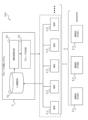
- FIG. 1 is a diagram illustrating a configuration of a wireless network system according to a first embodiment and grouping of terminals; 11A and 11B are diagrams illustrating an example of grouping of terminals and acquisition of communication quality by a representative terminal.
- 11 is a diagram illustrating a first example of broadcast transmission of communication quality from a representative terminal to other terminals.
- FIG. 13 is a diagram illustrating a second example of broadcast transmission of communication quality from a representative terminal to other terminals.
- FIG. FIG. 2 is a diagram illustrating an example of a hardware configuration of the wireless network system according to the first embodiment.
- 4 is a flowchart showing the flow of a first example of a terminal grouping process by the wireless network system according to the first embodiment.
- FIG. 13 is a flowchart showing the flow of a second example of a terminal grouping process by the wireless network system according to the first embodiment.
- FIG. 4 is a flowchart showing the flow of representative terminal switching processing by the wireless network system according to the first embodiment.
- FIG. 4 is a flowchart showing the flow of a communication quality sharing process performed by the wireless network system according to the first embodiment.
- FIG. 11 is a diagram illustrating a configuration of a wireless network system according to a second embodiment.
- First embodiment 1-1 Overview of wireless network system Fig. 1 shows the configuration of a wireless network system 101 according to a first embodiment of the present disclosure. A method for reducing communication overhead according to the present disclosure is applied to the wireless network system 101.
- the wireless network system 101 includes a plurality of terminals 2, a plurality of base stations 3 that perform wireless communication between the terminals 2, and at least one group classification system 4.
- Terminal 2 is a wireless terminal capable of using multiple wireless paths and multiple wireless methods in wireless network system 101.
- One or more base stations 3 are provided for each wireless method.
- Terminal 2 can selectively use wireless methods such as 4G, LTE, and 5G between base stations 3.
- each terminal 2 needs to be distinguished, they are described with independent reference numbers, for example, terminal 2-1, terminal 2-2, ....
- the group classification system 4 is a system that groups the terminals 2 accommodated in the wireless network system 101. As functions for grouping, the group classification system 4 includes an L1 information database 41, a similarity calculation unit 42, and a group determination unit 43.
- the L1 information database 41 is a database in which layer 1 information of all terminals 2 accommodated in the wireless network system 101 is registered. Each terminal 2 acquires layer 1 information for each wireless path and each wireless method used.
- the group classification system 4 collects layer 1 information from each terminal 2 and registers it in the L1 information database 41. There are no limitations on the information items of layer 1 information as long as the information allows the communication environment of a terminal 2 to be compared with other terminals 2.
- the layer 1 information may include the RSSI value, RSRP value, RSRQ value, SINR value, etc. for each base station.
- the group determination unit 43 determines the group to which each terminal 2 accommodated in the wireless network system 101 belongs, based on the similarity of the layer 1 information for all combinations calculated by the similarity calculation unit 42. Specifically, terminals 2 with high similarity are linked together, and groups consisting of multiple terminals 2 are created. Then, ultimately, all terminals 2 belong to one of the groups.
- the group classification system 4 notifies each terminal 2 of the group to which each terminal 2 belongs, determined by the group determination unit 43. Alternatively, the group information may be notified to a representative terminal of each group, which will be described later, and the group information may be notified to the terminals 2 in the group via the representative terminal.
- the L1 information database 41, the similarity calculation unit 42, and the group determination unit 43 are functions of the group classification system 4 divided into three for convenience, and therefore these may be integrated into one or two, or may be further subdivided.
- the group classification system 4 is depicted in FIG. 1 as a system independent of the terminal 2 and the base station 3, the group classification system 4 may be provided in either the terminal 2 or the base station 3. Also, it is possible for some of the functions of the group classification system 4 to be provided in the terminal 2 or the base station 3, and it is also possible for some or all of the functions of the group classification system 4 to be distributed between the terminal 2 and the base station 3.
- the wireless network system 101 is particularly effective in an LOS environment. Therefore, the wireless network system 101 is suitable for application to a wireless network system that accommodates drone-mounted wireless terminals that can easily achieve an LOS environment with the base station 3 by using the sky. Furthermore, if an LOS environment or an environment close to it can be achieved even on the ground, it is also suitable for application to a wireless network system that accommodates portable wireless terminals such as smartphones and stationary wireless terminals. However, the wireless network system 101 can also be used in an environment where an LOS environment and an NLOS environment coexist. Therefore, the wireless network system 101 may include a relay station.
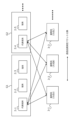
- Figure 2 shows an example of grouping of terminals 2 by the group classification system 4.
- terminals 2-1, 2-2, and 2-3 make up one group (group of terminals) G1.
- Terminals 2-4 and 2-5 make up another group G2.
- the aforementioned similarity is high between terminals 2 belonging to group G1, and high between terminals 2 belonging to group G2.
- the similarity is low between terminals 2 belonging to group G1 and terminals 2 belonging to group G2.
- a representative terminal is then determined to represent each group.
- the representative terminal is determined by the group classification system 4 when the groups are determined.
- the representative terminal may be determined among the terminals in the group according to a predetermined rule.
- the representative terminal of group G1 is terminal 2-1
- the representative terminal of group G2 is terminal 2-4.
- terminal 2-1 may be referred to as representative terminal 2-1
- terminal 2-4 may be referred to as representative terminal 2-4.
- the representative terminal exchanges packets with each base station with which it communicates, and measures the communication quality with each base station. For example, various communication qualities such as channel information, required bandwidth, packet loss rate, available rate, delay, jitter, and error rate are measured by the representative terminal. In the wireless network system 101, only the representative terminal measures communication quality. In other words, the representative terminal has the role of measuring communication quality on behalf of the group. In the example shown in FIG. 2, the representative terminal 2-1 exchanges packets with each of the base stations 3-1, 3-2, and 3-3 on behalf of group G1 to measure communication quality, and the representative terminal 2-4 exchanges packets with each of the base stations 3-1, 3-2, and 3-3 on behalf of group G2 to measure communication quality.
- the representative terminal has the role of notifying other terminals in the group of information related to the measured communication quality. For example, representative terminal 2-1 notifies terminals 2-2 and 2-3 in group G1 of information related to communication quality. Furthermore, representative terminal 2-4 notifies terminal 2-5 in group G2 of information related to communication quality. Since each group is made up of terminals with similar communication environments, information related to communication quality measured by the representative terminal can be shared with other terminals in the group.
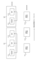
- FIG. 3 is a diagram explaining a first example of broadcast transmission of communication quality from the representative terminal to other terminals.
- broadcast transmission is performed by terminal-to-terminal communication from representative terminal 2-1 to terminals 2-2 and 2-3, and from representative terminal 2-4 to terminal 2-5.
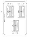
- FIG. 4 is a diagram explaining a second example of broadcast transmission of communication quality from a representative terminal to other terminals.
- broadcast transmission is performed from representative terminal 2-1 to terminals 2-2 and 2-3 via base station 3-1.
- broadcast transmission is performed from representative terminal 2-4 to terminal 2-5 via base station 3-3.
- broadcast transmission is performed via the nearest base station from each group, but it may be via any base station. Of course, the same base station may be used between groups.
- the wireless network system 101 includes the terminal 2, the base station 3, and the group classification system 4.
- the terminal 2 includes a processor 201 and a memory 202.
- the memory 202 stores a plurality of instructions 203 that can be executed by the processor 201.
- the number of each of the processors 201 and memories 202 constituting the terminal 2 may be multiple.
- the wireless network system 101 includes multiple terminals 2.
- the base station 3 includes a processor 301 and a memory 302.
- the memory 302 stores a plurality of instructions 303 that can be executed by the processor 301.
- the number of each of the processors 301 and memories 302 constituting the base station 3 may be multiple.
- the wireless network system 101 includes multiple base stations 3.
- the group classification system 4 includes a processor 401 and a memory 402.
- the memory 402 stores a plurality of instructions 403 executable by the processor 401.
- the memory 402 includes a RAM, a ROM, and storage.
- the aforementioned L1 information database 41 may be provided in the memory 402.
- the number of each of the processors 401 and memories 402 constituting the group classification system 4 may be multiple.
- a part or all of the hardware of the group classification system 4 may be integrated with the terminal 2.
- a part or all of the hardware of the group classification system 4 may be integrated with the base station device 3.
- the wireless network system 101 includes a plurality of executable instructions.
- the plurality of instructions are executed by at least one processor included in the wireless network system 101, whereby the processing described below is executed in the wireless network system 101, and the method of reducing communication overhead of the present disclosure is implemented.
- the program consisting of the plurality of instructions may be stored in a computer-readable non-transitory storage medium, or may be provided via a network.
- the processing executed by the wireless network system 101 includes terminal grouping processing, representative terminal switching processing, and communication quality sharing processing. These processing will be specifically described below with reference to flow charts.
- FIG. 6 is a flow diagram showing the flow of a first example of terminal grouping processing by the wireless network system 101.
- the terminal grouping processing includes processing from step S111 to step S114. There are corresponding instructions for the processing of each step.
- the terminal grouping processing is performed in the wireless network system 101 by executing each instruction by at least one processor.
- step S111 Layer 1 information for each wireless path and each wireless method used by all terminals contained in the wireless network system 101 is measured.
- step S112 the layer 1 information of all terminals measured in step S111 is aggregated.
- step S114 multiple groups are created consisting of multiple terminals with similar communication environments based on the similarity of the layer 1 information between the terminals calculated in step S113.
- Each of the terminals accommodated in the wireless network system 101 is classified into one of the groups.
- FIG. 7 is a flow diagram showing the flow of a second example of the terminal grouping process by the wireless network system 101.
- the terminal grouping process includes the processes from step S121 to step S125. There are corresponding instructions for the processes of each step.
- the terminal grouping process is performed in the wireless network system 101 by executing each instruction by at least one processor.
- step S121 layer 1 information of each wireless path and each wireless method used by all terminals accommodated in the wireless network system 101 is measured. Furthermore, the traffic quality of layers 2 and above is also measured for all terminals.
- the traffic quality measured includes, for example, bit error rate, frame error rate, and retransmission request rate.
- step S122 the layer 1 information of all terminals measured in step S121 is aggregated.
- the product quality of layers 2 and above of all terminals measured in step S121 is aggregated.
- step S123 based on the layer 1 information of all terminals aggregated in step S122, the similarity of the layer 1 information between terminals is calculated for all combinations of terminals.
- step S124 the similarity of the quality of goods at layer 2 or higher between terminals is calculated for all combinations of terminals based on the quality of goods at layer 2 or higher of all terminals aggregated in step S122.
- the calculation of the similarity of the quality of goods at layer 2 or higher is the same as the calculation method of the similarity of layer 1 information. Note that step S124 may be executed prior to step S123 or may be executed simultaneously with step S123.
- step S125 multiple groups are created consisting of multiple terminals with similar communication environments based on the similarity of layer 1 information between the terminals calculated in step S123 and the similarity of the quality of goods at layers 2 and above between the terminals calculated in step S124. That is, in the second example, the similarity of the communication environments is determined from two perspectives: the similarity of layer 1 information and the similarity of the quality of goods at layers 2 and above. Each of the terminals accommodated in the wireless network system 101 is classified into one of the groups.
- a correlation coefficient may be calculated that indicates the correlation between the similarity of layer 1 information between terminals and the similarity of the quality of goods at layers 2 and above between terminals.
- the wireless network system 101 may execute the terminal grouping process of the first or second example described above only once in the initial stage, or may re-execute it periodically or irregularly.
- the terminal grouping process When the terminal grouping process is re-executed, the terminals constituting the group may be replaced each time it is re-executed, or the group may be dissolved or a new group may be created.
- Conditions for re-executing the terminal grouping process may include, for example, the occurrence of an event that clearly causes a loss of similarity in the communication environment, the passage of a certain amount of time, or the detection of terminals with different communication qualities at layer 2 or higher within the group.
- FIG. 8 is a flow diagram showing the flow of representative terminal replacement processing by the wireless network system 101.
- the representative terminal replacement processing includes the processes from step S201 to step S204. There are corresponding instructions for the processing of each step.
- the representative terminal replacement processing is performed in the wireless network system 101 by executing each instruction by at least one processor, as an example, the processor of the current representative terminal.
- step S201 it is determined whether it is time to change the representative terminal.
- One example of when to change is when a predetermined time has passed since the previous change. If it is not yet time to change, the processes from step S202 to step S204 are skipped.
- step S202 When it is time to change the representative terminal, the process of step S202 is executed.
- step S202 the remaining battery power of each terminal in the group is measured.
- the current representative terminal is also included in the measurement of the remaining battery power.
- step S203 terminals in the group whose remaining battery power is below a threshold are excluded from the selection of the representative terminal. This process is performed to protect terminals that are in particular in need of reducing power consumption.
- a representative terminal is determined from among the terminals in the group excluding the terminal excluded in step S203.
- the representative terminal is determined according to a predetermined rule.
- the representative terminal may be determined according to a predetermined order, or may be determined by random selection.
- step S301 the representative terminal measures the communication quality of each wireless path and each wireless method.
- the representative terminal measures the communication quality periodically or irregularly.
- step S302 the representative terminal broadcasts information about communication quality to the other terminals in the group.
- the communication quality of the wireless network measured by the representative terminal is shared between the representative terminal and the other terminals.
- communication quality is not measured individually by each terminal, but only by a representative terminal that represents the group. Since a group is made up of terminals with similar communication environments, the communication quality measured by the representative terminal can be shared within the group. According to the wireless network system 101, the communication quality measured by the representative terminal is shared within the group by broadcast transmission from the representative terminal. This reduces the communication overhead for measuring communication quality in the entire wireless network. In addition, it is possible to obtain an effect that is particularly advantageous for battery-operated terminals, in that the power consumed by the terminals as a whole for measuring communication quality can be reduced.
- the location information database 44 is a database in which the location information of all terminals 2 accommodated in the wireless network system 102 is registered.
- the location information registered in the database may be absolute location information in a global coordinate system, such as location information obtained by a GPS equipped in the terminal 2 or location information obtained by calculation based on the radio wave flight time between each base station 3 and the terminal 2, or it may be relative location information between the terminals 2 measured by terminal-to-terminal communication.
- a representative terminal is determined for each group.
- the representative terminal measures communication quality, and the measured communication quality is notified from the representative terminal to other terminals 2 in the group by broadcast transmission. Therefore, according to the wireless network system 102, it is possible to reduce communication overhead for measuring communication quality in the entire wireless network. It is also possible to suppress the power consumed by terminals 2 as a whole for measuring communication quality.
- the wireless network system 102 according to the first embodiment and the wireless network system 102 according to the second embodiment can be combined. That is, the similarity of the communication environment between the terminals 2 may be determined using both the layer 1 information and the location information of each terminal 2.
Landscapes
- Engineering & Computer Science (AREA)
- Computer Networks & Wireless Communication (AREA)
- Signal Processing (AREA)
- Multimedia (AREA)
- Mobile Radio Communication Systems (AREA)
Abstract
本開示の方法は、複数の無線経路及び複数の無線方式を利用可能な端末を収容する無線ネットワークにおける通信品質の測定のための通信オーバヘッドの削減方法である。本開示の方法によれば、まず、通信環境が類似する複数の端末から構成される端末群が作られる。次に、端末群を代表する代表端末によって各無線経路及び各無線方式の通信品質が測定される。そして、代表端末から端末群を構成する他の端末へ、代表端末により測定された通信品質がブロードキャスト送信される。
Description
本開示は、複数の無線経路及び複数の無線方式を利用可能な端末を収容する無線ネットワークにおける通信品質の測定のための通信オーバヘッドの削減に用いて好適な技術に関する。
ある種の端末は複数の無線経路及び複数の無線方式を通信環境や要求に応じて選択ないし連携して利用することができる。そのためには、端末には、各無線方式の接続可能性やネットワーク情報の他、通信品質(チャネル情報、利用可能レート、遅延、エラー率など)に関する情報を継続的に収集することが求められる。しかし、多数の端末が収容される無線ネットワークでは、各端末において通信品質の測定のための通信が行われた場合、ネットワーク全体における通信品質の測定のための通信オーバヘッドが問題となる。
なお、本開示に関連する技術分野の技術水準を示す文献としては、特許文献1及び非特許文献1を例示することができる。ただし、いずれの文献に開示された技術も上述の問題を解決するものではない。
峰松容浩、岡田啓、小林健太郎、片山正昭、"無線メッシュネットワークにおける自己組織化マップを用いたリンク品質とその相関可視化手法"、電子情報通信学会論文誌B Vol. J100-B No. 2 pp. 100-110 一般社団法人電子情報通信学会2017
本開示は、上述のような課題に鑑みてなされたものである。本開示は、複数の無線経路及び複数の無線方式を利用可能な端末を収容する無線ネットワークにおいて、通信品質の測定のための通信オーバヘッドを削減することを目的とする。
本開示は上記目的を達成するための方法を提供する。本開示の方法は複数の無線経路及び複数の無線方式を利用可能な端末を収容する無線ネットワークにおける通信品質の測定のための通信オーバヘッドの削減方法であって以下の第一乃至第三のステップを含む。第一のステップは、通信環境が類似する複数の端末から構成される端末群を作るステップである。第二のステップは、端末群を代表する代表端末によって各無線経路及び各無線方式の通信品質を測定するステップである。そして、第三のステップは、代表端末から端末群を構成する他の端末へ、代表端末によって測定された通信品質をブロードキャスト送信するステップである。
本開示は上記目的を達成するためのシステムも提供する。本開示のシステムは複数の無線経路及び複数の無線方式を利用可能な端末を収容する無線ネットワークシステムである。本開示のシステムは少なくとも一つのプロセッサと、少なくとも一つのプロセッサと結合される或いは少なくとも一つのプロセッサに内蔵される少なくとも一つのメモリとを備える。少なくとも一つのメモリには、少なくとも一つのプロセッサで実行可能な複数のインストラクションが記憶されている。複数のインストラクションは少なくとも一つのプロセッサに以下の第一乃至第三の処理を実行させるように構成されている。第一の処理は、通信環境が類似する複数の端末から構成される端末群を作る処理である。第二の処理は、端末群を代表する代表端末によって各無線経路及び各無線方式の通信品質を測定する処理である。そして、第三の処理は、代表端末から端末群を構成する他の端末へ、代表端末によって測定された通信品質をブロードキャスト送信する処理である。
また、本開示は上記目的を達成するための端末を提供する。本開示の端末は複数の無線経路及び複数の無線方式を利用可能な端末である。本開示の端末は少なくとも一つのプロセッサと、少なくとも一つのプロセッサと結合される或いは少なくとも一つのプロセッサに内蔵される少なくとも一つのメモリとを備える。少なくとも一つのメモリには、少なくとも一つのプロセッサで実行可能な複数のインストラクションが記憶されている。複数のインストラクションは少なくとも一つのプロセッサに以下の第一乃至第三の処理を実行させるように構成されている。第一の処理は、通信環境が類似する他の一又は複数の端末との間で端末群を作る処理である。第二の処理は、各無線経路及び各無線方式の通信品質を測定する処理である。そして、第三の処理は、測定した通信品質を他の一又は複数の端末へブロードキャスト送信する処理である。
さらに、本開示は上記目的を達成するためのプログラムも提供する。本開示のプログラムは、複数の無線経路及び複数の無線方式を利用可能な端末のプロセッサで実行可能な複数のインストラクションを含むプログラムである。複数のインストラクションはプロセッサに以下の第一乃至第三の処理を実行させるように構成されている。第一の処理は、通信環境が類似する他の一又は複数の端末との間で端末群を作る処理である。第二の処理は、各無線経路及び各無線方式の通信品質を測定する処理である。第三の処理は、測定した通信品質を他の一又は複数の端末へブロードキャスト送信する処理である。なお、本開示のプログラムはコンピュータ読み取り可能な非一時的な記憶媒体に記憶されてもよいし、ネットワークを介して提供されてもよい。
本開示の技術によれば、通信品質の測定は各端末で個別に行われるのではなく、端末群を代表する代表端末のみによって行われる。端末群は通信環境が類似する端末から構成されているので、代表端末が測定した通信品質は端末群内で共有することができる。そして、本開示の技術によれば、代表端末が測定した通信品質の端末群内での共有方法として、代表端末から代表端末以外の端末へのブロードキャスト送信が用いられる。これにより、無線ネットワーク全体における通信品質の測定のための通信オーバヘッドは削減される。
1.第一実施形態
1-1.無線ネットワークシステムの概要
図1は本開示の第一実施形態に係る無線ネットワークシステム101の構成を示す。無線ネットワークシステム101には本開示の通信オーバヘッドの削減方法が適用されている。無線ネットワークシステム101は、複数の端末2と、それら端末2との間で無線通信を行う複数の基地局3、そして、少なくとも1つのグループ分類システム4を備える。
1-1.無線ネットワークシステムの概要
図1は本開示の第一実施形態に係る無線ネットワークシステム101の構成を示す。無線ネットワークシステム101には本開示の通信オーバヘッドの削減方法が適用されている。無線ネットワークシステム101は、複数の端末2と、それら端末2との間で無線通信を行う複数の基地局3、そして、少なくとも1つのグループ分類システム4を備える。
端末2は無線ネットワークシステム101において複数の無線経路及び複数の無線方式を利用可能な無線端末である。基地局3は無線方式毎に一つ又は複数設けられている。端末2は基地局3との間で、例えば、4G、LTE、5Gなどの無線方式を選択的に利用することができる。なお、本明細書及び図面では、端末2のそれぞれを区別する場合には、例えば、端末2-1、端末2-2、・・・と独立した符号を付して記載する。同様に、基地局3のそれぞれを区別する場合には、例えば、基地局3-1、基地局3-2、・・・と独立した符号を付して記載する。
グループ分類システム4は無線ネットワークシステム101に収容されている端末2をグループ化するシステムである。グループ化のための機能として、グループ分類システム4はL1情報データベース41、類似度算出部42、及びグループ決定部43を備える。
L1情報データベース41は、無線ネットワークシステム101に収容されている全ての端末2のレイヤ1情報が登録されたデータベースである。各端末2は利用する各無線経路及び各無線方式のレイヤ1情報を取得する。グループ分類システム4は各端末2からレイヤ1情報を集めてL1情報データベース41に登録する。レイヤ1情報は端末2の通信環境を他の端末2との間で比較できる内容であればその情報項目に限定はない。例えば、レイヤ1情報には基地局毎のRSSI値、RSRP値、RSRQ値、SINR値などが含まれてもよい。
類似度算出部42は、L1情報データベース41に登録されている全ての端末2の組み合わせについてレイヤ1情報の類似度を算出する。例えば、レイヤ1情報がRSSI値である場合、任意の二つの端末2間で基地局毎にRSSI値の差を計算し、その差の合計値をそれら端末2間におけるレイヤ1情報の類似度として算出してもよい(この場合、類似度の値が小さいほど類似度は高いということになる)。端末2間のレイヤ1情報の類似度は、それら端末2が置かれている通信環境の類似性を示している。
グループ決定部43は、類似度算出部42で算出された全組み合わせにおけるレイヤ1情報の類似度に基づき、無線ネットワークシステム101に収容されている各端末2の所属グループを決定する。具体的には、類似度が高い端末2同士が紐づけられていき、複数の端末2からなるグループが作られていく。そして、最終的に全ての端末2がいずれか一つのグループに属することになる。グループ決定部43で決定された各端末2の所属グループは、グループ分類システム4から各端末2に通知される。或いは、後述する各グループの代表端末に所属グループ情報が通知され、代表端末を介してグループ内の端末2に所属グループ情報が通知されてもよい。
なお、L1情報データベース41、類似度算出部42、及びグループ決定部43は、グループ分類システム4が備える機能を便宜上三つに分けたものであるので、これらは一つ又は二つに統合されてもよいし、より細分化されてもよい。また、図1ではグループ分類システム4は端末2及び基地局3とは独立したシステムとして描かれているが、グループ分類システム4はいずれかの端末2に設けられていてもよいし、基地局3に設けられていてもよい。また、グループ分類システム4の一部の機能を端末2又は基地局3に持たせることも可能であるし、グループ分類システム4の一部又は全部の機能を端末2と基地局3とに分散して持たせることも可能である。
グループ分けに用いられるレイヤ1情報の安定性を考慮した場合、無線ネットワークシステム101はLOS環境において特に有効である。ゆえに、無線ネットワークシステム101は、上空を利用することで基地局3との間でLOS環境を容易に実現可能なドローン搭載型の無線端末を収容する無線ネットワークシステムへの適用が好適である。また、地上であってもLOS環境或いはそれに近い環境を実現できる場合には、スマートフォンなどの携帯型の無線端末や定置型の無線端末を収容する無線ネットワークシステムへの適用も好適である。ただし、無線ネットワークシステム101は、LOS環境とNLOS環境とが混在する環での利用も可能である。ゆえに、無線ネットワークシステム101には中継局が含まれてもよい。
図2はグループ分類システム4による端末2のグループ化の例を示す。図2に示す例では、端末2-1、端末2-2、及び端末2-3が一つのグループ(端末群)G1を構成している。また、端末2-4、及び端末2-5は別のグループG2を構成している。グループG1に所属する端末2同士では前述の類似度が高く、グループG2に所属する端末2同士では類似度が高い。しかし、グループG1に所属する端末2とグループG2に所属する端末2とでは類似度が低い。グループ内とグループ間では類似度に明確な差が存在している。
グループが作られた場合、次に、各グループを代表する代表端末が決められる。代表端末の決定は、グループ決めの際にグループ分類システム4により行われる。或いは、グループが決められた後、グループ内の端末間で所定の規則に従って代表端末を決定してもよい。図2に示す例では、グループG1の代表端末は端末2-1であり、グループG2の代表端末は端末2-4である。以下、端末2-1を代表端末2-1と表記し、端末2-4を代表端末2-4と表記する場合がある。
代表端末は、通信対象となる各基地局との間でパケット交換を行い、各基地局との間での通信品質を測定する。例えば、チャネル情報、必要帯域、パケットロス率、利用可能レート、遅延、ジッタ、エラー率等の各種の通信品質が代表端末によって測定される。無線ネットワークシステム101では、通信品質の測定は代表端末のみが行う。すなわち、代表端末はグループを代表して通信品質を測定する役割を有している。図2に示す例では、代表端末2-1はグループG1を代表して各基地局3-1、3-2、3-3との間で通信品質の測定のためのパケット交換を行い、代表端末2-4はグループG2を代表して各基地局3-1、3-2、3-3との間で通信品質の測定のためのパケット交換を行っている。
代表端末は、測定した通信品質に関する情報をグループ内の他の端末に通知する役割を有している。例えば、代表端末2-1はグループG1内の端末2-2、2-3に通信品質に関する情報を通知する。また、代表端末2-4はグループG2内の端末2-5に通信品質に関する情報を通知する。各グループは通信環境が類似する端末で構成されているので、代表端末が測定した通信品質に関する情報は、グループ内の他の端末との間で共有することができる。
代表端末からグループ内の他の端末への通信品質に関する情報の通知は、ブロードキャスト送信によって行われる。図3は、代表端末から他の端末への通信品質のブロードキャスト送信の第一の例について説明する図である。第一の例では、代表端末2-1から端末2-2、2-3へ、また、代表端末2-4から端末2-5へ、端末間通信によるブロードキャスト送信が行われている。
図4は、代表端末から他の端末への通信品質のブロードキャスト送信の第二の例について説明する図である。第二の例では、代表端末2-1から端末2-2、2-3へ、基地局3-1を経由してブロードキャスト送信が行われている。また、代表端末2-4から端末2-5へ、基地局3-3を経由してブロードキャスト送信が行われている。なお、図4では各グループから最も近い基地局を経由してブロードキャスト送信が行われているが、どの基地局を経由してもよい。勿論、グループ間で同じ基地局が用いられてもよい。
1-2.無線ネットワークシステムのハードウェア構成
ここで、無線ネットワークシステム101のハードウェア構成について図5を用いて説明する。前述のように、無線ネットワークシステム101は端末2、基地局3、及びグループ分類システム4を備える。
ここで、無線ネットワークシステム101のハードウェア構成について図5を用いて説明する。前述のように、無線ネットワークシステム101は端末2、基地局3、及びグループ分類システム4を備える。
端末2はプロセッサ201とメモリ202とを備える。メモリ202には、プロセッサ201で実行可能な複数のインストラクション203が記憶されている。端末2を構成するプロセッサ201及びメモリ202の各個数はそれぞれ複数でもよい。無線ネットワークシステム101には複数の端末2が含まれている。
基地局3はプロセッサ301とメモリ302とを備える。メモリ302には、プロセッサ301で実行可能な複数のインストラクション303が記憶されている。基地局3を構成するプロセッサ301及びメモリ302の各個数はそれぞれ複数でもよい。無線ネットワークシステム101には複数の基地局3が含まれている。
グループ分類システム4はプロセッサ401とメモリ402とを備える。メモリ402には、プロセッサ401で実行可能な複数のインストラクション403が記憶されている。メモリ402はRAM、ROM、及びストレージを含む。前述のL1情報データベース41はメモリ402に設けられていてもよい。グループ分類システム4を構成するプロセッサ401及びメモリ402の各個数はそれぞれ複数でもよい。グループ分類システム4の一部又は全部のハードウェアは端末2と一体化されてもよい。また、グループ分類システム4の一部又は全部のハードウェアは基地局装置3と一体化されてもよい。
上記のように無線ネットワークシステム101は実行可能な複数のインストラクションを含む。それら複数のインストラクションが無線ネットワークシステム101に含まれる少なくとも一つのプロセッサで実行されることによって、後述の処理が無線ネットワークシステム101において実行され、本開示の通信オーバヘッドの削減方法が実施される。なお、それら複数のインストラクションで構成されるプログラムはコンピュータ読み取り可能な非一時的な記憶媒体に記憶されてもよいし、ネットワークを介して提供されてもよい。
無線ネットワークシステム101に含まれるプロセッサは、CPU、RISC、DSP、FPGA、ASIC、PLD、又は別の処理ユニットであってもよいし、それらの二つ以上の組合せであってもよいし、後述の処理フローに従って動作する専用プロセッサであってもよい。また、プロセッサはメモリと通信可能に結合されてもよいし、メモリを内蔵してもよい。
1-3.無線ネットワークシステムにより実行される処理
無線ネットワークシステム101により実行される処理には、端末グループ化処理、代表端末交代処理、及び通信品質共有処理が含まれる。以下、これらの処理についてフロー図を用いて具体的に説明する。
無線ネットワークシステム101により実行される処理には、端末グループ化処理、代表端末交代処理、及び通信品質共有処理が含まれる。以下、これらの処理についてフロー図を用いて具体的に説明する。
図6は、無線ネットワークシステム101による端末グループ化処理の第一の例の流れを示すフロー図である。第一の例では、端末グループ化処理はステップS111からステップS114までの処理を含む。各ステップの処理には対応するインストラクションが存在する。それぞれのインストラクションが少なくとも一つのプロセッサによって実行されることで、無線ネットワークシステム101において端末グループ化処理が実行される。
まず、ステップS111では、無線ネットワークシステム101に収容されている全ての端末で、端末が利用する各無線経路及び各無線方式のレイヤ1情報が測定される。
次に、ステップS112では、ステップS111で測定された全端末のレイヤ1情報の集約が行われる。
次に、ステップS113では、ステップS112で集約された全端末のレイヤ1情報に基づき、全ての端末の組み合わせについて、端末間のレイヤ1情報の類似度が算出される。
そして、ステップS114では、ステップS113で算出された端末間のレイヤ1情報の類似度に基づき、通信環境が類似する複数の端末から構成される複数のグループが作られる。無線ネットワークシステム101に収容されている端末のそれぞれは、いずれか一つのグループへ分類される。
図7は、無線ネットワークシステム101による端末グループ化処理の第二の例の流れを示すフロー図である。第二の例では、端末グループ化処理はステップS121からステップS125までの処理を含む。各ステップの処理には対応するインストラクションが存在する。それぞれのインストラクションが少なくとも一つのプロセッサによって実行されることで、無線ネットワークシステム101において端末グループ化処理が実行される。
まず、ステップS121では、無線ネットワークシステム101に収容されている全ての端末で、端末が利用する各無線経路及び各無線方式のレイヤ1情報が測定される。さらに、全ての端末で、レイヤ2以上の通品品質も測定される。測定される通品品質には、例えば、ビット誤り率、フレーム誤り率、再送要求率などが含まれる。
次に、ステップS122では、ステップS121で測定された全端末のレイヤ1情報の集約が行われる。また、ステップS121で測定された全端末のレイヤ2以上の通品品質の集約が行われる。
次に、ステップS123では、ステップS122で集約された全端末のレイヤ1情報に基づき、全ての端末の組み合わせについて、端末間のレイヤ1情報の類似度が算出される。
また、ステップS124では、ステップS122で集約された全端末のレイヤ2以上の通品品質に基づき、全ての端末の組み合わせについて、端末間のレイヤ2以上の通品品質の類似度が算出される。レイヤ2以上の通品品質の類似度が算出は、レイヤ1情報の類似度の算出方法と同様である。なお、ステップS124はステップS123よりも先に実行されてもよいし、同時に実行されてもよい。
そして、ステップS125では、ステップS123で算出された端末間のレイヤ1情報の類似度と、ステップS124で算出された端末間のレイヤ2以上の通品品質の類似度とに基づき、通信環境が類似する複数の端末から構成される複数のグループが作られる。つまり、第二の例では、レイヤ1情報の類似度と、レイヤ2以上の通品品質の類似度という二つの観点で通信環境の類似性が判断される。無線ネットワークシステム101に収容されている端末のそれぞれは、いずれか一つのグループへ分類される。
なお、上記の処理に加えて、端末間のレイヤ1情報の類似度と、端末間のレイヤ2以上の通品品質の類似度との相関を示す相関係数を算出してもよい。そのような相関係数を算出することで、端末間でレイヤ1情報がどれだけ類似していれば、端末間でレイヤ2以上の通品品質がどれだけ類似しているのかを推定することが可能となる。つまり、次回以降の端末グループ化処理では、レイヤ2以上の通品品質を測定せずとも、レイヤ1情報のみを用いてレイヤ2以上の通品品質の類似性を考慮したグループ分けを行うことが可能となる。
無線ネットワークシステム101は、上記の第一の例或いは第二の例の端末グループ化処理を初期段階に一回のみ実行してもよいし、定期的に或いは不定期に再実行してもよい。端末グループ化処理が再実行される場合、再実行の度にグループを構成する端末の入れ替わりが生じることもあれば、グループの解消或いは新たなグループの生成が行われることもある。なお、端末グループ化処理が再実行される条件としては、例えば、明らかに通信環境の類似性が失われるようなイベントが発生した場合、一定の時間が経過した場合、グループ内にレイヤ2以上の通信品質の異なる端末を検出した場合などを挙げることができる。
次に、無線ネットワークシステム101による代表端末交代処理について説明する。各グループの代表端末は固定でもよいが、定期的に或いは不定期に代表端末を交代させてもよい。代表端末は、グループ内の他の端末に通信品質に関する情報をブロードキャスト送信するという役割を有している。このため、代表端末は他の端末と比べて電力負荷が大きい。ゆえに、代表端末を交代させることには、特定の端末に電力負荷が集中することを防止するという効果がある。
図8は、無線ネットワークシステム101による代表端末交代処理の流れを示すフロー図である。代表端末交代処理はステップS201からステップS204までの処理を含む。各ステップの処理には対応するインストラクションが存在する。それぞれのインストラクションが少なくとも一つのプロセッサ、一例としては、現在の代表端末のプロセッサによって実行されることで、無線ネットワークシステム101において代表端末交代処理が実行される。
まず、ステップS201では、代表端末の交代時期かどうかが判定される。交代時期の一例は、前回の交代から所定時間が経過したタイミングである。未だ交代時期が到来していない場合には、ステップS202からステップS204までの処理はスキップされる。
代表端末の交代時期が到来した場合、ステップS202の処理が実行される。ステップS202では、グループ内の各端末のバッテリ残量が測定される。バッテリ残量の測定対象には現在の代表端末も含まれている。
次に、ステップS203では、グループ内の端末のうちバッテリ残量が閾値以下の端末が代表端末の選択から除外される。この処理は消費電力の削減の必要が特に高い端末を保護するために行われる。
そして、ステップS204では、ステップS203で除外された端末を除くグループ内の端末間で代表端末が決定される。代表端末の決定は所定の規則に従って行われる。例えば、予め決められた順序に従って代表端末を決定してもよいし、ランダム選択によって代表端末を決定してもよい。
最後に、無線ネットワークシステム101による通信品質共有処理について説明する。図9は、無線ネットワークシステム101による通信品質共有処理の流れを示すフロー図である。通信品質共有処理はステップS301及びステップS302の処理を含む。各ステップの処理には対応するインストラクションが存在する。それぞれのインストラクションが少なくとも一つのプロセッサ、具体的には、各グループの代表端末のプロセッサによって実行されることで、無線ネットワークシステム101において通信品質共有処理が実行される。
まず、ステップS301では、代表端末によって各無線経路及び各無線方式の通信品質が測定される。代表端末による通信品質の測定は、定期的に或いは不定期に行われる。
そして、ステップS302では、代表端末からグループの他の端末へ通信品質に関する情報がブロードキャスト送信によって通知される。つまり、代表端末と他の端末との間で、代表端末により測定された無線ネットワークの通信品質が共有される。
以上説明したように、無線ネットワークシステム101によれば、通信品質の測定は各端末で個別に行われるのではなく、グループを代表する代表端末のみによって行われる。グループは通信環境が類似する端末から構成されているので、代表端末が測定した通信品質はフループ内で共有することができる。そして、無線ネットワークシステム101によれば、代表端末が測定した通信品質のグループ内での共有方法として、代表端末からのブロードキャスト送信が用いられる。これにより、無線ネットワーク全体における通信品質の測定のための通信オーバヘッドは削減される。また、端末全体として通信品質の測定のために消費する電力を抑制することができるという、バッテリで駆動される端末にとって特に有利な効果も得られる。
2.第二実施形態
図10は本開示の第二実施形態に係る無線ネットワークシステム102の構成を示す。無線ネットワークシステム102にもまた本開示の通信オーバヘッドの削減方法が適用されている。無線ネットワークシステム102は、第一実施形態に係る無線ネットワークシステム101と同様に、複数の端末2と、それら端末2との間で無線通信を行う複数の基地局3、そして、少なくとも1つのグループ分類システム4を備える。また、図5に示す無線ネットワークシステム101のハードウェア構成は無線ネットワークシステム102にも適用される。
図10は本開示の第二実施形態に係る無線ネットワークシステム102の構成を示す。無線ネットワークシステム102にもまた本開示の通信オーバヘッドの削減方法が適用されている。無線ネットワークシステム102は、第一実施形態に係る無線ネットワークシステム101と同様に、複数の端末2と、それら端末2との間で無線通信を行う複数の基地局3、そして、少なくとも1つのグループ分類システム4を備える。また、図5に示す無線ネットワークシステム101のハードウェア構成は無線ネットワークシステム102にも適用される。
本実施形態に係る無線ネットワークシステム102と第一実施形態に係る無線ネットワークシステム101との相違は、グループ分類システム4の機能にある。無線ネットワークシステム102のグループ分類システム4は位置情報データベース44、及びグループ決定部45を備える。
位置情報データベース44は、無線ネットワークシステム102に収容されている全ての端末2の位置情報が登録されたデータベースである。データベースに登録される位置情報は、端末2が備えるGPSによって得られる位置情報や、各基地局3と端末2間の電波飛行時間に基づく計算で得られる位置情報のようなグローバル座標系での絶対的な位置情報でもよいし、端末間通信によって測定される端末2間の相対的な位置情報でもよい。
グループ決定部45は、無線ネットワークシステム102に収容されている各端末2の位置情報に基づき、各端末2の所属グループを決定する。具体的には、空間的位置が近接している端末2同士が紐づけられていき、複数の端末2からなるグループが作られていく。そして、最終的に全ての端末2がいずれか一つのグループに属することになる。
なお、位置情報データベース44及びグループ決定部45は、グループ分類システム4が備える機能を便宜上二つに分けたものであるので、これらは一つに統合されてもよいし、より細分化されてもよい。また、図10ではグループ分類システム4は端末2及び基地局3とは独立したシステムとして描かれているが、グループ分類システム4はいずれかの端末2に設けられていてもよいし、基地局3に設けられていてもよい。また、グループ分類システム4の一部の機能を端末2又は基地局3に持たせることも可能であるし、グループ分類システム4の一部又は全部の機能を端末2と基地局3とに分散して持たせることも可能である。
無線ネットワークシステム102では、第一実施形態に係る無線ネットワークシステム101と同様に、グループ毎に代表端末が決定される。そして、代表端末によって通信品質が測定され、測定された通信品質は代表端末からグループ内の他の端末2へブロードキャスト送信によって通知される。したがって、無線ネットワークシステム102によれば、無線ネットワーク全体における通信品質の測定のための通信オーバヘッドを削減することができる。また、端末2全体として通信品質の測定のために消費する電力を抑制することもできる。
3.その他
第一実施形態に係る無線ネットワークシステム102と第二実施形態に係る無線ネットワークシステム102とは組みわせることができる。すなわち、各端末2のレイヤ1情報と位置情報の両方を用いて端末2間の通信環境の類似度を判定してもよい。
第一実施形態に係る無線ネットワークシステム102と第二実施形態に係る無線ネットワークシステム102とは組みわせることができる。すなわち、各端末2のレイヤ1情報と位置情報の両方を用いて端末2間の通信環境の類似度を判定してもよい。
2 端末
2-1、2-4 代表端末
3 基地局
4 グループ分類システム
101、102 無線ネットワークシステム
G1、G2 グループ(端末群)
2-1、2-4 代表端末
3 基地局
4 グループ分類システム
101、102 無線ネットワークシステム
G1、G2 グループ(端末群)
Claims (8)
- 複数の無線経路及び複数の無線方式を利用可能な端末を収容する無線ネットワークにおける通信品質の測定のための通信オーバヘッドの削減方法であって、
通信環境が類似する複数の前記端末から構成される端末群を作ることと、
前記端末群を代表する代表端末によって各無線経路及び各無線方式の通信品質を測定することと、
前記代表端末から前記端末群を構成する他の端末へ前記通信品質をブロードキャスト送信することと、を含む
ことを特徴とする通信オーバヘッドの削減方法。 - 請求項1に記載の通信オーバヘッドの削減方法において、
前記複数の前記端末のうちバッテリの残量が閾値以下の端末を前記代表端末の選択から除外すること、をさらに含む
を特徴とする通信オーバヘッドの削減方法。 - 請求項1に記載の通信オーバヘッドの削減方法において、
前記複数の前記端末の間で前記代表端末を交代させること、をさらに含む
ことを特徴とする通信オーバヘッドの削減方法。 - 請求項1乃至3のいずれか1項に記載の通信オーバヘッドの削減方法において、
前記端末群を作ることは、レイヤ1情報が類似する端末同士或いは空間的位置が近接した端末同士をグループ化することを含む
ことを特徴とする通信オーバヘッドの削減方法。 - 請求項1乃至3のいずれか1項に記載の通信オーバヘッドの削減方法において、
前記端末群を作ることは、レイヤ1情報が類似し、且つ、レイヤ2以上の通信品質が類似する端末同士をグループ化することを含む
ことを特徴とする通信オーバヘッドの削減方法。 - 複数の無線経路及び複数の無線方式を利用可能な端末を収容する無線ネットワークシステムであって、
少なくとも一つのプロセッサと、
前記少なくとも一つのプロセッサと結合される或いは前記少なくとも一つのプロセッサに内蔵される少なくとも一つのメモリと、
前記少なくとも一つのメモリに記憶された前記少なくとも一つのプロセッサで実行可能な複数のインストラクションと、を備え、
前記複数のインストラクションは前記少なくとも一つのプロセッサに、
通信環境が類似する複数の端末から構成される端末群を作ることと、
前記端末群を代表する代表端末によって各無線経路及び各無線方式の通信品質を測定することと、
前記代表端末から前記端末群を構成する他の端末へ前記通信品質をブロードキャスト送信することと、を実行させるように構成されている
ことを特徴とする無線ネットワークシステム。 - 複数の無線経路及び複数の無線方式を利用可能な端末であって、
少なくとも一つのプロセッサと、
前記少なくとも一つのプロセッサと結合される或いは前記少なくとも一つのプロセッサに内蔵される少なくとも一つのメモリと、
前記少なくとも一つのメモリに記憶された前記少なくとも一つのプロセッサで実行可能な複数のインストラクションと、を備え、
前記複数のインストラクションは前記少なくとも一つのプロセッサに、
通信環境が類似する他の一又は複数の端末との間で端末群を作ることと、
各無線経路及び各無線方式の通信品質を測定することと、
前記他の一又は複数の端末へ前記通信品質をブロードキャスト送信することと、を実行させるように構成されている
ことを特徴とする端末。 - 複数の無線経路及び複数の無線方式を利用可能な端末のプロセッサで実行可能な複数のインストラクションを含むプログラムであって、
前記複数のインストラクションは前記プロセッサに、
通信環境が類似する他の一又は複数の端末との間で端末群を作ることと、
各無線経路及び各無線方式の通信品質を測定することと、
前記他の一又は複数の端末へ前記通信品質をブロードキャスト送信することと、を実行させるように構成されている
ことを特徴とするプログラム。
Priority Applications (2)
| Application Number | Priority Date | Filing Date | Title |
|---|---|---|---|
| JP2025525558A JPWO2024252596A1 (ja) | 2023-06-07 | 2023-06-07 | |
| PCT/JP2023/021252 WO2024252596A1 (ja) | 2023-06-07 | 2023-06-07 | 通信オーバヘッドの削減方法、無線ネットワークシステム、端末、及びプログラム |
Applications Claiming Priority (1)
| Application Number | Priority Date | Filing Date | Title |
|---|---|---|---|
| PCT/JP2023/021252 WO2024252596A1 (ja) | 2023-06-07 | 2023-06-07 | 通信オーバヘッドの削減方法、無線ネットワークシステム、端末、及びプログラム |
Publications (1)
| Publication Number | Publication Date |
|---|---|
| WO2024252596A1 true WO2024252596A1 (ja) | 2024-12-12 |
Family
ID=93795616
Family Applications (1)
| Application Number | Title | Priority Date | Filing Date |
|---|---|---|---|
| PCT/JP2023/021252 Ceased WO2024252596A1 (ja) | 2023-06-07 | 2023-06-07 | 通信オーバヘッドの削減方法、無線ネットワークシステム、端末、及びプログラム |
Country Status (2)
| Country | Link |
|---|---|
| JP (1) | JPWO2024252596A1 (ja) |
| WO (1) | WO2024252596A1 (ja) |
Citations (4)
| Publication number | Priority date | Publication date | Assignee | Title |
|---|---|---|---|---|
| WO2017037845A1 (ja) * | 2015-08-31 | 2017-03-09 | 日本電気株式会社 | ネットワークノードとネットワークシステムと端末、ネットワーク制御方法並びにプログラム |
| JP2018160861A (ja) * | 2017-03-23 | 2018-10-11 | ソニー株式会社 | リモート通信装置、リレー通信装置、基地局、方法及び記録媒体 |
| WO2022201555A1 (ja) * | 2021-03-26 | 2022-09-29 | 株式会社Nttドコモ | 端末、基地局、及び無線通信システム |
| WO2022208825A1 (ja) * | 2021-03-31 | 2022-10-06 | 株式会社Nttドコモ | 端末及び通信方法 |
-
2023
- 2023-06-07 JP JP2025525558A patent/JPWO2024252596A1/ja active Pending
- 2023-06-07 WO PCT/JP2023/021252 patent/WO2024252596A1/ja not_active Ceased
Patent Citations (4)
| Publication number | Priority date | Publication date | Assignee | Title |
|---|---|---|---|---|
| WO2017037845A1 (ja) * | 2015-08-31 | 2017-03-09 | 日本電気株式会社 | ネットワークノードとネットワークシステムと端末、ネットワーク制御方法並びにプログラム |
| JP2018160861A (ja) * | 2017-03-23 | 2018-10-11 | ソニー株式会社 | リモート通信装置、リレー通信装置、基地局、方法及び記録媒体 |
| WO2022201555A1 (ja) * | 2021-03-26 | 2022-09-29 | 株式会社Nttドコモ | 端末、基地局、及び無線通信システム |
| WO2022208825A1 (ja) * | 2021-03-31 | 2022-10-06 | 株式会社Nttドコモ | 端末及び通信方法 |
Also Published As
| Publication number | Publication date |
|---|---|
| JPWO2024252596A1 (ja) | 2024-12-12 |
Similar Documents
| Publication | Publication Date | Title |
|---|---|---|
| US10743248B2 (en) | Establishing communication with multiple networks to enable continuous communication coverage across the multiple networks | |
| EP2953393B1 (en) | Communications control device, communications control method, program, and terminal device | |
| US20130077562A1 (en) | Transport channel flexibility over satellite backhaul links | |
| US11243290B2 (en) | Future position estimation for improved reliability of connectivity | |
| EP4147502B1 (en) | User equipment, network node and methods in a radio communications network | |
| US10591577B2 (en) | Positioning method and device | |
| JP2017098797A (ja) | 無線通信システム、集中制御局及び可動無線局制御方法 | |
| US9949187B2 (en) | Mobile wireless terminal and control method | |
| EP2941034B1 (en) | Communication system, communication control apparatus, wireless communication apparatus, and communication method | |
| US20210176722A1 (en) | Base station, communication system, communication method, and program | |
| US20150382203A1 (en) | Radio wave observation system, central station device, and radio wave observation method | |
| WO2022153636A1 (ja) | 端末装置、基地局装置、及び基地局管理装置 | |
| KR102538867B1 (ko) | 네트워크 계획 및 제어를 위한 공중-대-지상 네트워크 파라미터들의 수동적 수집 | |
| US20230413082A1 (en) | Method and device for acquiring measurement information for terminal | |
| Ali et al. | Internet of things (IoT) considerations, requirements, and architectures for disaster management system | |
| US11770754B2 (en) | Network management apparatus, network management method, and storage medium for network comprising a plurality of vehicles and plurality of mobile terminals | |
| US20180063810A1 (en) | Positioning parameter exchange method and system, and apparatus | |
| US11503528B2 (en) | Base station, terminal device, control method, and program for handover connections | |
| EP3461165B1 (en) | Management server, communication device, method, and recording medium | |
| CN118510048B (zh) | 网络频率复用的方法、装置、计算机设备、可读存储介质和程序产品 | |
| US20150207860A1 (en) | Information distribution system, information distribution server, information distribution method, and program | |
| Uchida et al. | Proposal of Vehicle-to-Vehicle Based Delay Tolerant Networks with Adaptive Aray Antenna Control Systems | |
| dos Santos et al. | Characterization of a delay and disruption tolerant network in the Amazon basin | |
| US12035265B2 (en) | Base station, communication system, communication method, and program | |
| EP3429272B1 (en) | Communication method, forwarding device, and terminal device |
Legal Events
| Date | Code | Title | Description |
|---|---|---|---|
| 121 | Ep: the epo has been informed by wipo that ep was designated in this application |
Ref document number: 23940697 Country of ref document: EP Kind code of ref document: A1 |
|
| ENP | Entry into the national phase |
Ref document number: 2025525558 Country of ref document: JP Kind code of ref document: A |
|
| NENP | Non-entry into the national phase |
Ref country code: DE |