WO2024251347A1 - Longitudinal tyre force estimation - Google Patents
Longitudinal tyre force estimation Download PDFInfo
- Publication number
- WO2024251347A1 WO2024251347A1 PCT/EP2023/065014 EP2023065014W WO2024251347A1 WO 2024251347 A1 WO2024251347 A1 WO 2024251347A1 EP 2023065014 W EP2023065014 W EP 2023065014W WO 2024251347 A1 WO2024251347 A1 WO 2024251347A1
- Authority
- WO
- WIPO (PCT)
- Prior art keywords
- tyre
- wheel
- sensor
- data indicative
- speed
- Prior art date
- Legal status (The legal status is an assumption and is not a legal conclusion. Google has not performed a legal analysis and makes no representation as to the accuracy of the status listed.)
- Ceased
Links
Classifications
-
- B—PERFORMING OPERATIONS; TRANSPORTING
- B60—VEHICLES IN GENERAL
- B60C—VEHICLE TYRES; TYRE INFLATION; TYRE CHANGING; CONNECTING VALVES TO INFLATABLE ELASTIC BODIES IN GENERAL; DEVICES OR ARRANGEMENTS RELATED TO TYRES
- B60C23/00—Devices for measuring, signalling, controlling, or distributing tyre pressure or temperature, specially adapted for mounting on vehicles; Arrangement of tyre inflating devices on vehicles, e.g. of pumps or of tanks; Tyre cooling arrangements
- B60C23/06—Signalling devices actuated by deformation of the tyre, e.g. tyre mounted deformation sensors or indirect determination of tyre deformation based on wheel speed, wheel-centre to ground distance or inclination of wheel axle
- B60C23/068—Signalling devices actuated by deformation of the tyre, e.g. tyre mounted deformation sensors or indirect determination of tyre deformation based on wheel speed, wheel-centre to ground distance or inclination of wheel axle by monitoring chassis to tyre distance
-
- B—PERFORMING OPERATIONS; TRANSPORTING
- B60—VEHICLES IN GENERAL
- B60T—VEHICLE BRAKE CONTROL SYSTEMS OR PARTS THEREOF; BRAKE CONTROL SYSTEMS OR PARTS THEREOF, IN GENERAL; ARRANGEMENT OF BRAKING ELEMENTS ON VEHICLES IN GENERAL; PORTABLE DEVICES FOR PREVENTING UNWANTED MOVEMENT OF VEHICLES; VEHICLE MODIFICATIONS TO FACILITATE COOLING OF BRAKES
- B60T8/00—Arrangements for adjusting wheel-braking force to meet varying vehicular or ground-surface conditions, e.g. limiting or varying distribution of braking force
- B60T8/17—Using electrical or electronic regulation means to control braking
- B60T8/171—Detecting parameters used in the regulation; Measuring values used in the regulation
-
- B—PERFORMING OPERATIONS; TRANSPORTING
- B60—VEHICLES IN GENERAL
- B60T—VEHICLE BRAKE CONTROL SYSTEMS OR PARTS THEREOF; BRAKE CONTROL SYSTEMS OR PARTS THEREOF, IN GENERAL; ARRANGEMENT OF BRAKING ELEMENTS ON VEHICLES IN GENERAL; PORTABLE DEVICES FOR PREVENTING UNWANTED MOVEMENT OF VEHICLES; VEHICLE MODIFICATIONS TO FACILITATE COOLING OF BRAKES
- B60T8/00—Arrangements for adjusting wheel-braking force to meet varying vehicular or ground-surface conditions, e.g. limiting or varying distribution of braking force
- B60T8/17—Using electrical or electronic regulation means to control braking
- B60T8/172—Determining control parameters used in the regulation, e.g. by calculations involving measured or detected parameters
- B60T8/1725—Using tyre sensors, e.g. Sidewall Torsion sensors [SWT]
-
- B—PERFORMING OPERATIONS; TRANSPORTING
- B60—VEHICLES IN GENERAL
- B60W—CONJOINT CONTROL OF VEHICLE SUB-UNITS OF DIFFERENT TYPE OR DIFFERENT FUNCTION; CONTROL SYSTEMS SPECIALLY ADAPTED FOR HYBRID VEHICLES; ROAD VEHICLE DRIVE CONTROL SYSTEMS FOR PURPOSES NOT RELATED TO THE CONTROL OF A PARTICULAR SUB-UNIT
- B60W40/00—Estimation or calculation of non-directly measurable driving parameters for road vehicle drive control systems not related to the control of a particular sub unit, e.g. by using mathematical models
- B60W40/12—Estimation or calculation of non-directly measurable driving parameters for road vehicle drive control systems not related to the control of a particular sub unit, e.g. by using mathematical models related to parameters of the vehicle itself, e.g. tyre models
-
- G—PHYSICS
- G01—MEASURING; TESTING
- G01P—MEASURING LINEAR OR ANGULAR SPEED, ACCELERATION, DECELERATION, OR SHOCK; INDICATING PRESENCE, ABSENCE, OR DIRECTION, OF MOVEMENT
- G01P3/00—Measuring linear or angular speed; Measuring differences of linear or angular speeds
- G01P3/36—Devices characterised by the use of optical means, e.g. using infrared, visible, or ultraviolet light
- G01P3/38—Devices characterised by the use of optical means, e.g. using infrared, visible, or ultraviolet light using photographic means
Definitions
- This disclosure relates generally to control of heavy-duty vehicles such as trucks, busses, and construction equipment.
- the disclosure relates to systems and methods for estimating a longitudinal tyre force generated by one or more wheels on a heavy-duty vehicle, and also to systems and methods for detecting tyre explosion.
- the disclosure may be described with respect to a particular vehicle, the disclosure is not restricted to any particular vehicle or vehicle type.
- Tyre force is the force generated between the road surface and the wheels of a vehicle. This tyre force is what moves the vehicle over the road surface.
- a positive tyre force resulting from torque applied by a propulsion device, such as a combustion engine or an electric machine, will accelerate the vehicle as long as it overcomes losses from, e.g., air resistance and rolling resistance.
- Braking by an actuator such as a friction brake or an electric machine generates a negative tyre forces that will decelerate the vehicle.
- the present disclosure relates to sensors, methods, and systems for estimating and/or controlling motion by a heavy-duty vehicle, such as determining longitudinal tyre force and detecting tyre explosion.
- the disclosure relates to a tyre belt speed sensor for a heavy-duty vehicle.
- the sensor comprises a sensor front end configured to sense motion of an outer surface of a tyre, where the outer surface of the tyre is arranged to engage a road surface supporting the heavy-duty vehicle in use.
- the sensor also comprises a sensor back end configured to determine data indicative of an angular speed of a tyre belt of the tyre based on the motion sensed by the sensor front end, and an output port arranged to output the data indicative of the angular speed of the tyre belt.
- a tyre explosion can be detected with low latency and high reliability by monitoring the tyre belt speed and looking for a disturbance in the tyre belt speed data.
- the tyre belt speed can also be combined with axle speed data in order to determine tyre longitudinal force, and also to get an idea about current road friction conditions. Both the tyre longitudinal force data and the data related to current road friction conditions are helpful when controlling motion by a heavy-duty vehicle.
- the sensor front end may, e.g., be realized by a vision-based sensor, a radar transceiver, a roller wheel arrangement, a vibration pick-up member, and/or a Hall effect sensor.
- the sensor front end may be realized in many different ways.
- the sensor front end may comprise one or more sensor devices based on one or more sensor techniques for increased reliability.
- the cost of the sensor front end varies with the selected sensor technique, which means that the sensor can be produced cost- efficiently if a low-cost technique is selected, or as a more high performing sensor if a more expensive sensor technique is selected.
- the sensor back end may, as noted above, be configured to detect a tyre explosion of the tyre based on a detected disturbance in the sensed motion of the outer surface of the tyre.
- This detection technique offers reliable tyre explosion detection with low latency, which is an advantage. It is advantageous to perform tyre explosion detection directly using tyre belt speed data, which is immediately affected by the explosion, instead of more indirect data such as vehicle motion data or wheel speed data, since it takes some time for the tyre explosion to have an effect there.
- the present disclosure also relates to a computer system for controlling the motion of a heavy-duty vehicle.
- the system comprises at least one tyre belt speed sensor as discussed above, at least one axle speed sensor, and processing circuitry.
- the axle speed sensor is arranged to determine an angular speed of a drive axle associated with a wheel of the heavy-duty vehicle that supports the tyre, and to output data indicative of the angular speed of the drive axle on an axle speed sensor output port.
- the processing circuitry is arranged to receive the data indicative of the angular speed of the drive axle and the data indicative of the angular speed of the tyre belt.
- the processing circuitry is also arranged to determine a longitudinal tyre force associated with the wheel based on the data indicative of the angular speed of the drive axle and based on the data indicative of the angular speed of the tyre belt. This way tyre longitudinal force can be determined in a reliable manner and at relatively low cost, which is an advantage.
- the tyre longitudinal force information is very useful when controlling motion by the heavy- duty vehicle.
- the processing circuitry is also arranged to obtain data indicative of a wheel slip associated with the tyre, and also an inverse tyre model representative of a relationship between wheel slip and longitudinal tyre force at different road friction and tyre normal force conditions.
- the processing circuitry can then be arranged to determine a longitudinal tyre force generating capability based on the wheel slip, the longitudinal tyre force, and the inverse tyre model.
- the force generating capability can, for instance, be used in allocating motion requests between motion actuators of the vehicle, where each motion actuator has a respective actuator capability of generating force.
- the present disclosure furthermore relates to a computer system for controlling the motion of a heavy- duty vehicle.
- the system comprises a tyre belt speed sensor, a vehicle speed sensor, and processing circuitry.
- the vehicle speed sensor is arranged to determine data indicative of a longitudinal speed of the vehicle relative to a road surface supporting the vehicle.
- the processing circuitry is arranged to determine a wheel slip associated with the tyre based on the data indicative of the vehicle speed and on the data indicative of the angular speed of the tyre belt.
- This wheel slip is in many ways more accurate than the wheel slip determined based on the speed of rotation of the wheel rim or wheel axle, since it also accounts for pre-tension in the tyre belt.
- dynamic effects involving the resilience of the tyre thread are captured by the wheel slip metric, which is an advantage.
- a computer system for determining a longitudinal tyre force associated with at least one wheel comprised in a wheel and drive axle system on a heavy-duty vehicle.
- the computer system comprises processing circuitry configured to obtain data indicative of an angular speed of a drive axle of the wheel, obtain data indicative of an angular speed of a tyre belt of the wheel, determine a pretension torque of a mechanical system comprising the drive axle and the at least one wheel, in response to an applied torque at the drive axle, and determine the longitudinal tyre force based on the pretension torque and on a pre-determined set of mechanical properties of the at least one wheel and drive axle system.
- This way longitudinal tyre force can be determined in a reliable manner, which is an advantage.
- Figure 1 illustrates an example heavy-duty vehicle
- Figure 2 schematically shows an example wheel with a tyre belt speed sensor
- Figures 3A-B schematically illustrate a wheel and a wheel driveline
- Figure 4 shows aspects of an example vehicle control system
- Figures 5 A-D show some example general tyre belt speed sensor principles
- Figure 6 is a graph illustrating a relationship between wheel slip and tyre force
- Figure 7 illustrates an example heavy-duty vehicle with tyre belt speed sensors
- Figure 8 is a schematic diagram of an exemplary computer system
- FIGS 9A-B are flow charts that illustrate methods
- Figure 10 shows an example computer program product.
- Figure 1 illustrates an example heavy-duty vehicle 100, here in the form of a truck comprising a tractor 110 and a trailer 120.
- the tractor 110 of the vehicle 100 comprises two front wheels 101 of a steered front axle and a set of rear wheels 102 on rear tractor axles.
- the trailer 120 also comprises wheels 103 that support it on the road surface 104, in addition to the trailer support at the tractor fifth wheel.
- a heavy-duty vehicle may be defined in some cases as a freight vehicle of more than 3.5 tons or as a passenger transport vehicles of more than 8 seats.
- a heavy-duty vehicle may also be defined as a vehicle with a frontal area that is larger than 45 square feet, which is about 4.18 square meters.
- the vehicle 100 comprises a computer-implemented control system arranged to estimate vehicle motion relative to the road surface 104 and/or in a global reference system.
- the control system implements one or more control functions that control vehicle motion based at least in part on the estimated vehicle motion.
- This control system may comprise one or more control units 130 distributed over the vehicle or centralized at one place.
- Each vehicle control unit 130 may comprise one or more processor devices.
- a processor device may be distributed over several spatially separated units or centralized in one place.
- the control system, or parts thereof, may be arranged to communicate via wireless link 140 to a wireless access point 150, such as a radio base station of a cellular access network or the like.
- the vehicle control system may communicate with one or more remote servers 160 implementing data repositories, remote processing resources, and the like, in order to exchange data and perform various computation tasks.
- the vehicle control system 130 may be referred to as, or form part of, a system for vehicle motion management (VMM).
- VMM vehicle motion management
- data indicative of is to be construed broadly to mean, e.g., the actual value, an approximation of the value, or an abstraction of the value.
- the data can for instance be represented using more or less bits in a digital message or transmitted in analog form.
- a given value may also be represented using an abstraction or code, such as a discrete value from 1-10.
- FIG. 2 schematically illustrates a driven wheel 200. It is appreciated that both the front wheels 101 and the rear wheels 102 of the tractor can be driven, as well as the wheels on the trailer 120, although self-propelled trailer units are less common.
- the wheel 200 comprises a tyre 215.
- the tyre is a ringshaped resilient component that surrounds a wheel's rim 220 to transfer a vehicle's load from the axle through the wheel to the ground and to provide traction on the surface over which the wheel travels.
- Most automotive tyres are pneumatically inflated structures, which also provide a flexible cushion that absorbs shock as the tyre rolls over rough features on the road surface 104.
- the tyre is flexible, which means that it is subject to torsion about the wheel axle as torque is transmitted to it from the road surface or from the drive axle.
- the outer peripheral part of the tyre facing the road surface 104 in use will be referred to generally herein as the tyre belt 210, although it is appreciated that the tyre belt is really the supporting structure commonly arranged just underneath the tyre thread.
- the area of engagement between the road surface 104 and the tyre outer surface is generally referred to as the tyre contact patch, and this is where the tyre force is generated.
- Longitudinal tyre force F x is the force generated along the intersection of the wheel plane and the road surface 104.
- Lateral tyre force F y is perpendicular to the longitudinal tyre force and directed along the road surface.
- the longitudinal and lateral directions are defined in the local coordinate system of a given wheel, which means that the longitudinal direction changes relative to a global reference system if the wheel is steered.
- a tyre normal force F z is normal to the road surface, i.e., substantially vertical in most cases. The present disclosure focuses on determination of tyre longitudinal force F x , although some aspects of the disclosure also relates to the tyre normal force F z .
- a driveline is arranged to transfer an actuator torque T m from a power source 230 such as an electric machine and/or a combustion engine via a gear arrangement 240 associated with a gear ratio i to the wheel rim 220.
- a power source 230 such as an electric machine and/or a combustion engine
- a gear arrangement 240 associated with a gear ratio i to the wheel rim 220.
- the torque T w applied to the wheel rim 215 is then transferred to the road surface 104 via the tyre 215, whereby a longitudinal tyre force F x is generated.
- the power source 230 and associated components are associated with an inertia J m and the tyre 215 is associated with an inertia J b .
- the different inertias in the system is thus assumed to be concentrated at two locations, one is the motor inertia J m , and the other is the wheel ineria J b which is assumed to be located around a ring in the tyre belt (hence the subscript “b” for belt).
- the angular velocity of the drive shaft at the power source 230 is denoted and the angular velocity of the wheel 200 is denoted a> b .
- propulsion i.e., the application of a positive torque T w applied to the wheel rim 215.
- the discussion and mathematical derivations presented herein can be generalized to also apply to negative applied torques T w applied to the wheel rim 215, as will be the case if a braking device such as a friction brake is actuated, or if an electric machine is used to apply negative actuator torque T m instead of positive actuator torque T m .
- the wheel radius r may be specified as an effective rolling radius of the wheel, or as a nominal radius of the wheel.
- Longitudinal tyre force F x is often estimated from a measured actuator torque T m by converting the measured actuator torque T m based on gear ratio i and nominal tyre radius r into tyre force F x .
- This approach has its limitations, in particular during transient motion events, i.e., when the vehicle accelerates or decelerates. This is because the relaxation of the tyre 215 is not accounted for. The force pretension of the tyre side wall and tyre thread is neglected which can lead to significant force estimation errors in some cases.
- the tyre 215 that connects the wheel axle to the road surface 104 in torque transferring relation has a modelled stiffness k t and damping c t , which in some cases have significant effect on the transient response by the tyre to a torque applied at the wheel rim 220.
- the stiffness k s and damping c s of the drive shaft and other components in the driveline from the power source 230 or service brake to the wheel rim 215 are also often neglected, adding to the force estimation error.
- Other non-rigid components may also add to the force estimation error, such as resilience in the gear arrangement, and in connections between wheel axle and wheel hub.
- the approach to determining longitudinal tyre force F x proposed herein relies on measuring the output axle speed at the power source 230, or at least close to the power source 230, e.g., by an axle speed sensor 250, and also the angular velocity a> b of the tyre belt 210.
- the output axle speed a> m of the power source 230 can be determined by a rotary encoder, or by a rotation speed sensor such as a Hall effect sensor or the like.
- rotary encoder There are two main types of rotary encoder: absolute and incremental.
- the output of an absolute encoder indicates the current shaft or axle position, making it an angle transducer.
- the output of an incremental encoder provides information about the rotary motion of the shaft.
- the tyre belt speed a> b can be determined by a special tyre belt speed sensor 260.
- the tyre belt speed sensor 260 may, e.g., comprise a radar-based sensor, a vision-based sensor, a vibration pick-up sensor or a roller contact sensor, and will be discussed in more detail below in connection to Figures 5A-D.
- the tyre belt speed sensor 260 provides an output signal that is indicative of the tyre belt speed a> b . Both the axle speed sensor 250 and the tyre belt speed sensor 260 provide output signals to the control unit 130.
- a model of torque transfer between power source 230 and tyre belt 210 can be used to determine the longitudinal tyre force that is currently generated at the contact patch between a given wheel and the road surface 104. This way the accuracy of the estimated longitudinal tyre force F x increases, at least in part since some transient effects are now also accounted for.
- the model parameters e.g., stiffnesses etc.
- the parameters can be estimated online, e.g., by probing torque to wheels and measuring the response of the system using an accelerometer.
- the parameters can also be estimated off-line, e.g., by tuning in a workshop or laboratory, or by measuring rotational torsion and belt force at the wheel in response to an applied actuator torque.
- the model can be expanded to cover an arbitrary number of actuators in a straight-forward manner.
- the model can also be expanded to cover an arbitrary number of wheels for a given actuator in a straight-forward manner.
- the shaft angle after the gear arrangement 320 is denoted 9 g and the applied torque on the output from the gear arrangement 320 is denoted T g , respectively.
- the angle of the tyre belt is denoted by 9 b .
- These angles may be defined as an angular displacement of the axle and tyre belt in relation to some reference direction, such as a horizontal axis or vertical axis.
- Angular acceleration is denoted 9 b and 9 m , respectively.
- At least the tyre side wall and the drive shaft are resilient objects, i.e., somewhat elastic, and since they are connected in series, they can be considered as one lumped element 330 with a stiffness k and damping d.
- a wheel with tyre radius r and a tyre belt with inertia J b is connected to the vehicle body with mass m.
- v x The velocity of the vehicle in longitudinal direction is denoted v x , this velocity must be translated into the wheel local coordinate system if it is to be compared to the tyre belt speed m b .
- Losses due to air drag etc. are denoted by F L in Figures 3A-B. Accounting for these losses is not strictly necessary, but an improved accuracy will be obtained if they are accounted for, at least approximatively.
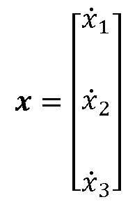
- x r represents the combined pretention of the drive shaft and the tyre side wall
- x 2 is associated with the power source shaft angular speed
- x 3 is associated with the tyre belt angular speed m b .
- a system model can now be set up for the system 300.
- the measurements of the state variables x r and x 2 and the process model can now be used to estimate the pretention x> that is not directly measurable, at least not with this sensor set-up.
- a standard filter can be used to estimate the pretention variable x> over time, such as a Kalman filter, and extended Kalman filter, a particle filter or a Luenberger observer structure, which are all well known in the art and will therefore not be discussed in more detail herein.
- the measured actuator torque T m is used to parameterize the process equation and used as input to the filter structures.
- the output from the filter is an estimate of the state vector x, which among other things comprises the pretention variable x 3 .
- the longitudinal tyre force F x can now be found by using the estimates x r and x 3 along with their respective time derivatives.
- F x - r
- F x denotes an estimate of F x .
- Another model which can be used in a similar function is one where the states are given by where 3 r is wheel rim angle.
- the system model then becomes where J r is the wheel rim inertia and is friction brake torque, and where the stiffness and damping in the system have been divided up as k s , k t and d s , d t .
- the output from the sensor arrangement is
- this model is parameterized by the tyre force F x , the motor torque T m , and a friction brake torque T b .
- a computer system 130, 800 for controlling motion of a heavy-duty vehicle 100.
- the system comprises at least one tyre belt speed sensor 260 with a corresponding axle speed sensor 250 and processing circuitry.
- a tyre belt speed sensor is a sensor that is configured to sense motion of an outer surface of a tyre 215, preferably the part of the tyre 215 that engages the road surface 104 in use.
- the tyre belt speed sensor is useful for many things, among which is to provide data on the tyre belt speed .
- Some example tyre belt speed sensors will be discussed in more detail below in connection to Figures 5A-D.
- the axle speed sensor 250 is arranged to determine an angular speed of a drive axle associated with a wheel 101, 102, 103 of the heavy-duty vehicle 100 that supports the tyre 215. This sensor outputs data indicative of the angular speed of the drive axle on an axle speed sensor output port. It is appreciated that the axle speed sensor output port and/or the output port of the tyre belt speed sensor that is arranged to output data indicative of the angular speed a> b of the tyre belt 210 may be internal to the computer system 130, 800 or external to the computer system, i.e., connected to the computer system 130, 800 by wire or wireless interface.
- the processing circuitry is arranged to determine the longitudinal tyre force F x associated with the wheel 101, 102, 103 based on the data indicative of the angular speed of the drive axle and based on the data indicative of the angular speed a> b of the tyre belt 210, e.g., by using the methods discussed above or an alternative method in line with the general discussions herein.
- a computer system 130, 800 for determining a longitudinal tyre force F x associated with at least one wheel 101, 102, 103, 200 comprised in a wheel and drive axle system 300 on a heavy-duty vehicle 100.
- the computer system 130, 800 comprises processing circuitry configured to obtain data indicative of an angular speed a> m of a drive axle of the wheel 101, 102, 103, 200, obtain data indicative of an angular speed a> b of a tyre belt 210 of the wheel 101, 102, 103, 200, determine a pretension torque x r of a mechanical system comprising the drive axle and the at least one wheel, in response to an applied torque T m at the drive axle, and also determine the longitudinal tyre force F x based on the pretension torque x r and on a pre-determined set of mechanical properties of the at least one wheel and drive axle system 300.
- the set of mechanical properties of the at least one wheel and drive axle system 300 may comprise a lumped stiffness coefficient k and a lumped damping coefficient d of the wheel and drive axle system 300, as illustrated in Figure 3B.
- the stiffness and damping in the mechanical system may also be divided up into more than one component and modelled accordingly.
- Each wheel 101, 102, 103 on the vehicle 100 has a longitudinal velocity component v x and a lateral velocity component v y (in the coordinate system of the wheel or in the coordinate system of the vehicle, depending on implementation).
- the tyre forces are defined in the coordinate system of the wheel, i.e., the longitudinal force is directed in the rolling plane of the wheel, while the lateral tyre force is directed normal to the rolling plane of the wheel.
- the TSM function 410 generates vehicle motion requests which may comprise a desired curvature c req to be followed by the vehicle, and desired vehicle unit accelerations a req . Given the discussion above, it is appreciated that the motion request will have an impact on the expected nominal difference in tyre rotary motion.
- the VMM system 420 operates with a time horizon of about 1 second or so, and continuously transforms the acceleration profdes a req and curvature profdes c req from the TSM function 410 into control commands 431, 432, 433 for controlling vehicle motion functions, actuated by the different MSDs of the vehicle 100 which report back capabilities 434, 435, 436 to the VMM function 420, which in turn may be used as constraints in the vehicle control.
- One example such constraint may be the maximum achievable longitudinal tyre force as discussed in connection to Figure 6.
- the VMM system 420 performs vehicle state or motion estimation 450, i.e., the VMM system 420 continuously determines a vehicle state s as function of time t comprising positions, speeds, accelerations, and articulation angles of the different units in the vehicle combination by monitoring operations using various sensors 440 arranged on the vehicle 100, often but not always in connection to the MSDs.
- An important input to the state estimation 450 may of course be the signals from the vehicle speed sensor and the wheel speed sensors on the heavy-duty vehicle 100, as well as the signals from one or more tyre belt speed sensors 260 on the vehicle.
- the vehicle state at a future time instant can also be predicted by a state prediction function 455.
- This vehicle state prediction function may be realized by a vehicle model having a vehicle state which can be extrapolated into a predicted vehicle state, given a current vehicle state, and optionally also given the current vehicle motion request.
- This example has two vehicle units. More vehicle units are possible, and also a single vehicle unit, e.g., in case the vehicle is a rigid truck or a passenger car.
- the required global force vector V is input to an MSD coordination function 470 which allocates tyre forces and coordinates other MSDs such as steering and suspension.
- the coordination by the MSD coordination function is advantageously performed by taking the longitudinal tyre force generating capabilities of the different wheels into account. This information can be obtained from the tyre force monitor function or be determined based on data received from the tyre force monitor function 480.
- the state estimation function may also benefit from input data from the tyre force monitoring function 480, regarding longitudinal tyre force at the different tyres for instance.
- the MSD coordination function outputs an MSD control allocation for the i:th wheel, which may comprise any of a torque T,. a longitudinal wheel slip a wheel rotational speed ⁇ »i, and/or a wheel steering angle 8i.
- the MSD coordination function may, e.g., be realized using a mathematical optimization problem solver which finds a control allocation that fulfils the global force requirements and at the same time does not allocate a motion request to some MSD that it cannot fulfil.
- Several MSD coordination functions have been described previously in the literature. MSD coordination functions will therefore not be discussed in more detail herein.
- the coordinated MSDs then together provide the desired lateral Fy and longitudinal Fx forces on the vehicle units, as well as the required moments Mz, to obtain the desired motion by the vehicle combination 100.
- the VMM system 420 manages both force generation and MSD coordination, i.e., it determines what forces that are required at the vehicle units in order to fulfil the requests from the TSM function 410, for instance to accelerate the vehicle according to a requested acceleration profile requested by TSM and/or to generate a certain curvature motion by the vehicle also requested by TSM.
- the forces may comprise e.g., yaw moments Mz, longitudinal forces Fx and lateral forces Fy, as well as different types of torques to be applied at different wheels.
- the forces are determined such as to generate the vehicle behavior which is expected by the TSM function in response to the control inputs generated by the TSM function 410.
- Figures 5A-D illustrate some general principles of tyre belt speed sensors 260 for use with heavy-duty vehicles, such as the vehicle 100 illustrated in Figure 1.
- Figure 5 A schematically illustrates a tyre belt speed sensor 260 for a heavy-duty vehicle 100.
- the sensor 260 comprises a sensor front end 510 configured to sense 515 motion of an outer surface of a tyre 215, i.e., the part of the tyre 215 that is arranged to engage the road surface 104 supporting the heavy-duty vehicle 100 in use.
- the tyre belt speed sensor 260 is configured to sense a motion of the tyre thread part of the tyre 215, but relevant data can also be obtained from a sensor configured to sense a motion of the outer side walls of the tyre.
- a roller wheel arrangement can be arranged to engage the side of the tyre, like a dynamo on a bicycle tyre. Magnets can also be embedded into the tyre side wall and detected as they pass a Hall effect sensor or the like.
- a sensor back end 520 is configured to determine data indicative of an angular speed a> b of the tyre belt 210 of the tyre 215 based on the motion sensed by the sensor front end 510, while an output port 530 is arranged to output the data indicative of the angular speed a> b of the tyre belt 210, e.g., to the control unit 130 or to some other processing device.
- Figure 5B illustrates two example tyre belt speed sensor principles.
- the sensor front end 510 comprises a vision-based sensor 540 arranged to capture a sequence of images of the outer surface of the tyre 215 at respective image capture time instants.
- the sensor back end 520 is configured to determine the data indicative of the angular speed a> b based on a comparison of the images in the captured sequence of images and on the respective image capture time instants.
- the sensor back-end may, e.g., implement a correlation function that determines how far the tyre thread pattern has shifted from one image in the sequence to the next, from which shift distance the tyre belt speed can be determined, as long as the time in between images is at least approximately known.
- the sensor back-end may of course implement a filter also to suppress noise, and to average over a number of images in the sequence.
- the vision-based sensor can be a camera of low resolution, and possibly only a binary color image capture element, i.e., a black and white camera sensor.
- the camera sensor may not work efficiently under dark operating conditions and may need a light to complement it in order to operate efficiently during night and in other dark operating conditions.
- Figure 5B also illustrates an example tyre belt speed sensor, where the sensor front end 510 comprises a Hall effect sensor 580 arranged to detect passage of a plurality of magnets 585 attached to or embedded in the outer part of the tyre 215.
- the sensor back end 520 is here configured to determine the data indicative of the angular speed a> b based on the frequency of detected passages by the Hall effect sensor 580 and on data associated with a tangential distance between the plurality of magnets 585.
- the data associated with a tangential distance between the plurality of magnets 585 may be a preconfigured value or determined by a calibration operation involving input from an external travelled distance sensor or vehicle speed sensor.
- the sensor front end 510 comprises a radar transceiver 550 with a bore-sight direction B arranged pointing at the outer surface of the tyre 215 at an angle a relative to a radial direction D of the tyre 215.
- the sensor back end 520 is in this case configured to determine the data indicative of the angular speed a> b based on a Doppler shift of radar signal backscatter received from the tyre 215.
- Figure 5D illustrates two example tyre belt speed principles.
- the sensor front end 510 comprises a roller wheel arrangement 560 arranged in use to engage the tyre in rolling contact 565.
- the sensor back end 520 is configured to determine the data indicative of the angular speed a> b based on a measured rotation speed of the roller wheel arrangement 560.
- the roller wheel arrangement may be configured to engage the radial outer part of the tyre side wall instead of the tyre thread, which gives less disturbance from the tyre thread.
- the sensor front end 510 comprises a vibration pick-up member 570 arranged in use to engage the outer surface of the tyre 215 is also shown in Figure 5D.
- the sensor back end 520 is configured to determine the data indicative of the angular speed a> b based on a vibration of the vibration pick-up member 570 and on data associated with a tyre thread pattern of the tyre 215.
- the sensor back end 520 is optionally also configured to detect a tyre explosion of the tyre 215 based on a detected disturbance in the sensed motion of the outer surface of the tyre 215. Any of the tyre belt speed sensor principles can be used for this additional purpose.
- a tyre explosion normally causes significant deformation of the outer surface of the tyre 215. Hence, if the sensor front end 510 outputs a signal indicative of great disturbance, then a tyre explosion may have occurred.
- Longitudinal wheel slip x l for the /-th wheel on the vehicle 100 may, in accordance with SAE J370 (SAE Vehicle Dynamics Standards Committee January 24, 2008) be defined as
- the wheel slip x is bounded between -1 and 1 and quantifies how much the wheel is slipping with respect to the road surface 104.
- Wheel slip is, in essence, a speed difference measured between the tyre belt tangential speed and the vehicle but normalized with speed.
- the angular velocity of the wheel rim 220 is often used to determine wheel slip since it can be sensed by a wheel speed sensor in an efficient and reliable manner.
- this requires the effective rolling radius r of the wheel to be known, which is not always the case, since it changes with, e.g., temperature of the tyre, tyre wear, tyre inflation pressure, and wheel normal load.
- Using the wheel rim rotation speed also fails to account for transients in wheel slip due to the relaxation of the tyre side wall and tyre thread which are not rigid objects, but subject to deformation.
- the tyre belt speed as sensed by a tyre belt speed sensor, instead of wheel rim speed, more accurate wheel slip data is obtained which is also independent of wheel radius, and therefore not affected by inaccuracies in wheel radius data.
- Figure 6 is a graph showing an example 600 of achievable tyre force as function of longitudinal wheel slip.
- F x is the longitudinal tyre force while F y is the maximum obtainable lateral tyre force for a given wheel slip.
- This type of relationship between wheel slip and generated tyre force is often referred to as an inverse tyre model, and it is generally known. Since the tyre characteristics are not monotonically growing for larger slip values, the inverse tyre model does not exist for all slip values. Therefore, the inverse is normally taken from zero force up to the peak force.
- the examples in Figure 6 are for positive tyre forces, i.e., acceleration. Similar relationships exist between wheel slip and negative tyre force, i.e., braking.
- the relationship is approximately linear in a region 610 below some wheel slip threshold value, and then exhibits non-linearity in the region 620.
- the maximum obtainable longitudinal tyre force F x is bounded by the product of the road friction coefficient /z and the wheel normal force F z . Hence, if either friction or normal force or both decrease, the force generating capability of the wheel also decreases. This is illustrated in Figure 6 by the three curves 630, 640 and 650, where Mi F Z1 > /r 2 F Z 2 > F?,F Z ?, .
- the processing circuitry discussed above is optionally arranged to obtain data indicative of a wheel slip x associated with the tyre 215, and an inverse tyre model 600 representative of a relationship between wheel slip and longitudinal tyre force at different road friction /z and tyre normal force F x conditions, and to determine a longitudinal tyre force F x generating capability based on the wheel slip x , the longitudinal tyre force F x , and the inverse tyre model 600. Since it is now possible to determine the longitudinal tyre force F x including dynamics, it also becomes possible to determine wheel slip including dynamics, which is an advantage.
- the processing circuitry can be arranged to determine a wheel slip x associated with the tyre 215 based on the data indicative of the vehicle speed v x and on the data indicative of the angular speed a> b of the tyre belt 210.
- This wheel slip is then determined independently of any errors in wheel radius information available to the processing circuitry, which is an advantage.
- the wheel slip determined based on tyre belt speed also accounts for transient effects due to elasticity in the tyre, which is an advantage.
- Figure 7 illustrates a heavy-duty vehicle where tyre belt speed sensors 260 have been arranged in connection to several of the wheels on the vehicle 100.
- the control unit 130 is configured to determine a respective tyre force for each of the wheels comprising a tyre belt speed sensor. This data is of course very useful in a heavy-duty VMM system such as the system 400 discussed above.
- the control unit 130 may of course also be configured to determine tyre force generating capability, and also detect tyre explosion by using the plurality of tyre belt speed sensors 260 on the heavy-duty vehicle.
- Figure 8 is a schematic diagram of a computer system 800 for implementing examples disclosed herein.
- the computer system 800 is adapted to execute instructions from a computer-readable medium to perform these and/or any of the functions or processing described herein.
- the computer system 800 may be connected (e.g., networked) to other machines in a LAN, an intranet, an extranet, or the Internet. While only a single device is illustrated, the computer system 800 may include any collection of devices that individually or jointly execute a set (or multiple sets) of instructions to perform any one or more of the methodologies discussed herein.
- any reference in the disclosure and/or claims to a computer system, computing system, computer device, computing device, control system, control unit, electronic control unit (ECU), processor device, etc. includes reference to one or more such devices to individually or jointly execute a set (or multiple sets) of instructions to perform any one or more of the methodologies discussed herein.
- a control system may include a single control unit, or a plurality of control units connected or otherwise communicatively coupled to each other, such that any performed function may be distributed between the control units as desired.
- such devices may communicate with each other or other devices by various system architectures, such as directly or via a Controller Area Network (CAN) bus, etc.
- CAN Controller Area Network
- the computer system 800 may comprise at least one computing device or electronic device capable of including firmware, hardware, and/or executing software instructions to implement the functionality described herein.
- the computer system 800 may include a processor device 802 (may also be referred to as a control unit), a memory 804, and a system bus 806.
- the computer system 800 may include at least one computing device having the processor device 802.
- the system bus 806 provides an interface for system components including, but not limited to, the memory 804 and the processor device 802.
- the processor device 802 may include any number of hardware components for conducting data or signal processing or for executing computer code stored in memory 804.
- the processor device 802 may, for example, include a general-purpose processor, an application specific processor, a Digital Signal Processor (DSP), an Application Specific Integrated Circuit (ASIC), a Field Programmable Gate Array (FPGA), a circuit containing processing components, a group of distributed processing components, a group of distributed computers configured for processing, or other programmable logic device, discrete gate or transistor logic, discrete hardware components, or any combination thereof designed to perform the functions described herein.
- the processor device may further include computer executable code that controls operation of the programmable device.
- the system bus 806 may be any of several types of bus structures that may further interconnect to a memory bus (with or without a memory controller), a peripheral bus, and/or a local bus using any of a variety of bus architectures.
- the memory 804 may be one or more devices for storing data and/or computer code for completing or facilitating methods described herein.
- the memory 804 may include database components, object code components, script components, or other types of information structure for supporting the various activities herein. Any distributed or local memory device may be utilized with the systems and methods of this description.
- the memory 804 may be communicably connected to the processor device 802 (e.g., via a circuit or any other wired, wireless, or network connection) and may include computer code for executing one or more processes described herein.
- the memory 804 may include non-volatile memory 808 (e.g., read-only memory (ROM), erasable programmable read-only memory (EPROM), electrically erasable programmable read-only memory (EEPROM), etc.), and volatile memory 810 (e.g., random-access memory (RAM)), or any other medium which can be used to carry or store desired program code in the form of machine-executable instructions or data structures, and which can be accessed by a computer or other machine with a processor device 802.
- a basic input/output system (BIOS) 812 may be stored in the non-volatile memory 808 and can include the basic routines that help to transfer information between elements within the computer system 800.
- BIOS basic input/output system
- the computer system 800 may further include or be coupled to a non-transitory computer-readable storage medium such as the storage device 814, which may comprise, for example, an internal or external hard disk drive (HDD) (e.g., enhanced integrated drive electronics (EIDE) or serial advanced technology attachment (SATA)), HDD (e.g., EIDE or SATA) for storage, flash memory, or the like.
- HDD enhanced integrated drive electronics
- SATA serial advanced technology attachment
- the storage device 814 and other drives associated with computer-readable media and computer-usable media may provide non-volatile storage of data, data structures, computer-executable instructions, and the like.
- modules can be implemented as software and/or hard coded circuitry to implement the functionality described herein in whole or in part.
- the modules may be stored in the storage device 814 and/or in the volatile memory 810, which may include an operating system 816 and/or one or more program modules 818. All or a portion of the examples disclosed herein may be implemented as a computer program product 820 stored on a transitory or non-transitory computer-usable or computer- readable storage medium (e.g., single medium or multiple media), such as the storage device 814, which includes complex programming instructions (e.g., complex computer-readable program code) to cause the processor device 802 to carry out the steps described herein.
- complex programming instructions e.g., complex computer-readable program code
- the computer-readable program code can comprise software instructions for implementing the functionality of the examples described herein when executed by the processor device 802.
- the processor device 802 may serve as a controller or control system for the computer system 800 that is to implement the functionality described herein.
- the computer system 800 also may include an input device interface 822 (e.g., input device interface and/or output device interface).
- the input device interface 822 may be configured to receive input and selections to be communicated to the computer system 800 when executing instructions, such as from a keyboard, mouse, touch-sensitive surface, etc.
- Such input devices may be connected to the processor device 802 through the input device interface 822 coupled to the system bus 806 but can be connected through other interfaces such as a parallel port, an Institute of Electrical and Electronic Engineers (IEEE) 1394 serial port, a Universal Serial Bus (USB) port, an IR interface, and the like.
- the computer system 800 may include an output device interface 824 configured to forward output, such as to a display, a video display unit (e.g., a liquid crystal display (LCD) or a cathode ray tube (CRT)).
- the computer system 800 may also include a communications interface 816 suitable for communicating with a network as appropriate or desired.
- Figures 9A-B are flow charts that illustrate methods which correspond to the different technical features of the computer system and the vehicles discussed herein.
- the flow chart in Figure 9A illustrates a computer-implemented method, performed by a computer system 130, 800, for sensing a rotational motion of a tyre 215 on a heavy-duty vehicle 100.
- the method comprises: providing Sal a sensor front end 510 configured to sense 515 motion of an outer surface of the tyre 215, where the outer surface of the tyre 215 is arranged to engage a road surface 104 supporting the heavy- duty vehicle 100 in use, providing Sa2 a sensor back end 520 configured to determine data indicative of an angular speed a> b of a tyre belt 210 of the tyre 215 based on the motion sensed by the sensor front end 510, and determining Sa3 the rotational motion of the tyre 215 by the sensor back end 520 as the angular speed of the tyre belt 210 of the tyre 215.
- the method further comprises monitoring Sa4 the rotational motion of the tyre 215 and detecting a tyre explosion based on a disturbance in the monitored rotational motion by the tyre 215.
- the flow chart in Figure 9B illustrates a computer-implemented method, performed by a computer system 130, 800, for controlling motion of a heavy-duty vehicle 100 comprising a wheel 101, 102, 103, 200 that supports a tyre 215.
- the method comprises: providing Sbl at least one tyre belt speed sensor 260 and at least one axle speed sensor 250, determining Sb2 an angular speed a> m of a drive axle associated with the wheel 101, 102, 103, 200 by the axle speed sensor 250, determining Sb3 and angular speed a> b of a tyre belt 210 associated with the wheel 101, 102, 103, 200 by the tyre belt speed sensor 260, and determining Sb4 a longitudinal tyre force F x associated with the wheel 101, 102, 103, 200 based on the angular speed of the drive axle and based on the angular speed a> b of the tyre belt 210.
- the method further comprises obtaining Sb5 data indicative of a wheel slip x associated with the tyre 215, and an inverse tyre model 600 representative of a relationship between wheel slip and longitudinal tyre force at different road friction /z and tyre normal force F x conditions, and determining Sb6 a longitudinal tyre force F x generating capability of the wheel based on the wheel slip x , the longitudinal tyre force F x , and the inverse tyre model 600.
- Figure 10 illustrates a computer readable medium 1010 carrying a computer program comprising program code means 1020 for performing the methods illustrated in Figure 9 and the techniques discussed herein, when said program product is run on a computer.
- the computer readable medium and the code means may together form a computer program product 1000.
Landscapes
- Engineering & Computer Science (AREA)
- Mechanical Engineering (AREA)
- Physics & Mathematics (AREA)
- Transportation (AREA)
- Electromagnetism (AREA)
- Power Engineering (AREA)
- General Physics & Mathematics (AREA)
- Automation & Control Theory (AREA)
- Mathematical Physics (AREA)
- Control Of Driving Devices And Active Controlling Of Vehicle (AREA)
Abstract
Description




Claims


Priority Applications (2)
| Application Number | Priority Date | Filing Date | Title |
|---|---|---|---|
| PCT/EP2023/065014 WO2024251347A1 (en) | 2023-06-05 | 2023-06-05 | Longitudinal tyre force estimation |
| EP23730816.8A EP4719855A1 (en) | 2023-06-05 | 2023-06-05 | Longitudinal tyre force estimation |
Applications Claiming Priority (1)
| Application Number | Priority Date | Filing Date | Title |
|---|---|---|---|
| PCT/EP2023/065014 WO2024251347A1 (en) | 2023-06-05 | 2023-06-05 | Longitudinal tyre force estimation |
Publications (1)
| Publication Number | Publication Date |
|---|---|
| WO2024251347A1 true WO2024251347A1 (en) | 2024-12-12 |
Family
ID=86771310
Family Applications (1)
| Application Number | Title | Priority Date | Filing Date |
|---|---|---|---|
| PCT/EP2023/065014 Ceased WO2024251347A1 (en) | 2023-06-05 | 2023-06-05 | Longitudinal tyre force estimation |
Country Status (2)
| Country | Link |
|---|---|
| EP (1) | EP4719855A1 (en) |
| WO (1) | WO2024251347A1 (en) |
Citations (6)
| Publication number | Priority date | Publication date | Assignee | Title |
|---|---|---|---|---|
| US2665897A (en) * | 1951-03-19 | 1954-01-12 | Frank Mfg Company Inc | Gearless drive for speed and distance recording instruments |
| WO2002052298A1 (en) * | 2000-12-22 | 2002-07-04 | Pirelli Pneumatici S.P.A. | System and method for measuring kinematic parameters of a tyre during the running of a vehicle |
| US20060219000A1 (en) * | 2005-03-31 | 2006-10-05 | Sumitomo Rubber Industries, Ltd. | Method of detecting longitudinal force of tire and longitudinal force detecting apparatus used therein |
| DE102017218902A1 (en) * | 2017-10-23 | 2019-04-25 | Volkswagen Aktiengesellschaft | A tire monitoring device, motor vehicle and method for monitoring a condition of a tire |
| WO2019180487A1 (en) * | 2018-03-20 | 2019-09-26 | Bailac Servicios En Ahorros De Neumaticos Ltda. | System and method for measuring surfaces of moving objects |
| EP3851346A1 (en) | 2020-01-15 | 2021-07-21 | Volvo Truck Corporation | An inverse tyre model for advanced vehicle motion management |
-
2023
- 2023-06-05 WO PCT/EP2023/065014 patent/WO2024251347A1/en not_active Ceased
- 2023-06-05 EP EP23730816.8A patent/EP4719855A1/en active Pending
Patent Citations (6)
| Publication number | Priority date | Publication date | Assignee | Title |
|---|---|---|---|---|
| US2665897A (en) * | 1951-03-19 | 1954-01-12 | Frank Mfg Company Inc | Gearless drive for speed and distance recording instruments |
| WO2002052298A1 (en) * | 2000-12-22 | 2002-07-04 | Pirelli Pneumatici S.P.A. | System and method for measuring kinematic parameters of a tyre during the running of a vehicle |
| US20060219000A1 (en) * | 2005-03-31 | 2006-10-05 | Sumitomo Rubber Industries, Ltd. | Method of detecting longitudinal force of tire and longitudinal force detecting apparatus used therein |
| DE102017218902A1 (en) * | 2017-10-23 | 2019-04-25 | Volkswagen Aktiengesellschaft | A tire monitoring device, motor vehicle and method for monitoring a condition of a tire |
| WO2019180487A1 (en) * | 2018-03-20 | 2019-09-26 | Bailac Servicios En Ahorros De Neumaticos Ltda. | System and method for measuring surfaces of moving objects |
| EP3851346A1 (en) | 2020-01-15 | 2021-07-21 | Volvo Truck Corporation | An inverse tyre model for advanced vehicle motion management |
Also Published As
| Publication number | Publication date |
|---|---|
| EP4719855A1 (en) | 2026-04-08 |
Similar Documents
| Publication | Publication Date | Title |
|---|---|---|
| US11287439B2 (en) | System and method for estimating wheel speed of vehicle | |
| EP4108529B1 (en) | A method for controlling propulsion of a heavy-duty vehicle | |
| US12391260B2 (en) | Redundant vehicle control systems based on tire sensors—load estimation | |
| JP2024541857A (en) | Reverse tire model boost function for large vehicles | |
| EP4190651B1 (en) | Redundant vehicle control systems based on tyre sensors | |
| EP4490000B1 (en) | Sensor system for determining vehicle speed over ground | |
| EP4452706B1 (en) | Robust actuator control methods for heavy-duty vehicle motion management | |
| WO2024251347A1 (en) | Longitudinal tyre force estimation | |
| KR20220105597A (en) | Dynamics-based articulation angle estimator for a vehicle combination | |
| US12479440B2 (en) | Radar-triggered road friction estimation | |
| EP4482718B1 (en) | Systems for determining vehicle speed over ground | |
| WO2024099534A1 (en) | Joint estimation of tyre radius and accelerometer bias | |
| US12434676B2 (en) | Wheel slip-based motion control for heavy-duty vehicles | |
| EP4554832B1 (en) | Improved estimation of effective wheel rolling radius | |
| US20250050865A1 (en) | Control system for a vehicle | |
| EP4626714A1 (en) | A wheel axle mounted vehicle ground radar system | |
| US20240278780A1 (en) | Location of vehicle tracking point | |
| WO2024260537A1 (en) | Fault tolerant actuator coordination in heavy-duty vehicles | |
| EP4608658A1 (en) | A tyre radius monitor | |
| WO2025011740A1 (en) | A heavy-duty vehicle motion support device interface format |
Legal Events
| Date | Code | Title | Description |
|---|---|---|---|
| 121 | Ep: the epo has been informed by wipo that ep was designated in this application |
Ref document number: 23730816 Country of ref document: EP Kind code of ref document: A1 |
|
| WWE | Wipo information: entry into national phase |
Ref document number: 2023730816 Country of ref document: EP |
|
| NENP | Non-entry into the national phase |
Ref country code: DE |
|
| ENP | Entry into the national phase |
Ref document number: 2023730816 Country of ref document: EP Effective date: 20260105 |
|
| ENP | Entry into the national phase |
Ref document number: 2023730816 Country of ref document: EP Effective date: 20260105 |
|
| ENP | Entry into the national phase |
Ref document number: 2023730816 Country of ref document: EP Effective date: 20260105 |
|
| ENP | Entry into the national phase |
Ref document number: 2023730816 Country of ref document: EP Effective date: 20260105 |
|
| ENP | Entry into the national phase |
Ref document number: 2023730816 Country of ref document: EP Effective date: 20260105 |
|
| WWP | Wipo information: published in national office |
Ref document number: 2023730816 Country of ref document: EP |