WO2024247885A1 - プローブ - Google Patents
プローブ Download PDFInfo
- Publication number
- WO2024247885A1 WO2024247885A1 PCT/JP2024/019035 JP2024019035W WO2024247885A1 WO 2024247885 A1 WO2024247885 A1 WO 2024247885A1 JP 2024019035 W JP2024019035 W JP 2024019035W WO 2024247885 A1 WO2024247885 A1 WO 2024247885A1
- Authority
- WO
- WIPO (PCT)
- Prior art keywords
- probe
- support member
- axis direction
- protrusion
- opening
- Prior art date
- Legal status (The legal status is an assumption and is not a legal conclusion. Google has not performed a legal analysis and makes no representation as to the accuracy of the status listed.)
- Ceased
Links
Images


Classifications
-
- G—PHYSICS
- G01—MEASURING; TESTING
- G01R—MEASURING ELECTRIC VARIABLES; MEASURING MAGNETIC VARIABLES
- G01R1/00—Details of instruments or arrangements of the types included in groups G01R5/00 - G01R13/00 and G01R31/00
- G01R1/02—General constructional details
- G01R1/06—Measuring leads; Measuring probes
- G01R1/067—Measuring probes
- G01R1/06711—Probe needles; Cantilever beams; "Bump" contacts; Replaceable probe pins
- G01R1/06733—Geometry aspects
- G01R1/06738—Geometry aspects related to tip portion
-
- G—PHYSICS
- G01—MEASURING; TESTING
- G01R—MEASURING ELECTRIC VARIABLES; MEASURING MAGNETIC VARIABLES
- G01R1/00—Details of instruments or arrangements of the types included in groups G01R5/00 - G01R13/00 and G01R31/00
- G01R1/02—General constructional details
- G01R1/04—Housings; Supporting members; Arrangements of terminals
- G01R1/0408—Test fixtures or contact fields; Connectors or connecting adaptors; Test clips; Test sockets
-
- G—PHYSICS
- G01—MEASURING; TESTING
- G01R—MEASURING ELECTRIC VARIABLES; MEASURING MAGNETIC VARIABLES
- G01R1/00—Details of instruments or arrangements of the types included in groups G01R5/00 - G01R13/00 and G01R31/00
- G01R1/02—General constructional details
- G01R1/06—Measuring leads; Measuring probes
- G01R1/067—Measuring probes
- G01R1/06711—Probe needles; Cantilever beams; "Bump" contacts; Replaceable probe pins
- G01R1/06716—Elastic
- G01R1/06727—Cantilever beams
-
- G—PHYSICS
- G01—MEASURING; TESTING
- G01R—MEASURING ELECTRIC VARIABLES; MEASURING MAGNETIC VARIABLES
- G01R1/00—Details of instruments or arrangements of the types included in groups G01R5/00 - G01R13/00 and G01R31/00
- G01R1/02—General constructional details
- G01R1/06—Measuring leads; Measuring probes
- G01R1/067—Measuring probes
- G01R1/06711—Probe needles; Cantilever beams; "Bump" contacts; Replaceable probe pins
- G01R1/06733—Geometry aspects
-
- G—PHYSICS
- G01—MEASURING; TESTING
- G01R—MEASURING ELECTRIC VARIABLES; MEASURING MAGNETIC VARIABLES
- G01R1/00—Details of instruments or arrangements of the types included in groups G01R5/00 - G01R13/00 and G01R31/00
- G01R1/02—General constructional details
- G01R1/06—Measuring leads; Measuring probes
- G01R1/067—Measuring probes
- G01R1/073—Multiple probes
- G01R1/07307—Multiple probes with individual probe elements, e.g. needles, cantilever beams or bump contacts, fixed in relation to each other, e.g. bed of nails fixture or probe card
- G01R1/07357—Multiple probes with individual probe elements, e.g. needles, cantilever beams or bump contacts, fixed in relation to each other, e.g. bed of nails fixture or probe card with flexible bodies, e.g. buckling beams
Definitions
- the present invention relates to a probe for use in an electrical connection device.
- an electrical connection device having a probe that is brought into contact with the object under test is used.
- one end of the probe is brought into contact with an electrode terminal of the object under test.
- the other end of the probe is electrically connected to a connection terminal arranged on a circuit board of the electrical connection device.
- the connection terminal is electrically connected to a tester or other testing device. Signals can be sent and received between the object under test and the testing device via the probe (see, for example, Patent Document 1).
- the probe is stored in a predetermined position using a fixture for fixing the probe.
- the fixture is equipped with a first guide plate and a second guide plate, each of which has a flat shape with a rectangular opening.
- the first and second guide plates are stacked and positioned so that their openings coincide in the initial state.
- the openings are slightly larger than the cross section of the probe.
- the probe in the initial state, the probe can be easily inserted into the opening.
- the first guide plate is slid in the surface direction. More specifically, the first guide plate is slid a small distance in the long side direction and short side direction of the rectangular opening. The inner surfaces of each opening restrain the four sides of the probe, allowing the probe to be fixed in the desired position.
- the corners of the openings formed in the first guide plate and the second guide plate described above are formed in an arc shape rather than a right angle.
- the present invention was made to solve these problems in the past, and its purpose is to provide a probe that can be accurately positioned even when using a guide plate with an opening whose corners are arc-shaped.
- the probe according to one aspect of the present invention comprises a foot portion having an elongated shape, a flat support member connected to one end of the foot portion, extending in a first direction and having a first thickness, an arm member having one end connected to the support member and extending in the longitudinal direction of the foot portion, a flat tip member connected to the other end of the arm member, extending in the first direction and having the first thickness, and a contact portion protruding from the tip member in the first direction, and protruding portions narrower than the first thickness are formed on the outer periphery of the support member and the outer periphery of the tip member along the first direction.
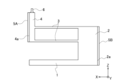
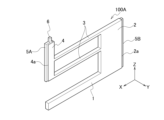
- FIG. 1 is a perspective view of a probe according to the first embodiment.
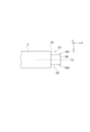
- FIG. 2 is a side view of the probe according to the first embodiment.
- FIG. 3 is an explanatory diagram showing the positional relationship between the perimeter and the protrusions of the support member.
- FIG. 4A is a front view showing a schematic view of a probe inserted into an opening formed in two guide plates of a fixing jig.
- FIG. 4B is a side view showing a state in which the probe is inserted into the openings formed in the two guide plates of the fixture.
- FIG. 4C is a plan view showing a state in which the probes are inserted into the openings formed in the two guide plates of the fixture.
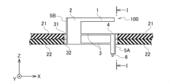
- FIG. 5A is a front view that typically illustrates a state of the probe within the opening when the first guide plate is slid.
- FIG. 5B is a side view that typically illustrates a state of the probe within the opening when the first guide plate is slid.
- FIG. 5C is a plan view that illustrates a state of the probe in the opening when the first guide plate is slid.
- FIG. 6 is an explanatory diagram showing in detail the positional relationship between the support member and the opening when a probe according to a comparative example is used.
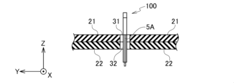
- FIG. 7 is an explanatory diagram showing in detail the positional relationship between the support member and the opening when the probe according to the embodiment is used.
- FIG. 8 is a perspective view of a probe according to a first modified example.
- FIG. 9 is a side view of a probe according to a first modified example.
- FIG. 10 is a side view of a probe according to a second modified example.
- FIG. 11 is a side view of a probe according
- Fig. 1 is a perspective view showing the configuration of a probe according to a first embodiment of the present invention
- Fig. 2 is a side view thereof.
- a probe 100 according to the first embodiment includes a foot portion 1, a support member 2, two arm members 3, and a tip member 4.
- the longitudinal direction of the foot portion 1 is defined as the X-axis direction, the thickness direction of the probe 100 as the Y-axis direction, and the direction perpendicular to the X-Y plane as the Z-axis direction.
- the probe 100 is formed from a conductive flat plate having a thickness t1 (first plate thickness).
- the material of the probe 100 is, for example, a Ni-B (nickel boron) alloy.
- the foot portion 1 has an elongated shape extending in the X-axis direction, and one end of the foot portion 1 is connected to one end of the support member 2 that extends in the Z-axis direction perpendicular to the longitudinal direction of the foot portion 1.
- the Z-axis direction is the first direction in which the support member 2 extends.
- One end of two arm members 3 extending in the X-axis direction is connected to the other end of the support member 2.
- a tip member 4 extending in the Z-axis direction is connected to the other end of each arm member 3.
- a contact portion 6 is formed at the tip of the tip member 4 in the Z-axis direction.
- the material of the contact portion 6 is, for example, Rh (rhodium).
- the probe 100 inspects the test object by bringing the contact portion 6 formed on the tip member 4 into contact with the electrode terminal of the test object.
- the outer periphery 4a of the tip member 4 is formed with a protrusion 5A extending along the Z-axis direction.
- the outer periphery 2a of the support member 2 is formed with a protrusion 5B extending along the Z-axis direction. That is, the protrusions 5A and 5B are arranged parallel to each other.
- the surface (outer surface) of each of the protrusions 5A and 5B is formed into a smooth flat shape.
- the width t2 of each of the protrusions 5A and 5B in the Y-axis direction is narrower than the thickness t1 (first plate thickness) of the probe 100.
- the protrusions 5A and 5B can be formed, for example, from the same Rh (rhodium) as the contact portion 6.
- Figure 3 is an explanatory diagram showing the positional relationship between the outer periphery 2a of the support member 2 and the protrusion 5B.
- the center of the outer periphery 2a and the center of the protrusion 5B coincide with the center line CL. Therefore, the side surfaces 5B1, 5B2 in the Y-axis direction of the protrusion 5B have spatial regions Q1, Q2 formed by the step between them and the support member 2.
- the spatial regions Q1, Q2 it is possible to avoid interference between the arc-shaped corner portion R1, which will be described later, and the support member 2 and the tip member 4.
- the centers of the protrusions 5A and 5B and the center of the contact portion 6 are approximately aligned with the center line in the X-axis direction.
- the width t2 of the protrusions 5A and 5B in the Y-axis direction and the width of the contact portion 6 in the Y-axis direction are approximately aligned.
- the center of the contact portion 6 in the thickness direction is aligned with the center of the protrusions 5A and 5B in the thickness direction.
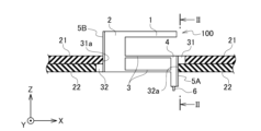
- Figures 4A to 4C are explanatory diagrams that show the appearance of the probe inserted into the fixture, with Figure 4A being a side view, Figure 4B being a cross-sectional view taken along line II, and Figure 4C being a plan view.
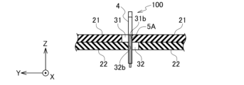
- Figures 5A to 5C are explanatory diagrams that show the appearance of the first guide plate being slid relative to the second guide plate, with Figure 5A being a side view, Figure 5B being a cross-sectional view taken along line II-II, and Figure 5C being a plan view.
- the fixing jig has a first guide plate 21 and a second guide plate 22, and the guide plates 21, 22 are arranged in a stacked manner. Also, as shown in Figure 4C, in the initial state, the opening 31 formed in the first guide plate 21 and the opening 32 formed in the second guide plate 22 are aligned in a plan view (Z-axis direction).
- each opening 31, 32 is rectangular, with the four corners formed in an arc shape.
- Each opening 31, 32 is slightly larger in size than the cross-sectional area of the probe. Therefore, in the initial state, as shown in FIG. 4A and FIG. 4B, it is possible to easily insert the probe 100 into the opening 31, 32.
- the first guide plate 21 When positioning the probe 100, the first guide plate 21 is slid relative to the second guide plate 22 from the state shown in Figures 4A to 4C. Specifically, by sliding the first guide plate 21 in the X-axis direction, the side surface 31a of the opening 31 comes into contact with the protrusion 5B as shown in Figure 5A, and the probe 100 moves in the X-axis direction (to the right in Figure 5A). This causes the side surface 32a of the opening 32 to come into contact with the protrusion 5A. As a result, the probe 100 is restrained in the X-axis direction. In other words, the probe 100 can be positioned in the X-axis direction.
- the side surface 31b of the opening 31 comes into contact with the sides of the support member 2 and the tip member 4 as shown in FIG. 5B, and the probe 100 slides in the Y-axis direction (leftward in FIG. 5A).
- the side surface 32b of the opening 32 comes into contact with the sides of the support member 2 and the tip member 4.
- the probe 100 is restrained in the Y-axis direction. In other words, the probe 100 can be positioned in the Y-axis direction.
- the opening 31 slides a small distance in the X-axis direction and the Y-axis direction relative to the opening 32, so that the probe 100 can be positioned on the XY plane.
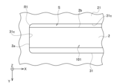
- FIG. 6 is an explanatory diagram showing the positional relationship when a probe 101 (comparative example) that does not have the protrusions 5A and 5B shown in Figs. 1 and 2 is used. As shown in Fig. 6, the probe 101 slides in the X-axis direction (left direction in the figure), so that the outer edge 2a of the support member 2 and the inner surface 31c of the opening 31 come into surface contact.
- the corner portion R1 of the opening 31 is formed in an arc shape, so that the side surface 2b of the support member 2 and the corner portion R1 interfere with each other. Therefore, the side surface 2b and the inner surface 31c of the opening 31 cannot come into surface contact with each other, and a space S is generated. As a result, the probe 101 cannot be positioned accurately.
- FIG. 7 is an explanatory diagram showing the positional relationship when the probe 100 (this embodiment) shown in FIGS. 1 and 2 is used.
- the protrusion 5B formed on the outer edge 2a of the support member 2 comes into surface contact with the inner surface 31c of the opening 31.
- spatial regions Q1 and Q2 are formed on the sides of the protrusion 5B, interference between the side surface 2b of the support member 2 and the corner portion R1 can be avoided even when the probe 100 is slid in the Y-axis direction (upward in the figure). This ensures that the side surface 2b of the support member 2 and the inner surface 31c of the opening 31 can be in surface contact with each other, and thus makes it possible to position the probe 100 in an accurate position.
- FIG. 7 describes the relationship between the protrusion 5B formed on the support member 2 and the openings 31, 32, the same applies to the protrusion 5A formed on the tip member 4. Therefore, even if the corners R1 of the openings 31, 32 are formed in an arc shape, the side surfaces of the support member 2 and the tip member 4 can be reliably brought into contact with the inner surfaces of the openings 31, 32.
- the probe 100 includes a foot portion 1 having an elongated shape, a flat support member 2 connected to one end of the foot portion 1, extending in a first direction (Z-axis direction) and having a thickness t1 (first plate thickness), an arm member 3 having one end connected to the support member 2 and extending in the longitudinal direction of the foot portion 1, a flat tip member 4 connected to the other end of the arm member 3, extending in the first direction and having a first plate thickness, and a contact portion 6 protruding from the tip member 4 in the first direction.
- Protrusions 5A and 5B narrower than the first plate thickness are formed on the outer periphery 2a of the support member 2 and the outer periphery 4a of the tip member 4 along the first direction.
- the support member 2 and tip member 4 of the probe 100 can be reliably brought into surface contact with the inner surfaces of the openings 31, 32 of each guide plate 21, 22. This makes it possible to accurately position the probe 100 even when using guide plates 21, 22 that have openings 31, 32 with arc-shaped corners.
- the material forming the contact portion 6 and the material forming the protrusions 5A and 5B are the same (e.g., Rh), so by forming a pattern using photolithography, it is possible to generate the protrusions 5A and 5B in a simple manner.
- the surfaces of the protrusions 5A, 5B are formed into a smooth, flat shape, so that the protrusions 5A, 5B can be reliably brought into surface contact with the inner surfaces of the openings 31, 32, improving the positioning accuracy of the probe 100.
- the center of the support member 2 and the center of the protrusion 5B coincide, and the center of the tip member 4 and the center of the protrusion 5A coincide, so that the spatial region Q1 can be secured to the same extent on the left and right, making it possible to further improve the positioning accuracy of the probe 100.
- the stress applied when the contact portion 6 contacts the element under test can be stably transmitted in the Z-axis direction.
- the protrusions 5A and 5B are formed of a material harder than the base material of the probe 1, and the arrangement of the protrusions 5A and 5B is offset from the center axis of the contact portion 6 in the X-axis direction, it is possible that the protrusions will bend in the X-axis direction due to the stress acting during the inspection.
- the probe having the shape shown in Figs. 1 and 2 is used as an example, but the probe according to the present invention is not limited to the shape shown in Figs. 1 and 2.
- the present invention can be applied to a probe having three or more arm members 3.
- the contact portion 6 and the protrusion portion 5A are formed from the same material, for example, Rh. Therefore, the contact portion 6 and the protrusion portion 5A can be formed simultaneously by photolithography, which can reduce the labor and cost during manufacturing.
- Fig. 10 is a side view of a probe 100B according to a second modification.
- the protrusion 5A formed on the outer periphery 4a of the tip member 4 is formed shorter than the probe 100 shown in Fig. 2.
- the material for forming the protrusion 5A can be reduced, making it possible to reduce costs.
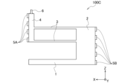
- Fig. 11 is a side view of a probe 100C according to a third modified example.
- the probe 100C shown in Fig. 11 has intermittent protrusions 5B formed on the outer periphery 2a of the support member 2.
- this configuration also makes it possible to accurately position the probe 100B even when using guide plates 21, 22 having openings 31, 32 with arc-shaped corners.
- the material required to form the protrusions 5B can be reduced, allowing costs to be reduced.
Landscapes
- Physics & Mathematics (AREA)
- General Physics & Mathematics (AREA)
- Geometry (AREA)
- Measuring Leads Or Probes (AREA)
- Engineering & Computer Science (AREA)
- Computer Hardware Design (AREA)
- Microelectronics & Electronic Packaging (AREA)
- General Engineering & Computer Science (AREA)
Priority Applications (3)
| Application Number | Priority Date | Filing Date | Title |
|---|---|---|---|
| CN202480036224.XA CN121241261A (zh) | 2023-06-01 | 2024-05-23 | 探测器 |
| KR1020257039040A KR20260003757A (ko) | 2023-06-01 | 2024-05-23 | 프로브 |
| US19/398,492 US20260079179A1 (en) | 2023-06-01 | 2025-11-24 | Probe |
Applications Claiming Priority (2)
| Application Number | Priority Date | Filing Date | Title |
|---|---|---|---|
| JP2023-090723 | 2023-06-01 | ||
| JP2023090723A JP2024172768A (ja) | 2023-06-01 | 2023-06-01 | プローブ |
Related Child Applications (1)
| Application Number | Title | Priority Date | Filing Date |
|---|---|---|---|
| US19/398,492 Continuation US20260079179A1 (en) | 2023-06-01 | 2025-11-24 | Probe |
Publications (1)
| Publication Number | Publication Date |
|---|---|
| WO2024247885A1 true WO2024247885A1 (ja) | 2024-12-05 |
Family
ID=93657947
Family Applications (1)
| Application Number | Title | Priority Date | Filing Date |
|---|---|---|---|
| PCT/JP2024/019035 Ceased WO2024247885A1 (ja) | 2023-06-01 | 2024-05-23 | プローブ |
Country Status (6)
| Country | Link |
|---|---|
| US (1) | US20260079179A1 (https=) |
| JP (1) | JP2024172768A (https=) |
| KR (1) | KR20260003757A (https=) |
| CN (1) | CN121241261A (https=) |
| TW (1) | TWI880760B (https=) |
| WO (1) | WO2024247885A1 (https=) |
Citations (6)
| Publication number | Priority date | Publication date | Assignee | Title |
|---|---|---|---|---|
| JP2010261718A (ja) * | 2009-04-29 | 2010-11-18 | Japan Electronic Materials Corp | プローブ、複数のプローブが実装されたプローブカード、およびプローブカードにプローブを実装する際のプローブの位置決め方法 |
| JP2011027538A (ja) * | 2009-07-24 | 2011-02-10 | Japan Electronic Materials Corp | アライメントマークを設けたプローブ、およびアライメントマークが設けられた複数のプローブが実装されたプローブカード |
| JP2012042329A (ja) * | 2010-08-19 | 2012-03-01 | Micronics Japan Co Ltd | プローブカード |
| JP2020165775A (ja) * | 2019-03-29 | 2020-10-08 | 株式会社日本マイクロニクス | プローブカード |
| JP2023520244A (ja) * | 2020-04-03 | 2023-05-16 | ファイコム カンパニー リミテッド | プローブカード製造用治具、これを含むプローブ整列システム、およびこれを用いて製造されたプローブカード |
| WO2023090062A1 (ja) * | 2021-11-22 | 2023-05-25 | 株式会社日本マイクロニクス | プローブ格納治具、プローブ格納システムおよびプローブ格納方法 |
Family Cites Families (4)
| Publication number | Priority date | Publication date | Assignee | Title |
|---|---|---|---|---|
| JP4932499B2 (ja) * | 2005-01-14 | 2012-05-16 | 株式会社日本マイクロニクス | 通電試験用プローブ |
| US8970238B2 (en) * | 2011-06-17 | 2015-03-03 | Electro Scientific Industries, Inc. | Probe module with interleaved serpentine test contacts for electronic device testing |
| WO2014087906A1 (ja) * | 2012-12-04 | 2014-06-12 | 日本電子材料株式会社 | 電気的接触子 |
| JP7443017B2 (ja) | 2019-10-17 | 2024-03-05 | 株式会社日本マイクロニクス | 検査プローブ、検査プローブの製造方法および検査装置 |
-
2023
- 2023-06-01 JP JP2023090723A patent/JP2024172768A/ja active Pending
-
2024
- 2024-05-23 WO PCT/JP2024/019035 patent/WO2024247885A1/ja not_active Ceased
- 2024-05-23 KR KR1020257039040A patent/KR20260003757A/ko active Pending
- 2024-05-23 CN CN202480036224.XA patent/CN121241261A/zh active Pending
- 2024-05-29 TW TW113119874A patent/TWI880760B/zh active
-
2025
- 2025-11-24 US US19/398,492 patent/US20260079179A1/en active Pending
Patent Citations (6)
| Publication number | Priority date | Publication date | Assignee | Title |
|---|---|---|---|---|
| JP2010261718A (ja) * | 2009-04-29 | 2010-11-18 | Japan Electronic Materials Corp | プローブ、複数のプローブが実装されたプローブカード、およびプローブカードにプローブを実装する際のプローブの位置決め方法 |
| JP2011027538A (ja) * | 2009-07-24 | 2011-02-10 | Japan Electronic Materials Corp | アライメントマークを設けたプローブ、およびアライメントマークが設けられた複数のプローブが実装されたプローブカード |
| JP2012042329A (ja) * | 2010-08-19 | 2012-03-01 | Micronics Japan Co Ltd | プローブカード |
| JP2020165775A (ja) * | 2019-03-29 | 2020-10-08 | 株式会社日本マイクロニクス | プローブカード |
| JP2023520244A (ja) * | 2020-04-03 | 2023-05-16 | ファイコム カンパニー リミテッド | プローブカード製造用治具、これを含むプローブ整列システム、およびこれを用いて製造されたプローブカード |
| WO2023090062A1 (ja) * | 2021-11-22 | 2023-05-25 | 株式会社日本マイクロニクス | プローブ格納治具、プローブ格納システムおよびプローブ格納方法 |
Also Published As
| Publication number | Publication date |
|---|---|
| CN121241261A (zh) | 2025-12-30 |
| US20260079179A1 (en) | 2026-03-19 |
| KR20260003757A (ko) | 2026-01-07 |
| TWI880760B (zh) | 2025-04-11 |
| TW202503280A (zh) | 2025-01-16 |
| JP2024172768A (ja) | 2024-12-12 |
Similar Documents
| Publication | Publication Date | Title |
|---|---|---|
| JP4579361B2 (ja) | 接触子組立体 | |
| JP6908133B2 (ja) | プローブピン、検査治具、検査ユニットおよび検査装置 | |
| US6575767B2 (en) | Contact pin assembly, contact pin assembly manufacturing method, contact pin assembling structure, contact pin assembling structure manufacturing method, and socket for electrical parts | |
| JP6627655B2 (ja) | ソケット | |
| CN100392409C (zh) | 探头、探头装配方法 | |
| TW201839408A (zh) | 電子裝置的測試設備的探針卡 | |
| US20240361352A1 (en) | Test socket and assembly device thereof | |
| JP6699812B1 (ja) | プローブピン、検査治具、検査ユニットおよび検査装置 | |
| JP5588851B2 (ja) | 電気的接続装置及びその製造方法 | |
| JP7471778B2 (ja) | プローブカード | |
| WO2024247885A1 (ja) | プローブ | |
| KR20240056419A (ko) | 전기적 접촉자, 전기적 접속 구조 및 전기적 접속 장치 | |
| TW202507284A (zh) | 用於針式裝置引線的電氣測試接觸端子 | |
| CN101506665A (zh) | 导电性接触件组件 | |
| KR101680319B1 (ko) | 액정 패널 테스트용 프로브 블록 | |
| TWI870265B (zh) | 電性連接裝置之製造輔具及電性連接裝置之製造方法 | |
| WO2024209766A1 (ja) | プローブおよび電気的接続装置の製造方法 | |
| TWI917929B (zh) | 測試插座及其組裝裝置 | |
| TWI919138B (zh) | 探針及電性連接裝置 | |
| CN110196344B (zh) | 探针组件 | |
| JP2012242299A (ja) | 電気的接触子ユニット | |
| JP2000346877A (ja) | コンタクトプローブとその製造方法、および前記コンタクトプローブを用いたプローブ装置とその製造方法 | |
| TW202540679A (zh) | 評估裝置 | |
| JP2010156700A (ja) | 接触子及びこれを用いた接触子組立体 | |
| JPH07130800A (ja) | プローブカード |
Legal Events
| Date | Code | Title | Description |
|---|---|---|---|
| 121 | Ep: the epo has been informed by wipo that ep was designated in this application |
Ref document number: 24815369 Country of ref document: EP Kind code of ref document: A1 |
|
| ENP | Entry into the national phase |
Ref document number: 1020257039040 Country of ref document: KR Free format text: ST27 STATUS EVENT CODE: A-0-1-A10-A15-NAP-PA0105 (AS PROVIDED BY THE NATIONAL OFFICE) |
|
| WWE | Wipo information: entry into national phase |
Ref document number: KR1020257039040 Country of ref document: KR |
|
| NENP | Non-entry into the national phase |
Ref country code: DE |
|
| WWE | Wipo information: entry into national phase |
Ref document number: 11202507953Q Country of ref document: SG |
|
| WWP | Wipo information: published in national office |
Ref document number: 11202507953Q Country of ref document: SG |