WO2024247879A1 - 情報処理方法、情報処理システム、及びプログラム - Google Patents
情報処理方法、情報処理システム、及びプログラム Download PDFInfo
- Publication number
- WO2024247879A1 WO2024247879A1 PCT/JP2024/019018 JP2024019018W WO2024247879A1 WO 2024247879 A1 WO2024247879 A1 WO 2024247879A1 JP 2024019018 W JP2024019018 W JP 2024019018W WO 2024247879 A1 WO2024247879 A1 WO 2024247879A1
- Authority
- WO
- WIPO (PCT)
- Prior art keywords
- information
- information processing
- phase diagram
- processing system
- image
- Prior art date
- Legal status (The legal status is an assumption and is not a legal conclusion. Google has not performed a legal analysis and makes no representation as to the accuracy of the status listed.)
- Ceased
Links
Images


Classifications
-
- G—PHYSICS
- G16—INFORMATION AND COMMUNICATION TECHNOLOGY [ICT] SPECIALLY ADAPTED FOR SPECIFIC APPLICATION FIELDS
- G16C—COMPUTATIONAL CHEMISTRY; CHEMOINFORMATICS; COMPUTATIONAL MATERIALS SCIENCE
- G16C20/00—Chemoinformatics, i.e. ICT specially adapted for the handling of physicochemical or structural data of chemical particles, elements, compounds or mixtures
- G16C20/50—Molecular design, e.g. of drugs
-
- G—PHYSICS
- G16—INFORMATION AND COMMUNICATION TECHNOLOGY [ICT] SPECIALLY ADAPTED FOR SPECIFIC APPLICATION FIELDS
- G16C—COMPUTATIONAL CHEMISTRY; CHEMOINFORMATICS; COMPUTATIONAL MATERIALS SCIENCE
- G16C20/00—Chemoinformatics, i.e. ICT specially adapted for the handling of physicochemical or structural data of chemical particles, elements, compounds or mixtures
- G16C20/30—Prediction of properties of chemical compounds, compositions or mixtures
-
- G—PHYSICS
- G16—INFORMATION AND COMMUNICATION TECHNOLOGY [ICT] SPECIALLY ADAPTED FOR SPECIFIC APPLICATION FIELDS
- G16C—COMPUTATIONAL CHEMISTRY; CHEMOINFORMATICS; COMPUTATIONAL MATERIALS SCIENCE
- G16C20/00—Chemoinformatics, i.e. ICT specially adapted for the handling of physicochemical or structural data of chemical particles, elements, compounds or mixtures
- G16C20/40—Searching chemical structures or physicochemical data
-
- G—PHYSICS
- G16—INFORMATION AND COMMUNICATION TECHNOLOGY [ICT] SPECIALLY ADAPTED FOR SPECIFIC APPLICATION FIELDS
- G16C—COMPUTATIONAL CHEMISTRY; CHEMOINFORMATICS; COMPUTATIONAL MATERIALS SCIENCE
- G16C20/00—Chemoinformatics, i.e. ICT specially adapted for the handling of physicochemical or structural data of chemical particles, elements, compounds or mixtures
- G16C20/70—Machine learning, data mining or chemometrics
-
- G—PHYSICS
- G16—INFORMATION AND COMMUNICATION TECHNOLOGY [ICT] SPECIALLY ADAPTED FOR SPECIFIC APPLICATION FIELDS
- G16C—COMPUTATIONAL CHEMISTRY; CHEMOINFORMATICS; COMPUTATIONAL MATERIALS SCIENCE
- G16C20/00—Chemoinformatics, i.e. ICT specially adapted for the handling of physicochemical or structural data of chemical particles, elements, compounds or mixtures
- G16C20/80—Data visualisation
-
- G—PHYSICS
- G16—INFORMATION AND COMMUNICATION TECHNOLOGY [ICT] SPECIALLY ADAPTED FOR SPECIFIC APPLICATION FIELDS
- G16C—COMPUTATIONAL CHEMISTRY; CHEMOINFORMATICS; COMPUTATIONAL MATERIALS SCIENCE
- G16C60/00—Computational materials science, i.e. ICT specially adapted for investigating the physical or chemical properties of materials or phenomena associated with their design, synthesis, processing, characterisation or utilisation
Definitions
- This disclosure relates to technology for displaying phase diagrams of multi-element compounds.
- phase diagram is a "map" for materials discovery. By looking at a phase diagram, users can easily understand what synthesis conditions (composition, raw materials, temperature, pressure, etc.) are necessary to synthesize the target material. Even for materials for which no experimental reports have been published before, predicting the phase diagram using first-principles calculations or machine learning prediction models can lead to the discovery of new highly functional materials.
- Patent Document 1 discloses a surface analysis device that performs phase analysis using a phase diagram.
- This disclosure provides an information processing method and the like that can output a visually easy-to-recognize phase diagram for multi-element compounds.
- An information processing method is an information processing method executed by a computer, and includes the steps of acquiring a two-dimensional phase diagram having a target compound composed of four or more elements and two or three types of substances as vertices, and outputting the acquired phase diagram, in which at least one of the two or three types of substances is a compound composed of at least two of the four or more elements.
- this comprehensive or specific aspect may be realized by an apparatus, a system, an integrated circuit, a computer program, or a computer-readable recording medium, or may be realized by any combination of a method, an apparatus, a system, an integrated circuit, a computer program, and a computer-readable recording medium.
- the computer-readable recording medium includes, for example, a non-volatile recording medium such as a CD-ROM (Compact Disc-Read Only Memory).
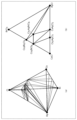
- FIG. 1 is a diagram showing an example of a phase diagram of a ternary compound consisting of three types of elements.
- FIG. 2 is a diagram showing an example of a phase diagram of a quaternary compound consisting of four types of elements.
- FIG. 3 is a diagram showing an example of a state diagram before and after the reduction.
- FIG. 4 is a diagram showing another example of a state diagram before and after the reduction.
- FIG. 5 is a block diagram showing an overall configuration including an information processing system according to the first embodiment.
- FIG. 6 is a diagram showing an example of an image displayed on the display unit in the first embodiment.
- FIG. 7 is a diagram showing an example of a second image displayed on the display unit in the first embodiment.
- FIG. 8 is a diagram showing an example of a third image displayed on the display unit in the first embodiment.
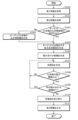
- FIG. 9 is a flowchart showing an operation example of the information processing system according to the first embodiment.
- FIG. 10 is a diagram illustrating an example of the second information.
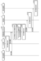
- FIG. 11 is a sequence diagram showing an example of the overall operation including the information processing system according to the first embodiment.
- FIG. 12 is a diagram showing an example of an image displayed on a display unit in the second embodiment.
- FIG. 13 is a flowchart showing an operation example of the information processing system according to the second embodiment.
- FIG. 14 is a sequence diagram showing an example of the overall operation including the information processing system according to the second embodiment.
- FIG. 15 is a diagram showing an example of the second image displayed on the display unit in the third embodiment.
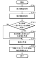
- FIG. 16 is a flowchart showing an operation example of the information processing system according to the third embodiment.
- FIG. 17 is a sequence diagram showing an example of the overall operation including the information processing system according to the third embodiment.
- FIG. 18 is a diagram showing an example of the second image displayed on the display unit in the fourth embodiment.
- FIG. 19 is a diagram showing an example of a reduced-dimensional phase diagram when the target compound is a quinary material.
- a phase diagram plays the role of a "map."
- a phase diagram is a diagram in which multiple substances (elements (atoms) or compounds) that make up a material are at the vertices, and one or more compounds made of these multiple substances are shown on lines.
- the composition of the material and a composition that represents a phase that thermodynamically coexists with the material are displayed.
- compositions that have zero thermodynamic convex hull energy that is, compositions that represent thermodynamically stable phases, are connected by straight lines.
- Phase diagrams are essential when searching for materials because they allow users to easily understand what synthesis conditions (composition, raw materials, temperature, pressure, etc.) are necessary to synthesize the target material. Even for materials for which no experimental reports have been published before, predicting the phase diagram using first-principles calculations or machine learning prediction models can lead to the discovery of new highly functional materials.
- FIG. 1 is a diagram showing an example of a phase diagram of a ternary compound consisting of three elements.
- the three elements are silver (Ag), chlorine (Cl), and cesium (Cs).
- FIG. 2 is a diagram showing an example of a phase diagram of a quaternary compound consisting of four elements.
- the four elements are silver, chlorine, cesium, and bismuth (Bi).
- the phase diagram of a ternary compound consisting of three elements is an equilateral triangle and is represented on a two-dimensional plane, so it is easy for humans to visually recognize it. Phase diagrams represented on a two-dimensional plane as shown in FIG.
- phase diagram of a quaternary compound consisting of four elements is a regular tetrahedron and is represented in three-dimensional space, so it is difficult for humans to visually recognize it compared to a two-dimensional plane.
- phase diagram of a quinary compound consisting of five elements is a regular pentagon and is represented in four-dimensional space, so it is difficult for humans to visually recognize it. This diversification of materials has made it difficult for humans to visually recognize previous phase diagrams, limiting the design and development of multi-element compounds.
- the information processing method is an information processing method executed by a computer, which has a target compound composed of four or more elements, and includes the steps of acquiring a two-dimensional phase diagram with two or three types of substances as vertices, and outputting the acquired phase diagram, where at least one of the two or three types of substances is a compound composed of at least two of the four or more elements.
- the method further includes a step of acquiring a multi-element phase diagram having the target compound and expressed in three or more dimensions with each of the four or more elements as a vertex, and in the step of acquiring the phase diagram, at least one of the phase diagrams may be extracted from the acquired multi-element phase diagram.
- the multi-element state diagram may have a plurality of compounds each formed by combining two or more elements from among the four or more elements, and in the step of acquiring the state diagram, the state diagram may be extracted in which at least one compound from among the plurality of compounds is arranged at a position other than a vertex.
- the information processing system includes a display control unit that causes a display unit to display a second image showing a two-dimensional state diagram generated based on the input first information after a first image that accepts input of first information regarding a target compound composed of four or more elements is displayed on the display unit, the state diagram having three or more vertices, the target compound and a plurality of compounds each composed of at least two of the four or more elements are arranged on the state diagram, and at least one compound of the plurality of compounds is arranged on at least one of the three or more vertices of the state diagram.
- the state diagram may be one or more state diagrams that are different from each other, and the display control unit may cause the second image showing the one or more state diagrams to be displayed on the display unit.
- the one or more phase diagrams in the second image may be arranged in descending order of the number of compounds included in the phase diagram.
- the display control unit when the display control unit receives a selection of one state diagram from the one or more state diagrams, the display unit may display the second image showing the one selected state diagram.
- the display control unit may cause the display unit to display the second image further including a multi-element phase diagram expressed in three or more dimensions, and the multi-element phase diagram may have each of the four or more elements arranged at a vertex, and the target compound may be arranged at a vertex.
- the display control unit may cause the display unit to display the second image in which a plane or line representing at least one of the state diagrams is superimposed on the multi-element state diagram.
- the one or more phase diagrams are all represented as triangles, and at least one of the shape of the triangles, the materials corresponding to each vertex of the triangles, and the areas of the triangles may be different from each other.
- the display control unit causes the display unit to display, as the first information, the first image for accepting input of a target element contained in the target compound and an image for accepting input of a physical property of the target compound;
- the display unit may be caused to display an image including one or more target compounds containing the target element and the physical properties predicted based on the input target element and the physical properties of the one or more target compounds.
- the display control unit when the display control unit receives a selection of one target compound from the one or more target compounds, the display unit may display the selected one target compound and the second image including an image representing the physical property values of the one target compound.
- the display control unit may cause the display unit to display the second image representing the phase diagram generated based on at least one of the temperature conditions and pressure conditions of the target compound.
- the display control unit may cause the display unit to display the second image representing the phase diagram, the second image further having an energy axis indicating the energy of each of the multiple substances included in the phase diagram.
- a program according to a fifteenth aspect of the present disclosure has a target compound composed of four or more elements, and causes a computer to execute the steps of acquiring a two-dimensional phase diagram with two or three substances as vertices, and outputting the acquired phase diagram, where at least one of the two or three substances is a compound composed of at least two of the four or more elements.
- the characteristic processes included in the information processing method disclosed herein can be realized as a computer program that causes a computer to execute the processes.
- a computer program can be distributed on a non-transitory computer-readable recording medium such as a CD-ROM or via a communication network such as the Internet.
- the reduction of the dimensionality of the phase diagram of a multi-element compound needs to be performed so that the reduced dimensional phase diagram contains information necessary for material design.
- the information necessary for material design corresponds to the phases that coexist with the target phase and the raw material phases in the phase diagram.
- FIG. 3 is a diagram showing an example of a state diagram before reduction and a state diagram after reduction.
- FIG. 3(a) shows a state diagram before reduction represented in a three-dimensional space with Cs, Ag, Bi, and Cl as vertices.
- FIG. 3(b) is a diagram cutting out the hatched plane in FIG. 3(a), showing a state diagram after reduction represented in a two-dimensional plane with CsCl, AgCl, and BiCl 3 as vertices.
- FIG. 4 is a diagram showing another example of a state diagram before reduction and a state diagram after reduction.
- FIG. 4(a) shows a state diagram before reduction represented in a three-dimensional space with Cs, Ag, Bi, and Cl as vertices.
- FIG. 4B is a diagram cut out from the hatched plane in FIG. 4A, and shows a phase diagram after reduction in dimension, expressed as a two-dimensional plane with CsCl, Ag, and BiCl3 as vertices.
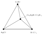
- Fig. 19 is a diagram showing an example of a reduced-dimensional phase diagram when the target compound is a quinary material.
- Fig. 19 shows a reduced-dimensional phase diagram expressed on a two-dimensional plane with CsBr, AgCl, and BiCl3 as vertices.
- the phases coexisting with the target material Cs2AgBiCl6 are Cs3Bi2Cl9 , Cs3BiCl6 , CsAgCl2 , CsAgCl3 , and AgCl.
- the phase diagram after the reduction in dimension shown in FIG. 3 ( b ) all of the information on the phases coexisting with the above - mentioned Cs2AgBiCl6 , namely Cs3Bi2Cl9 , Cs3BiCl6 , CsAgCl2 , CsAgCl3 , and AgCl, is extracted. Therefore, by looking at the phase diagram after reduction in dimension shown in FIG. 3B, a user can visually grasp in which phase the target material Cs 2 AgBiCl 6 coexists, which may facilitate material design.
- the reduced-dimensional phase diagram shown in (b) of Fig. 4 lacks information on the target material, Cs 2 AgBiCl 6. For this reason, even if a user looks at the reduced-dimensional phase diagram shown in (b) of Fig. 4, he or she cannot visually grasp in which phase the target material, Cs 2 AgBiCl 6 , coexists, which may make material design difficult.
- phase diagram of a multi-element compound when reducing the dimensionality of a phase diagram of a multi-element compound, by reducing the dimensionality of the phase diagram so that it is expressed in two dimensions including the target compound and the phase that coexists with the target compound or the raw material phase, it becomes easier for users to understand the phase diagram of the multi-element compound.
- each of the embodiments described below shows a comprehensive or specific example of the present disclosure.
- the numerical values, shapes, materials, components, the arrangement and connection of the components, steps, and the order of steps shown in each of the following embodiments are merely examples and are not intended to limit the present disclosure.
- those components that are not described in an independent claim that shows the highest concept are described as optional components.
- each figure is a schematic diagram and is not necessarily a precise illustration.
- the same components are given the same reference numerals in each figure.
- the information processing system may be configured so that all components are included in one computer, or may be configured as a system in which multiple components are distributed across multiple computers.
- FIG. 5 is a block diagram showing an overall configuration including an information processing system 100 according to the first embodiment.
- the information processing system 100 is configured as a computer such as a personal computer or a server. That is, the information processing system 100 may be realized, for example, by cloud computing. In the first embodiment, the information processing system 100 will be described as being a stationary computer.
- the information processing system 100 includes a first acquisition unit 11, a second acquisition unit 12, a generation unit 13, and an output unit 14.
- an input unit 2, a display control unit 30, a display unit 3, a first storage unit 4, and a second storage unit 5 are connected to the information processing system 100.
- the input unit 2, the display control unit 30, and the display unit 3 are configured by an information terminal used by a user, such as a smartphone, a tablet terminal, or a personal computer.
- the input unit 2, the display control unit 30, the first storage unit 4, and the second storage unit 5 may all be connected to the information processing system 100 via a LAN (Local Area Network) or the like, or may be connected to the information processing system 100 via a network such as the Internet.
- LAN Local Area Network
- the input unit 2 is an input interface that accepts user input, and is composed of, for example, a keyboard, a touch sensor, a touchpad, or a mouse.
- the input unit 2 accepts input operations by the user, and outputs a signal corresponding to the input operation to the information processing system 100.
- the display unit 3 and the input unit 2 are configured independently of each other, but they may be configured integrally, such as a touch panel.
- the information processing system 100 does not include a display unit 3 and an input unit 2, but may include these.
- the input unit 2 accepts input of first information regarding a target compound composed of four or more elements.
- the target compound may be, for example, a compound desired by the user, or may simply be a compound to be output.
- the first information is, for example, composition information indicating the composition of the target compound.
- the first information may be, for example, element information indicating the elements contained in the target compound, composition ratio information indicating the composition ratio of multiple elements contained in the target compound, or crystal structure information indicating the crystal structure of the target compound.
- the first information is composition information.
- the display control unit 30 causes the display unit 3 to display images, etc., based on the information output from the output unit 14 of the information processing system 100.
- the display unit 3 displays images and the like under the control of the display control unit 30.
- the display unit 3 is, for example, a liquid crystal display, a plasma display, or an organic EL (Electro-Luminescence) display, but is not limited to these.
- the first storage unit 4 is a recording medium for storing the state diagram database.
- the recording medium is, for example, a hard disk drive, a RAM (Random Access Memory), a ROM (Read Only Memory), or a semiconductor memory. Note that such a recording medium may be either volatile or non-volatile.
- the phase diagram database includes compound data related to compounds.
- Examples of compound data stored in the phase diagram database include thermodynamic data of elemental elements (e.g., Cs, Ag, Bi, or Cl, etc.) and thermodynamic data of compounds (e.g., CsCl, AgCl, BiCl 3 , or Cs 2 AgBiCl 6 , etc.).
- the thermodynamic data is free energy of an element or compound at any temperature and any pressure.
- the thermodynamic data stored in the phase diagram database may include experimentally observed data, or may include data predicted by a simulation such as a first-principles calculation.
- the compound data may include physical property information indicating the physical properties of the compound, such as structural information, energy information, band gap, volume, ionic conductivity, or dielectric constant.
- the structural information may include, for example, the composition, crystal system, space group, lattice constant, or atomic coordinates of the compound.
- the energy information may include, for example, thermodynamic convex hull energy, or formation energy.
- the second storage unit 5 is a recording medium for storing third information indicating state diagram data selected by the user from one or more state diagram data generated by the generation unit 13.
- the recording medium is, for example, a hard disk drive, a RAM (Random Access Memory), a ROM (Read Only Memory), or a semiconductor memory. Note that such a recording medium may be either volatile or non-volatile.
- the first acquisition unit 11 acquires first information on a target compound such as Cs 2 AgBiCl 6.
- the first acquisition unit 11 is an entity that executes the step of acquiring first information in the information processing method of the present disclosure. Specifically, the first acquisition unit 11 acquires first information input by a user via the input unit 2. As will be described later, the user performs an operation to input the first information while viewing a first image displayed on the display unit 3 that accepts input of the first information.
- the second acquisition unit 12 acquires second information on the composition of the target compound from the first storage unit 4.
- the second acquisition unit 12 is the entity that executes the step of acquiring second information in the information processing method disclosed herein. Specifically, the second acquisition unit 12 reads data on the composition of the target compound indicated by the first information from the first storage unit 4 based on the first information input by the user via the input unit 2, and acquires the read data as the second information.
- the data on the composition of the target compound may include, for example, data on four or more elements that constitute the target compound, and data on a compound constituted by combining two or more elements from among the four or more elements.
- the generating unit 13 generates third information showing one or more phase diagrams based on the first information acquired by the first acquiring unit 11 and the second information acquired by the second acquiring unit 12.
- the generating unit 13 is an entity that executes the step of generating third information in the information processing method disclosed herein.
- Each of the one or more phase diagrams has a target compound, and is a two-dimensional diagram with two or three types of substances (elements or compounds) as vertices. Furthermore, at least one of the two or three types of substances is a compound composed of at least two types of elements out of the four or more types of elements that make up the target compound.
- the generating unit 13 generates (obtains) a multi-element phase diagram showing the target compound based on the first information and the second information.
- the multi-element phase diagram has the target compound and is represented in three or more dimensions with each of the four or more elements constituting the target compound as a vertex.
- the generating unit 13 then extracts at least one phase diagram from the generated (obtained) multi-element phase diagram.
- the generating unit 13 extracts a phase diagram in which at least one compound out of the multiple compounds contained in the multi-element phase diagram is arranged at a position other than a vertex. Details of the processing executed by the generating unit 13 will be described later.
- the output unit 14 outputs the image, etc. to the display control unit 30, thereby displaying the image, etc. on the display unit 3.
- the output unit 14 also outputs the third information generated by the generation unit 13.
- the output unit 14 is the entity that executes the step of outputting the third information in the information processing method disclosed herein. Specifically, the output unit 14 outputs the third information by displaying a second image representing the third information generated by the generation unit 13 on the display unit 3. As described below, the user performs an operation to select the fourth information to be stored in the second storage unit 5 while looking at the second image displayed on the display unit 3.
- Fig. 6 is a diagram showing an image displayed on the display unit 3 in the first embodiment.
- Fig. 6(a) shows an example of a first image displayed on the display unit 3.
- the first image is an image for accepting input of first information.
- the first image includes a first information input area for inputting first information related to a target compound, such as composition information of the target compound (e.g., Cs2AgBiCl6 ), and an execution icon called "Generation”.
- a text box for specifying the composition of the target compound is displayed.
- the user inputs the desired composition of the target compound in the text box and selects the execute icon.
- the first acquisition unit 11 acquires composition information of the target compound as the first information.
- the second acquisition unit 12 acquires data on the composition of the target compound input by the user from the first storage unit 4 as the second information.
- the generation unit 13 in the step of generating the third information generates third information showing one or more phase diagrams based on the first information and the second information.
- the first image may include an input area for specifying the number of state diagrams to be displayed in the second image, which will be described later.
- the second image will display a list of the specified number of state diagrams.
- the first image may include an input area for specifying which database to use to generate the third information.
- the generation unit 13 When the user inputs a database designation in the input area, the generation unit 13 generates the third information using the information stored in the database.
- the multiple databases may include, for example, a database that stores the second information obtained from an experiment, or a database that stores the second information obtained by calculation.
- the database that stores the second information obtained by calculation may include databases with different calculation methods, such as a database that stores the second information obtained using first-principles calculation, or a database that stores the second information obtained by machine learning.
- FIG. 6 shows an example of the second image displayed on the display unit 3.
- the second image is displayed on the display unit 3 after the user selects the execution icon in the first image and the generation unit 13 generates the third information.
- the second image includes a list of one or more (here, nine) state diagrams generated by the generation unit 13, a selection button provided for each of the one or more state diagrams, and an execution icon "Save selected state diagram.”
- the display unit 3 displays a second image including an enlarged image of the selected state diagram and an execution icon "Save state diagram" as shown in FIG. 6(c).
- the white circles in the state diagram represent target compounds, and the black circles represent elements or compounds.
- the user selects the execution icon "Save state diagram” in the image, or selects one of the buttons in the second image shown in FIG. 6(b) and then selects the execution icon "Save selected state diagram".
- fourth information indicating the state diagram selected by the user is stored in the second storage unit 5.
- the fourth information may be stored in the second storage unit 5 as image data of the state diagram, or may be stored in the second storage unit 5 as table data listing the information included in the state diagram.
- the second image may include only one state diagram instead of a list of state diagrams.
- FIG. 7 is a diagram showing an example of the second image displayed on the display unit 3 in the first embodiment.
- the second image includes one of the multiple state diagrams generated by the generation unit 13, a left arrow icon for selecting the previous state diagram, a right arrow icon for selecting the next state diagram, and an execution icon called "Save state diagram".
- the second image includes the state diagram that is ranked first when the multiple state diagrams generated by the generation unit 13 are sorted, and an execution icon called "Save state diagram". In this case, the user cannot select another state diagram.
- the third image shows an example of the third image displayed on the display unit 3 in the first embodiment.
- the third image is displayed on the display unit 3 together with the selected phase diagram after the user selects one of the phase diagrams in the second image.
- the third image may be displayed on the display unit 3 alone.
- the third image includes compound information on the target compound and an execution icon called "Save compound information".
- the compound information displayed as the third image is, for example, structural information, energy information, physical property information showing the physical properties of the compound such as band gap, volume, ionic conductivity, or dielectric constant.
- the structural information may include, for example, the composition, crystal system, space group, lattice constant, or atomic coordinates of the compound.
- the energy information may include, for example, thermodynamic convex hull energy or formation energy.
- FIG. 9 is a flowchart showing an example of the operation of the information processing system 100 according to the first embodiment.
- the first acquisition unit 11 acquires the first information.
- the first information is, for example, composition information of a target compound (for example, Cs 2 AgBiCl 6 ).
- the first information is acquired by the first acquisition unit 11 when the user inputs (selects) the first information using the input unit 2 while viewing the first image displayed on the display unit 3.
- the first information may be acquired by the first acquisition unit 11 when the user inputs original data using the input unit 2 without referring to the first image.
- the second acquisition unit 12 acquires the second information.
- the second information is information on the composition of the target compound.
- the second acquisition unit 12 reads data on the composition of the target compound indicated by the first information from the first storage unit 4, and acquires the read data as the second information.
- FIG. 10 is a diagram showing an example of the second information.
- the example shown in FIG. 10 represents the second information when the target compound is Cs 2 AgBiCl 6.
- the second information includes a composition on the target compound and compound information of the corresponding composition.
- the formation energy of the corresponding composition and the formation entropy of the corresponding composition are compound information.
- the composition is the target compound, an element constituting the target compound (here, Cs, Bi, Cl, etc.), or a compound composed of a combination of two or more elements constituting the target compound (here, CsCl, AgCl, BiCl 3 , etc.).
- the second information may include the total energy of the corresponding composition instead of the formation energy of the corresponding composition.
- the second information includes compound information of the target compound, but may not include compound information of the target compound.
- Step S103 the generation unit 13 executes a process of determining whether or not the acquired second information includes compound information of the target compound indicated by the first information, based on the acquired first information and second information. If the second information does not include compound information of the target compound (step S103: No), the generation unit 13 then executes step S104. On the other hand, if the second information includes compound information of the target compound (step S103: Yes), the generation unit 13 then executes step S105.
- the generating unit 13 executes a process of generating compound information of the target compound based on the acquired first information.
- the compound information is, for example, energy information such as formation energy.
- the generating unit 13 can predict a crystal structure based on, for example, the composition of the target compound, and calculate energy information of the predicted crystal structure by a simulation such as a first-principles calculation.
- the generating unit 13 can also calculate (estimate) the energy information of the predicted crystal structure using, for example, a machine-learned prediction model.
- the prediction model is composed of a graph neural network that takes a graph structure as input.
- graph neural networks include CGCNN (Crystal Graph Convolutional Neural Network) and MEGNet (Material Graph Network).
- MEGNet is a graph neural network that not only uses nodes (junctions/vertices) and edges (branches/sides) as features, but also uses global state quantities that represent the characteristics of the entire target system as features.
- the prediction model is machine-trained using a large number of training datasets so that, when an arbitrary crystal structure is input, the model outputs energy information for that crystal structure.
- the training dataset contains the crystal structure as input data, and the energy information corresponding to that crystal structure as correct answer data.
- the generation unit 13 may calculate (estimate) the energy information of the target compound using a prediction model that has been machine-learned to output the energy information of an arbitrary composition input. After executing step S104, the generation unit 13 executes step S105.
- the generating unit 13 executes a process of generating (obtaining) a multi-element phase diagram showing the target compound based on the acquired first information and second information. For example, the generating unit 13 calculates a thermodynamic convex hull energy from the composition of the compound included in the second information and its formation energy, and searches for a thermodynamically stable compound based on the calculated thermodynamic convex hull energy, thereby generating a multi-element phase diagram showing the target compound. For example, when the composition of the target compound is CuInSe2 , the thermodynamic convex hull energy is expressed by the following formula.
- ⁇ E hull (A) indicates the thermodynamic convex hull energy of the compound "A”
- ⁇ E form (A) indicates the formation energy of the compound "A”.
- ⁇ E hull (A) 0
- ⁇ E hull (A) 0.
- the formation energy of the target compound can be calculated using a first-principles calculation or a machine learning prediction model. Note that, as described in, for example, a paper by Wenhao et al. (S. Wenhao, et al.
- thermodynamic convex hull energy is 0.1 eV or less.
- thermodynamic convex hull energy is an indicator of the synthesis feasibility of a crystal structure.
- the generation unit 13 executes a process of generating combination candidates, which are compounds that can be in a phase coexisting with the target compound, based on the generated multi-element phase diagram.
- combination candidates are compounds that can be in a phase coexisting with the target compound, based on the generated multi-element phase diagram.
- the target compound is Cs2AgBiCl6
- the combination candidates are CsCl, AgCl, etc.
- the generating unit 13 executes a process of generating a state diagram based on the multi-element state diagram and the combination candidates.
- the state diagram referred to here is a state diagram in which the multi-element state diagram is reduced in dimension. Specifically, the generating unit 13 generates, as a state diagram, a plane or a line including the target compound and two combination candidates arbitrarily selected from all combination candidates in the multi-element state diagram.
- Step S108 The generating unit 13 executes a process of determining whether the number of compounds included in the generated phase diagram is equal to or greater than a threshold value.
- the threshold value is, for example, 3, but may be a number greater than 3 or may be appropriately set by the user. If the number of compounds included in the generated phase diagram is equal to or greater than the threshold value (step S108: Yes), the generating unit 13 then executes step S109. On the other hand, if the number of compounds included in the generated phase diagram is less than the threshold value (step S108: No), the generating unit 13 discards the phase diagram and executes step S107 again. In addition, in step S107 again, the generating unit 13 arbitrarily selects two combination candidates after excluding the combination candidates already selected.
- Step S109 The generating unit 13 executes a process of determining whether or not there are other combination candidates that have not yet been selected. If there are other combination candidates (step S109: Yes), the generating unit 13 executes step S107 again. In addition, in the re-execution of step S107, the generating unit 13 arbitrarily selects two combination candidates after excluding the combination candidate that has already been selected. On the other hand, if there are no other combination candidates (step S109: No), the generating unit 13 next executes step S110.
- Step S110 The generation unit 13 executes a process of rearranging the one or more generated phase diagrams.
- the generation unit 13 rearranges the one or more generated phase diagrams in descending order of the number of compounds included in the phase diagrams.
- Step S111 The output unit 14 executes a process of outputting third information indicating one or more state diagrams generated by the generation unit 13.
- the output unit 14 outputs the third information by generating a second image representing the third information generated by the generation unit 13 and displaying the generated second image on the display unit 3.
- FIG. 11 is a sequence diagram showing an example of the overall operation including the information processing system 100 according to the first embodiment.
- Step S201 The input unit 2 accepts an input of the first information.
- the user inputs (selects) the first information using the input unit 2 while viewing the first image displayed on the display unit 3.
- Step S202 The first acquisition unit 11 of the information processing system 100 acquires the first information received by the input unit 2.
- the second acquisition unit 12 of the information processing system 100 reads data on the composition of the target compound indicated by the first information from the first storage unit 4, and acquires the read data as second information.
- Step S203 The generating unit 13 of the information processing system 100 executes a process of generating (obtaining) a multi-element phase diagram showing the target compound based on the acquired first information and second information. Note that between step S202 and step S203, the same process as step S103 and step S104 (see FIG. 9) is executed.
- Step S204 The generating unit 13 of the information processing system 100 generates third information indicating one or more state diagrams. Note that in step S204, the same processes as in steps S106 to S110 (see FIG. 9) are executed.
- Step S205 The display unit 3 displays a second image representing the third information output from the output unit 14 of the information processing system 100.
- the second image is a generated second image.
- Step S206 When the user selects a state diagram to be saved while viewing the second image displayed on the display unit 3, the information processing system 100 provides the fourth information indicating the selected state diagram to the second storage unit 5. As a result, the second storage unit 5 saves the fourth information indicating the state diagram selected by the user.
- a target compound composed of four or more elements can be outputted, and a two-dimensional phase diagram can be outputted with two or three types of substances as vertices.
- a multi-element phase diagram showing a target compound can be reduced in dimension so that the phase diagram is expressed in two dimensions including the target compound and a phase that coexists with the target compound or a phase that is a raw material. Therefore, in the first embodiment, a phase diagram that is easy to visually recognize for a multi-element compound can be outputted, and by looking at the phase diagram, a user can more easily design and develop a target compound that is a multi-element compound.
- an information processing system 200 (see FIG. 14) (information processing method or program) according to a second embodiment of the present disclosure will be described in detail with reference to the drawings.
- the information processing system 200 according to the second embodiment differs from the information processing system 100 according to the first embodiment in that the first acquisition unit 11 acquires element information indicating elements contained in the target compound as the first information, rather than composition information of the target compound. Note that a description of the configuration common to the information processing system 100 according to the first embodiment will be omitted.
- Fig. 12 is a diagram showing an example of an image displayed on the display unit 3 in the second embodiment.
- (a) of Fig. 12 shows an example of a first image displayed on the display unit 3.
- the first image includes a first information input area for inputting first information, which is element information (e.g., Cs, Ag, Bi, Cl, etc.) of the target compound, a property selection area for selecting a property to be predicted, and an execution icon of "perform prediction".
- element information e.g., Cs, Ag, Bi, Cl, etc.
- the first information input area displays a text box for specifying an element contained in the target compound ("target element" in FIG. 12(a)).
- the physical property selection area displays the physical properties of the target compound that can be selected by the user. In the example shown in FIG. 12(a), the user selects band gap as the physical property, but other physical properties may be selectable, for example, from a pull-down menu. Selectable physical properties include band gap, electrical conductivity, ionic conductivity, thermal conductivity, and dielectric constant.
- the user inputs the desired target element in the text box, selects the desired physical property, and then selects the execute icon.
- the first acquisition unit 11 acquires element information of the target compound as the first information.
- the second acquisition unit 12 acquires data on the element input by the user from the first storage unit 4 as the second information.
- the generation unit 13 (in the step of generating the fifth information) predicts one or more target compounds containing the target element based on the first information and the second information, and predicts the physical properties of the predicted target compounds.
- the fifth information is information indicating the one or more target compounds predicted by the generation unit 13, and the physical properties of the one or more target compounds.
- FIG. 12 shows an example of a fourth image displayed on the display unit 3.
- the fourth image is displayed on the display unit 3 after the user selects the execution icon in the first image and the generation unit 13 predicts the physical property information of the predicted target compound.
- the fourth image includes a table showing one or more target compounds predicted by the generation unit 13 and a list of the physical properties (here, band gaps) of the one or more target compounds predicted by the generation unit 13, and an execution icon "Generate phase diagram.”
- the user selects a button corresponding to a desired target compound from among one or more target compounds, and then selects the "Generate phase diagram" execution icon.
- the generation unit 13 then generates one or more phase diagrams for the selected target compound.
- the output unit 14 then outputs third information indicating the one or more phase diagrams generated by the generation unit 13.
- a second image (see FIG. 6(b)) for the target compound selected by the user is displayed on the display unit 3.
- the second image displayed on the display unit 3 here is the same as the second image in the first embodiment, and therefore will not be described.
- (c) of FIG. 12 is an example of a second image including an enlarged image of a state diagram selected by the user, a left arrow icon for selecting the previous state diagram, a right arrow icon for selecting the next state diagram, and an execution icon for "save state diagram.”
- the state diagram reflects a heat map in which the magnitude of a physical property value (here, the band gap) is represented by a shade of gray. The user selects the execution icon for "save state diagram" on the image. Then, fourth information indicating the state diagram selected by the user is saved in the second storage unit 5.
- FIG. 13 is a flowchart showing an example of the operation of the information processing system 200 according to the second embodiment. Below, the process up to outputting the fifth information predicted by the generation unit 13 will be described. The process after the user selects the target compound is the same as steps S101 to S111 (excluding steps S103 and S104) of the information processing system 100 according to the first embodiment, and therefore will not be described here.
- the first acquisition unit acquires the first information.
- the first information is, for example, element information (e.g., Cs, Ag, Bi, or Cl) of the target compound and the physical properties of the target compound.
- the first information is acquired by the first acquisition unit 11 when the user inputs (selects) the first information using the input unit 2 while viewing the first image displayed on the display unit 3. Note that the first information may be acquired by the first acquisition unit 11 when the user inputs original data using the input unit 2 without referring to the first image.
- the second acquisition unit 12 acquires the second information.
- the second information is information related to the composition of the target compound.
- the second acquisition unit 12 reads data related to the composition of the target compound indicated by the first information from the first storage unit 4, and acquires the read data as the second information.
- the second acquisition unit 12 acquires data on the target element and data on a compound consisting of two or more types of target elements as data related to the composition of the target compound.
- Step S303 The generating unit 13 executes a process of determining whether or not to predict a compound not included in the acquired second information based on the acquired first information and second information. Whether or not to predict may be set in advance, or may be appropriately set by the user. If a prediction is to be made (step S303: Yes), the generating unit 13 then executes step S304. On the other hand, if a prediction is not to be made, the generating unit 13 then executes step S305.
- Step S304 The generation unit 13 executes a process of predicting compounds not included in the second information based on the acquired first information and second information.
- the generation unit 13 predicts compounds that are composed of all of the target elements and are not included in the second information.
- the generation unit 13 executes a process of predicting one or more target compounds composed of all the target elements. In other words, the generation unit 13 predicts, as a target compound, a compound composed of all the target elements among the compounds included in the second information. The generation unit 13 also predicts a target compound by predicting a compound not included in the second information that is composed of all the target elements.
- the generating unit 13 executes a process of predicting physical properties (e.g., band gap, etc.) for each of the predicted one or more target compounds.
- the generating unit 13 can predict a crystal structure based on the composition of the predicted target compound, for example, and calculate the physical properties of the predicted crystal structure by a simulation such as a first-principles calculation.
- the generating unit 13 can also calculate (estimate) the physical properties of the predicted crystal structure using, for example, a machine-learned prediction model. Note that, if the physical properties of the predicted target compound are included in the second information, the generating unit 13 may refer to the second information.
- Step S306 The output unit 14 executes a process of outputting the fifth information predicted by the generation unit 13.
- the output unit 14 outputs the fifth information by displaying a fourth image representing the fifth information predicted by the generation unit 13 on the display unit 3.
- FIG. 14 is a sequence diagram showing an example of the overall operation including the information processing system 200 according to the second embodiment.
- the process up to accepting the selection of the target compound by the user will be described.
- the process after the user selects the target compound is the same as steps S202 to S206 in the overall operation including the information processing system 100 according to the first embodiment, so a description thereof will be omitted here.
- Step S401 The input unit 2 accepts an input of the first information.
- the user inputs (selects) the first information using the input unit 2 while viewing the first image displayed on the display unit 3.
- Step S402 The first acquisition unit 11 of the information processing system 200 acquires the first information received by the input unit 2.
- the second acquisition unit 12 of the information processing system 200 reads data on the composition of the target compound indicated by the first information from the first storage unit 4, and acquires the read data as second information.
- Step S403 The generation unit 13 of the information processing system 200 executes a process of predicting the physical properties of each of the one or more predicted target compounds obtained. Note that between step S402 and step S403, the same processes as those in step S303 and step S304 (see FIG. 13) are executed.
- Step S404 The display unit 3 displays a fourth image representing the fifth information output from the output unit 14 of the information processing system 200 .
- Step S405 The input unit 2 accepts the selection of a target compound by the user.
- the user selects a desired target compound using the input unit 2 while viewing the fourth image displayed on the display unit 3.
- the user does not need to specify a desired target compound, but can specify multiple elements to be included in the target compound, thereby outputting a visually easy-to-recognize phase diagram for the target compound composed of the specified multiple elements. Therefore, in the second embodiment, the user can easily design and develop the target compound, which is a multi-element compound, by looking at the output phase diagram.
- an information processing system 300 (see FIG. 17) (information processing method or program) according to a third embodiment of the present disclosure will be described in detail with reference to the drawings.
- the information processing system 300 according to the third embodiment differs from the information processing system 100 according to the first embodiment in that the output unit 14 outputs third information indicating a state diagram taking into account temperature information and pressure information. Note that a description of the configuration common to the information processing system 100 according to the first embodiment will be omitted.
- Fig. 15 shows an example of a second image displayed on the display unit 3 in the third embodiment.
- Fig. 15 shows an example of the second image including an enlarged image of a state diagram selected by a user, a temperature input area for inputting temperature information, a pressure input area for inputting pressure information, and an execution icon for "save the state diagram.”
- the temperature input area displays a bar for specifying the temperature conditions for the target compound and a text box for specifying the temperature conditions.
- the user may specify the temperature conditions using the bar, or may specify the temperature conditions by inputting information into the text box.
- the pressure input area displays a bar for specifying the pressure conditions for the target compound and a text box for specifying the pressure conditions.
- the user may specify the pressure conditions using the bar, or may specify the pressure conditions by inputting information into the text box.
- the generation unit 13 updates the phase diagram based on the input information (at least one of the temperature information and the pressure information). Then, the output unit 14 outputs third information indicating the phase diagram updated by the generation unit 13. As a result, the display unit 3 displays a second image indicating the updated phase diagram.
- the phase diagram displays ABC 2 , which is a compound thermodynamically stable under the specified temperature and pressure environment.
- the phase diagram displays a phase that thermodynamically coexists with the compound ABC 2 by a dashed line. The user selects an execution icon for "save phase diagram" on the image.
- fourth information indicating the phase diagram selected by the user is stored in the second storage unit 5.
- the user can design the synthesis conditions of the target compound by predicting the temperature and pressure range in which the target compound can exist on the phase diagram.
- FIG. 16 is a flowchart showing an example of the operation of the information processing system 300 according to the third embodiment. The following describes the process after the user has specified at least one of the temperature and pressure. The process before that is the same as steps S101 to S111 of the information processing system 100 according to the first embodiment, and therefore will not be described here.
- Step S501 The first acquisition unit 11 acquires at least one of temperature information and pressure information (in FIG. 16 , both temperature information and pressure information are acquired).
- the temperature information is acquired by the first acquisition unit 11 when the user inputs a temperature in the temperature input area using the input unit 2 while viewing the second image displayed on the display unit 3.
- the pressure information is acquired by the first acquisition unit 11 when the user inputs a pressure in the pressure input area using the input unit 2 while viewing the second image displayed on the display unit 3.
- Step S502 The generation unit 13 executes a process of generating a phase diagram by updating the phase diagram selected by the user based on at least one of the acquired temperature information and pressure information (both the temperature information and the pressure information in FIG. 16). For example, the generation unit 13 calculates a formation energy ⁇ E form taking into account temperature and pressure based on the formation energy corresponding to the composition of the compound included in the second information, the formation enthalpy change ⁇ H form , the formation entropy change ⁇ S form , and the reaction volume change ⁇ V form included in the second information, and at least one of the acquired temperature information and pressure information (here, both the temperature information and the pressure information).
- the formation energy ⁇ E form is expressed by the following formula.
- ⁇ E form ⁇ H form ⁇ T ⁇ S form +P ⁇ V form
- T indicates temperature
- P indicates pressure
- the generation unit 13 updates the phase diagram selected by the user based on the calculated formation energy, thereby generating the phase diagram.
- the temperature range is, for example, 0 to 2000 K.
- the pressure range is, for example, 0 to 1 MPa. Of course, the temperature range is not limited to the above range. The pressure range is also Same here.
- Step S503 The output unit 14 executes a process of outputting third information indicating the state diagram generated by the generation unit 13.
- the output unit 14 outputs the third information by causing the display unit 3 to display a second image representing the third information generated by the generation unit 13.
- FIG. 17 is a sequence diagram showing an example of the overall operation including the information processing system 300 according to the third embodiment.
- the process after the user specifies at least one of the temperature and pressure will be described.
- the process before that is the same as steps S201 to S205 in the overall operation including the information processing system 100 according to the first embodiment, so a description thereof will be omitted here.
- the input unit 2 accepts an input of at least one of a temperature and a pressure (here, both a temperature and a pressure).
- a temperature and a pressure here, both a temperature and a pressure
- the user inputs at least one of a temperature and a pressure using the input unit 2 while viewing the second image displayed on the display unit 3.
- Step S602 The generation unit 13 of the information processing system 300 executes a process of generating a state diagram by updating the state diagram selected by the user based on at least one of the acquired temperature information and pressure information (here, both the temperature information and the pressure information).
- Step S603 The display unit 3 displays a second image representing the third information output from the output unit 14 of the information processing system 300 .
- Step S604 When the user selects a state diagram to be saved while viewing the second image displayed on the display unit 3, the information processing system 300 provides the fourth information indicating the selected state diagram to the second storage unit 5. As a result, the second storage unit 5 saves the fourth information indicating the state diagram selected by the user.
- the third embodiment it is possible to output a visually easy-to-recognize phase diagram for a target compound, taking into account at least one of temperature and pressure. Therefore, in the third embodiment, by looking at the output phase diagram, it becomes easier for a user to design and develop a target compound that is a multi-element compound, taking into account at least one of temperature and pressure.
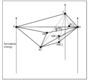
- the information processing system according to the fourth embodiment differs from the information processing system 100 according to the first embodiment in that the output unit 14 outputs third information indicating a phase diagram to which an energy axis has been added. Note that a description of the configuration common to the information processing system 100 according to the first embodiment will be omitted.
- Fig. 18 shows an example of a second image displayed on the display unit 3 in the fourth embodiment.
- Fig. 18 is an example of a second image including an enlarged image of a state diagram selected by a user. Note that in the example shown in Fig. 18, the execution icon "Save state diagram" is omitted.
- one or more energy axes are added to the phase diagram.
- Each energy axis represents the magnitude of the formation energy.
- the formation energies of elements A, B, and C are zero.
- the magnitude of energy represented by each energy axis is not limited to the magnitude of the formation energy, and may be other energy magnitudes.
- the phase diagram represented on the two-dimensional plane may be converted into a three-dimensional model and displayed on the display unit 3.
- the output unit 14 outputs the third information indicating the phase diagram, further including information indicating the energy of each substance (element or compound) included in the phase diagram. This enables the display control unit 30 to display on the display unit 3 a phase diagram to which one or more energy axes have been added.
- a phase diagram with one or more additional energy axes can be output. Therefore, in the fourth embodiment, it becomes easier to visually recognize the stability of compounds included in the phase diagram. For example, in the first embodiment, the user can understand whether or not a compound included in the phase diagram is thermodynamically stable, but it is difficult to understand how stable it is. In contrast, in the fourth embodiment, the user can easily visually understand how stable each compound is, or how unstable a target compound is, by looking at a phase diagram with one or more additional energy axes.
- the second image displayed on the display unit 3 may further include a multi-element state diagram in addition to a state diagram, as in the example shown in FIG. 3.
- the display control unit 30 may cause the display unit 3 to display a second image that further includes a multi-element state diagram.
- the planes cut out may be indicated by hatching, as in the example shown in FIG. 3.
- the display control unit 30 may cause the display unit 3 to display a second image in which a plane or line (hatched portion) representing at least one state diagram is superimposed on the multi-element state diagram.
- the first storage unit 4 and the second storage unit 5 are realized by different recording media, but this is not limited to this.
- the first storage unit 4 and the second storage unit 5 may be realized by the same recording medium.
- the first acquisition unit 11 and the second acquisition unit 12 are different acquisition units, but they may be realized by the same acquisition unit.
- the information processing system is configured with the first acquisition unit 11, the second acquisition unit 12, the generation unit 13, and the output unit 14, but is not limited to this.
- the information processing system may be configured with the display control unit 30 and the display unit 3, as shown by "100A" in FIG. 5.
- each component may be configured with dedicated hardware, or may be realized by executing a software program suitable for each component.
- Each component may be realized by a program execution unit such as a CPU (Central Processing Unit) or a processor reading and executing a software program recorded on a recording medium such as a hard disk or semiconductor memory.
- a program execution unit such as a CPU (Central Processing Unit) or a processor reading and executing a software program recorded on a recording medium such as a hard disk or semiconductor memory.
- the at least one device is a computer system consisting of a microprocessor, a ROM (Read Only Memory), a RAM (Random Access Memory), a hard disk unit, a display unit, a keyboard, or a mouse.
- a computer program is stored in the RAM or hard disk unit.
- the at least one device achieves its function by the microprocessor operating in accordance with the computer program.
- the computer program is composed of a combination of multiple instruction codes that indicate commands for a computer to achieve a specified function.
- a system LSI is an ultra-multifunctional LSI manufactured by integrating multiple components on a single chip, and specifically, is a computer system including a microprocessor, ROM, RAM, etc. A computer program is stored in the RAM. The system LSI achieves its functions when the microprocessor operates in accordance with the computer program.
- Some or all of the components constituting at least one of the above devices may be composed of an IC card or a standalone module that is detachable from the device.
- the IC card or module is a computer system composed of a microprocessor, ROM, RAM, etc.
- the IC card or module may include the above-mentioned ultra-multifunction LSI.
- the IC card or module achieves its functions by the microprocessor operating according to a computer program. This IC card or module may be tamper-resistant.
- the present disclosure may be the methods described above. It may also be a computer program that implements these methods using a computer, or a digital signal that comprises a computer program.
- the present disclosure may also be a computer program or digital signal recorded on a computer-readable recording medium, such as a flexible disk, a hard disk, a CD (Compact Disc)-ROM, a DVD, a DVD-ROM, a DVD-RAM, a BD (Blu-ray (registered trademark) Disc), or a semiconductor memory. It may also be a digital signal recorded on such a recording medium.
- a computer-readable recording medium such as a flexible disk, a hard disk, a CD (Compact Disc)-ROM, a DVD, a DVD-ROM, a DVD-RAM, a BD (Blu-ray (registered trademark) Disc), or a semiconductor memory. It may also be a digital signal recorded on such a recording medium.
- the present disclosure may also involve the transmission of computer programs or digital signals via telecommunications lines, wireless or wired communication lines, networks such as the Internet, or data broadcasting, etc.
- the program or digital signal may also be implemented by another independent computer system by recording it on a recording medium and transferring it, or by transferring the program or digital signal via a network, etc.
- the present disclosure has the effect of, for example, appropriately assisting a user in exploring the production process of inorganic materials, and can be used in a computer device or system for displaying information about the production process.
- Second storage unit 100 100, 200, 300 Information processing system 100A Information processing system
Landscapes
- Engineering & Computer Science (AREA)
- Chemical & Material Sciences (AREA)
- Bioinformatics & Cheminformatics (AREA)
- Computing Systems (AREA)
- Theoretical Computer Science (AREA)
- Life Sciences & Earth Sciences (AREA)
- Bioinformatics & Computational Biology (AREA)
- Crystallography & Structural Chemistry (AREA)
- Health & Medical Sciences (AREA)
- Data Mining & Analysis (AREA)
- General Health & Medical Sciences (AREA)
- Physics & Mathematics (AREA)
- Spectroscopy & Molecular Physics (AREA)
- Pharmacology & Pharmacy (AREA)
- Medicinal Chemistry (AREA)
- Computer Vision & Pattern Recognition (AREA)
- Software Systems (AREA)
- Medical Informatics (AREA)
- Evolutionary Computation (AREA)
- Databases & Information Systems (AREA)
- Artificial Intelligence (AREA)
- User Interface Of Digital Computer (AREA)
Priority Applications (3)
| Application Number | Priority Date | Filing Date | Title |
|---|---|---|---|
| CN202480030264.3A CN121127922A (zh) | 2023-06-01 | 2024-05-23 | 信息处理方法、信息处理系统和程序 |
| JP2025524040A JPWO2024247879A1 (https=) | 2023-06-01 | 2024-05-23 | |
| US19/389,522 US20260074024A1 (en) | 2023-06-01 | 2025-11-14 | Information processing method, information processing system, and program |
Applications Claiming Priority (2)
| Application Number | Priority Date | Filing Date | Title |
|---|---|---|---|
| JP2023091015 | 2023-06-01 | ||
| JP2023-091015 | 2023-06-01 |
Related Child Applications (1)
| Application Number | Title | Priority Date | Filing Date |
|---|---|---|---|
| US19/389,522 Continuation US20260074024A1 (en) | 2023-06-01 | 2025-11-14 | Information processing method, information processing system, and program |
Publications (1)
| Publication Number | Publication Date |
|---|---|
| WO2024247879A1 true WO2024247879A1 (ja) | 2024-12-05 |
Family
ID=93657919
Family Applications (1)
| Application Number | Title | Priority Date | Filing Date |
|---|---|---|---|
| PCT/JP2024/019018 Ceased WO2024247879A1 (ja) | 2023-06-01 | 2024-05-23 | 情報処理方法、情報処理システム、及びプログラム |
Country Status (4)
| Country | Link |
|---|---|
| US (1) | US20260074024A1 (https=) |
| JP (1) | JPWO2024247879A1 (https=) |
| CN (1) | CN121127922A (https=) |
| WO (1) | WO2024247879A1 (https=) |
Citations (2)
| Publication number | Priority date | Publication date | Assignee | Title |
|---|---|---|---|---|
| JP2019517979A (ja) * | 2016-05-05 | 2019-06-27 | ソリディア テクノロジーズ インコーポレイテッドSolidia Technologies, Inc. | 合成ポゾラン |
| WO2023008449A1 (ja) * | 2021-07-28 | 2023-02-02 | パナソニックIpマネジメント株式会社 | 情報表示方法、情報表示装置およびプログラム |
-
2024
- 2024-05-23 JP JP2025524040A patent/JPWO2024247879A1/ja active Pending
- 2024-05-23 CN CN202480030264.3A patent/CN121127922A/zh active Pending
- 2024-05-23 WO PCT/JP2024/019018 patent/WO2024247879A1/ja not_active Ceased
-
2025
- 2025-11-14 US US19/389,522 patent/US20260074024A1/en active Pending
Patent Citations (2)
| Publication number | Priority date | Publication date | Assignee | Title |
|---|---|---|---|---|
| JP2019517979A (ja) * | 2016-05-05 | 2019-06-27 | ソリディア テクノロジーズ インコーポレイテッドSolidia Technologies, Inc. | 合成ポゾラン |
| WO2023008449A1 (ja) * | 2021-07-28 | 2023-02-02 | パナソニックIpマネジメント株式会社 | 情報表示方法、情報表示装置およびプログラム |
Also Published As
| Publication number | Publication date |
|---|---|
| JPWO2024247879A1 (https=) | 2024-12-05 |
| US20260074024A1 (en) | 2026-03-12 |
| CN121127922A (zh) | 2025-12-12 |
Similar Documents
| Publication | Publication Date | Title |
|---|---|---|
| JP6043732B2 (ja) | 異種マップデータをブラウジングするためのシステムの方法およびシステム | |
| US9600149B2 (en) | Display processing system, display processing method, and information storage medium | |
| JP2004178604A5 (https=) | ||
| JP2009110360A (ja) | 画像処理装置及び画像処理方法 | |
| TW201428514A (zh) | 導航內容階層及持續內容項目集合 | |
| US20130174074A1 (en) | Method and device for arranging information that is linked in complex ways and for pathfinding in such information | |
| JP2026002901A (ja) | 情報処理装置、情報処理方法、及びプログラム | |
| US20160077691A1 (en) | Data processing apparatus, data processing method, and storage medium | |
| US11537643B2 (en) | Systems and methods for coordinate-based search | |
| Wen et al. | Bayesian optimization acquisition functions for accelerated search of cluster expansion convex hull of multi-component alloys | |
| US20250006314A1 (en) | Information processing method, information processing system, and recording medium | |
| Masselot et al. | Constrained groupwise additive index models | |
| Handy* et al. | Large vibrational variational calculations using ‘multimode’and an iterative diagonalization technique | |
| WO2024247879A1 (ja) | 情報処理方法、情報処理システム、及びプログラム | |
| CN104169918A (zh) | 信息管理设备、信息管理方法和程序 | |
| Leng et al. | Model selection in nonparametric hazard regression | |
| Dallago et al. | CellMap visualizes protein-protein interactions and subcellular localization | |
| WO2024247790A1 (ja) | 情報処理方法、情報処理システム、及びプログラム | |
| Inada et al. | Atomic descriptors generated from coordination polyhedra in crystal structures | |
| Rummel et al. | An autonomous petrological database for geodynamic simulations of magmatic systems | |
| EP4503044A1 (en) | Information processing method, information processing system, and program | |
| Praneenararat et al. | Interactive, multiscale navigation of large and complicated biological networks | |
| JP5634209B2 (ja) | 検索インデックス作成システム、文書検索システム、インデックス作成方法、文書検索方法及びプログラム | |
| JP7766469B2 (ja) | 分析装置、分析方法、及びプログラム | |
| JP7599641B1 (ja) | ネオアンチゲン予測装置、ネオアンチゲン予測方法、およびプログラム |
Legal Events
| Date | Code | Title | Description |
|---|---|---|---|
| 121 | Ep: the epo has been informed by wipo that ep was designated in this application |
Ref document number: 24815363 Country of ref document: EP Kind code of ref document: A1 |
|
| ENP | Entry into the national phase |
Ref document number: 2025524040 Country of ref document: JP Kind code of ref document: A |
|
| NENP | Non-entry into the national phase |
Ref country code: DE |