WO2024247795A1 - 蓄電素子用正極、蓄電素子及び蓄電装置 - Google Patents
蓄電素子用正極、蓄電素子及び蓄電装置 Download PDFInfo
- Publication number
- WO2024247795A1 WO2024247795A1 PCT/JP2024/018571 JP2024018571W WO2024247795A1 WO 2024247795 A1 WO2024247795 A1 WO 2024247795A1 JP 2024018571 W JP2024018571 W JP 2024018571W WO 2024247795 A1 WO2024247795 A1 WO 2024247795A1
- Authority
- WO
- WIPO (PCT)
- Prior art keywords
- positive electrode
- active material
- electrode active
- material layer
- storage element
- Prior art date
- Legal status (The legal status is an assumption and is not a legal conclusion. Google has not performed a legal analysis and makes no representation as to the accuracy of the status listed.)
- Ceased
Links
Images


Classifications
-
- H—ELECTRICITY
- H01—ELECTRIC ELEMENTS
- H01G—CAPACITORS; CAPACITORS, RECTIFIERS, DETECTORS, SWITCHING DEVICES, LIGHT-SENSITIVE OR TEMPERATURE-SENSITIVE DEVICES OF THE ELECTROLYTIC TYPE
- H01G11/00—Hybrid capacitors, i.e. capacitors having different positive and negative electrodes; Electric double-layer [EDL] capacitors; Processes for the manufacture thereof or of parts thereof
- H01G11/22—Electrodes
- H01G11/26—Electrodes characterised by their structure, e.g. multi-layered, porosity or surface features
-
- H—ELECTRICITY
- H01—ELECTRIC ELEMENTS
- H01G—CAPACITORS; CAPACITORS, RECTIFIERS, DETECTORS, SWITCHING DEVICES, LIGHT-SENSITIVE OR TEMPERATURE-SENSITIVE DEVICES OF THE ELECTROLYTIC TYPE
- H01G11/00—Hybrid capacitors, i.e. capacitors having different positive and negative electrodes; Electric double-layer [EDL] capacitors; Processes for the manufacture thereof or of parts thereof
- H01G11/04—Hybrid capacitors
- H01G11/06—Hybrid capacitors with one of the electrodes allowing ions to be reversibly doped thereinto, e.g. lithium ion capacitors [LIC]
-
- H—ELECTRICITY
- H01—ELECTRIC ELEMENTS
- H01G—CAPACITORS; CAPACITORS, RECTIFIERS, DETECTORS, SWITCHING DEVICES, LIGHT-SENSITIVE OR TEMPERATURE-SENSITIVE DEVICES OF THE ELECTROLYTIC TYPE
- H01G11/00—Hybrid capacitors, i.e. capacitors having different positive and negative electrodes; Electric double-layer [EDL] capacitors; Processes for the manufacture thereof or of parts thereof
- H01G11/22—Electrodes
- H01G11/26—Electrodes characterised by their structure, e.g. multi-layered, porosity or surface features
- H01G11/28—Electrodes characterised by their structure, e.g. multi-layered, porosity or surface features arranged or disposed on a current collector; Layers or phases between electrodes and current collectors, e.g. adhesives
-
- H—ELECTRICITY
- H01—ELECTRIC ELEMENTS
- H01G—CAPACITORS; CAPACITORS, RECTIFIERS, DETECTORS, SWITCHING DEVICES, LIGHT-SENSITIVE OR TEMPERATURE-SENSITIVE DEVICES OF THE ELECTROLYTIC TYPE
- H01G11/00—Hybrid capacitors, i.e. capacitors having different positive and negative electrodes; Electric double-layer [EDL] capacitors; Processes for the manufacture thereof or of parts thereof
- H01G11/22—Electrodes
- H01G11/30—Electrodes characterised by their material
- H01G11/46—Metal oxides
-
- H—ELECTRICITY
- H01—ELECTRIC ELEMENTS
- H01G—CAPACITORS; CAPACITORS, RECTIFIERS, DETECTORS, SWITCHING DEVICES, LIGHT-SENSITIVE OR TEMPERATURE-SENSITIVE DEVICES OF THE ELECTROLYTIC TYPE
- H01G11/00—Hybrid capacitors, i.e. capacitors having different positive and negative electrodes; Electric double-layer [EDL] capacitors; Processes for the manufacture thereof or of parts thereof
- H01G11/22—Electrodes
- H01G11/30—Electrodes characterised by their material
- H01G11/50—Electrodes characterised by their material specially adapted for lithium-ion capacitors, e.g. for lithium-doping or for intercalation
-
- H—ELECTRICITY
- H01—ELECTRIC ELEMENTS
- H01M—PROCESSES OR MEANS, e.g. BATTERIES, FOR THE DIRECT CONVERSION OF CHEMICAL ENERGY INTO ELECTRICAL ENERGY
- H01M4/00—Electrodes
- H01M4/02—Electrodes composed of, or comprising, active material
- H01M4/36—Selection of substances as active materials, active masses, active liquids
- H01M4/58—Selection of substances as active materials, active masses, active liquids of inorganic compounds other than oxides or hydroxides, e.g. sulfides, selenides, tellurides, halogenides or LiCoFy; of polyanionic structures, e.g. phosphates, silicates or borates
- H01M4/5825—Oxygenated metallic salts or polyanionic structures, e.g. borates, phosphates, silicates, olivines
-
- H—ELECTRICITY
- H01—ELECTRIC ELEMENTS
- H01M—PROCESSES OR MEANS, e.g. BATTERIES, FOR THE DIRECT CONVERSION OF CHEMICAL ENERGY INTO ELECTRICAL ENERGY
- H01M4/00—Electrodes
- H01M4/02—Electrodes composed of, or comprising, active material
- H01M4/64—Carriers or collectors
- H01M4/66—Selection of materials
- H01M4/661—Metal or alloys, e.g. alloy coatings
-
- H—ELECTRICITY
- H01—ELECTRIC ELEMENTS
- H01M—PROCESSES OR MEANS, e.g. BATTERIES, FOR THE DIRECT CONVERSION OF CHEMICAL ENERGY INTO ELECTRICAL ENERGY
- H01M50/00—Constructional details or processes of manufacture of the non-active parts of electrochemical cells other than fuel cells, e.g. hybrid cells
- H01M50/10—Primary casings; Jackets or wrappings
- H01M50/102—Primary casings; Jackets or wrappings characterised by their shape or physical structure
- H01M50/103—Primary casings; Jackets or wrappings characterised by their shape or physical structure prismatic or rectangular
-
- H—ELECTRICITY
- H01—ELECTRIC ELEMENTS
- H01M—PROCESSES OR MEANS, e.g. BATTERIES, FOR THE DIRECT CONVERSION OF CHEMICAL ENERGY INTO ELECTRICAL ENERGY
- H01M50/00—Constructional details or processes of manufacture of the non-active parts of electrochemical cells other than fuel cells, e.g. hybrid cells
- H01M50/50—Current conducting connections for cells or batteries
- H01M50/543—Terminals
- H01M50/547—Terminals characterised by the disposition of the terminals on the cells
- H01M50/55—Terminals characterised by the disposition of the terminals on the cells on the same side of the cell
-
- Y—GENERAL TAGGING OF NEW TECHNOLOGICAL DEVELOPMENTS; GENERAL TAGGING OF CROSS-SECTIONAL TECHNOLOGIES SPANNING OVER SEVERAL SECTIONS OF THE IPC; TECHNICAL SUBJECTS COVERED BY FORMER USPC CROSS-REFERENCE ART COLLECTIONS [XRACs] AND DIGESTS
- Y02—TECHNOLOGIES OR APPLICATIONS FOR MITIGATION OR ADAPTATION AGAINST CLIMATE CHANGE
- Y02E—REDUCTION OF GREENHOUSE GAS [GHG] EMISSIONS, RELATED TO ENERGY GENERATION, TRANSMISSION OR DISTRIBUTION
- Y02E60/00—Enabling technologies; Technologies with a potential or indirect contribution to GHG emissions mitigation
- Y02E60/10—Energy storage using batteries
Definitions
- the present invention relates to a positive electrode for an energy storage element, an energy storage element, and an energy storage device.
- Non-aqueous electrolyte secondary batteries such as lithium-ion non-aqueous electrolyte secondary batteries
- Non-aqueous electrolyte secondary batteries are widely used in electronic devices such as personal computers and communication terminals, as well as automobiles, due to their high energy density.
- Non-aqueous electrolyte secondary batteries generally comprise an electrode body having a pair of electrodes electrically isolated by a separator, and a non-aqueous electrolyte interposed between the electrodes, and are configured to charge and discharge by transferring charge-transporting ions between the two electrodes.
- capacitors such as lithium-ion capacitors and electric double-layer capacitors are also widely used as storage elements.
- the positive electrode of a storage element has a layer containing a positive electrode active material that can absorb and release charge-transporting ions.
- Patent Document 1 describes an invention for a positive electrode for a non-aqueous electrolyte secondary battery that has a structure in which a conductive base layer is provided between a positive electrode current collector sheet and a positive electrode active material layer.
- the present invention aims to provide a positive electrode for an electric storage element having a structure in which a positive electrode active material layer is directly laminated on a positive electrode substrate, with reduced electrical resistance, and an electric storage element and an electric storage device in which such a positive electrode for an electric storage element is used.
- the positive electrode for a storage element comprises a positive electrode substrate containing metallic aluminum and having a surface on which the metallic aluminum is exposed, and a positive electrode active material layer containing positive electrode active material particles, which is laminated directly on the surface on which the metallic aluminum is exposed, the breaking strength of the positive electrode active material particles being 30 MPa or more, the average particle size of the positive electrode active material particles being 3 ⁇ m or more, the positive electrode active material layer containing a non-aqueous binder, and the proportion of the area of the recesses in the region on the surface on which the metallic aluminum is exposed where the positive electrode active material layer is laminated being 5% or more.
- Another aspect of the present invention relates to an energy storage element that includes an electrode for the energy storage element.
- Another aspect of the present invention relates to a storage device that includes two or more storage elements and includes one or more of the storage elements.
- a positive electrode for an electric storage element having a structure in which a positive electrode active material layer is directly laminated on a positive electrode substrate, and in which electrical resistance is reduced, as well as an electric storage element and an electric storage device in which such a positive electrode for an electric storage element is used.
- FIG. 1 is a schematic cross-sectional view showing one embodiment of a positive electrode for an energy storage element.
- FIG. 2 is a perspective view showing one embodiment of an energy storage element.
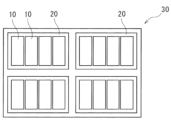
- FIG. 3 is a schematic diagram showing an embodiment of an electricity storage device configured by assembling a plurality of electricity storage elements.
- a positive electrode for a storage element comprises a positive electrode substrate containing metallic aluminum and having a surface on which the metallic aluminum is exposed, and a positive electrode active material layer containing positive electrode active material particles, which is laminated directly on the surface on which the metallic aluminum is exposed, the breaking strength of the positive electrode active material particles being 30 MPa or more, the average particle size of the positive electrode active material particles being 3 ⁇ m or more, the positive electrode active material layer containing a non-aqueous binder, and the proportion of the area of the recesses in the region on the surface on which the metallic aluminum is exposed where the positive electrode active material layer is laminated being 5% or more.
- the positive electrode for a storage element described in [1] above (hereinafter, simply referred to as "positive electrode”) is a positive electrode having a structure in which a positive electrode active material layer is directly laminated on a positive electrode substrate, and the electrical resistance is reduced.
- the reason for this is unclear, but the following reason is presumed.
- the positive electrode active material particles used in the positive electrode described in [1] above are hard with a breaking strength of 30 MPa or more, and have a sufficient average particle size of 3 ⁇ m or more.
- a positive electrode active material layer containing such positive electrode active material particles is laminated on a positive electrode substrate and pressed, so that at least a part of the positive electrode active material particles is embedded in the positive electrode substrate.
- the proportion of the area of the recess in the region where the positive electrode active material layer is laminated on the surface where the metal aluminum is exposed represents the degree to which the positive electrode active material particles are embedded in the positive electrode substrate.
- a proportion of the area of the recess of 5% or more represents a large number of positive electrode active material particles that are sufficiently embedded in the positive electrode substrate.
- the breaking strength of the positive electrode active material particles is less than 30 MPa, and when the average particle size of the positive electrode active material particles is less than 3 ⁇ m, the positive electrode active material particles do not sufficiently embed into the positive electrode substrate even when pressed during the manufacturing process of the positive electrode, so the effect of reducing electrical resistance is not achieved.
- the non-aqueous binder is softer than the aqueous binder, the positive electrode active material particles do not embed too much into the positive electrode substrate, and the strength of the positive electrode substrate can be maintained.
- the breaking strength and average particle size of the positive electrode active material particles are measured on the positive electrode in a fully discharged state by the following method.
- the storage element is charged at a constant current of 0.1 C until the charging end voltage during normal use is reached, and the storage element is fully charged.
- the storage element is discharged at a constant current of 0.1 C until the discharging end voltage during normal use (lower limit voltage).
- the storage element is disassembled, the positive electrode is removed, and a test battery is assembled with a metallic lithium electrode as the counter electrode.
- constant current discharge is performed until the positive electrode potential becomes 2.0 V vs.
- the positive electrode is adjusted to a fully discharged state.
- the test battery is disassembled again, and the positive electrode is removed.
- the electrolyte attached to the removed positive electrode is thoroughly washed using dimethyl carbonate, and the positive electrode active material particles are collected after drying at room temperature for one day and night.
- the collected positive electrode active material particles are subjected to measurement.
- the operations from dismantling the storage element to collecting the positive electrode active material particles are carried out in an argon atmosphere with a dew point of -60°C or less.
- "During normal use” refers to a case where the storage element is used under the charging and discharging conditions recommended or specified for the storage element.
- the charging conditions for example, if a charger for the storage element is prepared, the storage element may be used using the charger.
- the "breaking strength" of the positive electrode active material particles is measured by a micro-compression test using a micro-compression tester (Shimadzu Corporation's "MCT-511"). Specifically, in compression test mode, the breaking test force is measured under the following conditions: indenter type: FLAT50, load speed: 0.1340 mN/sec, test force: 1.0 mN to 30.0 mN, and the breaking strength of the positive electrode active material is calculated in accordance with JIS-R-1639-5 (2007). The breaking strength is measured for five positive electrode active material particles, and the average value is used.
- the "average particle size" of the positive electrode active material particles is the value at which the volume-based cumulative distribution calculated in accordance with JIS-Z-8819-2 (2001) is 50%, based on the particle size distribution measured by the laser diffraction/scattering method for a solution in which the particles are diluted with a solvent, in accordance with JIS-Z-8825 (2013). The same applies to the average particle size of other particles.
- the "recess" in the positive electrode substrate refers to a recess having a diameter of 1 ⁇ m or more.
- the "area ratio of the recess in the region where the positive electrode active material layer is laminated on the surface where the metal aluminum is exposed” is obtained by immersing the positive electrode in a solvent capable of dissolving the non-aqueous binder contained in the positive electrode, performing ultrasonic cleaning at a temperature of 80° C. to peel off the positive electrode active material layer from the positive electrode, and observing the obtained positive electrode substrate with a scanning electron microscope (SEM).
- SEM scanning electron microscope
- a JSM-7001F manufactured by JEOL Ltd.
- the SEM image is a secondary electron image observed.
- the acceleration voltage is 15 kV.
- the observation magnification is set to 20,000 times. Other conditions such as spot diameter, working distance, irradiation current, brightness, and focus are appropriately set so that the contour of the recess is clear.
- the surface of the positive electrode substrate in the region where the positive electrode active material layer was laminated on the surface where the metal aluminum is exposed is observed with an SEM, and the obtained SEM image is saved as an image file.
- image analysis software the area of each recess having a diameter of 1 ⁇ m or more in an observation area range of 2.88 mm2 is added up, and the ratio of the total area of the recesses to the area (2.88 mm2 ) of the region where the positive electrode active material layer was laminated on the surface where the metallic aluminum was exposed is calculated.
- the longest diameter is taken as the diameter.
- the "ratio of the area of the recesses in the region where the positive electrode active material layer is not laminated (on the surface where the metallic aluminum is exposed)" described later is also measured and calculated in the same manner.
- a positive electrode using a surface-roughened positive electrode substrate also has a large contact area between the positive electrode substrate and the positive electrode active material particles, so that the electrical resistance is reduced.
- a surface-roughened positive electrode substrate is expensive.
- a surface-roughened positive electrode substrate may have a reduced strength due to the positive electrode active material particles being embedded in it, which may cause problems in terms of production. In the case of a surface-roughened positive electrode substrate, the entire surface is generally uniformly roughened.
- the ratio of the area of the recesses in the region where the positive electrode active material layer is not laminated exceeds 0.5%, it is generally assumed that a surface-roughened positive electrode substrate is used.
- the ratio of the area of the recesses in the region where the positive electrode active material layer is not laminated is 0.5% or less, that is, a surface-roughened positive electrode substrate is used, so that it is possible to reduce costs and improve strength.
- the positive electrode active material particles may contain a lithium transition metal compound having a polyanion structure.
- Lithium transition metal compounds having a polyanion structure usually have lower electronic conductivity than other positive electrode active materials. For this reason, in the case of the positive electrode described in [3] above, in which the positive electrode active material particles contain a lithium transition metal compound having a polyanion structure, the advantage of reduced electrical resistance is great.
- the positive electrode active material layer may have a density of 1.5 g/ cm3 or more.
- the positive electrode described in [4] above has a further reduced electrical resistance.
- the “density” of the positive electrode active material layer is a value calculated from the mass per area of the positive electrode active material layer and the average thickness of one layer of the positive electrode active material layer. In other words, the “density" of the positive electrode active material layer is the apparent density. In the case where positive electrode active material layers are provided on both sides of the positive electrode substrate, it is the average thickness of one positive electrode active material layer provided on one side of the positive electrode substrate. The average thickness of the positive electrode active material layer is the average value of thicknesses measured at any five points.
- the positive electrode active material layer may further contain a conductive agent, and the content of the conductive agent in the positive electrode active material layer may be 0.5 mass% or more.
- the positive electrode described in [5] above has a further reduced electrical resistance.
- Another aspect of the present invention relates to a storage element having a positive electrode described in any one of [1] to [5] above.
- the storage element described in [6] above has a positive electrode described in any one of [1] to [5] above, and therefore has reduced electrical resistance.
- Another aspect of the present invention relates to an energy storage device that includes two or more energy storage elements, and includes one or more energy storage elements described in [6] above.
- the storage device described in [7] above has one or more storage elements described in [6] above, and therefore has reduced electrical resistance.
- a positive electrode, a manufacturing method for a positive electrode, an energy storage element, an energy storage device, a manufacturing method for an energy storage element, and other embodiments according to one embodiment of the present invention will be described in detail. Note that the names of the components (elementary components) used in each embodiment may differ from the names of the components (elementary components) used in the background art.
- ⁇ Positive electrode> 1 includes a positive electrode substrate 2 and a positive electrode active material layer 3 laminated directly on the positive electrode substrate 2.
- the positive electrode 1 is a positive electrode for an electricity storage element, and is preferably a positive electrode for a non-aqueous electrolyte electricity storage element.
- the positive electrode substrate 2 has electrical conductivity. Whether or not it has "electrical conductivity" is determined by using a volume resistivity measured in accordance with JIS-H-0505 (1975) of 10 -2 ⁇ cm as a threshold value.
- the positive electrode substrate 2 contains metallic aluminum.
- Metallic aluminum is a substance that contains aluminum element and has metallic properties.
- Metallic aluminum may be pure aluminum or an aluminum alloy.
- the positive electrode substrate 2 may be substantially made of pure aluminum or an aluminum alloy, or may be made of pure aluminum or an aluminum alloy.
- the content of aluminum element in the positive electrode substrate 2 may be 80 mass% or more and 100 mass% or less, or 95 mass% or more and 100 mass% or less. Examples of pure aluminum or aluminum alloys include A1085, A3003, A1N30, etc., as specified in JIS-H-4000 (2014) or JIS-H-4160 (2006).
- the positive electrode substrate 2 shown in FIG. 1 has a plate shape.
- the positive electrode substrate 2 may be, for example, a substrate made of a material other than metallic aluminum on which a metallic aluminum layer is provided by vapor deposition or the like, but is preferably a metallic aluminum foil. That is, the positive electrode substrate 2 is preferably a pure aluminum foil or an aluminum alloy foil. In the following, pure aluminum foil and aluminum alloy foil are collectively referred to as aluminum foil.
- the positive electrode substrate 2 has a surface on which metallic aluminum is exposed.
- the positive electrode substrate 2 may have metallic aluminum exposed over the entire surface.
- metallic aluminum is usually exposed over the entire surface of the positive electrode substrate 2.
- the average thickness of the positive electrode substrate 2 is preferably 3 ⁇ m or more and 50 ⁇ m or less, more preferably 5 ⁇ m or more and 40 ⁇ m or less, even more preferably 8 ⁇ m or more and 30 ⁇ m or less, and particularly preferably 10 ⁇ m or more and 25 ⁇ m or less.
- the positive electrode active material layer 3 is directly laminated on the surface where the metallic aluminum of the positive electrode substrate 2 is exposed.
- the positive electrode active material layer 3 is laminated on both sides of the positive electrode substrate 2 (the upper and lower surfaces of the positive electrode substrate 2 in FIG. 1).
- the positive electrode active material layer 3 is not laminated on the entire surface of both sides of the positive electrode substrate 2. That is, on the surface where the metallic aluminum of the positive electrode substrate 2 is exposed (the upper and lower surfaces of the positive electrode substrate 2 in FIG. 1), there are an area 4 where the positive electrode active material layer 3 is laminated and an area 5 where the positive electrode active material layer 3 is not laminated.
- upper surface and lower surface merely represent the two main surfaces of the plate-shaped positive electrode substrate 2, respectively, and do not limit the orientation, etc., of the positive electrode 1 when it is used.
- the area 5 where the positive electrode active material layer 3 is not laminated is the part that connects to the positive electrode lead 14 in the energy storage element 10 of FIG. 2 described later.
- a recess 6 is formed in the region 4 where the positive electrode active material layer 3 is laminated on the surface where the metallic aluminum of the positive electrode substrate 2 is exposed.
- the recess 6 is formed by the positive electrode active material particles (not shown) contained in the positive electrode active material layer 3, which will be described later, being embedded in the positive electrode substrate 2.
- the lower limit of the area ratio of the recess 6 in the region 4 where the positive electrode active material layer 3 is laminated is 5%, preferably 8%, more preferably 10%, and in some cases even more preferably 12%, 15%, or 20%.
- the area ratio of the recess 6 in the region 4 where the positive electrode active material layer 3 is laminated is equal to or greater than the above lower limit, the contact area between the positive electrode active material particles and the positive electrode substrate 2 is increased, and the electrical resistance is reduced.
- the upper limit of the area ratio of the recess 6 in the region 4 where the positive electrode active material layer 3 is laminated may be, for example, 60%, 50%, or 40%.
- the area ratio of the recess 6 in the region 4 where the positive electrode active material layer 3 is laminated may be equal to or greater than any of the above lower limits and equal to or less than any of the above upper limits.
- the upper limit of the area ratio of the recesses 6 in the region 5 where the positive electrode active material layer 3 is not laminated on the surface where the metal aluminum is exposed in the positive electrode substrate 2 is preferably 0.5%, more preferably 0.1%.
- the lower limit of the area ratio of the recesses 6 in the region 5 where the positive electrode active material layer 3 is not laminated may be 0% or may be 0.01%. In this way, it is preferable that the recesses 6 are not substantially formed in the region 5 where the positive electrode active material layer 3 is not laminated.
- a positive electrode substrate 2 in which the recesses 6 are not substantially formed in the region 5 where the positive electrode active material layer 3 is not laminated typically a positive electrode substrate 2 that has not been roughened, can be used, and even when such a positive electrode substrate 2 is used, the electrical resistance is reduced.
- the area ratio of the recesses 6 in the region 5 where the positive electrode active material layer 3 is not laminated can be equal to or greater than any of the lower limits described above and equal to or less than any of the upper limits described above.
- the positive electrode active material layer 3 contains positive electrode active material particles and a non-aqueous binder.
- the positive electrode active material layer 3 contains optional components such as a conductive agent, a thickener, and a filler as necessary.
- the positive electrode active material particles are particles of a positive electrode active material.
- the positive electrode active material can be appropriately selected from known positive electrode active materials.
- As the positive electrode active material for a lithium ion secondary battery a material capable of absorbing and releasing lithium ions is usually used.
- As the positive electrode active material for example, a lithium transition metal composite oxide having an ⁇ -NaFeO 2 type crystal structure, a lithium transition metal composite oxide having a spinel type crystal structure, a lithium transition metal compound having a polyanion structure (hereinafter also referred to as a "polyanion compound”), a chalcogen compound, sulfur, etc. can be mentioned.
- lithium transition metal composite oxides having ⁇ -NaFeO 2 type crystal structure examples include Li[Li x Ni (1-x) ]O 2 (0 ⁇ x ⁇ 0.5), Li[Li x Ni ⁇ Co (1-x- ⁇ ) ]O 2 (0 ⁇ x ⁇ 0.5, 0 ⁇ 1, 0 ⁇ 1-x- ⁇ ), Li[Li x Co (1-x) ]O 2 (0 ⁇ x ⁇ 0.5), Li[Li x Ni ⁇ Mn (1-x- ⁇ ) ]O 2 (0 ⁇ x ⁇ 0.5, 0 ⁇ 1, 0 ⁇ 1-x- ⁇ ), Li[Li x Ni ⁇ Mn ⁇ Co (1-x- ⁇ - ⁇ ) ]O 2 (0 ⁇ x ⁇ 0.5, 0 ⁇ , 0 ⁇ , 0.5 ⁇ + ⁇ 1, 0 ⁇ 1-x- ⁇ - ⁇ ), Li[Li x Ni ⁇ Co ⁇ Al (1-x- ⁇ - ⁇ ) ]O 2 (0 ⁇ x ⁇ 0.5, 0 ⁇ , 0 ⁇ , 0.5 ⁇ + ⁇ 1, 0 ⁇ 1-x- ⁇ - ⁇
- lithium transition metal composite oxides having a spinel crystal structure examples include Li x Mn 2 O 4 and Li x Ni ⁇ Mn (2- ⁇ ) O 4 , etc.
- chalcogen compounds include titanium disulfide, molybdenum disulfide, molybdenum dioxide, etc.
- the polyanion compound will be described in detail later.
- the atoms or polyanions in these materials may be partially substituted with atoms or anion species consisting of other elements.
- the surfaces of these materials may be coated with other materials. In the positive electrode active material layer 3, one of these materials may be used alone, or two or more of them may be used in combination.
- the positive electrode active material particles preferably contain a polyanion compound.
- the polyanion compound include compounds containing an oxo acid anion (PO 4 3- , SO 4 2- , SiO 4 4- , BO 3 3- , VO 4 3- , etc.), a lithium ion, and a transition metal ion.
- the oxo acid anion may be a condensed anion (P 2 O 7 4- , P 3 O 10 5- , etc.).
- the polyanion compound may have an olivine crystal structure.
- the polyanion compound is typically a polyanion compound containing a lithium element and a transition metal element, and may further contain other elements (e.g., halogen elements, etc.).
- the transition metal element contained in the polyanion compound is preferably an iron element, a manganese element, a nickel element, or a cobalt element, and more preferably an iron element.
- the oxoacid anion contained in the polyanion compound is preferably a phosphate anion (PO 4 3 ⁇ ).
- the polyanion compound is preferably a compound represented by the following formula (1).
- M is at least one transition metal element.
- A is at least one selected from B, Al, Si, P, S, Cl, Ti, V, Cr, Mo, and W.
- X is at least one halogen element.
- a, b, c, d, and e are numbers that satisfy 0 ⁇ a ⁇ 3, 0 ⁇ b ⁇ 2, 2 ⁇ c ⁇ 4, 1 ⁇ d ⁇ 3, and 0 ⁇ e ⁇ 1.
- a, b, c, d, and e may each be an integer or a decimal.
- M is preferably any one of Fe, Mn, Ni, and Co, or a combination of two or more of these.
- M is more preferably Fe, Mn, or a combination of these, and more preferably Fe.
- the content of Fe in M is preferably 50 mol% or more, and more preferably 70 mol% or more, 90 mol% or more, or 99 mol% or more.
- A is preferably P.
- polyanion compounds include LiFePO4 , LiCoPO4 , LiFe0.5Co0.5PO4 , LiMnPO4 , LiNiPO4 , LiMn0.5Fe0.5PO4 , LiCrPO4 , LiFeVO4 , Li2FeSiO4 , Li2Fe2( SO4 ) 3 , LiFeBO3 , LiFePO3.9F0.2 , Li3V2 ( PO4 ) 3 , Li2MnSiO4 , Li2CoPO4F , and the like . Atoms or polyanions in these polyanion compounds may be partially substituted with other atoms or anion species.
- the polyanion compounds may be used alone or in combination of two or more kinds.
- the lower limit of the content of the polyanion compound in the positive electrode active material particles may be 60 mass%, or may be 80 mass%, 90 mass%, 95 mass%, or 99 mass%.
- the upper limit of the content of the polyanion compound in the positive electrode active material particles may be 100 mass%, or may be 99.9 mass%.
- the positive electrode active material particles containing a polyanion compound may have at least a part of their surface coated with a carbon material.
- the carbon material is, for example, a material having a carbon element content of 80% by mass or more and 100% by mass or less.
- the carbon element content in the carbon material may be 90% by mass or more, or may be 95% by mass.
- elements other than the carbon element that may be contained in the carbon material include oxygen element, hydrogen element, and nitrogen element.
- Examples of the carbon material include graphite and non-graphitic carbon.
- the carbon material content in the positive electrode active material particles may be, for example, 0.1% by mass or more and 20% by mass or less, 0.2% by mass or more and 10% by mass or less, or 0.3% by mass or more and 5% by mass or less.
- the positive electrode active material particles may be multiple primary particles that do not aggregate but exist independently (single particles), but are preferably secondary particles formed by aggregation of multiple primary particles. Secondary particles of a polyanion compound are preferably used as the positive electrode active material particles.
- the lower limit of the breaking strength of the positive electrode active material particles is 30 MPa, preferably 40 MPa, and more preferably 50 MPa.
- the breaking strength of the positive electrode active material particles is equal to or greater than the lower limit, the positive electrode active material particles can be sufficiently embedded into the positive electrode substrate 2 by pressing or the like during the manufacturing process of the positive electrode, thereby reducing the electrical resistance. If the breaking strength of the positive electrode active material particles does not meet the lower limit, the positive electrode active material particles are likely to crack or deform during pressing or the like, and the positive electrode active material particles do not sufficiently embed into the positive electrode substrate 2, and the electrical resistance is not sufficiently reduced.
- the upper limit of the breaking strength of the positive electrode active material particles may be, for example, 200 MPa, or may be 150 MPa, 100 MPa, or 80 MPa.
- the breaking strength of the positive electrode active material particles may be equal to or greater than any of the lower limits described above and equal to or less than any of the upper limits described above.
- the breaking strength of the positive electrode active material particles can be controlled by the types of positive electrode active material and the carbon material that coats the surface, as well as by manufacturing conditions such as the method of making the positive electrode active material (hydrothermal method, solid phase method, etc.), the firing conditions, and the conditions of the method of forming the positive electrode active material particles (spray drying method, etc.).
- Positive electrode active material particles having a breaking strength within the above range can be selected and used from among commercially available known positive electrode active material particles by measuring the breaking strength.
- the lower limit of the average particle size of the positive electrode active material particles is 3 ⁇ m, preferably 4 ⁇ m, and more preferably 5 ⁇ m.
- the average particle size of the positive electrode active material particles is equal to or greater than the lower limit, the positive electrode active material particles are sufficiently embedded in the positive electrode substrate 2 by pressing or the like during the manufacturing process of the positive electrode, and the electrical resistance can be reduced.
- the upper limit of the average particle size of the positive electrode active material particles is preferably 30 ⁇ m, more preferably 20 ⁇ m, even more preferably 15 ⁇ m, and even more preferably 10 ⁇ m.
- the average particle size of the positive electrode active material particles is equal to or less than the upper limit, the pressing property is improved and a high-density positive electrode active material layer 3 can be formed, so that the energy density per volume of the positive electrode 1 and the storage element including this positive electrode 1 can be increased.
- the average particle size of the positive electrode active material particles is equal to or less than the upper limit, the number of contact points between the positive electrode active material particles and between the positive electrode active material and the positive electrode substrate 2 is increased, and the electrical resistance can be further reduced.
- the average particle size of the positive electrode active material particles can be equal to or greater than any of the lower limits and equal to or less than any of the upper limits.
- a pulverizer, a classifier, or the like is used.
- the pulverization method include a method using a mortar, a ball mill, a sand mill, a vibration ball mill, a planetary ball mill, a jet mill, a counter jet mill, a swirling airflow type jet mill, or a sieve.
- wet pulverization in the presence of water or an organic solvent such as hexane can also be used.
- a sieve or an air classifier can be used as necessary for both the dry and wet methods.
- the content of the positive electrode active material particles in the positive electrode active material layer 3 is preferably 70% by mass or more and 99% by mass or less, more preferably 80% by mass or more and 98% by mass or less, even more preferably 85% by mass or more and 97% by mass or less, and even more preferably 90% by mass or more and 95% by mass or less.
- non-aqueous binder refers to a binder that can be dissolved or dispersed in a non-aqueous solvent when preparing the positive electrode mixture paste.
- non-aqueous binders include polyvinylidene fluoride (PVDF), copolymers of vinylidene fluoride and hexafluoropropylene, copolymers of ethylene and vinyl alcohol, polyacrylonitrile, polyphosphazene, polysiloxane, polyvinyl acetate, polymethyl methacrylate, polystyrene, polycarbonate, polyamide, polyimide, polyamideimide, crosslinked polymers of cellulose and chitosan pyrrolidone carboxylate, and derivatives of chitin or chitosan.
- non-aqueous solvents include N-methylpyrrolidone (NMP).
- the content of the non-aqueous binder in the positive electrode active material layer 3 is preferably 1% by mass or more and 10% by mass or less, and more preferably 3% by mass or more and 6% by mass or less. By setting the content of the non-aqueous binder within the above range, the positive electrode active material particles can be stably held.
- the conductive agent is not particularly limited as long as it is a material having electrical conductivity.
- Examples of such conductive agents include carbon materials, metals, conductive ceramics, etc.
- Examples of carbon materials include graphite, non-graphitic carbon, graphene-based carbon, etc.
- Examples of non-graphitic carbon include carbon nanofibers, pitch-based carbon fibers, carbon black, etc.
- Examples of carbon black include furnace black, acetylene black, ketjen black, etc.
- Examples of graphene-based carbon include graphene, carbon nanotubes (CNT), fullerene, etc.
- Examples of the conductive agent include powder and fiber.
- the conductive agent one of these materials may be used alone, or two or more types may be mixed and used. These materials may also be used in combination.
- a material in which carbon black and CNT are combined may be used.
- carbon black is preferred from the viewpoints of electronic conductivity and coatability, and acetylene black is particularly preferred.
- the lower limit of the conductive agent content in the positive electrode active material layer 3 is preferably 0.5 mass%, more preferably 1 mass%, even more preferably 2 mass%, even more preferably 3 mass%, and even more preferably 4 mass%.
- the conductive agent content in the positive electrode active material layer 3 is equal to or greater than the above lower limit, the electrical resistance of the positive electrode 1 is further reduced.
- the upper limit of the conductive agent content in the positive electrode active material layer 3 is preferably 10 mass%, more preferably 9 mass%, even more preferably 8 mass%, and even more preferably 7 mass%, 6 mass%, or 5 mass%.
- the conductive agent content in the positive electrode active material layer 3 is equal to or less than the above upper limit, the content of the positive electrode active material particles can be increased, and the energy density of the storage element can be increased.
- the conductive agent content in the positive electrode active material layer 3 can be equal to or greater than any of the above lower limits and equal to or less than any of the above upper limits.
- the positive electrode active material layer 3 contains positive electrode active material particles whose surfaces are at least partially covered with a carbon material, the carbon material that covers the positive electrode active material particles is not included in the conductive agent.
- the thickener is not particularly limited, and any thickener that has the function of adjusting the viscosity of the positive electrode mixture paste containing positive electrode active material particles and a non-aqueous binder to a level suitable for coating can be used.
- the content of the thickener in the positive electrode active material layer 3 can be, for example, 0.1% by mass or more and 8% by mass or less, and can also be 5% by mass or less or 1% by mass or less.
- the technology disclosed herein can be preferably implemented in an embodiment in which the positive electrode active material layer 3 does not contain a thickener.
- the filler is not particularly limited.
- the filler include polyolefins such as polypropylene and polyethylene, inorganic oxides such as silicon dioxide, alumina, titanium dioxide, calcium oxide, strontium oxide, barium oxide, magnesium oxide, and aluminosilicate, hydroxides such as magnesium hydroxide, calcium hydroxide, and aluminum hydroxide, carbonates such as calcium carbonate, poorly soluble ion crystals such as calcium fluoride, barium fluoride, and barium sulfate, nitrides such as aluminum nitride and silicon nitride, mineral resource-derived substances such as talc, montmorillonite, boehmite, zeolite, apatite, kaolin, mullite, spinel, olivine, sericite, bentonite, and mica, and artificial products thereof.
- polyolefins such as polypropylene and polyethylene
- inorganic oxides such as silicon dioxide, alumina, titanium dioxide, calcium
- the content of the filler in the positive electrode active material layer 3 can be, for example, 0.1% by mass or more and 8% by mass or less, and can also be 5% by mass or less or 1% by mass or less.
- the technology disclosed herein can be preferably implemented in an embodiment in which the positive electrode active material layer 3 does not contain a filler.
- the positive electrode active material layer 3 may contain typical nonmetallic elements such as B, N, P, F, Cl, Br, and I, typical metallic elements such as Li, Na, Mg, Al, K, Ca, Zn, Ga, Ge, Sn, Sr, and Ba, and transition metallic elements such as Sc, Ti, V, Cr, Mn, Fe, Co, Ni, Cu, Mo, Zr, Nb, and W, as components other than the positive electrode active material particles, conductive agent, non-aqueous binder, thickener, and filler.
- typical nonmetallic elements such as B, N, P, F, Cl, Br, and I
- typical metallic elements such as Li, Na, Mg, Al, K, Ca, Zn, Ga, Ge, Sn, Sr, and Ba
- transition metallic elements such as Sc, Ti, V, Cr, Mn, Fe, Co, Ni, Cu, Mo, Zr, Nb, and W, as components other than the positive electrode active material particles, conductive agent, non-aqueous binder, thickener,
- the lower limit of the density of the positive electrode active material layer 3 is preferably 1.5 g/cm 3 , more preferably 1.6 g/cm 3 , even more preferably 1.7 g/cm 3 , and even more preferably 1.8 g/cm 3 , 1.9 g/cm 3 , 2.0 g/cm 3 , or 2.1 g/cm 3.
- the density of the positive electrode active material layer 3 is equal to or higher than the lower limit, the electrical resistance can be further reduced, and the discharge capacity per volume of the positive electrode active material layer 3 can be increased.
- the upper limit of the density of the positive electrode active material layer 3 is preferably 2.6 g/cm 3 , and more preferably 2.5 g/cm 3 , 2.4 g/cm 3 , or 2.3 g/cm 3.
- the density of the positive electrode active material layer 3 can be equal to or higher than any of the above-mentioned lower limits and equal to or lower than any of the above-mentioned upper limits.
- the density of the positive electrode active material layer 3 can be adjusted by the average particle size of the positive electrode active material particles, the strength of the press in the manufacturing process of the positive electrode, and the like.
- the mass per area of one layer of the positive electrode active material layer 3 is preferably 0.5 mg/100 cm 2 or more and 3.0 mg/100 cm 2 or less, and more preferably 0.7 mg/100 cm 2 or more and 2.0 mg/100 cm 2 or less. When the mass per area of one layer of the positive electrode active material layer 3 is within the above range, the discharge capacity of the storage element can be increased.
- the mass per area of one layer of the positive electrode active material layer 3 refers to the mass per area of one positive electrode active material layer 3 provided on one side of the positive electrode substrate 2 when the positive electrode active material layers 3 are provided on both sides of the positive electrode substrate 2 as in the positive electrode 1 of FIG. 1.
- the positive electrode can be manufactured, for example, by applying a positive electrode mixture paste to a positive electrode substrate having a surface on which metallic aluminum is exposed, drying the paste, laminating the positive electrode active material layer on the positive electrode substrate, and pressing the positive electrode mixture paste.
- the positive electrode mixture paste contains, for example, each component constituting the positive electrode active material layer and a dispersion medium. By pressing, at least a part of the positive electrode active material particles in the positive electrode active material layer is embedded in the positive electrode substrate, and a recess is formed on the surface (surface on which metallic aluminum is exposed) of the positive electrode substrate.
- the proportion of the area of the recess in the region where the positive electrode active material layer is laminated on the surface of the positive electrode substrate can be adjusted by the type, average thickness, type, breaking strength, average particle size, pressing strength, etc. of the positive electrode substrate.
- the electric storage element includes an electrode assembly having a positive electrode, a negative electrode, and a separator, an electrolyte, and a container for accommodating the electrode assembly and the electrolyte.
- the electrode assembly is usually a laminated type in which a plurality of positive electrodes and a plurality of negative electrodes are laminated with a separator interposed therebetween, or a wound type in which a positive electrode and a negative electrode are laminated with a separator interposed therebetween and wound.
- the electrolyte is present in a state contained in the positive electrode, the negative electrode, and the separator.
- the electrolyte may be a non-aqueous electrolyte.
- a non-aqueous electrolyte secondary battery hereinafter, also simply referred to as a "secondary battery" in which the electrolyte is a non-aqueous electrolyte will be described.
- the positive electrode provided in the electricity storage element can be the same as that described above as the positive electrode (positive electrode for electricity storage element) according to one embodiment of the present invention.
- the negative electrode has a negative electrode substrate and a negative electrode active material layer disposed on the negative electrode substrate directly or via an intermediate layer.
- the negative electrode substrate is conductive. Metals such as copper, nickel, stainless steel, nickel-plated steel, and aluminum, or alloys of these, and carbon materials are used as the material for the negative electrode substrate. Among these, copper or copper alloys are preferred. Examples of the negative electrode substrate include foil, vapor deposition film, mesh, and porous materials, with foil being preferred from the viewpoint of cost. Therefore, copper foil or copper alloy foil is preferred as the negative electrode substrate. Examples of copper foil include rolled copper foil and electrolytic copper foil.
- the average thickness of the negative electrode substrate is preferably 2 ⁇ m or more and 35 ⁇ m or less, more preferably 3 ⁇ m or more and 30 ⁇ m or less, even more preferably 4 ⁇ m or more and 25 ⁇ m or less, and particularly preferably 5 ⁇ m or more and 20 ⁇ m or less.
- the intermediate layer is a layer disposed between the negative electrode substrate and the negative electrode active material layer.
- the intermediate layer contains a conductive agent such as carbon particles to reduce the contact resistance between the negative electrode substrate and the negative electrode active material layer.
- the composition of the intermediate layer is not particularly limited, and may contain, for example, a binder and a conductive agent.
- the negative electrode active material layer contains a negative electrode active material.
- the negative electrode active material layer contains optional components such as a conductive agent, a binder, a thickener, and a filler as necessary.
- the optional components such as the conductive agent and the filler can be selected from the materials exemplified for the positive electrode above.
- the negative electrode active material layer may contain typical nonmetallic elements such as B, N, P, F, Cl, Br, and I, typical metallic elements such as Li, Na, Mg, Al, K, Ca, Zn, Ga, Ge, Sn, Sr, and Ba, and transition metallic elements such as Sc, Ti, V, Cr, Mn, Fe, Co, Ni, Cu, Mo, Zr, Ta, Hf, Nb, and W as components other than the negative electrode active material, conductive agent, binder, thickener, and filler.
- typical nonmetallic elements such as B, N, P, F, Cl, Br, and I
- typical metallic elements such as Li, Na, Mg, Al, K, Ca, Zn, Ga, Ge, Sn, Sr, and Ba
- transition metallic elements such as Sc, Ti, V, Cr, Mn, Fe, Co, Ni, Cu, Mo, Zr, Ta, Hf, Nb, and W as components other than the negative electrode active material, conductive agent, binder, thickener, and filler.
- the negative electrode active material can be appropriately selected from known negative electrode active materials.
- the negative electrode active material for lithium ion secondary batteries a material capable of absorbing and releasing lithium ions is usually used.
- the negative electrode active material include metal Li; metals or semimetals such as Si and Sn; metal oxides or semimetal oxides such as Si oxide, Ti oxide, and Sn oxide; titanium-containing oxides such as Li 4 Ti 5 O 12 , LiTiO 2, and TiNb 2 O 7 ; polyphosphate compounds; silicon carbide; carbon materials such as graphite and non-graphitic carbon (easily graphitized carbon or non-graphitizable carbon). Among these materials, graphite and non-graphitic carbon are preferred. In the negative electrode active material layer, one of these materials may be used alone, or two or more may be mixed and used.
- Graphite refers to a carbon material having an average lattice spacing (d 002 ) of the (002) plane determined by X-ray diffraction before charging and discharging or in a discharged state of 0.33 nm or more and less than 0.34 nm.
- Examples of graphite include natural graphite and artificial graphite. Artificial graphite is preferred from the viewpoint of obtaining a material with stable physical properties.
- Non-graphitic carbon refers to a carbon material having an average lattice spacing ( d002 ) of 0.34 nm or more and 0.42 nm or less of (002) plane determined by X-ray diffraction before charging and discharging or in a discharged state.
- Examples of non-graphitic carbon include non-graphitizable carbon and graphitizable carbon.
- Examples of non-graphitic carbon include resin-derived materials, petroleum pitch or petroleum pitch-derived materials, petroleum coke or petroleum coke-derived materials, plant-derived materials, and alcohol-derived materials.
- discharged state refers to a state in which the negative electrode active material, the carbon material, is discharged so that lithium ions that can be absorbed and released during charging and discharging are sufficiently released.
- discharged state in a half cell using a negative electrode containing a carbon material as the negative electrode active material as the working electrode and metallic Li as the counter electrode, this is a state in which the open circuit voltage is 0.7 V or higher.
- non-graphitizable carbon refers to a carbon material having the above d002 of 0.36 nm or more and 0.42 nm or less.
- graphitizable carbon refers to a carbon material having the above d002 of 0.34 nm or more and less than 0.36 nm.
- the negative electrode active material is usually a particle (powder).
- the average particle size of the negative electrode active material can be, for example, 1 nm or more and 100 ⁇ m or less.
- the negative electrode active material is a carbon material, a titanium-containing oxide, or a polyphosphate compound
- the average particle size may be 1 ⁇ m or more and 100 ⁇ m or less.
- the negative electrode active material is Si, Sn, Si oxide, Sn oxide, or the like
- the average particle size may be 1 nm or more and 1 ⁇ m or less.
- the electronic conductivity of the negative electrode active material layer is improved.
- a pulverizer, a classifier, or the like is used.
- the negative electrode active material is a metal such as metallic Li
- the negative electrode active material layer may be in the form of a foil.
- the content of the negative electrode active material in the negative electrode active material layer is preferably 60% by mass or more and 99% by mass or less, and more preferably 90% by mass or more and 98% by mass or less. By setting the content of the negative electrode active material within the above range, it is possible to achieve both high energy density and manufacturability of the negative electrode active material layer.
- binders in the negative electrode active material layer include thermoplastic resins such as fluororesins (polytetrafluoroethylene (PTFE), polyvinylidene fluoride (PVDF), etc.), polyethylene, polypropylene, polyacrylic, polyimide, etc.; elastomers such as ethylene-propylene-diene rubber (EPDM), sulfonated EPDM, styrene butadiene rubber (SBR), fluororubber, etc.; polysaccharide polymers, etc.
- thermoplastic resins such as fluororesins (polytetrafluoroethylene (PTFE), polyvinylidene fluoride (PVDF), etc.), polyethylene, polypropylene, polyacrylic, polyimide, etc.
- elastomers such as ethylene-propylene-diene rubber (EPDM), sulfonated EPDM, styrene butadiene rubber (SBR), fluororubber, etc.
- the content of the binder in the negative electrode active material layer is preferably 0.1% by mass or more and 10% by mass or less, and more preferably 1% by mass or more and 6% by mass or less.
- Thickeners in the negative electrode active material layer include, for example, polysaccharide polymers such as carboxymethyl cellulose (CMC) and methyl cellulose. If the thickener has a functional group that reacts with lithium or the like, this functional group may be deactivated in advance by methylation or the like.
- CMC carboxymethyl cellulose
- the content of the thickener in the negative electrode active material layer is preferably 0.1% by mass or more and 10% by mass or less, and more preferably 0.5% by mass or more and 6% by mass or less.
- the content of the thickener in the positive electrode active material layer may be 4% by mass or less, or may be 2% by mass or less.
- the separator can be appropriately selected from known separators.
- a separator consisting of only a substrate layer, a separator in which a heat-resistant layer containing heat-resistant particles and a binder is formed on one or both surfaces of the substrate layer, etc.
- Examples of the shape of the substrate layer of the separator include woven fabric, nonwoven fabric, and porous resin film. Among these shapes, a porous resin film is preferred from the viewpoint of strength, and a nonwoven fabric is preferred from the viewpoint of non-aqueous electrolyte retention.
- polyolefins such as polyethylene and polypropylene are preferred from the viewpoint of shutdown function, and polyimide and aramid are preferred from the viewpoint of oxidation decomposition resistance.
- a material obtained by combining these resins may be used as the substrate layer of the separator.
- the heat-resistant particles contained in the heat-resistant layer preferably have a mass loss of 5% or less when heated from room temperature to 500°C under an air atmosphere at 1 atmosphere, and more preferably have a mass loss of 5% or less when heated from room temperature to 800°C.
- Examples of materials with a mass loss of a predetermined amount or less include inorganic compounds.
- inorganic compounds include oxides such as iron oxide, silicon oxide, aluminum oxide, titanium oxide, zirconium oxide, calcium oxide, strontium oxide, barium oxide, magnesium oxide, and aluminosilicate; nitrides such as aluminum nitride and silicon nitride; carbonates such as calcium carbonate; sulfates such as barium sulfate; sparingly soluble ionic crystals such as calcium fluoride, barium fluoride, and barium titanate; covalent crystals such as silicon and diamond; mineral resource-derived substances such as talc, montmorillonite, boehmite, zeolite, apatite, kaolin, mullite, spinel, olivine, sericite, bentonite, and mica, or man-made products thereof.
- oxides such as iron oxide, silicon oxide, aluminum oxide, titanium oxide, zirconium oxide, calcium oxide, strontium oxide, barium oxide, magnesium oxide, and aluminosilicate
- these substances may be used alone or in the form of a complex, or two or more of them may be mixed and used.
- silicon oxide, aluminum oxide, or aluminosilicates are preferred from the viewpoint of the safety of the energy storage element.
- the porosity of the separator is preferably 80% by volume or less from the viewpoint of strength, and 20% by volume or more from the viewpoint of discharge performance.
- porosity refers to a volume-based value, and refers to the value measured using a mercury porosimeter.
- a polymer gel composed of a polymer and a non-aqueous electrolyte may be used.
- polymers include polyacrylonitrile, polyethylene oxide, polypropylene oxide, polymethyl methacrylate, polyvinyl acetate, polyvinylpyrrolidone, and polyvinylidene fluoride.
- the use of a polymer gel has the effect of suppressing leakage.
- a polymer gel may be used in combination with the porous resin film or nonwoven fabric described above.
- the nonaqueous electrolyte may be appropriately selected from known nonaqueous electrolytes.
- the nonaqueous electrolyte may be a nonaqueous electrolyte solution.
- the nonaqueous electrolyte solution includes a nonaqueous solvent and an electrolyte salt dissolved in the nonaqueous solvent.
- the non-aqueous solvent can be appropriately selected from known non-aqueous solvents.
- non-aqueous solvents include cyclic carbonates, chain carbonates, carboxylate esters, phosphate esters, sulfonate esters, ethers, amides, and nitriles.
- Non-aqueous solvents in which some of the hydrogen atoms contained in these compounds are replaced with halogens may also be used.
- Cyclic carbonates include ethylene carbonate (EC), propylene carbonate (PC), butylene carbonate (BC), vinylene carbonate (VC), vinylethylene carbonate (VEC), chloroethylene carbonate, fluoroethylene carbonate (FEC), difluoroethylene carbonate (DFEC), styrene carbonate, 1-phenylvinylene carbonate, 1,2-diphenylvinylene carbonate, etc. Of these, EC is preferred.
- chain carbonates examples include diethyl carbonate (DEC), dimethyl carbonate (DMC), ethyl methyl carbonate (EMC), diphenyl carbonate, trifluoroethyl methyl carbonate, bis(trifluoroethyl) carbonate, etc.
- DEC diethyl carbonate
- DMC dimethyl carbonate
- EMC ethyl methyl carbonate
- diphenyl carbonate trifluoroethyl methyl carbonate
- bis(trifluoroethyl) carbonate etc.
- DEC and EMC are preferred.
- non-aqueous solvent it is preferable to use a cyclic carbonate or a chain carbonate, and it is more preferable to use a combination of a cyclic carbonate and a chain carbonate.
- a cyclic carbonate it is possible to promote dissociation of the electrolyte salt and improve the ionic conductivity of the non-aqueous electrolyte.
- a chain carbonate it is possible to keep the viscosity of the non-aqueous electrolyte low.
- the volume ratio of the cyclic carbonate to the chain carbonate is, for example, in the range of 5:95 to 50:50.
- the electrolyte salt can be appropriately selected from known electrolyte salts.
- Examples of the electrolyte salt include lithium salts, sodium salts, potassium salts, magnesium salts, onium salts, etc. Among these, lithium salts are preferred.
- lithium salt examples include inorganic lithium salts such as LiPF6 , LiPO2F2 , LiBF4 , LiClO4 , and LiN ( SO2F ) 2 ; lithium oxalate salts such as lithium bis(oxalate)borate (LiBOB), lithium difluorooxalateborate (LiFOB), and lithium bis(oxalate)difluorophosphate ( LiFOP ) ; and lithium salts having a halogenated hydrocarbon group such as LiSO3CF3 , LiN( SO2CF3 ) 2 , LiN( SO2C2F5 ) 2 , LiN (SO2CF3)(SO2C4F9), LiC(SO2CF3)3 , and LiC ( SO2C2F5 ) 3 .
- inorganic lithium salts are preferred, and LiPF6 is more preferred.
- the content of the electrolyte salt in the nonaqueous electrolyte solution is preferably 0.1 mol/dm 3 or more and 2.5 mol/dm 3 or less, more preferably 0.3 mol/dm 3 or more and 2.0 mol/dm 3 or less, even more preferably 0.5 mol/dm 3 or more and 1.7 mol/dm 3 or less, and particularly preferably 0.7 mol/dm 3 or more and 1.5 mol/dm 3 or less, at 20° C. and 1 atmospheric pressure.
- the non-aqueous electrolyte may contain additives in addition to the non-aqueous solvent and electrolyte salt.
- additives include halogenated carbonates such as fluoroethylene carbonate (FEC) and difluoroethylene carbonate (DFEC); unsaturated cyclic carbonates such as vinylene carbonate (VC), methylvinylene carbonate, and ethylvinylene carbonate; oxalates such as lithium bis(oxalate)borate (LiBOB), lithium difluorooxalateborate (LiFOB), and lithium bis(oxalate)difluorophosphate (LiFOP); and lithium bis(fluorosulfonyl)imide.
- FEC fluoroethylene carbonate
- DFEC difluoroethylene carbonate
- unsaturated cyclic carbonates such as vinylene carbonate (VC), methylvinylene carbonate, and ethylvinylene carbonate
- oxalates such as lithium bis
- imide salts such as (LiFSI); aromatic compounds such as biphenyl, alkylbiphenyl, terphenyl, partially hydrogenated terphenyl, cyclohexylbenzene, t-butylbenzene, t-amylbenzene, diphenyl ether, and dibenzofuran; partial halides of the above aromatic compounds such as 2-fluorobiphenyl, o-cyclohexylfluorobenzene, and p-cyclohexylfluorobenzene; 2,4-difluoroanisole, 2,5-difluoroanisole, 2,6-difluoroanisole, and 3,5-difluoroanisole.
- aromatic compounds such as biphenyl, alkylbiphenyl, terphenyl, partially hydrogenated terphenyl, cyclohexylbenzene, t-butylbenzene, t-amylbenzene, diphen
- Halogenated anisole compounds succinic anhydride, glutaric anhydride, maleic anhydride, citraconic anhydride, glutaconic anhydride, itaconic anhydride, cyclohexanedicarboxylic anhydride; ethylene sulfite, propylene sulfite, dimethyl sulfite, methyl methanesulfonate, busulfan, methyl toluenesulfonate, dimethyl sulfate, ethylene sulfate, sulfolane, dimethyl sulfone, diethyl sulfone, dimethyl sulfoxide, diethyl sulfoxide, tetramethylene sulfoxide, diphenyl sulfide, 4,4'-bis(2,2-dithiocarbamate),
- additives include tetrakis(trimethylsilyl) borate, trikis(trimethylsilyl) phosphate, te
- the content of the additives contained in the non-aqueous electrolyte is preferably 0.01% by mass to 10% by mass, more preferably 0.1% by mass to 7% by mass, even more preferably 0.2% by mass to 5% by mass, and particularly preferably 0.3% by mass to 3% by mass.
- a solid electrolyte may be used as the non-aqueous electrolyte, or a non-aqueous electrolyte solution and a solid electrolyte may be used in combination.
- the solid electrolyte can be selected from any material that has ionic conductivity such as lithium, sodium, calcium, etc., and is solid at room temperature (e.g., 15°C to 25°C).
- Examples of solid electrolytes include sulfide solid electrolytes, oxide solid electrolytes, nitride solid electrolytes, and polymer solid electrolytes.
- examples of the sulfide solid electrolyte include Li 2 S—P 2 S 5 , LiI—Li 2 S—P 2 S 5 , and Li 10 Ge—P 2 S 12 .
- the shape of the energy storage element of this embodiment is not particularly limited, and examples include cylindrical batteries, square batteries, flat batteries, coin batteries, button batteries, etc.
- FIG. 2 shows an energy storage element 10 as an example of a square battery. Note that this figure is a see-through view of the inside of the container.
- An electrode body 11 having a positive electrode and a negative electrode wound with a separator sandwiched between them is stored in a square container 12.
- the positive electrode is electrically connected to a positive electrode terminal 13 via a positive electrode lead 14.
- the negative electrode is electrically connected to a negative electrode terminal 15 via a negative electrode lead 16.
- the energy storage element of the present embodiment can be mounted as an energy storage unit (battery module) formed by assembling a plurality of energy storage elements in a power source for an automobile such as an electric vehicle (EV), a hybrid vehicle (HEV), or a plug-in hybrid vehicle (PHEV), a power source for electronic devices such as a personal computer or a communication terminal, or a power storage power source, etc.
- a power source for an automobile such as an electric vehicle (EV), a hybrid vehicle (HEV), or a plug-in hybrid vehicle (PHEV), a power source for electronic devices such as a personal computer or a communication terminal, or a power storage power source, etc.
- a power source for an automobile such as an electric vehicle (EV), a hybrid vehicle (HEV), or a plug-in hybrid vehicle (PHEV), a power source for electronic devices such as a personal computer or a communication terminal, or a power storage power source, etc.
- EV electric vehicle
- HEV hybrid vehicle
- PHEV plug-in hybrid vehicle
- the energy storage device includes two or more energy storage elements, and includes one or more energy storage elements according to one embodiment of the present invention described above (hereinafter referred to as the "second embodiment"). It is sufficient that the technology according to one embodiment of the present invention is applied to at least one energy storage element included in the energy storage device according to the second embodiment, and the energy storage device may include one energy storage element according to one embodiment of the present invention described above, and one or more energy storage elements not according to one embodiment of the present invention described above, or may include two or more energy storage elements according to one embodiment of the present invention described above.
- FIG. 3 shows an example of a storage device 30 according to a second embodiment in which a storage unit 20 is further assembled, each of which is an assembly of two or more electrically connected storage elements 10.
- the storage device 30 may include a bus bar (not shown) that electrically connects two or more storage elements 10, a bus bar (not shown) that electrically connects two or more storage units 20, etc.
- the storage unit 20 or the storage device 30 may include a status monitoring device (not shown) that monitors the status of one or more storage elements 10.
- the method for manufacturing the energy storage element of the present embodiment can be appropriately selected from known methods.
- the manufacturing method includes, for example, preparing an electrode body, preparing an electrolyte, and housing the electrode body and the electrolyte in a container.
- the preparation of the electrode body includes preparing a positive electrode and a negative electrode, and forming the electrode body by stacking or rolling the positive electrode and the negative electrode with a separator interposed therebetween.
- the electrolyte can be contained in the container by any known method.
- the non-aqueous electrolyte can be injected through an injection port formed in the container, and then the injection port can be sealed.
- the positive electrode for a storage element, the storage element, and the storage device of the present invention are not limited to the above-mentioned embodiments, and various modifications may be made within the scope of the present invention.
- the configuration of one embodiment can be added to the configuration of another embodiment, and a part of the configuration of one embodiment can be replaced with the configuration of another embodiment or a well-known technique.
- a part of the configuration of one embodiment can be deleted.
- a well-known technique can be added to the configuration of one embodiment.
- the storage element is used as a chargeable and dischargeable non-aqueous electrolyte secondary battery (e.g., a lithium ion secondary battery) has been described, but the type, shape, size, capacity, etc. of the storage element are arbitrary.
- the present invention can also be applied to various secondary batteries, electric double layer capacitors, lithium ion capacitors, and other capacitors.
- the storage element of the present invention may be a storage element other than a non-aqueous electrolyte storage element.
- an electrode body in which a positive electrode and a negative electrode are stacked with a separator interposed therebetween has been described, but the electrode body does not need to include a separator.
- the positive electrode and the negative electrode may be in direct contact with each other in a state in which a non-conductive layer is formed on the active material layer of the positive electrode or the negative electrode.
- the positive electrode active material layer may be laminated on only one side of the positive electrode substrate.
- the positive electrode substrate may have a shape other than a plate shape.
- Example 1 (Preparation of Positive Electrode)
- secondary particles of LiFePO4 having a breaking strength of 55.4 MPa and an average particle size of 5.1 ⁇ m were prepared.
- the positive electrode active material particles used in the examples and comparative examples were all selected from commonly manufactured ones.
- an aluminum foil that had not been subjected to a surface roughening treatment was prepared as a positive electrode substrate. Since this positive electrode substrate was an aluminum foil, the entire surface of the positive electrode substrate was an exposed surface of metallic aluminum.
- a positive electrode mixture paste was prepared using the positive electrode active material particles, acetylene black (AB) as a conductive agent, polyvinylidene fluoride (PVDF) as a non-aqueous binder, and N-methylpyrrolidone (NMP) as a non-aqueous solvent as a dispersion medium.
- the mass ratio of the positive electrode active material particles, AB, and PVDF was 90.0:5.0:5.0 in terms of solid content.
- This positive electrode mixture paste was applied to both sides of the aluminum foil as the positive electrode substrate, leaving one end area. Thereafter, the positive electrode active material layer was formed by drying and roll pressing, and the positive electrode of Example 1 was obtained.
- the coating amount of the positive electrode mixture paste was 1.0 mg/100 cm 2 in terms of solid content.
- the mass per area of one layer of the positive electrode active material layer in the obtained positive electrode of Example 1 was 1.0 mg/100 cm 2 .
- the density of the positive electrode active material layer in the obtained positive electrode of Example 1, measured by the above method, was 2.16 g/cm 3
- the area ratio of the recesses in the region where the positive electrode active material layer was laminated on the surface of the positive electrode substrate (the surface where the metallic aluminum was exposed) was 21.6%
- the area ratio of the recesses in the region where the positive electrode active material layer was not laminated was 0.1% or less. Note that the area ratio of the recesses in the region where the positive electrode active material layer was not laminated was also 0.1% or less in the positive electrodes of the other Examples and Comparative Examples.
- a negative electrode mixture paste was prepared by mixing graphite (artificial graphite and natural graphite) (Gr) as a negative electrode active material, styrene-butadiene rubber (SBR) as a binder, carboxymethyl cellulose (CMC) as a thickener, and water as a dispersion medium.
- the mass ratio of graphite, SBR, and CMC was 96.7:2.1:1.2 in terms of solid content.
- This negative electrode mixture paste was applied to both sides of copper foil as a negative electrode substrate, dried, and roll-pressed to form a negative electrode active material layer, thereby obtaining a negative electrode.
- Non-aqueous electrolyte LiPF6 was dissolved at a concentration of 0.9 mol/ dm3 in a solvent in which ethylene carbonate (EC), diethyl carbonate (DEC), and ethyl methyl carbonate (EMC) were mixed in a volume ratio of 30:35:35, and 0.3 mass% of vinylene carbonate (VC) was added as an additive to prepare a solution.
- EC ethylene carbonate
- DEC diethyl carbonate
- EMC ethyl methyl carbonate
- VC vinylene carbonate
- the separator was a microporous polyethylene film.
- the positive electrode, the negative electrode and the separator were laminated to prepare an electrode assembly, which was then placed in a container, and the non-aqueous electrolyte was poured into the container, which was then sealed.
- the assembled energy storage element was charged at a constant current of 0.2 C to 3.5 V in a temperature environment of 25° C., and then charged at a constant voltage of 3.5 V.
- the condition for terminating charging was that the charging current reached 0.01 C.
- constant current discharge was performed at a discharge current of 0.2 C to 2.0 V.
- Examples 2 to 18, Comparative Examples 1 to 5 The positive electrode active material particles (both secondary particles of LiFePO4 ) having the fracture strength and average particle size shown in Table 1 were used, the mass ratio of the positive electrode active material particles to AB and PVDF, and the mass per area of one layer of the positive electrode active material layer were set as shown in Table 1, and the linear pressure of the roll press on the positive electrode active material layer was appropriately changed (including cases where roll press was not performed).
- the positive electrodes and storage elements of Examples 2 to 18 and Comparative Examples 1 to 5 were obtained in the same manner as in Example 1. Note that the fracture strength of the positive electrode active material particles used in Comparative Example 5 could not be measured.
- Table 1 shows the density of the positive electrode active material layer and the ratio of the area of the recesses in the region where the positive electrode active material layer was laminated on the surface of the positive electrode substrate (the surface where the metallic aluminum is exposed) for each of the obtained positive electrodes, measured by the above method.
- Comparative Example 6 A positive electrode of Comparative Example 6 was obtained in the same manner as in Example 14, except that a water-based binder, styrene-butadiene rubber (SBR), a thickener, carboxymethyl cellulose (CMC), and water were used as the dispersion medium, and the mass ratios of the positive electrode active material particles, AB, SBR, and CMC were as shown in Table 2 in terms of solid content.
- SBR styrene-butadiene rubber
- CMC carboxymethyl cellulose
- the present invention is suitable for use as a storage element, including non-aqueous electrolyte secondary batteries used as power sources for electronic devices such as personal computers and communication terminals, and automobiles.
Landscapes
- Engineering & Computer Science (AREA)
- Chemical & Material Sciences (AREA)
- Power Engineering (AREA)
- Materials Engineering (AREA)
- Microelectronics & Electronic Packaging (AREA)
- Chemical Kinetics & Catalysis (AREA)
- Electrochemistry (AREA)
- General Chemical & Material Sciences (AREA)
- Crystallography & Structural Chemistry (AREA)
- Inorganic Chemistry (AREA)
- Battery Electrode And Active Subsutance (AREA)
Priority Applications (3)
| Application Number | Priority Date | Filing Date | Title |
|---|---|---|---|
| CN202480035760.8A CN121219845A (zh) | 2023-05-29 | 2024-05-21 | 蓄电元件用正极、蓄电元件以及蓄电装置 |
| EP24815279.5A EP4693435A1 (en) | 2023-05-29 | 2024-05-21 | Positive electrode for power storage elements, power storage element, and power storage device |
| JP2025523989A JPWO2024247795A1 (https=) | 2023-05-29 | 2024-05-21 |
Applications Claiming Priority (2)
| Application Number | Priority Date | Filing Date | Title |
|---|---|---|---|
| JP2023087898 | 2023-05-29 | ||
| JP2023-087898 | 2023-05-29 |
Publications (1)
| Publication Number | Publication Date |
|---|---|
| WO2024247795A1 true WO2024247795A1 (ja) | 2024-12-05 |
Family
ID=93657858
Family Applications (1)
| Application Number | Title | Priority Date | Filing Date |
|---|---|---|---|
| PCT/JP2024/018571 Ceased WO2024247795A1 (ja) | 2023-05-29 | 2024-05-21 | 蓄電素子用正極、蓄電素子及び蓄電装置 |
Country Status (4)
| Country | Link |
|---|---|
| EP (1) | EP4693435A1 (https=) |
| JP (1) | JPWO2024247795A1 (https=) |
| CN (1) | CN121219845A (https=) |
| WO (1) | WO2024247795A1 (https=) |
Citations (16)
| Publication number | Priority date | Publication date | Assignee | Title |
|---|---|---|---|---|
| JPH07335199A (ja) * | 1994-06-09 | 1995-12-22 | Matsushita Electric Ind Co Ltd | 非水電解液二次電池 |
| JPH09161769A (ja) * | 1995-12-01 | 1997-06-20 | Hitachi Maxell Ltd | 電極およびそれを用いたリチウム二次電池 |
| JP2003051313A (ja) * | 2001-08-07 | 2003-02-21 | Matsushita Electric Ind Co Ltd | 二次電池の製造方法、及び二次電池 |
| WO2004082046A1 (ja) * | 2003-03-14 | 2004-09-23 | Seimi Chemical Co., Ltd. | リチウム二次電池用正極活物質粉末 |
| WO2005124898A1 (ja) * | 2004-06-16 | 2005-12-29 | Seimi Chemical Co., Ltd. | リチウム二次電池用正極活物質粉末 |
| JP2007059387A (ja) * | 2005-07-28 | 2007-03-08 | Matsushita Electric Ind Co Ltd | リチウムイオン二次電池用電極 |
| JP2011165637A (ja) * | 2010-01-12 | 2011-08-25 | Kobe Steel Ltd | 正極集電体、その製造方法およびリチウムイオン電池用正極体 |
| WO2012114502A1 (ja) * | 2011-02-25 | 2012-08-30 | 日立ビークルエナジー株式会社 | リチウムイオン二次電池用正極、リチウムイオン二次電池、及び電池モジュール |
| JP2013026063A (ja) * | 2011-07-22 | 2013-02-04 | Nippon Foil Mfg Co Ltd | アルミニウム合金製集電体を用いた二次電池用正極、及びその二次電池用正極の生産方法 |
| JP2013025902A (ja) * | 2011-07-15 | 2013-02-04 | Samsung Yokohama Research Institute Co Ltd | 二次電池用電極、二次電池用電極の製造方法並びに二次電池 |
| JP2013110049A (ja) * | 2011-11-24 | 2013-06-06 | Mitsubishi Alum Co Ltd | リチウムイオン二次電池の正極集電体用箔、及び、リチウムイオン二次電池 |
| WO2014155990A1 (ja) * | 2013-03-26 | 2014-10-02 | 三洋電機株式会社 | 非水電解質二次電池用正極及び非水電解質二次電池 |
| JP2015053240A (ja) * | 2013-09-09 | 2015-03-19 | 富士フイルム株式会社 | 集電体用アルミニウム基材、集電体、正極、負極および二次電池 |
| WO2017169129A1 (ja) * | 2016-03-31 | 2017-10-05 | パナソニックIpマネジメント株式会社 | 非水電解質二次電池 |
| WO2017195332A1 (ja) | 2016-05-12 | 2017-11-16 | エリーパワー株式会社 | 非水電解質二次電池用正極及び非水電解質二次電池 |
| WO2023054303A1 (ja) * | 2021-09-30 | 2023-04-06 | パナソニックIpマネジメント株式会社 | 二次電池用正極および二次電池 |
-
2024
- 2024-05-21 JP JP2025523989A patent/JPWO2024247795A1/ja active Pending
- 2024-05-21 CN CN202480035760.8A patent/CN121219845A/zh active Pending
- 2024-05-21 EP EP24815279.5A patent/EP4693435A1/en active Pending
- 2024-05-21 WO PCT/JP2024/018571 patent/WO2024247795A1/ja not_active Ceased
Patent Citations (16)
| Publication number | Priority date | Publication date | Assignee | Title |
|---|---|---|---|---|
| JPH07335199A (ja) * | 1994-06-09 | 1995-12-22 | Matsushita Electric Ind Co Ltd | 非水電解液二次電池 |
| JPH09161769A (ja) * | 1995-12-01 | 1997-06-20 | Hitachi Maxell Ltd | 電極およびそれを用いたリチウム二次電池 |
| JP2003051313A (ja) * | 2001-08-07 | 2003-02-21 | Matsushita Electric Ind Co Ltd | 二次電池の製造方法、及び二次電池 |
| WO2004082046A1 (ja) * | 2003-03-14 | 2004-09-23 | Seimi Chemical Co., Ltd. | リチウム二次電池用正極活物質粉末 |
| WO2005124898A1 (ja) * | 2004-06-16 | 2005-12-29 | Seimi Chemical Co., Ltd. | リチウム二次電池用正極活物質粉末 |
| JP2007059387A (ja) * | 2005-07-28 | 2007-03-08 | Matsushita Electric Ind Co Ltd | リチウムイオン二次電池用電極 |
| JP2011165637A (ja) * | 2010-01-12 | 2011-08-25 | Kobe Steel Ltd | 正極集電体、その製造方法およびリチウムイオン電池用正極体 |
| WO2012114502A1 (ja) * | 2011-02-25 | 2012-08-30 | 日立ビークルエナジー株式会社 | リチウムイオン二次電池用正極、リチウムイオン二次電池、及び電池モジュール |
| JP2013025902A (ja) * | 2011-07-15 | 2013-02-04 | Samsung Yokohama Research Institute Co Ltd | 二次電池用電極、二次電池用電極の製造方法並びに二次電池 |
| JP2013026063A (ja) * | 2011-07-22 | 2013-02-04 | Nippon Foil Mfg Co Ltd | アルミニウム合金製集電体を用いた二次電池用正極、及びその二次電池用正極の生産方法 |
| JP2013110049A (ja) * | 2011-11-24 | 2013-06-06 | Mitsubishi Alum Co Ltd | リチウムイオン二次電池の正極集電体用箔、及び、リチウムイオン二次電池 |
| WO2014155990A1 (ja) * | 2013-03-26 | 2014-10-02 | 三洋電機株式会社 | 非水電解質二次電池用正極及び非水電解質二次電池 |
| JP2015053240A (ja) * | 2013-09-09 | 2015-03-19 | 富士フイルム株式会社 | 集電体用アルミニウム基材、集電体、正極、負極および二次電池 |
| WO2017169129A1 (ja) * | 2016-03-31 | 2017-10-05 | パナソニックIpマネジメント株式会社 | 非水電解質二次電池 |
| WO2017195332A1 (ja) | 2016-05-12 | 2017-11-16 | エリーパワー株式会社 | 非水電解質二次電池用正極及び非水電解質二次電池 |
| WO2023054303A1 (ja) * | 2021-09-30 | 2023-04-06 | パナソニックIpマネジメント株式会社 | 二次電池用正極および二次電池 |
Non-Patent Citations (1)
| Title |
|---|
| See also references of EP4693435A1 |
Also Published As
| Publication number | Publication date |
|---|---|
| EP4693435A1 (en) | 2026-02-11 |
| CN121219845A (zh) | 2025-12-26 |
| JPWO2024247795A1 (https=) | 2024-12-05 |
Similar Documents
| Publication | Publication Date | Title |
|---|---|---|
| JP7626072B2 (ja) | 蓄電素子及び蓄電素子の製造方法 | |
| WO2023286718A1 (ja) | 蓄電素子 | |
| JP7476478B2 (ja) | 負極、負極の製造方法、非水電解質蓄電素子及び非水電解質蓄電素子の製造方法 | |
| JP7676834B2 (ja) | 非水電解質蓄電素子 | |
| WO2022202576A1 (ja) | 非水電解質蓄電素子 | |
| JP7746696B2 (ja) | 蓄電素子及び蓄電装置 | |
| JP7581762B2 (ja) | 蓄電素子用正極及び蓄電素子 | |
| JP7700783B2 (ja) | 蓄電素子、その製造方法及び蓄電装置 | |
| JP7709111B2 (ja) | 非水電解質蓄電素子用正極合剤、非水電解質蓄電素子用正極及び非水電解質蓄電素子 | |
| WO2024014376A1 (ja) | 蓄電素子 | |
| WO2023145677A1 (ja) | 非水電解質蓄電素子 | |
| JP2024001780A (ja) | 正極及び非水電解質蓄電素子 | |
| WO2024247795A1 (ja) | 蓄電素子用正極、蓄電素子及び蓄電装置 | |
| JP7665962B2 (ja) | 非水電解質蓄電素子用正極及び非水電解質蓄電素子 | |
| JP7806790B2 (ja) | 蓄電素子 | |
| JP7782456B2 (ja) | 非水電解質蓄電素子用正極、非水電解質蓄電素子及び蓄電装置 | |
| JP7750279B2 (ja) | 非水電解質蓄電素子 | |
| WO2024241698A1 (ja) | 正極活物質粒子、正極活物質合剤、蓄電素子用正極、蓄電素子及び蓄電装置 | |
| WO2024236910A1 (ja) | 正極活物質粒子、正極活物質合剤、蓄電素子用正極、蓄電素子及び蓄電装置 | |
| WO2023248769A1 (ja) | 活物質粒子、電極、蓄電素子及び蓄電装置 | |
| WO2024236911A1 (ja) | 蓄電素子及び蓄電装置 | |
| WO2024090207A1 (ja) | 非水電解質蓄電素子用の正極及び非水電解質蓄電素子 | |
| WO2025057585A1 (ja) | 非水電解質蓄電素子及び蓄電装置 | |
| WO2024195618A1 (ja) | 非水電解質蓄電素子用負極及び非水電解質蓄電素子 | |
| WO2024062862A1 (ja) | 電極、蓄電素子及び蓄電装置 |
Legal Events
| Date | Code | Title | Description |
|---|---|---|---|
| 121 | Ep: the epo has been informed by wipo that ep was designated in this application |
Ref document number: 24815279 Country of ref document: EP Kind code of ref document: A1 |
|
| ENP | Entry into the national phase |
Ref document number: 2025523989 Country of ref document: JP Kind code of ref document: A |
|
| WWE | Wipo information: entry into national phase |
Ref document number: 2025523989 Country of ref document: JP |
|
| WWE | Wipo information: entry into national phase |
Ref document number: 2024815279 Country of ref document: EP |
|
| ENP | Entry into the national phase |
Ref document number: 2024815279 Country of ref document: EP Effective date: 20251031 |
|
| ENP | Entry into the national phase |
Ref document number: 2024815279 Country of ref document: EP Effective date: 20251031 |
|
| ENP | Entry into the national phase |
Ref document number: 2024815279 Country of ref document: EP Effective date: 20251031 |
|
| ENP | Entry into the national phase |
Ref document number: 2024815279 Country of ref document: EP Effective date: 20251031 |
|
| ENP | Entry into the national phase |
Ref document number: 2024815279 Country of ref document: EP Effective date: 20251031 |
|
| ENP | Entry into the national phase |
Ref document number: 2024815279 Country of ref document: EP Effective date: 20251031 |
|
| ENP | Entry into the national phase |
Ref document number: 2024815279 Country of ref document: EP Effective date: 20251031 |
|
| NENP | Non-entry into the national phase |
Ref country code: DE |
|
| ENP | Entry into the national phase |
Ref document number: 2024815279 Country of ref document: EP Effective date: 20251031 |
|
| WWP | Wipo information: published in national office |
Ref document number: 2024815279 Country of ref document: EP |