WO2024247723A1 - 加工装置、金属製部材の製造方法、及び金属製部材 - Google Patents
加工装置、金属製部材の製造方法、及び金属製部材 Download PDFInfo
- Publication number
- WO2024247723A1 WO2024247723A1 PCT/JP2024/017897 JP2024017897W WO2024247723A1 WO 2024247723 A1 WO2024247723 A1 WO 2024247723A1 JP 2024017897 W JP2024017897 W JP 2024017897W WO 2024247723 A1 WO2024247723 A1 WO 2024247723A1
- Authority
- WO
- WIPO (PCT)
- Prior art keywords
- metal plate
- punch
- die
- metal
- thickness
- Prior art date
- Legal status (The legal status is an assumption and is not a legal conclusion. Google has not performed a legal analysis and makes no representation as to the accuracy of the status listed.)
- Ceased
Links
Images


Classifications
-
- B—PERFORMING OPERATIONS; TRANSPORTING
- B21—MECHANICAL METAL-WORKING WITHOUT ESSENTIALLY REMOVING MATERIAL; PUNCHING METAL
- B21D—WORKING OR PROCESSING OF SHEET METAL OR METAL TUBES, RODS OR PROFILES WITHOUT ESSENTIALLY REMOVING MATERIAL; PUNCHING METAL
- B21D28/00—Shaping by press-cutting; Perforating
- B21D28/02—Punching blanks or articles with or without obtaining scrap; Notching
- B21D28/14—Dies
-
- B—PERFORMING OPERATIONS; TRANSPORTING
- B21—MECHANICAL METAL-WORKING WITHOUT ESSENTIALLY REMOVING MATERIAL; PUNCHING METAL
- B21D—WORKING OR PROCESSING OF SHEET METAL OR METAL TUBES, RODS OR PROFILES WITHOUT ESSENTIALLY REMOVING MATERIAL; PUNCHING METAL
- B21D28/00—Shaping by press-cutting; Perforating
- B21D28/02—Punching blanks or articles with or without obtaining scrap; Notching
- B21D28/16—Shoulder or burr prevention, e.g. fine-blanking
Definitions
- the present invention relates to a processing device, a method for manufacturing a metal component, and a metal component.
- Steel components for automobiles and building materials are often manufactured by press working.
- corrosion resistance is required for steel components
- the raw material, cold-rolled or hot-rolled steel sheet, is pressed and then painted or plated.
- adding a painting or plating process after press working increases work time and costs.
- plated steel sheet As the material for press processing, it is conceivable to use plated steel sheet as the material for press processing.
- press processing that involves cutting, such as punching, the plating layer is separated at the cut end surface, exposing the steel base. If the steel base is left exposed at the cut end surface, corrosion will occur from the cut end surface. Therefore, a process is required to plate the cut end surface where the steel base is exposed, which increases work time and costs.
- JP 2017-87294 A discloses a cutting method in which the clearance between the die and punch is 1 to 20% of the thickness of the surface-treated steel sheet, and a die having a radius of curvature of 0.12 or more times the thickness of the surface-treated steel sheet is used to cut the surface-treated steel sheet, on the shoulder of at least one of the die or punch.
- JP 2009-287082 A describes a cutting method in which, when cutting a zinc-based plated steel sheet using a metal mold consisting of a die, punch, and die holder, one of the shoulders of the die or punch that faces the product steel sheet is rounded with a radius of curvature of 0.10 to 0.50 times the thickness of the steel sheet, and the other shoulder is at a right angle with the shoulder of the die holder, and the sides of the die and die holder are aligned, with the clearance between the die and punch being 1.0% or less of the thickness of the steel sheet.
- JP 2021-133391 A describes a die for cutting consisting of a fixed die and a movable die.
- the movable die is configured so that as the cutting process of the metal plate by the movable die progresses, a first-stage cutting process is performed in which the clearance between the fixed die and the movable die is c+ ⁇ c ( ⁇ c>0), and after the first-stage cutting process, a second-stage cutting process is performed in which the clearance between the fixed die and the movable die is c.
- JP 2009-287082 A can suppress the occurrence of fracture surfaces and increase the length of the sheared surfaces, but the plating layer formed on the resulting sheared surfaces is limited to a small area.
- JP 2021-133391 A proposes a method using a die with a step and a radius of curvature at the shoulder.
- a method using a die with a step and a radius of curvature at the shoulder it may not be possible to impart sufficient corrosion resistance to the cut end surface.
- the object of the present invention is to provide a processing device capable of manufacturing a metal component having excellent corrosion resistance at its cut end surface even when the metal plate being processed is thick, a method for manufacturing a metal component having excellent corrosion resistance at its cut end surface, and a metal component having excellent corrosion resistance at its cut end surface.
- the processing device is a processing device that includes a punch and a die that are arranged on one side and the other side in the thickness direction of a metal plate that is a workpiece, and that shears the metal plate by moving at least one of the punch and the die in the thickness direction so that the punch and the die approach each other, and one of the punch and the die has a first blade portion having a first shoulder portion, and is located farther from the metal plate in the thickness direction of the metal plate than the first shoulder portion, and the metal and a second blade portion having a second shoulder located closer to the other of the punch and the die than the first shoulder portion in the in-plane direction of the plate, the radius of curvature of the second shoulder is 0.5 to 5.0 mm, the dimension of the first blade portion in the thickness direction of the metal plate is 1.0 to 6.0 mm, the distance between the side of the first blade portion and the side of the second blade portion along the in-plane direction of the metal plate is 0.5 to 5.0 mm, and the clearance between
- the method for manufacturing a metal component according to one embodiment of the present invention includes a step of shearing a metal plate having a coating layer on at least one of its front and back surfaces using the processing device described above.
- the metal component according to one embodiment of the present invention is a metal component made of a metal plate having a thickness of 4.0 to 9.0 mm and a coating layer on at least one of the front and back surfaces, and has a sagging, a sheared surface, and a fractured surface on the end surface in that order, at least a part of the sheared surface and the sagging are covered by the coating layer, the dimension of the sagging in the thickness direction of the metal plate is 0.18 times or more the thickness of the metal plate, and the dimension of the fractured surface in the thickness direction of the metal plate is 0.20 times or less the thickness of the metal plate.
- the present invention provides a metal component with excellent corrosion resistance at the cut end surface.
- FIG. 1 is a cross-sectional view showing a schematic configuration of a processing apparatus according to a first embodiment of the present invention.
- FIG. 2A is a cross-sectional view that typically illustrates the deformation behavior of a metal plate when the metal plate is sheared by the processing apparatus of FIG.
- FIG. 2B is a cross-sectional view that typically illustrates the deformation behavior of a metal plate when the metal plate is sheared by the processing apparatus of
- FIG. 2C is a cross-sectional view that illustrates a deformation behavior of a metal plate when the metal plate is sheared by the processing apparatus of FIG. 1.
- FIG. 2D is a cross-sectional view that typically illustrates the deformation behavior of a metal plate when the metal plate is sheared by the processing apparatus of FIG.
- FIG. 2E is a cross-sectional view that illustrates a deformation behavior of a metal plate when the metal plate is sheared by the processing apparatus of FIG.
- FIG. 2F is a cross-sectional view that typically illustrates the deformation behavior of a metal plate when the metal plate is sheared by the processing apparatus of FIG.
- FIG. 3 is a cross-sectional view that illustrates a schematic configuration of a metal member according to an embodiment of the present invention.
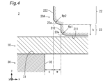
- FIG. 4 is a cross-sectional view showing a schematic configuration of a processing apparatus according to a second embodiment of the present invention.
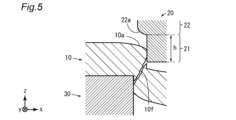
- FIG. 5 is a cross-sectional view that typically illustrates the deformation behavior of a metal plate when the metal plate is sheared by the processing apparatus of FIG.
- FIG. 6 is a cross-sectional view showing a schematic configuration of a processing apparatus according to a third embodiment of the present invention.
- FIG. 7 is a cross-sectional view showing a schematic configuration of a processing apparatus according to a fourth embodiment of the present invention.
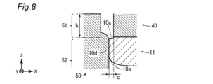
- FIG. 8 is a cross-sectional view that typically shows the configuration of a metal member manufactured by the processing apparatus of FIG.
- FIG. 9 is a graph showing the relationship between the clearance and the sagging, which is obtained by CAE.
- the inventors have investigated the cause of insufficient corrosion resistance of the end face when the workpiece becomes thick in shear processing using a die with a step at the shoulder, as disclosed in JP 2021-133391 A. As a result, they concluded that the cause is that the deformation resistance increases as the workpiece becomes thicker, and the inclination that occurs when the punch is inserted into the workpiece becomes smaller.
- the surface of the workpiece can be significantly tilted during processing, it is possible to reduce the shear caused by the tip of the punch that occurs from the early to middle stages of processing, and to make it less likely that the plating film will be interrupted during shear processing.
- the inventors conducted tests by changing the clearance between the punch and die and the size of the step at the shoulder, and discovered conditions under which the workpiece can be significantly tilted even if it is a thick plate.
- the plating film is less likely to be broken during shearing, and large sagging is formed in the workpiece.
- the sagging is formed when the surface of the plated steel sheet is stretched during shearing, so the plating film on the surface remains thicker than the sheared surface.
- the inventors have discovered that by actively forming sagging on the end faces, the corrosion resistance of the end faces can be further improved.
- FIG. 1 is a cross-sectional view showing a schematic configuration of a processing device 1 according to a first embodiment of the present invention.
- the processing device 1 is a processing device used for shearing a metal plate.
- the shearing process includes, but is not limited to, drilling, punching, cutting, and the like.
- the processing device 1 includes a punch 20 and a die 30.
- the punch 20 and the die 30 are arranged on one side and the other side in the thickness direction of the metal plate 10, which is the workpiece.
- the processing device 1 shears the metal plate 10 by moving at least one of the punch 20 and the die 30 in the thickness direction using a press machine (not shown) or the like so that the punch 20 and the die 30 approach each other.
- the direction parallel to the thickness direction of the metal plate 10 may be referred to as the z direction, and the plane perpendicular to the z direction may be referred to as the xy plane.
- plan view means that the object is viewed straight on from one side in the plate thickness direction. That the punch 20 and the die 30 "do not overlap in a plan view” means that the punch 20 and the die 30 do not overlap when projected onto the xy plane.
- the punch 20 and the die 30 are arranged with a clearance c of 0.20 to 1.80 mm.
- the clearance c is the distance between the punch 20 and the die 30 when they are projected onto the xy plane. More specifically, the clearance c is the distance between the side surface 32 of the die 30 and the side surface 222 of the second blade portion 22 of the punch 20, which will be described later, in the in-plane direction of the metal plate 10. The reason for limiting the clearance c will be described later.
- the punch 20 includes a two-stage shoulder portion. More specifically, the punch 20 includes a first blade portion 21 having a first shoulder portion 21a, and a second blade portion 22 having a second shoulder portion 22a.
- the second shoulder portion 22a is located farther from the metal plate 10 than the first shoulder portion 21a in the thickness direction (z direction) of the metal plate 10, and is located closer to the die 30 than the first shoulder portion 21a in the in-plane direction (direction within the xy plane) of the metal plate 10.
- the first blade portion 21 has an end face 211 and a side face 212 in addition to the first shoulder portion 21a.
- the end face 211 is the face that first comes into contact with the metal plate 10 and is a face that is approximately perpendicular to the plate thickness direction.
- the side face 212 is a face that is approximately parallel to the plate thickness direction.
- the first shoulder 21a is a portion that connects the end face 211 and the side face 212.
- the shape of the first shoulder 21a is not particularly limited, but FIG. 1 illustrates a case where the cross-sectional shape of the first shoulder 21a is almost a right angle (for example, the radius of curvature is less than 0.1 mm).
- the second blade portion 22 has a side surface 222 in addition to the second shoulder portion 22a.
- the side surface 222 is a surface that is approximately parallel to the plate thickness direction.
- the second shoulder 22a is a portion that connects the side surface 212 of the first blade portion 21 and the side surface 222 of the second blade portion 22.
- the radius of curvature Rp2 of the second shoulder 22a is 0.5 to 5.0 mm.
- the dimension of the first blade portion 21 in the thickness direction of the metal plate 10 (hereinafter, this dimension will be referred to as the "step height h") is 1.0 to 6.0 mm, and the distance along the in-plane direction of the metal plate 10 between the side surface 212 of the first blade portion 21 and the side surface 212 of the second blade portion 22 (hereinafter, this dimension will be referred to as the "step width w”) is 0.5 to 5.0 mm.
- the step height h is the distance along the thickness direction between the end surface 211 and the end point of the side surface 212. The reasons for limiting the radius of curvature Rp2, the step height h, and the step width w will be described later.
- the step width w may be smaller than the radius of curvature Rp2 or may be larger than the radius of curvature Rp2.
- the second blade portion 22 may further include a surface connecting the side surface 212 and the second shoulder portion 22a.
- the surface connecting the side surface 212 and the second shoulder portion 22a may be, for example, a surface perpendicular to the plate thickness direction.
- the die 30 includes an end surface 31 and a side surface 32.
- the end surface 31 is the surface that first comes into contact with the metal sheet 10, and is preferably a surface perpendicular to the sheet thickness direction.
- the side surface 32 is a surface that is approximately parallel to the sheet thickness direction.
- the end face 211 of the punch 20 and the end face 31 of the die 30 can each have any planar shape.
- the planar shape of the end face 211 (shape in the xy plane) is, for example, circular, elliptical, rectangular, etc.
- the planar shape of the end face 31 is, for example, a shape with a circular hole, a shape with an elliptical hole, a shape with a rectangular hole, etc.
- the planar shape of end face 211 is preferably circular.
- the planar shape of end face 31 is preferably a shape with a circular hole. In the case of a circular shape, the material is constrained in the circumferential direction, so uniform deformation can be achieved.
- the planar shape of the end faces 211 and 31 may not be a closed shape.
- at least one side of the end face 211 (specifically, the side adjacent to the side face 222) and at least one side of the end face 31 (specifically, the side adjacent to the side face 32) may be parallel to each other.
- the processing device 1 can be used, for example, for punching (drilling) the metal plate 10.
- the planar shape of the end faces 211 and 31 is an open shape, the processing device 1 can be used, for example, for cutting the metal plate 10.
- the size (area) of the end face 211 is not particularly limited.
- the method for manufacturing a metal component according to the present embodiment includes a step of shearing a metal plate covered on both sides with a coating layer (hereinafter referred to as a "surface-coated metal plate") using a processing device 1.
- the base material of the surface-coated metal sheet is, but is not limited to, steel, copper, copper alloy, aluminum, aluminum alloy, etc.
- the manufacturing method according to this embodiment is particularly suitable when the base material of the surface-coated metal sheet is steel. This is because steel is prone to rust, and the advantage of imparting corrosion resistance is great.
- the coating layer is a plating layer, a paint layer, a resin layer, etc.
- a representative surface-coated metal sheet is a plated steel sheet. Examples of plated steel sheets include Zn-based plated steel sheets and Al-based plated steel sheets. In the following explanation, a plating layer will be used as a representative coating layer, and a surface-plated metal sheet will be used as a representative surface-coated metal sheet.
- the surface-plated metal sheet is more preferably a Zn-based plated steel sheet.
- Zn-based plating has a sacrificial corrosion protection effect on the base steel sheet. Therefore, it is possible to suppress corrosion from the exposed part of the base material at the cut end surface caused by shearing, and to further increase the corrosion resistance of the manufactured metal member.
- Examples of Zn-based plating include, but are not limited to, hot-dip galvanizing, alloyed hot-dip galvanizing, Zn-Ni-based plating, Zn-Al-based plating, Zn-Mg-based plating, and Zn-Al-Mg-based plating.
- the thickness of the surface-plated metal sheet is 4.0 to 9.0 mm. Generally, the thicker the sheet, the greater the proportion of fractured surfaces after shearing, making it difficult to impart corrosion resistance by wrapping a plating layer around the end faces after cutting. According to the manufacturing method for a metal component according to this embodiment, even when the sheet is as thick as 4.0 mm or more, high corrosion resistance can be imparted by wrapping a sufficient amount of plating layer around the end faces after cutting.
- the lower limit of the sheet thickness of the surface-plated metal sheet is preferably 4.5 mm, more preferably 5.0 mm, and even more preferably 6.0 mm.
- the upper limit of the sheet thickness of the surface-plated metal sheet is preferably 8.0 mm.
- the thickness of the plating layer of the surface-plated metal sheet is preferably 15 ⁇ m or more. If the plating layer is too thin, the plating layer that can cover the end surface may be depleted, and corrosion resistance may not be imparted to the end surface.
- the lower limit of the thickness of the plating layer of the surface-plated metal sheet is more preferably 30 ⁇ m.
- the upper limit of the thickness of the plating layer of the surface-plated metal sheet is not particularly limited, but is, for example, 150 ⁇ m.
- Figures 2A to 2F are cross-sectional views that show a schematic representation of the deformation behavior of metal sheet 10 (surface-plated metal sheet) when it is sheared by processing device 1.
- punch 20 and die 30 are disposed on one side and the other side of metal sheet 10 in the thickness direction. At least one of punch 20 and die 30 is moved in the thickness direction by a press machine (not shown) or the like so that punch 20 and die 30 approach each other.
- the first blade portion 21 of the punch 20 comes into contact with the metal plate 10. From the time when the first blade portion 21 comes into contact with the metal plate 10 until the second blade portion 22 comes into contact with the metal plate 10, the metal plate 10 is machined by the die 30 and the first blade portion 21 (see Figures 2A and 2B). At this time, the size of the actual clearance between the punch 20 and the die 30 is c + w.
- the clearance c is 0.20 to 1.80 mm
- the step width w is 0.5 to 5.0 mm. Therefore, in this embodiment, the size of c+w is 0.7 to 6.8 mm.
- the step height h is 1.0 to 6.0 mm. In this embodiment, by increasing c+w and increasing the step height h, the surface of the metal plate 10 is inclined more greatly during processing than in the past. This forms a sag 10a in the metal plate 10 that is larger than in the past.
- the radius of curvature Rp2 of the second shoulder portion 22a is 0.5 to 5.0 mm.
- the effect of the first blade portion 21 is to tilt the portion of the metal plate 10 that comes into contact with the second shoulder portion 22a, and to increase the radius of curvature Rp2, thereby making it easier for the plating layer of the metal plate 10 to flow in a direction perpendicular to the thickness direction of the plating layer (see Figure 2C). This allows the plating layer on the surface of the metal plate 10 to wrap around more of the end face of the metal plate 10 after cutting.
- the portion of the metal plate 10 that comes into contact with the first shoulder portion 21a ( Figure 2A) is the portion that will ultimately be cut off, so there is no problem if the plating layer is interrupted at this portion. Therefore, from the perspective of wrapping the plating layer around it, the shape of the first shoulder portion 21a may be any shape.
- the crack 10b develops in the metal plate 10 (see FIG. 2D), and a fracture surface 10c is formed in the metal plate 10 (see FIG. 2E).
- the metal plate 10 is processed by the second blade portion 22, and a shear surface 10d is formed in the metal plate 10 (see FIG. 2F). At this time, part of the fracture surface 10c is covered by the shear surface 10d. This makes it possible to reduce the proportion of the fracture surface 10c in the end surface of the metal plate 10 after cutting.
- the clearance c is 0.20 to 1.80 mm. If the clearance c is too small, the metal plate 10 cannot be inclined sufficiently during processing, and a sag 10a of sufficient size cannot be formed in the metal plate 10. On the other hand, if the clearance c is too large, the metal plate 10 may not be cut completely or large burrs may remain.
- the lower limit of the clearance c is preferably 0.50 mm, and more preferably 0.80 mm.
- the upper limit of the clearance c is preferably 1.60 mm, and more preferably 1.40 mm.
- the clearance c may be 0.2 to 1.8 mm.
- the lower limit of the clearance c may be 0.5 mm or 0.8 mm.
- the upper limit of the clearance c may be 1.6 mm or 1.4 mm.
- the clearance c is preferably set according to the thickness of the metal plate 10. Specifically, the clearance c is preferably set to 5 to 20% of the thickness of the metal plate 10. The lower limit of the clearance c is more preferably 7% of the thickness of the metal plate 10, and even more preferably 10% of the thickness of the metal plate 10. The upper limit of the clearance c is more preferably 18% of the thickness of the metal plate 10, and even more preferably 15% of the thickness of the metal plate 10.
- the step width w is 0.5 to 5.0 mm. If the step width w is too small, the metal plate 10 cannot be sufficiently tilted during processing, and a sag 10a of sufficient size cannot be formed in the metal plate 10. On the other hand, if the step width w is too large, the metal plate 10 may not be sufficiently tilted during processing.
- the lower limit of the step width w is preferably 1.0 mm, and more preferably 2.0 mm.
- the upper limit of the step width w is preferably 4.0 mm.
- the step height h is increased to incline the surface of the metal plate 10 more than in the past during processing.
- the step height h is 1.0 to 6.0 mm. If the step height h is too small, the metal plate 10 cannot be sufficiently inclined during processing, and a sag 10a of sufficient size cannot be formed in the metal plate 10. On the other hand, if the step height h is too large, the metal plate 10 may be cut before the second blade portion 22 comes into contact with the metal plate 10.
- the lower limit of the step height h is preferably 1.5 mm, more preferably 2.0 mm, more preferably 2.5 mm, and even more preferably 3.0 mm.
- the upper limit of the step height h is preferably 5.5 mm, and even more preferably 5.0 mm.
- the radius of curvature Rp2 is increased to allow the plating layer of the metal plate 10 to flow in a direction perpendicular to the thickness direction of the plating layer.
- the radius of curvature Rp2 is 0.5 to 5.0 mm. If the radius of curvature Rp2 is too small, the plating layer is easily broken and a sag 10a of sufficient size cannot be formed on the metal plate 10. In addition, the timing at which the cracks advance may be accelerated, resulting in a large fracture surface. On the other hand, if the radius of curvature Rp2 is too large, burrs may occur during molding using the radius of curvature Rp2.
- the lower limit of the radius of curvature Rp2 is preferably 1.0 mm, more preferably 1.5 mm, and even more preferably 2.0 mm.
- the upper limit of the radius of curvature Rp2 is preferably 4.5 mm, and even more preferably 4.0 mm.
- Metal parts] 3 is a cross-sectional view showing a schematic configuration of a metal member 11 according to one embodiment of the present invention.
- the metal member 11 is a metal member made of a metal plate having a plated layer (coating layer) on both sides and a plated thickness t of 4.0 to 9.0 mm. More specifically, the metal member 11 is obtained by shearing a surface-plated metal plate, which is a workpiece, and has an end face 111 formed by the shearing.
- the metal member 11 has a first surface 112 and a second surface 113, which is the surface opposite the first surface 112.
- the planar shapes (shapes in the xy plane) of the first surface 112 and the second surface 113 may be any shape.
- the first surface 112 and the second surface 113 are covered with a plating layer 10e.
- the plating layer 10e is a plating layer derived from the plating layer of the surface-plated metal plate, which is the material.
- End surface 111 has sagging 111a, sheared surface 111b, and fractured surface 111c.
- Sagging 111a, sheared surface 111b, and fractured surface 111c are formed in this order from first surface 112 toward second surface 113.
- Sagging 111a corresponds to sagging 10a in FIG. 2F
- sheared surface 111b corresponds to sheared surface 10d in FIG. 2F
- fractured surface 111c corresponds to fractured surface 10c in FIG. 2F.
- the surfaces with an inclination angle of 3° or more from the plate thickness direction are called sagging 111a, and the surfaces with an inclination angle of less than 3° are called shear surfaces 111b.
- At least a portion of the shear surface 111b and the sag 111a are covered with a plating layer.
- the sag 111a is a surface formed by stretching the surface of the surface-plated metal sheet, the entire surface is usually covered with a plating layer.
- the thickness of the plating layer covering the sag 111a is greater than the thickness of the plating layer covering the sheared surface 111b. Therefore, by increasing the proportion of the sag 111a in the end surface 111, the corrosion resistance of the end surface 111 can be further improved.
- the dimension of the sag 111a in the z direction (hereinafter, this dimension will be referred to as the "sag length") is 0.18 times or more the plate thickness t.
- the sag length is preferably 0.20 times or more the plate thickness t, more preferably 0.25 times or more the plate thickness t, and even more preferably 0.30 times or more the plate thickness t.
- the upper limit of the sag length is not particularly limited, but is, for example, 0.50 times the plate thickness t.
- the fracture surface 111c is not usually covered with a plating layer. Therefore, by reducing the proportion of the fracture surface 111c in the end surface 111, the corrosion resistance of the end surface 111 can be improved.
- the dimension of the fracture surface 111c in the z direction (hereinafter, this dimension will be referred to as the "fracture surface length") is 0.20 times or less the plate thickness t.
- the fracture surface length is preferably 0.15 times or less the plate thickness t, and more preferably 0.10 times or less.
- the lower limit of the fracture surface length is not particularly limited, but is, for example, 0.05 times the plate thickness t.
- the sheared surface 111b is at least partially covered with a plating layer. It is preferable that 50% or more of the area of the sheared surface 111b is covered with the plating layer, more preferably 75% or more of the area of the sheared surface 111b is covered with the plating layer, and most preferably the entire surface is covered with the plating layer. Whether the sheared surface 111b is covered with a plating layer can be determined, for example, by measuring the sheared surface 111b with an energy dispersive X-ray analyzer (EDX).
- EDX energy dispersive X-ray analyzer
- the plating layer covering at least a portion of the sheared surface 111b and the sagging 111a is a plating layer derived from the plating layer of the surface-plated metal sheet, which is the workpiece, similar to the plating layer 10e covering the first surface 112 and the second surface 113. Therefore, the plating layer covering at least a portion of the sheared surface 111b and the sagging 111a is the same plating layer as the plating layer 10e covering the first surface 112 and the second surface 113.
- the above describes the processing device 1, the method for manufacturing a metal member, and the metal member 11 according to the first embodiment of the present invention. According to this embodiment, a metal member having excellent corrosion resistance at the end surface is obtained.
- the front and back surfaces of the metal sheet 10 are covered with a plating layer, but it is sufficient that at least one of the front and back surfaces of the metal sheet 10 is covered with a plating layer (coating layer).
- the plating layer can be made to wrap around part of the end surface 111 by placing the punch 20 on the surface on which the plating layer is formed and processing it.
- Second Embodiment 4 is a cross-sectional view showing a schematic configuration of a processing device 2 according to a second embodiment of the present invention.
- the processing device 2 is different from the processing device 1 (FIG. 1) according to the first embodiment in the configuration of the punch.
- the processing device 2 includes a punch 20A instead of the punch 20 of the processing device 1.
- Punch 20A includes a first blade portion 23 having a first shoulder portion 23a, and a second blade portion 22 having a second shoulder portion 22a.
- Punch 20A has a similar configuration to punch 20 (Fig. 1) except for the shape of first shoulder portion 23a.
- clearance c, step width w, and step height h are defined in the same way as in the first embodiment, and are 0.20 to 1.80 mm, 0.5 to 5.0 mm, and 1.0 to 6.0 mm, respectively.
- the first shoulder 23a has a radius of curvature Rp1.
- the radius of curvature Rp1 is 0.1 mm or more and 1.0 times the step height h or less.
- the dimension of the side surface 212 in the z direction may be 0.
- the step width w is defined by regarding the end point of the first shoulder 23a as the side surface 212.
- FIG. 5 is a cross-sectional view that shows a schematic representation of the deformation behavior of the metal plate 10 when the metal plate 10 is sheared by the processing device 1 ( Figure 1) according to the first embodiment.
- the step height h is increased, so that the surface of the metal plate 10 is inclined more than in the past during processing, and a larger sag 10a is formed on the surface of the metal plate 10 than in the past.
- the metal plate 10 may be cut before it comes into contact with the second blade portion 22.
- the fracture surface 10f generated at this time is partially covered by the shear surface formed by processing with the second blade portion 22, as explained in FIG. 2F. Therefore, even if the above-mentioned event occurs, the proportion of fracture surfaces can be kept low. On the other hand, if the above-mentioned event occurs, the proportion of the shear surface covered by the coating layer decreases, or the thickness of the coating layer decreases, so that the corrosion resistance of the end surface of the metal component tends to decrease compared to when the above-mentioned event does not occur.
- the first shoulder 23a of the punch 20A has a radius of curvature Rp1. This prevents the metal plate 10 from being cut before it comes into contact with the second blade portion 22. This can further improve the corrosion resistance of the end of the metal member.
- the lower limit of the radius of curvature Rp1 is preferably 0.2 mm, and more preferably 0.5 mm.
- the upper limit of the radius of curvature Rp1 is preferably 0.8 times the step height h, and more preferably 0.6 times the step height h.
- FIG. 6 is a cross-sectional view showing a schematic configuration of a processing device 3 according to a third embodiment of the present invention.
- the processing device 3 is different from the processing device 1 (FIG. 1) according to the first embodiment in the configuration of the punch.
- the processing device 3 includes a punch 20B instead of the punch 20 of the processing device 1.
- Punch 20B includes a first blade portion 24 having a first shoulder portion 24a, and a second blade portion 22 having a second shoulder portion 22a.
- Punch 20B has a similar configuration to punch 20 (Fig. 1) except for the shape of first shoulder portion 24a.
- the clearance c, step width w, and step height h are defined in the same way as in the first embodiment, and are 0.20 to 1.80 mm, 0.5 to 5.0 mm, and 1.0 to 6.0 mm, respectively.
- the first shoulder 24a has a chamfered shape.
- the dimension in the z direction of the chamfered portion of the first shoulder 24a (hereinafter, this dimension will be referred to as the "chamfer length Tc1") is 0.1 mm or more and 1.0 times the step height h or less.
- the chamfer angle (inclination angle from the xy plane) is not limited to this, but is preferably 30 to 60°, and more preferably 40 to 50°.
- the dimension of the side surface 212 in the z direction may be 0.
- the step width w is defined by regarding the end point of the first shoulder 24a as the side surface 212.
- the first shoulder 24a of the punch 20B has a chamfered shape. This prevents the metal plate 10 from being cut before it comes into contact with the second blade portion 22. This can further improve the corrosion resistance of the end of the metal member.
- the lower limit of the chamfer length Tc1 is preferably 0.2 mm, and more preferably 0.5 mm.
- the upper limit of the chamfer length Tc1 is preferably 0.8 times the step height h, and more preferably 0.6 times the step height h.
- [Fourth embodiment] 7 is a cross-sectional view showing a schematic configuration of a processing device 4 according to a fourth embodiment of the present invention.
- the processing device 4 includes a punch 40 instead of the punch 20 of the processing device 1 (FIG. 1), and a die 50 instead of the die 30.
- the die 50 includes a two-stage shoulder portion. More specifically, the die 50 includes a first blade portion 51 having a first shoulder portion 51a and a second blade portion 52 having a second shoulder portion 52a.
- the second shoulder portion 52a is located farther from the metal plate 10 than the first shoulder portion 51a in the thickness direction (z direction) of the metal plate 10, and is located closer to the punch 40 than the first shoulder portion 51a in the in-plane direction (direction within the xy plane) of the metal plate 10.
- the first blade portion 51 has an end face 511 and a side face 512 in addition to a first shoulder portion 51a.
- the second blade portion 52 has a side face 522 in addition to a second shoulder portion 52a.
- the punch 40 includes an end face 41 and a side face 42.
- the clearance c, step width w, and step height h are defined in the same manner as in the first embodiment, and are 0.20 to 1.80 mm, 0.5 to 5.0 mm, and 1.0 to 6.0 mm, respectively.
- the radius of curvature Rp2 of the second shoulder portion 52a is 0.5 to 5.0 mm.
- processing device 4 can also be used for shear processing of surface-plated metal sheets. Specifically, punch 40 and die 50 are placed on one side and the other side of the thickness direction of the surface-plated metal sheet, and at least one of punch 40 and die 50 is moved in the thickness direction so that punch 40 and die 50 approach each other.
- FIG. 8 is a cross-sectional view showing a schematic configuration of the metal member 11 manufactured by the processing device 4. In this embodiment, the portion punched out by the punch 40 becomes the metal member 11.
- the metal member 11 has the same configuration as the metal member 11 ( Figure 3) described in the first embodiment, except for the planar shape (shape in the xy plane). That is, the metal member 11 has a sag 111a, a sheared surface 111b, and a fractured surface 111c on the end surface, and at least a portion of the sheared surface 111b and the sag 111a are covered with a plating layer (coating layer).
- the dimension of the sag 111a in the z direction is 0.18 times or more the plate thickness t
- the dimension of the fractured surface 111c in the z direction is 0.20 times or less the plate thickness t.
- this embodiment also provides a metal component with excellent corrosion resistance at the end face. Note that, as with the second and third embodiments, this embodiment also allows the first shoulder portion 51a to have a predetermined radius of curvature or to have a chamfered shape.
- one of the punch and die includes a two-stage shoulder portion, the effect of improving the corrosion resistance of the end face of the manufactured metal component can be obtained.
- one of the punch and die includes a first blade portion having a first shoulder portion, and a second blade portion having a second shoulder portion that is located farther from the metal plate than the first shoulder portion in the thickness direction of the metal plate and is closer to the other of the punch and die than the first shoulder portion in the in-plane direction of the metal plate.
- Example 1 The relationship between the length of the sag formed when a metal plate with a thickness of 4.5 mm is sheared and the clearance was examined by CAE.
- the mold shapes were set to molds A to E in Table 1.
- the meanings of Rp1, Rp2, w, and h in Table 1 are the same as those in Figure 4.
- Die D imitates the die in JP 2009-287082 A, and has a radius of curvature (Rp1) of the punch tip of 0.5 mm.
- Die E imitates the die in JP 2021-13391 A, and has a two-stage shoulder on the punch, with the radius of curvature Rp2 of the second shoulder being 0.5 mm, the stage width w being 0.5 mm, and the stage height h being 0.8 mm.
- the sagging length is somewhat greater than in mold F, but within the range of clearances normally used, the sagging length is approximately 10-17% of the plate thickness.
- Molds A to C have a larger sagging length than molds D to F.
- the rate at which the sagging length increases as the clearance is expanded is also greater.
- Example 2 Zn-Al-Mg steel sheets having various thicknesses t were sheared using various dies with different clearances c, radius of curvature Rp2 of the second shoulder, step height h, step width w, etc., and the sagging length of the end face and the length of the fractured surface were measured.
- the first shoulder was shaped to have a radius of curvature Rp1 or a chamfer length Tc1. When the first shoulder had a chamfered portion, the chamfer angle was 45°.
- the shearing process in this example was a cutting process with one side 50 mm wide.
- the shearing process in JP 2021-133391 A was a process (punching process) using a square die with one side 40 mm long. In punching processes, the surrounding restraining force is strong, so the sheared surface tends to become long.
- the shearing process (cutting process) in this example is a process under conditions that are more likely to produce a fracture surface than punching processes.
- Samples No. 1 to 23 had a sagging length of 0.18 times or more the plate thickness t, and a fracture surface length of 0.20 times or less the plate thickness t. These samples had excellent rust prevention performance.
- samples made with a mold in which the first shoulder portion had a shape with a curvature radius Rp1 or a shape with a chamfer length Tc1 had particularly excellent rust prevention performance.
- samples No. 24-30, 32, and 33 the sagging length was less than 0.18 times the plate thickness t, and the fracture surface length was greater than 0.20 times the plate thickness t.
- sample No. 31 the sagging length was 0.18 times or more the plate thickness t, but the fracture surface length was greater than 0.20 times the plate thickness t.
- Sample No. 25 was manufactured using a mold simulating Example No. 2 of JP 2021-133391 A, but under these conditions, sufficient sagging length was not obtained.
- Sample No. 26 was manufactured using a mold with a larger clearance than sample No. 25, but under these conditions, the fracture surface could not be sufficiently suppressed.
- Processing device 10 Metal plate 11 Metal member 111 End surface 111a Sagging 111b Shear surface 111c Fracture surface 112 First surface 113 Second surface 20, 40 Punch 21 First blade portion 21a First shoulder portion 211 End surface 212 Side surface 22 Second blade portion 22a Second shoulder portion 222 Side surface 41 End surface 42 Side surface 30, 50 Die 31 End surface 32 Side surface 51 First blade portion 51a First shoulder portion 511 End surface 512 Side surface 52 Second blade portion 52a Second shoulder portion 522 Side surface
Landscapes
- Engineering & Computer Science (AREA)
- Mechanical Engineering (AREA)
- Punching Or Piercing (AREA)
- Shearing Machines (AREA)
Priority Applications (3)
| Application Number | Priority Date | Filing Date | Title |
|---|---|---|---|
| CN202480033750.0A CN121263259A (zh) | 2023-05-29 | 2024-05-15 | 加工装置、金属制构件的制造方法和金属制构件 |
| KR1020257039888A KR20260003208A (ko) | 2023-05-29 | 2024-05-15 | 가공 장치, 금속제 부재의 제조 방법, 및 금속제 부재 |
| JP2025523445A JPWO2024247723A1 (https=) | 2023-05-29 | 2024-05-15 |
Applications Claiming Priority (2)
| Application Number | Priority Date | Filing Date | Title |
|---|---|---|---|
| JP2023087681 | 2023-05-29 | ||
| JP2023-087681 | 2023-05-29 |
Publications (1)
| Publication Number | Publication Date |
|---|---|
| WO2024247723A1 true WO2024247723A1 (ja) | 2024-12-05 |
Family
ID=93657790
Family Applications (1)
| Application Number | Title | Priority Date | Filing Date |
|---|---|---|---|
| PCT/JP2024/017897 Ceased WO2024247723A1 (ja) | 2023-05-29 | 2024-05-15 | 加工装置、金属製部材の製造方法、及び金属製部材 |
Country Status (5)
| Country | Link |
|---|---|
| JP (1) | JPWO2024247723A1 (https=) |
| KR (1) | KR20260003208A (https=) |
| CN (1) | CN121263259A (https=) |
| TW (1) | TWI903524B (https=) |
| WO (1) | WO2024247723A1 (https=) |
Citations (11)
| Publication number | Priority date | Publication date | Assignee | Title |
|---|---|---|---|---|
| JPH0490126U (https=) * | 1990-12-19 | 1992-08-06 | ||
| JP2957512B2 (ja) * | 1997-03-31 | 1999-10-04 | 九州日本電気株式会社 | 半導体装置のリードカット装置 |
| JP2002035861A (ja) * | 2000-07-24 | 2002-02-05 | Nishiyama Tetsumou Seisakusho:Kk | 金属製網材 |
| JP2008155218A (ja) * | 2006-12-21 | 2008-07-10 | Nisshin Steel Co Ltd | 銅めっき鋼板の半抜き加工方法 |
| JP6073025B1 (ja) * | 2015-11-04 | 2017-02-01 | 日新製鋼株式会社 | 切断端面を有する表面処理鋼板の部品およびその切断加工方法 |
| JP2018075600A (ja) * | 2016-11-09 | 2018-05-17 | 日新製鋼株式会社 | 表面処理鋼板の端面の構成、表面処理鋼板の部材、および表面処理鋼板の部材の製造方法 |
| JP2020032437A (ja) * | 2018-08-28 | 2020-03-05 | 日本製鉄株式会社 | 切断加工品 |
| WO2020183882A1 (ja) * | 2019-03-12 | 2020-09-17 | 日本製鉄株式会社 | 切断方法及び切断加工品 |
| JP2020175421A (ja) * | 2019-04-19 | 2020-10-29 | 日本製鉄株式会社 | 表面処理鋼板の切断加工方法 |
| JP2021133391A (ja) * | 2020-02-26 | 2021-09-13 | 日本製鉄株式会社 | 切断加工用金型 |
| WO2023127479A1 (ja) * | 2021-12-28 | 2023-07-06 | 日本製鉄株式会社 | 加工装置、金属製部材の製造方法、及び金属製部材 |
Family Cites Families (2)
| Publication number | Priority date | Publication date | Assignee | Title |
|---|---|---|---|---|
| JPH1131774A (ja) * | 1997-07-10 | 1999-02-02 | Nec Corp | 金属板の切断装置 |
| JP5272518B2 (ja) | 2008-05-29 | 2013-08-28 | Jfeスチール株式会社 | 亜鉛系めっき鋼板、亜鉛系めっき鋼板の切断加工方法および切断加工用金型 |
-
2024
- 2024-05-15 JP JP2025523445A patent/JPWO2024247723A1/ja active Pending
- 2024-05-15 CN CN202480033750.0A patent/CN121263259A/zh active Pending
- 2024-05-15 KR KR1020257039888A patent/KR20260003208A/ko active Pending
- 2024-05-15 WO PCT/JP2024/017897 patent/WO2024247723A1/ja not_active Ceased
- 2024-05-23 TW TW113119065A patent/TWI903524B/zh active
Patent Citations (11)
| Publication number | Priority date | Publication date | Assignee | Title |
|---|---|---|---|---|
| JPH0490126U (https=) * | 1990-12-19 | 1992-08-06 | ||
| JP2957512B2 (ja) * | 1997-03-31 | 1999-10-04 | 九州日本電気株式会社 | 半導体装置のリードカット装置 |
| JP2002035861A (ja) * | 2000-07-24 | 2002-02-05 | Nishiyama Tetsumou Seisakusho:Kk | 金属製網材 |
| JP2008155218A (ja) * | 2006-12-21 | 2008-07-10 | Nisshin Steel Co Ltd | 銅めっき鋼板の半抜き加工方法 |
| JP6073025B1 (ja) * | 2015-11-04 | 2017-02-01 | 日新製鋼株式会社 | 切断端面を有する表面処理鋼板の部品およびその切断加工方法 |
| JP2018075600A (ja) * | 2016-11-09 | 2018-05-17 | 日新製鋼株式会社 | 表面処理鋼板の端面の構成、表面処理鋼板の部材、および表面処理鋼板の部材の製造方法 |
| JP2020032437A (ja) * | 2018-08-28 | 2020-03-05 | 日本製鉄株式会社 | 切断加工品 |
| WO2020183882A1 (ja) * | 2019-03-12 | 2020-09-17 | 日本製鉄株式会社 | 切断方法及び切断加工品 |
| JP2020175421A (ja) * | 2019-04-19 | 2020-10-29 | 日本製鉄株式会社 | 表面処理鋼板の切断加工方法 |
| JP2021133391A (ja) * | 2020-02-26 | 2021-09-13 | 日本製鉄株式会社 | 切断加工用金型 |
| WO2023127479A1 (ja) * | 2021-12-28 | 2023-07-06 | 日本製鉄株式会社 | 加工装置、金属製部材の製造方法、及び金属製部材 |
Also Published As
| Publication number | Publication date |
|---|---|
| TWI903524B (zh) | 2025-11-01 |
| KR20260003208A (ko) | 2026-01-06 |
| TW202500288A (zh) | 2025-01-01 |
| JPWO2024247723A1 (https=) | 2024-12-05 |
| CN121263259A (zh) | 2026-01-02 |
Similar Documents
| Publication | Publication Date | Title |
|---|---|---|
| US20250235938A1 (en) | Cutting method and cut article | |
| US11123785B2 (en) | Surface-treated steel sheet part having cut end surface, and cutting method therefor | |
| JP7140298B2 (ja) | 加工品及び加工品製造方法 | |
| CN108290199A (zh) | 用于加工和/或制造构件的方法和设备以及这样的构件 | |
| JP7777274B2 (ja) | 金属製部材の製造方法、金型、及び金属製部材 | |
| JP7617483B2 (ja) | 加工装置、金属製部材の製造方法、及び金属製部材 | |
| WO2024247723A1 (ja) | 加工装置、金属製部材の製造方法、及び金属製部材 | |
| Yasutomi et al. | Effect of Crack Propagation on Residual Stress of Sheared Edge | |
| JPH01293922A (ja) | 金属板のバリ無打抜き型及び加工方法 | |
| JP7406091B2 (ja) | 切断加工用金型及び切断加工部品の製造方法 | |
| JP2008155218A (ja) | 銅めっき鋼板の半抜き加工方法 | |
| EP4414111A1 (en) | Cutting device and multi-layer material | |
| JPH0857557A (ja) | 金属板の打ち抜き型および加工方法 | |
| HK40108568A (zh) | 加工装置、金属制构件的制造方法和金属制构件 | |
| JP7678380B2 (ja) | 加工材の製造方法及び加工材 | |
| WO2025018081A1 (ja) | 金属製加工品の製造方法及び金属製加工品 | |
| Chanhee et al. | Effect of two-stage press blanking on edge stretchability with third-generation advanced high-strength steels | |
| WO2025004910A1 (ja) | 金属製加工品の製造方法及び金属製加工品 | |
| HK40105792A (zh) | 切割装置和多层材料 | |
| HK40128290A (zh) | 金属制加工品的制造方法以及金属制加工品 | |
| RU2542034C2 (ru) | Способ формовки патрубков в листовых деталях | |
| JPH08332528A (ja) | 金属板材用試験片の加工方法 | |
| JPH10118724A (ja) | 疲労耐久性に優れた厚手鋼板の打抜方法 |
Legal Events
| Date | Code | Title | Description |
|---|---|---|---|
| 121 | Ep: the epo has been informed by wipo that ep was designated in this application |
Ref document number: 24815207 Country of ref document: EP Kind code of ref document: A1 |
|
| ENP | Entry into the national phase |
Ref document number: 2025523445 Country of ref document: JP Kind code of ref document: A |
|
| WWE | Wipo information: entry into national phase |
Ref document number: 2025523445 Country of ref document: JP |
|
| WWE | Wipo information: entry into national phase |
Ref document number: CN2024800337500 Country of ref document: CN |
|
| ENP | Entry into the national phase |
Ref document number: 1020257039888 Country of ref document: KR Free format text: ST27 STATUS EVENT CODE: A-0-1-A10-A15-NAP-PA0105 (AS PROVIDED BY THE NATIONAL OFFICE) |
|
| NENP | Non-entry into the national phase |
Ref country code: DE |