WO2024247362A1 - 容器及び容器製造方法 - Google Patents
容器及び容器製造方法 Download PDFInfo
- Publication number
- WO2024247362A1 WO2024247362A1 PCT/JP2024/002569 JP2024002569W WO2024247362A1 WO 2024247362 A1 WO2024247362 A1 WO 2024247362A1 JP 2024002569 W JP2024002569 W JP 2024002569W WO 2024247362 A1 WO2024247362 A1 WO 2024247362A1
- Authority
- WO
- WIPO (PCT)
- Prior art keywords
- flange portion
- flange
- curled
- container
- sealing
- Prior art date
- Legal status (The legal status is an assumption and is not a legal conclusion. Google has not performed a legal analysis and makes no representation as to the accuracy of the status listed.)
- Ceased
Links
Images


Classifications
-
- B—PERFORMING OPERATIONS; TRANSPORTING
- B65—CONVEYING; PACKING; STORING; HANDLING THIN OR FILAMENTARY MATERIAL
- B65D—CONTAINERS FOR STORAGE OR TRANSPORT OF ARTICLES OR MATERIALS, e.g. BAGS, BARRELS, BOTTLES, BOXES, CANS, CARTONS, CRATES, DRUMS, JARS, TANKS, HOPPERS, FORWARDING CONTAINERS; ACCESSORIES, CLOSURES, OR FITTINGS THEREFOR; PACKAGING ELEMENTS; PACKAGES
- B65D3/00—Rigid or semi-rigid containers having bodies or peripheral walls of curved or partially-curved cross-section made by winding or bending paper without folding along defined lines
- B65D3/02—Rigid or semi-rigid containers having bodies or peripheral walls of curved or partially-curved cross-section made by winding or bending paper without folding along defined lines characterised by shape
- B65D3/06—Rigid or semi-rigid containers having bodies or peripheral walls of curved or partially-curved cross-section made by winding or bending paper without folding along defined lines characterised by shape essentially conical or frusto-conical
-
- B—PERFORMING OPERATIONS; TRANSPORTING
- B31—MAKING ARTICLES OF PAPER, CARDBOARD OR MATERIAL WORKED IN A MANNER ANALOGOUS TO PAPER; WORKING PAPER, CARDBOARD OR MATERIAL WORKED IN A MANNER ANALOGOUS TO PAPER
- B31B—MAKING CONTAINERS OF PAPER, CARDBOARD OR MATERIAL WORKED IN A MANNER ANALOGOUS TO PAPER
- B31B50/00—Making rigid or semi-rigid containers, e.g. boxes or cartons
- B31B50/60—Uniting opposed surfaces or edges; Taping
- B31B50/62—Uniting opposed surfaces or edges; Taping by adhesives
-
- B—PERFORMING OPERATIONS; TRANSPORTING
- B31—MAKING ARTICLES OF PAPER, CARDBOARD OR MATERIAL WORKED IN A MANNER ANALOGOUS TO PAPER; WORKING PAPER, CARDBOARD OR MATERIAL WORKED IN A MANNER ANALOGOUS TO PAPER
- B31B—MAKING CONTAINERS OF PAPER, CARDBOARD OR MATERIAL WORKED IN A MANNER ANALOGOUS TO PAPER
- B31B50/00—Making rigid or semi-rigid containers, e.g. boxes or cartons
- B31B50/74—Auxiliary operations
-
- B—PERFORMING OPERATIONS; TRANSPORTING
- B65—CONVEYING; PACKING; STORING; HANDLING THIN OR FILAMENTARY MATERIAL
- B65D—CONTAINERS FOR STORAGE OR TRANSPORT OF ARTICLES OR MATERIALS, e.g. BAGS, BARRELS, BOTTLES, BOXES, CANS, CARTONS, CRATES, DRUMS, JARS, TANKS, HOPPERS, FORWARDING CONTAINERS; ACCESSORIES, CLOSURES, OR FITTINGS THEREFOR; PACKAGING ELEMENTS; PACKAGES
- B65D29/00—Sacks or like containers made of fabrics; Flexible containers of open-work, e.g. net-like construction
-
- B—PERFORMING OPERATIONS; TRANSPORTING
- B65—CONVEYING; PACKING; STORING; HANDLING THIN OR FILAMENTARY MATERIAL
- B65D—CONTAINERS FOR STORAGE OR TRANSPORT OF ARTICLES OR MATERIALS, e.g. BAGS, BARRELS, BOTTLES, BOXES, CANS, CARTONS, CRATES, DRUMS, JARS, TANKS, HOPPERS, FORWARDING CONTAINERS; ACCESSORIES, CLOSURES, OR FITTINGS THEREFOR; PACKAGING ELEMENTS; PACKAGES
- B65D3/00—Rigid or semi-rigid containers having bodies or peripheral walls of curved or partially-curved cross-section made by winding or bending paper without folding along defined lines
- B65D3/10—Rigid or semi-rigid containers having bodies or peripheral walls of curved or partially-curved cross-section made by winding or bending paper without folding along defined lines characterised by form of integral or permanently secured end closure
- B65D3/12—Flanged discs permanently secured, e.g. by adhesives or by heat-sealing
- B65D3/14—Discs fitting within container end and secured by bending, rolling, or folding operations
-
- B—PERFORMING OPERATIONS; TRANSPORTING
- B65—CONVEYING; PACKING; STORING; HANDLING THIN OR FILAMENTARY MATERIAL
- B65D—CONTAINERS FOR STORAGE OR TRANSPORT OF ARTICLES OR MATERIALS, e.g. BAGS, BARRELS, BOTTLES, BOXES, CANS, CARTONS, CRATES, DRUMS, JARS, TANKS, HOPPERS, FORWARDING CONTAINERS; ACCESSORIES, CLOSURES, OR FITTINGS THEREFOR; PACKAGING ELEMENTS; PACKAGES
- B65D77/00—Packages formed by enclosing articles or materials in preformed containers, e.g. boxes, cartons, sacks or bags
- B65D77/10—Container closures formed after filling
- B65D77/20—Container closures formed after filling by applying separate lids or covers, i.e. flexible membrane or foil-like covers
- B65D77/2024—Container closures formed after filling by applying separate lids or covers, i.e. flexible membrane or foil-like covers the cover being welded or adhered to the container
-
- B—PERFORMING OPERATIONS; TRANSPORTING
- B31—MAKING ARTICLES OF PAPER, CARDBOARD OR MATERIAL WORKED IN A MANNER ANALOGOUS TO PAPER; WORKING PAPER, CARDBOARD OR MATERIAL WORKED IN A MANNER ANALOGOUS TO PAPER
- B31B—MAKING CONTAINERS OF PAPER, CARDBOARD OR MATERIAL WORKED IN A MANNER ANALOGOUS TO PAPER
- B31B2105/00—Rigid or semi-rigid containers made by assembling separate sheets, blanks or webs
- B31B2105/002—Making boxes characterised by the shape of the blanks from which they are formed
- B31B2105/0022—Making boxes from tubular webs or blanks, e.g. with separate bottoms, including tube or bottom forming operations
-
- B—PERFORMING OPERATIONS; TRANSPORTING
- B31—MAKING ARTICLES OF PAPER, CARDBOARD OR MATERIAL WORKED IN A MANNER ANALOGOUS TO PAPER; WORKING PAPER, CARDBOARD OR MATERIAL WORKED IN A MANNER ANALOGOUS TO PAPER
- B31B—MAKING CONTAINERS OF PAPER, CARDBOARD OR MATERIAL WORKED IN A MANNER ANALOGOUS TO PAPER
- B31B2110/00—Shape of rigid or semi-rigid containers
- B31B2110/10—Shape of rigid or semi-rigid containers having a cross section of varying size or shape, e.g. conical or pyramidal
-
- B—PERFORMING OPERATIONS; TRANSPORTING
- B31—MAKING ARTICLES OF PAPER, CARDBOARD OR MATERIAL WORKED IN A MANNER ANALOGOUS TO PAPER; WORKING PAPER, CARDBOARD OR MATERIAL WORKED IN A MANNER ANALOGOUS TO PAPER
- B31B—MAKING CONTAINERS OF PAPER, CARDBOARD OR MATERIAL WORKED IN A MANNER ANALOGOUS TO PAPER
- B31B2110/00—Shape of rigid or semi-rigid containers
- B31B2110/20—Shape of rigid or semi-rigid containers having a curved cross section, e.g. circular
-
- B—PERFORMING OPERATIONS; TRANSPORTING
- B31—MAKING ARTICLES OF PAPER, CARDBOARD OR MATERIAL WORKED IN A MANNER ANALOGOUS TO PAPER; WORKING PAPER, CARDBOARD OR MATERIAL WORKED IN A MANNER ANALOGOUS TO PAPER
- B31B—MAKING CONTAINERS OF PAPER, CARDBOARD OR MATERIAL WORKED IN A MANNER ANALOGOUS TO PAPER
- B31B2120/00—Construction of rigid or semi-rigid containers
- B31B2120/002—Construction of rigid or semi-rigid containers having contracted or rolled necks, having shoulders
-
- B—PERFORMING OPERATIONS; TRANSPORTING
- B31—MAKING ARTICLES OF PAPER, CARDBOARD OR MATERIAL WORKED IN A MANNER ANALOGOUS TO PAPER; WORKING PAPER, CARDBOARD OR MATERIAL WORKED IN A MANNER ANALOGOUS TO PAPER
- B31B—MAKING CONTAINERS OF PAPER, CARDBOARD OR MATERIAL WORKED IN A MANNER ANALOGOUS TO PAPER
- B31B2120/00—Construction of rigid or semi-rigid containers
- B31B2120/10—Construction of rigid or semi-rigid containers provided with covers, e.g. lids
Definitions
- the present invention relates to containers for food and beverages and methods for manufacturing the same.
- containers for food and beverages have been widely used that are made of sheet-like material and have a body with a side seam (bonded part) and a bottom attached to the inside of the body, with the open end sealed with a film-like sealing material (top sealing material).
- the open end of the container has a flange that faces the outside of the container, and after the container is filled with the beverage or other contents, a sealant is attached to the flange, for example by heat sealing.
- Patent Document 1 describes how the flange portion (mouth roll) is formed so that its cross section is circular (curled).
- Patent Document 2 describes how the flange portion (cup rim portion) is pressed from above and below to form a flat shape.
- the flange portion may deform when the sealant is sealed, causing the outer diameter of the opening to change, which may result in poor fit of the lid (overcap) that is fitted to the flange portion.
- the flange portion may deform when the sealant is opened, making it impossible to open stably, and the fit of the lid may become poor as described above.
- the object of the present invention is to provide a container and a method for manufacturing the container that can suppress deformation of the flange portion (deformation of the outer diameter of the mouth) when sealing and unsealing the sealing material, and that allows the sealing material to be easily unsealed even under strong sealing conditions.
- a container in order to achieve the above object, comprises a cylindrical body portion formed from a body member, a flange portion formed by rolling one end of the body member outward, a bottom portion formed by the other end of the body member and a bottom member, and a sealing material having a thermoplastic resin bonded to the upper surface of the flange portion by heat sealing.
- the flange portion has a first curl portion located at the outermost periphery in the radial direction of the body portion, and a second curl portion overlapping the first curl portion on the inside.
- the flange portion also has an adhesive portion bonding the first curl portion and the second curl portion together in at least one location when viewed in cross section in the radial direction, and has a space inside the second curl portion that is equal to or greater than the thickness of the paper material.
- the adhesive portion between the first curled portion and the second curled portion by providing a space inside the second curled portion, the space acts as a cushion when the sealant is heat sealed (springback effect), and when the space is once crushed by the seal head, a resin puddle formed between the flange portion and the sealant peels off as the space returns to its original size, forming a notch, which becomes the point of action when opening, making it possible to easily open the sealant even under strong sealing conditions.
- the thickness of the paper material is, for example, about 0.3 mm, but is not limited to this.
- the container may have a resin reservoir between the flange and the sealing material, formed by the thermoplastic resin melted during the heat sealing, and a notch between the resin reservoir and the flange, formed by the resin reservoir peeling off from the flange due to the springback effect of the space during the heat sealing.
- the flange portion may have a first length in the height direction and a second length in the width direction that is greater than the first length.
- the flange is given a more flattened shape than the conventional round curl shape, which further suppresses deformation of the flange when sealing and unsealing the sealant, and stabilizes the outer diameter of the opening.
- the flange portion may have a step portion of a predetermined height and width at the outer peripheral edge of its upper surface.
- the adhesive portion may be provided closer to the boundary between the flange portion and the side surface of the body than the end of the body member that is rolled outward.
- a method for manufacturing a container includes the steps of: The sides of the body member are joined to form a cylindrical body portion; one end of the body member and a bottom member are joined to form a bottom portion; The other end of the body member is rolled outward to form a curled flange portion; a first curled portion of the flange portion located at the outermost periphery in the radial direction of the body portion and a second curled portion overlapping the first curled portion on the inside are bonded to each other to form a space on the inside of the second curled portion that is equal to or larger than the thickness of the paper material; and adhering a sealant to the upper surface of the flange portion by heat sealing.
- FIG. 1 is a diagram showing a front appearance of a paper cup according to one embodiment of the present invention.
- FIG. 2 is an enlarged cross-sectional view of a flange portion in FIG. 1 .
- FIG. 11 is a diagram showing experimental results of the openability of the flange portion in comparison with a comparative example.
- FIG. 13 is a diagram showing a relationship curve between elapsed time (opening position) when opening the flange portion and opening strength in comparison with a comparative example.
- 11 is a diagram showing the state of the resin pool on the outer periphery of the flange portion in comparison with a comparative example.
- FIG. 5A to 5C are cross-sectional views showing changes in the state of the flange portion during top sealing.
- 4 is a flowchart showing a manufacturing process of the paper cup.
- FIG. 1 is a diagram showing the front appearance of a paper cup as a container according to one embodiment of the present invention, with a portion of the figure shown in cross section.
- the paper cup 100 of this embodiment has a body 1 and a bottom 2.
- the body 1 is made by coating (laminating) the raw paper material (base paper) with a thermoplastic resin such as polyethylene, polypropylene, or polyester, punching out a sector-shaped blank (body member), wrapping it around a cylindrical mold, and gluing the side ends together. By gluing the side ends together in this way, a side seam 4 is formed on the top and bottom of the side of the body 1.
- a thermoplastic resin such as polyethylene, polypropylene, or polyester
- the bottom 2 is made by drawing a circular bottom paper (bottom member) punched out from the same paper material as the body 1, and gluing it to the inside of the lower end of the body 1 at the same time as gluing the body 1.
- the lower end of the body 1, to which the bottom 2 is attached, has the paper folded inward and pressed.
- the upper end of the body 1 has a flange 3 formed by folding one end of the body material outward, and the body 1 is open at this flange 3.
- a sealing material such as polyethylene film is heat sealed to the flange portion 3, sealing the paper cup 100.
- the paper material used as the raw material for the body 1 and bottom 2 is composed of, for example, multiple layers.
- the paper material may also be laminated with a synthetic resin layer, a foam layer, a metal layer, an inorganic vapor deposition film, etc.
- the body 1 and bottom 2 may be further laminated with a resin film such as polyethylene terephthalate.
- FIG. 2 is an enlarged cross-sectional view of the flange portion 3 (part E in FIG. 1).
- the flange portion 3 has a sealing surface 31 to which the sealing material is adhered, a curled portion 32 into which the body portion 1 is rolled, and a step portion 33.
- the width (length in the X direction) A of the flange portion 3 is greater than the height (thickness: length in the Y direction) B of the flange portion 3.
- the flange portion 3 of this embodiment has a shape that is flattened in the height direction (Y direction).
- the width A of the flange portion 3 is, for example, 2 to 5 mm, and the thickness B of the flange portion 3 is approximately 1 to 1.5 mm, which is at least four times the thickness T of the paper material (for example, 0.3 mm).
- Flange portion 3 also has a first curled portion 34 located at the outermost periphery in the radial direction (X direction) of body portion 1, and a second curled portion 35 overlapping the first curled portion 34 on the inside.
- Flange portion 3 also has an adhesive portion 36 that bonds between first curled portion 34 and second curled portion 35, in only one location when viewed in cross section in the radial direction. In other words, curled portion 32 of flange portion 3 is bonded only by this one adhesive portion 36.
- the adhesive portion 36 can prevent the curl of the flange portion 3 from turning over when the seal material is opened.
- the adhesive portion 36 is preferably provided closer to the boundary between the flange portion 3 and the side of the body portion 1 (the left side in Figure 2) than the rolled end of the paper material. This can further enhance the curl prevention effect.
- a space S is formed inside the second curled portion 35 of the flange portion 3.
- the space S is formed as a result of bonding the curled portion 32 only with the adhesive portion 36 (the second curled portion 35 is not bonded to the layer below).
- the space S is secured in the Y direction to be equal to or larger than the thickness T of the paper material (about twice the thickness T in the example shown in the figure).
- the step portion 33 is formed on the outer peripheral edge of the upper surface of the flange portion 3. As will be described later, the step portion 33 is formed by press molding the outer peripheral edge of the curled flange portion.
- the seal head does not come into contact with the step 33 but only comes into contact with the inside of the flange 3 (seal surface 31) (or if it does come into contact, it is only weak contact), preventing deformation of the flange 3.
- the point of action of the opening force relative to the fulcrum is more inward than the outer circumferential edge of the flange 3 (the starting point of the step 33), so the moment of force is smaller, which is effective in making it easier to open (easy peel).
- deformation of the flange 3 can be suppressed by performing a press process on the curl (by crushing it once before sealing).
- the height D of the step portion 33 (the distance between the sealing surface 31 and the bottom surface of the step portion 33) is approximately equal to the thickness T of the paper material, but is not limited to this and may be approximately half the thickness T.
- the width C of the step 33 (the distance from the boundary between the sealing surface 31 and the step 33 to the outer peripheral edge of the flange 3) is, for example, about one-quarter to one-third of the width A of the flange 3. If the sealing conditions are appropriate (the area around the step 33 is not strongly sealed), a larger width C reduces the moment required to open, improving ease of opening.
- [Easy opening of flange] 3 is a diagram showing the results of an experiment on the openability of the sealing material of the flange portion 3 in comparison with a comparative example.
- the layers of the flange portion are bonded at multiple points to prevent the formation of the space S.
- the sealing material was sealed under the following sealing conditions: temperature 165°C, load 130 kg/cup, and two compression cycles.
- the sealing load for paper cups is generally around 60 kg/cup, so the above conditions can be considered strong sealing conditions (this sealing load is equivalent to the sealing load for a plastic (PET) cup).
- the flange portion of the comparative example could not be opened even once, whereas the flange portion 3 of this embodiment was successfully opened all five times with a stable opening strength of maximum 26 N, minimum 22 N, and average 24 N.
- the flange portion 3 makes it possible to stably open the seal even under strong sealing conditions.
- Figure 4 is a graph showing the relationship between the elapsed time (opening position) when opening the flange portion 3 and the opening strength, in comparison with the comparative example. Note that the flange portion in the comparative example cannot be opened under the strong sealing conditions as shown in Figure 3 above, and therefore the opening strength cannot be measured. Therefore, in the experiment in Figure 4, the flange portion was sealed under appropriate sealing conditions, not strong sealing conditions.
- a peak of 14 N occurs at the boundary between the body portion and the flange portion, which is the fulcrum of the force for opening the sealant
- a strong peak of 16 N occurs at the outer circumferential edge of the flange portion, which is the point of application of the opening force. It is believed that the high opening strength at the outer circumferential edge, which is the point of application of this opening force, leads to the above-mentioned opening failure under strong seal conditions.
- the opening strength at the action point on the outer periphery is 10 N, and it can be seen that no strong peak that could lead to opening failure occurs on the outer periphery.
- the flange portion 3 of this embodiment has high openability even under the strong sealing conditions described above (particularly the opening strength does not increase on the outer periphery).
- Figure 5 shows the state of the resin pool on the outer periphery of the flange portion 3 in comparison with the comparative example.
- the resin pool at the boundary with the sealing material has peeled off, forming a notch between the sealing material (resin pool) and the flange portion 3.
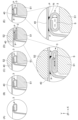
- Figure 6 is a cross-sectional view showing the change in state of the flange portion 3 when top sealing is performed.
- (A) in the figure shows the unsealed state, followed by (B) to (D), and finally (E) showing the state when top sealing is completed.
- the lower part of the figure shows an enlarged view of (D) and (E).
- the flange portion 3 is set in the sealing bucket S1 as shown in FIG. 3(B) from the unsealed state shown in FIG. 3(A), and the sealing material 40 is set on the sealing surface 31 of the flange portion 3.
- the seal head S2 comes into contact with the seal material 40 from above, presses it while heating it as shown in FIG. 4(D), and then rises as shown in FIG. 4(E), welding the seal material 40 to the flange portion 3 and completing the heat seal.
- the paper cup 100 sealed with the sealing material 40 in this embodiment has a resin reservoir P between the flange and the sealing material 40, which is formed by the thermoplastic resin melted during heat sealing, and a notch N between the resin reservoir P and the flange 3, which is formed when the resin reservoir P peels off from the flange 3 due to the springback effect of the space S during heat sealing.
- the notch N thus formed becomes the point of application of the opening force when the sealing material 40 is opened, making it possible to easily open the sealing material 40 even under strong sealing conditions.
- Fig. 7 is a flow chart showing the flow of the manufacturing process for the paper cup 100.
- a fan-shaped blank is punched out from the paper material laminated with the thermoplastic resin, and both ends of the blank are melted with a gas burner or the like and then wrapped around a cylindrical mold and glued together to form the body 1 (step 61).
- a circular bottom paper punched out from the same paper material as above is drawn and vacuum-adsorbed to the cylindrical mold.
- the ends of the body 1 are bonded to each other and at the same time, the bottom 2 is bonded to the inside of the body 1.
- the bottom end of the body 1 is then folded toward the bottom 2 and crimped, thereby joining the bottom 2 to the body 1 (step 62).
- the upper end of the body 1 is curled outward while being rotated by a tool through a curling process, forming a flange portion (round curl) whose cross section in the radial direction (X direction) of the body 1 is circular (step 63).
- the vicinity of its upper end is rolled up in a circumferential direction in a molten state using hot air, a gas burner, ultrasonic waves, etc., thereby bonding the first curled portion 34 and the second curled portion 35 together and forming the adhesive portion 36.
- a space S is also formed inside the second curled portion 35.
- the circular cross-sectional flange portion is pressed using a mold with a convex portion formed on its outer peripheral edge to form a step portion 33 and a flange portion 3 that is crushed in the height direction (horizontal cross-section) (step 64).
- the paper cup 100 is filled with ice, beverages, or other contents, and the sealant 40 is heat sealed to adhere to the opening (seal surface 31 of the flange portion 3) as shown in FIG. 6, thereby sealing the paper cup 100 (step 65).
- the cushioning effect (springback effect) of the space S in the flange portion 3 forms a notch N from the resin pool P in the step portion 33. This improves ease of opening.
- the stepped portion 33 is not heat sealed, the point of action when opening can be positioned further inward, and since resin flows into the stepped portion 33 during heat sealing and a resin pool P is easily formed, a notch N is easily formed, further improving the ease of opening.
- the adhesive portion 36 of the flange portion 3 is provided in only one location between the first curl portion 34 and the second curl portion 35 in the radial direction (X direction) of the body portion 1.
- the adhesive portion 36 may be provided in multiple locations between the first curl portion 34 and the second curl portion 35.
- the adhesive portion 36 is provided in only one location.
- the adhesive portion 36 of the flange portion 3 is formed when the round curl is rolled in, but the adhesive portion 36 may be formed by pressing with an ultrasonic horn or the like during the press processing for forming the step portion 33 after the round curl is rolled in.
- the shapes of the flange portion 3 and the step portion 33 are not limited to those shown in FIG. 2.
- the step portion 33 shown in FIG. 2 is composed of a bottom surface that is nearly parallel to the sealing surface 31 and a slope that connects the sealing surface 31 and the bottom surface, but the slope may be a surface that is closer to vertical, and the bottom surface may be formed wider.
- the body 1 and bottom 2 are manufactured as separate parts, and the bottom 2 is glued to the body 1 to produce the paper cup 100.
- a container such as a paper cup may also be manufactured by forming the body and bottom integrally from a single sheet of paper material, and even in this case the flange portion can be molded in the same manner as in the above-described embodiment.
- the paper cup 100 is formed by molding the body 1 having the side seam 4 and the bottom 2 from paper material that has been coated with thermoplastic resin in advance, and then connecting the two.
- the paper cup 100 may be formed by molding the body and bottom from paper material that is not coated with thermoplastic resin, joining the body (side seam) and the bottom with resin (adhesive) to form a paper container, and attaching a resin film to the inner surface of the paper container by vacuum and/or pressure molding.
- a paper cup 100 is shown as a container, but the use of the container is not limited to a cup, and it may be used to hold food such as sweets, for example.
Landscapes
- Engineering & Computer Science (AREA)
- Mechanical Engineering (AREA)
- Packages (AREA)
Priority Applications (4)
| Application Number | Priority Date | Filing Date | Title |
|---|---|---|---|
| EP24814849.6A EP4722117A1 (en) | 2023-05-29 | 2024-01-29 | Container and container manufacturing method |
| KR1020257039104A KR20260003058A (ko) | 2023-05-29 | 2024-01-29 | 용기 및 용기 제조방법 |
| JP2025523254A JPWO2024247362A1 (https=) | 2023-05-29 | 2024-01-29 | |
| CN202480033996.8A CN121263363A (zh) | 2023-05-29 | 2024-01-29 | 容器和容器制造方法 |
Applications Claiming Priority (2)
| Application Number | Priority Date | Filing Date | Title |
|---|---|---|---|
| JP2023087646 | 2023-05-29 | ||
| JP2023-087646 | 2023-05-29 |
Publications (1)
| Publication Number | Publication Date |
|---|---|
| WO2024247362A1 true WO2024247362A1 (ja) | 2024-12-05 |
Family
ID=93657664
Family Applications (1)
| Application Number | Title | Priority Date | Filing Date |
|---|---|---|---|
| PCT/JP2024/002569 Ceased WO2024247362A1 (ja) | 2023-05-29 | 2024-01-29 | 容器及び容器製造方法 |
Country Status (5)
| Country | Link |
|---|---|
| EP (1) | EP4722117A1 (https=) |
| JP (1) | JPWO2024247362A1 (https=) |
| KR (1) | KR20260003058A (https=) |
| CN (1) | CN121263363A (https=) |
| WO (1) | WO2024247362A1 (https=) |
Citations (5)
| Publication number | Priority date | Publication date | Assignee | Title |
|---|---|---|---|---|
| JPS5726315U (https=) * | 1980-07-23 | 1982-02-10 | ||
| JP2004042987A (ja) | 2002-07-15 | 2004-02-12 | Toppan Printing Co Ltd | 飲料用紙カップ及びその製造方法 |
| JP2008507458A (ja) | 2004-07-26 | 2008-03-13 | ストラ エンソ オーワイジェイ | プラスチックで被覆した厚紙のカップにマウスロールを作る方法およびこの方法で作ったカップ |
| WO2016013254A1 (ja) * | 2014-07-24 | 2016-01-28 | 東罐興業株式会社 | 容器及び容器製造方法 |
| JP2016078868A (ja) * | 2014-10-14 | 2016-05-16 | 日清食品ホールディングス株式会社 | 紙製容器 |
-
2024
- 2024-01-29 EP EP24814849.6A patent/EP4722117A1/en active Pending
- 2024-01-29 CN CN202480033996.8A patent/CN121263363A/zh active Pending
- 2024-01-29 KR KR1020257039104A patent/KR20260003058A/ko active Pending
- 2024-01-29 WO PCT/JP2024/002569 patent/WO2024247362A1/ja not_active Ceased
- 2024-01-29 JP JP2025523254A patent/JPWO2024247362A1/ja active Pending
Patent Citations (5)
| Publication number | Priority date | Publication date | Assignee | Title |
|---|---|---|---|---|
| JPS5726315U (https=) * | 1980-07-23 | 1982-02-10 | ||
| JP2004042987A (ja) | 2002-07-15 | 2004-02-12 | Toppan Printing Co Ltd | 飲料用紙カップ及びその製造方法 |
| JP2008507458A (ja) | 2004-07-26 | 2008-03-13 | ストラ エンソ オーワイジェイ | プラスチックで被覆した厚紙のカップにマウスロールを作る方法およびこの方法で作ったカップ |
| WO2016013254A1 (ja) * | 2014-07-24 | 2016-01-28 | 東罐興業株式会社 | 容器及び容器製造方法 |
| JP2016078868A (ja) * | 2014-10-14 | 2016-05-16 | 日清食品ホールディングス株式会社 | 紙製容器 |
Non-Patent Citations (1)
| Title |
|---|
| See also references of EP4722117A1 |
Also Published As
| Publication number | Publication date |
|---|---|
| EP4722117A1 (en) | 2026-04-08 |
| JPWO2024247362A1 (https=) | 2024-12-05 |
| KR20260003058A (ko) | 2026-01-06 |
| CN121263363A (zh) | 2026-01-02 |
Similar Documents
| Publication | Publication Date | Title |
|---|---|---|
| US10207829B2 (en) | Funnel component and manufacturing method for manufacturing packaging container using funnel component | |
| JPH01279056A (ja) | 易開封性蓋 | |
| CA2778253A1 (en) | Container assembly having a heat-sealed metal end, a metal end therefor, and a method for making same | |
| JP6315728B2 (ja) | 容器及び容器製造方法 | |
| EP3962820A1 (en) | Container with paperboard outer layer and thin plastic foil inner layer | |
| WO2024247362A1 (ja) | 容器及び容器製造方法 | |
| JP3208007B2 (ja) | 易開封性密封容器 | |
| JP7735532B2 (ja) | 容器及び容器製造方法 | |
| TWI874525B (zh) | 杯狀容器及其製造方法 | |
| JP4580500B2 (ja) | 角型紙カップ | |
| WO2025004423A1 (ja) | 紙容器及び紙容器製造方法 | |
| JP2003191941A (ja) | 密封蓋対応紙カップ | |
| JP2994864B2 (ja) | 易開封性密封容器 | |
| JP2994957B2 (ja) | 食品包装用2分割容器 | |
| JPH0236458B2 (https=) | ||
| JP5845031B2 (ja) | ヒートシール缶の製造方法 | |
| JP4478287B2 (ja) | コップ状容器 | |
| JP2000033932A (ja) | 紙カップ | |
| JP3126092B2 (ja) | 密封容器とその製造方法 | |
| JP3003393B2 (ja) | 密封容器 | |
| JP2610875B2 (ja) | 易開封性包装体およびその製造方法 | |
| JP3462411B2 (ja) | カール部を有する容器 | |
| JPH0717502A (ja) | ヒートシール方法及びヒートシーラ | |
| TW202304782A (zh) | 用於成形容器的積層體、成形容器及包裝體 | |
| JPWO2024247362A5 (https=) |
Legal Events
| Date | Code | Title | Description |
|---|---|---|---|
| 121 | Ep: the epo has been informed by wipo that ep was designated in this application |
Ref document number: 24814849 Country of ref document: EP Kind code of ref document: A1 |
|
| WWE | Wipo information: entry into national phase |
Ref document number: 2025523254 Country of ref document: JP |
|
| WWE | Wipo information: entry into national phase |
Ref document number: 2501007879 Country of ref document: TH |
|
| ENP | Entry into the national phase |
Ref document number: 1020257039104 Country of ref document: KR Free format text: ST27 STATUS EVENT CODE: A-0-1-A10-A15-NAP-PA0105 (AS PROVIDED BY THE NATIONAL OFFICE) |
|
| WWE | Wipo information: entry into national phase |
Ref document number: KR1020257039104 Country of ref document: KR |
|
| NENP | Non-entry into the national phase |
Ref country code: DE |
|
| WWE | Wipo information: entry into national phase |
Ref document number: 2024814849 Country of ref document: EP |
|
| ENP | Entry into the national phase |
Ref document number: 2024814849 Country of ref document: EP Effective date: 20260102 |
|
| ENP | Entry into the national phase |
Ref document number: 2024814849 Country of ref document: EP Effective date: 20260102 |
|
| ENP | Entry into the national phase |
Ref document number: 2024814849 Country of ref document: EP Effective date: 20260102 |
|
| ENP | Entry into the national phase |
Ref document number: 2024814849 Country of ref document: EP Effective date: 20260102 |
|
| ENP | Entry into the national phase |
Ref document number: 2024814849 Country of ref document: EP Effective date: 20260102 |
|
| ENP | Entry into the national phase |
Ref document number: 2024814849 Country of ref document: EP Effective date: 20260102 |
|
| WWP | Wipo information: published in national office |
Ref document number: 2024814849 Country of ref document: EP |