WO2024247232A1 - 駆動ユニット及び鞍乗型電動車両 - Google Patents
駆動ユニット及び鞍乗型電動車両 Download PDFInfo
- Publication number
- WO2024247232A1 WO2024247232A1 PCT/JP2023/020534 JP2023020534W WO2024247232A1 WO 2024247232 A1 WO2024247232 A1 WO 2024247232A1 JP 2023020534 W JP2023020534 W JP 2023020534W WO 2024247232 A1 WO2024247232 A1 WO 2024247232A1
- Authority
- WO
- WIPO (PCT)
- Prior art keywords
- bevel gear
- shaft
- saddle
- drive unit
- electric vehicle
- Prior art date
- Legal status (The legal status is an assumption and is not a legal conclusion. Google has not performed a legal analysis and makes no representation as to the accuracy of the status listed.)
- Ceased
Links
Images



Classifications
-
- H—ELECTRICITY
- H02—GENERATION; CONVERSION OR DISTRIBUTION OF ELECTRIC POWER
- H02K—DYNAMO-ELECTRIC MACHINES
- H02K7/00—Arrangements for handling mechanical energy structurally associated with dynamo-electric machines, e.g. structural association with mechanical driving motors or auxiliary dynamo-electric machines
- H02K7/10—Structural association with clutches, brakes, gears, pulleys or mechanical starters
- H02K7/116—Structural association with clutches, brakes, gears, pulleys or mechanical starters with gears
Definitions
- the present invention relates to a drive unit and a saddle-type electric vehicle having the same.
- a drive unit used in a saddle-type electric vehicle that has a pair of bevel gears that converts the rotation of a motor, whose shaft is arranged along the front-to-rear direction of the vehicle, into the rotation of an output shaft along the width direction of the vehicle (see, for example, Patent Document 1).
- the rotational power of the motor is transmitted from a bevel gear fixed to the motor shaft to a drive bevel gear.
- the rotational power transmitted to the drive bevel gear is transmitted to the output shaft of the drive unit via a driven bevel gear that meshes with the drive bevel gear and a centrifugal clutch.
- the power transmitted to this output shaft is transmitted to the rear wheel of the saddle-type electric vehicle via a sprocket and a roller chain, and is used to drive the saddle-type electric vehicle.
- the driven bevel gear is positioned away from the motor in the direction along the motor shaft, so the dimensions of the drive unit in the direction along the shaft are large. Furthermore, if the gear ratio of the driven bevel gear to the drive bevel gear is increased, the outer diameter of the driven bevel gear becomes larger, further increasing the dimensions in the direction along the shaft.
- the object of the present invention is to provide a drive unit with small dimensions in the direction along the motor shaft, and a saddle-type electric vehicle having the same.
- the drive unit of the present invention includes a motor having a stator and a rotor and outputting power through the shaft of the rotor, a drive bevel gear having a rotation axis extending radially outward of the motor in a direction along the shaft, at least a pair of primary gears that transmit the power of the motor to the rotation axis of the drive bevel gear, and a driven bevel gear having a rotation axis approximately perpendicular to the shaft and meshing with the drive bevel gear.
- the area occupied by the stator and the area occupied by the driven bevel gear at least partially overlap.
- the area occupied by the stator and the area occupied by the driven bevel gear overlap at least partially as described above, so the amount of protrusion of the driven bevel gear from the stator in the direction along the motor shaft is kept small, and the dimensions of the drive unit in that direction can be reduced.
- the saddle-type electric vehicle of the present invention is a scooter-type saddle-type electric vehicle equipped with a step floor on which the rider's feet rest, and the drive unit of the present invention is mounted forward of the rear wheel of the saddle-type electric vehicle so that the motor shaft is arranged along the fore-and-aft direction of the saddle-type electric vehicle.
- the drive unit of the present invention when the drive unit of the present invention is arranged with the motor shaft aligned along the fore-and-aft direction of the saddle-type electric vehicle, the drive unit can be configured with a small dimension in the direction along the motor shaft as described above, so that the amount of protrusion of the drive unit into the step floor can be reduced or eliminated, ensuring ample foot space on the step floor.
- FIG. 1 is a cross-sectional view of a drive unit according to a first embodiment of the present invention.
- 2 is a front view showing a main part of a saddle-type electric vehicle equipped with the drive unit of FIG. 1 .
- 3 is a cross-sectional view of the saddle type electric vehicle of FIG. 2 taken along line III-III.
- 5 is a cross-sectional view showing a portion similar to that shown in FIG. 3 of a saddle-type electric vehicle according to a second embodiment of the present invention.
- FIG. 11 is a front view showing a main part of a saddle-type electric vehicle according to a third embodiment of the present invention.
- Figure 1 shows a drive unit for a saddle-type electric vehicle according to a first embodiment of the present invention.
- This drive unit 1 includes a motor 5 having a stator 2 and a rotor 3.
- the motor 5 outputs power via the shaft 4 of the rotor 3.
- a drive bevel gear 7 having a rotation axis 6 extending in a direction parallel to the shaft 4 is disposed radially outward from the motor 5. Between the shaft 4 of the motor 5 and the rotation axis 6 of the drive bevel gear 7, a pair of primary gears are provided to appropriately reduce the rotational power of the shaft 4 and transmit it to the drive bevel gear 7.
- the pair of primary gears is composed of a primary gear 8 provided at the tip of the shaft 4 of the motor 5, and a primary gear 9 provided on the rotation axis of the drive bevel gear 7 and having a greater number of teeth than the primary gear 8.
- Each of the primary gears 8, 9 is composed of a spur gear here, but may also be composed of a helical gear.
- the drive unit 1 also includes a driven bevel gear 10 that meshes with the drive bevel gear 7.
- the rotation axis of the driven bevel gear 10 is approximately perpendicular to the shaft 4 of the motor 5, and constitutes the output shaft 11 of the drive unit 1. Note that, although the rotation axis of the driven bevel gear 10 and the shaft 4 of the motor 5 are on the same plane in this embodiment, they may be in a slightly twisted position. In other words, "perpendicular" includes the twisted position.
- the output shaft 11 is provided with a sprocket 12 that rotates the wheels of the saddle-mounted electric vehicle via a roller chain.
- the range R1 occupied by the driven bevel gear 10 overlaps at least in part D1 with the range R2 occupied by the stator 2 of the motor 5.
- a sprocket 12 for a saddle-type electric vehicle is provided at the tip of the output shaft 11.
- the range R2 occupied by the stator 2 includes the entire range R4 occupied by the driven bevel gear bearing 14.
- the range R5 occupied by the shaft 4 includes the entire range R1 occupied by the driven bevel gear 10.
- the central axis 16 of the shaft 4, the central axis 17 of the driving bevel gear 7, and the central axis 18 of the driven bevel gear 10 (output shaft 11) are all on approximately the same plane.
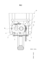
- FIG. 2 shows the main parts of a saddle-type electric vehicle 15 equipped with a drive unit 1.
- FIG. 3 shows a cross section taken along line III-III in FIG. 2.
- the letters “U,” “D,” “F,” “B,” “R,” and “L” accompanying each arrow in the figure indicate the direction of each arrow: “up,” “down,” “forward,” “backward,” “right,” and “left.”
- the shaft 4 of the motor 5 in the drive unit 1 is disposed substantially along the fore-and-aft direction of the saddle-type electric vehicle 15.
- the output shaft 11 is disposed along the left-right direction of the saddle-type electric vehicle 15.
- the central axis 16 of the shaft 4 and the central axis 18 of the output shaft 11 are approximately on the same plane (the same horizontal plane) parallel to the front-rear and left-right directions of the saddle-type electric vehicle 15. Therefore, the central axis 17 of the drive bevel gear 7 (see Figure 1) also exists on this horizontal plane.
- a roller chain 21 is stretched between the sprocket 12 of the drive unit 1 and the sprocket 20 on the rear wheel 19 side of the saddle-type electric vehicle 15.
- the rotational power transmitted to the driven bevel gear 10 is output via the sprocket 12 on the output shaft 11.
- the rotational power output from the sprocket 12 is transmitted to the rear wheel 19 of the saddle-type electric vehicle 15 via the roller chain 21 and the sprocket 20, and is used to drive the saddle-type electric vehicle 15.
- the range R2 occupied by the stator 2 and the range R1 occupied by the driven bevel gear 10 overlap at least partially at D1 in the direction along the shaft 4 of the motor 5, so the amount of protrusion P (see Figure 1) of the driven bevel gear 10 from the stator 2 in the direction along the shaft 4 can be reduced, making the drive unit 1 more compact.
- the portion of the housing 13 that covers the stator 2 can hold the base end side bearing of the driven bevel gear bearing 14 of the output shaft 11. This allows the housing 13 to have a simple configuration.
- the entire range R1 occupied by the driven bevel gear 10 is included within the range R5 occupied by the shaft 4. Therefore, even if the gear ratio is increased by increasing the number of teeth and the outer diameter of the driven bevel gear 10 relative to the driving bevel gear 7, it is possible to avoid an increase in the dimensions of the drive unit 1 in the direction along the shaft 4 of the motor 5.
- the shaft 4 of the motor 5, which is the heaviest part of the drive unit 1 is aligned in the longitudinal direction of the vehicle, so even if the motor 5 is changed to one with a shaft 4 of a different length in order to change the output of the drive unit 1, the change in the vehicle width dimension and center of gravity position of the drive unit 1 is small.
- the position of the center of gravity of the drive unit 1 changes only slightly in the vehicle width direction, moving closer to the central axis 16 of the shaft 4.
- the drive unit 1 of this embodiment is highly versatile.
- Figure 4 shows the same parts as in Figure 3 for a saddle-type electric vehicle according to a second embodiment of the present invention.
- this saddle-type electric vehicle 15b the position of the output shaft 11 of the drive unit 1b (position of the central axis 18 of the output shaft 11) is located above the position of the shaft 4 of the motor 5 (position of the central axis 16 of the shaft 4).
- the shaft 4 and the output shaft 11 are perpendicular to each other, they are in a twisted relationship with each other. Also, because the shaft 4 and the rotation axis 6 of the drive bevel gear 7 are parallel, the central axis 17 of the rotation axis 6 is also located at the same upper position as the central axis 18 of the output shaft 11 in order to ensure proper meshing between the drive bevel gear 7 and the driven bevel gear 10.
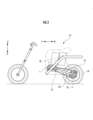
- FIG. 5 shows the main parts of a saddle-type electric vehicle according to a third embodiment of the present invention.
- this saddle-type electric vehicle 15c is a scooter-type saddle-type electric vehicle equipped with a step floor 22 on which the rider's feet rest.
- the drive unit 1c is disposed forward of the rear wheel 19.
- the drive unit 1 in the first embodiment or the drive unit 1b in the second embodiment is used as the drive unit 1c.
Landscapes
- Engineering & Computer Science (AREA)
- Power Engineering (AREA)
- Gear Transmission (AREA)
Abstract
モータのシャフトに沿った方向における寸法が小さい駆動ユニット及びこれを有する鞍乗型電動車両を提供する。駆動ユニット(1)は、モータ(5)の径方向外側に配置されてモータ(5)のシャフト(4)に沿った回転軸(6)を有する駆動ベベルギア(7)と、モータ(5)の動力を駆動ベベルギア(7)に伝達する少なくとも一対の一次ギア(8、9)と、シャフト(4)に略直交する回転軸を有して該駆動ベベルギア(7)に噛み合う被動ベベルギア(10)とを備える。この駆動ユニット(1)は、シャフト(4)に沿った方向において、モータ(5)のステータ(2)が占める範囲と被動ベベルギア(10)が占める範囲とが少なくとも一部で重なる。
Description
本発明は、駆動ユニット及びこれを有する鞍乗型電動車両に関する。
従来、鞍乗型電動車両に用いられる駆動ユニットとして、モータのシャフトが車両の前後方向に沿って配置されたモータの回転を、車両の幅方向に沿った出力軸の回転に変化させる一対のベベルギアを有するものが知られている(例えば、特許文献1参照)。
特許文献1の駆動ユニットでは、モータの回転動力が、モータのシャフトに固定されたベベルギアから、駆動ベベルギアに伝達される。駆動ベベルギアに伝達された回転動力は、駆動ベベルギアに噛み合う被動ベベルギア及び遠心クラッチを介して、駆動ユニットの出力軸に伝達される。この出力軸に伝達された動力は、スプロケット及びローラチェーンを介して、鞍乗型電動車両の後輪に伝達され、鞍乗型電動車両の走行に供される。
しかしながら、上記特許文献1の駆動ユニットによれば、モータのシャフトに沿った方向において、被動ベベルギアがモータから離れて配置されているので、該シャフトに沿った方向における駆動ユニットの寸法が大きい。また、駆動ベベルギアに対する被動ベベルギアのギア比を大きくする場合には、被動ベベルギアの外径が大きくなるので、該シャフトに沿った方向における寸法がさらに増大する。
本発明の目的は、かかる従来技術の課題に鑑み、モータのシャフトに沿った方向における寸法が小さい駆動ユニット及びこれを有する鞍乗型電動車両を提供することにある。
本発明の駆動ユニットは、ステータ及びロータを有し、該ロータのシャフトを介して動力を出力するモータと、前記モータの径方向外方において前記シャフトに沿った方向に延びる回転軸を有する駆動ベベルギアと、前記モータの動力を前記駆動ベベルギアの回転軸に伝達する少なくとも一対の一次ギアと、前記シャフトに略垂直な回転軸を有し、前記駆動ベベルギアに噛み合う被動ベベルギアとを備える。また、前記シャフトに沿った方向において、前記ステータが占める範囲と前記被動ベベルギアが占める範囲とが少なくとも一部で重なる。
本発明よれば、上記のようにステータが占める範囲と被動ベベルギアが占める範囲とが少なくとも一部で重なるので、モータのシャフトに沿った方向におけるステータからの被動ベベルギアの突出量を小さく抑え、該方向における駆動ユニットの寸法を小さくすることができる。
本発明の鞍乗型電動車両は、乗員の足を乗せるステップフロアを備えるスクータタイプの鞍乗型電動車両であって、前記本発明の駆動ユニットが、そのモータのシャフトが鞍乗型電動車両の前後方向に沿って配置されるように、該鞍乗型電動車両の後輪よりも前方に搭載される。
これによれば、本発明の駆動ユニットが、モータのシャフトが鞍乗型電動車両の前後方向に沿って配置される場合、該駆動ユニットを、上記のようにモータのシャフトに沿った方向における寸法を小さく構成できるので、駆動ユニットのステップフロアへの突出量を小さくし又は無くし、ステップフロア上に広い足元スペースを確保することができる。
以下、図面を用いて本発明の実施形態を説明する。図1は、本発明の第1実施形態に係る鞍乗型電動車両の駆動ユニットを示す。この駆動ユニット1は、ステータ2及びロータ3を有するモータ5を備える。モータ5は、ロータ3のシャフト4を介して動力を出力する。
モータ5の径方向外方には、シャフト4に沿った方向に延びる回転軸6を有する駆動ベベルギア7が配置される。モータ5のシャフト4と駆動ベベルギア7の回転軸6との間には、シャフト4の回転動力を適切に減速して駆動ベベルギア7に伝達する一対の一次ギアが設けられる。
一対の一次ギアは、モータ5のシャフト4の先端部に設けられた一次ギア8と、駆動ベベルギア7の回転軸に設けられ、歯数が一次ギア8より多い一次ギア9とで構成される。各一次ギア8、9は、ここではスパーギアで構成されるが、はすば歯車で構成してもよい。
また、駆動ユニット1は、駆動ベベルギア7と噛み合う被動ベベルギア10を備える。被動ベベルギア10の回転軸は、モータ5のシャフト4に対して略垂直であり、駆動ユニット1の出力軸11を構成する。なお、被動ベベルギア10の回転軸とモータ5のシャフト4は、本実施形態では同一平面上に存在するが、多少離れたねじれの位置にあってもよい。すなわち、「垂直」には、ねじれの位置が含まれる。
出力軸11には、ローラチェーンを介して鞍載型電動車両の車輪を回転させるスプロケット12が設けられる。モータ5のシャフト4に沿った方向において、被動ベベルギア10が占める範囲R1は、モータ5のステータ2が占める範囲R2と、少なくとも一部D1において重なる。
また、駆動ユニット1は、モータ5、一対の一次ギア8、9、駆動ベベルギア7、及び被動ベベルギア10を覆うハウジング13を備える。このハウジング13により、被動ベベルギア10の回転軸である出力軸11を支持する被動ベベルギア軸受14が保持される。被動ベベルギア軸受14は、出力軸11の基端部を支持する軸受けと、出力軸11の先端側を支持する軸受けとで構成される。
出力軸11の先端部には、鞍乗型電動車両のスプロケット12が設けられる。また、モータ5のシャフト4に沿った方向において、ステータ2が占める範囲R2内に被動ベベルギア軸受14が占める全範囲R4が含まれる。
また、モータ5のシャフト4に沿った方向において、シャフト4が占める範囲R5内に、被動ベベルギア10が占める全範囲R1が含まれる。シャフト4の中心軸線16、駆動べべルギア7の中心軸線17、及び被動ベベルギア10(出力軸11)の中心軸線18は、ほぼ同一平面上に存在する。
図2は、駆動ユニット1を搭載した鞍乗型電動車両15の主要部を示す。図3は、図2のIII-III線断面を示す。図中の各矢印に伴う「U」、「D」、「F」、「B」、「R」、「L」は、各矢印の方向が「上方」、「下方」、「前方」、「後方」、「右方」、「左方」であることを意味する。図2、図3に示すように、駆動ユニット1におけるモータ5のシャフト4は、鞍乗型電動車両15のほぼ前後方向に沿って配置される。出力軸11は、鞍乗型電動車両15の左右方向に沿って配置される。
上述のシャフト4の中心軸線16、及び出力軸11の中心軸線18は、ほぼ、鞍乗型電動車両15の前後左右方向に平行な同一平面(同じ水平面)上に存在する。したがって、駆動べべルギア7の中心軸線17(図1参照)もこの水平面上に存在する。駆動ユニット1のスプロケット12と、鞍乗型電動車両15の後輪19側のスプロケット20との間には、ローラチェーン21が掛け渡される。
この構成において、鞍乗型電動車両15の運転に際し、モータ5が駆動されると、ロータ3のシャフト4上の一次ギア8が回転する。これにより、一次ギア8と噛み合っている一次ギア9が、これと同じ回転軸6上の駆動ベベルギア7とともに減速されて回転する。この回転は、駆動ベベルギア7から、これと噛み合っている被動ベベルギア10に対して、回転軸が90度変換されつつ伝達される。
被動ベベルギア10に伝達された回転動力は、出力軸11上のスプロケット12を介して出力される。スプロケット12から出力される回転動力は、ローラチェーン21及びスプロケット20を介して、鞍乗型電動車両15の後輪19に伝達され、鞍乗型電動車両15の走行に供される。
本実施形態によれば、モータ5のシャフト4に沿った方向において、ステータ2が占める範囲R2と被動ベベルギア10が占める範囲R1とが少なくとも一部D1で重なるので、該シャフト4に沿った方向において、ステータ2からの被動ベベルギア10の突出量P(図1参照)を減少させ、駆動ユニット1のコンパクト化を図ることができる。
また、ステータ2が占める範囲内に被動ベベルギア軸受14が占める全範囲が含まれるので、ハウジング13のステータ2を覆う部分によって、出力軸11の被動ベベルギア軸受14における基端側の軸受けを保持することができる。これにより、ハウジング13を簡素な構成とすることができる。
また、シャフト4に沿った方向において、シャフト4が占める範囲R5内に被動ベベルギア10が占める全範囲R1が含まれる。このため、駆動ベベルギア7に対して被動ベベルギア10の歯数及び外径を大きくしてギア比を増大させる場合でも、これによってモータ5のシャフト4に沿った方向における駆動ユニット1の寸法が増大するのを回避することができる。
また、モータ5のシャフト4は、鞍乗型電動車両15の前後方向に沿って延在するので、シャフト4の長さが短いモータ5を採用することにより、該前後方向における駆動ユニット1の寸法をコンパクト化することができる。
また、駆動ユニット1における重量の大きい部分であるモータ5のシャフト4が車両の前後方向に沿っているので、駆動ユニット1の出力を変更するためにモータ5をシャフト4の長さが異なるものに変更する場合であっても、駆動ユニット1の車幅方向の寸法及び重心位置の変化は小さい。
例えば、駆動ユニット1を、出力を増大させるために、ロータ3の径が同じでシャフト4すなわちロータ3の長さが長いものに変更する場合、駆動ユニット1の重心位置の車幅方向の変化は、シャフト4の中心軸線16に近づく方向に、わずかに変化するだけである。
このため、モータ5の出力を変更する場合でも、駆動ユニット1の出力軸11に装着されるスプロケット12の鞍乗型電動車両15に対する位置を変える必要が無いので、鞍乗型電動車両15の本体側における後輪19側のスプロケット20などの駆動系の位置を変更する必要はない。したがって、本実施形態の駆動ユニット1は、汎用性に優れている。
図4は、本発明の第2実施形態に係る鞍乗型電動車両について図3の場合と同様の部位を示す。この鞍乗型電動車両15bでは、駆動ユニット1bの出力軸11の位置(出力軸11の中心軸線18の位置)が、モータ5のシャフト4の位置(シャフト4の中心軸線16の位置)よりも、上方に位置する。
ただし、シャフト4と出力軸11とは、相互に垂直であるため、相互にねじれの位置関係にある。また、シャフト4と駆動ベベルギア7の回転軸6とが平行であることから、駆動ベベルギア7と被動ベベルギア10との適切な噛み合いを確立するために、回転軸6の中心軸線17も、出力軸11の中心軸線18と同じ上方位置に位置する。
また、鞍乗型電動車両15bの上方から見た場合、図4に示すように、シャフト4に垂直な左右方向(車幅方向)において、ステータ2が占める範囲Aと被動ベベルギア10の回転軸(出力軸11)が占める範囲Bとが少なくとも一部Cにおいて重なる。
本実施形態によれば、鞍乗型電動車両15bの上方から見た場合、モータ5のシャフト4に垂直な方向(車幅方向)において、被動ベベルギア10(出力軸11)のステータ2からの突出量を小さく抑え、駆動ユニット1bの寸法を車幅方向においてさらに減少させることができる。
また、第1実施形態の駆動ユニット1に対して出力軸11(スプロケット12)の位置をモータ5に対して上下方向に変更する要求があった場合、本実施形態の構成を採用することにより、重いモータ5についてはその配置が維持され、比較的軽い出力軸11やスプロケット12が上方に配置されるので、極力重心位置を維持したいという鞍乗型電動車両のニーズに対応しつつ、上記要求に対応することができる。その他の点については、第1実施形態の場合と同様である。
図5は、本発明の第3実施形態に係る鞍乗型電動車両の主要部を示す。図5に示すように、この鞍乗型電動車両15cは、乗員の足を乗せるステップフロア22を備えるスクータタイプの鞍乗型電動車両である。この鞍乗型電動車両15cでは、その駆動ユニット1cは、後輪19よりも前方に配置される。
駆動ユニット1cとしては、上述の第1実施形態における駆動ユニット1や、第2実施形態における駆動ユニット1bが用いられる。
本実施形態によれば、駆動ユニット1cが、第1実施形態の駆動ユニット1や、第2実施形態の駆動ユニット1bのように、鞍乗型電動車両15cの前後方向における駆動ユニット1cの寸法をコンパクトに構成できるので、駆動ユニット1cのステップフロア22への突出量を小さくし又は無くすことができる。このため、広い足元スペースを確保することができる。その他の点については、第1実施形態や第2実施形態の場合と同様である。
以上、本発明の実施形態について説明したが、本発明はこれに限定されない。例えば、一対の一次ギア8、9に代えて、3個以上の一次ギア列を用いてもよい。また、出力軸11には、スプロケット12に代えて、プーリが設けられてもよい。なお、本発明において、鞍乗型電動車両には、スクータタイプのものや、自動二輪車も含まれる。
1、1b、1c…駆動ユニット、2…ステータ、3…ロータ、4…シャフト、5…モータ、6…回転軸、7…駆動ベベルギア、8、9…一次ギア、10、10b…被動ベベルギア、11、11b…出力軸、12…スプロケット、13…ハウジング、14…被動ベベルギア軸受、15、15b、15c…鞍乗型電動車両、16~18…中心軸線、19…後輪、20…スプロケット、21…ローラチェーン、22…ステップフロア、A…範囲、B…範囲、C、D1…一部、R1~R5…範囲。
Claims (7)
- ステータ及びロータを有し、該ロータのシャフトを介して動力を出力するモータと、
前記モータの径方向外方において前記シャフトに沿った方向に延びる回転軸を有する駆動ベベルギアと、
前記モータの動力を前記駆動ベベルギアの回転軸に伝達する少なくとも一対の一次ギアと、
前記シャフトに略垂直な回転軸を有し、前記駆動ベベルギアに噛み合う被動ベベルギアとを備え、
前記シャフトに沿った方向において、前記ステータが占める範囲と前記被動ベベルギアが占める範囲とが少なくとも一部で重なることを特徴とする駆動ユニット。 - 前記モータ、前記少なくとも一対の一次ギア、前記駆動ベベルギア、及び前記被動ベベルギアを覆うハウジングと、
前記ハウジングに保持され、前記被動ベベルギアの回転軸を支持する被動ベベルギア軸受とを備え、
前記シャフトに沿った方向において、前記ステータが占める範囲内に前記被動ベベルギア軸受が占める全範囲が含まれることを特徴とする請求項1に記載の駆動ユニット。 - 前記シャフトに沿った方向において、該シャフトが占める範囲内に前記被動ベベルギアが占める範囲が全て含まれることを特徴とする請求項1に記載の駆動ユニット。
- 鞍乗型電動車両に搭載され、前記シャフトが該鞍乗型電動車両の前後方向に沿って配置され、該鞍乗型電動車両の上方から見た場合、前記シャフトに垂直な方向において、前記ステータが占める範囲と前記被動ベベルギアの回転軸が占める範囲とが少なくとも一部で重なることを特徴とする請求項1に記載の駆動ユニット。
- 鞍乗型電動車両に搭載され、前記シャフトが該鞍乗型電動車両の前後方向に沿って配置されることを特徴とする請求項1に記載の駆動ユニット。
- 鞍乗型電動車両に搭載され、該鞍乗型電動車両のスプロケット又はプーリが前記被動ベベルギアの回転軸に設けられることを特徴とする請求項1に記載の駆動ユニット。
- 乗員の足を乗せるステップフロアを備えるスクータタイプの鞍乗型電動車両であって、該鞍乗型電動車両の後輪よりも前方に、請求項5に記載の駆動ユニットが搭載されることを特徴とする鞍乗型電動車両。
Priority Applications (1)
| Application Number | Priority Date | Filing Date | Title |
|---|---|---|---|
| PCT/JP2023/020534 WO2024247232A1 (ja) | 2023-06-01 | 2023-06-01 | 駆動ユニット及び鞍乗型電動車両 |
Applications Claiming Priority (1)
| Application Number | Priority Date | Filing Date | Title |
|---|---|---|---|
| PCT/JP2023/020534 WO2024247232A1 (ja) | 2023-06-01 | 2023-06-01 | 駆動ユニット及び鞍乗型電動車両 |
Publications (1)
| Publication Number | Publication Date |
|---|---|
| WO2024247232A1 true WO2024247232A1 (ja) | 2024-12-05 |
Family
ID=93657125
Family Applications (1)
| Application Number | Title | Priority Date | Filing Date |
|---|---|---|---|
| PCT/JP2023/020534 Ceased WO2024247232A1 (ja) | 2023-06-01 | 2023-06-01 | 駆動ユニット及び鞍乗型電動車両 |
Country Status (1)
| Country | Link |
|---|---|
| WO (1) | WO2024247232A1 (ja) |
Citations (2)
| Publication number | Priority date | Publication date | Assignee | Title |
|---|---|---|---|---|
| JP2001124153A (ja) * | 1999-10-25 | 2001-05-08 | Yamaha Motor Co Ltd | 駆動装置 |
| JP2022041209A (ja) * | 2020-08-31 | 2022-03-11 | ナブテスコ株式会社 | 減速機及び駆動装置 |
-
2023
- 2023-06-01 WO PCT/JP2023/020534 patent/WO2024247232A1/ja not_active Ceased
Patent Citations (2)
| Publication number | Priority date | Publication date | Assignee | Title |
|---|---|---|---|---|
| JP2001124153A (ja) * | 1999-10-25 | 2001-05-08 | Yamaha Motor Co Ltd | 駆動装置 |
| JP2022041209A (ja) * | 2020-08-31 | 2022-03-11 | ナブテスコ株式会社 | 減速機及び駆動装置 |
Similar Documents
| Publication | Publication Date | Title |
|---|---|---|
| JP5523636B1 (ja) | 電動アシスト自転車 | |
| JP7692159B2 (ja) | 駆動ユニットおよび電動アシスト自転車 | |
| US20110120794A1 (en) | Chain Gear, Vehicle Comprising a Chain Gear and Method for Transforming a motor Torque in a Vehicle | |
| JP6485653B2 (ja) | 電動アシスト自転車 | |
| JP2005289283A (ja) | 自転車用駆動ユニット | |
| JP7390592B2 (ja) | モータユニット及び電動自転車 | |
| JP7199219B2 (ja) | ハブ | |
| CN110785344A (zh) | 具有包括功率分流的电驱动器的自行车 | |
| JP7617538B2 (ja) | モータユニット | |
| CN106604863A (zh) | 电动助力自行车 | |
| JP2024149620A (ja) | モータユニット及び電動自転車 | |
| JP2023133532A (ja) | モータユニット及び電動自転車 | |
| JP6391034B2 (ja) | モータ駆動ユニット及び電動アシスト自転車 | |
| JP6548103B2 (ja) | モータ駆動ユニット及び電動アシスト自転車 | |
| JP6956464B2 (ja) | インホイールモータ駆動装置 | |
| CN114929570A (zh) | 带侧装车轮的前电机驱动自行车 | |
| JP7233002B2 (ja) | モータユニット及び電動自転車 | |
| WO2020194951A1 (ja) | 鞍乗型電動車両 | |
| JP2008224020A (ja) | 三輪車の差動装置 | |
| JP2013139242A (ja) | 電動補助人力車両用ハブユニットおよび電動補助人力車両 | |
| JP7821988B2 (ja) | モータユニット及び電動自転車 | |
| JP7810123B2 (ja) | 自動車に搭載されるインホイールモータ駆動装置 | |
| JP6519831B2 (ja) | モータ駆動ユニット及び電動アシスト自転車 | |
| JP6519832B2 (ja) | モータ駆動ユニット及び電動アシスト自転車 | |
| JP6384819B2 (ja) | モータ駆動ユニット及び電動アシスト自転車 |
Legal Events
| Date | Code | Title | Description |
|---|---|---|---|
| 121 | Ep: the epo has been informed by wipo that ep was designated in this application |
Ref document number: 23939706 Country of ref document: EP Kind code of ref document: A1 |
|
| NENP | Non-entry into the national phase |
Ref country code: DE |
|
| 122 | Ep: pct application non-entry in european phase |
Ref document number: 23939706 Country of ref document: EP Kind code of ref document: A1 |
|
| NENP | Non-entry into the national phase |
Ref country code: JP |