WO2024241585A1 - 音響装置、プログラム、および制御方法 - Google Patents
音響装置、プログラム、および制御方法 Download PDFInfo
- Publication number
- WO2024241585A1 WO2024241585A1 PCT/JP2023/019548 JP2023019548W WO2024241585A1 WO 2024241585 A1 WO2024241585 A1 WO 2024241585A1 JP 2023019548 W JP2023019548 W JP 2023019548W WO 2024241585 A1 WO2024241585 A1 WO 2024241585A1
- Authority
- WO
- WIPO (PCT)
- Prior art keywords
- volume
- audio data
- unit
- display
- synthesis
- Prior art date
- Legal status (The legal status is an assumption and is not a legal conclusion. Google has not performed a legal analysis and makes no representation as to the accuracy of the status listed.)
- Ceased
Links
Images


Classifications
-
- G—PHYSICS
- G10—MUSICAL INSTRUMENTS; ACOUSTICS
- G10H—ELECTROPHONIC MUSICAL INSTRUMENTS; INSTRUMENTS IN WHICH THE TONES ARE GENERATED BY ELECTROMECHANICAL MEANS OR ELECTRONIC GENERATORS, OR IN WHICH THE TONES ARE SYNTHESISED FROM A DATA STORE
- G10H1/00—Details of electrophonic musical instruments
- G10H1/46—Volume control
-
- H—ELECTRICITY
- H04—ELECTRIC COMMUNICATION TECHNIQUE
- H04R—LOUDSPEAKERS, MICROPHONES, GRAMOPHONE PICK-UPS OR LIKE ACOUSTIC ELECTROMECHANICAL TRANSDUCERS; ELECTRIC HEARING AIDS; PUBLIC ADDRESS SYSTEMS
- H04R3/00—Circuits for transducers
Definitions
- the present invention relates to an audio device, a program, and a control method.
- Non-Patent Document 1 performs a mixing process to synthesize audio data input to four channels.
- DJM-900NXS2 User Manual (https://www.pioneerdj.com/ja-jp/support/documents/archive/ddj-sz/#manual)
- the present invention aims to provide an audio device, program, and control method that allows users to easily grasp various information in an audio device that synthesizes and outputs two or more pieces of audio data.
- the audio signal processing device is an audio device that synthesizes and outputs two or more pieces of audio data, and includes a synthesis unit that synthesizes the two or more pieces of audio data, and a display control unit that displays on a display a screen on which two or more first indicators indicating the volume of each of the two or more pieces of audio data and a second indicator indicating the volume of the audio data after synthesis by the synthesis unit are arranged in a common coordinate system.
- the program according to the present invention is configured to cause a computer to function as the audio device described above.
- the control method according to the present invention is a control method implemented by an audio device that synthesizes and outputs two or more pieces of audio data, and includes the steps of synthesizing two or more pieces of audio data, and displaying on a display a screen on which two or more first indicators indicating the volume of each of the two or more pieces of audio data and a second indicator indicating the volume of the audio data after synthesis in the synthesis step are arranged in a common coordinate system.
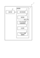
- FIG. 1 is a schematic diagram showing a DJ mixer according to a first embodiment of the present invention.
- FIG. 2 is a block diagram showing the functional configuration of a control unit of the DJ mixer 1 according to the first embodiment of the present invention.
- FIG. 2 is a diagram showing a process flow in each unit according to the first embodiment of the present invention.
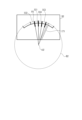
- FIG. 4 is a diagram showing an example of a display screen displayed on a display unit in the first embodiment of the present invention.
- FIG. 4 is another diagram showing an example of a display screen displayed on the display unit in the first embodiment of the present invention.
- FIG. 4 is another diagram showing an example of a display screen displayed on the display unit in the first embodiment of the present invention.
- FIG. 4 is another diagram showing an example of a display screen displayed on the display unit in the first embodiment of the present invention.
- FIG. 4 is another diagram showing an example of a display screen displayed on the display unit in the first embodiment of the present invention.
- FIG. 4 is another diagram showing an example of a display screen displayed on the display unit in the first embodiment of the present invention.
- 5 is a flowchart showing an operation of a control unit according to the first embodiment of the present invention.
- FIG. 11 is a diagram showing a process flow in each unit according to the second embodiment of the present invention.
- 10 is a flowchart showing an operation of a control unit according to a second embodiment of the present invention.
- FIG. 1 shows a schematic diagram of a DJ mixer 1, which is an audio device according to a first embodiment of the present invention.
- a DJ mixer 1 is an audio device according to a first embodiment of the present invention.
- an analog player, a CD player, a music playback device that plays music data such as a computer, and a music operation device such as a DJ controller are connected to the input side of the DJ mixer 1.
- an audio device such as a speaker is connected to the output side of the DJ mixer 1.
- the DJ mixer 1 includes a microphone adjustment section 2, an effects processing section 3, a master adjustment section 4, and an equalizer adjustment section 5.
- the microphone adjustment unit 2 includes controls for adjusting the output volume of a microphone (not shown) connected to the DJ mixer 1 and for starting and stopping effect processing by the effect processing unit 3.
- the microphone adjustment unit 2 also includes a terminal through which the user can connect headphones to monitor the output volume of the audio data output from the DJ mixer 1.
- the microphone adjustment unit 2 includes, for example, a headphone input/output terminal, a headphone volume adjustment unit, a mixing adjustment unit, a master effect switching and effect amount adjustment unit, a microphone switching unit and volume adjustment unit, a microphone equalizer adjustment unit, etc.
- the effect processing section 3 includes operators for performing effect processing such as adding sound effects or special effects to the input audio data.
- the effect processing section 3 also includes an effect processing section, an effect switching section, a channel switching section, an effect time setting section, an effect amount adjustment section, etc.
- the master adjustment unit 4 includes controls for applying effects to the sound output from the DJ mixer 1 and adjusting the overall amplified audio data.
- the master adjustment unit 4 includes a display unit 41 and a master volume adjustment unit 42.
- the display unit 41 has a display 41A, which displays information about the master volume and the volume for each channel, allowing the user to visually confirm the information.
- Various types of display devices can be used as the display 41A, such as a liquid crystal display device or an organic EL display device.
- the master volume adjustment section 42 includes an operating knob 42A, which is an operator that adjusts the overall output volume of the audio data output from the DJ mixer 1.
- the equalizer adjustment unit 5 includes operators for performing equalizer processing for each channel on audio data input from a music playback device connected to the DJ mixer 1. Specifically, the equalizer adjustment unit 5 includes a first adjustment unit 5A to a fourth adjustment unit 5D that adjust four channels, CH1, CH2, CH3, and CH4. A music playback device and a music operation device are connected to the first adjustment unit 5A to the fourth adjustment unit 5D, respectively, and equalizer adjustment can be performed for each of the first adjustment unit 5A to the fourth adjustment unit 5D.
- Each of the first adjustment unit 5A to the fourth adjustment unit 5D includes an input switching unit 51A to 51D, an input channel volume adjustment unit 52A to 52D, a band volume adjustment unit 53A to 53D, an effect adjustment unit 54A to 54D, and a channel volume adjustment unit 55A to 55D.
- the equalizer adjustment unit 5 also includes a crossfader 57.
- the input switching units 51A to 51D include operators that switch the input sources of the music playback device and music operation device connected to the DJ mixer 1.
- the input switching units 51A to 51D switch between connected devices, such as an analog player connected to the phono terminal of the DJ mixer 1, a CD player connected to the line terminal, and a computer connected to the USB terminal.
- the input channel volume adjustment sections 52A to 52D include operators for adjusting the input volume of the connected device selected by the input switching sections 51A to 51D.
- the band-specific volume adjustment units 53A to 53D include controls that adjust the volume by amplifying or attenuating the input audio data for each of multiple frequency bands.
- the effect adjustment sections 54A to 54D include operators for adjusting the amount of effect applied and the depth of the effect set in the first adjustment section 5A to the fourth adjustment section 5D, respectively, that is, the degree of effect processing.
- the channel volume adjustment units 55A to 55D each include a channel fader 56A to 56D which is an operator for adjusting the volume output from the first adjustment unit 5A to the fourth adjustment unit 5D, respectively.
- FIG. 2 is a block diagram showing the functional configuration of the control unit of the DJ mixer 1 according to the first embodiment of the present invention.
- the control unit 7 includes a display control unit 71, an acquisition unit 72, and a synthesis unit 73 in addition to the channel volume adjustment units 55A to 55D and the master volume adjustment unit 42 shown in Fig. 1.
- the functions of each unit are realized by a processor operating according to a program in an audio device having the hardware configuration of a computer, for example.
- the display control unit 71 causes a screen including information on the master volume and the volume for each channel to be displayed on the display unit 41. Details of the display screen displayed on the display unit 41 will be described later.
- the acquisition unit 72 acquires audio data and outputs from various controls of the DJ mixer 1 .
- the synthesis unit 73 synthesizes the audio data input to channels CH1, CH2, CH3, and CH4 of the DJ mixer 1.
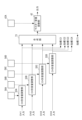
- FIG. 3 shows a diagram illustrating the flow of processing in each section.
- audio data input to channel CH1 is input to a channel volume control unit 55A.
- audio data input to channel CH2 is input to a channel volume control unit 55B
- audio data input to channel CH3 is input to a channel volume control unit 55C
- audio data input to channel CH4 is input to a channel volume control unit 55D.
- the channel-specific volume adjustment unit 55A adjusts the volume of the input audio data in response to user operation on the channel fader 56A and outputs the adjusted volume to the synthesis unit 73.
- the channel-specific volume adjustment unit 55B adjusts the volume of the input audio data in response to user operation on the channel fader 56B and outputs the adjusted volume to the synthesis unit 73
- the channel-specific volume adjustment unit 55C adjusts the volume of the input audio data in response to user operation on the channel fader 56C and outputs the adjusted volume to the synthesis unit 73
- the channel-specific volume adjustment unit 55D adjusts the volume of the input audio data in response to user operation on the channel fader 56D and outputs the adjusted volume to the synthesis unit 73.
- the synthesis unit 73 synthesizes the audio data output by each of the channel volume adjustment units 55A to 55D, and outputs the synthesized data to the master volume adjustment unit .
- the master volume adjustment unit 42 adjusts the volume of the audio data input from the synthesis unit 73 in response to a user's operation on the operation knob 42A, and outputs the adjusted volume.
- Example of display screen 4 to 8 are diagrams showing examples of display screens displayed on the display unit 41 in this embodiment.
- the display control unit 71 causes the display 41A of the display unit 41 to display any one of the display screens shown in Figs. 4 to 8.
- the display screen D1 displays first indices IC1, IC2, IC3, and IC4, and a second index IT1.
- the first indices IC1, IC2, IC3, and IC4 are indices that indicate the volume of the output of channels CH1, CH2, CH3, and CH4, respectively
- the second index IT1 is an index that indicates the volume of the audio data after synthesis by the synthesis unit 73.
- the first indices IC1, IC2, IC3, and IC4 and the second index IT1 are arranged in a common coordinate system. Also, in the display screen D1, each index is displayed based on a line segment whose two ends are the center point O1 of the reference circle B1 and a point on the arc of the reference circle B1. For example, the first index IC1 is displayed by a line segment whose two ends are the center point O1 and a point P1 on the arc. The same is true for the first indexes IC2, IC3, IC4, and the second index IT1.
- the volume is displayed based on the angle formed by two line segments among the first index IC1, IC2, IC3, IC4, and the second index IT.
- the angle formed by the line segment indicating the first index IC1 and the line segment indicating the second index IT1 corresponds to the difference between the volume of the output of channel CH1 and the volume of the audio data after synthesis by the synthesis unit 73. The same applies to the other combinations.
- the display control unit 71 determines a first index IC1 based on the volume of the audio data output from the channel volume adjustment unit 55A and input to the synthesis unit 73. Similarly, the display control unit 71 determines a first index IC2 based on the volume of the audio data output from the channel volume adjustment unit 55B and input to the synthesis unit 73, determines a first index IC3 based on the volume of the audio data output from the channel volume adjustment unit 55C and input to the synthesis unit 73, and determines a first index IC4 based on the volume of the audio data output from the channel volume adjustment unit 55D and input to the synthesis unit 73. As shown in FIG. 3, the display control unit 71 also determines a second index IT1 based on the volume of the audio data output from the synthesis unit 73 and input to the master volume adjustment unit 42.
- the display control unit 71 may display the first indicators IC1, IC2, IC3, and IC4 and the second indicator IT in different display forms.
- Examples of display forms include the type of display color, the shade of the display color, color display and monochrome display, the type of background color, the shade of the background color, the presence or absence of a background color, a blinking pattern, blinking and non-blinking, etc.
- the display control unit 71 may also display the first indicators IC1, IC2, IC3, and IC4 in different display forms.
- the display forms are as described above.
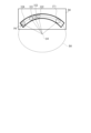
- FIG. 5 shows a modified example of the display screen D1 shown in FIG. 4.
- the display screen D2 displays the first indices IC1, IC2, IC3, and IC4, and the second index IT1.
- the first indexes IC1, IC2, IC3, and IC4 and the second index IT1 are arranged in a common coordinate system.
- each index is displayed based on a line segment having both ends at the center point O2 of the reference circle B2 and a point P on the arc of the reference circle B2.
- the first index IC2 is displayed based on a line segment having both ends at the center point O2 and a point P2 on the arc.
- the first indexes IC1, IC3, IC4, and the second index IT1 may be outside the display screen D2.
- FIG. 6 shows another modified example of the display screen D1 shown in FIG. 4.
- the display screen D3 displays the first indices IC1, IC2, IC3, and IC4, and the second index IT1.
- the first indexes IC1, IC2, IC3, and IC4 and the second index IT1 are arranged in a common coordinate system.
- each index is displayed based on a line segment having both ends at the center point O3 of the reference circle B3 and a point P on the arc of the reference circle B3.
- the first index IC3 is displayed based on a line segment having both ends at the center point O3 and a point P3 on the arc.
- each index may be displayed in a shape other than a line segment.
- FIG. 7 shows another modified example of the display screen D1 shown in FIG. 4.
- the display screen D4 displays the first indices IC1, IC2, IC3, and IC4, and the second index IT1.
- the first indices IC1, IC2, IC3, and IC4 and the second index IT1 are arranged in a common coordinate system.
- each index is displayed based on a line segment having both ends at the center point O4 of the reference circle B4 and a point P on the arc of the reference circle B4.
- the first index IC4 is displayed based on a line segment having both ends at the center point O4 and a point P4 on the arc.
- the reference circle B4 is not limited to a perfect circle, and may be an ellipse.
- the first indexes IC1, IC2, IC3, IC4, and the second index IT1 may include text or marks indicating the type of channel, etc.
- FIG. 8 shows another modified example of the display screen D1 shown in FIG. 4.
- the display screen D5 displays the first indices IC1, IC2, IC3, and IC4, and the second index IT1.
- the first indices IC1, IC2, IC3, and IC4 and the second indices IT1 are arranged in a common coordinate system.
- each indices is displayed in a line shape, and each indices is displayed by an icon having a different shape, and the volume is displayed based on the distance between the two icons.
- display screen D5 does not have a reference circle or a center point, but since a reference circle with an infinite radius can be approximated by a straight line, the angle formed by two or more line segments similar to those of display screens D1 to D4 can also be approximated by the above-mentioned distance on display screen D5.
- first indices IC1, IC2, IC3, and IC4 indicating the output volume of the four channels CH1, CH2, CH3, and CH4, and a second index IT1 indicating the volume of the audio data after synthesis by the synthesis unit 73 are displayed in one coordinate system on one screen.
- the first indexes IC1, IC2, IC3, and IC4 change in accordance with changes in the output volumes of the four channels CH1, CH2, CH3, and CH4, respectively. Furthermore, the second index IT1 also changes in accordance with changes in the output volumes of the four channels CH1, CH2, CH3, and CH4. On the other hand, even if the volume of the audio data input from the synthesis unit 73 is adjusted by the master volume adjustment unit 42 by operating the operation knob 42A, the second index IT1 does not change.
- the user can therefore understand the change in volume before and after the mix process by comparing and checking the first indicators IC1, IC2, IC3, and IC4 with the second indicator IT1. Therefore, the user can easily determine, for example, how to operate the operation knob 42A of the master volume adjustment unit 42 during the mix process.
- the user can grasp the difference in volume between the channels. Therefore, when switching songs during mix processing, the user can easily determine, for example, which channel has the louder volume. This effect is particularly useful when performing a so-called long mix, in which the speed of songs is aligned and the songs are switched slowly.
- Figures 4 to 8 are examples of display screens, and the present invention is not limited to these examples. In addition, some or all of the features and elements described for each display screen may be combined.
- FIG. 9 is a flowchart showing a control method executed by the control unit 7.
- the control unit 7 detects the volume of the audio data output by each channel volume adjustment unit 55A to 55D (step S101), the synthesis unit 73 synthesizes the audio data output by the channel volume adjustment units 55A to 55D (step S102), and the control unit 7 detects the volume of the audio data output from the synthesis unit 73 (step S103).
- the display control unit 71 determines the first indexes IC1, IC2, IC3, IC4 and the second index IT1 based on the detection results of steps S101 and S103 (step S104), and causes the display 41A to display a display screen (step S105).
- the control unit 7 repeats steps S101 to S105 at a predetermined time interval. Therefore, the display screen displayed on the display 41A can be updated in real time.
- the DJ mixer 1 is an audio device that synthesizes and outputs two or more pieces of audio data, and is equipped with a synthesis unit 73 that synthesizes two or more pieces of audio data, and a display control unit 71 that displays on the display 41A a screen (D1 to D5) in which two or more first indicators IC1, IC2, IC3, and IC4 indicating the volume of each of the two or more pieces of audio data, and a second indicator IT1 indicating the volume of the audio data after synthesis by the synthesis unit 73 are arranged in a common coordinate system.
- the display control unit 71 displays the first indexes IC1, IC2, IC3, and IC4 and the second index IT1 based on line segments whose ends are the center point (O1 or O4) of the reference circle (B1 to B4) and a point on the arc of the reference circle, and displays the respective volumes based on the angle formed by two or more line segments. This makes it easy to check the first indexes IC1, IC2, IC3, and IC4 and the second index IT1 while comparing them, allowing the user to intuitively and easily grasp information about the mix process.
- the display control unit 71 displays the first indices IC1, IC2, IC3, and IC4 and the second indices in different display forms. Therefore, the user can intuitively and easily distinguish between the first indices IC1, IC2, IC3, and IC4 and the second indices.
- the display control unit displays the first indices IC1, IC2, IC3, and IC4 in different display forms. Therefore, the user can intuitively and easily distinguish the first indices IC1, IC2, IC3, and IC4.
- Second Embodiment In the second embodiment, only the parts that are different from the first embodiment will be described, and the description of the parts that are the same as those in the first embodiment will be omitted.
- the DJ mixer according to the second embodiment includes a post-processing unit 74 shown in FIG. 10 in addition to the components of the DJ mixer 1 according to the first embodiment.
- the post-processing unit 74 performs post-processing, such as compression processing and transformer processing, on the audio data input from the synthesis unit 73.
- FIG. 10 corresponds to FIG. 3 of the first embodiment, and shows a diagram illustrating the flow of processing in each unit. As shown in FIG. 10, the processing in the channel volume adjustment units 55A to 55D is similar to that in the first embodiment.
- the synthesis unit 73 synthesizes the audio data output by each of the channel volume adjustment units 55A to 55D, and outputs the synthesized data to the post-processing unit 74.
- the post-processing unit 74 performs post-processing on the audio data input from the synthesis unit 73 and outputs the result to the master volume adjustment unit 42 .
- the master volume adjustment unit 42 adjusts the volume of the audio data input from the post-processing unit 74 in response to a user operation on the operation knob 42A, and outputs the adjusted volume.
- the display control unit 71 determines the first indices IC1, IC2, IC3, and IC4 in the same manner as in the first embodiment. On the other hand, unlike the first embodiment, the display control unit 71 determines the second index IT1 based on the volume of the audio data output from the post-processing unit 74 and input to the master volume adjustment unit 42.
- the post-processing unit 74 processes such as compressor processing and transformer processing are performed. Therefore, there may be a difference between the volume of the audio data input from the synthesis unit 73 to the post-processing unit 74 and the volume of the audio data output from the post-processing unit 74. More specifically, the volume of the audio data output from the post-processing unit 74 may be smaller than the volume of the audio data input to the post-processing unit 74. In such a case, the first indexes IC1, IC2, IC3, and IC4 are based on different standards from the second index, resulting in a problem that the display may be inaccurate for the user.
- the display control unit 71 adjusts and displays the first indicators IC1, IC2, IC3, and IC4 based on a correction value according to a change in volume by the post-processing unit 74. For example, when the volume of the audio data output from the post-processing unit 74 is 10% lower than the volume of the audio data input to the post-processing unit 74, the display control unit 71 adjusts and displays the first indicators IC1, IC2, IC3, and IC4 using ⁇ 10% as a correction value. In this way, by adjusting the first indicators IC1, IC2, IC3, and IC4 based on the correction value according to the change in volume by the post-processing unit 74, the above-mentioned problem can be reduced.
- FIG. 11 is a flowchart showing a control method executed by the control unit 7.
- the control unit 7 detects the volume of the audio data output by each channel volume adjustment unit 55A to 55D (step S201), the synthesis unit 73 synthesizes the audio data output by the channel volume adjustment units 55A to 55D (step S202), and the control unit 7 detects the volume of the audio data output from the synthesis unit 73 (step S203).
- the post-processing unit 74 performs post-processing on the audio data output from the synthesis unit 73 (step S204), and the control unit 7 detects the volume of the audio data output from the post-processing unit 74 (step S205). Then, the display control unit 71 calculates a correction value based on the detection results of steps S203 and S205 (step S206).
- the display control unit 71 determines the first indexes IC1, IC2, IC3, IC4, and the second index IT1 based on the detection results of steps S201 and S205 (step S207). Furthermore, the display control unit 71 adjusts the first indexes IC1, IC2, IC3, and IC4 based on the correction value calculated in step S206 (step S208), and causes the display 41A to display a display screen (step S209).
- the control unit 7 repeats steps S201 to S209 at a predetermined time interval, thereby updating the display screen displayed on the display 41A in real time.
- the detection of the volume of the audio data output from the synthesis unit 73 described in step S203 and the calculation of the correction value described in step S206 can be omitted, and in step S208, the first indexes IC1, IC2, IC3, and IC4 can be adjusted based on the known correction value.
- a post-processing unit 74 which performs post-processing on the audio data synthesized by the synthesis unit 73, and the display control unit 71 adjusts and displays the first indicator based on a correction value corresponding to a change in volume by the post-processing unit 74.
- a screen is displayed in which an indicator showing the volume of the audio data output from band-specific volume adjustment units 53A to 53D and an indicator showing the volume of the audio data after combining these audio data are arranged in a common coordinate system.
- the present invention may be similarly applied to various effect processes.
- a screen is displayed in which an indicator showing the volume of audio data input to an arbitrary effect processing unit and an indicator showing the volume of audio data output from the effect processing unit are arranged in a common coordinate system.
- audio devices with the above functions are not limited to the examples described in the above embodiments, and similar functions can be implemented in other DJ equipment, such as DJ controllers with mixer functions and all-in-one DJ systems (digital audio players with communication and mixing functions).
- DJ controllers with mixer functions and all-in-one DJ systems digital audio players with communication and mixing functions.
- the present invention may also be applied to computers, smartphones, and tablet terminals that run DJ applications.
- the present invention may be applied not only to DJ equipment and DJ applications, but also to music applications, streaming services using the Internet, etc. In such cases, the present invention can be applied to automatic playback using playlists, etc.
- a four-channel audio device has been described in each of the above embodiments, the same functions can be realized with, for example, a two-channel audio device.
- the present invention is not limited to DJ equipment, and can also be applied to audio devices such as general mixers and electronic musical instruments, as well as DAWs (Digital Audio Workstations) and DTMs (Desk Top Music).
- An audio device that synthesizes and outputs two or more pieces of audio data, comprising: a synthesis unit that synthesizes the two or more pieces of audio data; and a display control unit that displays on a display a screen on which two or more first indicators indicating the volume of each of the two or more pieces of audio data and a second indicator indicating the volume of the audio data after synthesis by the synthesis unit are arranged in a common coordinate system.
- the display control unit of the audio device described in [1] is characterized in that the first indicator and the second indicator are displayed based on a line segment having a center point of the reference circle and a point on the arc of the reference circle as both ends, and the volume is displayed based on the angle formed by two or more line segments.
- a program configured to cause a computer to function as the audio device according to any one of [1] to [5].
- a control method implemented by an audio device that synthesizes and outputs two or more pieces of audio data including: a step of synthesizing two or more pieces of audio data; and a step of displaying on a display a screen on which two or more first indicators indicating the volume of each of the two or more pieces of audio data and a second indicator indicating the volume of the audio data after synthesis in the synthesis step are arranged in a common coordinate system.
Landscapes
- Physics & Mathematics (AREA)
- Engineering & Computer Science (AREA)
- Acoustics & Sound (AREA)
- Signal Processing (AREA)
- Multimedia (AREA)
- Circuit For Audible Band Transducer (AREA)
Priority Applications (2)
| Application Number | Priority Date | Filing Date | Title |
|---|---|---|---|
| JP2025521770A JPWO2024241585A1 (https=) | 2023-05-25 | 2023-05-25 | |
| PCT/JP2023/019548 WO2024241585A1 (ja) | 2023-05-25 | 2023-05-25 | 音響装置、プログラム、および制御方法 |
Applications Claiming Priority (1)
| Application Number | Priority Date | Filing Date | Title |
|---|---|---|---|
| PCT/JP2023/019548 WO2024241585A1 (ja) | 2023-05-25 | 2023-05-25 | 音響装置、プログラム、および制御方法 |
Publications (1)
| Publication Number | Publication Date |
|---|---|
| WO2024241585A1 true WO2024241585A1 (ja) | 2024-11-28 |
Family
ID=93589284
Family Applications (1)
| Application Number | Title | Priority Date | Filing Date |
|---|---|---|---|
| PCT/JP2023/019548 Ceased WO2024241585A1 (ja) | 2023-05-25 | 2023-05-25 | 音響装置、プログラム、および制御方法 |
Country Status (2)
| Country | Link |
|---|---|
| JP (1) | JPWO2024241585A1 (https=) |
| WO (1) | WO2024241585A1 (https=) |
Citations (3)
| Publication number | Priority date | Publication date | Assignee | Title |
|---|---|---|---|---|
| JPH10288989A (ja) * | 1997-04-15 | 1998-10-27 | Roland Corp | 電子楽器 |
| JP2012054857A (ja) * | 2010-09-03 | 2012-03-15 | Sony Corp | 制御端末装置、制御方法 |
| JP2013123154A (ja) * | 2011-12-12 | 2013-06-20 | Onkyo Corp | 音量制御システム、音量制御システムのコントローラのプログラム、及び音量制御システムの音声出力装置 |
-
2023
- 2023-05-25 JP JP2025521770A patent/JPWO2024241585A1/ja active Pending
- 2023-05-25 WO PCT/JP2023/019548 patent/WO2024241585A1/ja not_active Ceased
Patent Citations (3)
| Publication number | Priority date | Publication date | Assignee | Title |
|---|---|---|---|---|
| JPH10288989A (ja) * | 1997-04-15 | 1998-10-27 | Roland Corp | 電子楽器 |
| JP2012054857A (ja) * | 2010-09-03 | 2012-03-15 | Sony Corp | 制御端末装置、制御方法 |
| JP2013123154A (ja) * | 2011-12-12 | 2013-06-20 | Onkyo Corp | 音量制御システム、音量制御システムのコントローラのプログラム、及び音量制御システムの音声出力装置 |
Also Published As
| Publication number | Publication date |
|---|---|
| JPWO2024241585A1 (https=) | 2024-11-28 |
Similar Documents
| Publication | Publication Date | Title |
|---|---|---|
| JP6086188B2 (ja) | 音響効果調整装置および方法、並びにプログラム | |
| JP5400225B2 (ja) | オーディオ信号の空間的抽出のためのシステム | |
| US8073160B1 (en) | Adjusting audio properties and controls of an audio mixer | |
| US20040030425A1 (en) | Live performance audio mixing system with simplified user interface | |
| CN103262573B (zh) | 声音再生装置、再生音调整方法、音响特性调整装置、音响特性调整方法及计算机程序 | |
| WO2023284593A1 (zh) | 耳机及耳机音效的调节方法 | |
| JP2012209766A (ja) | コントローラー | |
| WO2008033450A2 (en) | Signal path using general-purpose computer for audio processing and audio-driven graphics | |
| WO2024241585A1 (ja) | 音響装置、プログラム、および制御方法 | |
| US10158439B2 (en) | Level control apparatus and storage medium | |
| JP7388061B2 (ja) | 音信号処理方法、音信号処理システム、およびプログラム | |
| US9712268B2 (en) | Level control apparatus and storage medium | |
| JP2004318075A (ja) | 音楽再生装置 | |
| JPH1084241A (ja) | 音響信号処理装置 | |
| US10270551B2 (en) | Mixing console with solo output | |
| US11102606B1 (en) | Video component in 3D audio | |
| WO2024241583A1 (ja) | 音響装置、音響装置の制御方法、及びプログラム | |
| JP5633140B2 (ja) | 音響パラメータの制御装置 | |
| US10083680B2 (en) | Mixing console | |
| WO2025134280A1 (ja) | 音響装置、音響装置の制御方法およびプログラム | |
| JP2015186046A (ja) | 信号処理装置およびプログラム | |
| Midas et al. | Products of Interest | |
| JPH10261928A (ja) | グラフィックイコライザ装置およびその調整方法 | |
| JPH07321574A (ja) | 音量および音量比の表示/調整方法 | |
| JP6484066B2 (ja) | オーディオ装置 |
Legal Events
| Date | Code | Title | Description |
|---|---|---|---|
| 121 | Ep: the epo has been informed by wipo that ep was designated in this application |
Ref document number: 23938547 Country of ref document: EP Kind code of ref document: A1 |
|
| ENP | Entry into the national phase |
Ref document number: 2025521770 Country of ref document: JP Kind code of ref document: A |
|
| NENP | Non-entry into the national phase |
Ref country code: DE |