WO2024241360A1 - アクチュエータおよびロボット - Google Patents
アクチュエータおよびロボット Download PDFInfo
- Publication number
- WO2024241360A1 WO2024241360A1 PCT/JP2023/018725 JP2023018725W WO2024241360A1 WO 2024241360 A1 WO2024241360 A1 WO 2024241360A1 JP 2023018725 W JP2023018725 W JP 2023018725W WO 2024241360 A1 WO2024241360 A1 WO 2024241360A1
- Authority
- WO
- WIPO (PCT)
- Prior art keywords
- pair
- filaments
- wires
- actuator
- filament
- Prior art date
- Legal status (The legal status is an assumption and is not a legal conclusion. Google has not performed a legal analysis and makes no representation as to the accuracy of the status listed.)
- Ceased
Links
Images


Classifications
-
- B—PERFORMING OPERATIONS; TRANSPORTING
- B25—HAND TOOLS; PORTABLE POWER-DRIVEN TOOLS; MANIPULATORS
- B25J—MANIPULATORS; CHAMBERS PROVIDED WITH MANIPULATION DEVICES
- B25J19/00—Accessories fitted to manipulators, e.g. for monitoring, for viewing; Safety devices combined with or specially adapted for use in connection with manipulators
Definitions
- This disclosure relates to actuators and robots.
- Industrial robots particularly articulated robots, include at least one joint where two links are connected to each other.
- the joint is provided with an actuator that drives the link, and at least a power line is required to drive the actuator.
- signal lines, air tubes, coaxial cables, high-speed communication signal lines, etc. are required to drive the end effector and sensors provided at the tip of the industrial robot.
- these power lines, air tubes, coaxial cables, and various signal lines may be collectively referred to as "lines.”
- the actuator has a fixed member and a movable member that rotate relative to each other.
- a wire passes through the inside of the actuator, and the wire is fixed to the fixed member and the movable member by a first fixed portion and a second fixed portion, respectively.
- the wire may contain a twisted pair of wires, in which a pair of conductors covered with insulation are twisted together to make the wire less susceptible to the effects of noise.
- a robot When a robot is operated and the diameter of the conductors that make up a twisted pair, such as a power line, is large, the insulation around the conductors expands and contracts more, which may cause the insulation to break earlier than expected. In the area where the insulation breaks, the stress acting on the wire acts directly on the conductor, and as a result, it is only a matter of time before the conductor breaks.
- an actuator comprising a fixed member, a movable member that rotates relative to the fixed member, a hollow hole that passes through the actuator, a wire that passes through the hollow hole, a first fixing portion that fixes a portion of the wire, and a second fixing portion that fixes another portion of the wire, the wire including at least a pair of first wires having a first diameter and a pair of second wires having a second diameter smaller than the first diameter, each of the pair of first wires being a solid wire, and the pair of second wires being a twisted pair.
- FIG. 1 is a perspective view of a robot equipped with an actuator based on a first embodiment.
- FIG. 2 is an axial cross-sectional view of the actuator according to the first embodiment.
- FIG. 2 is a partial enlarged view of a filament according to the first embodiment.
- FIG. 11 is a partial enlarged view of a filament according to a second embodiment.
- FIG. 11 is an axial cross-sectional view of an actuator according to a first modified example.
- FIG. 11 is an axial cross-sectional view of an actuator according to a second modified example.
- FIG. 2 is a radial cross-sectional view of a filament in one example.
- FIG. 11 is a radial cross-sectional view of a filament according to another example.
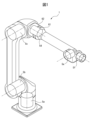
- Fig. 1 is a perspective view of a robot equipped with actuators according to a first embodiment.
- Each of a plurality of joints of a robot is equipped with actuators 5a to 5f.
- the actuators 5a to 5f may be incorporated in a machine other than the robot 1, for example a machine tool.
- the actuator 5 will be described below, but the actuators 5a to 5f shown in Fig. 1 are also assumed to have a similar configuration.
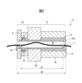
- FIG. 2 is an axial cross-sectional view of an actuator based on the first embodiment.
- the actuator 5 is mainly composed of a fixed member 21 and a movable member 22 that rotates relative to the fixed member 21.
- the fixed member 21 includes a motor 10, such as a servo motor, that is composed of a stator and a rotor, and a reducer 20 connected to the motor shaft 13 of the motor 10.
- the movable member 22 includes an output shaft 23 of the reducer 20 and a force sensor S coupled to the output shaft 23.
- the movable member 22 may be configured to include only the output shaft 23 of the reducer 20.
- the reducer 20 is defined as being disposed in front of the motor 10, and the motor 10 is defined as being disposed behind the reducer 20.
- the "radial direction” in this application means the radial direction of the actuator 5, etc.
- the "axial direction” means the axial direction of the actuator 5, etc.
- the motor shaft 13 of the motor 10 is connected to the reducer 20.
- the tip of the output shaft 23 of the reducer 20 is connected to the link 2 (not shown) via the force sensor S. Therefore, the actuator 5 controls the positioning by rotating the link 2 (not shown) relative to the actuator 5 within a predetermined operating range.
- the reduction ratio of the reducer 20 is, for example, 1:50.
- the motor shaft 13 is, for example, a hollow shaft.
- An extension 23a for example a pipe member, is connected to the output shaft 23 of the reducer 20, and this extension 23a passes through the hollow motor shaft 13 and extends toward the motor 10.
- the extension 23a is a protective member for the wire L that is provided to prevent the wire L from directly contacting the motor shaft 13, which rotates at high speed.
- the output shaft 23 of the reducer 20 and the extension 23a may be formed integrally. In other words, the extension 23a may be a part of the output shaft 23. Therefore, hereinafter, the "extension 23a" may be referred to as the "output section 23".
- the force sensor S is composed of a torque sensor that detects the force acting around the axis of the actuator 5.
- the force sensor S has a strain detection section that connects two sensor components arranged concentrically. When a force acts around the axis of the actuator 5, the rigid strain detection section elastically deforms in a slight stretching direction, so that the force acting around the axis can be detected through the deformation of the strain detection section.
- the force sensor S may be of the strain gauge type, electrostatic capacitance type, magnetic type, or optical encoder type, etc.
- the actuator 5 has a hollow hole 29 formed in the axial direction that penetrates the entire actuator 5.
- the hollow hole 29 shown in FIG. 2 is formed by the inner circumferential surface of the motor 10, the inner circumferential surface of the reducer 20, and the inner circumferential surface of the force sensor S. Therefore, the hollow hole 29 includes the extension 23a and the motor shaft 13 that is located outside the extension 23a.
- the extension 23a extends over approximately the entire length of the actuator 5. It is preferable that the extension 23a is shorter than the entire length of the actuator 5. At least one wire L, such as a power line, a signal line, an air tube, a coaxial cable, or a signal line for high-speed communication, passes through the inside of the extension 23a.
- the wire L is a movable wire that is resistant to twisting and bending movements, and refers to a state in which the various types of wires mentioned above are laid in parallel in a bundle.
- a portion of the filament L is fixed to the fixed member 21 by a first fixing portion 31.
- Another portion of the filament L is fixed to the movable member 22 by a second fixing portion 32.
- the first fixed part 31 is fixed to the rear end surface of the motor 10
- the second fixed part 32 is fixed to a part of the front end surface close to the inner circumference side of the sensor S that does not affect the detection of the sensor S.
- the actuator 5 is an actuator 5d mounted on the robot 1
- the first fixed part 31 may be fixed to the arm member 62 on the fixed (rotating) side of the arm
- the second fixed part 32 may be fixed to another arm member 61 on the arm rotation side adjacent to the arm member 62.
- the force sensor S may be connected to the arm member 62 on the fixed (non-rotating) side of the arm, and the fixed member 21 may be connected to the arm member 61 on the arm rotation side.
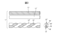
- FIG. 3 is a partially enlarged view of the filament in the first embodiment.
- the filament L includes a pair of first filaments L1, L1' and a pair of second filaments L2, L2'.
- the right side of FIG. 3 shows radial cross sections of the pair of second filaments L2, L2'.
- the second filaments L2, L2' are electric wires including conductors P2, P2' and insulating portions S2, S2' surrounding the conductors P2, P2', respectively.
- the right side of FIG. 4 which will be described later, shows that the first filaments L1, L1' include conductors P1, P1' and insulating portions S1, S1' surrounding the conductors P1, P1', respectively.
- the pair of first wires L1, L1' have a first cross-sectional area m1 that is equal to each other, and the pair of second wires L2, L2' have a second cross-sectional area m2 that is equal to each other.
- the conductor cross-sectional areas of the wires of the pair of first wires L1, L1' are equal to each other, and the conductor cross-sectional areas of the wires of the pair of first wires L2, L2' are equal to each other.
- the first cross-sectional area m1 of the pair of first wires L1, L1' is larger than the second cross-sectional area m2 of the pair of second wires L2, L2'.
- the conductor cross-sectional area of the wires of the pair of first wires L1, L1' is larger than the conductor cross-sectional area of the wires of the pair of second wires L2, L2'.
- the conductor cross-sectional area of the pair of first wires L1, L1' is 1.25 square millimeters
- the conductor cross-sectional area of the wires of the pair of first wires L2, L2' is 0.2 square millimeters.
- the outer diameter of the insulation and the outer diameter of the conductor are proportional to each other in electric wires.
- the pair of first wires L1, L1' can be a fixed member 21 of the actuator 5, for example, a power line that supplies current to the motor 10 or a power line for driving a tool attached to the wrist of a robot.
- the pair of second wires L2, L2' can be signal lines that transmit and receive control signals for the actuator 5 and signals from the sensor S and the encoder E.
- the pair of first wires L1, L1' are independent single wires that extend substantially parallel to each other and are not twisted, and the pair of second wires L2, L2' are twisted pair wires.
- the pair of first wires L1, L1' are not entangled with each other, so that the pair of first wires L1, L1' are less likely to be subjected to longitudinal stress that occurs in the insulating parts due to the pair of first wires L1, L1' being wound around each other. There is no longitudinal expansion or contraction caused by the insulating parts S1, S1' of the pair of first wires L1, L1' being wound around each other when the actuator 5 is driven.
- the insulating portions S1, S1' of the pair of first filaments L1, L1' are unlikely to break. Because the insulating portions are unlikely to break, the possibility of the conductors P1, P1' of the first filaments L1, L1' breaking is also extremely small. If the insulating portions break, they will no longer be able to withstand the stress acting on the wire material, and all stress will act directly on the conductors, so it will only be a matter of time before the conductors break after the insulating portions break.
- the pair of second filaments L2, L2' has a small diameter, they are not subjected to as great a stress as the first filaments L1, L1' when the robot 1 is driven, so the insulating parts S2, S2' of the pair of second filaments L2, L2' do not break easily, and the conductors P2, P2' do not break.
- the life of the filament L including the pair of first filaments L1, L1' and the pair of second filaments L2, L2' can be extended. Even if the insulating parts do not break, the conductors themselves will gradually break due to torsional fatigue caused by repeated torsional motion, but a life sufficient to complete the useful life of the robot can be ensured.
- FIG. 4 is a partially enlarged view of the wire in the second embodiment.
- the wire L includes a pair of first wires L1, L1' and a pair of second wires L2, L2'.
- the pair of first wires L1, L1' and the pair of second wires L2, L2' have cross-sectional areas m1, m2 similar to those described above, and a conductor cross-sectional area similar to that described above, respectively.
- both the pair of first wires L1, L1' and the pair of second wires L2, L2' are twisted pairs.
- the pair of first filaments L1, L1' is twisted looser than the pair of second filaments L2, L2'.
- circumscribing circles are shown by dashed lines around the pair of first filaments L1, L1' and the pair of second filaments L2, L2'. These circumscribing circles correspond to the outer diameter of the pair of filaments as a twisted pair, i.e., the outer twisted diameter.
- the twisted outer diameter of the pair of first filaments L1, L1' is D1
- the twisted outer diameter of the pair of second filaments L2, L2' is D2.
- the twist pitch of the pair of first filaments L1, L1' is G1
- the twist pitch of the pair of second filaments L2, L2' is G2.
- the twist pitch in this specification corresponds to the axial length of the twisted pair that is required for one of the pair of filament parts constituting the twisted pair to change the phase by 180° in the radial cross section of the twisted pair.
- the pair of first filaments L1, L1' in the second embodiment are twisted more loosely than the pair of second filaments L2, L2'.
- the outer twist diameter D1 is 4.4 millimeters
- the outer twist diameter D2 is 2.2 millimeters
- the twist pitch G1 is 50 millimeters
- the twist pitch G2 is 10 millimeters.
- the ratio R1 is about 11.4, which is greater than the ratio R2, which is about 4.5.
- the twist of the pair of first wires L1, L1' is relatively loose, even when the movable member 22 of the actuator 5 rotates relative to the fixed member 21 in a direction in which the twist of L1, L1' becomes tighter, the insulating portion of the pair of first wires L1, L1' is unlikely to be subjected to stress sufficient to cause the insulating portion to break early. For this reason, as described above, the insulating portions S1, S1' of the pair of first wires L1, L1' are unlikely to break, and therefore the conductors P1, P1' of the first wires L1, L1' are not likely to break early.
- the pair of second wires L2, L2' has a small diameter, large stress is not applied when the robot 1 is driven, and the insulating portions S2, S2' of the pair of second wires L2, L2' are not broken, and as a result, the conductors P2, P2' are not broken.
- the life of the filament L which includes a pair of first filaments L1, L1' and a pair of second filaments L2, L2', can be extended.
- the pair of first wires L1, L1' are twisted pairs, so that the laying process of the pair of first wires L1, L1' can be performed more easily and in a shorter time than the laying process of the pair of first wires L1, L1' as two solid wires in the first embodiment.
- FIG. 6A is a radial cross-sectional view of a filament in one example.
- a pair of first filaments L1, L1' and a pair of second filaments L2, L2' are surrounded by a braided shield Lb made of a conductor, and the braided shield Lb is further surrounded by a coating La made of an insulator.
- the filament L is an example of a composite cable that may include a coating La and a braided shield Lb.
- FIG. 6B is a radial cross-sectional view of a filament in another example.
- the filament L includes a covering portion La and a braided shield Lb similar to those described above, and is an example of a composite cable in which multiple pairs of first filaments L1, L1' and multiple pairs of second filaments L2, L2' are arranged within the braided shield Lb.
- the filaments L shown in FIGS. 6A and 6B are included within the scope of the present disclosure and provide the same effects as those described above.
- a wire containing at least one power line and at least one signal line passes through the robot's actuator.
- a current significantly larger than before the specification change flows in the power line as a direct current.
- the bending resistance of electric wires tends to decrease as the diameter increases. Therefore, an evaluation was carried out on the reliability of twisted pair wires, and it was found that thick twisted pair wires have a tendency for the insulation to break early, and then the conductor to completely break within a short period of time.
- each of the pair of first strands L1, L1' is a solid wire, or the pair of first strands L1, L1' is twisted more loosely than the pair of second strands L2, L2'.
- the insulating parts S1, S1' of the first strands L1, L1' will not break in a short time, and therefore the conductors P1, P1' of the first strands L1, L1' will not break prematurely.
- the pair of second strands L2, L2' is also as described above.
- the conductors P1, P1' of the pair of first filaments L1, L1' and/or the conductors P2, P2' of the pair of second filaments L2, L2' are made of soft copper wire.
- these conductors P1, P1', P2, P2' may be made of a conductor material with excellent fatigue strength, such as a copper alloy, and in this case, the bending resistance can be improved compared to the case of conductors made of soft copper wire.
- FIG. 5A is an axial cross-sectional view of an actuator based on a first modified example.
- the actuator 5-2 shown in FIG. 5A does not have a sensor S.
- the movable member 22 of the actuator 5-2 includes only the output portion 23.
- the second fixed portion 32 is fixed to the end face of the extension portion 23a, that is, the end of the hollow hole 29.
- the fixed member 21 includes the reducer 20 and the motor 10.
- FIG. 5B is an axial cross-sectional view of an actuator based on a second modified example.
- the actuator 5-3 shown in FIG. 5B is equipped with an encoder E on the rear end side of the motor 10.
- the encoder E detects the number of rotations of the motor shaft 13 and the number of rotations of the extension portion 23a, etc., using a known method.
- the fixed member 21 includes the reducer 20, the motor 10, and the encoder E.
- the first fixed portion 31 is attached to the rear end of the encoder E.
- the movable member 22 includes the output portion 23 and the sensor S.
- a driver with a hollow structure may also be mounted on the right side (rearmost end side) of the encoder E.
- the filament L may include a pair of first filaments L1, L1', a pair of second filaments L2, L2', and a pair of third filaments L3, L3' (not shown).
- the thickness of the third filaments L3, L3 is between the thickness of the first filaments L1, L1' and the thickness of the second filaments L2, L2'.
- the pair of third wires L3, L3 may be a twisted pair or may be composed of multiple single wires. Furthermore, the pair of third wires L3, L3 may have a loose twist pitch or a normal twist pitch. Even in such a case, it is included in the scope of the present disclosure.
- At least one of the embodiments described above has the effect of providing an actuator in which the filament L has a long life.
- the "actuator” here refers to a drive mechanism stored in a robot arm, etc.
- the actuator may be integrated with a housing member such as a robot arm, or the actuator itself may be a unit that can be separated from a housing member such as a robot arm.
- a fixing member In the actuator, A fixing member; a movable member that rotates relative to the fixed member; a hollow hole passing through the actuator; A filament passing through the inside of the hollow hole; A first fixing portion that fixes a portion of the filament; and a second fixing portion that fixes another portion of the filament,
- the filaments include at least a pair of first filaments having a first diameter and a pair of second filaments having a second diameter smaller than the first diameter; Each of the pair of first filaments is a solid wire, The pair of second wires is a twisted pair of wires.
- the filaments include at least a pair of first filaments having a first diameter and a pair of second filaments having a second diameter smaller than the first diameter; the pair of first wires is a twisted pair, the pair of second wire bodies is a twisted pair, a ratio of the twist pitch of the pair of first filaments to an outer diameter of the twisted bodies of the pair of first filaments is greater than a ratio of the twist pitch of the pair of second filaments to an outer diameter of the twisted bodies of the pair of second filaments.
Landscapes
- Engineering & Computer Science (AREA)
- Robotics (AREA)
- Mechanical Engineering (AREA)
- Manipulator (AREA)
Priority Applications (5)
| Application Number | Priority Date | Filing Date | Title |
|---|---|---|---|
| DE112023005976.4T DE112023005976T5 (de) | 2023-05-19 | 2023-05-19 | Aktuator und roboter |
| JP2025521583A JPWO2024241360A1 (https=) | 2023-05-19 | 2023-05-19 | |
| CN202380098123.0A CN121100047A (zh) | 2023-05-19 | 2023-05-19 | 致动器及机器人 |
| PCT/JP2023/018725 WO2024241360A1 (ja) | 2023-05-19 | 2023-05-19 | アクチュエータおよびロボット |
| TW113114628A TW202446564A (zh) | 2023-05-19 | 2024-04-19 | 致動器及機器人 |
Applications Claiming Priority (1)
| Application Number | Priority Date | Filing Date | Title |
|---|---|---|---|
| PCT/JP2023/018725 WO2024241360A1 (ja) | 2023-05-19 | 2023-05-19 | アクチュエータおよびロボット |
Publications (1)
| Publication Number | Publication Date |
|---|---|
| WO2024241360A1 true WO2024241360A1 (ja) | 2024-11-28 |
Family
ID=93589639
Family Applications (1)
| Application Number | Title | Priority Date | Filing Date |
|---|---|---|---|
| PCT/JP2023/018725 Ceased WO2024241360A1 (ja) | 2023-05-19 | 2023-05-19 | アクチュエータおよびロボット |
Country Status (5)
| Country | Link |
|---|---|
| JP (1) | JPWO2024241360A1 (https=) |
| CN (1) | CN121100047A (https=) |
| DE (1) | DE112023005976T5 (https=) |
| TW (1) | TW202446564A (https=) |
| WO (1) | WO2024241360A1 (https=) |
Citations (3)
| Publication number | Priority date | Publication date | Assignee | Title |
|---|---|---|---|---|
| JP2005144610A (ja) * | 2003-11-17 | 2005-06-09 | Fanuc Ltd | センサケーブル配線処理構造 |
| JP2007512660A (ja) * | 2003-10-23 | 2007-05-17 | コムスコープ ソリューションズ プロパティーズ,エルエルシー | ランダムに変化するローカルエリアネットワークケーブルの構成 |
| WO2023026434A1 (ja) * | 2021-08-26 | 2023-03-02 | ファナック株式会社 | 線条体固定構造、機械、ロボット、及びアクチュエータ |
Family Cites Families (1)
| Publication number | Priority date | Publication date | Assignee | Title |
|---|---|---|---|---|
| JP6506195B2 (ja) | 2016-03-09 | 2019-04-24 | ファナック株式会社 | 回転軸モジュールおよび多関節ロボット |
-
2023
- 2023-05-19 WO PCT/JP2023/018725 patent/WO2024241360A1/ja not_active Ceased
- 2023-05-19 CN CN202380098123.0A patent/CN121100047A/zh active Pending
- 2023-05-19 DE DE112023005976.4T patent/DE112023005976T5/de active Pending
- 2023-05-19 JP JP2025521583A patent/JPWO2024241360A1/ja active Pending
-
2024
- 2024-04-19 TW TW113114628A patent/TW202446564A/zh unknown
Patent Citations (3)
| Publication number | Priority date | Publication date | Assignee | Title |
|---|---|---|---|---|
| JP2007512660A (ja) * | 2003-10-23 | 2007-05-17 | コムスコープ ソリューションズ プロパティーズ,エルエルシー | ランダムに変化するローカルエリアネットワークケーブルの構成 |
| JP2005144610A (ja) * | 2003-11-17 | 2005-06-09 | Fanuc Ltd | センサケーブル配線処理構造 |
| WO2023026434A1 (ja) * | 2021-08-26 | 2023-03-02 | ファナック株式会社 | 線条体固定構造、機械、ロボット、及びアクチュエータ |
Also Published As
| Publication number | Publication date |
|---|---|
| DE112023005976T5 (de) | 2026-04-09 |
| CN121100047A (zh) | 2025-12-09 |
| TW202446564A (zh) | 2024-12-01 |
| JPWO2024241360A1 (https=) | 2024-11-28 |
Similar Documents
| Publication | Publication Date | Title |
|---|---|---|
| EP1531029B1 (en) | Cable distribution and support equipment for sensor in robot system | |
| JP5281261B2 (ja) | 張力キャリヤを備えた平ベルト状の支持駆動手段 | |
| CN103517790B (zh) | 多关节型工业用机械手 | |
| CN108369840B (zh) | 轮毂电动机用动力缆线和其布线结构以及选择方法 | |
| JP5833836B2 (ja) | 多関節型産業用ロボット | |
| JP4301984B2 (ja) | アーク溶接ロボットの溶接トーチ用線条体処理構造 | |
| CN116583386B (zh) | 线条体一体型致动器、单元以及机器人 | |
| JP7623505B2 (ja) | 線条体固定構造、機械、ロボット、及びアクチュエータ | |
| JP4001224B2 (ja) | アーク溶接ケーブル | |
| CN109382848B (zh) | 旋转轴线缆布线构造和机器人 | |
| WO2024241360A1 (ja) | アクチュエータおよびロボット | |
| JP6898577B1 (ja) | ケーブルハーネス、ケーブルハーネスの製造方法及びケーブルハーネスを有する産業用ロボット | |
| JP6882437B2 (ja) | ケーブル配線方法、ロボットの製造方法、回転軸ケーブル配線構造、及びロボット | |
| WO2024201937A1 (ja) | アクチュエータ | |
| JP2015054388A (ja) | ロボットアームおよびロボット | |
| JP2020044648A5 (ja) | ケーブル配線方法、ロボットの製造方法、回転軸ケーブル配線構造、及びロボット | |
| WO2023248349A1 (ja) | 駆動装置および駆動装置を備えるロボット | |
| JPH04269192A (ja) | 産業用ロボツト | |
| JP7849486B2 (ja) | アクチュエータ | |
| WO2024189919A1 (ja) | アクチュエータ | |
| US20250069775A1 (en) | Data and power cable assemblies | |
| JP2025047208A (ja) | 複合ケーブル及び複合ハーネス | |
| CN121215348A (zh) | 一种信号线传输用控制电缆 | |
| WO2024189788A1 (ja) | アクチュエータおよびロボット | |
| JP6149256B2 (ja) | コントロールケーブル |
Legal Events
| Date | Code | Title | Description |
|---|---|---|---|
| 121 | Ep: the epo has been informed by wipo that ep was designated in this application |
Ref document number: 23938337 Country of ref document: EP Kind code of ref document: A1 |
|
| ENP | Entry into the national phase |
Ref document number: 2025521583 Country of ref document: JP Kind code of ref document: A |
|
| WWE | Wipo information: entry into national phase |
Ref document number: 2025521583 Country of ref document: JP |
|
| WWE | Wipo information: entry into national phase |
Ref document number: 112023005976 Country of ref document: DE |