WO2024237010A1 - 通信装置、情報処理装置、制御方法、及び、プログラム - Google Patents
通信装置、情報処理装置、制御方法、及び、プログラム Download PDFInfo
- Publication number
- WO2024237010A1 WO2024237010A1 PCT/JP2024/015518 JP2024015518W WO2024237010A1 WO 2024237010 A1 WO2024237010 A1 WO 2024237010A1 JP 2024015518 W JP2024015518 W JP 2024015518W WO 2024237010 A1 WO2024237010 A1 WO 2024237010A1
- Authority
- WO
- WIPO (PCT)
- Prior art keywords
- communication
- communication device
- frame
- signal strength
- communication frame
- Prior art date
- Legal status (The legal status is an assumption and is not a legal conclusion. Google has not performed a legal analysis and makes no representation as to the accuracy of the status listed.)
- Ceased
Links
Images





Classifications
-
- H—ELECTRICITY
- H04—ELECTRIC COMMUNICATION TECHNIQUE
- H04L—TRANSMISSION OF DIGITAL INFORMATION, e.g. TELEGRAPHIC COMMUNICATION
- H04L1/00—Arrangements for detecting or preventing errors in the information received
- H04L1/12—Arrangements for detecting or preventing errors in the information received by using return channel
- H04L1/16—Arrangements for detecting or preventing errors in the information received by using return channel in which the return channel carries supervisory signals, e.g. repetition request signals
- H04L1/1607—Details of the supervisory signal
- H04L1/1657—Implicit acknowledgement of correct or incorrect reception, e.g. with a moving window
-
- H—ELECTRICITY
- H04—ELECTRIC COMMUNICATION TECHNIQUE
- H04L—TRANSMISSION OF DIGITAL INFORMATION, e.g. TELEGRAPHIC COMMUNICATION
- H04L1/00—Arrangements for detecting or preventing errors in the information received
- H04L1/0001—Systems modifying transmission characteristics according to link quality, e.g. power backoff
- H04L1/0002—Systems modifying transmission characteristics according to link quality, e.g. power backoff by adapting the transmission rate
- H04L1/0003—Systems modifying transmission characteristics according to link quality, e.g. power backoff by adapting the transmission rate by switching between different modulation schemes
-
- H—ELECTRICITY
- H04—ELECTRIC COMMUNICATION TECHNIQUE
- H04L—TRANSMISSION OF DIGITAL INFORMATION, e.g. TELEGRAPHIC COMMUNICATION
- H04L1/00—Arrangements for detecting or preventing errors in the information received
-
- H—ELECTRICITY
- H04—ELECTRIC COMMUNICATION TECHNIQUE
- H04L—TRANSMISSION OF DIGITAL INFORMATION, e.g. TELEGRAPHIC COMMUNICATION
- H04L1/00—Arrangements for detecting or preventing errors in the information received
- H04L1/0001—Systems modifying transmission characteristics according to link quality, e.g. power backoff
- H04L1/0009—Systems modifying transmission characteristics according to link quality, e.g. power backoff by adapting the channel coding
-
- H—ELECTRICITY
- H04—ELECTRIC COMMUNICATION TECHNIQUE
- H04W—WIRELESS COMMUNICATION NETWORKS
- H04W16/00—Network planning, e.g. coverage or traffic planning tools; Network deployment, e.g. resource partitioning or cells structures
- H04W16/14—Spectrum sharing arrangements between different networks
-
- H—ELECTRICITY
- H04—ELECTRIC COMMUNICATION TECHNIQUE
- H04W—WIRELESS COMMUNICATION NETWORKS
- H04W16/00—Network planning, e.g. coverage or traffic planning tools; Network deployment, e.g. resource partitioning or cells structures
- H04W16/24—Cell structures
- H04W16/28—Cell structures using beam steering
-
- H—ELECTRICITY
- H04—ELECTRIC COMMUNICATION TECHNIQUE
- H04W—WIRELESS COMMUNICATION NETWORKS
- H04W24/00—Supervisory, monitoring or testing arrangements
- H04W24/02—Arrangements for optimising operational condition
-
- H—ELECTRICITY
- H04—ELECTRIC COMMUNICATION TECHNIQUE
- H04W—WIRELESS COMMUNICATION NETWORKS
- H04W28/00—Network traffic management; Network resource management
- H04W28/02—Traffic management, e.g. flow control or congestion control
- H04W28/04—Error control
-
- H—ELECTRICITY
- H04—ELECTRIC COMMUNICATION TECHNIQUE
- H04W—WIRELESS COMMUNICATION NETWORKS
- H04W28/00—Network traffic management; Network resource management
- H04W28/02—Traffic management, e.g. flow control or congestion control
- H04W28/08—Load balancing or load distribution
- H04W28/086—Load balancing or load distribution among access entities
-
- H—ELECTRICITY
- H04—ELECTRIC COMMUNICATION TECHNIQUE
- H04W—WIRELESS COMMUNICATION NETWORKS
- H04W28/00—Network traffic management; Network resource management
- H04W28/16—Central resource management; Negotiation of resources or communication parameters, e.g. negotiating bandwidth or QoS [Quality of Service]
- H04W28/18—Negotiating wireless communication parameters
-
- H—ELECTRICITY
- H04—ELECTRIC COMMUNICATION TECHNIQUE
- H04L—TRANSMISSION OF DIGITAL INFORMATION, e.g. TELEGRAPHIC COMMUNICATION
- H04L1/00—Arrangements for detecting or preventing errors in the information received
- H04L1/12—Arrangements for detecting or preventing errors in the information received by using return channel
- H04L1/16—Arrangements for detecting or preventing errors in the information received by using return channel in which the return channel carries supervisory signals, e.g. repetition request signals
- H04L1/18—Automatic repetition systems, e.g. Van Duuren systems
- H04L1/1867—Arrangements specially adapted for the transmitter end
- H04L1/1893—Physical mapping arrangements
-
- H—ELECTRICITY
- H04—ELECTRIC COMMUNICATION TECHNIQUE
- H04W—WIRELESS COMMUNICATION NETWORKS
- H04W84/00—Network topologies
- H04W84/02—Hierarchically pre-organised networks, e.g. paging networks, cellular networks, WLAN [Wireless Local Area Network] or WLL [Wireless Local Loop]
- H04W84/10—Small scale networks; Flat hierarchical networks
- H04W84/12—WLAN [Wireless Local Area Networks]
Definitions
- the present invention relates to a device that performs communication control.
- SR processing has been considered as a technology for multiple BSSs (Basic Service Sets) to effectively use wireless media.
- BSS processing is a communication technology for efficiently using wireless media in an OBSS (Overlapping Basic Service Set) environment where multiple BSSs are arranged overlapping each other.
- OBSS Overlapping Basic Service Set
- Patent Document 1 discloses a technology that uses the BSS Color to determine whether the OBSS signal is an uplink or downlink signal and controls transmission.
- the present invention aims to provide a method that allows communication to be performed appropriately even if an error occurs when performing SR processing.
- a communication device is a communication device that performs communication compliant with IEEE 802.11, and is characterized by having a first receiving means for receiving at least a portion of a first communication frame including information indicating that Special Reuse (SR) is permitted and transmitted from a first other communication device, a detection means for detecting a second communication frame that is transmitted from a second other communication device and interferes with the reception of the communication frame, and a notification means for notifying the first communication device of an error in the reception of the communication frame based on the signal strength of the signal received by the first receiving means and the signal strength of the second communication frame detected by the detection means.
- SR Special Reuse
- FIG. 1 is a diagram showing the overall configuration of a network according to the present invention
- FIG. 2 is a diagram showing a hardware configuration according to the present invention.
- FIG. 2 is a block diagram of a functional configuration according to the present invention.
- FIG. 2 is a time sequence diagram according to the present invention.
- FIG. 2 is a diagram showing an operation flow of a communication device (AP) in the present invention.
- FIG. 2 is a diagram showing a configuration of a communication frame in the present invention.
- FIG. 2 is a diagram showing a configuration of a communication frame in the present invention.
- FIG. 2 is a diagram showing a configuration of a communication frame in the present invention.
- FIG. 2 is a diagram showing a configuration of a communication frame in the present invention.
- FIG. 2 is a diagram showing a configuration of a communication frame in the present invention.
- FIG. 1 is a diagram showing the system configuration according to this embodiment, which includes an access point device (AP) and a station device (STA).
- AP access point device
- STA station device
- FIG. 1 shows the configuration of a network constructed by communication device 111 (AP111) and a network constructed by communication device 121 (AP121) adjacent to the network constructed by AP111.
- AP111 has established a wireless communication connection with communication device 112 (STA112).
- STA112 communication device 112
- AP121 has also established a wireless communication connection with communication device 122 (STA122).
- AP111, STA112, AP121, and STA122 are each configured to be capable of communicating wireless frames that comply with the IEEE802.11bn standard, which is the successor to the IEEE802.11be standard and targets a maximum transmission speed of 46.08 Gbps.
- IEEE stands for Institute of Electrical and Electronics Engineers.
- this successor standard to 802.11be is support for highly reliable and low latency communication, AP coordination, and improved throughput during congestion.
- IEEE802.11bn the successor standard to IEEE802.11be
- wireless frames communicated using this successor standard are also called UHR (Ultra High Reliability) PPDU.
- PPDU is an abbreviation for PLCP Protocol Data Unit
- PLCP is an abbreviation for Physical Layer Convergence Protocol.
- IEEE 802.11bn and UHR were chosen for convenience, taking into account the goals to be achieved by the successor standards and the key features of the standards, and may be different names once the standards have been fully formulated. However, please note that this specification and the appended claims are essentially applicable to all successor standards to the 802.11be standard that can be supported.
- Each communication device can communicate at frequencies of 2.4 Hz, 3.6 GHz, 5 GHz, 6 GHz, and 45 GHz and 60 GHz, known as millimeter waves.
- the frequency bands used by each communication device are not limited to these, and different frequency bands, such as the Sub1 GHz band, may be used.
- each communication device can communicate using bandwidths of 20 MHz, 40 MHz, 80 MHz, 160 MHz, 320 MHz, 540 MHz, 640 MHz, 1080 MHz, and 2160 MHz.
- the bandwidths used by each communication device are not limited to these, and different bandwidths, such as 240 MHz and 4 MHz, may be used.
- AP111, STA112, AP121, and STA122 can perform OFDMA communication conforming to the IEEE802.11 standard, thereby realizing multi-user (MU, Multi User) communication that multiplexes the signals of multiple users.
- OFDMA stands for Orthogonal Frequency Division Multiple Access.
- RU Resource Unit
- the AP can communicate in parallel with multiple STAs within a specified bandwidth.
- each communication device is described as being compatible with the IEEE802.11bn standard, it may also be compatible with a legacy standard that is a standard that precedes the IEEE802.11bn standard or a standard that follows the IEEE802.11bn standard. Specifically, each communication device may be compatible with at least one of the IEEE802.11a/b/g/n/ac/ax/be standards. In addition to the IEEE802.11 series standards, it may also be compatible with other communication standards such as Bluetooth (registered trademark), NFC, UWB, ZigBee, and MBOA. UWB stands for Ultra Wide Band, and MBOA stands for Multi Band OFDM Alliance. NFC stands for Near Field Communication. UWB includes wireless USB, wireless 1394, WiNET, and the like.
- the AP 111 and the AP 121 may also be compatible with a communication standard for wired communication such as a wired LAN.
- Specific examples of the AP 111 and the AP 121 include, but are not limited to, a wireless LAN router and a personal computer (PC).
- the AP 111 and the AP 121 may also be information processing devices such as wireless chips capable of performing wireless communication conforming to the IEEE 802.11bn standard.
- Specific examples of the STA 112 and the STA 122 include, but are not limited to, a camera, a tablet, a smartphone, a PC, a mobile phone, a video camera, a headset, and the like.
- the STA 112 and the STA 122 may also be information processing devices such as wireless chips capable of performing wireless communication conforming to the IEEE 802.11bn standard.
- the wireless network in FIG. 1 is composed of two APs and two STAs, but the number and arrangement of the APs and STAs are not limited to this.
- Each communication device applies Spatial Reuse (SR) that complies with the IEEE 802.11 standard, for example, and can transmit communication frames even if another network is communicating in the same frequency band.
- SR Spatial Reuse
- the device when another communications device is transmitting a signal, the device identifies whether or not the signal is intended for the BSS to which the device belongs when the device receives the signal. If the signal is intended for a BSS other than the one to which the device belongs, the device determines whether or not the transmitted signal from the device affects the other BSS, and if it determines that there is no effect, transmits the signal from the device, enabling efficient use of the wireless medium.
- the OBSS PD-based SR method dynamically changes the carrier sense level at which the device can transmit its own signal by controlling the carrier sense threshold and transmission power when the received signal belongs to another BSS, and transmits the signal.
- the SRP method uses a trigger frame to notify the BSS to which the access point (AP) belongs of a parameter value related to the tolerable reception interference level, and terminals belonging to other BSSs determine the transmission level based on that value and transmit signals.
- FIG. 2 shows an example of the hardware configuration of AP 111 in this embodiment.
- AP 111 has a storage unit 201, a control unit 202, a function unit 203, an input unit 204, an output unit 205, a communication unit 206, and an antenna 207. Note that there may be multiple antennas.
- the storage unit 201 is composed of one or more memories such as ROM and RAM, and stores various information such as computer programs for performing various operations described below and communication parameters for wireless communication.
- ROM Read Only Memory
- RAM Random Access Memory
- storage units 201 may also use storage media such as flexible disks, hard disks, optical disks, magneto-optical disks, CD-ROMs, CD-Rs, magnetic tapes, non-volatile memory cards, and DVDs.
- the storage unit 201 may also be equipped with multiple memories.
- the control unit 202 is configured with one or more processors, such as a CPU or MPU, and controls the entire Non-AP MLD 101 by executing a computer program stored in the storage unit 201.
- the control unit 202 may control the entire Non-AP MLD 101 in cooperation with the computer program stored in the storage unit 201 and an OS (Operating System).
- the control unit 202 also generates data and signals (wireless frames) to be transmitted in communication with other communication devices.
- CPU stands for Central Processing Unit
- MPU stands for Micro Processing Unit.
- the control unit 202 may also be equipped with multiple processors, such as multi-core processors, and the multiple processors may control the entire AP 111.
- the control unit 202 also controls the function unit 203 to execute predetermined processes such as wireless communication, imaging, printing, and projection.
- the functional unit 203 is hardware that enables the AP 111 to execute a specified process. If the functional unit is a printer, it prints image data acquired via the communication unit 206. If the functional unit is a scanner, it transmits image data generated by scanning with the scanner to an external device via the communication unit 206. If the functional unit is a camera, it transmits image data captured by the camera to an external device via the communication unit 206.
- the input unit 204 is composed of a touch panel, keyboard, buttons, etc., and receives various operations from the user.
- the output unit 205 outputs various types of data to the user via a monitor screen or speaker.
- output by the output unit 205 may be a display on a monitor screen, audio output by a speaker, vibration output, etc.
- Both the input unit 204 and the output unit 205 may be realized by a single module, such as a touch panel.
- the input unit 204 and the output unit 205 may be integrated with the AP 111, or may be separate.
- the communication unit 206 controls wireless communication conforming to the IEEE 802.11 series standards.
- the communication unit 206 may also control wireless communication conforming to other IEEE 802.11 series standards in addition to the IEEE 802.11ax standard, and may control wired communication such as a wired LAN.
- the communication unit 206 controls the antenna 207 to transmit and receive signals for wireless communication generated by the control unit 202.
- the STA 112 may control wireless communication in accordance with these communication standards.
- the AP 111 can perform wireless communication in accordance with multiple communication standards, it may be configured to have separate communication units and antennas compatible with each communication standard.
- the AP 111 communicates data such as image data, document data, and video data with the AP 111 via the communication unit 206.
- the antenna 207 may be configured as a separate entity from the communication unit 206, or may be configured together with the communication unit 206 as a single module.
- the antenna 207 is an antenna capable of communication in any of the 2.4 GHz, 5 GHz, and 6 GHz bands.
- the AP 111 has one antenna, but it may have multiple antennas. Alternatively, it may have a different antenna for each frequency band. Furthermore, if the AP 111 has multiple antennas, it may have a communication unit 206 corresponding to each antenna.
- STA112 is assumed to have the same hardware configuration as AP111, but is not limited to this.
- the configuration of the input unit 204 and output unit 205 may be different between each STA and AP111.
- AP121 and STA122 are also assumed to have the same hardware configuration as AP111.
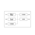
- FIG. 3 shows a block diagram of the functional configuration of AP111 in this embodiment.
- this is a diagram of a functional configuration that is realized by one or more processors executing programs stored in one or more memories.
- AP121, STA112, and STA122 also have a similar configuration.
- AP111 is assumed to have a wireless LAN control unit 301. Note that the number of wireless LAN control units is not limited to one, and may be two, or three or more.
- AP111 further has a frame processing unit 302, an SR management unit 303, a UI control unit 304, a memory unit 305, and a wireless antenna 306.
- the wireless LAN control unit 301 is configured to include an antenna and circuit for transmitting and receiving wireless signals to and from other wireless LAN devices, as well as a program for controlling them.
- the wireless LAN control unit 301 executes wireless LAN communication control based on the frames generated by the frame generation unit 302 in accordance with the IEEE 802.11 standard series.
- the frame processing unit 302 processes wireless control frames sent and received by the wireless LAN control unit 301.
- the contents of the wireless control generated and analyzed by the frame processing unit 302 may be restricted by settings stored in the memory unit 305. They may also be changed by user settings from the UI control unit 304.
- the information on the generated frame is sent to the wireless LAN control unit 301 and transmitted to the communication partner.
- the information on the frame received by the wireless LAN control unit 301 is passed to the frame processing unit 302 and analyzed.
- the SR management unit 303 determines whether transmission is possible based on the parameters collected up to that point via the frame processing unit. If transmission is possible, it determines the signal strength, modulation level, and packet length of the communication frame to be transmitted, and generates a transmission packet via the frame generation unit 302.
- the UI control unit 304 is configured to include hardware related to a user interface, such as a touch panel or buttons for accepting operations on the AP 111 by a user (not shown) of the AP 111, and a program for controlling these.
- the UI control unit 304 also has a function for presenting information to the user, such as displaying images or outputting audio.
- the memory unit 305 is a storage device that can be configured with ROM, RAM, etc., for storing the programs and data that AP111 operates on.
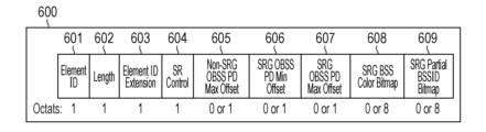
- Figures 6A and 6B show examples of frame formats in the MAC layer, and show examples of the formats of information elements (IEs) related to the SR processing functions.
- Information related to SR processing is included in MAC frames and transmitted, making it possible to perform control related to SR processing.
- Figures 6A and 6B show the format of the SR_Parameter_set element.
- the SR_Parameter_set element 600 is composed of multiple fields. Element_ID 601, Length 602, and Element_ID_Extension 603 are fields containing basic information for identifying the data of the information element.
- the SR_Control field 604 allows for more detailed control related to SR processing using the parameters of the subfields described below.
- the Non-SRG (SR_Group)_OBSS_PD_Max_Offset field 605 is used to generate the value of the Non-SRG_OBSS_PD_Max parameter.
- the SRG_OBSS_PD_Min_Offset field 606 is used to generate the value of the SRG_OBSS_PD_Min parameter.
- the SRG_OBSS_PD_Max_Offset field 607 is used to generate the value of the SRG_OBSS_PD_Max parameter.
- the OBSS_PD-based SR method is further classified into two processing types. One is processing using the Non-SRG_OBSS_PD level, which is a processing method when a packet other than an SRG is detected. The other is processing using the SRG_OBSS_PD level, which is a processing method when an SRG packet is detected.
- the above mentioned fields 605, 606, and 607 are parameters related to these two processing methods and are used to calculate the signal strength value used for packet detection.
- the SRG_BSS_Color_Bitmap field 608 is a field that indicates, in a bitmap, the value of the BSS color used by the SRG to which the device transmitting the signal belongs as a member.
- the SRG Partial BSSID Bitmap field 609 is a field that indicates, in a bitmap, the partial value of the BSSID used by the SRG to which the device transmitting the signal belongs as a member.
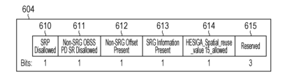
- the SR_Control field 604 is composed of multiple subfields.
- the SRP_Disallowed subfield 610 indicates whether SR processing using the SRP-based SR method is disabled in the wireless network established by the AP.
- the Non-SRG_OBSS_PD_SR_Disallowed field 611 indicates whether SR processing using the Non-SRG_OBSS_PD level is disabled in the wireless network established by the AP.
- the Non-SRG_Offset_Present subfield 612 indicates whether the Non-SRG_OBSS_PD_Max_Offset field 605 is included in the frame.
- the SRG_Information_Present subfield 613 indicates whether the aforementioned fields 606, 607, 608, and 609 are included in the SR_Parameter_set element.
- the HESIGA_Spatial_reuse_value15_allowed field 614 indicates whether the value of SRP_AND_NON_SRG_OBSS_PD_PROHIBITED can be set for SPATIAL_REUSE, which is a parameter in the TXVECTOR that passes between the MAC and PHY. Using this parameter, SR processing using the SRP method and the OBSS_PD method using the Non_SRG_OBSS_PD level can be prohibited during the transmission of the target PPDU.
- SR_Parameter_set element 600 When SR processing is not used in the constructed wireless network, the above-mentioned SR_Parameter_set element 600 is used. The value of the SRG_Information_Present subfield 613 included in the SR_Parameter_set element 600 is set to invalid (0). As a result, information related to SRG is not included in the SR_Parameter_set element. Therefore, the wireless network is in a state where no SRG exists, and SR processing using the SRG_OBSS_PD level in the OBSS_PD-based SR method is not performed. Similarly, the value of the SRP_Disabled subfield 610 is set to valid (1).
- the value of the Non-SRG_OBSS_PD_SR_Disallowed field 611 is set to enabled (1). This disallows SR processing using the Non-SRG_OBSS_PD level of the OBSS_PD-based SR method in the wireless network.
- the SR_Parameter_set element set with these values is added as an information element to the wireless frame (beacon, Probe_Response, etc.) that the communication device sends to the Client, and notified. This makes it possible to restrict the use of SR processing in the wireless network.
- the input unit 204 and the output unit 205 may display and notify the user that SR processing will not be used in the wireless network.
- the input unit 204 may allow the user to select whether or not to use SR processing in the wireless network.
- the method of disallowing the use of SR processing in a wireless network is just one example and is not limited to this. It may also be achieved by controlling other parameters. For example, it may be controlled using parameters included in the HE_Capabilities element added to the MAC frame. For example, the SRP-based_SR_Support subfield in the PHY_Capabilities_Information field can be used. This indicates whether or not SR processing of the SRP method is supported. Also, an HE_Capability element indicating that SR processing is not supported may be added to a specific wireless frame and transmitted.
- this may be achieved by controlling the parameters of the header information of the PHY frame.
- the U-SIG of the PHY frame described above may be used.
- a wireless frame may be transmitted that includes a physical header in which the parameter values SRP_DISALLOW and SPR_AND_NON_SRG_OBSS_PD_PHOHIBITED are set as the value of this field.
- the value of the SRG_Information_Present subfield 613 contained in the SR_Parameter_set element 600 is set to valid (1).
- information is entered into the fields 606, 607, 608, and 609 related to SRG, and added to the SR_Parameter_set element. This makes the SRG information valid in the wireless network constructed by the GO.
- the value of the SRP_Disallowed subfield 610 is disabled (0). This allows SR processing using the SRP-based SR method in the wireless network created by the AP.
- the value of the Non-SRG_OBSS_PD_SR_Disallowed field 611 is disabled (0). This allows SR processing using the Non-SRG_OBSS_PD level of the OBSS_PD-based SR method in the wireless network created by the AP.
- the SR_Parameter_set element set with these values is added as an information element to the wireless frame (beacon, Probe_Response, etc.) that the AP sends to the Client. This allows the use of SR processing on the Client side.
- the method of permitting the use of SR processing is not limited to this. Parameters of other information elements that can be added to MAC frames may be controlled and transmitted. Also, a value that allows the use of SR processing may be set in the Spatial_Reuse field, which is included in a field in the header of the PHY frame, and a wireless frame may be transmitted. Alternatively, another wireless frame may be extended and transmitted for notification.
- FIGS 6C and 6D show an example of the PHY frame structure of a PPDU communicated by a communication device in this embodiment.
- PPDU is an abbreviation for Physical Layer (PHY) Protocol Data Unit.
- PHY Physical Layer
- FIG. 6D shows an example of the PHY frame structure of a UHR TB PPDU communicated by a communication device in this embodiment.
- PPDU is an abbreviation for Physical Layer (PHY) Protocol Data Unit.
- PHY Physical Layer
- UHR TB PPDU is shown as an example.
- TB is an abbreviation for Trigger-Based.
- This frame is composed of L-STF 621, L-LTF 622, L-SIG 623, RL-SIG 624, U-SIG 625, UHR-STF 626, and UHR-LTF 627 from the beginning.
- UHR-LTF 627 is followed by Data field 628 and Packet Extension 629.
- STF stands for Short Training Field
- LTF stands for Long Training Field
- SIG stands for Signal.
- L- stands for Legacy, for example L-STF stands for Legacy Short Training Field.
- UHR stands for Ultra High Reliability
- UHR-STF stands for Ultra High Reliability Short Training Field.
- RL-SIG stands for Repeated Legacy Signal
- U-SIG stands for Universal Signal.
- L-STF621, L-LTF622, and L-SIG623 are backward compatible with the IEEE802.11a/b/g/n/ac/ax/be standards, which are legacy standards established before the IEEE802.11bn standard.
- L-STF621, L-LTF622, and L-SIG623 are legacy fields that can be decoded by communication devices that support the IEEE802.11 series standards that existed before the IEEE802.11be standard.
- L-STF621 is used for detecting wireless packet signals, automatic gain control (AGC), timing detection, etc.
- L-LTF302 is used for high-precision frequency and time synchronization, and for acquiring propagation channel information (CSI, Channel State Information).
- L-SIG623 is used to transmit control information including data transmission rate and packet length information.
- RL-SIG is used to identify that the standard is a later version of the IEEE802.11ac standard. RL-SIG624 may be omitted.
- UHR-STF626 and UHR-LTF627 are fields that can be decoded by communication devices that comply with the IEEE802.11 UHR standard.
- L-STF621, L-LTF622, L-SIG623, RL-SIG624, U-SIG625, UHR-STF626, and UHR-LTF627 are collectively referred to as the PHY preamble.
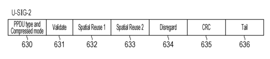
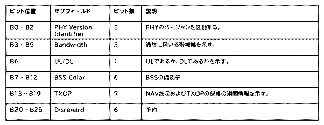
- U-SIG625 is divided into two fields: the U-SIG-1 field and the U-SIG-2 field.
- the U-SIG-1 field consists of the subfields shown in Table 1.
- the U-SIG-2 field consists of the subfields shown in Table 2.
- the device that executes PSR-based spatial reuse determines the upper limit of transmission power based on the PSR value indicated by the subfield.
- (Embodiment 1) 4 is a time sequence diagram in this embodiment in which the STA 112 transmits a communication frame permitting SR to the AP 111. The flow of operations in this embodiment will be described with reference to this diagram.
- the communication frame 401 sent by STA112 to AP111 contains information permitting OBSS PD-based SR, that is, information indicating that OBSS PD-based SR is permitted, in the PHY header.
- the information indicating that OBSS PD-based SR is permitted is contained in the PHY frame, but it may be contained in the MAC frame.
- STA122 which is included in the network established by AP121, detects from the PHY header of the communication frame 401 sent by STA112 that OBSS PD-based SR is permitted, and transmits a communication frame 402 using SR to AP121 in accordance with the IEEE802.11 standard.
- AP111 would normally like to receive communication frame 401 transmitted by STA112, but STA122, which belongs to the OBSS, is closer to AP111 than STA112. Therefore, it is not possible to ensure a sufficient ratio of the strength of the signal from STA112, which is the desired wave, to the signal from STA122, which is the interfering wave. In other words, the received signal cannot be demodulated correctly because the received SINR (Signal-to-Interference plus Noise power Ratio), which is the ratio of the received signal power to the interference and noise power taking into account OBSS interference, is insufficient in AP111.
- SINR Signal-to-Interference plus Noise power Ratio
- STA122 Before STA122 starts transmitting communication frame 402, it reads the PHY header contained in communication frame 401 transmitted by STA112, and also ensures a backoff time to avoid contention with other terminals. Therefore, AP111 is able to receive at least the PHY header portion of communication frame 401 transmitted by STA112, and is therefore able to detect information such as the signal strength and frame length of communication frame 401 transmitted by STA112.
- the signal strength of the communication frame 402 transmitted by STA122 at AP111 can be detected. Also, if the signal strength of the communication frame 402 transmitted by STA122 at AP111 is stronger than the signal strength of the communication frame 401 transmitted by STA112, the signal strength of the communication frame 402 transmitted by STA122 at AP111 can be detected.
- Ack Acknowledgement
- the AP 111 was not able to successfully complete the reception of the communication frame 401 from the STA 112 by allowing SR through the process up to this point, the AP 111 was able to obtain three pieces of information.
- the first is the signal strength of the signal transmitted from the STA 112
- the second is the signal strength of the signal transmitted from the STA 122
- the third is the address of the STA 122.
- the address is a MAC address, but other information may be used as long as it is information that can identify the device.
- the STA 112 that transmitted the communication frame 401 to the AP 111 does not obtain these pieces of information.
- AP 111 notifies STA 112 of the above three pieces of information (signal strength of the signal transmitted from STA 112, signal strength of the signal transmitted from STA 122, and address of STA 122) in an SR Fail Report frame 404.
- three pieces of information are used, but at least one piece of information may be notified, or three or more pieces of information may be notified.
- STA 112 implements measures such as the following based on the information received as the SR Fail Report when retransmitting the communication frame that AP 111 was unable to receive.
- MCS modulation and coding scheme
- the modulation and coding scheme (MCS) of the communication frame is changed (lowered) so that the AP 111 can demodulate the communication frame even if the SINR is low.
- Increase the signal strength per frequency so that the SINR is higher.
- the signal strength of communication frame 402 from STA122 at AP111 is equal to or greater than a certain level, even if STA112 transmits a communication frame that allows SR, the signal strength from STA122 is strong at AP111, making it highly likely that AP111 will not be able to correctly demodulate the communication frame that uses SR, and so it is possible to determine not to use SR.
- Whether the source device transmitting the jamming wave is STA122 can be determined by reading the source information in the MAC header.
- the SR Fail Report 404 does not need to be issued every time the AP 111 fails to receive a communication frame that allows SR.
- a reception frame error rate (FER) caused by SR exceeds a specified percentage, for example 10%, an SR Fail Report is issued. If the FER is less than 10%, communication capacity can be maintained by not issuing an SR Fail Report and instead processing it as a conventional reception error.
- FER reception frame error rate
- Flowchart 500 in FIG. 5 is a flow chart showing a series of steps in this embodiment in which AP 111 is unable to successfully receive a communication frame for which SR has been permitted from STA 112 and issues an SR Fail Report.
- the processing of S501 to S507 is realized, for example, by the control unit 202 of AP 111 executing a program stored in the memory unit 201.
- AP111 and STA112 establish a wireless communication connection so that they can communicate wirelessly. Then, they start receiving communication frames that allow SR from STA112. Since a communication frame that allows SR indicates that SR is allowed in the PHY header section, the PHY header section of the communication frame is successfully received by AP111.
- AP111 detects the signal strength of the communication frame sent from STA112 (S501). In particular, AP111 detects the received signal strength at AP111 of the communication frame sent from STA112.
- AP111 receives the communication frames from STA122 (S502). At this time, AP111 is in a state where it can receive communication frames from both STA112 and STA122.
- AP 111 determines whether it is no longer possible to demodulate the communication frame from STA 112 (S503). If AP 111 can continue to demodulate the communication frame from STA 112 (no in S503), it continues the conventional reception process and ends the process.
- AP111 If AP111 is unable to demodulate the communication frame from STA112 (yes in S503), it waits until the communication frame from STA112 ends based on the frame length obtained from the header of the communication frame from STA112, and then detects the signal strength of the communication frame from STA122 while only the communication frame from STA122 is being transmitted. In other words, AP111 detects the signal strength at AP111 of the communication frame transmitted by STA122 (S504).
- AP111 determines that transmission of the communication frame from STA122 has ended (S505).
- AP121 If the communication frame sent from STA122 is correctly received by its destination AP121, AP121 returns an Ack to STA122. AP111 intercepts the Ack and detects the MAC address of STA122 (S506).
- AP111 transmits the information obtained in the series of processes up to this point, namely, the signal strength of the communication frame from STA112 at AP111, the signal strength of the communication frame from STA122, and the MAC address of STA122, as an SR Fail Report to STA112 (S507).
- the AP can notify the STA that sent the communication frame to itself of an error in the communication frame. At this time, it is also possible to notify the STA of information that will be useful when it resends the data.
- Flowchart 510 in FIG. 5 is a flowchart showing the processing performed when STA 112 receives an SR Fail Report from AP 111.
- the processing of this flowchart is realized, for example, by the control unit 202 of STA 112 executing a program stored in the storage unit 201.
- STA112 receives the SR Fail Report sent from AP111 in S507 (S511).
- STA112 determines whether or not to retransmit the communication frame for which an error occurred based on information contained in the SR Fail Report received in S511, such as the signal strength of the signal transmitted from STA112 at AP111, the signal strength of the signal transmitted from STA122, the address of STA122, etc. (S512). If it is determined not to retransmit, the process ends.
- the STA 112 performs one or more adjustments, such as changing the MCS of the communication frame and retransmitting the communication frame, changing the signal strength and retransmitting the communication frame, or retransmitting a communication frame indicating that SR is prohibited, before retransmitting the communication frame (S513). That is, in this case, the above-mentioned 1.
- the modulation and coding scheme (MCS) of the communication frame is changed (lowered) so that the AP 111 can demodulate the communication frame even if the SINR is low. 2. Increase the signal strength per frequency so that the SINR is higher. 3. It is determined that SR is not to be used, and the PHY header is modified to prohibit SR, i.e., the transmission of communication frames indicating that SR is permitted is stopped, and a communication frame indicating that SR is prohibited is transmitted.
- MCS modulation and coding scheme
- One or more of the above processes are performed to transmit the communication frame. For example, the parameters of the corresponding fields of the frames shown in Figures 6A to 6D are changed and the communication frame is transmitted.
- wireless communication media such as wireless USB, MBOA, Bluetooth (registered trademark), UWB, ZigBee, and NFC may be used to apply the communication to a predetermined frame.
- MBOA stands for Multi Band OFDM Alliance.
- UWB includes wireless USB, wireless 1394, and WINET.
- the present invention can also be realized by supplying a program that realizes one or more of the functions of the above-mentioned embodiments to a system or device via a network or storage medium, and having one or more processors in the computer of the system or device read and execute the program. It can also be realized by a circuit (e.g., an ASIC) that realizes one or more functions.
- a circuit e.g., an ASIC
Landscapes
- Engineering & Computer Science (AREA)
- Computer Networks & Wireless Communication (AREA)
- Signal Processing (AREA)
- Quality & Reliability (AREA)
- Mobile Radio Communication Systems (AREA)
- Detection And Prevention Of Errors In Transmission (AREA)
Abstract
SRによって受信側で通信フレームの復調が正しく実行できない場合には、受信側で検出された希望波の信号強度と妨害波の信号強度を送信側に通知することにより、送信側から再送される通信フレームでは通信を実行するために最適なパラメータに更新できる。
Description
本発明は、通信制御を行う装置に関する。
近年、多数の無線通信機器が存在する環境での無線媒体の効率的な利用を目指すIEEE802.11の種々の規格が検討されている。この検討においては複数のBSS(Basic Service Set)が無線媒体を有効に使用するための技術として空間再利用(SR:Spatial Reuse)処理が検討されている。SR処理は、複数のBSSが重なって配置されているようなOBSS(Overlapping Basic Service Set)環境下で効率よく無線媒体を利用するための通信技術である。BSSを識別する識別情報としてはBSSカラー(BSS Color)という情報を物理層ヘッダに含めて送信する方法が検討されている。特許文献1ではBSSカラーを用いて、OBSSの上り信号であるか下り信号であるかを判別して送信制御を行う技術が開示されている。
従来のSR処理では、SRを許容した通信パケットが、想定以上の強度で他のOBSSの機器からの妨害波を受けた場合、装置は当該通信パケットをうまく受信できずエラーとなっていた。ここでのエラーの発生、エラーの原因を装置が適切に把握できておらず、好適な通信を行えていなかった。
上記課題を鑑み、本発明はSR処理を実行する場合にエラーが発生したとしても好適に通信を実行することが可能な方法を提供することを目的とする。
上記目的を達成するため、本発明の一態様に係る通信装置は、IEEE802.11に準拠した通信を実行する通信装置であって、第一の他の通信装置から送信されるSpecial Reuse (SR)を許可することを示す情報を含む第一の通信フレームの少なくとも一部を受信する第一の受信手段と、第二の他の通信装置から送信される、前記通信フレームの受信を妨害する第二の通信フレームを検出する検出手段と、前記第一の受信手段で受信した信号の信号強度と、前記検出手段で検出した第二の通信フレームの信号強度とに基づいて、前記第一の通信装置に前記通信フレームの受信のエラーを通知する通知手段と、を有することを特徴とする。
SR処理を実行する場合にエラーが発生したとしても好適に通信を実行することが可能となる。
以下、添付の図面を参照して、本発明の実施形態を詳細に説明する。なお、以下の実施形態において示す構成は一例に過ぎず、本発明は図示された構成に限定されるものではない。
(無線通信システムの構成)
図1は、本実施形態にかかるシステム構成図であって、アクセスポイント装置(AP)とステーション装置(STA)を含む。
図1は、本実施形態にかかるシステム構成図であって、アクセスポイント装置(AP)とステーション装置(STA)を含む。
図1は、通信装置111(AP111)が構築するネットワークと、AP111が構築するネットワークに隣接する通信装置121(AP121)が構築するネットワークの構成を示す。AP111は、通信装置112(STA112)と無線通信接続を確立している。つまり、AP111とSTA112とはAssociation Request/Response、4-way handshake等の処理により接続を確立している状態である。また、AP121は、通信装置122(STA122)とで無線通信接続を確立している。
AP111、STA112、AP121、STA122の各々は、最大伝送速度46.08Gbpsを目標とするIEEE802.11be規格の後継規格であり、IEEE802.11bn規格に準拠した無線フレームの通信を実行可能に構成される。なお、IEEEはInstitute of Electrical and Electronics Engineersの略である。
この、802.11beの後継規格では、高信頼通信や低レイテンシ通信のサポートやAP協調、混雑時のスループット向上を主たる特徴として掲げている。上記を踏まえ、本実施形態では、IEEE802.11beの後継規格を、IEEE802.11bnと呼称する。また、当該後継規格で通信する無線フレームをUHR(Ultra High Reliability) PPDUとも呼称する。PPDUは、PLCP Protocol Data Unitの略であり、PLCPは、Physical Layer Convergence Protocolの略である。
なお、IEEE802.11bn、UHRという名称は後継規格で達成すべき目標や当該規格で目玉となる特徴を踏まえて便宜上設けられたものであり、規格の策定が完了した状態において別の名称となりうる。一方、本明細書及び添付の特許請求の範囲は、本質的には、802.11be規格の後継規格であってサポートしうるすべての後継規格に適用可能であることに留意されたい。
各通信装置は、2.4Hz帯、3.6GHz帯、5GHz帯、6GHz帯や、ミリ波と呼ばれる45GHz帯、60GHz帯の周波数において通信することができる。各通信装置が使用する周波数帯は、これに限定されるものではなく、例えばSub1GHz帯のように、異なる周波数帯を使用してもよい。また、各通信装置は、20MHz、40MHz、80MHz、160MHz、320MHz、540MHz、640MHz、1080MHz、および2160MHzの帯域幅を使用して通信することができる。各通信装置が使用する帯域幅は、これに限定されるものではなく、例えば240MHzや4MHzのように、異なる帯域幅を使用してもよい。
AP111、STA112、AP121、STA122は、IEEE802.11規格に準拠したOFDMA通信を実行することで、複数のユーザの信号を多重する、マルチユーザ(MU、Multi User)通信を実現することができる。OFDMAは、Orthogonal Frequency Division Multiple Access(直行周波数分割多元接続)の略である。OFDMA通信では、分割された周波数帯域の一部(RU、Resource Unit)が各STAにそれぞれ重ならないように割り当てられ、各STAの搬送波が直行する。そのため、APは規定された帯域幅の中で複数のSTAと並行して通信することができる。
なお、各通信装置はIEEE802.11bn規格に対応するとしたが、IEEE802.11bn規格より前の規格であるレガシー規格やIEEE802.11bn規格より後の規格に対応していてもよい。具体的には、各通信装置はそれぞれIEEE802.11a/b/g/n/ac/ax/be規格の少なくともいずれか一つに対応していてもよい。また、IEEE802.11シリーズ規格に加えて、Bluetooth(登録商標)、NFC、UWB、ZigBee、MBOAなどの他の通信規格に対応していてもよい。なお、UWBはUltra Wide Bandの略であり、MBOAはMulti Band OFDM Allianceの略である。また、NFCはNear Field Communicationの略である。UWBには、ワイヤレスUSB、ワイヤレス1394、WiNETなどが含まれる。また、有線LANなどの有線通信の通信規格に対応していてもよい。AP111、AP121の具体例としては、無線LANルーターやパーソナルコンピュータ(PC)などが挙げられるが、これらに限定されない。またAP111、AP121は、IEEE802.11bn規格に準拠した無線通信を実行することができる無線チップなどの情報処理装置であってもよい。また、STA112、STA122の具体的な例としては、カメラ、タブレット、スマートフォン、PC、携帯電話、ビデオカメラ、ヘッドセットなどが挙げられるが、これらに限定されない。また、STA112、STA122は、IEEE802.11bn規格に準拠した無線通信を実行することができる無線チップなどの情報処理装置であってもよい。また、図1の無線ネットワークは2台のAPと2台のSTAによって構成されているが、APおよびSTAの台数や配置はこれに限定されない。
各通信装置は、例えばIEEE802.11規格に準拠したSpatial Reuse(SR:空間再利用)を適用しており、他方のネットワークが同一周波数帯域で通信中であっても通信フレームを送信することができる。
また、SR処理を用いた通信(空間再利用通信)では、他の通信装置が信号を送信している場合に、自装置で当該信号を受信した際に当該信号が自装置の属するBSS向けの信号であるか否かを識別する。そして、当該信号が自装置の属するBSS以外に向けた信号である場合、自装置の送信信号が他のBSSに影響を与えるか否かを判定し、影響がないと判定された場合に、自装置から信号を送信することで無線媒体の効率的な利用を可能にしている。なお、具体的な動作として、OBSS_PD(Overlapping BSS Packet Detect)-based SR方式とSRP(Spatial Reuse Parameters)-based SR方式の2つの方式がある。
OBSS PD-based SR方式は、受信信号が他のBSSに属する場合に、キャリアセンスの閾値と送信電力を制御することで、自装置の信号を送信可能なキャリアセンスレベルを動的に変更して信号を送信する方式である。SRP方式は、アクセスポイント(AP)が属するBSSにおいて許容できる受信干渉レベルに関するパラメータ値をトリガーフレームを用いて通知し、他のBSSに属する端末はその値に基づいて送信レベルを決定して信号を送信する方式である。
図2に、本実施形態におけるAP111のハードウェア構成例を示す。AP111は、記憶部201、制御部202、機能部203、入力部204、出力部205、通信部206、およびアンテナ207を有する。なお、アンテナは複数でもよい。
記憶部201は、ROMやRAM等の1以上のメモリにより構成され、後述する各種動作を行うためのコンピュータプログラムや、無線通信のための通信パラメータ等の各種情報を記憶する。ROMはRead Only Memoryの、RAMはRandom Access Memoryの夫々略である。なお、記憶部201として、ROM、RAM等のメモリの他に、フレキシブルディスク、ハードディスク、光ディスク、光磁気ディスク、CD-ROM、CD-R、磁気テープ、不揮発性のメモリカード、DVDなどの記憶媒体を用いてもよい。また、記憶部201が複数のメモリ等を備えていてもよい。
制御部202は、例えば、例えばCPUやMPU等の1以上のプロセッサにより構成され、記憶部201に記憶されたコンピュータプログラムを実行することにより、Non-AP MLD101の全体を制御する。なお、制御部202は、記憶部201に記憶されたコンピュータプログラムとOS(Operating System)との協働により、Non-AP MLD101の全体を制御するようにしてもよい。また、制御部202は、他の通信装置との通信において送信するデータや信号(無線フレーム)を生成する。
なお、CPUはCentral Processing Unitの、MPUは、Micro Processing Unitの略である。また、制御部202がマルチコア等の複数のプロセッサを備え、複数のプロセッサによりAP111全体を制御するようにしてもよい。また、制御部202は、機能部203を制御して、無線通信や、撮像、印刷、投影等の所定の処理を実行する。
機能部203は、AP111が所定の処理を実行するためのハードウェアである。機能部がプリンタであれば通信部206を介して取得した画像データをプリントする。また機能部がスキャナであればスキャナでスキャンして生成した画像データを通信部206を介して外部装置に送信する。さらに機能部がカメラである場合はカメラで撮像した画像データを通信部206を介して外部装置に送信する。
入力部204は、タッチパネルやキーボード、ボタン等で構成され、ユーザからの各種操作の受付を行う。出力部205は、モニタ画面やスピーカーを介して、ユーザに対して各種出力を行う。ここで、出力部205による出力とは、モニタ画面上への表示や、スピーカーによる音声出力、振動出力などであってもよい。なお、タッチパネルのように入力部204と出力部205の両方を1つのモジュールで実現するようにしてもよい。また、入力部204および出力部205は、夫々AP111と一体であってもよいし、別体であってもよい。
通信部206は、IEEE802.11シリーズ規格に準拠した無線通信の制御を行う。また、通信部206は、IEEE802.11ax規格に加えて、他のIEEE802.11シリーズ規格に準拠した無線通信の制御や、有線LAN等の有線通信の制御を行ってもよい。通信部206は、アンテナ207を制御して、制御部202によって生成された無線通信のための信号の送受信を行う。
なお、STA112が、IEEE802.11ax規格に加えて、NFC規格やBluetooth規格等に対応している場合、これらの通信規格に準拠した無線通信の制御を行ってもよい。また、AP111が複数の通信規格に準拠した無線通信を実行できる場合、夫々の通信規格に対応した通信部とアンテナを個別に有する構成であってもよい。AP111は通信部206を介して、画像データや文書データ、映像データ等のデータをAP111と通信する。なお、アンテナ207は、通信部206と別体として構成されていてもよいし、通信部206と合わせて一つのモジュールとして構成されていてもよい。
アンテナ207は、2.4GHz帯、5GHz帯、および6GHz帯のいずれかにおける通信が可能なアンテナである。本実施形態では、AP111は1つのアンテナを有するとしたが、複数のアンテナでもよい。または周波数帯ごとに異なるアンテナを有していてもよい。また、AP111は、アンテナを複数有している場合、各アンテナに対応した通信部206を有していてもよい。
STA112は、AP111と同様のハードウェア構成を有するものとするが、これに限らない。例えば、入力部204や出力部205の構成は各STAとAP111とで異なっていても良い。AP121、STA122もAP111と同様のハードウェア構成を有するものとする。
図3に、本実施形態におけるAP111の機能構成のブロック図を示す。例えば1つ以上のメモリに格納されたプログラムを1つ以上のプロセッサが実行することで実現する機能構成の図である。なお、AP121、STA112、STA122も同様の構成である。ここではAP111は無線LAN制御部301を備えるものとする。なお、無線LAN制御部の数は1つに限らず、2つでもよいし、3つ以上でも構わない。AP111は、さらに、フレーム処理部302、SR管理部303、UI制御部304および記憶部305、無線アンテナ306を有する。
無線LAN制御部301は、他の無線LAN装置との間で無線信号を送受信するためのアンテナ並びに回路、およびそれらを制御するプログラムを含んで構成される。無線LAN制御部301は、IEEE802.11規格シリーズに従って、フレーム生成部302で生成されたフレームを元に無線LANの通信制御を実行する。
フレーム処理部302は、無線LAN制御部301で送受信する無線制御フレームを処理する。フレーム処理部302で生成及び解析する無線制御の内容は記憶部305に保存されている設定によって制約を課してもよい。またUI制御部304からのユーザ設定によって変更してもよい。生成されたフレームの情報は無線LAN制御部301に送られ、通信相手に送信される。無線LAN制御部301で受信したフレームの情報はフレーム処理部302に渡され解析される。
SR管理部303は、AP111がSRを使用して通信フレームの送信を行う場合に、それまでにフレーム処理部を介して収集したパラメータから送信の可否の判断を行う。送信が可能である場合は送信する通信フレームの信号強度や変調度、パケット長を決定しフレーム生成部302を介して送信パケットを生成する。
UI制御部304は、AP111の不図示のユーザによるAP111に対する操作を受け付けるためのタッチパネルまたはボタン等のユーザインタフェースに関わるハードウェアおよびそれらを制御するプログラムを含んで構成される。なお、UI制御部304は、例えば画像等の表示、または音声出力等の情報をユーザに提示するための機能も有する。
記憶部305は、AP111が動作するプログラムおよびデータを保存するROMとRAM等によって構成されうる記憶装置である。
図6A、図6Bは、MAC層におけるフレームフォーマットの例を示しており、SR処理の機能に関連した情報要素(IE)のフォーマットの例を示している。SR処理に関連した情報はMACフレームに含めて送受信され、SR処理に関連した制御を行うことが可能となる。
図6A、図6BはSR_Parameter_set要素のフォーマットを示している。SR_Parameter_set要素を所定のMACフレームに付加することでSR処理に関連した制御を通信装置間で行うことが可能とある。
SR_Parameter_set要素600は、複数のフィールドから構成される。Element_ID601、Length602、Element_ID_Extention603は、情報要素のデータを識別するための基本的な情報を含んだフィールドである。SR_Controlフィールド604は、後述するサブフィールドのパラメータによりSR処理に関連したより詳細な制御が可能となる。Non-SRG(SR_Group)_OBSS_PD_Max_Offsetフィールド605は、Non-SRG_OBSS_PD_Maxパラメータの値を生成するために用いられる。SRG_OBSS_PD_Min_Offsetフィールド606は、SRG_OBSS_PD_Minパラメータの値を生成するために用いられる。SRG_OBSS_PD_Max_Offsetフィールド607は、SRG_OBSS_PD_Maxパラメータの値を生成するために用いられる。
ここで、前述のSR処理の方式の1つであるOBSS_PD-based SR方式についてより詳細に説明する。OBSS_PD-based SR方式はさらに二つの処理タイプに分類される。1つはNon-SRG_OBSS_PDレベルを用いた処理であり、SRG以外のパケットを検出した場合の処理方法である。もう1つはSRG_OBSS_PDレベルを用いた処理であり、SRGのパケットを検出した場合の処理方法である。
上述のフィールド605、606、607はこれら2つの処理方式に関連したパラメータであり、パケット検出に用いられる信号強度値の算出に用いられる。
SRG_BSS_Color_Bitmapフィールド608は、信号を送信する装置がメンバーとして属するSRGで使われているBSSカラーの値をビットマップで示したフィールドである。SRG Partial BSSID Bitmapフィールド609は、信号を送信する装置がメンバーとして属するSRGで使われているBSSIDの部分的な値をビットマップで示したフィールドである。
SR_Controlフィールド604は、複数のサブフィールドから構成される。SRP_Disallowedサブフィールド610は、APが構築する無線ネットワークにおいて、SRP-based SR方式によるSR処理が無効であるか否かを示す。Non-SRG_OBSS_PD_SR_Disallowedフィールド611は、APが構築する無線ネットワークにおいて、Non-SRG_OBSS_PDレベルを用いたSR処理が無効であるか否かを示す。Non-SRG_Offset_Presentサブフィールド612は、Non-SRG_OBSS_PD_Max_Offsetフィールド605がフレーム内に含まれるか否かを示す。SRG_Information_Presentサブフィールド613は、前述のフィールド606、607、608、609がSR_Parameter_set要素内に含まれるか否かを示す。SRGに関連する情報をこれらのフィールドを用いて共有することができる。HESIGA_Spatial_reuse_value15_allowedフィールド614は、MACとPHY間を通るTXVECTORにおけるパラメータであるSPATIAL_REUSEに対して、SRP_AND_NON_SRG_OBSS_PD_PROHIBITEDの値を設定できるか否か旨を示す。このパラメータを用いて、対象PPDU送信中はSRP方式およびNon_SRG_OBSS_PDレベルを用いたOBSS_PD方式によるSR処理を禁止することができる。
ここで、SR処理を使用しない場合の方法について一例を示す。構築された無線ネットワークにおいて、SR処理を使用しない場合、前述のSR_Parameter_set要素600を用いる。SR_Parameter_set要素600に含まれるSRG_Information_Presentサブフィールド613の値を無効(0)にする。これにより、SRGに関連した情報はSR_Parameter_set要素には含まれない。そのため、無線ネットワーク内でSRGが存在しない状態となり、OBSS_PD-based SR方式におけるSRG_OBSS_PDレベルを用いたSR処理は実施されない状態になる。また、同様に、SRP_Disallowedサブフィールド610の値を有効(1)にする。これにより、GOが構築する無線ネットワークでSRP-based SR方式によるSR処理が不許可の状態となる。さらに、Non-SRG_OBSS_PD_SR_Disallowedフィールド611の値を有効(1)にする。これにより、無線ネットワークでOBSS_PD-based SR方式のNon-SRG_OBSS_PDレベルを用いたSR処理が不許可の状態になる。
これらの値で設定されたSR_Parameter_set要素を、通信装置がClient向けに送信する無線フレーム(ビーコンやProbe_Responseなど)に情報要素として付加して通知する。これにより、無線ネットワークにおいてSR処理の使用を制限することができる。
尚、SR処理を使用しないと判定された後に、入力部204、出力部205にて、ユーザに無線ネットワークにおいてSR処理を使用しない旨を表示して通知するようにしてもよい。あるいは入力部204にて、無線ネットワークでSR処理を使用するか否かをユーザに選択させるようにしてもよい。
尚、無線ネットワークでSR処理の使用を不許可にする方法は一例であり、これに限るものではない。他のパラメータを制御して実現してもよい。例えば、MACフレームに付加されるHE_Capability要素内に含まれるパラメータを用いて制御するようにしてもよい。例えば、PHY_Capabilities_Informationフィールド内の、SRP-based_SR_Supportサブフィールドが利用可能である。これは、SRP方式のSR処理をサポートするか否かを示す。また、SR処理をサポートしないとしたHE_Capability要素を所定の無線フレームに付加して送信するようにしてもよい。
あるいは、PHYフレームのヘッダ情報のパラメータを制御して実現するようにしてもよい。前述の後述するPHYフレームのU-SIG等を用いてもよい。このフィールドの値にSRP_DISALLOWやSPR_AND_NON_SRG_OBSS_PD_PHOHIBITEDのパラメータ値を設定した物理ヘッダを含む無線フレームを送信するようにしてもよい。
SR処理を使用する場合の方法について説明を行う。SR_Parameter_set要素600に含まれるSRG_Information_Presentサブフィールド613の値を有効(1)にする。加えてSRGに関連したフィールド606、607,608、609に情報を入れ、SR_Parameter_set要素内に付加する。これにより、GOの構築する無線ネットワーク内でSRG情報が有効な状態になる。無線ネットワーク105において、OBSS_PD方式におけるSRG_OBSS_PDレベルを用いたSR処理の使用が可能な状態になる。
また、同様に、SRP_Disallowedサブフィールド610の値を無効(0)にする。これにより、APが構築する無線ネットワークでSRP-based SR方式によるSR処理が許可状態となる。さらに、Non-SRG_OBSS_PD_SR_Disallowedフィールド611の値を無効(0)にする。これにより、APが構築する無線ネットワークでOBSS_PD-based SR方式のNon-SRG_OBSS_PDレベルを用いたSR処理が許可状態となる。これらの値で設定されたSR_Parameter_set要素を、APがClient向けに送信する無線フレーム(ビーコンやProbe_Responseなど)に情報要素として付加して送信する。これにより、Client側でのSR処理の使用を許可することができる。
尚、SR処理を使用許可にする方法としてはこれに限らない。MACフレームに付加可能な他の情報要素のパラメータを制御して送信してもよい。また、PHYフレームのヘッダ内のフィールド等に含まれるSpatial_ReuseフィールドにSR処理を使用可能な値を設定して無線フレームを送信するようにしてもよい。または他の無線フレームを拡張して送信して通知するようにしてもよい。
図6C、図6Dには、本実施形態において、通信装置が通信するPPDUのPHYフレーム構成の一例を示す。PPDUはPhysical Layer(PHY) Protocol Data Unitの略である。ここでは一例としてUHR TB PPDUのPHYフレーム構成の一例を示す。なお、TBはTrigger-Basedの略である。
本フレームは、先頭部からL-STF621、L-LTF622、L-SIG623、RL-SIG624、U-SIG625、UHR-STF626、およびUHR-LTF627によって構成される。また、UHR-LTF627の後に、データフィールド628、およびPacket Extension629が続くように構成される。なお、PPDUの各フィールドの並び順は、これに限らない。STFはShort Training Field、LTFはLong Training Field、SIGはSignalの略である。また、L-はLegacyの略であり、例えばL-STFはLegacy Short Training Fieldの略である。同様にUHRはUltra High Reliabilityの略であり、例えばUHR-STFはUltra High Reliability Short Training Fieldの略である。また、RL-SIGは、Repeated Legacy Signalの略であり、U-SIGは、Universal Signalの略である。
L-STF621、L-LTF622、およびL-SIG623は、夫々IEEE802.11bn規格より前に策定されたレガシー規格である、IEEE802.11a/b/g/n/ac/ax/be規格に対して後方互換性がある。即ち、L-STF621、L-LTF622、およびL-SIG623は、IEEE802.11be規格以前のIEEE802.11シリーズ規格に対応する通信装置が復号することが可能なレガシーフィールドである。
L-STF621は、無線パケット信号の検出、自動利得制御(AGC、Automatic Gain Control)やタイミング検出などに用いられる。L-LTF302は高精度周波数・時刻同期化や伝搬チャンネル情報(CSI、Channnel State Information)取得などに用いられる。L-SIG623は、データ送信率やパケット長の情報を含んだ制御情報を送信するために用いられる。RL-SIGは、IEEE802.11ac規格以後の規格であることを識別するために用いられる。なお、RL-SIG624は省略してもよい。
UHR-STF626、およびUHR-LTF627は、IEEE802.11UHR規格に対応した通信装置が復号することが可能なフィールドである。
なお、L-STF621、L-LTF622、L-SIG623、RL-SIG624、U-SIG625、UHR-STF626、およびUHR-LTF627をまとめてPHYプリアンブルとする。
U-SIG625は、U-SIG-1フィールドとU-SIG-2フィールドの2つのフィールドに分かれる。
U-SIG-1フィールドは、表1に示したサブフィールドから構成される。
U-SIG-2フィールドは、表2に示したサブフィールドから構成される。
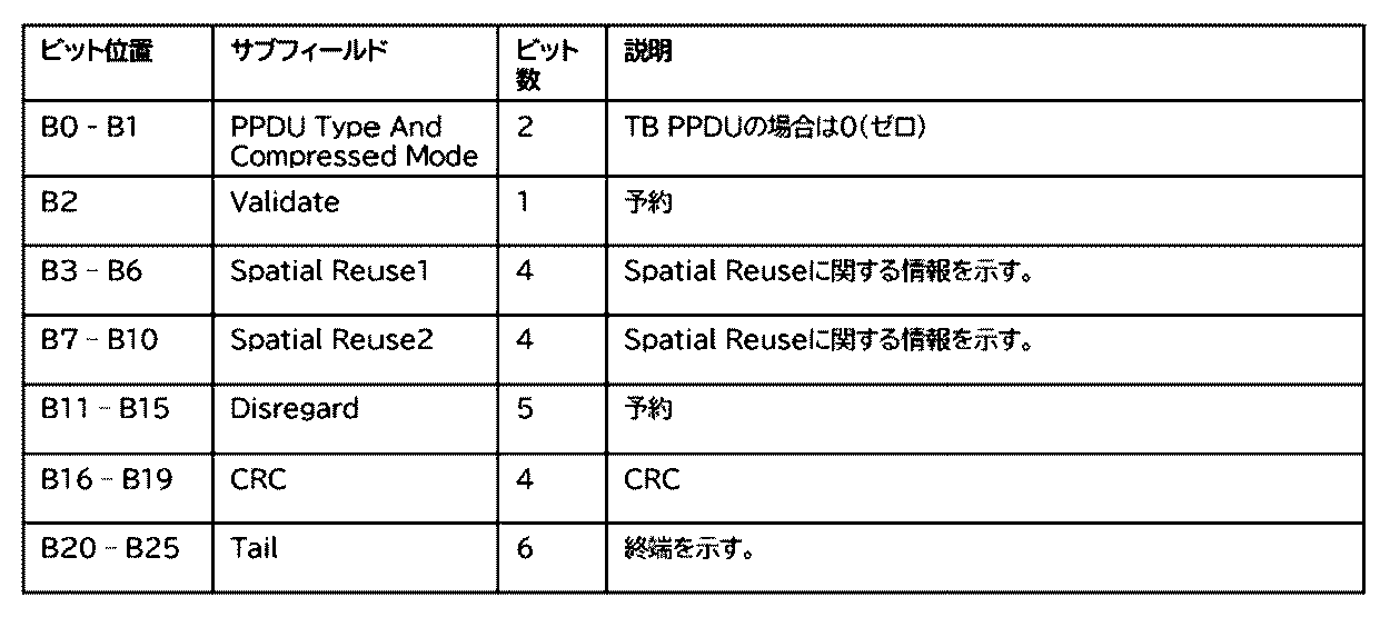
通信装置は、Spatial Reuse1、2の夫々のサブフィールドを用いて、Spatial Reuseに関する情報を示す。
Spatial Reuse1、2の各サブフィールドの値に対応する意味を示す。サブフィールドの値が0の場合は、PSR_DISALLOWという意味であって、これはPSR-basedによるSpatial Reuseの禁止を意味する。また、サブフィールドの値が15の場合は、PSR_AND_NON_SRG_OBSS_PD_PROHIBITEDという意味であって、PSR-based、およびOBSS PD-basedによるSpatial Reuseの禁止を意味する。なお、サブフィールドの値が1~14の場合は、夫々PSR-basedによるSpatial Reuseを実行する装置は、サブフィールドが示すPSRの値に基づいて送信電力の上限を決定する。
(実施形態1)
図4は、本実施形態においてSTA112がAP111に対してSRを許容する通信フレームを送信する場合のタイムシーケンス図である。この図を用いて本実施形態の動作の流れを説明する。
図4は、本実施形態においてSTA112がAP111に対してSRを許容する通信フレームを送信する場合のタイムシーケンス図である。この図を用いて本実施形態の動作の流れを説明する。
ここで各AP、STAの位置関係は、図1に示されているような相対的距離にあるものとする。STA112がAP111宛に送信する通信フレーム401はOBSS PD-based SRを許容する情報、つまりOBSS PD-based SRを許可することを示す情報がPHYヘッダに含まれている。ここではPHYフレームにOBSS PD-based SRを許可することを示す情報が含まれるとしたが、MACフレームに含まれる構成であってもよい。AP121が構築するネットワークに含まれているSTA122は、STA112が送信した通信フレーム401のPHYヘッダから、OBSS PD-based SRが許容されていることを検出し、IEEE802.11規格に従ってSRを利用した通信フレーム402をAP121宛に送信する。
AP111は本来、STA112が送信した通信フレーム401の受信を行いたいのであるが、STA112よりも、OBSSに所属するSTA122の方がAP111に近い距離にある。よって、希望波であるSTA112からの信号と妨害波であるSTA122との信号の強度の比を十分に確保することができない。つまり、AP111においてOBSS干渉を考慮した受信信号電力対干渉および雑音電力の比である受信SINR(Signal-to-Interference plus Noise power Ratio)が不足するため、受信信号を正しく復調することができなくなる。ここでは通信フレーム401のモザイク部分が通信フレーム402と干渉し、正しく受信、復調できなかったものとする。
一方でSTA122が通信フレーム402の送信を開始する前にはSTA112が送信する通信フレーム401に含まれるPHYヘッダを読み取り、さらに他の端末と競合しないためにバックオフ時間を確保している。そのため、AP111においては、STA112が送信した通信フレーム401の少なくともPHYヘッダ部は受信できているため、STA112が送信した通信フレーム401の信号強度やフレーム長などの情報は検出できている。
STA122が送信した通信フレーム402の終了時間が、STA112が送信した通信フレーム401が終了時間よりも長い場合は、STA122が送信している通信フレーム402のAP111における信号強度を検出することができる。また、STA122が送信した通信フレーム402のAP111における信号強度が、STA112が送信した通信フレーム401の信号の強度よりも強い場合には、STA122が送信した通信フレーム402のAP111における信号強度を検出することができる。
STA122がSRを使用して送信した通信フレーム402が、その宛先であるAP121において正しく復調された場合には、STA122に対してAP121からAcknowledgement(Ack)403が送信される。Ack403には宛先アドレスが含まれているため、AP111がこれを傍受できれば、直前にSTA112が送信した通信フレーム401を妨害した信号を送信した機器のアドレス、つまりSTA122の識別情報を検出ことができる。
ここまでの処理により、SRを許容したことにより、AP111はSTA112からの通信フレーム401の受信を正常に完了することはできなかったものの、AP111は3つの情報を得ることができている。1つ目がSTA112から送信される信号の信号強度、2つ目がSTA122から送信される信号の信号強度、3つ目がSTA122のアドレスである。ここでアドレスとはMACアドレスとするが装置を識別できる情報であれば他の情報であってもよい。一方で、AP111に通信フレーム401を送信したSTA112では、これらの情報は得られていない。上記情報がない場合、再び同じ条件でSRを許容した通信フレームをSTA112が送信すると、同一の原因により再度AP111で通信フレームを正しく受信できない可能性が高い。そのためAP111はSRを許容したことによりSTA112からの通信フレームを受信できなかった場合に、上記3つの情報(STA112から送信される信号の信号強度、STA122から送信される信号の信号強度、STA122のアドレス)をSTA112にSR Fail Reportのフレーム404で通知する。ここでは3つの情報としたが、少なくとも1つ以上の情報であってもよいし、3つ以上の情報を通知してもよい。上記3つの情報を取得したSTA112は、AP111で受信できなかった通信フレームを再送信する際にSR Fail Reportとして受け取った情報を基に例えば以下のような対策を実施する。
1.SINRが低くてもAP111で復調できるように通信フレームの変調度(Modulation and Coding Scheme(MCS))を変更する(下げる)。
2.SINRが高くなるように周波数当たりの信号強度を高くする。
3.SRを使用しないと判断し、PHYヘッダ部を変更してSRを禁止する。つまりSRが許可されることを示す通信フレームの送信をやめ、SRを禁止することを示す通信フレームを送信する。
1.SINRが低くてもAP111で復調できるように通信フレームの変調度(Modulation and Coding Scheme(MCS))を変更する(下げる)。
2.SINRが高くなるように周波数当たりの信号強度を高くする。
3.SRを使用しないと判断し、PHYヘッダ部を変更してSRを禁止する。つまりSRが許可されることを示す通信フレームの送信をやめ、SRを禁止することを示す通信フレームを送信する。
AP111におけるSTA122からの通信フレーム402の信号強度が一定以上の大きさである場合は、STA112がSRを許容した通信フレームを送信していても、AP111にはSTA122からの信号強度が強く入力されるため、AP111ではSRを使用した通信フレームを正しく復調できない可能性が高いので、SRを使用しないという判断も可能になる。妨害波を送信する送信元の機器がSTA122であるかどうかは、MACヘッダ部の送信元情報を読み取れば判定可能である。また、PHYヘッダ部のBSS Colorなどの送信元をある程度限定できる情報と、その通信フレームの信号強度から送信元がSTA122である場合と同等な影響をAP111に及ぼすことを推定できる場合にも、SRを使用しないという判断をすることができる。
SR Fail Report404は、AP111がSRを許容した通信フレームの受信に失敗した場合に毎回発行する必要はない。一つの目安として、SRが原因で発生する受信フレームエラーレート(FER)が所定の割合、例えば10%を超えるようであれば、SR Fail Reportを発行する。FERが10%未満程度である場合には、SR Fail Reportを発行せずに従来通りの受信エラーとして処理した方が、通信容量を維持できる。
図5のフローチャート500は、本実施形態においてAP111がSTA112からのSRを許容した通信フレームの受信が正常に完了できず、SR Fail Reportを発行する一連の流れを示すフローチャートである。S501~S507の処理は、例えばAP111の制御部202が、記憶部201に記憶されたプログラムを実行することによって実現される。
まず、AP111とSTA112が無線通信をできるように無線通信接続を確立する。そしてSTA112からのSRを許容した通信フレームの受信を開始する。SRを許容した通信フレームはPHYヘッダ部にSRを許容することが示されているので、通信フレームのPHYヘッダ部はAP111でも正常に受信ができている。ここでAP111はSTA112から送信された通信フレームの信号強度を検出する(S501)。特にAP111はSTA112から送信された通信フレームのAP111における受信信号強度を検出する。
STA122がSRを使用して通信フレームの送信を開始するので、AP111はSTA122からの通信フレームを受信する(S502)。この時、AP111はSTA112からの通信フレームとSTA122からの通信フレームの両方を受信する状態となる。
続いてAP111はSTA112からの通信フレームが復調できなくなったかどうかを判定する(S503)。AP111は継続してSTA112からの通信フレームが復調できているのであれば(S503のno)、従来通りの受信の処理を継続して処理を終了する。
AP111がSTA112からの通信フレームが復調できなくなっている場合(S503のyes)、STA112からの通信フレームのヘッダ部から入手しているフレーム長からSTA112からの通信フレームが終了するまで待機し、その後、STA122からの通信フレームだけが送信されている状態で、STA122からの通信フレームの信号強度を検出する。つまり、AP111はSTA122が送信する通信フレームのAP111での信号強度を検出する(S504)。
STA122から送信される通信フレームの信号が途切れた場合、AP111はSTA122からの通信フレームの送信が終了したものと判断する(S505)。
STA122から送信された通信フレームが、その宛先であるAP121で正しく受信されたのであれば、AP121はSTA122宛にAckを返す。そのAckをAP111は傍受して、STA122のMACアドレスを検出する(S506)。
AP111は、ここまでの一連の処理で得られた情報である、AP111におけるSTA112からの通信フレームの信号強度、STA122からの通信フレームの信号強度、STA122のMACアドレスをSR Fail ReportとしてSTA112に送信する(S507)。
本フローチャートの処理により、APは自装置宛に通信フレームを送信したSTAに対して、通信フレームのエラーを通知することができる。この時、STAがデータを再送する場合に参考となる情報も通知することが可能となる。
図5のフローチャート510はSTA112がAP111からSR Fail Reportを受信した際の処理を示すフローチャートである。本フローチャートの処理は、例えばSTA112の制御部202が、記憶部201に記憶されたプログラムを実行することによって実現される。
STA112はS507でAP111から送信されたSR Fail Reportを受信する(S511)。
STA112はS511で受信したSR Fail Reportに含まれる情報、例えば、AP111におけるSTA112から送信される信号の信号強度、STA122から送信される信号の信号強度、STA122のアドレス等に基づいて、エラーとなった通信フレームを再送するか否か判断する(S512)。再送しないと判断した場合は処理を終了する。
S512で通信フレームを再送すると判断した場合、STA112は通信フレームのMCSを変更して通信フレームを再送する、信号強度を変更して通信フレームを再送する、SRを禁止する旨を示す通信フレームを再送するなど、いずれか1つ以上の調整を行った後に通信フレームを再送する(S513)。つまり、ここでは上述したような
1.SINRが低くてもAP111で復調できるように通信フレームの変調度(Modulation and Coding Scheme(MCS))を変更する(下げる)。
2.SINRが高くなるように周波数当たりの信号強度を高くする。
3.SRを使用しないと判断し、PHYヘッダ部を変更してSRを禁止する。つまりSRが許可されることを示す通信フレームの送信をやめ、SRを禁止することを示す通信フレームを送信する。
1.SINRが低くてもAP111で復調できるように通信フレームの変調度(Modulation and Coding Scheme(MCS))を変更する(下げる)。
2.SINRが高くなるように周波数当たりの信号強度を高くする。
3.SRを使用しないと判断し、PHYヘッダ部を変更してSRを禁止する。つまりSRが許可されることを示す通信フレームの送信をやめ、SRを禁止することを示す通信フレームを送信する。
いずれか1つ以上の処理を行って通信フレームを送信するようにする。例えば、図6A~図6Dに示したフレームの対応するフィールドのパラメータを変更して通信フレームを送信する。
以上のフローチャートの処理により、STAは送信した通信フレームがAPで適切に受信されない場合であっても、受信のエラーが起こらないような最適なパラメータを設定した通信フレームを再送することが可能となる。
(その他の実施形態)
なお上述の実施形態においてはIEEE802.11シリーズに準拠した無線LAN通信の形態に関して説明したが、これに限る物ではない。例えば、ワイヤレスUSB、MBOA、Bluetooth(登録商標)、UWB、ZigBee、NFC等の無線通信媒体を用いて、所定のフレームに適用して実施するようにしてもよい。ここで、MBOAは、Multi Band OFDM Allianceの略である。また、UWBには、ワイヤレスUSB、ワイヤレス1394、WINETなどが含まれる。
なお上述の実施形態においてはIEEE802.11シリーズに準拠した無線LAN通信の形態に関して説明したが、これに限る物ではない。例えば、ワイヤレスUSB、MBOA、Bluetooth(登録商標)、UWB、ZigBee、NFC等の無線通信媒体を用いて、所定のフレームに適用して実施するようにしてもよい。ここで、MBOAは、Multi Band OFDM Allianceの略である。また、UWBには、ワイヤレスUSB、ワイヤレス1394、WINETなどが含まれる。
本発明は、上述の実施形態の1以上の機能を実現するプログラムを、ネットワーク又は記憶媒体を介してシステム又は装置に供給し、そのシステム又は装置のコンピュータにおける1つ以上のプロセッサーがプログラムを読出し実行する処理でも実現可能である。また、1以上の機能を実現する回路(例えば、ASIC)によっても実現可能である。
発明は上記実施形態に制限されるものではなく、発明の精神及び範囲から離脱することなく、様々な変更及び変形が可能である。従って、発明の範囲を公にするために請求項を添付する。
本願は、2023年5月16日提出の日本国特許出願特願2023-081139を基礎として優先権を主張するものであり、その記載内容の全てをここに援用する。
Claims (12)
- IEEE802.11に準拠した通信を実行する通信装置であって、
第一の他の通信装置から送信されるSpecial Reuse (SR)を許可することを示す情報を含む第一の通信フレームの少なくとも一部を受信する第一の受信手段と、
第二の他の通信装置から送信される、前記通信フレームの受信を妨害する第二の通信フレームを検出する検出手段と、
前記第一の受信手段で受信した信号の信号強度と、前記検出手段で検出した第二の通信フレームの信号強度とに基づいて、前記第一の通信装置に前記通信フレームの受信のエラーを通知する通知手段と、
を有することを特徴とする通信装置。 - 前記第二の他の装置の識別情報を取得する取得手段をさらに有し、前記通知手段は、前記識別情報を前記第一の通信装置にさらに通知することを特徴とする請求項1に記載の通信装置。
- 前記取得手段は、前記第二の通信フレームに対して第三の通信装置から送信されるAcknowledgement(Ack)を受信することにより、前記第二の他の装置の識別情報を取得することを特徴とする請求項2に記載の通信装置。
- 前記識別情報はMACアドレスであることを特徴とする請求項2または請求項3に記載の通信装置。
- 前記通知手段は、フレームエラーレートが所定の割合以上であると、前記エラーを通知し、フレームエラーレートが所定の割合以上でなければ、前記エラーを通知しないことを特徴とする請求項1から請求項4のいずれか1項に記載の通信装置。
- 前記通知手段は、前記第一の受信手段で受信した信号の信号強度と、前記検出手段で検出した第二の通信フレームの信号強度とを前記第一の通信装置に通知することを特徴とする請求項1から請求項5のいずれか1項に記載の通信装置。
- 前記通知手段で通知された前記第一の受信手段で受信した信号の信号強度と、前記検出手段で検出した第二の通信フレームの信号強度とに基づいて、前記第一の通信装置は通信フレームを再送することを特徴とする請求項1から請求項6のいずれか1項に記載の通信装置。
- 前記通知手段で通知された前記第一の受信手段で受信した信号の信号強度と、前記検出手段で検出した第二の通信フレームの信号強度とに基づいて、前記第一の通信装置はModulation and Coding Scheme (MCS)を変更して通信フレームを再送することを特徴とする請求項1から請求項7のいずれか1項に記載の通信装置。
- 前記通知手段で通知された前記第一の受信手段で受信した信号の信号強度と、前記検出手段で検出した第二の通信フレームの信号強度とに基づいて、前記第一の通信装置は信号強度を変更して通信フレームを再送することを特徴とする請求項1から請求項8のいずれか1項に記載の通信装置。
- 前記通知手段で通知された前記第一の受信手段で受信した信号の信号強度と、前記検出手段で検出した第二の通信フレームの信号強度とに基づいて、前記第一の通信装置はSRを禁止することを示す通信フレームを再送することを特徴とする請求項1から請求項9のいずれか1項に記載の通信装置。
- IEEE802.11に準拠した通信を実行する通信装置が実行する制御方法であって、
前記制御方法は
第一の他の通信装置から送信されるSpecial Reuse (SR)を許可することを示す情報を含む第一の通信フレームの少なくとも一部を受信する第一の受信工程と、
第二の他の通信装置から送信される、前記通信フレームの受信を妨害する第二の通信フレームを検出する検出工程と、
前記第一の受信手段で受信した信号の信号強度と、前記検出手段で検出した第二の通信フレームの信号強度とに基づいて、前記第一の通信装置に前記通信フレームの受信のエラーを通知する通知工程と、
を有することを特徴とする制御方法。 - コンピュータを、請求項1から10の何れか1つの構成に記載の通信装置として機能させるためのプログラム。
Priority Applications (1)
| Application Number | Priority Date | Filing Date | Title |
|---|---|---|---|
| US19/388,395 US20260074835A1 (en) | 2023-05-16 | 2025-11-13 | Communication apparatus, information processing apparatus, control method, and storage medium |
Applications Claiming Priority (2)
| Application Number | Priority Date | Filing Date | Title |
|---|---|---|---|
| JP2023081139A JP2024165204A (ja) | 2023-05-16 | 2023-05-16 | 通信装置、情報処理装置、制御方法、及び、プログラム |
| JP2023-081139 | 2023-05-16 |
Related Child Applications (1)
| Application Number | Title | Priority Date | Filing Date |
|---|---|---|---|
| US19/388,395 Continuation US20260074835A1 (en) | 2023-05-16 | 2025-11-13 | Communication apparatus, information processing apparatus, control method, and storage medium |
Publications (1)
| Publication Number | Publication Date |
|---|---|
| WO2024237010A1 true WO2024237010A1 (ja) | 2024-11-21 |
Family
ID=93518979
Family Applications (1)
| Application Number | Title | Priority Date | Filing Date |
|---|---|---|---|
| PCT/JP2024/015518 Ceased WO2024237010A1 (ja) | 2023-05-16 | 2024-04-19 | 通信装置、情報処理装置、制御方法、及び、プログラム |
Country Status (3)
| Country | Link |
|---|---|
| US (1) | US20260074835A1 (ja) |
| JP (1) | JP2024165204A (ja) |
| WO (1) | WO2024237010A1 (ja) |
Citations (2)
| Publication number | Priority date | Publication date | Assignee | Title |
|---|---|---|---|---|
| WO2019167439A1 (ja) * | 2018-02-28 | 2019-09-06 | パナソニック インテレクチュアル プロパティ コーポレーション オブ アメリカ | 無線通信装置及び無線通信方法 |
| WO2022093984A1 (en) * | 2020-11-02 | 2022-05-05 | Qualcomm Incorporated | Selective spatial reuse transmissions |
-
2023
- 2023-05-16 JP JP2023081139A patent/JP2024165204A/ja active Pending
-
2024
- 2024-04-19 WO PCT/JP2024/015518 patent/WO2024237010A1/ja not_active Ceased
-
2025
- 2025-11-13 US US19/388,395 patent/US20260074835A1/en active Pending
Patent Citations (2)
| Publication number | Priority date | Publication date | Assignee | Title |
|---|---|---|---|---|
| WO2019167439A1 (ja) * | 2018-02-28 | 2019-09-06 | パナソニック インテレクチュアル プロパティ コーポレーション オブ アメリカ | 無線通信装置及び無線通信方法 |
| WO2022093984A1 (en) * | 2020-11-02 | 2022-05-05 | Qualcomm Incorporated | Selective spatial reuse transmissions |
Also Published As
| Publication number | Publication date |
|---|---|
| JP2024165204A (ja) | 2024-11-28 |
| US20260074835A1 (en) | 2026-03-12 |
Similar Documents
| Publication | Publication Date | Title |
|---|---|---|
| US20250202669A1 (en) | Bss-color enhanced transmission in wlans (bss-cet) | |
| JP7534295B2 (ja) | ワイヤレスネットワークにおけるharqのための方法および装置 | |
| US9918342B2 (en) | Method and device for transmitting/receiving frame in accordance with bandwidth thereof in WLAN system | |
| KR101832777B1 (ko) | 무선 랜 시스템에서의 채널 액세스 방법 및 이를 수행하는 장치 | |
| CN116134952A (zh) | 使用多个链路的无线通信方法和使用该方法的无线通信终端 | |
| JP7635057B2 (ja) | 通信装置、通信装置の制御方法、およびプログラム | |
| WO2024092736A1 (en) | Multi-primary channel access | |
| US20250016836A1 (en) | Communication device, communication method, and storage medium | |
| US11510095B2 (en) | Method for transmitting or receiving frame in wireless LAN system and apparatus therefor | |
| US20250261233A1 (en) | Spatial reuse transmissions in wireless local area networks | |
| US12615677B2 (en) | Communication apparatus, communication control method, communication method, and computer-readable storage medium | |
| EP3694288B1 (en) | Terminal and communication method | |
| WO2024237010A1 (ja) | 通信装置、情報処理装置、制御方法、及び、プログラム | |
| US20250226897A1 (en) | Communication apparatus, communication method, and storage medium | |
| US20240179765A1 (en) | Wireless communication apparatus, communication control method, and non-transitory computer-readable storage medium | |
| US20250274888A1 (en) | Communication apparatus, control method, and computer-readable storage medium | |
| US12224862B2 (en) | Communication apparatus, control method, and storage medium | |
| WO2023210335A1 (ja) | 通信装置、通信方法、およびプログラム | |
| WO2024004588A1 (ja) | 通信装置、制御方法、およびプログラム |
Legal Events
| Date | Code | Title | Description |
|---|---|---|---|
| 121 | Ep: the epo has been informed by wipo that ep was designated in this application |
Ref document number: 24806964 Country of ref document: EP Kind code of ref document: A1 |
|
| NENP | Non-entry into the national phase |
Ref country code: DE |