WO2024236723A1 - 油圧作動装置 - Google Patents
油圧作動装置 Download PDFInfo
- Publication number
- WO2024236723A1 WO2024236723A1 PCT/JP2023/018228 JP2023018228W WO2024236723A1 WO 2024236723 A1 WO2024236723 A1 WO 2024236723A1 JP 2023018228 W JP2023018228 W JP 2023018228W WO 2024236723 A1 WO2024236723 A1 WO 2024236723A1
- Authority
- WO
- WIPO (PCT)
- Prior art keywords
- oil
- shaft portion
- oil passage
- shaft
- operating
- Prior art date
- Legal status (The legal status is an assumption and is not a legal conclusion. Google has not performed a legal analysis and makes no representation as to the accuracy of the status listed.)
- Ceased
Links
Images


Classifications
-
- B—PERFORMING OPERATIONS; TRANSPORTING
- B23—MACHINE TOOLS; METAL-WORKING NOT OTHERWISE PROVIDED FOR
- B23D—PLANING; SLOTTING; SHEARING; BROACHING; SAWING; FILING; SCRAPING; LIKE OPERATIONS FOR WORKING METAL BY REMOVING MATERIAL, NOT OTHERWISE PROVIDED FOR
- B23D17/00—Shearing machines or shearing devices cutting by blades pivoted on a single axis
- B23D17/02—Shearing machines or shearing devices cutting by blades pivoted on a single axis characterised by drives or gearings therefor
- B23D17/06—Shearing machines or shearing devices cutting by blades pivoted on a single axis characterised by drives or gearings therefor actuated by fluid or gas pressure
-
- B—PERFORMING OPERATIONS; TRANSPORTING
- B25—HAND TOOLS; PORTABLE POWER-DRIVEN TOOLS; MANIPULATORS
- B25F—COMBINATION OR MULTI-PURPOSE TOOLS NOT OTHERWISE PROVIDED FOR; DETAILS OR COMPONENTS OF PORTABLE POWER-DRIVEN TOOLS NOT PARTICULARLY RELATED TO THE OPERATIONS PERFORMED AND NOT OTHERWISE PROVIDED FOR
- B25F5/00—Details or components of portable power-driven tools not particularly related to the operations performed and not otherwise provided for
-
- B—PERFORMING OPERATIONS; TRANSPORTING
- B23—MACHINE TOOLS; METAL-WORKING NOT OTHERWISE PROVIDED FOR
- B23D—PLANING; SLOTTING; SHEARING; BROACHING; SAWING; FILING; SCRAPING; LIKE OPERATIONS FOR WORKING METAL BY REMOVING MATERIAL, NOT OTHERWISE PROVIDED FOR
- B23D29/00—Hand-held metal-shearing or metal-cutting devices
- B23D29/002—Hand-held metal-shearing or metal-cutting devices for cutting wire or the like
Definitions
- This disclosure relates to a hydraulically actuated device.
- Portable hydraulic actuators have been used for rescue purposes for some time, and one example is described in, for example, Patent Document 1.
- the hydraulic actuator disclosed in Patent Document 1 is composed of a hydraulic generating unit having a battery, an electric motor powered by the battery, and a hydraulic pump driven by the electric motor, and a head unit that is detachable from the hydraulic generating unit and has a tip tool driven by pressure oil generated by the hydraulic generating unit.
- Various types of tip tools such as cutters and spreaders, are available for installation on the head unit, and a wide variety of tasks can be handled by replacing the head unit.
- By making the hydraulic generating unit and the head unit separable portability can be improved and the burden on workers at the site can be reduced.
- a spool valve when the pressurized oil generated by the hydraulic pump is sent to the tool tip or when the oil is returned from the tool tip to the hydraulic pump, the path of the pressurized oil or return oil in the oil passage is switched by a spool valve (see, for example, Patent Document 2).
- the spool valve is arranged so that it can slide in a direction perpendicular to the piston rod.
- a cylindrical grip handle that is held by the operator's hand is attached to the outside of the casing in parallel with the piston rod.
- the grip handle is rotatable around the axis of the grip handle.
- multiple cam mechanisms are provided between the spool valve and the grip handle.
- the operator can operate the operating part with the hands and fingers of the operator gripping the handle without releasing his or her hands from the handle or grip part.
- the handle In the spool valves of conventional hydraulic actuators as disclosed in Patent Documents 2 and 3, the handle extends in a direction perpendicular to the forward and backward movement of one spool valve, and the handle is rotatable about its axis. This requires a large installation space for the handle, which results in a large hydraulic actuator, and increases the mass and cost of the hydraulic actuator.
- the present disclosure has been made in consideration of these points, and aims to provide a hydraulically actuated device that does not require a complex mechanism for switching the paths of pressurized oil and return oil in the oil passages, and that can easily switch a set of valves simply by turning a change lever left and right, thereby making it small, inexpensive, and of a simple configuration.
- the hydraulic actuator of the present disclosure comprises a hydraulic pump that generates pressurized oil, a tool that is actuated by the pressurized oil generated by the hydraulic pump, an oil passage that sends the pressurized oil generated by the hydraulic pump to the tool and returns return oil from the tool to the pressurized oil pump, and a switching unit that is provided in the oil passage and switches the path of at least one of the pressurized oil and the return oil, the switching unit having an operating part, and a first shaft part and a second shaft part that move forward and backward when the operating part is rotated, and the first shaft part and the second shaft part move forward and backward alternately in a direction perpendicular to the direction in which the operating part is rotated when the operating part is rotated, thereby switching the path in the oil passage.
- the switching unit may have a conversion member that converts the rotational motion of the actuating part into forward and backward motion of the first shaft part and the second shaft part.
- the actuating part, the conversion member, and the phase adjustment member are adapted to rotate in the same phase, and grooves are provided on the outer peripheral surfaces of the first shaft part and the second shaft part, extending in a direction inclined with respect to the circumferential direction and the forward/backward direction of the first shaft part and the second shaft part, respectively, and a fixing member provided in a fixed position may be inserted into each of the grooves.
- the first shaft portion and the second shaft portion of the switching portion may be provided with a seal member extending circumferentially around the first shaft portion and the second shaft portion, and when the first shaft portion and the second shaft portion move forward and backward as the operating portion is rotated, the position of the seal member changes, thereby switching the path in the oil passage.
- an insertion hole into which the shaft portion of the switching unit is inserted is formed in the main body of the hydraulic actuator, and an oil passage extending circumferentially of the insertion hole is provided in the peripheral wall of the insertion hole, and when the shaft portion advances or retreats as the actuating portion is rotated, the oil passage that was blocked by the shaft portion is opened, or the oil passage is blocked by the shaft portion, thereby switching the path in the oil passage.
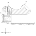
- FIG. 1 is a front view of a cutting device according to an embodiment of the present disclosure.
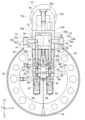
- 2 is a side cross-sectional view showing an internal configuration of the cutting device shown in FIG. 1 as viewed from the side.
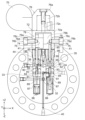
- 3 is an enlarged side cross-sectional view showing a part of the internal configuration of the cutting device shown in FIG. 2.
- 2 is a side cross-sectional view showing an internal configuration of an operating handle of the cutting device shown in FIG. 1.
- 2 is an exploded perspective view showing the configuration of a handle support portion and a reciprocating member in the cutting device shown in FIG. 1.
- 2 is a front view showing a configuration of a reciprocating member in the cutting device shown in FIG. 1 .
- 2 is a diagram showing an internal configuration of a pressure oil supply mechanism in the cutting device shown in FIG.
- FIG. 2 is a diagram showing an internal configuration of a pressure oil supply mechanism in the cutting device shown in FIG. 1 when the operating handle is in a neutral position.
- FIG. 2 is a diagram showing an internal configuration of a pressure oil supply mechanism when the operating handle is in a reverse position in the cutting device shown in FIG. 1 .
- FIG. 2 is an exploded perspective view of a flow path adjustment valve in the pressure oil supply mechanism of the cutting device shown in FIG. 1 .
- 4 is a configuration diagram showing a state in which the through hole of the second seal plate is not sealed by the seal pin in the pressure oil supply mechanism of the cutting device shown in FIG. 1 .
- FIG. 2 is a configuration diagram showing a state in which a through hole of a second seal plate is sealed by a seal pin in the pressure oil supply mechanism of the cutting device shown in FIG. 1 .
- FIG. 1 is a configuration diagram showing a state in which a through hole of a second seal plate is sealed by a seal pin in the pressure oil supply mechanism of the cutting device shown
- the cutting device 10 (hydraulic actuator) according to this embodiment is used for rescue and other applications, and is capable of cutting round bars such as reinforcing bars with a cutting section.
- Figures 1 to 11 are diagrams showing the cutting device 10 according to this embodiment.
- Figures 2 to 8 in order to make it easier to see the oil passages for pressure oil and return oil, the flow path adjustment valve, etc., hatching to show cross sections around these oil passages and flow path adjustment valves, etc. is omitted.
- an XYZ orthogonal coordinate system is set in which the length direction of the cutting device 10 (hydraulic actuator) according to this embodiment is the Y-axis direction, the length direction of the protruding portion 76b when placed in the cutting device 10 (hydraulic actuator) is the X-axis direction, and the direction perpendicular to the Y-axis direction and the X-axis direction is the Z-axis direction, and reference is made as appropriate.
- the cutting device 10 includes a motor 20 such as an electric motor, a battery 22 consisting of a secondary battery such as a lithium ion battery or a nickel-metal hydride battery, a cutting unit 50 for cutting round bars such as reinforcing bars, and an operating unit 21 for operating the cutting unit 50.
- the cutting unit 50 has a pair of cutting members 64, 66, each of which is rotatable about an axis 68.
- the round bars such as reinforcing bars between the pair of cutting members 64, 66 are cut by rotating the cutting members 64, 66 in a direction that brings them closer to each other about the axis 68.
- an operating handle 70 is attached to the operating unit 21, and the operator can adjust the rotation direction of each cutting member 64, 66 around the axis 68 by operating this operating handle 70.
- the operating handle 70 is rod-shaped, and when the operator grips the operating handle 70 with his/her hand and rotates it in the forward or reverse direction from the initial position (for example, 30 degrees forward and 30 degrees reverse), each cutting member 64, 66 rotates in a direction approaching or moving away from each other around the axis 68.
- this operating handle 70 returns to its initial position.
- a rotating shaft 24 is attached to the motor 20, and the rotating shaft 24 attached to the motor 20 is rotated by supplying power from a battery 22 to the motor 20.
- An eccentric member 25 is attached to the tip of the rotating shaft 24.
- the eccentric member 25 is eccentric with respect to the axis of the rotating shaft 24, and a bearing such as a needle roller bearing is attached to the outer circumferential surface of the eccentric member 25.
- the operating section 21 has a piston 26 arranged around the eccentric member 25, an oil chamber 28, and a pressure oil supply mechanism 30 that sends pressure oil from the oil chamber 28 to the cutting section 50 and returns pressure oil from the cutting section 50 to the oil chamber 28.
- the piston 26 moves up and down as the eccentric member 25 rotates.
- the piston 26 is constantly pressed against the outer circumferential surface of the bearing by a spring (not shown). Therefore, when the rotating shaft 24 is rotated by the motor 20, the eccentric member 25 and the bearing rotate eccentrically about the axis of the rotating shaft 24, causing the piston 26 to move up and down, and pressure oil is sent from the oil chamber 28 to the pressure oil supply mechanism 30, and pressure oil is supplied from the pressure oil supply mechanism 30 to the cutting section 50, causing the cutting section 50 to operate.
- the configuration of the cutting unit 50 will be described with reference to Figures 1 and 2.
- the cutting unit 50 has a pair of cutting members 64, 66, each of which can rotate around an axis 68, a base member 59, and a piston member 52 to which the base member 59 is attached at its tip.
- a blade portion 64b for cutting a round bar is provided at a location of the cutting member 64 facing the cutting member 66.
- a blade portion 66b for cutting a round bar is also provided at a location of the cutting member 66 facing the cutting member 64.
- the cutting member 64 and the base member 59 are connected by a connecting member 60.
- the cutting member 64 is connected to the connecting member 60 so as to be rotatable relative to the connecting member 60 around an axis 64a provided at the base end portion.
- the connecting member 60 is connected to the base member 59 so as to be rotatable relative to the base member 59 around an axis 60a provided at the base end portion.
- the cutting member 66 and the base member 59 are connected by a connecting member 62. More specifically, the cutting member 66 is connected to the connecting member 62 so as to be rotatable relative to the connecting member 62 around an axis 66a provided at the base end portion of the cutting member 66.
- the connecting member 62 is also connected to the base member 59 so as to be rotatable relative to the base member 59 around an axis 62a provided at the base end portion of the cutting member 66.
- the cutting members 64, 66 rotate around the axis 68 in a direction approaching each other, so that a round bar such as a reinforcing bar sandwiched between the cutting members 64, 66 is cut.
- a round bar such as rebar sandwiched between the cutting members 64, 66
- the base member 59 moves to the right in FIGS. 1 and 2
- the base end portions of the cutting members 64, 66 are pulled by the connecting members 60, 62 rotatably connected to the tip portions of the base member 59, and the cutting members 64, 66 rotate around the axis 68 in directions away from each other (i.e., in the opposite direction to the arrows shown in FIG. 1).
- the operating unit 21 that operates the cutting unit 50 has a pressure oil supply mechanism 30 that sends pressure oil from the oil chamber 28 to the cutting unit 50 and returns pressure oil from the cutting unit 50 to the oil chamber 28.
- the operating unit 21 is also provided with an operating handle 70, and the operator can adjust the flow path of the pressure oil and return oil by the pressure oil supply mechanism 30 by operating this operating handle 70. This allows the operator to adjust the rotation direction of each cutting member 64, 66 around the axis 68 by operating this operating handle 70. In this embodiment, when the operator releases the operating handle 70, the operating handle 70 returns to the initial position, in which case each cutting member 64, 66 stops.
- the details of the configuration of the pressure oil supply mechanism 30, the operating handle 70, and the two flow path adjustment valves 80 provided in the pressure oil supply mechanism 30 will be described below.
- the configuration of the operating handle 70 will be explained using Figures 3 and 4.
- the operating handle 70 can be rotated in both the forward and reverse directions from the initial position.
- Such an operating handle 70 is supported by a handle support part 72 (operating part) attached to the operating part 21.
- the operating handle 70 is also rotatable relative to the handle support 72.
- the rotation angle of the operating handle 70 from its initial position is limited to a predetermined range. After rotating the operating handle 70 from its initial position, when the operator releases his or her hand from the operating handle 70, the operating handle 70 returns to its initial position.
- a phase adjustment member 76 is attached to the operating handle 70.
- the axis of the rotation shaft of the operating handle 70 is the same as the axis of the phase adjustment member 76. Therefore, when an operator grips the operating handle 70 with his or her hand and rotates it from the initial position, the phase adjustment member 76 also rotates in sync.
- the base portion 76a is provided inside the operating handle 70, and when the operating handle 70 rotates, this base portion 76a also rotates integrally.
- a pair of left and right first and second pushing parts 78a and 78b that constitute a reciprocating member 78 are disposed inside the handle support part 72, and a base part 76a of a phase adjustment member 76 is connected to the reciprocating member 78.
- a pair of left and right protruding parts 76b, which will be described later, are connected to the handle support part 72.
- the handle support part 72 is a member shaped in such a way that a cylindrical member 72a and a tubular member 72b are connected at their flat surfaces.
- the cylindrical member 72a has a larger diameter than the tubular member 72b.
- a recess capable of accommodating a reciprocating member 78 is formed on the end face of the cylindrical member 72a that is not connected to the tubular member 72b.
- the diameter of the recess formed in the cylindrical member 72a of the handle support part 72 is designed to be larger than the diameter of the tubular member 72b.
- the through hole 72c formed in the tubular member 72b penetrates all the way to the cylindrical member 72a, and the central axes of the cylindrical member 72a and the cylindrical member 72b coincide.
- the diameter of the through hole 72c is designed to be slightly larger than the diameter of the base portion 76a.
- the base portion 76a is inserted into the handle support portion 72 from the cylindrical member 72b side.
- Two oval stopper grooves 74 of the same thickness are formed in the cylindrical member 72a of the handle support part 72 and extend along its circumferential direction.
- the two stopper grooves 74 are each formed in the central part of the handle support part 72, and are formed so as to be 180 degrees rotationally symmetrical on the handle support part 72.
- the length of each stopper groove 74 is formed so as to be 1/4 of the shortest straight line length on the circumferential surface of the handle support part 72 or a length close to that.
- Two protrusions 76b (fixed members) are inserted into the stopper grooves 74. Therefore, the rotation angle of the operating handle 70 and the reciprocating member 78 is limited within a predetermined range. For example, the rotation angle of the operating handle 70 and the reciprocating member 78 is limited to 45 degrees or a range close to that.
- the reciprocating member 78 is formed by a first pushing portion 78a on the left side and a second pushing portion 78b on the right side.
- the first pushing portion 78a and the second pushing portion 78b are each semi-cylindrical members.
- the reciprocating member 78 is formed by abutting the first pushing portion 78a and the second pushing portion 78b on flat surfaces that face the semi-circumferential surfaces of the first pushing portion 78a and the second pushing portion 78b.
- first pushing portion 78a and the second pushing portion 78b Furthermore, on the outer peripheral surfaces of the first pushing portion 78a and the second pushing portion 78b, there are formed lead grooves 75 of the same thickness and oval shape that extend in directions inclined with respect to the circumferential direction and the forward/backward direction of the semi-circumferential surfaces of the first pushing portion 78a and the second pushing portion 78b.
- the lead groove 75 is formed in the center of the circumferential surface of the first pushing portion 78a and the second pushing portion 78b or in its vicinity (specifically, slightly on the -Z direction side from the center of the first pushing portion 78a and the second pushing portion 78b), and is formed symmetrically with respect to a plane facing the semi-circumferential surface of the first pushing portion 78a and the second pushing portion 78b.
- the width of the lead groove 75 is slightly smaller than the width of the stopper groove 74.
- the end of the stopper groove 74 and the lead groove 75 on the left side of Figures 6 to 8 on the front side (+Y axis direction) is defined as the first left end
- the end of the stopper groove 74 and the lead groove 75 on the rear side (-Y axis direction) is defined as the second left end
- the ends of the right stopper groove 74 and lead groove 75 on the near side (+Y axis direction) are defined as the third right end
- the ends of the stopper groove 74 and lead groove 75 on the far side (-Y axis direction) are defined as the fourth right end.
- the lead groove 75 is formed to extend in a direction inclined with respect to the circumferential direction and the forward/backward direction of the semi-circumferential surfaces of the first pushing portion 78a and the second pushing portion 78b. Therefore, in Figures 6 to 8, the lead groove 75 is formed to rise from the near side (+Y axis direction) of the first pushing portion 78a and the second pushing portion 78b toward the far side (-Y axis direction).
- a groove 91a is formed on the outer peripheral surface of the first pushing portion 78a or the second pushing portion 78b, into which a slender cylindrical positioning pin 90 is fitted.
- a groove 91b is formed on the inner peripheral surface of the cylindrical member 72a of the handle support portion 72, into which the positioning pin 90 is fitted.
- Such a positioning pin 90 makes it possible to prevent the circumferential positions of the first pushing portion 78a and the second pushing portion 78b from shifting from the handle support portion 72.
- the handle support portion 72 and the reciprocating member 78 can be treated as a single assembly member, and the handle support portion 72 and the reciprocating member 78 can be rotated simultaneously and in the same direction.
- the body portion 76c of the left protrusion portion 76b is located at the first left end portion, which is the end portion on the front side (+Y axis direction) of the left stopper groove 74.
- the tip portion 76d of the left protrusion portion 76b is also located at the first left end portion, which is the end portion on the front side (+Y axis direction) of the left stopper groove 74.
- the body portion 76c of the right protrusion portion 76b is located at the fourth right end portion, which is the end portion on the rear side (-Y axis direction) of the right stopper groove 74.
- the tip portion 76d of the right protrusion portion 76b is also located at the fourth right end portion, which is the end portion on the rear side (-Y axis direction) of the right stopper groove 74.
- the body portion 76c of the left protrusion portion 76b is located at the second left end portion, which is the end portion on the rear side (-Y axis direction) of the left stopper groove 74.
- the tip portion 76d of the left protrusion portion 76b is also located at the second left end portion, which is the end portion on the rear side (-Y axis direction) of the left stopper groove 74.
- the body portion 76c of the right protrusion portion 76b is located at the third right end portion, which is the end portion on the front side (+Y axis direction) of the right stopper groove 74.
- the tip portion 76d of the right protrusion portion 76b is also located at the third right end portion, which is the end portion on the front side (+Y axis direction) of the right stopper groove 74.
- the protrusion 76b is a member that is fixed in position to the handle support portion 72.
- the protrusion 76b is a bolt-shaped member, and the diameter of the tip portion 76d of the protrusion 76b is slightly shorter than the thickness of the lead groove 75. This makes it possible to insert the tip portion 76d of the protrusion 76b into the lead groove 75.
- the tip portion 76d of the protrusion 76b is stored in the lead groove 75, it is possible to restrict the movement of the tip portion 76d of the protrusion 76b in the direction of the thickness of the lead groove 75.
- the diameter of the body 76c of the protruding portion 76b is slightly smaller than the width of the stopper groove 74. This makes it possible to insert the body 76c of the protruding portion 76b, which will be described later, into the stopper groove 74. When the body 76c of the protruding portion 76b is stored in the stopper groove 74, the movement of the body 76c of the protruding portion 76b in the width direction of the stopper groove 74 can be restricted.
- the protruding portion 76b is connected perpendicularly to the central axis of the handle support portion 72.
- the tip portions 76d of the two protruding portions 76b are inserted into the lead grooves 75 of the first pushing portion 78a and the second pushing portion 78b, respectively. Therefore, when the phase adjustment member 76 rotates, the first pushing portion 78a and the second pushing portion 78b also rotate, and the tip portions 76d of the protruding portions 76b inserted into the lead grooves 75 guide the rotation of the first pushing portion 78a and the second pushing portion 78b.
- the lead groove 75 slides guided by the tip part 76d of the protrusion part 76b due to the rotation of the first and second pushing parts 78a and 78b.
- the stopper groove 74 also restricts the tip part 76d of the protrusion part 76b from further sliding in the same direction. Then, the reciprocating member 78 moves up and down alternately as the lead groove 75 is guided by the tip part 76d of the protrusion part 76b. As a result, the first and second pushing parts 78a and 78b move up and down.
- the phase adjustment member 76 rotates in the counterclockwise direction in Figs. 6 to 8.
- the first pushing portion 78a guided by the left protruding portion 76b of the two protruding portions 76b slides down
- the second pushing portion 78b guided by the right protruding portion 76b slides up.
- the left reciprocating member 78 in Fig. 8 is pushed by the protruding portion 76b and descends from the neutral position, while the right reciprocating member 78 rises from the neutral position.
- Such positions of the reciprocating members 78 are referred to as reverse positions.
- the two protruding parts 76b (fixed members) convert the rotational movement of the operating part into the forward and backward movement of the first pushing part 78a and the second pushing part 78b.
- the cutting section 50 has a main body 56 in which an internal space in which pressure oil is stored is formed.
- a partition member 54 is provided inside the main body 56 to partition the internal space formed inside the main body 56 into two regions.
- the end of the piston member 52 is connected to the partition member 54.
- the region to the right of the partition member 54 in FIG. 2 is a forward oil chamber
- the region to the left of the partition member 54 in FIG. 2 is a reverse oil chamber 58.
- the volume of the forward oil chamber is 0 in FIG. 2
- a forward oil chamber is formed between the main body 56 and the partition member 54.
- the pressurized oil supply mechanism 30 is provided with a plurality of oil passages 32, 33, 34, 35, 36, 37, 38, 39, 40 for sending pressurized oil from the oil chamber 28 to the cutting section 50 and returning oil from the cutting section 50 to the oil chamber 28.
- the pressurized oil supply mechanism 30 also has two flow path adjustment valves 80. These two flow path adjustment valves 80 adjust which flow path the pressurized oil sent from the oil chamber 28 to the cutting section 50 and the return oil returned from the cutting section 50 to the oil chamber 28 will pass through.
- the two flow path adjustment valves 80 are each operated by the operating handle 70. Specifically, each flow path adjustment valve 80 is operated by the up and down movement of each reciprocating member 78.
- the first oil passage 32 is connected to the oil chamber 28, and the second oil passage 33 is connected to the first oil passage 32. Between the first oil passage 32 and the second oil passage 33, a first seal plate 81 (described later) of the left flow path adjustment valve 80 is provided.
- the fourth oil passage 35 is connected to the third oil passage 34.
- the sixth oil passage 37 is connected to a forward oil chamber in an area to the right of the partition member 54 in FIG. 2 in the internal space formed inside the main body 56.
- a fifth oil passage 36 is provided around the spool 86 (described later) of the left flow path adjustment valve 80.
- a seventh oil passage 38 is provided around the spool 86 of the right flow path adjustment valve 80, and this seventh oil passage 38 is connected to the third oil passage 34 via a second seal plate 82 of the right flow path adjustment valve 80.
- the first oil passage 32 is connected to the flow passage 51a of the rod-shaped member 51.
- a first seal plate 81 (described later) of the right-side flow passage adjustment valve 80 is provided between the first oil passage 32 and the third oil passage 34.
- a seventh oil passage 38 is provided around a spool 86 (described later) of the right-side flow passage adjustment valve 80.
- a drain pipe 44 is provided to return pressurized oil to the oil chamber 28, and this drain pipe 44 is connected to the eighth oil passage 39.
- the eighth oil passage 39 is connected to the fifth oil passage 36 and the seventh oil passage 38, respectively.
- each flow path adjustment valve 80 has a first seal plate 81, a second seal plate 82, a valve seat 83 provided between the first seal plate 81 and the second seal plate 82, a seal pin 84 (seal member) provided inside the valve seat 83, an operating pin 85 attached to the seal pin 84, and a spool 86 through which the operating pin 85 penetrates.
- the spool 86 is inserted into the cutting section 50 through an insertion hole 41 formed in the cutting section 50.
- each of the two spools 86 is disposed opposite one end of the first pushing section 78a and one end of the second pushing section 78b, respectively, and one end of the first pushing section 78a and one end of the second pushing section 78b presses one end of the operating pin 85 or separates from it, thereby enabling the spools to move forward and backward.
- the valve seat 83 is omitted in order to make the seal pin 84 easier to see. More specifically, as shown in FIG. 10 and FIG. 11, the seal pin 84 has a cylindrical portion 84a and a spherical end surface 84b provided at one end of the cylindrical portion 84a (specifically, the end on the second seal plate 82 side).
- the actuation pin 85 has a first cylindrical portion 85a and a second cylindrical portion 85b having a larger diameter than the first cylindrical portion 85a, and the tip of the first cylindrical portion 85a is attached to the spherical end surface 84b of the seal pin 84.
- the first seal plate 81 has a through hole 81a with a uniform diameter.
- the diameter of the through hole 81a is approximately the same as the diameter of the cylindrical portion 84a of the seal pin 84. Therefore, when the cylindrical portion 84a of the seal pin 84 enters the through hole 81a of the first seal plate 81, the through hole 81a of the first seal plate 81 is sealed by the seal pin 84.
- the second seal plate 82 has a through hole consisting of a first through hole 82a and a second through hole 82b.
- the diameter of the second through hole 82b is larger than the diameter of the first through hole 82a.
- the diameter of the first through hole 82a is smaller than the diameter of the cylindrical portion 84a of the seal pin 84.
- the diameter of the second through hole 82b is larger than the diameter of the cylindrical portion 84a of the seal pin 84.
- the diameter of the first through hole 82a is larger than the diameter of the first cylindrical portion 85a of the operating pin 85.
- an inclined surface 82c is formed between the first through hole 82a and the second through hole 82b in the through hole of the second seal plate 82.
- a first seal plate 81 is attached to one end surface of the valve seat 83.
- a second seal plate 82 is attached to the other end surface of the valve seat 83.
- a through hole is formed in the valve seat 83, and a seal pin 84 moves up and down inside this through hole.
- the diameter of the through hole in the valve seat 83 is larger than the diameter of the cylindrical portion 84a of the seal pin 84. This allows pressurized oil to pass through the gap between the outer circumferential surface of the through hole in the valve seat 83 and the outer circumferential surface of the cylindrical portion 84a of the seal pin 84.
- a spool 86 is attached to the surface of the second seal plate 82 opposite to the surface to which the valve seat 83 is attached.
- a through hole is formed in the spool 86, and the operating pin 85 moves up and down inside this through hole.
- the diameter of the through hole in the spool 86 is approximately the same as the diameter of the second cylindrical portion 85b of the operating pin 85. Therefore, the through hole in the spool 86 is sealed by the operating pin 85.
- connection part 89 is connected to the lower end surface of the cylindrical part 84a of the seal pin 84, and a seal plate 87 is attached to the other end of this connection part 89.
- a spring 88 is arranged in a compressed state below the seal plate 87. As a result, the force of the compressed spring 88 trying to return to its original state pushes the seal plate 87 in the upward direction shown in Figures 6 to 8.
- the first seal plate 81 is not sealed by the seal pin 84 in the left flow path adjustment valve 80.
- the right reciprocating member 78 descends, causing the second pushing portion 78b of the reciprocating member 78 to push the second cylindrical portion 85b of the right operating pin 85 downward.
- the cylindrical portion 84a of the seal pin 84 enters the through hole 81a of the first seal plate 81 in the right flow path adjustment valve 80, so that the through hole 81a of the first seal plate 81 is sealed by the seal pin 84.
- the second seal plate 82 in the right flow path adjustment valve 80 is not sealed by the seal pin 84.
- the operation of the cutting device 10 configured as described above will be described below.
- the motor 20 is driven by supplying power from the battery 22 to the motor 20.
- the eccentric member 25 and the bearing rotate eccentrically about the axis of the rotating shaft 24, causing the piston 26 to move up and down, and pressure oil is sent from the oil chamber 28 to the pressure oil supply mechanism 30.
- the pressure oil is returned from the pressure oil supply mechanism 30 to the oil chamber 28, and is not sent to the reverse oil chamber 58.
- each cutting member 64, 66 of the cutting section 50 rotates in the direction of the arrow in FIG. 2 around the shaft 68.
- the cutting members 64, 66 rotate around the axis 68 in a direction that brings them closer to each other, so that the round bar, such as a reinforcing bar, that is sandwiched between the cutting members 64, 66 is cut.
- the pressure oil sent from the oil chamber 28 to the pressure oil supply mechanism 30 is sent from the first oil passage 32 through the through hole 81a of the first seal plate 81 of the left flow path adjustment valve 80 to the second oil passage 33.
- the pressure oil that does not enter the second oil passage 33 is sent to the drain pipe 44 by passing through the gap between the outer circumferential surface of the through hole of the valve seat 83 and the opposing circumferential surface of the seal pin 84.
- the pressure oil sent from the oil chamber 28 to the pressure oil supply mechanism 30 is sent from the first oil passage 32 to the drain pipe 44 through the through hole 81a of the first seal plate 81 of the right flow path adjustment valve 80.
- the pressure oil is returned from the drain pipe 44 to the oil chamber 28.
- the pressure oil sent from the oil chamber 28 to the pressure oil supply mechanism 30 is also sent from the first oil passage 32 to the ninth oil passage 40 located below. Then, pressure oil is sent from the ninth oil passage 40 to the drain pipe 44. In this way, pressure oil is returned from the drain pipe 44 to the oil chamber 28. In this way, when each reciprocating member 78 is in the neutral position, the pressure oil sent from the oil chamber 28 to the pressure oil supply mechanism 30 is returned to the oil chamber 28 by the drain pipe 44. As a result, pressure oil is no longer sent to either the forward oil chamber or the reverse oil chamber 58, and therefore the piston member 52 does not move. This stops the operation of the cutting section 50.
- the through hole 81a of the first seal plate 81 in the left flow path adjustment valve 80 is sealed by the seal pin 84.
- the second seal plate 82 in the left flow path adjustment valve 80 is not sealed by the seal pin 84.
- the through hole of the second seal plate 82 is sealed by the seal pin 84 in the right-side flow path adjustment valve 80. Note that in this state, the first seal plate 81 is not sealed by the seal pin 84 in the right-side flow path adjustment valve 80.
- the cutting device 10 (hydraulic actuated device) of this embodiment configured as described above includes a hydraulic pump that generates pressurized oil, a tool (specifically, the cutting unit 50) that is actuated by the pressurized oil generated by the hydraulic pump, an oil passage for sending the pressurized oil generated by the hydraulic pump to the tool and returning oil from the tool to the pressurized oil pump, and a switching unit (specifically, the operating handle 70, the handle support unit 72, and the phase adjustment member 76) that is provided in the oil passage and switches the path of at least one of the pressurized oil and the return oil, and the switching unit has an operating part (specifically, the handle support unit 72), and a first shaft part (specifically, the first pushing part 78a) and a second shaft part (specifically, the second pushing part 78b) that move forward and backward when the operating part is rotated, and when the operating part is rotated, the first shaft part and the second shaft part move forward and backward alternately in a direction perpendicular to the direction in which
- the oil passage can be switched simply by alternately operating the first shaft portion and the second shaft portion up and down in a direction perpendicular to the turning direction of the change lever.
- an operator can easily switch a set of valves simply by turning the operating handle 70 left and right. This allows the tool to be made compact. This also leads to a reduction in the weight of the cutting device 10, which in turn improves the operability of the cutting device 10.
- the cutting device 10 of this embodiment may have a conversion member (specifically, two protruding portions 76b (fixed members)) that converts the rotational motion of the operating portion into forward and backward motion of the first shaft portion and the second shaft portion.
- a conversion member specifically, two protruding portions 76b (fixed members)
- the first pushing portion 78a and the second pushing portion 78b can be moved up and down without requiring any special parts other than the conversion member, so that the mass and cost of the cutting device 10 can be prevented from increasing.
- the operating part, conversion member, and phase adjustment member 76 are adapted to rotate so as to have the same phase, and grooves (specifically, lead grooves 75) are provided on the outer circumferential surfaces of the first shaft part and the second shaft part, respectively, extending in a direction inclined with respect to the circumferential direction and the forward and backward directions of the first shaft part and the second shaft part, and fixed members provided in fixed positions may be inserted into each groove.
- the fixed members can be guided into the lead grooves 75 simply by rotating the operating part, conversion member, and phase adjustment member 76.
- the first and second shaft portions of the switching unit are provided with sealing members (specifically, sealing pins 84) that extend circumferentially around the first and second shaft portions, and when the first and second shaft portions advance and retreat as the operating portion is rotated, the position of the sealing members changes, thereby switching the path in the oil passage.
- the path in the oil passage is switched by sliding the sealing member along the axial direction of the spool 86, so that the path in the oil passage can be switched without applying large pressure from pressurized oil or the like to the spool 86 of the switching unit.
- the main body of the cutting device 10 is formed with an insertion hole 41 into which the shaft portion of the switching unit is inserted, and an oil passage extending along the circumferential direction of the insertion hole 41 is provided in the peripheral wall of the insertion hole 41, and when the shaft portion advances or retreats by rotating the operating part, the oil passage blocked by the shaft portion is opened or blocked by the shaft portion, thereby switching the path in the oil passage.
- the groove formed in the peripheral wall of the insertion hole 41 can be opened or closed simply by sliding the spool 86 in the axial direction, so that the path in the oil passage can be switched without applying large pressure from pressurized oil or the like to the spool 86 of the switching unit.
- the tool operated by the operating unit 21 is not limited to the cutting unit 50.
- a spreader for prying open a gap in an object such as a door may be used as the tool.
- the shape of the reciprocating member 78 is not particularly limited as long as it can move up and down alternately and function as a reciprocating member 78.
Landscapes
- Engineering & Computer Science (AREA)
- Mechanical Engineering (AREA)
- Mechanically-Actuated Valves (AREA)
Priority Applications (4)
| Application Number | Priority Date | Filing Date | Title |
|---|---|---|---|
| CN202380096765.7A CN120882534A (zh) | 2023-05-16 | 2023-05-16 | 液压工作装置 |
| EP23937465.5A EP4714608A1 (en) | 2023-05-16 | 2023-05-16 | Hydraulic actuation device |
| JP2025520295A JPWO2024236723A1 (https=) | 2023-05-16 | 2023-05-16 | |
| PCT/JP2023/018228 WO2024236723A1 (ja) | 2023-05-16 | 2023-05-16 | 油圧作動装置 |
Applications Claiming Priority (1)
| Application Number | Priority Date | Filing Date | Title |
|---|---|---|---|
| PCT/JP2023/018228 WO2024236723A1 (ja) | 2023-05-16 | 2023-05-16 | 油圧作動装置 |
Publications (1)
| Publication Number | Publication Date |
|---|---|
| WO2024236723A1 true WO2024236723A1 (ja) | 2024-11-21 |
Family
ID=93518907
Family Applications (1)
| Application Number | Title | Priority Date | Filing Date |
|---|---|---|---|
| PCT/JP2023/018228 Ceased WO2024236723A1 (ja) | 2023-05-16 | 2023-05-16 | 油圧作動装置 |
Country Status (4)
| Country | Link |
|---|---|
| EP (1) | EP4714608A1 (https=) |
| JP (1) | JPWO2024236723A1 (https=) |
| CN (1) | CN120882534A (https=) |
| WO (1) | WO2024236723A1 (https=) |
Citations (6)
| Publication number | Priority date | Publication date | Assignee | Title |
|---|---|---|---|---|
| JPH042574U (https=) * | 1990-04-25 | 1992-01-10 | ||
| JP2004017202A (ja) | 2002-06-14 | 2004-01-22 | Ogura:Kk | 油圧作動装置 |
| JP2010280011A (ja) | 2009-06-02 | 2010-12-16 | Ogura:Kk | 棒状部材切断装置 |
| US20170356472A1 (en) * | 2016-06-08 | 2017-12-14 | Milwaukee Electric Tool Corporation | Hydraulic System of a Tool |
| JP2021020293A (ja) | 2019-07-30 | 2021-02-18 | 株式会社オグラ | 油圧作動装置 |
| WO2021095098A1 (ja) * | 2019-11-11 | 2021-05-20 | 株式会社オグラ | 油圧作動装置 |
-
2023
- 2023-05-16 JP JP2025520295A patent/JPWO2024236723A1/ja active Pending
- 2023-05-16 EP EP23937465.5A patent/EP4714608A1/en active Pending
- 2023-05-16 WO PCT/JP2023/018228 patent/WO2024236723A1/ja not_active Ceased
- 2023-05-16 CN CN202380096765.7A patent/CN120882534A/zh active Pending
Patent Citations (6)
| Publication number | Priority date | Publication date | Assignee | Title |
|---|---|---|---|---|
| JPH042574U (https=) * | 1990-04-25 | 1992-01-10 | ||
| JP2004017202A (ja) | 2002-06-14 | 2004-01-22 | Ogura:Kk | 油圧作動装置 |
| JP2010280011A (ja) | 2009-06-02 | 2010-12-16 | Ogura:Kk | 棒状部材切断装置 |
| US20170356472A1 (en) * | 2016-06-08 | 2017-12-14 | Milwaukee Electric Tool Corporation | Hydraulic System of a Tool |
| JP2021020293A (ja) | 2019-07-30 | 2021-02-18 | 株式会社オグラ | 油圧作動装置 |
| WO2021095098A1 (ja) * | 2019-11-11 | 2021-05-20 | 株式会社オグラ | 油圧作動装置 |
Also Published As
| Publication number | Publication date |
|---|---|
| JPWO2024236723A1 (https=) | 2024-11-21 |
| CN120882534A (zh) | 2025-10-31 |
| EP4714608A1 (en) | 2026-03-25 |
Similar Documents
| Publication | Publication Date | Title |
|---|---|---|
| US11311751B2 (en) | Hydraulic device | |
| US10865814B2 (en) | Hydraulic actuator | |
| JP5066102B2 (ja) | 油圧駆動押圧装置及び固定具押圧方法 | |
| JP7403177B2 (ja) | 油圧作動装置 | |
| JP3977155B2 (ja) | 油圧作動装置 | |
| JPS6346069Y2 (https=) | ||
| EP3628427A1 (en) | Cutting device | |
| WO2019111390A1 (ja) | 電動工具 | |
| WO2019138577A1 (ja) | 油圧作動装置 | |
| JP2018111190A (ja) | 油圧作動装置およびトルク伝達用連結具 | |
| JP2018086696A (ja) | 電動工具 | |
| WO2024236723A1 (ja) | 油圧作動装置 | |
| US20050246901A1 (en) | Reciprocating power tool | |
| JP5352112B2 (ja) | 手持ち式動力工具 | |
| HK40130251A (zh) | 液压工作装置 | |
| CN217488713U (zh) | 一种管件锁定装置 | |
| JP2020075318A (ja) | 電動工具 | |
| JP2020040157A (ja) | 電動工具 | |
| JP2018047528A (ja) | 油圧作動装置 | |
| JP2558971Y2 (ja) | 油圧作動装置 | |
| JPS5825008Y2 (ja) | 作業機のパイロットバルブ操作構造 | |
| JP2000136802A (ja) | 減圧弁型パイロット弁 |
Legal Events
| Date | Code | Title | Description |
|---|---|---|---|
| 121 | Ep: the epo has been informed by wipo that ep was designated in this application |
Ref document number: 23937465 Country of ref document: EP Kind code of ref document: A1 |
|
| WWE | Wipo information: entry into national phase |
Ref document number: 202380096765.7 Country of ref document: CN |
|
| WWP | Wipo information: published in national office |
Ref document number: 202380096765.7 Country of ref document: CN |
|
| ENP | Entry into the national phase |
Ref document number: 2025520295 Country of ref document: JP Kind code of ref document: A |
|
| WWE | Wipo information: entry into national phase |
Ref document number: 2023937465 Country of ref document: EP |
|
| NENP | Non-entry into the national phase |
Ref country code: DE |
|
| ENP | Entry into the national phase |
Ref document number: 2023937465 Country of ref document: EP Effective date: 20251216 |
|
| ENP | Entry into the national phase |
Ref document number: 2023937465 Country of ref document: EP Effective date: 20251216 |
|
| ENP | Entry into the national phase |
Ref document number: 2023937465 Country of ref document: EP Effective date: 20251216 |
|
| ENP | Entry into the national phase |
Ref document number: 2023937465 Country of ref document: EP Effective date: 20251216 |
|
| ENP | Entry into the national phase |
Ref document number: 2023937465 Country of ref document: EP Effective date: 20251216 |
|
| ENP | Entry into the national phase |
Ref document number: 2023937465 Country of ref document: EP Effective date: 20251216 |
|
| ENP | Entry into the national phase |
Ref document number: 2023937465 Country of ref document: EP Effective date: 20251216 |
|
| ENP | Entry into the national phase |
Ref document number: 2023937465 Country of ref document: EP Effective date: 20251216 |
|
| WWP | Wipo information: published in national office |
Ref document number: 2023937465 Country of ref document: EP |