WO2024232306A1 - 測定装置、測定方法及び校正方法 - Google Patents
測定装置、測定方法及び校正方法 Download PDFInfo
- Publication number
- WO2024232306A1 WO2024232306A1 PCT/JP2024/016631 JP2024016631W WO2024232306A1 WO 2024232306 A1 WO2024232306 A1 WO 2024232306A1 JP 2024016631 W JP2024016631 W JP 2024016631W WO 2024232306 A1 WO2024232306 A1 WO 2024232306A1
- Authority
- WO
- WIPO (PCT)
- Prior art keywords
- substrate
- force
- adsorption
- electrostatic chuck
- state
- Prior art date
- Legal status (The legal status is an assumption and is not a legal conclusion. Google has not performed a legal analysis and makes no representation as to the accuracy of the status listed.)
- Ceased
Links
Images


Classifications
-
- G—PHYSICS
- G01—MEASURING; TESTING
- G01L—MEASURING FORCE, STRESS, TORQUE, WORK, MECHANICAL POWER, MECHANICAL EFFICIENCY, OR FLUID PRESSURE
- G01L5/00—Apparatus for, or methods of, measuring force, work, mechanical power, or torque, specially adapted for specific purposes
- G01L5/0028—Force sensors associated with force applying means
-
- H—ELECTRICITY
- H10—SEMICONDUCTOR DEVICES; ELECTRIC SOLID-STATE DEVICES NOT OTHERWISE PROVIDED FOR
- H10P—GENERIC PROCESSES OR APPARATUS FOR THE MANUFACTURE OR TREATMENT OF DEVICES COVERED BY CLASS H10
- H10P72/00—Handling or holding of wafers, substrates or devices during manufacture or treatment thereof
- H10P72/70—Handling or holding of wafers, substrates or devices during manufacture or treatment thereof for supporting or gripping
- H10P72/72—Handling or holding of wafers, substrates or devices during manufacture or treatment thereof for supporting or gripping using electrostatic chucks
-
- B—PERFORMING OPERATIONS; TRANSPORTING
- B23—MACHINE TOOLS; METAL-WORKING NOT OTHERWISE PROVIDED FOR
- B23Q—DETAILS, COMPONENTS, OR ACCESSORIES FOR MACHINE TOOLS, e.g. ARRANGEMENTS FOR COPYING OR CONTROLLING; MACHINE TOOLS IN GENERAL CHARACTERISED BY THE CONSTRUCTION OF PARTICULAR DETAILS OR COMPONENTS; COMBINATIONS OR ASSOCIATIONS OF METAL-WORKING MACHINES, NOT DIRECTED TO A PARTICULAR RESULT
- B23Q3/00—Devices holding, supporting, or positioning work or tools, of a kind normally removable from the machine
- B23Q3/15—Devices for holding work using magnetic or electric force acting directly on the work
-
- G—PHYSICS
- G01—MEASURING; TESTING
- G01L—MEASURING FORCE, STRESS, TORQUE, WORK, MECHANICAL POWER, MECHANICAL EFFICIENCY, OR FLUID PRESSURE
- G01L25/00—Testing or calibrating of apparatus for measuring force, torque, work, mechanical power, or mechanical efficiency
-
- G—PHYSICS
- G01—MEASURING; TESTING
- G01L—MEASURING FORCE, STRESS, TORQUE, WORK, MECHANICAL POWER, MECHANICAL EFFICIENCY, OR FLUID PRESSURE
- G01L5/00—Apparatus for, or methods of, measuring force, work, mechanical power, or torque, specially adapted for specific purposes
-
- G—PHYSICS
- G01—MEASURING; TESTING
- G01L—MEASURING FORCE, STRESS, TORQUE, WORK, MECHANICAL POWER, MECHANICAL EFFICIENCY, OR FLUID PRESSURE
- G01L5/00—Apparatus for, or methods of, measuring force, work, mechanical power, or torque, specially adapted for specific purposes
- G01L5/0061—Force sensors associated with industrial machines or actuators
-
- G—PHYSICS
- G01—MEASURING; TESTING
- G01N—INVESTIGATING OR ANALYSING MATERIALS BY DETERMINING THEIR CHEMICAL OR PHYSICAL PROPERTIES
- G01N19/00—Investigating materials by mechanical methods
- G01N19/02—Measuring coefficient of friction between materials
Definitions
- This disclosure relates to a measurement device, a measurement method, and a calibration method.
- Patent Document 1 discloses an electrostatic chuck in which "an electrode made of a conductive material is embedded in a plate-shaped silica glass, and one main surface of the electrostatic chuck is used as an adsorption surface to adsorb an object to be adsorbed, the distance between the electrode and the adsorption surface is maximum at the center of the adsorption surface, changes continuously from the center of the adsorption surface to the outer periphery of the adsorption surface, and is minimum at the outer periphery of the adsorption surface, and the surface roughness of the adsorption surface is rougher in the outer periphery than in the central region of the adsorption surface.”
- This disclosure provides a technique for quantitatively measuring adsorption force with good reproducibility.
- a measuring device has a measuring unit and a control unit.
- the measuring unit is configured to be capable of measuring the force required to shift the substrate on the substrate adsorption unit in an adsorption state in which the substrate is adsorbed on the substrate adsorption unit configured to adsorb the substrate.
- the control unit is configured to calculate the adsorption force of the substrate adsorption unit based on the force measured by the measuring unit.
- FIG. 1 is a diagram illustrating an example of the configuration of a measurement device according to the first embodiment.
- FIG. 2 is a diagram illustrating an example of the configuration of the lower portion and its vicinity of the measurement device according to the first embodiment.
- FIG. 3 is a flowchart showing an example of the flow of the measurement process according to the first embodiment.
- FIG. 4 is a diagram illustrating an example of the configuration of a substrate processing apparatus according to the second embodiment.
- FIG. 5 is a diagram illustrating an example of a state in which the side surface of the substrate is pushed by the transport mechanism.
- FIG. 6 is a flowchart showing an example of the flow of the calibration process according to the second embodiment.
- Some substrate processing equipment is designed to attract and hold substrates such as semiconductor wafers using an electrostatic chuck.
- One method for measuring the adhesion force of an electrostatic chuck is to pull the substrate attracted to the electrostatic chuck vertically and measure the adhesion force from the force at which the substrate peels off.
- Another method is to supply gas between the electrostatic chuck and the attracted substrate and evaluate the adhesion force from the gas pressure at which the substrate peels off.
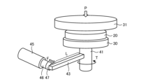
- Fig. 1 is a diagram illustrating an example of the configuration of a measuring device 10 according to the first embodiment.
- the measuring device 10 is a device that measures the chucking force of an electrostatic chuck 20 that is an object to be measured.
- the electrostatic chuck 20 corresponds to the substrate chucking section of the present disclosure.
- the electrostatic chuck 20 is one that has been removed from a substrate processing apparatus that is actually in operation in order to measure a change in chucking force over time, or one that has not yet been mounted on the substrate processing apparatus for pre-shipment inspection or the like.
- the electrostatic chuck 20 has a mounting surface 21 on which a substrate W, such as a semiconductor wafer, is placed.
- the electrostatic chuck 20 is configured to be able to adsorb the substrate W placed on the mounting surface 21.
- the electrostatic chuck 20 includes a ceramic member 22 and an electrostatic electrode 23 disposed within the ceramic member 22.
- the electrostatic chuck 20 electrostatically adsorbs the substrate W by applying a voltage to the electrostatic electrode 23.
- the measuring device 10 is configured to be able to measure the force required to shift the substrate W on the electrostatic chuck 20 in an adsorption state in which the substrate W is adsorbed by the electrostatic chuck 20.
- the measuring device 10 is configured to calculate the adsorption force of the electrostatic chuck 20 based on the measured force.
- the measuring device 10 has a stage 30 that holds the electrostatic chuck 20.
- the electrostatic chuck 20 is fixed to the stage 30 by adhesive or a mechanical fixing mechanism such as a bolt.
- the measuring device 10 is configured to be able to press the substrate W against the electrostatic chuck 20 held on the stage 30.
- the measuring device 10 includes a substrate holding plate 31 and a fixing plate 32.
- the substrate holding plate 31 and the fixing plate 32 are formed to be wider than the stage 30.
- the substrate W is fixed to the underside of the substrate holding plate 31 by adhesive or a mechanical fixing mechanism such as a bolt.
- the substrate holding plate 31 is disposed above the stage 30.
- the fixed plate 32 is disposed above the substrate holding plate 31.
- the substrate holding plate 31 and the fixed plate 32 are supported by a number of poles 33.
- the fixed plate 32 is fixed at its upper end to a number of poles 33.
- the substrate holding plate 31 has a through hole through which the pole 33 passes.
- a small gap is provided between the substrate holding plate 31 and the pole 33 that passes through the through hole, and the substrate holding plate 31 is configured to be movable up and down along the pole 33.
- a ring 34 is provided on the underside of the substrate holding plate 31 for the pole 33. The ring 34 restricts the substrate holding plate 31 from moving downward.
- the lower end of each pole 33 is fixed to a base 40 provided below the stage 30.
- a plate 36 is provided on the underside of the fixed plate 32 via a pressure sensor 35.
- a plurality of contact members 37 are provided on the underside of the plate 36.
- a semicircular protrusion 37a is formed on the underside of the contact member 37. The entire contact member 37 or the protrusion 37a portion is formed from an elastic material.
- the stage 30 has a support portion 41 connected to the center of its underside.
- the support portion 41 is formed in a cylindrical shape, passes through an opening 40a formed in the base 40, and is connected to a lifting mechanism 42 provided below the base 40.
- the lifting mechanism 42 rotatably supports the support portion 41 and is configured to be able to raise and lower the support portion 41.
- the stage 30 is raised and lowered by the lifting mechanism 42 raising and lowering the support portion 41.
- the stage 30, the substrate holding plate 31, the fixed plate 32, the pole 33, the plate 36, the contact member 37, the support portion 41, and the lifting mechanism 42 correspond to the pressing mechanism of the present disclosure.
- the pressure sensor 35 corresponds to the pressure measuring unit of the present disclosure.
- the arm 43 is provided on the side of the support part 41 in a direction perpendicular to the central axis of the support part 41.
- the arm 43 is fixed to the support part 41.
- the support part 41 rotates as the arm 43 moves.
- the measuring device 10 is provided with an actuator 45 such as a gas cylinder.
- the actuator 45 is capable of extending and retracting a rod 46.
- the actuator 45 is provided at a position corresponding to the end of the arm 43.
- the tip of the rod 46 of the actuator 45 is connected to the arm 43.
- the distance from the rotation axis of the support part 41 to the connection position between the arm 43 and the rod 46 is L.
- a torque is applied to the support part 41 via the arm 43.
- the support part 41 rotates around the central axis.
- the stage 30, the support part 41, the arm 43, and the actuator 45 correspond to the rotation mechanism of the present disclosure.
- a pressure sensor 47 is provided at the connection between the rod 46 and the arm 43.
- the pressure sensor 47 measures the torque that rotates the electrostatic chuck 20 by measuring the pressure with which the rod 46 presses the arm 43.
- the pressure sensor 47 corresponds to the measurement unit of the present disclosure.
- the measuring device 10 has a DC power supply 48.
- the DC power supply 48 is connected to the electrostatic electrode 23 of the electrostatic chuck 20 via wiring 49.
- the DC power supply 48 applies a voltage to the electrostatic electrode 23 via the wiring 49.
- a voltage is applied from the DC power supply 48 to the electrostatic electrode 23, an electrostatic force is generated in the electrostatic chuck 20, and the substrate W is attracted to the electrostatic chuck 20.
- the measuring device 10 has a control unit 50.
- a user interface 51 and a memory unit 52 are connected to the control unit 50.
- the user interface 51 is composed of an operation section such as a keyboard through which the user inputs commands to operate the measuring device 10, and a display section such as a display that visualizes and displays the operating status and measurement results of the measuring device 10.
- the storage unit 52 stores data such as control programs (software) for executing various processes executed by the measuring device 10 and processing parameters.
- the control programs and data may be stored in a computer-readable computer recording medium (e.g., a hard disk, an optical disk such as a DVD, a flexible disk, a semiconductor memory, etc.).
- the control programs and data may also be stored in another device and read and used online, for example, via a dedicated line.
- the control unit 50 is, for example, a computer having a processor, a memory, and an input/output interface.
- the control unit 50 controls each part of the measurement device 10 via the input/output interface.
- the control unit 50 controls the DC power supply 48 to control the voltage applied from the DC power supply 48 to the electrostatic electrode 23.
- the control unit 50 also controls the lifting mechanism 42 to control the lifting and lowering of the stage 30.
- the control unit 50 also controls the actuator 45 to control the rotation of the stage 30.
- the control unit 50 reads the control program and data stored in the storage unit 52 into memory based on instructions from the user interface 51, and executes the processing of the read control program with a processor. Based on the control program, the control unit 50 controls each part of the measuring device 10 via the input/output interface, thereby executing various processes including the measurement process described below.
- the electrostatic chuck 20, which is to be the object of the measurement of the adhesive force is fixed to the stage 30.
- the substrate W used for measuring the adhesive force is fixed to the underside of the substrate holding plate 31.
- the substrate W may be a substrate in a state in which it will actually be processed in the substrate processing apparatus in which the electrostatic chuck 20 is mounted.
- Substrates such as semiconductor wafers undergo various process steps, and therefore undergo deformations in shape such as bending.
- the measuring device 10 presses the substrate W against the electrostatic chuck 20.
- the control unit 50 controls the lifting mechanism 42, which lifts the support 41 and the stage 30.
- the stage 30 rises, the upper surface of the electrostatic chuck 20 held on the stage 30 comes into contact with the substrate W held on the substrate holding plate 31.
- the substrate holding plate 31 rises with the electrostatic chuck 20 and the substrate W in contact, and the upper surface of the substrate holding plate 31 comes into contact with each contact member 37 of the fixed plate 32.
- the lifting mechanism 42 further applies a force to lift the support 41, a downward stress is applied to the substrate holding plate 31 from the fixed plate 32 via each contact member 37.
- the substrate holding plate 31 is configured to be movable up and down along the pole 33, and a downward stress is applied to the substrate holding plate 31 via a plurality of contact members 37, so that the substrate holding plate 31 can press the substrate W substantially uniformly against the mounting surface 21 of the electrostatic chuck 20.
- the pressing force related to the configuration of the first embodiment is, for example, a maximum of standard atmospheric pressure + 0.1 MPa.
- the measuring device 10 applies a force to rotate the electrostatic chuck 20 in each of the adsorption state in which the electrostatic chuck 20 adsorbs the substrate W and the detached state in which the electrostatic chuck 20 does not adsorb the substrate W, and measures the torque at which the electrostatic chuck 20 starts to rotate.
- the control unit 50 controls the DC power supply 48 to turn on and off the voltage applied to the electrostatic electrode 23 to switch the electrostatic chuck 20 between the adsorption state and the detached state.
- the voltage value of the voltage applied in the adsorption state may be input from the user interface 51 or may be stored in advance in the memory unit 52.
- the control unit 50 controls the actuator 45 in each of the adsorption state and the detached state, and extends the rod 46 of the actuator 45 to push the arm 43 to apply a force to rotate the support unit 41, thereby rotating the stage 30 and the electrostatic chuck 20.
- the control unit 50 uses the pressure sensor 47 to measure the pressure at which the electrostatic chuck 20 starts to rotate in the adsorption state and the detached state.
- the control unit 50 calculates the torque at which the electrostatic chuck 20 starts to rotate in the attracted and unattracted states from the measured pressures in the attracted and unattracted states and the distance L from the rotation axis of the support unit 41 to the connection position of the arm 43 and the rod 46.
- control unit 50 multiplies the measured pressures in the attracted and unattracted states by the distance L from the rotation axis of the support unit 41 to the connection position of the arm 43 and the rod 46 to calculate the torque at which the electrostatic chuck 20 starts to rotate in the attracted and unattracted states.
- the measuring device 10 also measures the pressure pressing the substrate W against the electrostatic chuck 20.
- the control unit 50 measures the pressure using the pressure sensor 35.
- the measuring device 10 calculates the adsorption force of the electrostatic chuck 20 from the torque in the adsorbed state, the torque in the unadsorbed state, and the pressure pressing the substrate W against the electrostatic chuck 20.
- T the torque at which the electrostatic chuck 20 starts to rotate in the attracted state
- T' the torque at which the electrostatic chuck 20 starts to rotate in the non-attracted state
- P the pressure pressing the substrate W against the electrostatic chuck 20
- ⁇ the attracting force of the electrostatic chuck 20
- ⁇ the dynamic friction coefficient between the electrostatic chuck 20 and the substrate W
- the control unit 50 calculates the adsorption force N of the electrostatic chuck 20 using equation (2) from the torque T in the adsorbed state, the torque T' in the unadsorbed state, and the pressure P pressing the substrate W against the electrostatic chuck 20.
- the control unit 50 also calculates the dynamic friction coefficient ⁇ using equation (3) from the diameter D of the substrate W, the torque T in the adsorbed state, and the pressure P pressing the substrate W against the electrostatic chuck 20.
- the diameter D of the substrate W may be input from the user interface 51, or may be stored in advance in the memory unit 52.
- the control unit 50 outputs the calculated adhesion force N and dynamic friction coefficient ⁇ of the electrostatic chuck 20. For example, the control unit 50 displays the adhesion force N and dynamic friction coefficient ⁇ of the electrostatic chuck 20 on the display unit of the user interface 51.
- the measuring device 10 applies a rotational force to the electrostatic chuck 20 in contact with the substrate W, measures the force (torque) required to displace the substrate W on the electrostatic chuck 20, and calculates the adhesion force N of the electrostatic chuck 20 based on the measured force.
- the measuring device 10 can measure the force required to displace the substrate W with good reproducibility, and can quantitatively measure the adhesion force of the electrostatic chuck 20 with good reproducibility.
- the electrostatic chuck 20 By being able to measure the chucking force of the electrostatic chuck 20 quantitatively and reproducibly in this way, it is possible to measure the change in the chucking force due to the applied voltage to the electrostatic electrode 23. This makes it possible to determine the applied voltage suitable for chucking the substrate W.
- the electrostatic chuck 20 is periodically removed from the substrate processing apparatus, and the chucking force of the electrostatic chuck 20 is measured by the measuring device 10. By determining the change in the chucking force over time, it is possible to determine the timing for replacing the electrostatic chuck 20.
- the change in the chucking force of the electrostatic chuck 20 over time in one of the substrate processing apparatuses can be determined, and the timing for replacing the electrostatic chuck 20 in the other substrate processing apparatuses can also be determined.
- the chucking force of the electrostatic chuck 20 decreases over time from the time when the voltage is turned off. Therefore, by measuring the change in the chucking force of the electrostatic chuck 20 over time from the time when the voltage applied to the electrostatic electrode 23 is turned off, it is possible to determine the appropriate timing for lifting the substrate W from the electrostatic chuck 20.
- FIG. 3 is a flowchart showing an example of the flow of a measurement process according to the first embodiment.
- the measuring device 10 presses the substrate W against the electrostatic chuck 20 (step S10).
- the control unit 50 controls the lifting mechanism 42 to raise the support part 41 and the stage 30 using the lifting mechanism 42, and the electrostatic chuck 20 is pressed against the mounting surface 21 by the substrate W held by the substrate holding plate 31.
- the measuring device 10 measures the pressure P that presses the substrate W against the electrostatic chuck 20 (step S11).
- the control unit 50 measures the pressure P using the pressure sensor 35.
- the measuring device 10 measures the torque T' at which the electrostatic chuck 20 starts to rotate in an unattached state (step S12).
- the control unit 50 controls the DC power supply 48 to turn off the voltage applied to the electrostatic electrode 23, switching the electrostatic chuck 20 to an unattached state.
- the control unit 50 extends the rod 46 of the actuator 45, and the rod 46 pushes the arm 43 to apply a force that rotates the support part 41, thereby rotating the stage 30 and the electrostatic chuck 20.
- the control unit 50 uses the pressure sensor 47 to measure the pressure at which the stage 30 and the electrostatic chuck 20 start to rotate.
- the control unit 50 multiplies the measured pressure by the distance L, respectively, to calculate the torque T' at which the electrostatic chuck 20 starts to rotate in an unattached state.
- the measuring device 10 measures the torque T at which the electrostatic chuck 20 starts to rotate in the adsorption state (step S13).
- the control unit 50 controls the DC power supply 48 to apply a voltage to the electrostatic electrode 23 to switch the electrostatic chuck 20 to the adsorption state.
- the control unit 50 extends the rod 46 of the actuator 45 and pushes the arm 43 with the rod 46, thereby applying a force to rotate the support part 41 and rotate the stage 30 and the electrostatic chuck 20.
- the control unit 50 uses the pressure sensor 47 to measure the pressure at which the stage 30 and the electrostatic chuck 20 start to rotate.
- the control unit 50 multiplies the measured pressure by the distance L to calculate the torque T at which the electrostatic chuck 20 starts to rotate in the adsorption state.
- step S11 may be executed in parallel with step S12 or step S13. Also, the processing order of steps S12 and S13 may be reversed.
- the measuring device 10 calculates the adsorption force N of the electrostatic chuck 20 (step S14).
- the control unit 50 calculates the adsorption force N of the electrostatic chuck 20 from the torque T in the adsorption state, the torque T' in the non-adsorption state, and the pressure P pressing the substrate W against the electrostatic chuck 20 using the above-mentioned formula (2).
- the measuring device 10 calculates the dynamic friction coefficient ⁇ of the electrostatic chuck 20 (step S15).
- the control unit 50 calculates the dynamic friction coefficient ⁇ from the diameter D of the substrate W, the torque T in the adsorption state, and the pressure P pressing the substrate W against the electrostatic chuck 20 using the above-mentioned formula (3).
- the measuring device 10 outputs the adsorption force N and the dynamic friction coefficient ⁇ of the electrostatic chuck 20 (step S16) and ends the process.
- the control unit 50 displays the adsorption force N and the dynamic friction coefficient ⁇ of the electrostatic chuck 20 on the display unit of the user interface 51.
- FIG. 4 is a diagram showing an example of the configuration of a substrate processing apparatus 60 according to the second embodiment.
- the substrate processing apparatus 60 is an apparatus that performs various substrate processing such as etching, film formation, and ashing on a substrate W.
- the substrate processing apparatus 60 may be a vacuum processing apparatus having an airtight chamber and performing substrate processing on the substrate W in the reduced pressure chamber.
- the substrate processing apparatus 60 may also be a coating apparatus such as a spin coater that performs substrate processing such as film formation on the substrate W in an atmospheric pressure environment.
- the substrate processing apparatus 60 has a configuration similar to that of the measuring apparatus 10 shown in FIG. 1, so that the same parts are denoted by the same reference numerals and the description is omitted, and the different parts will be mainly described.
- the substrate processing apparatus 60 has a stage 30 and a DC power supply 48.
- the stage 30 is provided with an electrostatic chuck 20.
- the DC power supply 48 is connected to the electrostatic electrode 23 of the electrostatic chuck 20 via wiring 49.
- the DC power supply 48 applies a voltage to the electrostatic electrode 23 via wiring 49.
- the electrostatic chuck 20 attracts the substrate W by applying a voltage from the DC power supply 48 to the electrostatic electrode 23.
- a substrate W is transported and placed on the mounting surface 21 of the electrostatic chuck 20 by a transport mechanism 61 such as a transport arm.
- the transport mechanism 61 is provided with a pick 62 at its tip, which holds and transports the substrate W.
- the transport mechanism 61 is also configured to be able to press the substrate W placed on the electrostatic chuck 20 with the tip of the pick 62.
- the transport mechanism 61 is provided with a pressure sensor 63 on the pick 62 that can measure the pressure when the substrate W is pressed.
- the substrate processing apparatus 60 has a control unit 70.
- a user interface 71 and a memory unit 72 are connected to the control unit 70.
- the user interface 71 is composed of an operation section such as a keyboard through which the user inputs commands to operate the substrate processing apparatus 60, and a display section such as a display that visualizes and displays the operating status and measurement results of the substrate processing apparatus 60.
- the memory unit 72 stores data such as control programs (software) for executing various processes performed by the substrate processing apparatus 60 and process parameters.
- the memory unit 72 stores applied voltage data indicating the voltage value to be applied when in an adsorption state.
- the voltage value of the applied voltage data is set so as to obtain a predetermined adsorption force capable of stably holding the substrate W.
- the control programs and data may be stored in a computer-readable computer recording medium.
- the control programs and data may also be stored in another device and read out and used online, for example, via a dedicated line.
- the control unit 70 is, for example, a computer having a processor, a memory, and an input/output interface.
- the control unit 70 controls each part of the substrate processing apparatus 60 via the input/output interface.
- the control unit 70 controls the DC power supply 48 to control the voltage applied from the DC power supply 48 to the electrostatic electrode 23.
- the control unit 70 reads the control program and data stored in the storage unit 72 into memory based on instructions from the user interface 71, and executes the processing of the read control program with a processor. Based on the control program, the control unit 70 controls each part of the substrate processing apparatus 60 via the input/output interface, thereby executing various processes including the calibration process described below.
- the substrate W is transported by the transport mechanism 61, and the substrate W is placed on the mounting surface 21.
- the substrate processing apparatus 60 adsorbs the substrate W placed on the mounting surface 21 with the electrostatic chuck 20.
- the control unit 50 reads the applied voltage data from the memory unit 72, controls the DC power supply 48, and applies a voltage of the voltage value of the applied voltage data to the electrostatic electrode 23, thereby adsorbing the substrate W with the electrostatic chuck 20.
- the electrostatic chuck 20 may experience changes in adhesion force even when the same voltage value is applied to the electrostatic electrode 23.
- the substrate processing apparatus 60 measures the adsorption force of the electrostatic electrode 23.
- the control unit 50 controls the DC power supply 48 to apply a voltage of the voltage value of the applied voltage data to the electrostatic electrode 23, thereby adsorbing the substrate W by the electrostatic chuck 20.
- the measuring apparatus 10 measures the force required to shift the substrate W adsorbed to the electrostatic chuck 20.
- the pick 62 of the transport mechanism 61 is pressed against the side surface of the substrate W. Note that if an edge ring is provided around the substrate W, this is performed with the edge ring removed.
- FIG. 5 is a schematic diagram showing an example of a state in which the side of the substrate W is pressed by the transport mechanism 61.
- the control unit 70 uses the pressure sensor 63 to measure the pressure at which the substrate W starts to move in the adsorbed state.
- the pressure at which the substrate W starts to move corresponds to the force required for the substrate W to start moving.
- the force required for the substrate W to start moving in the attracted state is denoted as F
- the attracting force of the electrostatic chuck 20 is denoted as N
- the dynamic friction coefficient between the electrostatic chuck 20 and the substrate W is denoted as ⁇ .
- F ⁇ N (4)
- the substrate processing apparatus 60 calculates the adsorption force N of the electrostatic chuck 20.
- the control unit 70 calculates the adsorption force N of the electrostatic chuck 20 from the force F required for the substrate W to start moving in the adsorption state and the kinetic friction coefficient ⁇ of the electrostatic chuck 20 using equation (5).
- the kinetic friction coefficient ⁇ of the electrostatic chuck 20 may be input from the user interface 51 or may be stored in advance in the memory unit 52.
- the kinetic friction coefficient ⁇ of the electrostatic chuck 20 can be obtained by the measuring apparatus 10 of the first embodiment described above.
- the kinetic friction coefficient ⁇ may be changed over time.
- kinetic friction coefficient data that defines the kinetic friction coefficient ⁇ of the electrostatic chuck 20 for each number of substrate processing operations or the number of substrates W processed is stored in the memory unit 72.
- the control unit 70 counts the number of substrate processing operations or the number of substrates processed after the electrostatic chuck 20 is replaced with a new one.
- the control unit 70 may obtain the kinetic friction coefficient ⁇ corresponding to the number of processes or the number of processed wafers at that time from the kinetic friction coefficient data, and use the obtained kinetic friction coefficient ⁇ to calculate the adsorptive force N of the electrostatic chuck 20.
- the substrate processing apparatus 60 calibrates the adsorption force N of the electrostatic chuck 20 by correcting the applied voltage data so as to obtain a predetermined adsorption force capable of stably holding the substrate W. For example, when the calculated adsorption force N is lower than the predetermined adsorption force, the control unit 70 corrects the applied voltage data so as to increase the adsorption force. For example, the control unit 70 corrects the applied voltage data so as to increase the voltage value.
- correction data that defines a correction value for the voltage value for each difference between the adsorption force and the predetermined adsorption force may be stored in the storage unit 72 in advance. The control unit 70 may obtain a correction value corresponding to the difference between the predetermined adsorption force and the calculated adsorption force N from the correction data, and correct the voltage value of the applied voltage data by the obtained correction value.
- FIG. 6 is a flowchart showing an example of the flow of a calibration process according to the second embodiment.
- the substrate W is transported by the transport mechanism 61 and placed on the placement surface 21.
- the substrate processing apparatus 60 adsorbs the substrate W placed on the mounting surface 21 with the electrostatic chuck 20 (step S20).
- the control unit 50 controls the DC power supply 48 to apply a voltage of the voltage value of the applied voltage data to the electrostatic electrode 23, thereby adsorbing the substrate W with the electrostatic chuck 20.
- the measuring device 10 measures the force required to shift the substrate W attracted to the electrostatic chuck 20 (step S21). For example, the pick 62 of the transport mechanism 61 presses against the side of the substrate W.
- the control unit 70 uses the pressure sensor 63 to measure the force F required for the substrate W to start moving in the attracted state.
- the measuring device 10 calculates the adsorption force N of the electrostatic chuck 20 (step S22).
- the control unit 70 calculates the adsorption force N of the electrostatic chuck 20 using the force F required for the substrate W to start moving in the adsorption state and the dynamic friction coefficient ⁇ of the electrostatic chuck 20, using formula (5).
- the substrate processing apparatus 60 corrects the applied voltage data so as to obtain a predetermined adsorptive force capable of stably holding the substrate W, calibrates the adsorptive force N of the electrostatic chuck 20 (step S23), and ends the process. For example, if the calculated adsorptive force N is lower than the predetermined adsorptive force, the control unit 70 corrects the applied voltage data so as to increase the adsorptive force.
- the method of measuring the adhesion force disclosed herein can measure the adhesion force in either an atmospheric pressure environment or a reduced pressure environment.
- the measuring device 10 and the substrate processing device 60 may be configured to measure the adhesion force in a reduced pressure environment, such as in a reduced pressure chamber.
- the substrate adsorption portion is an electrostatic chuck 20, and the adsorption force for electrostatically adsorbing the substrate W is measured.
- the substrate adsorption portion may have any configuration as long as it is capable of adsorbing the substrate.
- the method for adsorbing the substrate W may be other methods, such as adsorption by suction.
- the stage 30 to which the electrostatic chuck 20 is fixed is raised, and the electrostatic chuck 20 is pressed against the substrate W fixed to the underside of the substrate holding plate 31.
- the disclosed technology is not limited to this.
- the substrate holding plate 31 may be lowered to press the substrate W against the electrostatic chuck 20.
- the stage 30 to which the electrostatic chuck 20 is fixed is rotated to measure the force required to shift the substrate W on the electrostatic chuck 20.
- the disclosed technology is not limited to this.
- a configuration may be used in which the substrate holding plate 31 to which the substrate W is fixed is rotated to measure the force required to shift the substrate W on the electrostatic chuck 20.
Landscapes
- Physics & Mathematics (AREA)
- General Physics & Mathematics (AREA)
- Chemical & Material Sciences (AREA)
- Analytical Chemistry (AREA)
- Engineering & Computer Science (AREA)
- Automation & Control Theory (AREA)
- Mechanical Engineering (AREA)
- Health & Medical Sciences (AREA)
- Life Sciences & Earth Sciences (AREA)
- Biochemistry (AREA)
- General Health & Medical Sciences (AREA)
- Immunology (AREA)
- Pathology (AREA)
- Container, Conveyance, Adherence, Positioning, Of Wafer (AREA)
Priority Applications (3)
| Application Number | Priority Date | Filing Date | Title |
|---|---|---|---|
| JP2025519406A JPWO2024232306A1 (https=) | 2023-05-11 | 2024-04-30 | |
| KR1020257036954A KR20260002839A (ko) | 2023-05-11 | 2024-04-30 | 측정 장치, 측정 방법 및 교정 방법 |
| US19/378,369 US20260056114A1 (en) | 2023-05-11 | 2025-11-04 | Measurement apparatus, measurement method, and calibration method |
Applications Claiming Priority (2)
| Application Number | Priority Date | Filing Date | Title |
|---|---|---|---|
| JP2023-078642 | 2023-05-11 | ||
| JP2023078642 | 2023-05-11 |
Related Child Applications (1)
| Application Number | Title | Priority Date | Filing Date |
|---|---|---|---|
| US19/378,369 Continuation US20260056114A1 (en) | 2023-05-11 | 2025-11-04 | Measurement apparatus, measurement method, and calibration method |
Publications (1)
| Publication Number | Publication Date |
|---|---|
| WO2024232306A1 true WO2024232306A1 (ja) | 2024-11-14 |
Family
ID=93430189
Family Applications (1)
| Application Number | Title | Priority Date | Filing Date |
|---|---|---|---|
| PCT/JP2024/016631 Ceased WO2024232306A1 (ja) | 2023-05-11 | 2024-04-30 | 測定装置、測定方法及び校正方法 |
Country Status (5)
| Country | Link |
|---|---|
| US (1) | US20260056114A1 (https=) |
| JP (1) | JPWO2024232306A1 (https=) |
| KR (1) | KR20260002839A (https=) |
| TW (1) | TW202501702A (https=) |
| WO (1) | WO2024232306A1 (https=) |
Cited By (1)
| Publication number | Priority date | Publication date | Assignee | Title |
|---|---|---|---|---|
| CN120293385A (zh) * | 2025-06-16 | 2025-07-11 | 无锡卓瓷科技有限公司 | 一种陶瓷吸盘吸力测试装置 |
Citations (8)
| Publication number | Priority date | Publication date | Assignee | Title |
|---|---|---|---|---|
| JPS57205040U (https=) * | 1981-06-25 | 1982-12-27 | ||
| JPS5957446A (ja) * | 1982-09-28 | 1984-04-03 | Kokusai Electric Co Ltd | 静電吸着式基板保持装置 |
| JPH02249935A (ja) * | 1989-03-23 | 1990-10-05 | Toto Ltd | 静電チャックの吸着力評価方法及び評価装置 |
| JPH06119637A (ja) * | 1992-10-02 | 1994-04-28 | Sumitomo Metal Mining Co Ltd | 磁気ディスクの製造方法 |
| JPH06170670A (ja) * | 1992-12-08 | 1994-06-21 | Fuji Electric Co Ltd | 静電チャック装置およびその運転方法 |
| JP2003110012A (ja) * | 2001-09-28 | 2003-04-11 | Nissin Electric Co Ltd | 基板保持方法およびその装置 |
| CN103698068A (zh) * | 2013-12-06 | 2014-04-02 | 清华大学 | 一种静电卡盘基本性能检测装置及其检测方法 |
| JP2019536290A (ja) * | 2016-11-23 | 2019-12-12 | アプライド マテリアルズ インコーポレイテッドApplied Materials,Incorporated | プロセスチャンバキャリアのための静電チャッキング力測定ツール |
Family Cites Families (1)
| Publication number | Priority date | Publication date | Assignee | Title |
|---|---|---|---|---|
| JP5670235B2 (ja) | 2011-03-24 | 2015-02-18 | コバレントマテリアル株式会社 | 静電チャック |
-
2024
- 2024-04-30 JP JP2025519406A patent/JPWO2024232306A1/ja active Pending
- 2024-04-30 WO PCT/JP2024/016631 patent/WO2024232306A1/ja not_active Ceased
- 2024-04-30 KR KR1020257036954A patent/KR20260002839A/ko active Pending
- 2024-05-06 TW TW113116669A patent/TW202501702A/zh unknown
-
2025
- 2025-11-04 US US19/378,369 patent/US20260056114A1/en active Pending
Patent Citations (8)
| Publication number | Priority date | Publication date | Assignee | Title |
|---|---|---|---|---|
| JPS57205040U (https=) * | 1981-06-25 | 1982-12-27 | ||
| JPS5957446A (ja) * | 1982-09-28 | 1984-04-03 | Kokusai Electric Co Ltd | 静電吸着式基板保持装置 |
| JPH02249935A (ja) * | 1989-03-23 | 1990-10-05 | Toto Ltd | 静電チャックの吸着力評価方法及び評価装置 |
| JPH06119637A (ja) * | 1992-10-02 | 1994-04-28 | Sumitomo Metal Mining Co Ltd | 磁気ディスクの製造方法 |
| JPH06170670A (ja) * | 1992-12-08 | 1994-06-21 | Fuji Electric Co Ltd | 静電チャック装置およびその運転方法 |
| JP2003110012A (ja) * | 2001-09-28 | 2003-04-11 | Nissin Electric Co Ltd | 基板保持方法およびその装置 |
| CN103698068A (zh) * | 2013-12-06 | 2014-04-02 | 清华大学 | 一种静电卡盘基本性能检测装置及其检测方法 |
| JP2019536290A (ja) * | 2016-11-23 | 2019-12-12 | アプライド マテリアルズ インコーポレイテッドApplied Materials,Incorporated | プロセスチャンバキャリアのための静電チャッキング力測定ツール |
Cited By (1)
| Publication number | Priority date | Publication date | Assignee | Title |
|---|---|---|---|---|
| CN120293385A (zh) * | 2025-06-16 | 2025-07-11 | 无锡卓瓷科技有限公司 | 一种陶瓷吸盘吸力测试装置 |
Also Published As
| Publication number | Publication date |
|---|---|
| JPWO2024232306A1 (https=) | 2024-11-14 |
| KR20260002839A (ko) | 2026-01-06 |
| US20260056114A1 (en) | 2026-02-26 |
| TW202501702A (zh) | 2025-01-01 |
Similar Documents
| Publication | Publication Date | Title |
|---|---|---|
| US20260056114A1 (en) | Measurement apparatus, measurement method, and calibration method | |
| US8383000B2 (en) | Substrate processing apparatus, method for measuring distance between electrodes, and storage medium storing program | |
| JP7482749B2 (ja) | リフトピンのコンタクト位置調整方法、リフトピンのコンタクト位置検知方法、および基板載置機構 | |
| CN101174548A (zh) | 测量卡盘附着力的设备和方法 | |
| EP2564272A2 (en) | Ball-spacer method for planar object leveling | |
| JP2008300414A (ja) | 薄膜形成装置および薄膜形成方法 | |
| JP4037726B2 (ja) | 真空プローブ装置及び真空プローブ方法 | |
| TW202135186A (zh) | 用於監測、位置測定及定位頂銷系統的方法 | |
| JP2023114739A (ja) | 成膜装置、成膜方法、及び電子デバイスの製造方法 | |
| CN101689529A (zh) | 处理基板的技术 | |
| JP5222177B2 (ja) | 基板処理装置および基板保持機構 | |
| JP2003285289A (ja) | ハンドリング装置及び搬送装置並びにハンドリング方法 | |
| JP4852477B2 (ja) | 薄膜形成装置および薄膜形成方法 | |
| JP2011249657A (ja) | 試料吸着保持装置および試料吸着判定方法 | |
| JP2004228488A (ja) | 基板搬送方法 | |
| JP2012023104A (ja) | 基板載置装置 | |
| JP2014203975A (ja) | 薄膜形成装置 | |
| JP3799336B2 (ja) | 基板処理装置におけるリングチャックの取り扱い方法 | |
| JP3771766B2 (ja) | 静電チャック評価装置及び静電チャック評価方法 | |
| JP6326261B2 (ja) | 薄膜形成装置 | |
| JP4852476B2 (ja) | 薄膜形成装置および薄膜形成方法 | |
| JP4490524B2 (ja) | 静電吸着ステージ及び基板処理装置 | |
| JP2014126762A (ja) | 基板貼り合わせ装置及び基板貼り合わせ方法 | |
| JP3223291B2 (ja) | 静電チャック試料台 | |
| JP2010192516A (ja) | 薄膜形成装置 |
Legal Events
| Date | Code | Title | Description |
|---|---|---|---|
| 121 | Ep: the epo has been informed by wipo that ep was designated in this application |
Ref document number: 24803419 Country of ref document: EP Kind code of ref document: A1 |
|
| ENP | Entry into the national phase |
Ref document number: 2025519406 Country of ref document: JP Kind code of ref document: A |
|
| WWE | Wipo information: entry into national phase |
Ref document number: 2025519406 Country of ref document: JP |
|
| NENP | Non-entry into the national phase |
Ref country code: DE |