WO2024232288A1 - 眼科画像処理プログラムおよび眼科画像処理装置 - Google Patents
眼科画像処理プログラムおよび眼科画像処理装置 Download PDFInfo
- Publication number
- WO2024232288A1 WO2024232288A1 PCT/JP2024/016228 JP2024016228W WO2024232288A1 WO 2024232288 A1 WO2024232288 A1 WO 2024232288A1 JP 2024016228 W JP2024016228 W JP 2024016228W WO 2024232288 A1 WO2024232288 A1 WO 2024232288A1
- Authority
- WO
- WIPO (PCT)
- Prior art keywords
- image
- image processing
- oct
- ophthalmologic
- data
- Prior art date
- Legal status (The legal status is an assumption and is not a legal conclusion. Google has not performed a legal analysis and makes no representation as to the accuracy of the status listed.)
- Ceased
Links
Images


Classifications
-
- A—HUMAN NECESSITIES
- A61—MEDICAL OR VETERINARY SCIENCE; HYGIENE
- A61B—DIAGNOSIS; SURGERY; IDENTIFICATION
- A61B3/00—Apparatus for testing the eyes; Instruments for examining the eyes
- A61B3/10—Objective types, i.e. instruments for examining the eyes independent of the patients' perceptions or reactions
Definitions
- the present disclosure relates to an ophthalmic image processing program and an ophthalmic image processing device that process OCT data of tissue of a test eye.
- optical coherence tomography is a device that captures tomographic images of tissues in the subject's eye.
- OCT optical coherence tomography
- One type of OCT is the SS-OCT (Swept Source-OCT) method, which uses a wavelength-swept light source as the light source, changing the emitted wavelength at high speed over time (see Patent Document 1).
- SS-OCT Single Source-OCT
- SD-OCT Spectrum Domain-OCT
- the wavelength is changed very quickly to emit light, making control complex.
- the phase of the wavelength sweep at each sampling timing of the interference signal vibrates irregularly (fluctuations), and resampling of the interference signal into wavenumber space fails, which can cause noise in the tomographic image.
- This noise is more likely to be a problem in areas farther away from zero delay.
- This noise is difficult to suppress using calculations to generate OCT data from spectral interference signals (for example, k-space resampling methods such as the mapping arm method and the k-clock method).
- additive averaging of multiple images is widely used as a method to reduce noise, but phase noise in the wavelength sweep originating from the light source is difficult to remove using additive averaging.
- the present invention was made in consideration of the above circumstances, and has as its technical objective the provision of an ophthalmic image processing program and an ophthalmic image processing device that can obtain tomographic images of good image quality in each area.
- the ophthalmic image processing program is an ophthalmic image processing program executed by an ophthalmic image processing device that processes ophthalmic images, which are images of tissues of a test eye.
- the ophthalmic image processing program is executed by a control unit of the ophthalmic image processing device, causing the ophthalmic image processing device to execute a base image acquisition step of acquiring, as a base image, a tomographic image captured by an SS-OCT device having a wavelength swept light source as an OCT light source, and a target image acquisition step of acquiring a target image by inputting the base image into a mathematical model trained by a machine learning algorithm so as to output an image in which the phase noise of the wavelength sweep originating from the OCT light source in the input image is at least reduced.
- the ophthalmological image processing device executes the ophthalmological image processing program according to the first aspect described above.
- cross-sectional images of good image quality are obtained in each region.
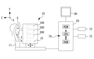
- FIG. 1 is a diagram showing a schematic configuration of an OCT system according to an embodiment.
- FIG. 2 is a diagram showing an OCT optical system according to an embodiment.
- 10 is a flow chart illustrating an example of a computational process for generating OCT data from a spectral interference signal.
- 13 is a flowchart showing a process for reducing phase noise in wavelength sweeping.
- FIG. 1 is a diagram for explaining a mathematical model.
- FIG. 11 is a diagram for explaining the reduction process.
- FIG. 13 is a diagram for explaining a modified example.
- FIG. 11 is a diagram for explaining a second modified example.
- An ophthalmic image processing program according to the embodiment is executed by an ophthalmic image processing device that processes ophthalmic images, which are images of the tissues of a subject's eye.
- the control unit also called the "processor” of the ophthalmic image processing device
- at least the base image acquisition step and the target image acquisition step are executed.
- a tomographic image captured by an SS-OCT device having a wavelength swept light source as an OCT light source is acquired as the base image.
- the base image is input to a mathematical model trained by a machine learning algorithm so as to output an image in which at least the phase noise of the wavelength sweep originating from the OCT light source in the input image is reduced, thereby acquiring the target image.
- Phase noise is noise that occurs when the phase of the wavelength sweep at each sampling timing of the interference signal oscillates irregularly (fluctuations), and resampling of the interference signal into wavenumber space fails.
- Phase noise is difficult to suppress using the mapping arm method and the k-clock method, and is also difficult to suppress using conventional image processing such as averaging processing using multiple images.
- the phase noise component can be appropriately suppressed by using a mathematical model trained by a machine learning algorithm so as to output an image in which at least the phase noise of the wavelength sweep originating from the OCT light source in the input image is reduced.
- a mathematical model trained by a machine learning algorithm so as to output an image in which at least the phase noise of the wavelength sweep originating from the OCT light source in the input image is reduced.
- the mathematical model refers to, for example, a data structure for predicting the relationship between input data and output data.
- the mathematical model is constructed by training using a training data set.
- the training data set may be a set of input training data and output training data.
- the correlation data e.g., weights
- the program and data for realizing the constructed mathematical model are incorporated into the fundus image processing device.
- Machine learning algorithms include neural networks, random forests, boosting, and support vector machines (SVMs).
- a multi-layered neural network is used as the machine learning algorithm.
- the neural network includes an input layer for inputting data, an output layer for generating data of the analysis result to be predicted, and one or more hidden layers between the input layer and the output layer.
- a plurality of nodes are arranged in each layer.
- a convolutional neural network (CNN), which is a type of multi-layered neural network, is used.
- CNN convolutional neural network
- GAN generative adversarial network
- the mathematical model used in the target image acquisition step of this embodiment may be trained using data of a tomographic image captured with a specific part of the subject's eye positioned in a first region of the imaging range in the depth direction of the tomographic image as output training data, and also using data of a noise-added image in which a phase noise component corresponding to a second region farther away from the zero delay than the first region is added to the tomographic image captured with a specific part of the subject's eye positioned in the first region as input training data.
- the above mathematical model is trained with a training data set of input training images having phase noise components and output training images in which the phase noise components have been reduced, but is not necessarily limited to this.
- the mathematical model of this embodiment may be trained based on a technique called Noise2Noise to remove noise.
- the mathematical model that outputs an image in which the phase noise of the wavelength sweep from the OCT light source has been reduced may be trained with an image having a phase noise component, without using an image in which the phase noise components have been reduced as an output training image. That is, in this embodiment, the mathematical model trained to reduce the phase noise components is trained based on an image having a phase noise component.
- the mathematical model may be trained using data on tomographic images taken by multiple OCT devices and noise-added images corresponding to the tomographic images. Since the phase noise characteristics of the wavelength sweep originating from the OCT light source differ for each device (each light source), by training using data on tomographic images taken by multiple OCT devices and noise-added images corresponding to the tomographic images, noise can be reduced effectively without necessarily training the mathematical model based on images from the device actually used.
- the mathematical model may also be trained using a number of noise-added images, to which phase noise components corresponding to different depth positions have been added, as input training data. This makes it easier to obtain a target image in which the phase noise of the wavelength sweep originating from the light source is effectively suppressed, regardless of the depth position of a specific portion in the input image.
- Example An OCT system (optical coherence tomography system) shown in FIGS. 1 and 2 will be described below as an embodiment.
- the OCT system includes at least an optical unit 10 and a control unit 50, which corresponds to the computer of the embodiment.
- the optical unit 10 and the control unit 50 are integrated as an OCT device.
- the OCT system (OCT device) according to the embodiment has a basic configuration of swept-wavelength OCT (SS-OCT).
- the optical unit 10 includes a light-guiding optical system 150. Furthermore, in this embodiment, the optical unit 10 includes a fundus observation optical system 200 and an anterior segment observation optical system 300.
- the optical unit 10 can be moved three-dimensionally by the XYZ moving unit 15.
- the XYZ moving unit 15 is driven and controlled by the arithmetic controller 70.
- the XYZ moving unit 15 moves the optical unit 10 three-dimensionally, thereby adjusting the three-dimensional position of the optical unit 10 with respect to the subject's eye E. This aligns the three-dimensional position of the optical unit 10 with respect to the subject's eye E.
- the subject's face is supported by the face support unit 17.
- the support position of the face by the face support unit 17 can be moved in the vertical direction.
- the control unit 50 is an ophthalmic image processing device in this embodiment, and includes at least an arithmetic controller (processor) 70 that controls the entire OCT system.
- the arithmetic controller 70 is configured, for example, with a CPU and memory.
- the arithmetic controller 70 also serves as an image processor in the OCT system.
- the OCT system may also be provided with a storage unit (memory) 72, an input interface (operation unit) 75, a monitor 80, etc. Each unit is connected to the calculation controller 70.
- Various programs, initial values, etc. for controlling the operation of the OCT device may be stored in memory 72.
- memory 72 may store various information related to imaging, in addition to OCT images generated from OCT data.
- Monitor 80 may display the OCT data (OCT images).
- the OCT optical system 100 guides measurement light to the test eye E by a light guide optical system 150.
- the OCT optical system 100 guides reference light to a reference optical system 110.
- the OCT optical system 100 causes a detector (light receiving element) 120 to receive spectral interference signal light obtained by interference between the measurement light reflected by the test eye E and the reference light.
- the OCT optical system 100 uses the SS-OCT method.
- the OCT optical system 100 has a wavelength swept light source as the OCT light source 102.
- the OCT optical system 100 has a point detector as the detector 120.
- the wavelength of the swept light source is swept over time.
- the OCT light source 102 may be a VCSEL-type swept light source.
- the VCSEL-type swept light source includes a VCSEL that is responsible for laser oscillation and a MEMS that realizes high-speed scanning.
- the detector 120 is a balanced detector that performs balanced detection using multiple (e.g., two) detectors.
- the arithmetic and control unit 70 samples the interference signal between the reference light and the return light of the measurement light in response to changes in the emission wavelength from the wavelength swept light source, and obtains OCT data of the test eye based on the interference signal at each wavelength obtained by sampling.
- the coupler (splitter) 104 is used as a first optical splitter and splits the light emitted from the light source 102 into a measurement optical path and a reference optical path.
- the coupler 104 guides the light from the light source 102 to an optical fiber 152 on the measurement optical path side and also guides the light to a reference optical system 110 on the reference optical path side.
- the light-guiding optical system 150 is provided to guide the measurement light to the eye E.
- the light-guiding optical system 150 may be provided, for example, with an optical fiber 152, a collimator lens 153, a focusing lens 155, an optical scanner 156, and an objective lens system 158 (the objective optical system in this embodiment) in that order.
- the measurement light is emitted from the exit end of the optical fiber 152 and is converted into a parallel beam by the collimator lens 153.
- the measurement light is directed to the optical scanner 156 via the focusing lens 155.
- the focusing lens 155 can be displaced along the optical axis by a driving unit (not shown) and is used to adjust the light-gathering state.
- the light that has passed through the optical scanner 156 is irradiated to the eye E via the objective lens system 158.
- a pivot point P is formed at a position conjugate with the optical scanner 156 with respect to the objective lens system 158 (provided in the device body).
- the optical scanner 156 may scan the measurement light in the XY directions (transverse directions) on the tissue of the subject's eye E.
- the optical scanner 156 is, for example, two galvanometer mirrors, whose reflection angle is arbitrarily adjusted by a drive mechanism.
- the light beam emitted from the light source 102 has its reflection (traveling) direction changed and is scanned in an arbitrary direction on the tissue of the subject's eye E.
- a reflection mirror galvanometer mirror, polygon mirror, resonant scanner
- AOM acousto-optical element
- the scattered light (reflected light) from the eye E due to the measurement light travels back along the path taken when the light was projected, enters the optical fiber 152, and reaches the coupler 104.
- the coupler 104 guides the light from the optical fiber 152 to an optical path toward the detector 120.
- the reference optical system 110 generates a reference light.
- the reference light is combined with the measurement light reflected from the subject's eye E.
- the reference light passing through the reference optical system 110 is combined with light from the measurement optical path by a coupler 148 and interferes with each other.
- the reference optical system 110 may be a Michelson type or a Mach-Zehnder type.
- the reference optical system 110 shown in FIG. 2 is formed by a transmission optical system, as an example.
- the reference optical system 110 guides the light from the coupler 104 to the detector 120 by transmitting it without returning it.
- the reference optical system 110 may be formed by a reflection optical system, for example, and guide the light from the coupler 104 to the detector 120 by reflecting it with the reflection optical system.
- an optical path length difference adjustment unit 145 and a polarization adjustment unit 147 are arranged on the optical path from the coupler 104 to the detector 120.
- the optical path length difference adjustment unit 145 is used to adjust the optical path length difference between the measurement light and the reference light.
- it is necessary to adjust the optical path length difference between the measurement light and the reference light in advance, at least according to the depth position of the imaging target (part of the test eye E).
- a mirror 145a having two orthogonal surfaces is provided on the reference light path.
- the optical path length of the reference light path can be increased or decreased by moving this mirror 145a in the direction of the arrow by the actuator 145b.
- the configuration for adjusting the optical path length difference between the measurement light and the reference light is not limited to this.
- the collimator lens 153 and the coupler may be moved together to adjust the optical path length of the measurement light, and as a result, the optical path length difference between the measurement light and the reference light may be adjusted.
- the polarization adjustment unit 147 adjusts the polarization of the reference light.
- the polarization adjustment unit may be disposed on the measurement light path.
- the calculation controller 70 processes (performs Fourier analysis) the spectral interference signal detected by the detector 120 to obtain OCT data (OCT image) of the subject's eye (S101).
- the detector 120 detects the spectral interference signal as a beat signal whose intensity changes over time based on the wavelength sweep.
- the calculation controller 70 performs mapping processing (S104) on the spectral interference signal for each A-scan after DC-subtraction (processing to remove direct current components) (S102) and zero padding (processing) (S103).
- the arithmetic controller 70 performs a dispersion correction process (S105) on the resampled spectral interference signal I(k).
- the result is Fourier transformed (FFT) (S106), and mirror images are removed (S108) to obtain A-scan OCT data.
- A-scan OCT data obtained in this way is acquired in multiple pieces in the transverse direction, and B-scan OCT data is constructed by arranging these consecutively (S109).
- a process for reducing phase noise of the wavelength sweep originating from the light source is performed on the generated B-scan OCT data.
- the phase noise ⁇ of the wavelength sweep originating from the light source occurs due to the phase of the wavelength sweep vibrating irregularly, and resampling of the interference signal into the wave number space fails.
- OCT averaging processing of multiple images is widely used as a method for reducing noise, but the phase noise ⁇ of the wavelength sweep originating from the light source is difficult to remove by averaging processing.
- zs is the sample depth
- ls is the reflectance from that depth
- t is time
- ⁇ zs is an arbitrary phase.
- phase noise increases as the sample depth increases, that is, in areas farther away from zero delay. Therefore, the noise in the image due to phase noise becomes more noticeable the wider the imaging range in the depth direction. In other words, it appears as fuzziness in the image and a decrease in resolution in the depth direction.
- a mathematical model trained by a machine learning algorithm is used to obtain OCT data with reduced phase noise. That is, in this reduction process, as shown in FIG. 4, OCT data is input to the mathematical model as a base image (S201). As a result, OCT data with higher image quality than the input OCT data is obtained as a target image (S202).
- the mathematical model refers to, for example, a data structure for predicting the relationship between input data and output data.
- the mathematical model is constructed by training using a training data set.
- the training data set is a set of input training data and output training data.
- the correlation data e.g., weights
- a program and data for realizing the constructed mathematical model are incorporated into the control unit 50 and the arithmetic controller 70.
- Machine learning algorithms include neural networks, random forests, boosting, and support vector machines (SVMs).
- a multi-layered neural network is used as the machine learning algorithm.
- the neural network includes an input layer for inputting data, an output layer for generating data of the analysis result to be predicted, and one or more hidden layers between the input layer and the output layer.
- a plurality of nodes are arranged in each layer.
- a convolutional neural network (CNN), which is a type of multi-layered neural network, is used.
- CNN convolutional neural network
- GAN generative adversarial network
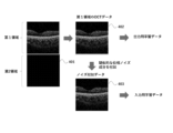
- the mathematical model is trained in advance so that an image in which at least the phase noise of the wavelength sweep originating from the light source in the input image is reduced is output.
- high-quality OCT data 402 with less phase noise is used as output training data
- noise-added data 403 obtained by adding phase noise to the high-quality OCT data is used as input training data.
- the high-quality OCT data 402 used as output training data may be generated by extracting a first region from OCT data 401 captured with a predetermined part of the subject's eye positioned in a first region near zero delay in the imaging range in the depth direction.
- the noise-added data 403 may be generated by adding pseudo phase noise corresponding to the depth position of a second region farther away from zero delay than the first region to the extracted OCT data 401.
- an OCT image can be generated in which the phase noise of the wavelength sweep originating from the light source is reduced.
- the pseudo phase noise added to the high-quality OCT data can be calculated, for example, as follows.
- it can be derived based on the interference signal of a gold mirror.
- the interference signal of the gold mirror can be written as follows.
- phase noise function is set to A ⁇ e B ⁇ t .
- OCT analysis signal expressed as exponential data after Hilbert transformation
- a and B appearing in the phase noise function are functions of the frequency of the gold mirror signal (depth of the gold mirror) to be acquired, and need to be adjusted appropriately.
- the depth position at which a specific part is depicted is not constant for each imaging. Depending on alignment errors, individual differences in the subject's eye, and the like, the depth position at which a specific part is depicted may differ for each imaging. Therefore, in this embodiment, the pseudo phase noise added to each noise-added data of the training data set may correspond to different depth positions.
- a mathematical model trained with such a training data set makes it easier to effectively suppress the phase noise of the wavelength sweep originating from the light source, regardless of the depth position at which the specific part is depicted.
- the imaging range in the depth direction corresponding to the OCT data of the base image may be a wide range including the first region and the second region. Therefore, the reduction process of this embodiment may process a partial image, which is a partial depth region of the captured OCT data in which a specific part is depicted, as the base image.
- the phase noise of the wavelength sweep is reduced in the manner described above. Therefore, even if a certain tissue must be positioned away from the zero delay in the OCT data, a tomographic image with good image quality can be obtained.
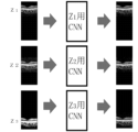
- the depth position at which the predetermined part is depicted may differ for each imaging.
- a mathematical model may be prepared for each depth position at which the predetermined part is depicted.
- three mathematical models corresponding to depth positions Z1 , Z2 , and Z3 are prepared.
- a mathematical model corresponding to a certain depth position is trained using the above-mentioned high-quality OCT data 402 as an output training image, and is trained using noise-added data 403 in which phase noise at the corresponding depth position is added to the high-quality OCT data 402 as an input training image.
- OCT data with reduced phase noise may be obtained by inputting a base image into one of the multiple (three in FIG. 7) mathematical models corresponding to the depth position at which the predetermined part is depicted in the base image.
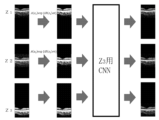
- OCT data with reduced phase noise can be obtained by a single mathematical model regardless of the depth position at which the predetermined part is depicted in the base image. That is, the base image may be subjected to pre-processing to make the degree of phase noise constant for each image, and then the base image may be input to a single mathematical model to obtain OCT data with reduced phase noise.
- the mathematical model is trained using OCT data in which a phase noise component corresponding to a predetermined depth position is added to high-quality OCT data as an input training image. For example, in the example of FIG.
- the mathematical model is trained using the above-mentioned high-quality OCT data 402 as an output training image, and is trained using OCT data in which a phase noise component corresponding to the deepest depth position Z 3 among depth positions Z 1 , Z 2 , and Z 3 is added to the high-quality OCT data 402 as an input training image.
- a phase noise component is added according to the depth position by pre-processing.
- phase noise component is added so that the depth position at which the predetermined part is depicted is approximately the same as that at Z3 .
- the phase noise component to be added can be appropriately calculated using the above-mentioned phase noise function expressed as A ⁇ e B ⁇ t . Note that, as shown in FIG. 8, A and B are both functions that depend on the depth Z.
- processor refers to one or more hardware processors configured to execute program code (i.e., one or more instructions of a program) contained in a program.
- program code i.e., one or more instructions of a program
- a "processor” is a hardware device capable of executing one or more programmed processes.
- a "processor” may be a general-purpose or special-purpose processor, such as, but not limited to, a CPU, a microprocessor, a GPU, and a data flow processor (DFP).
- DFP data flow processor
- the term "memory” refers to one or more hardware memories that are non-transient tangible recording media and are configured to store computer program code and/or data accessible to a processor.
- the "memory” may be realized using memory technologies such as SRAM, SDRAM, non-volatile/flash type memory, or other types of memory.
- Computer program code constituting a program may be stored in the memory and executed by the processor to cause the ophthalmic image processing device to realize various functions.
Landscapes
- Life Sciences & Earth Sciences (AREA)
- Health & Medical Sciences (AREA)
- Medical Informatics (AREA)
- Biophysics (AREA)
- Ophthalmology & Optometry (AREA)
- Engineering & Computer Science (AREA)
- Biomedical Technology (AREA)
- Heart & Thoracic Surgery (AREA)
- Physics & Mathematics (AREA)
- Molecular Biology (AREA)
- Surgery (AREA)
- Animal Behavior & Ethology (AREA)
- General Health & Medical Sciences (AREA)
- Public Health (AREA)
- Veterinary Medicine (AREA)
- Eye Examination Apparatus (AREA)
Priority Applications (1)
| Application Number | Priority Date | Filing Date | Title |
|---|---|---|---|
| JP2025519395A JPWO2024232288A1 (https=) | 2023-05-08 | 2024-04-25 |
Applications Claiming Priority (2)
| Application Number | Priority Date | Filing Date | Title |
|---|---|---|---|
| JP2023-076964 | 2023-05-08 | ||
| JP2023076964 | 2023-05-08 |
Publications (1)
| Publication Number | Publication Date |
|---|---|
| WO2024232288A1 true WO2024232288A1 (ja) | 2024-11-14 |
Family
ID=93430103
Family Applications (1)
| Application Number | Title | Priority Date | Filing Date |
|---|---|---|---|
| PCT/JP2024/016228 Ceased WO2024232288A1 (ja) | 2023-05-08 | 2024-04-25 | 眼科画像処理プログラムおよび眼科画像処理装置 |
Country Status (2)
| Country | Link |
|---|---|
| JP (1) | JPWO2024232288A1 (https=) |
| WO (1) | WO2024232288A1 (https=) |
Citations (4)
| Publication number | Priority date | Publication date | Assignee | Title |
|---|---|---|---|---|
| WO2018021561A1 (ja) * | 2016-07-29 | 2018-02-01 | 株式会社ニデック | 眼科装置、およびiol度数決定プログラム |
| WO2020183799A1 (ja) * | 2019-03-11 | 2020-09-17 | キヤノン株式会社 | 医用画像処理装置、医用画像処理方法及びプログラム |
| WO2022234828A1 (ja) * | 2021-05-06 | 2022-11-10 | 国立大学法人筑波大学 | 情報処理装置およびプログラム |
| JP2022185838A (ja) * | 2021-06-03 | 2022-12-15 | 株式会社ニデック | Oct装置および撮影制御プログラム |
-
2024
- 2024-04-25 JP JP2025519395A patent/JPWO2024232288A1/ja active Pending
- 2024-04-25 WO PCT/JP2024/016228 patent/WO2024232288A1/ja not_active Ceased
Patent Citations (4)
| Publication number | Priority date | Publication date | Assignee | Title |
|---|---|---|---|---|
| WO2018021561A1 (ja) * | 2016-07-29 | 2018-02-01 | 株式会社ニデック | 眼科装置、およびiol度数決定プログラム |
| WO2020183799A1 (ja) * | 2019-03-11 | 2020-09-17 | キヤノン株式会社 | 医用画像処理装置、医用画像処理方法及びプログラム |
| WO2022234828A1 (ja) * | 2021-05-06 | 2022-11-10 | 国立大学法人筑波大学 | 情報処理装置およびプログラム |
| JP2022185838A (ja) * | 2021-06-03 | 2022-12-15 | 株式会社ニデック | Oct装置および撮影制御プログラム |
Also Published As
| Publication number | Publication date |
|---|---|
| JPWO2024232288A1 (https=) | 2024-11-14 |
Similar Documents
| Publication | Publication Date | Title |
|---|---|---|
| US10718601B2 (en) | Optical coherence tomography device | |
| JP5794664B2 (ja) | 断層画像生成装置及び断層画像生成方法 | |
| JP5279524B2 (ja) | 光断層撮像装置、光断層撮像方法 | |
| JP5685013B2 (ja) | 光断層撮像装置及びその制御方法、プログラム | |
| US8678588B2 (en) | Optical coherence tomographic imaging apparatus | |
| US8317326B2 (en) | Optical tomographic imaging method and apparatus | |
| JP6987522B2 (ja) | 画像生成装置、画像生成方法、及びプログラム | |
| US10582850B2 (en) | OCT motion contrast acquisition method and optical coherence tomography device | |
| US20090091766A1 (en) | Optical coherence tomographic apparatus | |
| JP6491540B2 (ja) | 光干渉断層計およびその制御方法 | |
| JP5639523B2 (ja) | 光干渉断層撮影装置、光干渉断層撮影装置の制御方法、プログラムおよび眼科システム | |
| JP2015226579A (ja) | 光干渉断層撮影装置及び光干渉断層撮影装置の制御方法 | |
| US10478059B2 (en) | Imaging apparatus | |
| JP2017196307A (ja) | 眼科撮像装置 | |
| JP2019063242A (ja) | Oct装置、および、眼科用画像処理プログラム | |
| US8873065B2 (en) | Tomographic imaging apparatus and tomographic imaging method | |
| JP2019080804A (ja) | Oct装置 | |
| JP7159408B2 (ja) | 両眼光コヒーレンストモグラフィ撮像システム | |
| JP7339447B2 (ja) | ライン走査マイクロスコピー用の装置および方法 | |
| US9795291B2 (en) | Optical coherence tomography device and optical coherence tomography control program | |
| WO2024232288A1 (ja) | 眼科画像処理プログラムおよび眼科画像処理装置 | |
| JP6166509B2 (ja) | 撮像装置及び撮像方法 | |
| JP2018033506A (ja) | 断層撮像装置、画像生成装置、断層撮像方法、画像生成方法、及びプログラム | |
| JP2024097725A (ja) | Oct装置 | |
| WO2022186115A1 (ja) | Oct装置および眼科画像処理プログラム |
Legal Events
| Date | Code | Title | Description |
|---|---|---|---|
| 121 | Ep: the epo has been informed by wipo that ep was designated in this application |
Ref document number: 24803401 Country of ref document: EP Kind code of ref document: A1 |
|
| ENP | Entry into the national phase |
Ref document number: 2025519395 Country of ref document: JP Kind code of ref document: A |
|
| WWE | Wipo information: entry into national phase |
Ref document number: 2025519395 Country of ref document: JP |
|
| NENP | Non-entry into the national phase |
Ref country code: DE |