WO2024232005A1 - 無線通信システム - Google Patents
無線通信システム Download PDFInfo
- Publication number
- WO2024232005A1 WO2024232005A1 PCT/JP2023/017400 JP2023017400W WO2024232005A1 WO 2024232005 A1 WO2024232005 A1 WO 2024232005A1 JP 2023017400 W JP2023017400 W JP 2023017400W WO 2024232005 A1 WO2024232005 A1 WO 2024232005A1
- Authority
- WO
- WIPO (PCT)
- Prior art keywords
- information
- wireless communication
- terminal
- surrounding environment
- communication
- Prior art date
- Legal status (The legal status is an assumption and is not a legal conclusion. Google has not performed a legal analysis and makes no representation as to the accuracy of the status listed.)
- Ceased
Links
Images




Classifications
-
- H—ELECTRICITY
- H04—ELECTRIC COMMUNICATION TECHNIQUE
- H04W—WIRELESS COMMUNICATION NETWORKS
- H04W16/00—Network planning, e.g. coverage or traffic planning tools; Network deployment, e.g. resource partitioning or cells structures
- H04W16/22—Traffic simulation tools or models
-
- H—ELECTRICITY
- H04—ELECTRIC COMMUNICATION TECHNIQUE
- H04W—WIRELESS COMMUNICATION NETWORKS
- H04W24/00—Supervisory, monitoring or testing arrangements
Definitions
- This disclosure relates to wireless communication systems.
- wireless communication is used for a variety of purposes. However, depending on the service, wireless communication may not be able to meet certain communication quality requirements.
- Non-Patent Document 1 discloses a technology for predicting the quality of wireless communication using distance information between the terminal and a base station.
- Non-Patent Document 2 discloses a technology that determines whether radio waves are blocked by fixing the wireless communication terminal.
- This disclosure has been made in consideration of the above circumstances, and the purpose of this disclosure is to provide technology that can predict the communication quality of wireless communication with high accuracy and reduce the costs associated with learning and using a prediction model.
- a wireless communication system includes a base station device and at least two devices among a plurality of devices including one or more mobile wireless communication devices, and at least one of the two devices includes a first processing unit that processes device information including at least one of the position, orientation, speed, operation, control status, and usage status of the device itself or the other device, a second processing unit that processes surrounding environment information related to the surrounding environment of the device, a third processing unit that processes communication information related to the wireless communication of the device, a generation unit that performs machine learning on the relationship between the device information and the surrounding environment information and the communication information, and generates a prediction model that predicts communication information related to wireless communication based on the device information and the surrounding environment information, and a prediction unit that predicts communication information related to wireless communication based on the input device information and surrounding environment information using the prediction model.
- the present disclosure provides technology that can predict the communication quality of wireless communication with high accuracy and reduce the costs associated with learning and using predictive models.
- FIG. 1 is a diagram showing the configuration of a wireless communication system.
- FIG. 2 is a diagram illustrating a method for generating a prediction model.
- FIG. 3A is a diagram showing an example of surrounding environment information.
- FIG. 3B is a diagram showing an example of surrounding environment information.
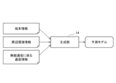
- FIG. 4A is a diagram illustrating an example of generation of a prediction model.
- FIG. 4B is a diagram illustrating an example of generation of a prediction model.
- FIG. 5 is a diagram showing a method for predicting target information.
- FIG. 6 is a top view showing the indoor experimental environment and terminal movements.
- FIG. 7A is a diagram showing an example of a predicted throughput.
- FIG. 7B is a diagram showing an example of a predicted throughput.
- FIG. 7A is a diagram showing an example of a predicted throughput.
- FIG. 7C is a diagram showing an example of a predicted throughput.
- FIG. 7D is a diagram showing an example of a predicted throughput.
- FIG. 8 is a diagram showing the R2 scores of the predicted results for each throughput.
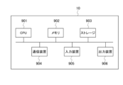
- FIG. 9 is a diagram showing the hardware configuration of a base station and a mobile radio communication terminal.
- the radio wave propagation environment between the communication party changes depending on the state of the wireless communication terminal (e.g., position, posture, movement) and the state of static or dynamic objects existing around the wireless communication terminal, which may degrade the communication quality of wireless communication and significantly affect the services realized by wireless communication.
- the higher the frequency used the more directional the radio waves tend to be, and the more susceptible the communication quality of wireless communication is to be affected.
- modeling the relationship between communication quality and environmental information using machine learning is considered to be a useful method. If a predictive model is constructed using machine learning, it is possible to use input signals obtained from the state of the wireless communication terminal and environmental information to output predicted values for wireless communication quality and control information for the wireless communication system.
- the present disclosure therefore predicts the communication quality of wireless communication using a machine learning model, using physical space information relating to various physical spaces, including terminal information and surrounding environment information, as input information.
- the present disclosure inputs terminal information, including at least one of the position, orientation, speed, operation, control status, and usage status of the terminal performing wireless communication, and surrounding environment information relating to the terminal's surrounding environment, into a prediction model, and makes a prediction. This makes it possible to predict the communication quality of wireless communication with a high degree of accuracy.
- terminal information including at least one of the terminal's position, orientation, speed, operation, control status, and usage status
- the number of machine learning parameters to be optimized is reduced, and the costs associated with learning and using the predictive model can be reduced.
- FIG. 1 is a diagram showing the configuration of a wireless communication system according to this embodiment.
- the wireless communication system 1 includes a base station 10 connected to a specific communication network, and a first mobile wireless communication terminal 20A and a second mobile wireless communication terminal 20B that perform wireless communication with the base station 10 and/or with each other.
- the number of mobile wireless communication terminals may be one or more.
- the base station 10 includes a first processing unit 11, a second processing unit 12, a third processing unit 13, a generating unit 14, a predicting unit 15, a first communication unit 16a, and a second communication unit 16b.
- the number of communication units may be one or more.
- the base station 10 may be a wireless LAN router or the like.
- the first processing unit 11 has a function of processing (generating, acquiring) terminal information (device information) related to the terminal to be predicted.
- the terminal to be predicted is, for example, the first mobile wireless communication terminal 20A, which is a partner terminal with which wireless communication is performed.
- the terminal information is, for example, the position, orientation, speed, and operation (e.g., rotation of the terminal, change of antenna angle), control status (e.g., the presence or absence of control commands for circuits, control command information, total amount of execution commands for application programs), and usage status (e.g., CPU usage, data communication volume) of the first mobile wireless communication terminal 20A, which is the other terminal with which wireless communication is performed.
- the first processing unit 11 processes the terminal information including at least one of these.
- the second processing unit 12 has the function of processing (generating and acquiring) surrounding environment information related to the surrounding environment of the base station 10 and the other terminal.
- the surrounding environment information is, for example, image information captured by the base station 10's built-in camera or a camera installed in the surrounding environment, sensor information sensed by a sensor installed in the surrounding environment, information extracted from the image information and sensor information, information about other terminals present in the vicinity of the base station 10 (for example, position information, orientation information, speed information, terminal information, and control information of the second mobile wireless communication terminal 20B that is not the other terminal with which wireless communication is performed), and information other than other terminals present in the vicinity of the base station 10 (for example, position information, orientation information, and speed information of passersby).
- the surrounding environment information is information about objects (for example, terminals, passersby, vehicles, and buildings) present in the vicinity of the base station 10 or the other terminal.
- the surrounding environment information may be information generated based on such information.
- the second processing unit 12 may generate the surrounding environment information based on object distribution data obtained from sensor information (object distribution data including the base station 10, its manager, the manager's belongings, the first mobile wireless communication terminal 20A, its owner/occupant, the owner's/occupant's belongings/occupied items, etc.).
- the third processing unit 13 has a function of processing (acquiring, generating) communication information related to wireless communication between the base station 10 and the other terminal. For example, the third processing unit 13 acquires communication information related to wireless communication between the base station 10 and the first mobile wireless communication terminal 20A.
- the communication information related to wireless communication is information related to wireless communication signals and wireless communication data obtained from the first communication unit 16a and the second communication unit 16b.
- the information includes received signal power, signal-to-noise power ratio, signal-to-interference plus noise power ratio, RSSI (Received Signal Strength Indication), RSRQ (Received Signal Reference Quality), packet error rate, number of arriving bits, bit error rate, number of arriving bits per unit time, MCS (Modular Code Index), number of retransmissions, packet arrival delay time, error correction technology settings, user contract information of the mobile wireless communication terminal, differential information of these values, indices calculated from these values using a predetermined formula, frequency conditions such as the frequency of the wireless communication system and the bandwidth of the resources used, and setting items of the wireless communication system that affect these indices.
- the generation unit 14 has a function of inputting the terminal information, the surrounding environment information, and the communication information related to wireless communication as learning data, and using an arbitrary machine learning algorithm to perform machine learning on the relationship between the terminal information, the surrounding environment information, and the communication information related to wireless communication, and generating a prediction model that predicts the communication information related to wireless communication as target information based on the terminal information and the surrounding environment information.
- the generation unit 14 can also perform learning by adding wireless communication system information.
- the generation unit 14 generates a prediction model that predicts communication information related to wireless communication as target information based on the terminal information, surrounding environment information, and wireless communication system information.
- the prediction unit 15 has a function of predicting communication information related to wireless communication as target information based on the input terminal information and surrounding environment information using a prediction model. When wireless communication system information is available, the prediction unit 15 predicts communication information related to wireless communication as target information based on the input terminal information, surrounding environment information, and wireless communication system information.
- Target information is, for example, communication information related to wireless communication, and parameters for controlling wireless communication.
- the contents of the target information can be selected arbitrarily.
- Parameters are, for example, information on the movement of the base station 10 and the other terminal, control information in the OSI reference model from the physical layer to the application layer (e.g., mode, communication speed, communication destination, communication path, communication method), and control information on structures, metamaterials, and dielectrics that affect the radio wave propagation environment (e.g., control information related to position, movement, and settings).
- the first communication unit 16a has the function of performing wireless communication with the first mobile wireless communication terminal 20A.
- the second communication unit 16b has a function of performing wireless communication with the second mobile wireless communication terminal 20B.
- the first mobile radio communication terminal 20A is, for example, a mobile phone terminal or a smartphone terminal, and includes a first processing unit 21A, a second processing unit 22A, a third processing unit 23A, a generating unit 24A, a predicting unit 25A, and a communication unit 26A.
- the first processing unit 21A like the first processing unit 11 of the base station 10, has a function of processing (obtaining, generating) terminal information related to the terminal to be predicted.
- the terminal to be predicted may be the base station 10, the second mobile wireless communication terminal 20B, or the first mobile wireless communication terminal 20A itself.
- the second processing unit 22A like the second processing unit 12 of the base station 10, has a function of processing (acquiring, generating) surrounding environment information related to the surrounding environment of the first mobile wireless communication terminal 20A.
- the second processing unit 22A may generate surrounding environment information based on object distribution data (object distribution data including the first mobile wireless communication terminal 20A, its owner/occupant, the possessions/occupancies of the owner/occupant, etc.) obtained from sensor information.
- object distribution data object distribution data including the first mobile wireless communication terminal 20A, its owner/occupant, the possessions/occupancies of the owner/occupant, etc.
- the third processing unit 23A like the third processing unit 13 of the base station 10, has the function of processing (acquiring, generating) communication information related to wireless communication between the first mobile wireless communication terminal 20A and the other terminal.
- the generation unit 24A has a function of inputting terminal information, surrounding environment information, and communication information related to wireless communication as learning data, and using any machine learning algorithm to perform machine learning on the relationship between the terminal information, surrounding environment information, and communication information related to wireless communication, and generating a prediction model that predicts communication information related to wireless communication as target information based on the terminal information and surrounding environment information.
- the generation unit 24A may also perform machine learning by adding wireless communication system information, and generate a prediction model that includes wireless communication system information in the input information.
- the prediction unit 25A like the prediction unit 15 of the base station 10, has a function of predicting communication information related to wireless communication as target information based on the input terminal information and surrounding environment information using a prediction model.
- the prediction unit 15 predicts communication information related to wireless communication as target information based on the input terminal information, surrounding environment information, and wireless communication system information.
- the communication unit 26A has the function of performing wireless communication with the first communication unit 16a of the base station 10, and performing wireless communication with the communication unit 26B of the second mobile wireless communication terminal 20B.
- the second mobile wireless communication terminal 20B is, for example, a mobile phone terminal or a smartphone terminal.
- the second mobile wireless communication terminal 20B includes a first processing unit 21B, a second processing unit 22B, a third processing unit 23B, a generating unit 24B, a predicting unit 25B, and a communication unit 26B.
- the second mobile wireless communication terminal 20B includes the same functions as the first mobile wireless communication terminal 20A. The description thereof will be omitted.
- the generation units 14, 24A, 24B that generate the predictive models may be provided in only one of the base station 10, the first mobile radio communication terminal 20A, and the second mobile radio communication terminal 20B, or may be provided in each terminal.
- the base station 10 which accommodates multiple mobile wireless communication terminals, to have it. This is because more wireless communication information can be collected and more training data can be used, which leads to improved accuracy of the prediction model. In this case, terminals other than the base station 10 use the prediction model generated by the base station 10.
- the prediction model may be optimized for each terminal using techniques such as transfer learning and fine tuning so that the prediction model is optimized for each terminal.
- wireless communication examples include wireless LAN (Local Area Network) defined by the standard IEEE 802.11, Bluetooth (registered trademark), cellular communication using LTE or 5G, LPWA (Low Power Wide Area) communication for IoT, ETC (Electronic Toll Collection System) used for vehicle communication, VICS (Vehicle Information and Communication System), and ARIB-STD-T109.
- wireless LAN Local Area Network
- Bluetooth registered trademark
- LPWA Low Power Wide Area
- LPWA Low Power Wide Area
- ETC Electronic Toll Collection System
- VICS Vehicle Information and Communication System
- ARIB-STD-T109 examples of wireless communication
- [Method of generating a predictive model] 2 is a diagram showing a method for generating a prediction model. A case in which a first mobile radio communication terminal 20A generates a prediction model will be described. It is assumed that the first mobile radio communication terminal 20A is performing radio communication with the base station 10.
- Step S101 The first processing section 21A acquires location information of the first mobile radio communication terminal 20A as terminal information.
- Step S102 The second processing unit 22A acquires point cloud data on the positions of objects in the surrounding environment from a LiDAR (Laser Imaging Detection and Ranging) installed in the surrounding environment of the first mobile wireless communication terminal 20A, converts the point cloud data into an image, and acquires the image as surrounding environment information. Examples of the image are shown in Figures 3A and 3B.
- the white parts represent the positions of the walls that form the experimental environment from an aerial perspective.
- Step S103 The third processing unit 23A acquires the throughput of the wireless communication carried out between the first mobile wireless communication terminal 20A and the base station 10 as communication information related to the wireless communication.
- Step S104 As shown in FIG. 4A , the generation unit 24A inputs terminal information (location information), surrounding environment information (image), and communication information related to wireless communication (throughput of wireless communication) as learning data, performs machine learning on the relationship between the terminal information and the surrounding environment information and the communication information related to wireless communication, and generates a prediction model that predicts the communication information related to wireless communication (throughput of wireless communication) as target information based on the terminal information and the surrounding environment information.
- terminal information location information
- surrounding environment information image
- communication information related to wireless communication throughput of wireless communication
- the generation unit 14 may perform learning by adding wireless communication system information and generate a prediction model that also uses the wireless communication system information as input information.
- [Method of predicting target information] 5 is a diagram showing a method for predicting target information. A case in which target information is predicted by a first mobile wireless communication terminal 20A will be described. It is assumed that the first mobile wireless communication terminal 20A is performing wireless communication with the base station 10.
- Step S201 The first processing unit 21A acquires the current location information of the first mobile radio communication terminal 20A as terminal information.
- Step S202 The second processing unit 22A acquires point cloud data regarding the current positions of objects in the surrounding environment from a LiDAR installed in the surrounding environment of the first mobile wireless communication terminal 20A, converts the point cloud data into an image, and acquires the image as surrounding environment information.
- Step S203 The prediction unit 15 uses the prediction model generated in step S104 to predict and output communication information related to wireless communication (throughput of wireless communication) as target information based on the terminal information (current location information) acquired in step S201 and the surrounding environment information (image related to point cloud data related to the current location) acquired in step S202.
- the prediction model is formed so as to output communication information related to wireless communication or some parameter as target information based on input information.
- the prediction model may be constructed so that the output value as target information is a highly accurate predicted value of some parameter, or it may output a strategy (improvement proposal) for changing the position of each communication unit to improve parameters related to wireless communication, or for the terminal components, surrounding environment, or from the application layer to the physical layer in the OSI reference model.
- the prediction model may be constructed by reinforcement learning so as to maximize the parameters related to wireless communication. For example, when predicting the received power at a future time, the received power at a future time is used as a parameter of the target information, and a prediction model is constructed so that the error between the predicted value of the output received power and the actual received power is reduced.
- a reward is set for maximizing the received power using reinforcement learning, and a prediction model is formed to output the X-coordinate velocity, Y-coordinate position velocity, and rotation command that will increase the reward.
- machine learning blocks constructed with the same coefficients and structure may be shared.
- a predictive model generated on one terminal and a predictive model generated on another terminal will have the same or similar structures if those terminals are in the same environment, so a predictive model can be generated using the same machine learning blocks, the other terminal's predictive model can be used as is, or part of the other terminal's predictive model can be modified to generate a predictive model. This allows predictive models to be constructed efficiently and reduces costs associated with the predictive models.
- Figure 6 is a top view showing the indoor experimental environment and the movement of the terminal. Two autonomous mobile robots equipped with a phantom simulating a human body and measuring devices for position information, etc. were driven.
- One of the robots was designated the target robot 300, and it was made to move around the experimental environment with a first mobile wireless communication terminal 20A capable of 5G communication strapped to its back, and UDP communication was carried out between the robot and base station 10, a 5G base station. The throughput of wireless communication between the first mobile wireless communication terminal 20A and base station 10 was measured.
- the other robot was a blocking robot 500, which was made to travel within the experimental environment as a robot that interferes with wireless communication between the first mobile wireless communication terminal 20A and the base station 10.
- the blocking robot 500 blocks the wireless communication path between the target robot 300 and the base station 10, thus affecting the wireless communication between them.
- the first mobile wireless communication terminal 20A acquires the position, orientation, forward speed, and rotation speed of the target robot 300 from the target robot 300 as terminal information.
- the first mobile wireless communication terminal 20A also acquires the position, orientation, forward speed, and rotation speed of the blocking robot 500 from the blocking robot 500 as surrounding environment information.
- the first mobile wireless communication terminal 20A uses the acquired terminal information and surrounding environment information as input information and predicts the throughput of wireless communication as target information.
- Figures 7A to 7D show the results of evaluation using four types of input information for the prediction.
- the horizontal axis is time, and the vertical axis is throughput.
- the solid lines in Figures 7A to 7D show the correct throughput to be predicted, as actually observed.
- the dashed line in Figure 7A shows the throughput prediction results when past throughput (two values in total: the current throughput value and the throughput value from 5 seconds ago) is used as input information.
- the dashed line in Figure 7B shows the throughput prediction result when the position information of the target robot 300 (two values in total: X coordinate value and Y coordinate value on a two-dimensional plane) is used as input information.
- the dashed line in Figure 7C shows the throughput prediction result when the position information, orientation information, and speed information of the target robot 300 (6 values in total: X coordinate value, Y coordinate value, sin( ⁇ /2) and cos( ⁇ /2) of the angle ⁇ from the X coordinate axis, speed in the direction of travel, and rotational speed) are used as input information.
- the dashed line in Figure 7D shows the throughput prediction result when the position information, orientation information, and speed information of the target robot 300 and the position information, orientation information, and speed information of the blocking robot 500 (a total of 12 values) are used as input information.
- the dashed line in Figure 7D shows the prediction result of this embodiment.
- each throughput prediction result was evaluated using the R2 score evaluation function shown in formula (1).
- C[t] is the throughput indicated by the solid line
- C ave [t] is the average throughput indicated by the solid line
- C'[t] is the throughput prediction result indicated by the dashed line.
- the R2 score for each throughput prediction result is shown in Figure 8.
- the R2 score when using past throughput is 0.61, and when predicted simply from the position information of the target robot (T robot) 300, it is 0.43, which is lower than the prediction when past throughput information is used.
- the orientation information and speed information of the target robot 300 are also used, it is 0.60, which is a prediction with a high level of accuracy equivalent to that when past throughput information is used.
- the prediction accuracy is 0.68, which confirms that a higher prediction accuracy is obtained. From this result, it can be said that by making predictions using both terminal information and surrounding environment information, the communication quality of wireless communication can be predicted with high accuracy.
- communication information related to wireless communication is predicted using a prediction model that predicts communication information related to wireless communication based on terminal information of the terminal and surrounding environment information related to the terminal's surrounding environment, so that the communication quality of wireless communication can be predicted with high accuracy.
- terminal information including at least one of the terminal's position, orientation, speed, operation, control status, and usage status is used, which reduces the number of machine learning parameters to be optimized and reduces the costs associated with learning and using the predictive model.
- the base station 10 of the present embodiment described above can be realized, for example, as shown in FIG. 9, by using a general-purpose computer system equipped with a CPU 901, memory 902, storage 903, communication device 904, input device 905, and output device 906.
- the memory 902 and storage 903 are storage devices.
- the CPU 901 executes a predetermined program loaded onto the memory 902, thereby realizing each function of the base station 10.
- the base station 10 may be implemented by one computer.
- the base station 10 may be implemented by multiple computers.
- the base station 10 may be a virtual machine implemented on a computer.
- the base station 10 may be realized using hardware such as a PLD (Programmable Logic Device) or an FPGA (Field Programmable Gate Array).
- the program for the base station 10 can be stored in a computer-readable recording medium such as a HDD, SSD, USB memory, CD, or DVD.
- the computer-readable recording medium is, for example, a non-transitory recording medium.
- the program for the base station 10 can also be distributed via a communication network such as the Internet or a telephone line.
- the first mobile wireless communication terminal 20A and the second mobile wireless communication terminal 20B also have the same hardware configuration as the base station 10.
- Base station 20A First mobile wireless communication terminal (mobile wireless communication device) 20B Second mobile wireless communication terminal (mobile wireless communication device) 11, 21A, 21B First processing unit 12, 22A, 22B Second processing unit 13, 23A, 23B Third processing unit 14, 24A, 24B Generation unit 15, 25A, 25B Prediction unit 16a First communication unit 16b Second communication unit 26A, 26B Communication unit 300 Target robot 500 Blocking robot 901 CPU 902 Memory 903 Storage 904 Communication device 905 Input device 906 Output device
Landscapes
- Engineering & Computer Science (AREA)
- Computer Networks & Wireless Communication (AREA)
- Signal Processing (AREA)
- Mobile Radio Communication Systems (AREA)
Abstract
基地局装置と1つ以上の移動無線通信装置とを含む複数の装置のうち少なくとも2つの装置を備えた無線通信システム1において、前記2つの装置のうち少なくとも1つの装置は、自装置又は相手装置の位置、向き、速度、動作、制御状況、利用状況のうち少なくとも1つを含む装置情報を処理する第1の処理部11、21A、21Bと、装置の周辺環境に関する周辺環境情報を処理する第2の処理部12、22A、22Bと、装置の無線通信に係る通信情報を処理する第3の処理部13、23A、23Bと、前記装置情報及び前記周辺環境情報と前記通信情報との関係性を機械学習し、装置情報及び周辺環境情報を基に無線通信に係る通信情報を予測する予測モデルを生成する生成部14、24A、24Bと、前記予測モデルを用いて、入力された装置情報及び周辺環境情報を基に無線通信に係る通信情報を予測する予測部15、25A、25Bと、を備える。
Description
本開示は、無線通信システムに関する。
現在、様々な用途で無線通信が使用されている。しかし、サービスによっては無線通信が一定の通信品質要求を満たすことができない場合がある。
例えば、無線通信端末が動くことにより、アンテナ指向性の向きや電波伝搬環境が変化するため、無線通信の通信品質が低下する。そこで、非特許文献1には、基地局との間の距離情報を用いて無線通信の通信品質を予測する技術が開示されている。
例えば、28GHz等の高周波数帯では、電波の直進性が高いため、無線通信端末が動くだけでなく、周辺のオブジェクトが動くことによっても、電波の遮蔽により無線通信の通信品質が低下する。そこで、非特許文献2には、無線通信端末を固定して電波の遮蔽の有無を判定する技術が開示されている。
Christopher J. Lowrance、外1名、"An active and incremental learning framework for the online prediction of link quality in robot networks"、Engineering Applications of Artificial Intelligence 77、2019年、p.197-p.211
Takayuki Nishio、外7名、"Proactive Received Power Prediction Using Machine Learning and Depth Images for mmWave Networks"、IEEE Journal on Selected Areas in Communications、vol.37、no.11、2019年11月、p.2413-p.2427
しかしながら、動きのある移動無線通信端末において、周辺のオブジェクトにより電波が遮蔽の影響を受けているかを正確に判定することは、困難であった。
本開示は、上記事情に鑑みてなされたものであり、本開示の目的は、無線通信の通信品質を高精度に予測可能であり、予測モデルの学習及び利用に係るコストを軽減可能な技術を提供することである。
本開示の一態様の無線通信システムは、基地局装置と1つ以上の移動無線通信装置とを含む複数の装置のうち少なくとも2つの装置を備えた無線通信システムにおいて、前記2つの装置のうち少なくとも1つの装置は、自装置又は相手装置の位置、向き、速度、動作、制御状況、利用状況のうち少なくとも1つを含む装置情報を処理する第1の処理部と、装置の周辺環境に関する周辺環境情報を処理する第2の処理部と、装置の無線通信に係る通信情報を処理する第3の処理部と、前記装置情報及び前記周辺環境情報と前記通信情報との関係性を機械学習し、装置情報及び周辺環境情報を基に無線通信に係る通信情報を予測する予測モデルを生成する生成部と、前記予測モデルを用いて、入力された装置情報及び周辺環境情報を基に無線通信に係る通信情報を予測する予測部と、を備える。
本開示によれば、無線通信の通信品質を高精度に予測可能であり、予測モデルの学習及び利用に係るコストを軽減可能な技術を提供できる。
以下、図面を参照して、本開示の実施形態を説明する。図面の記載において同一部分には同一符号を付し説明を省略する。
[本開示の概要]
無線通信端末の状態(例えば、位置、姿勢、動き)や無線通信端末の周辺に存在する静的又は動的なオブジェクトの状態により、通信相手との間の電波伝搬環境が変化し、無線通信の通信品質が低下し、無線通信により実現されるサービスに大きな影響を及ぼすことがある。特に、高い周波数を用いるほど電波の直進性が強く、無線通信の通信品質は影響を受けやすい。
無線通信端末の状態(例えば、位置、姿勢、動き)や無線通信端末の周辺に存在する静的又は動的なオブジェクトの状態により、通信相手との間の電波伝搬環境が変化し、無線通信の通信品質が低下し、無線通信により実現されるサービスに大きな影響を及ぼすことがある。特に、高い周波数を用いるほど電波の直進性が強く、無線通信の通信品質は影響を受けやすい。
ゆえに、無線通信端末が安定した無線通信を行ったり、無線通信の通信品質をより高度に管理したりするためには、無線通信端末の状態と無線通信端末の周辺環境の状態とによる通信品質の変動に対する対策が必要である。
この点に対し、機械学習を用いた通信品質と環境情報の関係性のモデル化は有用な手段として考えられる。機械学習により予測モデルを構築すれば、無線通信端末の状態と環境情報とから得られる入力信号を用い、無線通信の通信品質の予測値や無線通信システムの制御情報等を出力できる。
そこで、本開示は、端末情報や周辺環境情報を含む様々な物理空間に関する物理空間情報を入力情報に用いて、機械学習モデルにより無線通信の通信品質を予測する。例えば、本開示は、無線通信の通信品質を予測するため、入力情報として、無線通信を行う端末の位置、向き、速度、動作、制御状況、利用状況のうち少なくとも1つを含む端末情報と、端末の周辺環境に関する周辺環境情報と、を予測モデルに入力して予測する。これにより、無線通信の通信品質を高精度に予測できる。
特に、端末の位置、向き、速度、動作、制御状況、利用状況のうち少なくとも1つを含む端末情報を用いるので、最適化するべき機械学習のパラメータが削減され、予測モデルの学習及び利用に係るコストを軽減できる。
また、通信に係るパラメータを出力する予測モデルを生成する際に、同じ係数や構造で構築される機械学習ブロックを共用するので、予測モデルを効率的に構築でき、予測モデルに係るコストを削減できる。
[無線通信システムの構成]
図1は、本実施形態に係る無線通信システムの構成を示す図である。
図1は、本実施形態に係る無線通信システムの構成を示す図である。
無線通信システム1は、所定の通信網に接続された基地局10と、基地局10との間及び/又は相互に無線通信を行う第1の移動無線通信端末20A及び第2の移動無線通信端末20Bと、を備える。移動無線通信端末の数は、1つ以上であればよい。
[基地局の構成]
基地局10は、第1の処理部11と、第2の処理部12と、第3の処理部13と、生成部14と、予測部15と、第1の通信部16aと、第2の通信部16bと、を備える。通信部の数は、1つ以上であればよい。基地局10は、無線LANルータ等でもよい。
基地局10は、第1の処理部11と、第2の処理部12と、第3の処理部13と、生成部14と、予測部15と、第1の通信部16aと、第2の通信部16bと、を備える。通信部の数は、1つ以上であればよい。基地局10は、無線LANルータ等でもよい。
第1の処理部11は、予測対象端末に関する端末情報(装置情報)を処理(生成、取得)する機能を備える。予測対象端末とは、例えば、無線通信を行う相手端末である第1の移動無線通信端末20Aである。
端末情報とは、例えば、無線通信を行う相手端末である第1の移動無線通信端末20Aの位置、向き、速度、動作(例えば、端末の回転、アンテナの角度変更)、制御状況(例えば、回路に対する制御命令の有無や制御指令の情報、アプリケーションプログラムの実行命令の総量)、利用状況(例えば、CPU使用率、データ通信量)である。第1の処理部11は、それらのうち少なくとも1つを含む端末情報を処理する。
第2の処理部12は、基地局10や相手端末の周辺環境に関する周辺環境情報を処理(生成、取得)する機能を備える。
周辺環境情報とは、例えば、基地局10の内蔵カメラや周辺環境内の設置カメラで撮影された画像情報、周辺環境内の設置センサでセンシングされたセンサ情報、画像情報及びセンサ情報から抽出された情報、基地局10の周辺に存在する他の端末に関する情報(例えば、無線通信を行う相手端末でない第2の移動無線通信端末20Bの位置情報、向き情報、速度情報、端末情報、制御情報)、基地局10の周辺に存在する他の端末以外に関する情報(例えば、通行人の位置情報、向き情報、速度情報)である。すなわち、周辺環境情報とは、基地局10や相手端末の周辺に存在するオブジェクト(例えば、端末、通行人、車両、建物)に関する情報である。
周辺環境情報は、それらの情報を基に生成された情報でもよい。例えば、第2の処理部12は、センサ情報から得られるオブジェクト分布データ(基地局10、その管理者、当該管理者の持ち物、第1の移動無線通信端末20A、その所有者・占有者、当該所有者・占有者の所有物・占有物等を含むオブジェクト分布データ)を基に周辺環境情報を生成してもよい。
第3の処理部13は、基地局10と相手端末との間の無線通信に係る通信情報を処理(取得、生成)する機能を備える。例えば、第3の処理部13は、基地局10と第1の移動無線通信端末20Aとの間の無線通信に係る通信情報を取得する。
無線通信に係る通信情報とは、第1の通信部16aや第2の通信部16bから得られる無線通信信号・無線通信データに関する情報である。例えば、受信信号電力、信号対雑音電力比、信号対干渉雑音電力比、RSSI(Received Signal Strength Indication)、RSRQ(Received Signal Reference Quality)、パケット誤り率、到達ビット数、ビット誤り率、単位時間あたりの到達ビット数、MCS(Modular Code Index)、再送回数、パケット到達遅延時間、誤り訂正技術の設定、移動無線通信端末の利用者契約情報、これらの値の微分情報、これらの値から所定の計算式を用いて算出される指標、無線通信システムの周波数、利用するリソースの帯域幅等の周波数条件、これらの指標に影響を与える無線通信システムの設定項目である。
生成部14は、端末情報と周辺環境情報と無線通信に係る通信情報とを学習データとして入力し、任意の機械学習アルゴリズムを用いて端末情報及び周辺環境情報と無線通信に係る通信情報との関係性を機械学習し、端末情報及び周辺環境情報を基に無線通信に係る通信情報をターゲット情報として予測する予測モデルを生成する機能を備える。
生成部14は、無線通信システム情報を加えて学習を行うことも可能である。この場合、生成部14は、端末情報、周辺環境情報、無線通信システム情報を基に無線通信に係る通信情報をターゲット情報として予測する予測モデルを生成する。
予測部15は、予測モデルを用いて、入力された端末情報及び周辺環境情報を基に無線通信に係る通信情報をターゲット情報として予測する機能を備える。無線通信システム情報がある場合には、予測部15は、入力された端末情報、周辺環境情報、無線通信システム情報を基に無線通信に係る通信情報をターゲット情報として予測する。
ターゲット情報とは、例えば、無線通信に係る通信情報、無線通信を制御するためのパラメータである。ターゲット情報の内容は、任意に選択可能である。パラメータとは、例えば、基地局10や相手端末の動きに関する情報、物理層からアプリケーション層までのOSI参照モデルにおける制御情報(例えば、モード、通信速度、通信宛先、通信経路、通信方式)、電波伝搬環境に影響を与える構造物やメタマテリアルや誘電体の制御情報(例えば、位置、動き、設定に関する制御情報)である。
第1の通信部16aは、第1の移動無線通信端末20Aとの間で無線通信を行う機能を備える。
第2の通信部16bは、第2の移動無線通信端末20Bとの間で無線通信を行う機能を備える。
[第1の移動無線通信端末の構成]
第1の移動無線通信端末20Aは、例えば、携帯電話端末、スマートフォン端末である。第1の移動無線通信端末20Aは、第1の処理部21Aと、第2の処理部22Aと、第3の処理部23Aと、生成部24Aと、予測部25Aと、通信部26Aと、を備える。
第1の移動無線通信端末20Aは、例えば、携帯電話端末、スマートフォン端末である。第1の移動無線通信端末20Aは、第1の処理部21Aと、第2の処理部22Aと、第3の処理部23Aと、生成部24Aと、予測部25Aと、通信部26Aと、を備える。
第1の処理部21Aは、基地局10の第1の処理部11と同様に、予測対象端末に関する端末情報を処理(取得、生成)する機能を備える。予測対象端末とは、基地局10でもよいし、第2の移動無線通信端末20Bでもよいし、自身である第1の移動無線通信端末20Aでもよい。
第2の処理部22Aは、基地局10の第2の処理部12と同様に、第1の移動無線通信端末20Aの周辺環境に関する周辺環境情報を処理(取得、生成)する機能を備える。第2の処理部22Aは、センサ情報から得られるオブジェクト分布データ(第1の移動無線通信端末20A、その所有者・占有者、当該所有者・占有者の所有物・占有物等を含むオブジェクト分布データ)を基に周辺環境情報を生成してもよい。
第3の処理部23Aは、基地局10の第3の処理部13と同様に、第1の移動無線通信端末20Aと相手端末との間の無線通信に係る通信情報を処理(取得、生成)する機能を備える。
生成部24Aは、基地局10の生成部14と同様に、端末情報と周辺環境情報と無線通信に係る通信情報とを学習データとして入力し、任意の機械学習アルゴリズムを用いて端末情報及び周辺環境情報と無線通信に係る通信情報との関係性を機械学習し、端末情報及び周辺環境情報を基に無線通信に係る通信情報をターゲット情報として予測する予測モデルを生成する機能を備える。生成部24Aは、無線通信システム情報を加えて機械学習を行い、無線通信システム情報を入力情報に含めた予測モデルを生成してもよい。
予測部25Aは、基地局10の予測部15と同様に、予測モデルを用いて、入力された端末情報及び周辺環境情報を基に無線通信に係る通信情報をターゲット情報として予測する機能を備える。無線通信システム情報がある場合には、予測部15は、入力された端末情報、周辺環境情報、無線通信システム情報を基に無線通信に係る通信情報をターゲット情報として予測する。
通信部26Aは、基地局10の第1の通信部16aと無線通信を行い、第2の移動無線通信端末20Bの通信部26Bとの間で無線通信を行う機能を備える。
[第2の移動無線通信端末の構成]
第2の移動無線通信端末20Bは、例えば、携帯電話端末、スマートフォン端末である。第2の移動無線通信端末20Bは、第1の処理部21Bと、第2の処理部22Bと、第3の処理部23Bと、生成部24Bと、予測部25Bと、通信部26Bと、を備える。第2の移動無線通信端末20Bは、第1の移動無線通信端末20Aと同様の機能を備える。その説明は省略する。
第2の移動無線通信端末20Bは、例えば、携帯電話端末、スマートフォン端末である。第2の移動無線通信端末20Bは、第1の処理部21Bと、第2の処理部22Bと、第3の処理部23Bと、生成部24Bと、予測部25Bと、通信部26Bと、を備える。第2の移動無線通信端末20Bは、第1の移動無線通信端末20Aと同様の機能を備える。その説明は省略する。
[生成部の変形例]
予測モデルを生成する生成部14、24A、24Bは、基地局10と第1の移動無線通信端末20Aと第2の移動無線通信端末20Bとのうちいずれか1つの端末のみが備えてもよいし、端末毎に備えてもよい。
予測モデルを生成する生成部14、24A、24Bは、基地局10と第1の移動無線通信端末20Aと第2の移動無線通信端末20Bとのうちいずれか1つの端末のみが備えてもよいし、端末毎に備えてもよい。
生成部を1つの端末のみが備える場合には、複数の移動無線通信端末を収容する基地局10が備える方が好ましい。より多くの無線通信情報を収集でき、より多くの学習データを用いることができるので、予測モデルの精度向上に繋がるからである。この場合には、基地局10以外の端末は、基地局10で生成された予測モデルを利用する。
生成部を端末毎に備える場合には、端末毎に最適化された予測モデルとなるように、転移学習やファインチューニング等の技術を用いて端末毎に予測モデルを最適化してもよい。
[無線通信の具体例]
無線通信は、例えば、標準化規格IEEE802.11で規定される無線LAN(Local Area Network)、Bluetooth(登録商標)、LTEや5Gによるセルラー通信、IoT向けのLPWA(Low Power Wide Area)通信、車通信に用いられるETC(Electronic Toll Collection System)、VICS(Vehicle Information and Communication System)、ARIB-STD-T109である。
無線通信は、例えば、標準化規格IEEE802.11で規定される無線LAN(Local Area Network)、Bluetooth(登録商標)、LTEや5Gによるセルラー通信、IoT向けのLPWA(Low Power Wide Area)通信、車通信に用いられるETC(Electronic Toll Collection System)、VICS(Vehicle Information and Communication System)、ARIB-STD-T109である。
[予測モデルの生成方法]
図2は、予測モデルの生成方法を示す図である。第1の移動無線通信端末20Aが予測モデルを生成する場合を説明する。第1の移動無線通信端末20Aは、基地局10との間で無線通信を行っているものとする。
図2は、予測モデルの生成方法を示す図である。第1の移動無線通信端末20Aが予測モデルを生成する場合を説明する。第1の移動無線通信端末20Aは、基地局10との間で無線通信を行っているものとする。
ステップS101;
第1の処理部21Aは、第1の移動無線通信端末20Aの位置情報を端末情報として取得する。
第1の処理部21Aは、第1の移動無線通信端末20Aの位置情報を端末情報として取得する。
ステップS102;
第2の処理部22Aは、第1の移動無線通信端末20Aの周辺環境内に設置されたLiDAR(Laser Imaging Detection and Ranging)から周辺環境内のオブジェクトの位置に関する点群データを取得し、その点群データを画像に変換し、その画像を周辺環境情報として取得する。その画像の例を図3A、図3Bに示す。白色部分は、実験環境を形成する壁の位置を上空からの視点で表している。
第2の処理部22Aは、第1の移動無線通信端末20Aの周辺環境内に設置されたLiDAR(Laser Imaging Detection and Ranging)から周辺環境内のオブジェクトの位置に関する点群データを取得し、その点群データを画像に変換し、その画像を周辺環境情報として取得する。その画像の例を図3A、図3Bに示す。白色部分は、実験環境を形成する壁の位置を上空からの視点で表している。
ステップS103;
第3の処理部23Aは、第1の移動無線通信端末20Aと基地局10との間で行われている無線通信のスループットを無線通信に係る通信情報として取得する。
第3の処理部23Aは、第1の移動無線通信端末20Aと基地局10との間で行われている無線通信のスループットを無線通信に係る通信情報として取得する。
ステップS104;
生成部24Aは、図4Aに示すように、端末情報(位置情報)と周辺環境情報(画像)と無線通信に係る通信情報(無線通信のスループット)とを学習データとして入力し、端末情報及び周辺環境情報と無線通信に係る通信情報との関係性を機械学習し、端末情報及び周辺環境情報を基に無線通信に係る通信情報(無線通信のスループット)をターゲット情報として予測する予測モデルを生成する。
生成部24Aは、図4Aに示すように、端末情報(位置情報)と周辺環境情報(画像)と無線通信に係る通信情報(無線通信のスループット)とを学習データとして入力し、端末情報及び周辺環境情報と無線通信に係る通信情報との関係性を機械学習し、端末情報及び周辺環境情報を基に無線通信に係る通信情報(無線通信のスループット)をターゲット情報として予測する予測モデルを生成する。
生成部14は、図4Bに示すように、無線通信システム情報を加えて学習を行い、無線通信システム情報も併せて入力情報として用いる予測モデルを生成してもよい。
[ターゲット情報の予測方法]
図5は、ターゲット情報の予測方法を示す図である。第1の移動無線通信端末20Aでターゲット情報を予測する場合を説明する。第1の移動無線通信端末20Aは、基地局10との間で無線通信を行っているものとする。
図5は、ターゲット情報の予測方法を示す図である。第1の移動無線通信端末20Aでターゲット情報を予測する場合を説明する。第1の移動無線通信端末20Aは、基地局10との間で無線通信を行っているものとする。
ステップS201;
第1の処理部21Aは、第1の移動無線通信端末20Aの現在の位置情報を端末情報として取得する。
第1の処理部21Aは、第1の移動無線通信端末20Aの現在の位置情報を端末情報として取得する。
ステップS202;
第2の処理部22Aは、第1の移動無線通信端末20Aの周辺環境内に設置されたLiDARから周辺環境内のオブジェクトの現在の位置に関する点群データを取得し、その点群データを画像に変換し、その画像を周辺環境情報として取得する。
第2の処理部22Aは、第1の移動無線通信端末20Aの周辺環境内に設置されたLiDARから周辺環境内のオブジェクトの現在の位置に関する点群データを取得し、その点群データを画像に変換し、その画像を周辺環境情報として取得する。
ステップS203;
予測部15は、ステップS104で生成していた予測モデルを用いて、ステップS201で取得した端末情報(現在の位置情報)及びステップS202で取得した周辺環境情報(現在の位置に関する点群データに係る画像)を基に、無線通信に係る通信情報(無線通信のスループット)をターゲット情報として予測して出力する。
予測部15は、ステップS104で生成していた予測モデルを用いて、ステップS201で取得した端末情報(現在の位置情報)及びステップS202で取得した周辺環境情報(現在の位置に関する点群データに係る画像)を基に、無線通信に係る通信情報(無線通信のスループット)をターゲット情報として予測して出力する。
[予測モデルの具体例]
予測モデルは、入力情報より、無線通信に係る通信情報や何らかのパラメータをターゲット情報として出力するように、形成される。
予測モデルは、入力情報より、無線通信に係る通信情報や何らかのパラメータをターゲット情報として出力するように、形成される。
予測モデルは、ターゲット情報としての出力値が何らかのパラメータの予測値として高精度となるように構築してもよいし、無線通信に係るパラメータが良好となるように各通信部の位置の変更、端末の構成物や周辺環境やOSI参照モデルにおけるアプリケーション層から物理層に対する戦略(改善案)を出力してもよい。
このとき、予測モデルは、無線通信に係るパラメータが最大化するように、強化学習により構築されてもよい。例えば、未来の時間の受信電力を予測する場合には、未来の時間の受信電力をターゲット情報のパラメータとして、出力となる受信電力の予測値が実際の受信電力との間の誤差が少なくなるように、予測モデルを構築する。
一方、受信電力を最大化するように、端末のX座標速度やY座標位置速度や回転指令を出力させる場合には、強化学習により、受信電力を最大化することに対して報酬を設定し、その報酬が高くなるようなX座標速度やY座標策度や回転指令を出力するように、予測モデルを形成する。
その他、通信に係るパラメータを出力する予測モデルを生成する際に、同じ係数や構造で構築される機械学習ブロックを共用してもよい。例えば、ある端末で生成する予測モデルと他の端末で生成する予測モデルは、それらの端末が同一環境に存在する場合には、それらの構造が互いに同一又は類似するので、同一の機械学習ブロックを用いて予測モデルを生成したり、相手の予測モデルをそのまま流用したり、相手の予測モデルの一部を改造して生成する。これにより、予測モデルを効率的に構築でき、予測モデルに係るコストを削減できる。
[実験結果]
本実施形態の効果を実証するために実験を行った。
本実施形態の効果を実証するために実験を行った。
図6は、屋内実験環境及び端末の動きを示す上面図である。人体を模擬したファントムが搭載され、位置情報等の測定装置を備えた2つの自律走行ロボットを走行させた。
一方をターゲットロボット300とし、5Gの通信が可能な第1の移動無線通信端末20Aを背中に背負わせた状態で実験環境内を走行させ、5G基地局である基地局10との間でUDP通信を実施した。第1の移動無線通信端末20Aは、基地局10との間で行われた無線通信のスループットを測定した。
他方をブロッキングロボット500とし、第1の移動無線通信端末20Aと基地局10との間の無線通信を邪魔するロボットとして、実験環境内を走行させた。ブロッキングロボット500は、ターゲットロボット300と基地局10との間の無線通信パスを遮ることになるため、その間の無線通信に影響を生じさせる。
第1の移動無線通信端末20Aは、端末情報として、ターゲットロボット300から当該ターゲットロボット300の位置、向き、正面方向の速度、回転速度を取得した。また、第1の移動無線通信端末20Aは、周辺環境情報として、ブロッキングロボット500から当該ブロッキングロボット500の位置、向き、正面方向の速度、回転速度を取得した。そして、第1の移動無線通信端末20Aは、取得した端末情報及び周辺環境情報を入力情報とし、ターゲット情報として無線通信のスループットを予測した。
ここでは、ターゲット情報として1秒後のスループットを予測した。予測モデルのアルゴリズムには、ランダムフォレストを用い、100の決定木で構成した。その予測に用いる入力情報を4種類用いて評価した結果を図7A~図7Dに示す。横軸は時間であり、縦軸はスループットである。図7A~図7Dの実線は、実際に観測した予測すべき正解のスループットである。
図7Aの破線は、過去のスループット(現在のスループット値と5秒前のスループット値との計2値)を入力情報に用いた場合のスループット予測結果である。
図7Bの破線は、ターゲットロボット300の位置情報(2次元平面におけるX座標値とY座標値との計2値)を入力情報に用いた場合のスループット予測結果である。
図7Cの破線は、ターゲットロボット300の位置情報・向き情報・速度情報(X座標値及びY座標値と、X座標軸からの角度θによるsin(θ/2)及びcos(θ/2)と、進行方向に対する速度及び回転速度と、の計6値)を入力情報に用いた場合のスループット予測結果である。
図7Dの破線は、ターゲットロボット300の位置情報・向き情報・速度情報とブロッキングロボット500の位置情報・向き情報・速度情報(計12値)を入力情報に用いた場合のスループット予測結果である。図7Dの破線が、本実施形態の予測結果である。
図7Cの予測結果と図7Dの予測結果とを比較すると、符号Aの時間帯において、端末情報のみを用いて予測した図7Cの予測結果よりも、端末情報と周辺環境情報との両方を用いて予測した図7Dの予測結果の方が、実線のスループットに近いことを把握できる。この結果から、端末情報と周辺環境情報との両方を用いて予測することにより、無線通信の通信品質を高精度に予測できると言える。
また、各スループット予測結果を式(1)に示すR2スコアの評価関数で評価した。

C[t]は、実線のスループットである。Cave[t]は、実線のスループットの平均値である。C’[t]は、破線のスループット予測結果である。
各スループット予測結果のR2スコアを図8に示す。過去のスループットを用いた場合のR2スコアは0.61であり、単にターゲットロボット(Tロボット)300の位置情報のみから予測した場合は0.43であり過去のスループット情報を用いた場合の予測を下回るが、ターゲットロボット300の向き情報・速度情報を更に用いた場合は0.60であり、過去のスループット情報を用いた予測と同等レベルに高い精度で予測できる。
さらに、本実施形態の方法によって、ブロッキングロボット(Bロボット)500の位置情報・向き情報・速度情報を周辺環境情報として更に用いた場合は0.68であり、より高い予測精度を得ていることが確認できる。この結果からも、端末情報と周辺環境情報との両方を用いて予測することにより、無線通信の通信品質を高精度に予測できると言える。
[効果]
本実施形態によれば、端末の端末情報及び端末の周辺環境に関する周辺環境情報を基に無線通信に係る通信情報を予測する予測モデルを用いて、無線通信に係る通信情報を予測するので、無線通信の通信品質を高精度に予測できる。
本実施形態によれば、端末の端末情報及び端末の周辺環境に関する周辺環境情報を基に無線通信に係る通信情報を予測する予測モデルを用いて、無線通信に係る通信情報を予測するので、無線通信の通信品質を高精度に予測できる。
また、本実施形態によれば、端末の位置、向き、速度、動作、制御状況、利用状況のうち少なくとも1つを含む端末情報を用いるので、最適化するべき機械学習のパラメータが削減され、予測モデルの学習及び利用に係るコストを軽減できる。
[その他]
本開示は、上記実施形態に限定されない。本開示は、本開示の要旨の範囲内で数々の変形が可能である。
本開示は、上記実施形態に限定されない。本開示は、本開示の要旨の範囲内で数々の変形が可能である。
上記説明した本実施形態の基地局10は、例えば、図9に示すように、CPU901と、メモリ902と、ストレージ903と、通信装置904と、入力装置905と、出力装置906と、を備えた汎用的なコンピュータシステムを用いて実現できる。メモリ902及びストレージ903は、記憶装置である。当該コンピュータシステムにおいて、CPU901がメモリ902上にロードされた所定のプログラムを実行することにより、基地局10の各機能が実現される。
基地局10は、1つのコンピュータで実装されてもよい。基地局10は、複数のコンピュータで実装されてもよい。基地局10は、コンピュータに実装される仮想マシンであってもよい。PLD(Programmable Logic Device)やFPGA(Field Programmable Gate Array)等のハードウェアを用いて実現されるものであってもよい。
基地局10用のプログラムは、HDD、SSD、USBメモリ、CD、DVD等のコンピュータ読取り可能な記録媒体に記憶できる。コンピュータ読取り可能な記録媒体は、例えば、非一時的な(non-transitory)記録媒体である。基地局10用のプログラムは、インターネットや電話回線等の通信ネットワークを介して配信することもできる。
第1の移動無線通信端末20A及び第2の移動無線通信端末20Bも、基地局10と同様のハードウェア構成を備える。
1 無線通信システム
10 基地局(基地局装置)
20A 第1の移動無線通信端末(移動無線通信装置)
20B 第2の移動無線通信端末(移動無線通信装置)
11、21A、21B 第1の処理部
12、22A、22B 第2の処理部
13、23A、23B 第3の処理部
14、24A、24B 生成部
15、25A、25B 予測部
16a 第1の通信部
16b 第2の通信部
26A、26B 通信部
300 ターゲットロボット
500 ブロッキングロボット
901 CPU
902 メモリ
903 ストレージ
904 通信装置
905 入力装置
906 出力装置
10 基地局(基地局装置)
20A 第1の移動無線通信端末(移動無線通信装置)
20B 第2の移動無線通信端末(移動無線通信装置)
11、21A、21B 第1の処理部
12、22A、22B 第2の処理部
13、23A、23B 第3の処理部
14、24A、24B 生成部
15、25A、25B 予測部
16a 第1の通信部
16b 第2の通信部
26A、26B 通信部
300 ターゲットロボット
500 ブロッキングロボット
901 CPU
902 メモリ
903 ストレージ
904 通信装置
905 入力装置
906 出力装置
Claims (3)
- 基地局装置と1つ以上の移動無線通信装置とを含む複数の装置のうち少なくとも2つの装置を備えた無線通信システムにおいて、
前記2つの装置のうち少なくとも1つの装置は、
自装置又は相手装置の位置、向き、速度、動作、制御状況、利用状況のうち少なくとも1つを含む装置情報を処理する第1の処理部と、
装置の周辺環境に関する周辺環境情報を処理する第2の処理部と、
装置の無線通信に係る通信情報を処理する第3の処理部と、
前記装置情報及び前記周辺環境情報と前記通信情報との関係性を機械学習し、装置情報及び周辺環境情報を基に無線通信に係る通信情報を予測する予測モデルを生成する生成部と、
前記予測モデルを用いて、入力された装置情報及び周辺環境情報を基に無線通信に係る通信情報を予測する予測部と、
を備える無線通信システム。 - 前記周辺環境情報は、
装置の周辺を撮影した画像情報、装置の周辺をセンシングしたセンサ情報、装置の周辺に存在する他の装置に関する情報、装置の周辺に存在する他の装置以外に関する情報のうちいずれかである請求項1に記載の無線通信システム。 - 前記第2の処理部は、
センサ情報から得られる装置、装置のユーザ、ユーザの備える物を含むオブジェクト分布データを基に前記周辺環境情報を生成する請求項1に記載の無線通信システム。
Priority Applications (2)
| Application Number | Priority Date | Filing Date | Title |
|---|---|---|---|
| PCT/JP2023/017400 WO2024232005A1 (ja) | 2023-05-09 | 2023-05-09 | 無線通信システム |
| JP2025519220A JPWO2024232005A1 (ja) | 2023-05-09 | 2023-05-09 |
Applications Claiming Priority (1)
| Application Number | Priority Date | Filing Date | Title |
|---|---|---|---|
| PCT/JP2023/017400 WO2024232005A1 (ja) | 2023-05-09 | 2023-05-09 | 無線通信システム |
Publications (1)
| Publication Number | Publication Date |
|---|---|
| WO2024232005A1 true WO2024232005A1 (ja) | 2024-11-14 |
Family
ID=93431477
Family Applications (1)
| Application Number | Title | Priority Date | Filing Date |
|---|---|---|---|
| PCT/JP2023/017400 Ceased WO2024232005A1 (ja) | 2023-05-09 | 2023-05-09 | 無線通信システム |
Country Status (2)
| Country | Link |
|---|---|
| JP (1) | JPWO2024232005A1 (ja) |
| WO (1) | WO2024232005A1 (ja) |
Cited By (1)
| Publication number | Priority date | Publication date | Assignee | Title |
|---|---|---|---|---|
| US20240036227A1 (en) * | 2020-12-17 | 2024-02-01 | Nippon Telegraph And Telephone Corporation | Object detection system and object detection method |
Citations (2)
| Publication number | Priority date | Publication date | Assignee | Title |
|---|---|---|---|---|
| WO2020217457A1 (ja) * | 2019-04-26 | 2020-10-29 | 日本電信電話株式会社 | 通信システム及び基地局 |
| WO2021064849A1 (ja) * | 2019-10-01 | 2021-04-08 | 日本電信電話株式会社 | 通信端末及び通信品質予測方法 |
-
2023
- 2023-05-09 JP JP2025519220A patent/JPWO2024232005A1/ja active Pending
- 2023-05-09 WO PCT/JP2023/017400 patent/WO2024232005A1/ja not_active Ceased
Patent Citations (2)
| Publication number | Priority date | Publication date | Assignee | Title |
|---|---|---|---|---|
| WO2020217457A1 (ja) * | 2019-04-26 | 2020-10-29 | 日本電信電話株式会社 | 通信システム及び基地局 |
| WO2021064849A1 (ja) * | 2019-10-01 | 2021-04-08 | 日本電信電話株式会社 | 通信端末及び通信品質予測方法 |
Cited By (1)
| Publication number | Priority date | Publication date | Assignee | Title |
|---|---|---|---|---|
| US20240036227A1 (en) * | 2020-12-17 | 2024-02-01 | Nippon Telegraph And Telephone Corporation | Object detection system and object detection method |
Also Published As
| Publication number | Publication date |
|---|---|
| JPWO2024232005A1 (ja) | 2024-11-14 |
Similar Documents
| Publication | Publication Date | Title |
|---|---|---|
| US8744485B2 (en) | Efficient location discovery | |
| Parvaresh et al. | A continuous actor–critic deep Q-learning-enabled deployment of UAV base stations: Toward 6G small cells in the skies of smart cities | |
| JP2022153344A (ja) | 再構成可能なインテリジェントサーフェスを用いた無人航空機の動的制御 | |
| Zhou et al. | Hierarchical digital-twin-enhanced cooperative sensing for UAV swarms | |
| CN117256171A (zh) | 经由对象特定的射频参数的对象数据图的增强 | |
| WO2024232005A1 (ja) | 無線通信システム | |
| Lai et al. | Flight direction-based handover in cellular-connected UAV communications | |
| Yang et al. | Research on path planning in UAV-assisted emergency communication | |
| CN119233320B (zh) | 面向森林救火的无人机协助通感算一体化资源分配方法 | |
| JP7439948B2 (ja) | 通信情報予測装置、通信情報予測方法、および通信情報予測プログラム | |
| JP7276481B2 (ja) | 移動端末及び通信品質予測方法 | |
| CA3209812A1 (en) | Decentralized control of beam generating devices | |
| Wang et al. | KOGPSR: A 3D GPSR algorithm using adaptive Kalman prediction for FANETs with omnidirectional antenna | |
| JP7545076B2 (ja) | 情報処理装置、情報処理方法、およびプログラム | |
| JP7505569B2 (ja) | 通信情報予測装置、通信情報予測方法、および通信情報予測プログラム | |
| WO2025097782A1 (zh) | 定位方法、网络设备、终端设备和通信系统 | |
| Ali et al. | 5G Unmanned Aerial Vehicle Placement for Mountainous Environment using Deep Reinforcement Learning | |
| Imianvan et al. | Optimizing 5G IoT Connectivity for Path Loss Reduction through Ant Colony Optimization and Support Vector Regression | |
| WO2024150327A1 (ja) | 予測装置、学習装置、予測システム、予測方法、及びプログラム | |
| Ghaffarkhah et al. | Communication-aware navigation functions for cooperative target tracking | |
| CN116980929A (zh) | 无线网络优化方法、装置、设备以及计算机存储介质 | |
| Zhang et al. | Mobile robot path planning method based on sumtree-TD3 algorithm with transfer learning | |
| CN121002793A (zh) | 一种电磁环境模型训练的方法及相应装置 | |
| CN114697974A (zh) | 网络覆盖优化方法、装置、电子设备及存储介质 | |
| JP2022135621A (ja) | 情報処理装置および情報処理方法 |
Legal Events
| Date | Code | Title | Description |
|---|---|---|---|
| 121 | Ep: the epo has been informed by wipo that ep was designated in this application |
Ref document number: 23936559 Country of ref document: EP Kind code of ref document: A1 |
|
| ENP | Entry into the national phase |
Ref document number: 2025519220 Country of ref document: JP Kind code of ref document: A |
|
| WWE | Wipo information: entry into national phase |
Ref document number: 2025519220 Country of ref document: JP |
|
| NENP | Non-entry into the national phase |
Ref country code: DE |