WO2024225089A1 - 二次電池 - Google Patents
二次電池 Download PDFInfo
- Publication number
- WO2024225089A1 WO2024225089A1 PCT/JP2024/014919 JP2024014919W WO2024225089A1 WO 2024225089 A1 WO2024225089 A1 WO 2024225089A1 JP 2024014919 W JP2024014919 W JP 2024014919W WO 2024225089 A1 WO2024225089 A1 WO 2024225089A1
- Authority
- WO
- WIPO (PCT)
- Prior art keywords
- mixture layer
- positive electrode
- recess
- tape
- electrode
- Prior art date
- Legal status (The legal status is an assumption and is not a legal conclusion. Google has not performed a legal analysis and makes no representation as to the accuracy of the status listed.)
- Ceased
Links
Images


Classifications
-
- H—ELECTRICITY
- H01—ELECTRIC ELEMENTS
- H01M—PROCESSES OR MEANS, e.g. BATTERIES, FOR THE DIRECT CONVERSION OF CHEMICAL ENERGY INTO ELECTRICAL ENERGY
- H01M50/00—Constructional details or processes of manufacture of the non-active parts of electrochemical cells other than fuel cells, e.g. hybrid cells
- H01M50/10—Primary casings; Jackets or wrappings
- H01M50/102—Primary casings; Jackets or wrappings characterised by their shape or physical structure
- H01M50/107—Primary casings; Jackets or wrappings characterised by their shape or physical structure having curved cross-section, e.g. round or elliptic
-
- H—ELECTRICITY
- H01—ELECTRIC ELEMENTS
- H01M—PROCESSES OR MEANS, e.g. BATTERIES, FOR THE DIRECT CONVERSION OF CHEMICAL ENERGY INTO ELECTRICAL ENERGY
- H01M10/00—Secondary cells; Manufacture thereof
- H01M10/04—Construction or manufacture in general
- H01M10/0431—Cells with wound or folded electrodes
-
- H—ELECTRICITY
- H01—ELECTRIC ELEMENTS
- H01M—PROCESSES OR MEANS, e.g. BATTERIES, FOR THE DIRECT CONVERSION OF CHEMICAL ENERGY INTO ELECTRICAL ENERGY
- H01M50/00—Constructional details or processes of manufacture of the non-active parts of electrochemical cells other than fuel cells, e.g. hybrid cells
- H01M50/50—Current conducting connections for cells or batteries
- H01M50/572—Means for preventing undesired use or discharge
- H01M50/584—Means for preventing undesired use or discharge for preventing incorrect connections inside or outside the batteries
- H01M50/59—Means for preventing undesired use or discharge for preventing incorrect connections inside or outside the batteries characterised by the protection means
- H01M50/595—Tapes
-
- Y—GENERAL TAGGING OF NEW TECHNOLOGICAL DEVELOPMENTS; GENERAL TAGGING OF CROSS-SECTIONAL TECHNOLOGIES SPANNING OVER SEVERAL SECTIONS OF THE IPC; TECHNICAL SUBJECTS COVERED BY FORMER USPC CROSS-REFERENCE ART COLLECTIONS [XRACs] AND DIGESTS
- Y02—TECHNOLOGIES OR APPLICATIONS FOR MITIGATION OR ADAPTATION AGAINST CLIMATE CHANGE
- Y02E—REDUCTION OF GREENHOUSE GAS [GHG] EMISSIONS, RELATED TO ENERGY GENERATION, TRANSMISSION OR DISTRIBUTION
- Y02E60/00—Enabling technologies; Technologies with a potential or indirect contribution to GHG emissions mitigation
- Y02E60/10—Energy storage using batteries
-
- Y—GENERAL TAGGING OF NEW TECHNOLOGICAL DEVELOPMENTS; GENERAL TAGGING OF CROSS-SECTIONAL TECHNOLOGIES SPANNING OVER SEVERAL SECTIONS OF THE IPC; TECHNICAL SUBJECTS COVERED BY FORMER USPC CROSS-REFERENCE ART COLLECTIONS [XRACs] AND DIGESTS
- Y02—TECHNOLOGIES OR APPLICATIONS FOR MITIGATION OR ADAPTATION AGAINST CLIMATE CHANGE
- Y02P—CLIMATE CHANGE MITIGATION TECHNOLOGIES IN THE PRODUCTION OR PROCESSING OF GOODS
- Y02P70/00—Climate change mitigation technologies in the production process for final industrial or consumer products
- Y02P70/50—Manufacturing or production processes characterised by the final manufactured product
Definitions
- This disclosure relates to secondary batteries, and more specifically to secondary batteries equipped with an electrode body having a wound structure.
- the wound electrode body expands and contracts as the battery is charged and discharged.
- a tape is attached to the outer surface of the electrode body, stress caused by the expansion of the electrode body may concentrate on the edge of the tape, causing damage to the electrode body.
- stress may concentrate on the edge of the tape, causing wrinkles to form in the electrodes that make up the outer surface of the electrode body.
- the secondary battery disclosed herein is a secondary battery that includes an electrode body in which an electrode including a mixture layer is wound with a separator interposed therebetween, and is characterized in that a tape is attached to the outer circumferential surface of the electrode body to fix the end of the winding, and a recess is formed in the outer circumferential surface of the mixture layer in an area where the tape and the electrode body overlap in the radial direction.
- the secondary battery disclosed herein can reduce stress concentrated on the edge of the winding tape, thereby suppressing damage to the electrode body.
- FIG. 2 is an axial cross-sectional view of a cylindrical battery according to an embodiment of the present invention.
- FIG. 2 is a perspective view of an electrode body according to an embodiment.
- FIG. 2 is a diagram showing a positive electrode and a negative electrode according to an embodiment of the present invention.
- 4 is a cross-sectional view taken along line AA in FIG. 3.
- FIG. 13 is a diagram showing a modified example of a positive electrode.
- FIG. 13 is a diagram showing a modified example of a positive electrode.
- a cylindrical battery 10 having a bottomed cylindrical exterior can 16 is illustrated as an example of an embodiment of a secondary battery according to the present disclosure, but the exterior body of the battery is not limited to a cylindrical exterior can.
- the secondary battery according to the present disclosure may be, for example, a prismatic battery having a prismatic exterior can, or a pouch-type battery having an exterior body made of a laminate sheet including a metal layer and a resin layer.
- the cylindrical battery 10 includes an electrode body 14 having a wound structure, an electrolyte, and a cylindrical exterior can 16 with a bottom that contains the electrode body 14 and the electrolyte.
- the electrode body 14 has a positive electrode 11, a negative electrode 12, and a separator 13, and has a structure in which the positive electrode 11 and the negative electrode 12 are wound in a spiral shape with the separator 13 interposed therebetween.
- the exterior can 16 is a cylindrical metal container with a bottom that is open on one axial side, and the opening of the exterior can 16 is closed by a sealing body 17.
- the sealing body 17 side of the cylindrical battery 10 is referred to as the top
- the bottom side of the exterior can 16 is referred to as the bottom.
- the electrolyte may be an aqueous electrolyte, but in this embodiment, a non-aqueous electrolyte is used.
- the non-aqueous electrolyte has lithium ion conductivity.
- the non-aqueous electrolyte may be a liquid electrolyte (electrolytic solution) or a solid electrolyte.
- the cylindrical battery 10 is, for example, a non-aqueous electrolyte secondary battery, and is preferably a lithium ion battery.
- the liquid electrolyte contains a non-aqueous solvent and an electrolyte salt dissolved in the non-aqueous solvent.
- a non-aqueous solvent for example, esters, ethers, nitriles, amides, and mixed solvents of two or more of these are used as the non-aqueous solvent.
- the non-aqueous solvent include ethylene carbonate (EC), ethyl methyl carbonate (EMC), dimethyl carbonate (DMC), diethyl carbonate (DEC), and mixed solvents of these.
- the non-aqueous solvent may contain a halogen-substituted product (e.g., fluoroethylene carbonate, etc.) in which at least a part of the hydrogen of these solvents is replaced with a halogen atom such as fluorine.
- a halogen-substituted product e.g., fluoroethylene carbonate, etc.
- a lithium salt such as LiPF6 is used as the electrolyte salt.
- the solid electrolyte for example, a solid or gel-like polymer electrolyte, an inorganic solid electrolyte, etc. can be used.
- the inorganic solid electrolyte a material known in all-solid-state lithium ion secondary batteries, etc. (for example, an oxide-based solid electrolyte, a sulfide-based solid electrolyte, a halogen-based solid electrolyte, etc.) can be used.
- the polymer electrolyte includes, for example, a lithium salt and a matrix polymer, or a non-aqueous solvent, a lithium salt, and a matrix polymer.
- the matrix polymer for example, a polymer material that absorbs a non-aqueous solvent and gels is used.
- the polymer material for example, a fluororesin, an acrylic resin, a polyether resin, etc. can be used.
- the positive electrode 11, negative electrode 12, and separator 13 that make up the electrode body 14 are all long, strip-like bodies that are wound in a spiral shape and stacked alternately in the radial direction of the electrode body 14.
- the negative electrode 12 is formed to be slightly larger than the positive electrode 11 in order to prevent lithium precipitation. That is, the negative electrode 12 is formed to be longer in the length direction and width direction (short direction) than the positive electrode 11.
- the separator 13 is formed to be at least slightly larger than the positive electrode 11, and two of them are arranged to sandwich the positive electrode 11.
- the cylindrical battery 10 has insulating plates 18, 19 arranged above and below the electrode body 14, respectively.
- the electrode body 14 has a positive electrode lead 20 connected to the positive electrode 11 by welding or the like, and a negative electrode lead 21 connected to the negative electrode 12 by welding or the like.
- the positive electrode lead 20 is connected to the longitudinal center of the positive electrode 11, and the negative electrode lead 21 is connected to the longitudinal end of the negative electrode 12 located on the winding core side of the electrode body 14.
- the positive electrode 11 has a positive electrode core 30 and a positive electrode mixture layer 31 formed on the positive electrode core 30.
- a foil of a metal such as aluminum or an aluminum alloy that is stable in the potential range of the positive electrode 11, or a film with the metal disposed on the surface layer can be used.
- the positive electrode mixture layer 31 contains a positive electrode active material, a conductive agent, and a binder, and is preferably formed on both sides of the positive electrode core 30 except for the part where the positive electrode lead 20 is welded.
- the positive electrode 11 can be produced, for example, by applying a positive electrode mixture slurry containing a positive electrode active material, a conductive agent, and a binder, drying the coating, and then compressing it to form the positive electrode mixture layer 31 on both sides of the positive electrode core 30.
- An example of the thickness of the positive electrode mixture layer 31 is 60 ⁇ m or more and 100 ⁇ m or less on one side of the positive electrode core 30.
- the positive electrode mixture layer 31 generally contains particulate lithium metal composite oxide as the positive electrode active material.
- the lithium metal composite oxide is a composite oxide containing metal elements such as Co, Mn, Ni, and Al in addition to Li.
- the metal elements constituting the lithium metal composite oxide are, for example, at least one selected from Mg, Al, Ca, Sc, Ti, V, Cr, Mn, Fe, Co, Ni, Cu, Zn, Ga, Ge, Y, Zr, Sn, Sb, W, Pb, and Bi. Among them, it is preferable to contain at least one selected from Co, Ni, and Mn.
- suitable composite oxides include lithium metal composite oxides containing Ni, Co, and Mn, and lithium metal composite oxides containing Ni, Co, and Al.
- the negative electrode 12 has a negative electrode core 40 and a negative electrode mixture layer 41 formed on the negative electrode core 40.
- a foil of a metal such as copper or a copper alloy that is stable in the potential range of the negative electrode 12, or a film with the metal disposed on the surface layer, can be used.
- the negative electrode mixture layer 41 contains a negative electrode active material, a binder, and if necessary, a conductive agent, and is preferably formed on both sides of the negative electrode core 40 except for the exposed portion 42 described below and the portion to which the negative electrode lead 21 is welded.
- the negative electrode 12 can be produced by applying a negative electrode mixture slurry containing a negative electrode active material and a binder, etc.
- An example of the thickness of the negative electrode mixture layer 41 is 60 ⁇ m to 100 ⁇ m on one side of the negative electrode core 40.
- the negative electrode mixture layer 41 generally contains, as the negative electrode active material, a carbon material that reversibly absorbs and releases lithium ions.
- a carbon material is graphite, such as natural graphite or artificial graphite.
- a material containing at least one of an element that alloys with Li, such as Si or Sn, and a material containing the element may be used as the negative electrode active material.
- a composite material containing Si is preferred.
- a suitable Si-containing composite material is a composite particle that contains an ion-conducting phase and a Si phase dispersed in the ion-conducting phase.
- a carbon material and a Si-containing composite material may be used together as the negative electrode active material, which is preferable from the viewpoint of achieving both high capacity and high durability of the battery.
- a porous sheet having ion permeability and insulating properties is used.
- the porous sheet include a microporous thin film, a woven fabric, and a nonwoven fabric.
- Suitable materials for the separator 13 include polyolefins such as polyethylene and polypropylene, and cellulose.
- the separator 13 may have a single-layer structure or a multi-layer structure.
- a highly heat-resistant resin layer such as an aramid resin may be formed on the surface of the separator 13.
- a filler layer containing an inorganic filler may be formed on the interface between the separator 13 and at least one of the positive electrode 11 and the negative electrode 12.
- the negative electrode 12 is disposed on the outer peripheral surface of the electrode body 14, and an exposed portion 42 is formed where the surface of the negative electrode core 40 is exposed.
- the exposed portion 42 may be formed on a part of the outer peripheral surface of the electrode body 14, but is preferably formed on the entire outer peripheral surface.
- the exposed portion 42 may be formed on only one side (outer surface) of the negative electrode core 40 facing the outside of the electrode body 14, or may be formed on both sides of the negative electrode core 40.
- the exposed portion 42 is formed, for example, within a range of length from the longitudinal end of the negative electrode 12 located on the outer peripheral surface of the electrode body 14 to about one to two revolutions around the circumference of the electrode body 14.
- the exposed portion 42 of the negative electrode 12 contacts the inner surface of the outer can 16, and the negative electrode lead 21 is connected to the inner bottom surface of the outer can 16 by welding or the like.
- the exposed portion 42 contacts the inner surface of the outer can 16 over the entire circumference of the outer surface of the electrode body 14.
- the positive electrode lead 20 extends through the through hole of the insulating plate 18 to the sealing body 17 side and is connected to the underside of the internal terminal plate 23, which is the bottom plate of the sealing body 17, by welding or the like.
- the sealing body 17 serves as the positive electrode external terminal
- the outer can 16 serves as the negative electrode external terminal.
- the outer can 16 is a cylindrical metal container with a bottom that is open on one axial side.
- a gasket 28 is provided between the outer can 16 and the sealing body 17 to ensure airtightness inside the battery and insulation between the outer can 16 and the sealing body 17.
- the outer can 16 is formed with a grooved portion 22 in which part of the side surface protrudes inward.
- the grooved portion 22 is preferably formed in an annular shape along the circumferential direction of the outer can 16, and supports the sealing body 17 on its upper surface.
- the sealing body 17 is fixed to the top of the outer can 16 by the grooved portion 22 and the open end of the outer can 16 that is crimped against the sealing body 17.
- the sealing body 17 has a structure in which, in order from the electrode body 14 side, an internal terminal plate 23, a lower valve body 24, an insulating member 25, an upper valve body 26, and a cap 27 are stacked.
- Each member constituting the sealing body 17 has, for example, a disk or ring shape, and each member except for the insulating member 25 is electrically connected to each other.
- the lower valve body 24 and the upper valve body 26 are connected at their respective centers, and the insulating member 25 is interposed between their respective peripheral edges.
- FIG. 2 is a perspective view of the electrode body 14.
- tape 50 is attached to the outer peripheral surface 14s of the electrode body 14.
- the tape 50 is a winding stop tape for fixing the winding end 14x of the electrode body 14 and maintaining the winding structure of the electrode body 14.
- the outer peripheral surface 14s of the electrode body 14 is formed by the exposed portion 42 of the negative electrode 12, and the winding end side end 12x of the negative electrode 12 becomes the winding end 14x of the electrode body 14.
- the tape 50 is attached so as to straddle the winding end 14x on the outer peripheral surface 14s (exposed portion 42) of the electrode body 14, and fixes the winding end 14x of the outer peripheral surface 14s to a portion located on the inside of the winding.
- Two strip-shaped tapes 50 are attached to the outer peripheral surface 14s of the electrode body 14.
- the two tapes 50 are preferably arranged so that their respective length directions are aligned with the circumferential direction of the electrode body 14 and are spaced apart from each other in the axial direction of the electrode body 14.
- One tape 50 is attached to the upper end (one axial end) of the electrode body 14, and the other tape 50 is attached to the lower end (the other axial end) of the electrode body 14.
- the wound structure of the electrode body 14 is stably maintained.
- the axial end of the electrode body 14 is prevented from hitting the edge of the outer can 16 and rolling up, making it easier to accommodate the electrode body 14 in the outer can 16.
- the tape 50 has a length of, for example, 50% or more of the circumference of the outer peripheral surface 14s of the electrode body 14, and is attached across the winding end 14x. Note that if the length of the tape 50 exceeds 100% of the circumference of the outer peripheral surface 14s, the tapes 50 will overlap, so the length is preferably 100% or less of the circumference of the outer peripheral surface 14s.
- the lengths of the two tapes 50 may be different from each other, but in this embodiment they are substantially the same.
- the tape 50 has a width equivalent to, for example, 5% to 25% of the axial length of the electrode body 14.
- the widths of the two tapes 50 may be different from each other, but are substantially the same in this embodiment.
- the tape 50 is attached with a predetermined gap (for example, 1 mm or less) between the upper and lower ends of the outer peripheral surface 14s to allow for attachment error.
- the width of the tape 50 is, for example, substantially constant over the entire length.
- Tape 50 includes a tape base material and an adhesive layer provided on one side of the tape base material.
- Tape 50 is, for example, an insulating tape that is substantially non-conductive.
- the tape base material is composed of a single-layer or multi-layer resin base material.
- Tape 50 may contain an inorganic filler such as titania, alumina, silica, or zirconia, and may be provided with a layer containing an inorganic filler in addition to the tape base material and the adhesive layer.
- polyesters such as polyethylene terephthalate (PET), polypropylene (PP), polyimide (PI), polyphenylene sulfide (PPS), polyetherimide (PEI), and polyamide.
- the adhesive layer is formed, for example, by applying an adhesive to one side of the tape substrate.
- the adhesive that constitutes the adhesive layer may be a hot melt type that develops adhesiveness when heated or a thermosetting type that hardens when heated, but from the standpoint of productivity, etc., it is preferable that the adhesive has adhesiveness at room temperature.
- adhesives that constitute the adhesive layer include acrylic adhesives and synthetic rubber adhesives.
- the thickness of the tape 50 is, for example, 15 ⁇ m or more and 90 ⁇ m or less, and preferably 25 ⁇ m or more and 70 ⁇ m or less.
- the thickness of the tape base material is greater than the thickness of the adhesive layer, and an example is 20 ⁇ m or more and 65 ⁇ m or less.
- An example of the thickness of the adhesive layer is 10 ⁇ m or more and 30 ⁇ m or less.
- FIG. 3 shows the positive electrode 11 and negative electrode 12 in an expanded state, and mainly shows the outer winding surfaces 31a, 41a of each electrode facing radially outward of the electrode body 14.
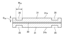
- FIG. 4 is a cross-sectional view taken along line AA in FIG. 3.
- a recess 35 is formed on the outer peripheral surface 31s of the positive electrode mixture layer 31 in an area where the tape 50 and the electrode body 14 overlap in the radial direction.
- a recess 45 is formed on the outer peripheral surface 41s of the negative electrode mixture layer 41 in an area where the tape 50 and the electrode body 14 overlap in the radial direction.
- the outer peripheral surfaces 31s, 41s of each mixture layer refer to the surface located at the outermost radial position among the outer winding surfaces 31a, 41a facing the outside of the electrode body 14.
- the exposed portion 42 of the negative electrode 12 is formed to be slightly longer than the perimeter of the outer peripheral surface 14s of the electrode body 14. Therefore, the end of the winding 41x of the outer winding surface 41a of the negative electrode mixture layer 41 is located two turns from the end of the winding 12x of the negative electrode 12. On the other hand, the end of the winding 41x of the inner winding surface 41b is located closer to the end of the winding 12x of the negative electrode 12 than the end of the winding 41x of the outer winding surface 41a. The end of the winding of the positive electrode 11 and the end of the winding 31x of the positive electrode mixture layer 31 are aligned.
- the tape 50 is attached to the outer peripheral surface 14s of the electrode body 14 across the winding end 14x of the electrode body 14, so that when the negative electrode 12 is unfolded, it extends in the longitudinal direction from the winding end side 12x of the negative electrode 12.
- FIG. 3 the area on the outer peripheral surface 14s where the portion of the tape 50 extending from the winding end side 12x is attached is shown by a virtual line.
- the length of the tape 50 is slightly shorter than the perimeter of the outer peripheral surface 14s, so there is a gap between both ends of the tape 50 in the longitudinal direction.
- the recesses 35, 45 are depressions formed in each mixture layer, and the thickness of the mixture layer is thinner in the areas where the recesses 35, 45 are formed.
- the recesses 35, 45 absorb the thickness of the tape 50 and reduce the volume change that occurs with charging and discharging in the areas that overlap radially with the tape 50. This is thought to reduce the stress acting on the edge portions of the tape 50, and effectively suppress damage to the electrode body 14.
- the recesses 35, 45 are slightly larger than the area where the tape 50 and the electrode body 14 overlap radially.
- the recesses 35, 45 may be formed in areas of the outer surface 31a, 41a of each mixture layer other than the outer surface 31s, 41s, or may be formed on the inner surface 31b, 41b.
- the recesses 35 are slightly longer than the perimeter of the outer surface 31s, and are formed from the winding end 31x beyond the outer surface 31s to the second turn.
- the recesses 45 are slightly longer than the perimeter of the outer surface 41s, and are formed from the winding end 41x beyond the outer surface 41s to the second turn.
- the recesses 35 are also formed on the inner surface 31b of the positive electrode mixture layer 31.
- a recess 45 is formed on the outer winding surface 41a of the negative electrode mixture layer 41, it is preferable to also form a recess 35 on the inner winding surface 31b of the positive electrode mixture layer 31, which faces the recess 45 via the separator 13.
- the recess 35 on the inner winding surface 31b is formed from the perspective of suppressing lithium precipitation, rather than suppressing damage to the electrode body 14.
- recesses 35 are formed on both the outer winding surface 31a and the inner winding surface 31b of the positive electrode mixture layer 31.
- the recesses 35 on each surface are formed to overlap in the thickness direction of the positive electrode 11.
- the recess 35 is preferably formed with a depth D 35 that is equal to or greater than the thickness of the tape 50. In this case, it becomes easier to absorb the thickness of the tape 50, and the effect of suppressing damage to the electrode body 14 is improved.
- the depth, width, length, etc. of the recess 45 are the same as those of the recess 35, so that the common contents of the recesses 35 and 45 will be described below using the recess 35 as an example.
- the depth D 35 of the recess 35 is equal to or greater than the thickness of the tape 50 and equal to or less than the thickness D 31 of the positive electrode mixture layer 31, and is preferably 1.0 times or more and 1.2 times or less than the thickness of the tape 50.
- a suitable example of the depth D 35 is 30 ⁇ m or more and 80 ⁇ m or less.
- the thickness of the positive electrode mixture layer 31 at the bottom of the recess 35 is thinner than that of the other region of the positive electrode mixture layer 31 where the recess 35 is not formed (hereinafter referred to as the "first region").
- the thin region formed at the bottom of the recess 35 is referred to as the "second region” of the positive electrode mixture layer 31.
- the second region is formed only on the outer peripheral surface 31s (first turn) of the positive electrode mixture layer 31 and a part of the second turn of the positive electrode mixture layer 31 adjacent to the outer peripheral surface 31s, and the other regions are the first region.
- the second region formed at the bottom of the recess 35 has substantially the same density as the first region.
- the density of the positive electrode mixture layer 31 is substantially the same throughout its entire area, and is, for example, 3.3 g/cc or more and 4.0 g/cc or less.
- the adhesion of the second region to the positive electrode core 30 is also substantially the same as the adhesion of the first region.
- the adhesion of the positive electrode mixture layer 31 to the positive electrode core 30 can be evaluated by peel strength. For this reason, it can be said that the peel strength of the positive electrode mixture layer 31 is substantially the same throughout its entire area.
- the recesses 35 are formed on both ends of the positive electrode mixture layer 31 in the width direction rather than the width direction center. That is, the recesses 35 are formed in two places separated in the width direction of the positive electrode mixture layer 31. In other words, a first region of the positive electrode mixture layer 31 is formed between the two recesses 35.
- the tape 50 is attached to both axial ends of the electrode body 14, and the width direction center of the positive electrode mixture layer 31 is an area that does not overlap with the tape 50, so by making this area the first region, it is possible to minimize capacity reduction.
- a first region is also formed between each recess 35 and both width direction ends of the positive electrode mixture layer 31.
- the recess 35 is preferably formed in a groove shape extending in the length direction of the positive electrode 11.
- the two recesses 35 are arranged parallel to each other and have substantially the same length L 35 , width W 35 , and depth D 35 .
- the recess 35 since there is an area in the circumferential center of the outer peripheral surface 14s of the electrode body 14 where the tape 50 is not attached, the recess 35 may be divided in the length direction of the positive electrode 11, but considering the positional deviation with the tape 50, it is preferable to form the recess 35 continuously.
- the recess 35 is formed continuously from the winding end side end 31x across the range of the outer peripheral surface 31s to the winding start side end in the length direction.
- the length L 35 of the recess 35 is longer than the length of the tape 50, and as a preferred example, it is 1.1 times or more and 1.5 times or less than the length of the tape 50.
- the width W35 of the recess 35 is preferably larger than the width W50 of the tape 50.
- the width W35 of the recess 35 is, for example, 1.1 times or more the width W50 of the tape 50, taking into consideration misalignment with the tape 50.
- An example of the upper limit of the width W35 of the recess 35 is 1.2 times the width W50 of the tape 50.
- the method for forming the recess 35 is not particularly limited, but one example is a method in which a positive electrode mixture slurry is applied onto the positive electrode core 30 to form a positive electrode mixture layer 31 with a certain thickness, and then a portion of the positive electrode mixture layer 31 is removed.
- the positive electrode mixture layer 31 can be removed, for example, by laser ablation.
- Laser ablation is a processing method in which a high-power laser beam is irradiated onto an object, and the constituent materials are melted, sublimated, and removed.
- the recess 35 can be formed by irradiating a desired location on the surface of the positive electrode mixture layer 31 with high-power laser beam to remove a portion of the positive electrode mixture layer 31.
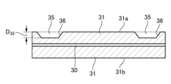
- FIGS. 5 and 6 are cross-sectional views showing modified examples of the positive electrode 11.
- the recesses 35 may be formed only on the outer winding surface 31a of the positive electrode mixture layer 31.
- the recesses 35 are formed on the outer winding surface 31a, particularly on the outer peripheral surface 31s, the effect of suppressing damage to the electrode body 14 becomes more pronounced. If the recesses 35 are formed over an excessively wide range, the capacity decreases, so forming the recesses 35 only on the outer winding surface 31a is preferable from the viewpoint of efficiently suppressing damage to the electrode body 14 while ensuring high capacity.
- the recesses 35 may be formed only on the outer peripheral surface 31s of the positive electrode mixture layer 31.
- the recess 35 is formed only on the outer winding surface 31a of the positive electrode mixture layer 31, it is preferable not to form the recess 45 on the negative electrode mixture layer 41 from the viewpoint of suppressing lithium precipitation.
- the recess 45 is formed in pairs with the recess 35 on the inner winding surface 31b of the positive electrode mixture layer 31.
- the recess 45 may be formed shallower than the recess 35. In this case, the depth of the recess 35 may be different between the outer winding surface 31a and the inner winding surface 31b, and the depth of the recess 35 on the outer winding surface 31a may be greater than the depth of the recess 35 on the inner winding surface 31b.
- the recess 35 may be tapered so that the groove width gradually narrows toward the bottom of the recess 35 (groove bottom).
- the groove wall along the length of the recess 35 is formed substantially perpendicular to the surface of the positive electrode core 30, but in the example shown in FIG. 6, the groove wall forms a slope 36 that is inclined at a predetermined angle with respect to the normal direction of the surface of the positive electrode core 30.
- the predetermined angle is, for example, 30° or more and 70° or less.
- the inclined surface 36 of the recess 35 may be formed on only one widthwise side of the recess 35, but is preferably formed on both widthwise sides.
- the groove bottom of the recess 35 is formed flat along the surface of the positive electrode core 30, and the distance between the inclined surfaces 36 along the widthwise direction of the positive electrode mixture layer 31 is set to be equal to or greater than the width W50 of the tape 50.
- the stress concentrated on the edge portion of the winding stop tape 50 can be alleviated, and damage to the electrode body 14 can be effectively suppressed.
- the tape 50 is attached to the outer peripheral surface 14s of the electrode body 14
- stress is likely to concentrate on the edge portion of the tape 50 when the volume of the electrode body 14 changes as the battery is charged and discharged, and in conventional secondary batteries, for example, wrinkles may occur in the electrodes that make up the outer peripheral surface 14s.
- wrinkles are less likely to occur in the electrodes, and damage to the electrode body 14 is sufficiently suppressed.
- the outer peripheral surface 14s of the electrode body 14 is the exposed portion 42 of the negative electrode 12, but the outer peripheral surface 14s may be the separator 13.
- Configuration 1 A secondary battery including an electrode body in which an electrode including a mixture layer is wound with a separator interposed therebetween, wherein a tape is attached to an outer peripheral surface of the electrode body to fix the end of the winding, and a recess is formed in an area of the outer peripheral surface of the mixture layer that radially overlaps the tape and the electrode body.
- Configuration 2 The secondary battery according to configuration 1, wherein the recess is formed to a depth equal to or greater than the thickness of the tape.
- Configuration 3 The secondary battery according to configuration 1 or 2, wherein the recess is a groove extending in the length direction of the electrode and formed in a tapered shape with the groove width gradually narrowing toward the groove bottom.
- Configuration 4 The secondary battery according to any one of configurations 1 to 3, wherein the mixture layer formed on the bottom of the recess has substantially the same density as the mixture layer formed in other regions other than the recess.
- Configuration 5 The secondary battery according to any one of configurations 1 to 4, wherein the electrodes include a positive electrode including a positive electrode mixture layer and a negative electrode including a negative electrode mixture layer, and the recess is formed in at least the positive electrode mixture layer.
Landscapes
- Chemical & Material Sciences (AREA)
- Chemical Kinetics & Catalysis (AREA)
- Electrochemistry (AREA)
- General Chemical & Material Sciences (AREA)
- Engineering & Computer Science (AREA)
- Manufacturing & Machinery (AREA)
- Secondary Cells (AREA)
- Battery Electrode And Active Subsutance (AREA)
Priority Applications (3)
| Application Number | Priority Date | Filing Date | Title |
|---|---|---|---|
| CN202480027119.XA CN121219874A (zh) | 2023-04-26 | 2024-04-15 | 二次电池 |
| JP2025516736A JPWO2024225089A1 (https=) | 2023-04-26 | 2024-04-15 | |
| EP24796845.6A EP4704199A1 (en) | 2023-04-26 | 2024-04-15 | Secondary battery |
Applications Claiming Priority (2)
| Application Number | Priority Date | Filing Date | Title |
|---|---|---|---|
| JP2023-072198 | 2023-04-26 | ||
| JP2023072198 | 2023-04-26 |
Publications (1)
| Publication Number | Publication Date |
|---|---|
| WO2024225089A1 true WO2024225089A1 (ja) | 2024-10-31 |
Family
ID=93256456
Family Applications (1)
| Application Number | Title | Priority Date | Filing Date |
|---|---|---|---|
| PCT/JP2024/014919 Ceased WO2024225089A1 (ja) | 2023-04-26 | 2024-04-15 | 二次電池 |
Country Status (4)
| Country | Link |
|---|---|
| EP (1) | EP4704199A1 (https=) |
| JP (1) | JPWO2024225089A1 (https=) |
| CN (1) | CN121219874A (https=) |
| WO (1) | WO2024225089A1 (https=) |
Citations (6)
| Publication number | Priority date | Publication date | Assignee | Title |
|---|---|---|---|---|
| JP2009199974A (ja) | 2008-02-25 | 2009-09-03 | Panasonic Corp | 非水系二次電池用電極群とそれを用いた二次電池 |
| JP2014053241A (ja) * | 2012-09-10 | 2014-03-20 | Toyota Motor Corp | 巻回型非水電解質二次電池およびその製造方法 |
| WO2021049471A1 (ja) * | 2019-09-11 | 2021-03-18 | 三洋電機株式会社 | 非水電解質二次電池 |
| WO2021187348A1 (ja) * | 2020-03-19 | 2021-09-23 | 三洋電機株式会社 | 非水電解質二次電池 |
| JP2022079876A (ja) * | 2020-11-17 | 2022-05-27 | プライムプラネットエナジー&ソリューションズ株式会社 | 非水電解液二次電池および非水電解液二次電池の製造方法 |
| JP2022152423A (ja) * | 2021-03-29 | 2022-10-12 | 三洋電機株式会社 | 円筒形電池 |
-
2024
- 2024-04-15 JP JP2025516736A patent/JPWO2024225089A1/ja active Pending
- 2024-04-15 CN CN202480027119.XA patent/CN121219874A/zh active Pending
- 2024-04-15 EP EP24796845.6A patent/EP4704199A1/en active Pending
- 2024-04-15 WO PCT/JP2024/014919 patent/WO2024225089A1/ja not_active Ceased
Patent Citations (6)
| Publication number | Priority date | Publication date | Assignee | Title |
|---|---|---|---|---|
| JP2009199974A (ja) | 2008-02-25 | 2009-09-03 | Panasonic Corp | 非水系二次電池用電極群とそれを用いた二次電池 |
| JP2014053241A (ja) * | 2012-09-10 | 2014-03-20 | Toyota Motor Corp | 巻回型非水電解質二次電池およびその製造方法 |
| WO2021049471A1 (ja) * | 2019-09-11 | 2021-03-18 | 三洋電機株式会社 | 非水電解質二次電池 |
| WO2021187348A1 (ja) * | 2020-03-19 | 2021-09-23 | 三洋電機株式会社 | 非水電解質二次電池 |
| JP2022079876A (ja) * | 2020-11-17 | 2022-05-27 | プライムプラネットエナジー&ソリューションズ株式会社 | 非水電解液二次電池および非水電解液二次電池の製造方法 |
| JP2022152423A (ja) * | 2021-03-29 | 2022-10-12 | 三洋電機株式会社 | 円筒形電池 |
Non-Patent Citations (1)
| Title |
|---|
| See also references of EP4704199A1 |
Also Published As
| Publication number | Publication date |
|---|---|
| JPWO2024225089A1 (https=) | 2024-10-31 |
| EP4704199A1 (en) | 2026-03-04 |
| CN121219874A (zh) | 2025-12-26 |
Similar Documents
| Publication | Publication Date | Title |
|---|---|---|
| JP5214543B2 (ja) | 二次電池 | |
| JP7187481B2 (ja) | 非水電解質二次電池 | |
| JP6684000B2 (ja) | 角形二次電池 | |
| US11824166B2 (en) | Secondary battery | |
| JP6682758B2 (ja) | 蓄電素子 | |
| JP2004356085A (ja) | ジェリーロール型の電極組立体とこれを採用した二次電池 | |
| KR20110137905A (ko) | 변형된 구조의 보호테이프를 포함하는 전지셀 및 이를 포함하고 있는 전지모듈 | |
| JP7734325B2 (ja) | 蓄電装置 | |
| JP2020144998A (ja) | 蓄電素子 | |
| WO2024225089A1 (ja) | 二次電池 | |
| WO2023210640A1 (ja) | 二次電池 | |
| WO2022065097A1 (ja) | 密閉電池 | |
| EP4704247A1 (en) | Cylindrical battery | |
| WO2026070988A1 (ja) | 二次電池及び二次電池用正極 | |
| JP7554932B2 (ja) | 電気化学セルとその製造方法 | |
| WO2025094570A1 (ja) | 二次電池 | |
| US20250316798A1 (en) | Secondary battery | |
| JP2020144996A (ja) | 蓄電素子および蓄電素子の製造方法 | |
| US20250323360A1 (en) | Square battery | |
| EP4700875A1 (en) | Battery | |
| WO2024181045A1 (ja) | 二次電池 | |
| JP2020170639A (ja) | 積層型電池 | |
| WO2026070869A1 (ja) | 二次電池及び二次電池用正極 | |
| WO2025192233A1 (ja) | 二次電池 | |
| WO2025070189A1 (ja) | 円筒形電池 |
Legal Events
| Date | Code | Title | Description |
|---|---|---|---|
| 121 | Ep: the epo has been informed by wipo that ep was designated in this application |
Ref document number: 24796845 Country of ref document: EP Kind code of ref document: A1 |
|
| ENP | Entry into the national phase |
Ref document number: 2025516736 Country of ref document: JP Kind code of ref document: A |
|
| WWE | Wipo information: entry into national phase |
Ref document number: 2025516736 Country of ref document: JP |
|
| WWE | Wipo information: entry into national phase |
Ref document number: 202547101617 Country of ref document: IN |
|
| WWE | Wipo information: entry into national phase |
Ref document number: 2024796845 Country of ref document: EP |
|
| NENP | Non-entry into the national phase |
Ref country code: DE |
|
| WWP | Wipo information: published in national office |
Ref document number: 202547101617 Country of ref document: IN |
|
| ENP | Entry into the national phase |
Ref document number: 2024796845 Country of ref document: EP Effective date: 20251126 |
|
| ENP | Entry into the national phase |
Ref document number: 2024796845 Country of ref document: EP Effective date: 20251126 |
|
| ENP | Entry into the national phase |
Ref document number: 2024796845 Country of ref document: EP Effective date: 20251126 |
|
| ENP | Entry into the national phase |
Ref document number: 2024796845 Country of ref document: EP Effective date: 20251126 |
|
| ENP | Entry into the national phase |
Ref document number: 2024796845 Country of ref document: EP Effective date: 20251126 |
|
| ENP | Entry into the national phase |
Ref document number: 2024796845 Country of ref document: EP Effective date: 20251126 |
|
| ENP | Entry into the national phase |
Ref document number: 2024796845 Country of ref document: EP Effective date: 20251126 |
|
| ENP | Entry into the national phase |
Ref document number: 2024796845 Country of ref document: EP Effective date: 20251126 |
|
| ENP | Entry into the national phase |
Ref document number: 2024796845 Country of ref document: EP Effective date: 20251126 |
|
| WWP | Wipo information: published in national office |
Ref document number: 2024796845 Country of ref document: EP |