WO2024225082A1 - 情報処理方法、および情報処理装置、並びにプログラム - Google Patents
情報処理方法、および情報処理装置、並びにプログラム Download PDFInfo
- Publication number
- WO2024225082A1 WO2024225082A1 PCT/JP2024/014859 JP2024014859W WO2024225082A1 WO 2024225082 A1 WO2024225082 A1 WO 2024225082A1 JP 2024014859 W JP2024014859 W JP 2024014859W WO 2024225082 A1 WO2024225082 A1 WO 2024225082A1
- Authority
- WO
- WIPO (PCT)
- Prior art keywords
- coordinate system
- camera
- image
- gps
- information processing
- Prior art date
- Legal status (The legal status is an assumption and is not a legal conclusion. Google has not performed a legal analysis and makes no representation as to the accuracy of the status listed.)
- Ceased
Links
Images


Classifications
-
- G—PHYSICS
- G01—MEASURING; TESTING
- G01C—MEASURING DISTANCES, LEVELS OR BEARINGS; SURVEYING; NAVIGATION; GYROSCOPIC INSTRUMENTS; PHOTOGRAMMETRY OR VIDEOGRAMMETRY
- G01C15/00—Surveying instruments or accessories not provided for in groups G01C1/00 - G01C13/00
-
- G—PHYSICS
- G01—MEASURING; TESTING
- G01C—MEASURING DISTANCES, LEVELS OR BEARINGS; SURVEYING; NAVIGATION; GYROSCOPIC INSTRUMENTS; PHOTOGRAMMETRY OR VIDEOGRAMMETRY
- G01C21/00—Navigation; Navigational instruments not provided for in groups G01C1/00 - G01C19/00
- G01C21/26—Navigation; Navigational instruments not provided for in groups G01C1/00 - G01C19/00 specially adapted for navigation in a road network
-
- G—PHYSICS
- G06—COMPUTING OR CALCULATING; COUNTING
- G06T—IMAGE DATA PROCESSING OR GENERATION, IN GENERAL
- G06T19/00—Manipulating three-dimensional [3D] models or images for computer graphics
-
- G—PHYSICS
- G08—SIGNALLING
- G08G—TRAFFIC CONTROL SYSTEMS
- G08G1/00—Traffic control systems for road vehicles
- G08G1/005—Traffic control systems for road vehicles including pedestrian guidance indicator
Definitions
- the present disclosure relates to an information processing method, an information processing device, and a program. More specifically, the present disclosure relates to an information processing method, an information processing device, and a program that display a azimuth axis indicating a direction on an image captured by a camera, position information of a feature point within the captured image, and the like.
- the image displayed on the display unit changes significantly depending on changes in the camera's attitude, making it difficult to accurately display the direction and distance measured using a geomagnetic sensor or distance measurement sensor on such a changing image.
- Patent Document 1 JP 2019-128350 A is a conventional technology that discloses a configuration in which an image is captured using a camera equipped with multiple imaging units, i.e., a stereo camera, and the captured image is analyzed to calculate the distance to an object in the captured image.
- a stereo camera i.e., a stereo camera
- the configuration disclosed in this prior art requires a stereo camera, and cannot be applied to a configuration using a monocular camera.
- the present disclosure has been made in consideration of the above-mentioned problems, and aims to provide an information processing method, an information processing device, and a program that make it possible to superimpose information such as orientation information and the position and height of each object on an image captured by a monocular camera.
- a first aspect of the present disclosure is a method for manufacturing a semiconductor device comprising: an image display step of displaying an image captured by a camera attached to the device; A camera attitude calculation step of calculating a camera attitude on a local coordinate system corresponding to a device capable of orientation analysis attached to the apparatus;
- the information processing method includes a azimuth axis display step in which the orientation of the display image displayed in the image display step is analyzed from the camera orientation calculated in the camera orientation calculation step, and an azimuth axis indicating the orientation is superimposed on the display image.
- a second aspect of the present disclosure is a display unit that displays an image captured by a camera attached to the information processing device; a data processing unit that displays a direction axis on the display image of the display unit in a superimposed manner;
- the data processing unit includes: A camera attitude calculation process for calculating a camera attitude on a local coordinate system corresponding to a device capable of orientation analysis attached to the information processing device;
- the information processing device executes a azimuth axis display process that analyzes the orientation of the display image from the calculated camera attitude and superimposes an azimuth axis on the display image on the display unit.
- a third aspect of the present disclosure is A program for causing an information processing device to execute information processing
- the information processing device includes: a display unit that displays an image captured by a camera attached to the information processing device; a data processing unit that displays a direction axis on the display image of the display unit in a superimposed manner;
- the program causes the data processing unit to A camera attitude calculation process for calculating a camera attitude on a local coordinate system corresponding to a device capable of orientation analysis attached to the information processing device;
- the program executes a process of displaying a azimuth axis by analyzing the azimuth of the display image from the calculated camera attitude and superimposing the azimuth axis on the display image of the display unit.
- the program disclosed herein is, for example, a program that can be provided by a storage medium or a communication medium in a computer-readable format to an information processing device or computer system capable of executing various program codes.
- a program that can be provided by a storage medium or a communication medium in a computer-readable format to an information processing device or computer system capable of executing various program codes.
- a system refers to a logical collective configuration of multiple devices, and is not limited to devices that are located within the same housing.
- a method and device are realized in which an orientation axis (N, E) and three-dimensional position information (N, E, Z) of a feature point are superimposed on an image captured by a camera and displayed on a display unit.
- the information processing device has a display unit that displays an image captured by a camera attached to the information processing device, and a data processing unit that displays an orientation axis indicating the orientation on the display image.
- the data processing unit executes a camera orientation calculation process that calculates the camera orientation on a local coordinate system corresponding to a device such as a GPS sensor, and an orientation axis display process that analyzes the orientation of the display image from the calculated camera orientation and displays the orientation axis on the display image.
- the data processing unit displays three-dimensional position information in association with feature points on the display image.
- This configuration realizes a method and device for superimposing and displaying an orientation axis (N, E) and three-dimensional position information (N, E, Z) of a feature point on an image captured by a camera and displayed on a display unit. It should be noted that the effects described in this specification are merely examples and are not limiting, and additional effects may also be provided.
- FIG. 2 is a diagram illustrating an overview of a process executed by an information processing device according to the present disclosure.
- 1 is a diagram illustrating an overview of a process executed by an information processing device according to the present disclosure.
- 1 is a diagram illustrating an overview of a process executed by an information processing device according to the present disclosure.
- FIG. 2 is a diagram illustrating an overview of a process executed by an information processing device according to the present disclosure.
- FIG. 2 is a diagram illustrating an overview of a process executed by an information processing device according to the present disclosure.
- 1 is a diagram illustrating an overview of a process executed by an information processing device according to the present disclosure.
- FIG. 2 is a diagram illustrating an overview of a process executed by an information processing device according to the present disclosure.
- FIG. 1 is a diagram illustrating an overview of a process executed by an information processing device according to the present disclosure.
- FIG. 2 is a diagram illustrating an overview of a process executed by an information processing device according to the present disclosure.
- FIG. 1 is a diagram illustrating a configuration of an information processing device according to the present disclosure.
- 1 is a diagram illustrating a coordinate system used by an information processing device of the present disclosure.
- 1A and 1B are diagrams illustrating a posture transformation matrix (rotation matrix) between different coordinate systems.
- FIG. 2 is a diagram illustrating a flowchart illustrating a sequence of processing executed by an information processing device of the present disclosure.
- 1 is a diagram illustrating processing executed by a data processing unit of an information processing device according to the present disclosure.
- FIG. 1 is a diagram illustrating processing executed by a data processing unit of an information processing device according to the present disclosure.
- FIG. 1 is a diagram illustrating processing executed by a data processing unit of an information processing device according to the present disclosure.
- FIG. 1 is a diagram illustrating processing executed by a data processing unit of an information processing device according to the present disclosure.
- FIG. 1 is a diagram illustrating processing executed by a data processing unit of an information processing device according to the present
- FIG. 2 is a diagram illustrating data stored in a storage unit of an information processing device according to the present disclosure.
- FIG. 1 is a diagram illustrating processing executed by a data processing unit of an information processing device according to the present disclosure.
- FIG. 1 is a diagram illustrating processing executed by a data processing unit of an information processing device according to the present disclosure.
- FIG. 1 is a diagram illustrating processing executed by a data processing unit of an information processing device according to the present disclosure.
- FIG. 1 is a diagram illustrating processing executed by a data processing unit of an information processing device according to the present disclosure.
- FIG. 1 is a diagram illustrating processing executed by a data processing unit of an information processing device according to the present disclosure.
- FIG. FIG. 2 is a diagram illustrating camera internal parameters.
- FIG. 1 is a diagram illustrating processing executed by a data processing unit of an information processing device according to the present disclosure.
- FIG. 1 is a diagram illustrating processing executed by a data processing unit of an information processing device according to the present disclosure.
- FIG. 1 is a diagram illustrating processing executed by a data processing unit of an information processing device according to the present disclosure.
- FIG. 1 is a diagram illustrating processing executed by a data processing unit of an information processing device according to the present disclosure.
- FIG. 1 is a diagram illustrating processing executed by a data processing unit of an information processing device according to the present disclosure.
- FIG. 1 is a diagram illustrating processing executed by a data processing unit of an information processing device according to the present disclosure.
- FIG. 1 is a diagram illustrating processing executed by a data processing unit of an information processing device according to the present disclosure.
- FIG. 1 is a diagram illustrating processing executed by a data processing unit of an information processing device according to the present disclosure.
- FIG. 1 is a diagram illustrating processing executed by a data processing unit of an information processing device according to the present disclosure.
- FIG. 1 is a diagram illustrating processing executed by a data processing unit of an information processing device according to the present disclosure.
- FIG. 1 is a diagram illustrating processing executed by a data processing unit of an information processing device according to the present disclosure.
- FIG. 1 is a diagram illustrating processing executed by a data processing unit of an information processing device according to the present disclosure.
- FIG. 11 is a diagram illustrating an example of display data displayed on a display unit of an information processing device according to the present disclosure.
- 11 is a diagram illustrating an example of display data displayed on a display unit of an information processing device according to the present disclosure.
- 11 is a diagram illustrating an example of display data displayed on a display unit of an information processing device according to the present disclosure.
- FIG. 11 is a diagram illustrating a configuration of an information processing device according to a second embodiment of the present disclosure.
- FIG. 11 is a diagram illustrating a coordinate system used by an information processing device according to a second embodiment of the present disclosure.
- FIG. 11 is a diagram illustrating a flowchart for explaining a sequence of a process executed by an information processing device according to a second embodiment of the present disclosure.
- FIG. 11 is a diagram illustrating a process executed by a data processing unit of an information processing apparatus according to a second embodiment of the present disclosure.
- FIG. 11 is a diagram illustrating data stored in a storage unit of an information processing device according to a second embodiment of the present disclosure.
- FIG. 11 is a diagram illustrating a process executed by a data processing unit of an information processing apparatus according to a second embodiment of the present disclosure.
- FIG. 11 is a diagram illustrating a process executed by a data processing unit of an information processing apparatus according to a second embodiment of the present disclosure.
- FIG. 11 is a diagram illustrating a process executed by a data processing unit of an information processing apparatus according to a second embodiment of the present disclosure.
- FIG. 11 is a diagram illustrating a process executed by a data processing unit of an information processing apparatus according to a second embodiment of the present disclosure.
- FIG. 11 is a diagram illustrating a process executed by a data processing unit of an information processing apparatus according to a second embodiment of the present disclosure.
- FIG. 11 is a diagram illustrating a process executed by a data processing unit of an information processing apparatus according to a second embodiment of the present disclosure
- FIG. 11 is a diagram illustrating an example of display data displayed on a display unit of an information processing device according to a second embodiment of the present disclosure.
- FIG. 11 is a diagram illustrating an example of display data displayed on a display unit of an information processing device according to a second embodiment of the present disclosure.
- FIG. 11 is a diagram illustrating an example of display data displayed on a display unit of an information processing device according to a second embodiment of the present disclosure.
- FIG. 11 is a diagram illustrating a configuration of an information processing device according to a third embodiment of the present disclosure.
- FIG. 11 is a diagram illustrating a process executed by a data processing unit of an information processing apparatus according to a second embodiment of the present disclosure.
- FIG. 11 is a diagram illustrating an example of display data displayed on a display unit of an information processing device according to a second embodiment of the present disclosure.
- FIG. 13 is a diagram illustrating a coordinate system used by an information processing device according to a third embodiment of the present disclosure.
- FIG. 11 is a diagram illustrating a flowchart for explaining a sequence of a process executed by an information processing device according to a third embodiment of the present disclosure.
- FIG. 11 is a diagram illustrating a process executed by a data processing unit of an information processing apparatus according to a third embodiment of the present disclosure.
- FIG. 11 is a diagram illustrating data stored in a storage unit of an information processing device according to a third embodiment of the present disclosure.
- FIG. 11 is a diagram illustrating a process executed by a data processing unit of an information processing apparatus according to a third embodiment of the present disclosure FIG.
- FIG. 13 is a diagram illustrating a configuration of an information processing device according to a fourth embodiment of the present disclosure.
- FIG. 13 is a diagram illustrating a flowchart for explaining a sequence of a process executed by an information processing device according to a fourth embodiment of the present disclosure.
- FIG. 13 is a diagram illustrating a process executed by a data processing unit of an information processing apparatus according to a fourth embodiment of the present disclosure.
- FIG. 13 is a diagram illustrating data stored in a storage unit of an information processing device according to a fourth embodiment of the present disclosure.
- FIG. 13 is a diagram illustrating a process executed by a data processing unit of an information processing apparatus according to a fourth embodiment of the present disclosure.
- FIG. 2 is a diagram illustrating an example of a hardware configuration of an information processing device according to the present disclosure.
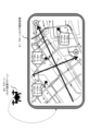
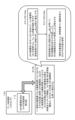
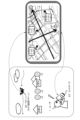
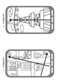
- FIG. 1 shows a state in which a user 1 holds an information processing device 10 such as a smartphone having a camera function in his/her hand and takes a picture of the outside scenery while checking a camera-captured image displayed on a display unit.
- the captured image may be either a still image or a video.
- the captured image is displayed on the display unit of the information processing device 10.
- a captured image as shown in Fig. 2 is displayed on the display unit of the information processing device 10.
- the display image shown in FIG. 2 is a camera-captured image that is displayed when an image is captured using a typical device such as a smartphone.
- the user can check the view in front of the camera by observing the image captured by the camera displayed on the display unit, but cannot tell which direction in the displayed image corresponds to north or south, east or west.
- the information processing device 10 executes a process of superimposing azimuth axes, such as an azimuth axis (N) indicating the north direction and an azimuth axis (E) indicating the east direction, on an image captured by a camera and displayed on the display unit of the information processing device 10.
- azimuth axes such as an azimuth axis (N) indicating the north direction and an azimuth axis (E) indicating the east direction
- User 1 can accurately determine the north, south, east and west directions of the camera-captured image by checking the azimuth axes on the camera-captured image displayed on the display unit of the information processing device 10.
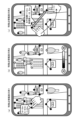
- the information processing device disclosed herein also analyzes information such as the positions and heights of various objects contained in the camera-captured image displayed on the display unit of the information processing device 10, such as houses, buildings, mountains, valleys, trees, etc., and displays this analysis data superimposed on the camera-captured image displayed on the display unit of the information processing device 10.
- FIG. 4 A specific example is shown in Figure 4.
- the information processing device disclosed herein analyzes the positions and heights of various objects contained in a camera-captured image displayed on the display unit of the information processing device 10, specifically, each of the feature points detected from the camera-captured image, and displays this analysis data by superimposing it on the camera-captured image displayed on the display unit of the information processing device 10.
- the overlay display data associated with each of the feature points as shown in FIG. 4 allows user 1 to confirm the positions and heights of various objects, such as houses, buildings, mountains, valleys, trees, etc., in the camera-captured image displayed on the display unit of the information processing device 10.
- an information processing device 10 such as a smartphone first displays an image captured by a camera on a display unit. Then, a data processing unit of the information processing device 10 performs processing to analyze the direction and the position and height of each characteristic point, and then performs processing to superimpose the direction axis and the position and height information of each characteristic point obtained as the analysis result on the camera image displayed on the display unit.
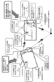
- FIG. 6 A specific example is shown in FIG.
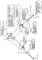
- the image shown in Fig. 6 is an image captured from the sky by the drone 20.
- the information processing device of the present disclosure displays the azimuth axis (N, E) superimposed on the image thus captured from the sky by the drone 20. Furthermore, information on the positions, heights, etc. of various objects included in the image captured by the camera, such as houses, buildings, mountains, valleys, trees, etc., is also superimposed and displayed.
- FIG. 6 is an example of an image displayed on a display unit within the drone 20, but it is also possible to display an image similar to that described with reference to FIG. 6 on the display unit of a controller 23 that controls the flight of the drone 20 on the ground, as shown in FIG. 7, for example.
- the controller 23 first receives a captured image from the drone 20 and displays it on the display unit of the controller 23. Furthermore, the data processing unit inside the controller 23 executes processing for analyzing the direction and the position and height of each characteristic point, and executes processing for superimposing the direction axis and the position and height information of each characteristic point obtained as the analysis result on the camera-captured image displayed on the display unit.
- the information processing device disclosed herein superimposes and displays the azimuth axis, the position of each feature point, and height data on the camera-captured image displayed on the display unit.
- the user can accurately grasp the north-south, east-west directions (orientations) of the camera-captured image displayed on the display unit, as well as the positions and heights of various objects contained in the camera-captured image.
- Example 1 Configuration example of information processing device of the present disclosure
- Example 2 a configuration example of the information processing apparatus according to the first embodiment of the present disclosure will be described.
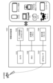
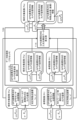
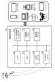
- FIG. 8 is a block diagram illustrating an example of a configuration of the information processing apparatus 100 according to the first embodiment of the present disclosure.
- the information processing device 100 according to the first embodiment of the present disclosure can be realized as various devices, such as a smartphone, a tablet terminal, a PC, a camera, a camera-equipped positioning system, a drone, a controller, etc., as shown on the right side of FIG. 8 .
- the information processing device 100 disclosed herein has a camera 101, an IMU (Inertial Measurement Unit) 102, a GPS sensor 103, a data processing unit (processor) 104, a storage unit (memory) 105, and a display unit (monitor) 106.
- IMU Inertial Measurement Unit
- GPS Global System for Mobile Communications
- processor data processing unit
- storage unit memory
- display unit monitor
- Camera 101 is, for example, a monocular camera. Note that camera 101 may be either a camera for taking still images or a camera for taking videos, or may be a camera capable of taking both still images and videos.
- the IMU (Inertial Measurement Unit) 102 is a motion sensor that measures the motion of the information processing device 100, such as the acceleration in the three x, y and z axes and the angular velocity around the three x, y and z axes.
- the GPS sensor 103 may be a conventional GPS sensor, but may also be configured to use an RTK-GPS sensor capable of highly accurate positioning.
- the RTK-GPS sensor is a positioning sensor that enables more accurate positioning by applying a relative positioning method based on signals received from four or more satellites.
- the data processing unit (processor) 104 has, for example, a processor and executes various data processing operations. Specifically, it executes the directional analysis process of the azimuth axis superimposed on the captured image described above with reference to Figures 1 to 7, the analysis process of the position and height of the characteristic points, and further the display process of this analysis data on the display unit 106.
- the storage unit (memory) 105 is made up of recording media such as RAM, ROM, and flash memory, and is used to store images captured by the camera 101, metadata corresponding to the images, and other data used for directional analysis of the azimuth axis superimposed on the captured image, and for analysis of the positions and heights of characteristic points. It is also used as a work area for data processing by the data processing unit (processor) 104.
- the display unit (monitor) 106 displays the image captured by the camera 101, and is also used to display data such as the azimuth axis, the position and height of characteristic points, etc., as previously described with reference to Figures 1 to 7.
- the display unit (monitor) 106 can also be used as a touch panel type UI, for example, and various data inputs and setting processes can be performed by user operations.
- the block diagram of the information processing device 100 shown in FIG. 8 is a block diagram showing selected main components required to perform the processing of the present disclosure.
- the information processing device 100 has various other components according to each information processing device. Specifically, it has, for example, a communication unit, a microphone, a speaker, an input unit, etc. Furthermore, if the information processing device 100 is a drone, it also has a drive unit, a flight control unit, etc.
- FIG. 9 is a diagram explaining the coordinate systems of the camera 101, IMU 102, and GPS sensor 103, which are components of a smartphone that is an example of the information processing device 100 disclosed herein, the captured image coordinate system that indicates the pixel positions of the display image displayed on the display unit 106 of the information processing device 100, and the IMU world coordinate system, which is a unique coordinate system independent of the information processing device 100.
- FIG. 1 Camera Coordinate System (C) (2) IMU local coordinate system (i) (3) GPS coordinate system (G) (4) Photographed image coordinate system (P) (5) IMU World Coordinate System (W)
- the camera coordinate system (C) is a coordinate system whose origin is the camera position (specifically, for example, the focal position) of the camera 101 attached to the information processing device 100, and whose Z axis is set in the direction of the camera optical axis.
- This camera coordinate system (C) is a coordinate system in which both the origin and the coordinate axis directions change with changes in the position and inclination of the camera 101 .
- the IMU local coordinate system (i) is a coordinate system whose origin is the IMU position of the IMU 102 attached to the information processing device 100 (specifically, for example, the center of gravity of the IMU), and whose axes are set in the same directions as the X-axis, Y-axis, and Z-axis pre-defined in the IMU sensor.
- This IMU local coordinate system (i) is a coordinate system in which both the origin and the coordinate axis directions change in accordance with changes in the position and inclination of the IMU 102 .
- the GPS coordinate system (G) is a coordinate system in which the GPS sensor position (specifically, for example, the center of gravity position of the GPS sensor) of the GPS sensor 103 attached to the information processing device 100 is set as the origin, the N (north) direction is set as the X-axis, the E (east) direction is set as the Y-axis, and the vertical downward direction is set as the Z-axis. That is, the coordinate system has three axes: two azimuth axes indicating two orthogonal directions (N, E) and an altitude axis (Z) indicating height. In this GPS coordinate system (G), only the origin of the coordinates moves with changes in the position and inclination of the GPS sensor 103. The directions of the coordinate axes (N, E, Z) do not change.
- the captured image coordinate system (P) is a coordinate system for identifying pixel positions that indicates pixel positions (u, v) in an image captured by a camera.
- This captured image coordinate system (P) is a two-dimensional coordinate system, and each pixel position (u, v) of the image represented in the captured image coordinate system (P) has a one-to-one correspondence with the XY coordinates (Xc, Yc) of the camera coordinate system (C).
- the IMU world coordinate system (W) is a unique coordinate system independent of the information processing device 100.
- the IMU world coordinate system (W) is a coordinate system in which the origin is set at a predetermined position and the Z axis is set in the vertical direction (the direction of gravitational acceleration).
- the X and Y axes are arbitrary but are in predetermined directions.
- This IMU world coordinate system (W) is an independent coordinate system in which the origin position and the direction of the coordinate axes do not change even when the position or inclination of the information processing device 100 changes.
- Data acquired by each component of the information processing device 100 of the present disclosure is data according to the respective coordinate systems.
- image data captured by the camera 101 corresponds to a three-dimensional space defined by the X, Y and Z axes of the camera coordinate system (C).
- the image data corresponds to a three-dimensional space in which the Z axis is set in the direction of the camera optical axis.
- the detection data such as acceleration and angular velocity detected by the IMU 102 becomes detection data corresponding to a three-dimensional space defined by XYZ of the IMU local coordinate system (i).
- the latitude, longitude, and altitude information detected by the GPS sensor 103 corresponds to the latitude, longitude, and altitude information of the position of the GPS sensor 103 .
- the GPS coordinate system (G) is a coordinate system that has the position of the GPS sensor 103 (specifically, for example, the center of gravity of the GPS sensor) as its origin, the N (north) direction as its X-axis, the E (east) direction as its Y-axis, and the vertical downward direction as its Z-axis.
- the origin position changes depending on the position of the GPS sensor 103, but the X-axis, Y-axis, and Z-axis are set in the N (north) direction, E (east) direction, and vertically downward, respectively, and the directions of the XYZ axes are always the same.
- the information processing device 100 disclosed herein uses a GPS coordinate system in which the axial directions of the X, Y, and Z axes do not change, and performs processing to display the X axis (N (North) azimuth axis) and Y axis (E (East) azimuth axis) that constitute the GPS coordinate system on an image captured by the camera.
- the camera position and orientation on the GPS coordinate system is calculated, and the calculated camera position and orientation on the GPS coordinate system is used to display the X-axis (N (North) azimuth axis) and Y-axis (E (East) azimuth axis) that constitute the GPS coordinate system on the camera-captured image displayed on the display unit 106 of the information processing device 100.
- attitude transformation matrix rotation matrix
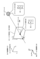
- the attitude transformation matrix (rotation matrix) will be described with reference to FIG. 10 shows two different coordinate systems, coordinate system a and coordinate system b.
- the three axis directions of Xa, Ya, and Za constituting coordinate system a and the three axis directions of Xb, Yb, and Zb constituting coordinate system b are set in different directions.
- coordinate system b has an inclined attitude with respect to coordinate system a.
- a matrix indicating the orientation (directions of three axes, Xb, Yb, and Zb) of coordinate system b on coordinate system a is an orientation transformation matrix (rotation matrix) a R b .
- the attitude transformation matrix (rotation matrix) a R b is a matrix that indicates the attitude (directions of three axes, Xb, Yb, and Zb) of the coordinate system b corresponding to the coordinate system a.
- the matrix indicating the orientation (directions of the three axes Xa, Ya, and Za) of the coordinate system a on the coordinate system b is the orientation transformation matrix (rotation matrix) bRa .
- the orientation transformation matrix (rotation matrix) is a matrix that defines the relative orientation (tilt) of two different coordinate systems.
- the attitude transformation matrix (rotation matrix) a R b is a matrix that indicates the relative attitude (tilt) between the camera coordinate system and the GPS coordinate system.
- the attitude transformation matrix (rotation matrix) a R b is a matrix that indicates the attitude of the camera coordinate system in the GPS coordinate system, that is, the camera attitude.
- attitude transformation matrix (rotation matrix) aRb By using this attitude transformation matrix (rotation matrix) aRb , it becomes possible to superimpose and display the X-axis (N (north) azimuth axis) and Y-axis (E (east) azimuth axis) according to the GPS coordinate system in the correct orientation on a camera-captured image, which is image data according to the camera coordinate system.
- the information processing device 100 disclosed herein uses a GPS coordinate system in which the axial directions of the X, Y, and Z axes do not change, and performs processing to display the X axis (N (North) azimuth axis) and Y axis (E (East) azimuth axis) that constitute the GPS coordinate system on the image captured by the camera.
- the camera position and orientation on the GPS coordinate system is calculated, and the calculated camera position and orientation on the GPS coordinate system is used to display the X-axis (N (north) azimuth axis) and Y-axis (E (east) azimuth axis) that constitute the GPS coordinate system on the camera-captured image displayed on the display unit 106 of the information processing device 100.
- N noth
- E east
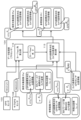
- processing according to the flow shown in Figure 11 can be executed under the control of a data processing unit (control unit) composed of a CPU and the like having a program execution function, in accordance with a program stored in the internal memory of the information processing device of the present disclosure.
- control unit composed of a CPU and the like having a program execution function
- Step S101 First, in step S101, the information processing device 100 acquires the following data at the image capture time (Tn) by the camera, namely: (a) Image captured by camera (b) IMU detection values (acceleration, angular velocity) (c) GPS sensor detection value (GPS sensor position (latitude, longitude, height)) Each of these data is obtained.
- the image captured by the camera may be either a still image or a video image.
- step S102 the information processing device 100 calculates the camera attitude (IMU world coordinate system) at the image capturing time (Tn) based on "(b) IMU detection values (acceleration, angular velocity)" at the image capturing time (Tn).
- step S102 is executed in the data processing unit 104.
- the process executed by the data processing unit 104 that is, the process of calculating the camera attitude on the IMU world coordinate system at the image capturing time (Tn) by the camera 101, will be described with reference to FIG. 12 and subsequent figures.
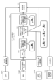
- FIG. 12 is a diagram showing processing blocks corresponding to each process executed by the data processing unit (processor) 104.
- the data processing unit (processor) 104 has an IMU filter unit 111 and an IMU world coordinate system compatible camera attitude calculation unit 112 .
- the IMU filter unit 111 inputs the detection values of the IMU 102, i.e., the acceleration and angular velocity information of the information processing device 100 to which the IMU 102 is attached, calculates the IMU attitude ( WRi ) on the IMU world coordinate system, and inputs it to the IMU world coordinate system corresponding camera attitude calculation unit 112.
- the IMU world coordinate system corresponding camera attitude calculation unit 112 inputs the IMU world coordinate system corresponding IMU attitude ( WRi ) calculated by the IMU filter unit 111 , and calculates the camera attitude in the IMU world coordinate system, i.e., the IMU world coordinate system corresponding camera attitude ( WRC ) . That is, the IMU world coordinate system corresponding camera attitude ( WRC ) corresponding to the processing result of step S102 described above is calculated.
- the IMU filter unit 111 receives the acceleration and angular velocity information of the information processing device 100, which are values detected by the IMU 102, and calculates the IMU attitude ( W R i ) on the IMU world coordinate system.
- FIG. 13 shows an information processing device 100, a camera 101 and an IMU 102 inside the information processing device 100, a camera coordinate system (C), and an IMU local coordinate system (i). Additionally, the IMU world coordinate system (W) is shown.
- the camera coordinate system (C) and the IMU local coordinate system (i) are local coordinate systems whose origin and coordinate axes change as the information processing device 100 moves.
- the IMU world coordinate system (W) is a coordinate system independent of the information processing device 100 and is a fixed coordinate system that is not linked to the movement of the information processing device 100.
- the IMU filter unit 111 first receives acceleration and angular velocity information of the information processing device 100, which are values detected by the IMU 102. These are acceleration and angular velocity information on the IMU local coordinate system (i).
- the IMU filter unit 111 calculates the IMU attitude ( W R i ) on the IMU world coordinate system, which is a coordinate system independent of the information processing device 100, based on the acceleration and angular velocity information on this IMU local coordinate system (i).
- the IMU filtering process in the IMU filter unit 111 that is, the process of calculating the IMU attitude ( W R i ) on the IMU world coordinate system based on the acceleration and angular velocity information on the IMU local coordinate system (i), is a known process.
- the IMU attitude ( WRi ) on the IMU world coordinate system is an attitude transformation matrix (rotation matrix) that indicates the attitude (tilt of each axis Xi, Yi, Zi) of the IMU local coordinate system (i) on the IMU world coordinate system (W), i.e., the tilt of IMU 102.
- the IMU attitude ( W R i ) in the IMU world coordinate system calculated by the IMU filter unit 111 is input to an IMU world coordinate system-compatible camera attitude calculation unit 112 .
- the IMU world coordinate system corresponding camera attitude calculation unit 112 inputs the IMU world coordinate system corresponding IMU attitude ( WRi ) calculated by the IMU filter unit 111 , and calculates the camera attitude in the IMU world coordinate system, i.e., the IMU world coordinate system corresponding camera attitude ( WRC ) .
- the process performed by the IMU world coordinate system camera attitude calculation unit 112 will be described with reference to FIG. 14.
- FIG. 14 shows the information processing device 100, the camera 101 and IMU 102 inside the information processing device 100, the camera coordinate system (C), and the IMU local coordinate system (i). Additionally, the IMU world coordinate system (W) is shown.
- the camera coordinate system (C) and the IMU local coordinate system (i) are local coordinate systems whose origin and coordinate axes change as the information processing device 100 moves.
- the IMU world coordinate system (W) is a coordinate system independent of the information processing device 100 and is a fixed coordinate system that is not linked to the movement of the information processing device 100.
- the IMU world coordinate system corresponding camera attitude calculation unit 112 inputs the IMU world coordinate system corresponding IMU attitude ( WRi ) calculated by the IMU filter unit 111 , and calculates the camera attitude in the IMU world coordinate system, i.e., the IMU world coordinate system corresponding camera attitude ( WRC ) , according to the following calculation formula.
- W R C ( W R i ) ⁇ ( i R C )
- ( WRC ) is an attitude transformation matrix (rotation matrix) that indicates the attitude (tilts of the Xc, Yc, and Zc axes) of the camera coordinate system (C) on the IMU world coordinate system (W), i.e., the tilt of the camera 101.
- ( WRi ) is an attitude transformation matrix (rotation matrix) indicating the attitude (tilt of each axis Xi, Yi, Zi) of the IMU local coordinate system (i) on the IMU world coordinate system (W), i.e., the tilt of the IMU 102.
- ( iRC ) is an orientation transformation matrix (rotation matrix) indicating the orientation (tilt of each of the Xc, Yc, and Zc axes) of the camera coordinate system (C) on the IMU local coordinate system (i), i.e., the tilt of the camera 101.
- the IMU attitude ( W R i ) corresponding to the IMU world coordinate system in the above equation is a value input from the IMU filter unit 111 .
- the IMU local coordinate system corresponding camera attitude ( iR C ) in the above formula is a value calculated based on the positional relationship between the camera 101 attached to the information processing device 100 and the IMU 102 and stored in the storage unit 105.
- step S102 in the flowchart shown in Figure 11, i.e., the processing of calculating the camera attitude (IMU world coordinate system) at the image capture time (Tn) based on ⁇ (b) IMU detection values (acceleration, angular velocity)'' at the image capture time (Tn).
- step S103 the process from step S103 onward in the flowchart shown in FIG. 11 will be described.
- Step S103 the information processing device 100 (a) Image captured by the camera (b) Camera attitude (IMU world coordinate system) (c) GPS sensor detection value (GPS sensor position corresponding to the GPS coordinate system) These data are stored in the storage unit (memory) 105 .
- the storage unit (memory) 105 receives and stores the camera image captured by the camera 101, GPS sensor position information acquired by the GPS sensor 103, and the IMU world coordinate system corresponding camera attitude ( WRC ) generated by the data processing unit 104 by inputting the detection information (acceleration, angular velocity) of the IMU 102.
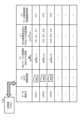
- FIG. 15 shows an example of data stored in the storage unit (memory) 105.
- the images captured by the camera 101 are moving images, and data is stored sequentially at regular frame intervals.
- data identifier For each data identifier, (a) Image captured by the camera (b) Camera attitude (IMU world coordinate system) ( WRC ) (c) GPS sensor detection value (GPS sensor position corresponding to GPS coordinate system) ( GPS P GPS ) (d) Data acquisition time (image capture time) These pieces of data are associated with each other and stored in the storage unit (memory) 105 .
- (d) data acquisition time (image capture time) is obtained from metadata set corresponding to the captured image frame of the camera 101.
- the camera-captured images are frame images that make up the video captured by the camera 101.
- Data recording processing may be performed for all image frames that make up the captured video, or data may be recorded for each specified frame.
- the camera pose is the camera pose corresponding to the IMU world coordinate system ( WRC ) .
- the GPS sensor detection value is the GPS sensor position ( GPS P GPS ) corresponding to the GPS coordinate system.
- a P b indicates the position of b in the coordinate system a.
- the GPS sensor position corresponding to the camera coordinate system (C) is ( C P GPS ).
- the camera position corresponding to the GPS coordinate system (GPS) is ( GPS P C ).
- the storage unit 105 of the information processing device 100 stores, for each image captured by the camera 101, (a) Image captured by the camera (b) Camera attitude (IMU world coordinate system) ( WRC ) (c) GPS sensor detection value (GPS sensor position corresponding to GPS coordinate system) ( GPS P GPS ) (d) Data acquisition time (image capture time) These data are recorded in association with each other.
- step S103 in the flowchart shown in FIG. 11 has been described above. Next, the process from step S104 onward in the flowchart shown in FIG. 11 will be described.
- reference image (Pr)) represents captured at time (Tr)
- the analysis target image (Pa) described in this embodiment is an image onto which the orientation coordinate axes (N, E) and the three-dimensional position information (N, E, Z) of the feature points described above with reference to Figures 1 to 7 are superimposed.
- the reference image (Pr) is a captured image stored in the storage unit (memory) 105 that was captured at a time (Tr) different from the capture time (Ta) of the image to be analyzed (Pa), and is an image used to calculate the orientation coordinate axis (N, E) to be displayed on the image to be analyzed (Pa) and the three-dimensional positions (N, E, Z) of the feature points.
- the analysis target image (Pa) is the latest captured image
- the reference image (Pr) is an image captured in the past, etc.
- An analysis target image (Pa), which is the most recently captured image, is displayed on the display unit 106 of the information processing device 100, and the orientation coordinate axes (N, E) and three-dimensional position information (N, E, Z) of the feature points described above with reference to Figures 1 to 7 are superimposed on this analysis target image (Pa).
- the combination of the image to be analyzed (Pa) and the reference image (Pr) is not limited to a combination of the most recently captured image and a previously captured image. It can be two images captured from different viewpoints that have common image features (corresponding feature points).
- Pa shooting time
- Pr reference image
- corresponding feature points are extracted by a feature point matching process that selects feature points having similar image features from two images.
- a feature point matching process for example, an ORB (Oriented FAST and Rotated BRIEF) method can be applied, and as the feature point matching process, for example, a template matching process can be applied.
- ORB Oriented FAST and Rotated BRIEF
- Step S105 Next, the information processing device 100 executes the following process in step S105. (1) The position and orientation of the camera (GPS coordinate system) at the capture time (Ta) of the image to be analyzed (Pa), and (2) The position and orientation of the camera (GPS coordinate system) at the capture time (Tr) of the reference image (Pr), Calculate these.
- the process of step S105 will be described in detail later.
- step S106 the information processing device 100 calculates three-dimensional structure data in the GPS coordinate system.
- the three-dimensional structure data includes the position and orientation (GPS coordinate system) of the camera at the time (Ta) when the image to be analyzed (Pa) was captured, and the three-dimensional positions (N, E, Z) of the feature points.
- step S106 may also include the position and orientation (GPS coordinate system) of the camera at the capture time (Tr) of the reference image (Pr) and the three-dimensional positions (N, E, Z) of the feature points.
- GPS coordinate system position and orientation
- N, E, Z three-dimensional positions
- step S107 the information processing device 100 uses the three-dimensional structure data calculated in step S106 to superimpose the orientation coordinate axis (N, E) and the three-dimensional positions (N, E, Z) of the feature points on the image to be analyzed (Pa) displayed on the display unit 106 of the information processing device 100.
- orientation coordinate axes (N, E) and the three-dimensional positions (N, E, Z) of the feature points as previously described with reference to Figures 4, 6, and 7 are superimposed on the analysis target image (Pa) displayed on the display unit 106.
- Step S105 The process described below is the process of step S105 in the flow shown in FIG. (Step S105) (1) The position and orientation of the camera (GPS coordinate system) at the capture time (Ta) of the image to be analyzed (Pa), and (2) The position and orientation of the camera (GPS coordinate system) at the capture time (Tr) of the reference image (Pr), The process of calculating these will be described in detail below.
- the information processing apparatus 100 of the present disclosure calculates the position and orientation in the GPS coordinate system of the camera 101 at the timings when the analysis target image (Pa) and the reference image (Pr) were captured. This camera position and orientation calculation process is executed by the data processing unit 104 of the information processing device 100.
- the data processing unit 104 uses the feature point matching information generated in step S104, the camera attitude (IMU world coordinate system) stored in the memory unit 105 in step S103, and the GPS sensor position (GPS coordinate system) to calculate the camera position and attitude (GPS coordinate system corresponding position and attitude) when the analysis target image (Pa) and the reference image (Pr) were captured.
- step S105 will be described in detail with reference to FIG. FIG. 16 illustrates a GPS coordinate system compatible camera position and orientation calculation unit 113 as a processing block that executes the process of step S105 in the data processing unit 104 of the information processing device 100.
- the GPS coordinate system compatible camera position and orientation calculation unit 113 For each of the analysis target image (Pa) and the reference image (Pr), GPS coordinate system corresponding GPS sensor position ( GPS P GPS ) IMU world coordinate system corresponding camera pose ( WRC ) Corresponding feature point coordinates (u, v) Enter this data and then Camera coordinate system corresponding GPS sensor position ( CGPS ), Enter this data as well.
- the GPS coordinate system-compatible GPS sensor position of the analysis target image (Pa) is shown as ( GPSa P GPSa ).
- the "a" in (GPSa) indicates that the data corresponds to the analysis target image (Pa).
- the GPS coordinate system-compatible GPS sensor position of the reference image (Pr) is shown as ( GPSR PGPSR ).
- the "r" in (GPSR) indicates that the data corresponds to the reference image (Pr).
- the IMU world coordinate system corresponding camera posture of the analysis target image (Pa) is shown as ( WRCa )
- the IMU world coordinate system corresponding camera posture of the reference image (Pr) is shown as ( WRCr ) .
- GPS coordinate system corresponding GPS sensor position GPS P GPS
- IMU world coordinate system corresponding camera pose WRC
- Corresponding feature point coordinates u, v
- the camera coordinate system corresponding GPS sensor position ( C P GPS ) is a value that can be calculated based on the positional relationship between the camera 101 attached to the information processing device 100 and the GPS sensor 103, and is calculated in the data processing unit 104. Alternatively, it may be calculated in advance and stored in the storage unit 105, and this stored data may be acquired.
- the GPS coordinate system compatible camera position and orientation calculation unit 113 inputs these data and calculates the camera position and orientation (GPS coordinate system compatible position and orientation) when the analysis target image (Pa) and the reference image (Pr) were captured. That is, as shown in FIG. 16, when the analysis target image (Pa) and the reference image (Pr) are photographed, GPS coordinate system corresponding camera position ( GPS PC ) GPS coordinate system corresponding camera attitude ( GPSRC ) Calculate these.
- GPS coordinate system corresponding camera position GPSa P Ca
- GPS coordinate system corresponding camera attitude GPSa R Ca
- GPS coordinate system corresponding camera position of reference image GPSr
- GPSr P Cr GPS coordinate system corresponding camera attitude
- the GPS coordinate system-corresponding camera orientation ( GPSaRCa ) of the image to be analyzed ( Pa ) is shown as ( GPSRCa )
- the GPS coordinate system-corresponding camera orientation ( GPSRCr ) of the reference image ( Pr ) is shown as ( GPSRCr ).
- FIG. 17 is a diagram explaining the details of the input data (excluding corresponding feature point information) and output data of the GPS coordinate system compatible camera position and orientation calculation unit 113.
- the input data (excluding corresponding feature point information) to the GPS coordinate system corresponding camera position and orientation calculation unit 113 is the following data.
- the above data is input for each of the image capture timings of the image to be analyzed (Pa) and the reference image (Pr).
- the output data of the GPS coordinate system compatible camera position and orientation calculation unit 113 is the following data.
- GPS coordinate system corresponding camera position GPS PC
- GPS coordinate system corresponding camera attitude GPSRC
- the GPS coordinate system compatible camera position and orientation calculation unit 113 calculates and outputs the above data at each image capture timing of the analysis target image (Pa) and the reference image (Pr).
- step S105 in the flow shown in FIG. (1)
- the position and orientation of the camera (GPS coordinate system) at the capture time (Tr) of the reference image (Pr) The data calculation process is carried out by sequentially executing two processes as shown in FIG.
- the GPS coordinate system compatible camera position and orientation calculation unit 113 of the data processing unit 104 of the information processing device 100 sequentially executes the following (step S105a) (step S105b).
- Step S105a An attitude transformation matrix (rotation matrix) ( GPS R W ) indicating the attitude (tilts of the Xw, Yw, and Zw axes) of the IMU world coordinate system (W) in the GPS coordinate system (GPS) is calculated (estimated).
- Step S105b Using the attitude transformation matrix (rotation matrix) ( GPS R W ), the GPS coordinate system-compatible camera position ( GPS P C ) and the GPS coordinate system-compatible camera attitude ( GPS R C ) are calculated. This process is executed as a calculation process of the positions and orientations of the cameras when capturing the analysis target image (Pa) and the reference image (Pr).
- attitude transformation matrix rotation matrix
- step S105a An attitude transformation matrix (rotation matrix) ( GPS R W ) indicating the attitude (tilts of the Xw, Yw, and Zw axes) of the IMU world coordinate system (W) in the GPS coordinate system (GPS) is calculated (estimated).
- GPS R W attitude transformation matrix
- the attitude transformation matrix (rotation matrix) ( GPS R W ) indicating the attitude of the IMU world coordinate system (W) in the GPS coordinate system (GPS) is a matrix that does not change. That is, the attitude transformation matrix (rotation matrix) ( GPS R W ) is a matrix that does not change when capturing either the analysis target image (Pa) or the reference image (Pr).
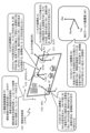
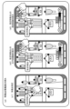
- FIG. 19 shows the position and orientation of the information processing device (smartphone) 100 when capturing an analysis target image (Pa) and a reference image (Pr).
- the slightly oblique rectangular area on the left side indicates the position and orientation of the information processing device (smartphone) 100 when the reference image (Pr) was captured.
- the rectangular area on the right side indicates the position and orientation of the information processing device (smartphone) 100 when capturing the image (Pa) to be analyzed.
- the information processing device (smartphone) 100 captures a video
- the analysis target image (Pa) is the most recently captured image in the captured video
- the reference image (Pr) corresponds to a previously captured image.
- this is just one example, and a combination of still images may also be used.
- the information processing device (smartphone) 100 at the time of capturing the analysis target image (Pa) and the reference image (Pr) shown in FIG. 19 includes a camera 101 and a GPS sensor 103, respectively.
- the image to be analyzed (Pa) is captured at a time (ta), and the reference image (Pr) is captured at a time (tr).
- FIG. 19 further shows image frames captured at two different times by the camera 101 when capturing the image to be analyzed (Pa) and the reference image (Pr) (ta, tr), and these two captured image frames capture the same feature points, i.e., corresponding feature points.
- the following three vectors t, xr , and xa are calculated on a plane defined by the camera positions and feature point positions of the analysis target image (Pa) and the reference image (Pr).
- Vector t A vector connecting the camera position (focal position) at the time (tr) of photographing the reference image (Pr) to the camera position (focal position) at the time (ta) of photographing the image to be analyzed
- Vector xr A vector connecting the positions of the feature points from the camera position (focal position) at the time (tr) of photographing the reference image
- Vector xa A vector connecting the positions of the feature points from the camera position (focal position) at the time (ta) of photographing the image to be analyzed (Pa)
- W P Ca is the camera position (focus position) in the IMU world coordinate system (W) when the analysis target image (Pa) is captured (ta).
- W P Cr is the camera position (focal position) in the IMU world coordinate system (W) at the time (tr) when the reference image (Pr) was captured.
- GPS_RW_T is a transposed matrix of an attitude transformation matrix (rotation matrix) indicating the attitude of the IMU world coordinate system (W) in the GPS coordinate system (GPS) ;
- GPS_P_GPSa is the GPS sensor position in the GPS coordinate system (GPS) at the time (ta) of capturing the analysis target image (Pa) ;
- GPS_P_GPSr is the GPS sensor position in the GPS coordinate system (GPS) at the time (tr) of capturing the reference image (Pr);
- W R Ca is the camera attitude in the IMU world coordinate system (W) when the analysis target image (Pa) is photographed (ta);
- W R Cr is the camera attitude in the IMU world coordinate system (W) when the reference image (Pr) is photographed (tr) ;
- C P GPS is the GPS sensor position in the camera coordinate system (C) (note that the GPS sensor position in the camera coordinate system (C) is the same when the analysis target image (Pa) is photographed (ta) and when the reference image (Pr) is photographed (tr) because the camera and GPS sensor are fixed to the information processing device).
- a -1 is the inverse matrix [u r , v r , 1] of the matrix A consisting of the camera internal parameters of the pinhole camera model.
- T is the transposed matrix [u a , v a , 1] of the matrix indicating the corresponding feature point positions (coordinates in the captured image coordinate system) of the reference image (Pr).
- T is the transposed matrix [u a , v a , 1] of the matrix indicating the corresponding feature point positions (coordinates in the captured image coordinate system) of the image to be analyzed (Pa).
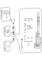
- the pinhole camera model is described below as a relational equation that defines the relationship between the three-dimensional position M of an object 201, such as a feature point in a three-dimensional space, when the object 201 is photographed by a general camera (pinhole camera), and the imaging position (imaging pixel position) m of an object image 202 of the object on the imaging plane of the camera.
- Equation 2 is an equation that indicates the correspondence between the pixel position on the camera-captured image plane of the point (m) of the object image 202 included in the camera-captured image, i.e., the position expressed by the camera coordinate system, and the three-dimensional position (M) of the object 201 in the world coordinate system. Note that in the following explanation, the ( ⁇ ) above m will be omitted.
- the m in (Equation 2) indicates a coordinate position expressed in a homogeneous coordinate system.
- the position (pixel position) of a point (m) of the object image 202 contained in the image captured by the camera is expressed by the camera image plane coordinate system.
- the camera coordinate system is a coordinate system in which the camera's focal point is the origin C, the image plane is a two-dimensional plane of Xc, Yc, and the optical axis direction (depth) is Zc, and the origin C moves with the movement of the camera.
- the three-dimensional position (M) of object 201 which is the subject of the photograph, is indicated by a world coordinate system consisting of three axes, XwYwZw, with an origin O that does not move with the movement of the camera.
- the equation showing the correspondence between the object positions in these different coordinate systems is defined as the pinhole camera model shown above (Equation 1).
- this (Equation 2) includes the following parameters: ⁇ : normalization parameter A: a matrix of camera internal parameters, Cw: camera position, Rw: camera rotation matrix, moreover,
- ⁇ is the position on the imaging plane of the camera expressed in a homogeneous coordinate system.
- ⁇ is a regularization parameter
- the matrix A consisting of the camera's internal parameters is the following determinant (Equation 3), as shown in Figure 22.
- the matrix A consisting of the camera internal parameters includes the following camera internal parameters: f: focal length ⁇ : orthogonality of image axis (ideal value is 90°) k u : Scale of the vertical axis (conversion from the scale of the 3D position to the scale of the 2D image) k v : Scale of the horizontal axis (conversion from the scale of the three-dimensional position to the scale of the two-dimensional image) (u 0 , v 0 ): image center position
- step S105a is a process of calculating (estimating) an attitude transformation matrix (rotation matrix) (GPS R W ) indicating the attitude (tilts of the Xw, Yw, and Zw axes) of the IMU world coordinate system (W) in the GPS coordinate system (GPS).
- GPS R W attitude transformation matrix
- the data processing unit 104 of the information processing device 100 of the present disclosure calculates the three vectors t, xr , and xa described with reference to Figs. 19 and 20 as described above, i.e., the following three vectors t, xr, and xa on a plane defined by the shooting camera positions and feature point positions of each image of the analysis target image (Pa) and the reference image (Pr):
- Vector t Vector connecting the camera position (focal position) at the time (tr) of the reference image (Pr) being photographed to the camera position (focal position) at the time (ta) of the image to be analyzed (Pa) being photographed
- Vector xr Vector connecting the position of the feature point from the camera position (focal position) at the time (tr) of the reference image (Pr) being photographed
- Vector xa Vector connecting the position of the feature point from the camera position (focal position) at the time (ta) of the image to be analyzed (Pa)
- GPS P GPSa is the GPS sensor position in the GPS coordinate system (GPS) at the time (ta) of capturing the image (Pa) to be analyzed
- GPS P GPSr is the GPS sensor position in the GPS coordinate system (GPS) at the time (tr) when the reference image (Pr) was captured
- C P GPS is the GPS sensor position in the camera coordinate system (C);
- W R Ca is the camera posture in the IMU world coordinate system (W) when the analysis target image (Pa) is captured (ta)
- W R Cr is the camera posture in the IMU world coordinate system (W) at the time of capturing the reference image (Pr) (tr)
- a ⁇ 1 is the inverse matrix of the matrix A consisting of the camera internal parameters of the pinhole camera model, and is a known value.
- [u r , v r , 1] T is the transpose matrix of the matrix indicating the corresponding feature point positions (coordinates in the captured image coordinate system) of the reference image (Pr)
- [u a , v a , 1] T is a transposed matrix of a matrix indicating the corresponding feature point positions (coordinates in the captured image coordinate system) of the analysis target image (Pa)
- the GPS coordinate system compatible camera position and orientation calculation unit 113 of the data processing unit 104 of the information processing device 100 calculates an orientation transformation matrix (rotation matrix) ( GPS R W ) indicating the orientation of the IMU world coordinate system (W) in the GPS coordinate system (GPS) in the previously described Figure 18 (step S105a).
- rotation matrix rotation matrix
- attitude transformation matrix (rotation matrix) ( GPSRW ) indicating the attitude of the IMU world coordinate system ( W ) in the GPS coordinate system (GPS) does not change over time and is the same matrix when capturing both the image to be analyzed (Pa) and the reference image (Pr).
- step S105b Using the attitude transformation matrix (rotation matrix) ( GPS R W ), the GPS coordinate system-compatible camera position ( GPS P C ) and the GPS coordinate system-compatible camera attitude ( GPS R C ) are calculated.
- attitude transformation matrix rotation matrix
- GPS P C GPS coordinate system-compatible camera position
- GPS R C GPS coordinate system-compatible camera attitude
- step S105b calculation processing is performed for the position and orientation of each camera when capturing the analysis target image (Pa) and the reference image (Pr).
- the GPS coordinate system-compatible camera position and orientation calculation unit 113 of the data processing unit 104 of the information processing device 100 disclosed herein calculates the GPS coordinate system-compatible camera position (GPS P C ) and the GPS coordinate system-compatible camera orientation ( GPS R C ) according to the following equations (Equation 6a) and (Equation 6b) using the orientation transformation matrix (rotation matrix) ( GPS R W ) indicating the orientation of the IMU world coordinate system (W) in the GPS coordinate system ( GPS ) calculated above (step S105a ).
- GPS- P -GPS is the GPS sensor position in the GPS coordinate system (GPS)
- GPS- R -W is the attitude transformation matrix (rotation matrix) indicating the attitude of the IMU world coordinate system (W) in the GPS coordinate system (GPS)
- WRC is the camera orientation in the IMU world coordinate system (W)
- CGPS is the GPS sensor position in the camera coordinate system (C).
- the attitude transformation matrix (rotation matrix) GPS R W indicating the attitude of the IMU world coordinate system (W) in the GPS coordinate system (GPS) is a parameter calculated in the process of step S105a described above.
- the other parameters GPS P GPS , W RC and C P GPS are all known parameters.
- the camera attitude WRC in the IMU world coordinate system (W) has been calculated in step S103 of the flow shown in FIG. 11 and stored in the storage unit 105 (see FIG. 15).
- the GPS coordinate system-compatible camera position and orientation calculation unit 113 of the data processing unit 104 of the information processing device 100 disclosed herein calculates the GPS coordinate system-compatible camera position (GPS P C ) and the GPS coordinate system-compatible camera orientation ( GPS R C ) in accordance with the above equations (Equation 6a) and (Equation 6b) using the orientation transformation matrix (rotation matrix) ( GPS R W ) indicating the orientation of the IMU world coordinate system (W) in the GPS coordinate system ( GPS ) calculated in the above-mentioned (step S105a ).
- the GPS coordinate system compatible camera position and orientation calculation unit 113 of the data processing unit 104 of the information processing device 100 calculates the following when capturing the analysis target image (Pa) and the reference image (Pr): GPS coordinate system corresponding camera position ( GPS PC ) GPS coordinate system corresponding camera attitude ( GPSRC ) Calculate these.
- step S105 of the flow shown in FIG. 11 is executed.
- step S106 is the details of step S106 in the flow shown in FIG. 11, that is, the process of calculating three-dimensional structure data in the GPS coordinate system.
- the three-dimensional structure data calculated in step S106 includes the position and orientation (GPS coordinate system) of the camera at the capture time (Ta) of the analysis target image (Pa) and the three-dimensional position (N, E, Z) information of the feature points.
- the calculation may also include the position and orientation (GPS coordinate system) of the camera at the capture time (Tr) of the reference image (Pr) and the three-dimensional positions (N, E, Z) of the feature points.
- Fig. 25 shows a GPS coordinate system compatible three-dimensional structure data calculation unit 114 as a processing block that executes this process.
- the input and output data of the GPS coordinate system compatible three-dimensional structure data calculation unit 114 will be explained with reference to FIG. 26.
- the GPS coordinate system compatible three-dimensional structure data calculation unit 114 in the data processing unit 104 of the information processing device 100 of the present disclosure receives the following data as input. For each of the analysis target image (Pa) and the reference image (Pr), GPS coordinate system corresponding GPS sensor position ( GPS P GPS ) IMU world coordinate system corresponding camera pose ( WRC ) Corresponding feature point coordinates (u, v) Enter these data.
- step S105 in the flow shown in FIG. 11 described above that is, when the analysis target image (Pa) and the reference image (Pr) generated by the GPS coordinate system compatible camera position and orientation calculation unit 113 of the data processing unit 104 are photographed, GPS coordinate system corresponding camera position ( GPS PC ) GPS coordinate system corresponding camera attitude ( GPSRC ) Enter these as well.
- GPS coordinate system corresponding camera position GPS PC
- GPS coordinate system corresponding camera attitude GPSRC
- a GPS coordinate system compatible three-dimensional structure data calculation unit 114 in the data processing unit 104 receives these data, and generates and outputs the following data: Of the analysis target image (Pa), (1) GPS coordinate system corresponding camera position ( GPS PC ) (2) GPS coordinate system-based camera attitude ( GPSRC ) (3) Feature point position corresponding to GPS coordinate system (coordinate (N, E, Z) position) These data correspond to the three-dimensional structure data calculated in step S106 of the flow shown in FIG.
- GPS PC GPS coordinate system corresponding camera position
- GPSRC GPS coordinate system-based camera attitude
- Feature point position corresponding to GPS coordinate system coordinate (N, E, Z) position
- GPS coordinate system corresponding camera position GPS PC
- GPS coordinate system-based camera attitude GPSRC
- the GPS coordinate system corresponding three-dimensional structure data calculation unit 114 (1) GPS coordinate system corresponding camera position ( GPS PC ) (2) GPS coordinate system-based camera attitude ( GPSRC ) These two calculated data, (3) Feature point position corresponding to GPS coordinate system (coordinate (N, E, Z) position) This data is generated and added as configuration data for the three-dimensional structure data. It should be noted that this "(3) GPS coordinate system corresponding feature point position (coordinate (N, E, Z) position)" can be calculated for multiple feature points (corresponding feature points) in an image.
- step S107 of the flow shown in FIG. 11 the data processing unit 104 uses these data to execute a process of superimposing the orientation coordinate axis (N, E) and the three-dimensional position (N, E, Z) of the feature point on the image to be analyzed (Pa) displayed on the display unit 106 of the information processing device 100.
- FIG. 27 shows a captured image frame 301 of a reference image (Pr) and a captured image frame 302 of an analysis target image (Pa).
- the information processing device (smartphone) 100 is shooting a video
- the captured image frame 302 of the image to be analyzed (Pa) is the most recent captured image in the captured video
- the captured image frame 301 of the reference image (Pr) corresponds to a past captured image.
- this is just one example, and a combination of still images taken individually may also be used.
- the captured image frame 302 of the analysis target image (Pa) and the captured image frame 301 of the reference image (Pr) have the same feature points, that is, corresponding feature point images.
- the feature point position (2D) of the photographed image frame 301 of the reference image (Pr) is (Ur, Vr) (photographed image coordinate system).
- the feature point position (2D) of the captured image frame 302 of the analysis target image (Pa) is (Ua, Va) (captured image coordinate system).
- the camera position (camera position corresponding to the GPS coordinate system) at the time when the photographed image frame 301 of the reference image (Pr) was photographed is GPS P Cr .
- the camera position (camera position corresponding to the GPS coordinate system) at the time when the captured image frame 302 of the analysis target image (Pa) was captured is GPS P Ca.
- FIG. 28 shows a captured image frame 301 of a reference image (Pr) and a captured image frame 302 of an analysis target image (Pa).
- the photographed image frame 301 of the reference image (Pr) shown in FIG. (1) Feature point positions (2D) (Ur, Vr) actually captured in a reference image (Pr), (2) Theoretical feature point mapping position (2D) (Ur', Vr') in the reference image (Pr) calculated based on the camera position and orientation at the time of capturing the reference image (Pr) and the feature point positions (3D) These two feature point positions are shown.
- the theoretical feature point mapping position (2D) (Ur', Vr') is a theoretical feature point mapping position calculated based on the camera position and orientation when the reference image (Pr) was captured and the feature point position (3D).
- the camera position (GPS coordinate system) when the reference image (Pr) was captured is GPS P Cr .
- the camera attitude (GPS coordinate system) when the reference image (Pr) was photographed is GPS R Cr .
- the GPS coordinate system corresponding three-dimensional structure data calculation unit 114 in the data processing unit 104 shown in FIG. 26 calculates the above two feature point positions, i.e., (1) Feature point positions (2D) (Ur, Vr) actually captured in a reference image (Pr), (2) Theoretical feature point mapping position (2D) (Ur', Vr') in the reference image (Pr) calculated based on the camera position and orientation at the time of capturing the reference image (Pr) and the feature point positions (3D)
- the camera attitude (GPS coordinate system) and the feature point position (GPS coordinate system) that minimize the difference (error) between these two feature point positions are calculated.
- the position (2D) of the feature point actually captured in the reference image (Pr) is (Ur, Vr).
- the theoretical feature point mapping position (2D) (Ur', Vr') in the reference image (Pr) calculated based on the camera position and orientation at the time of capturing the reference image (Pr) and the feature point positions (3D) is (Ur', Vr') which satisfies the following calculation formula (Formula 7), as shown in FIG. 29 .
- ⁇ normalization parameter A: a matrix of camera internal parameters
- GPS R Cr T Transposed matrix of the matrix indicating the camera orientation (GPS coordinate system) when the reference image (Pr) was captured
- GPS P x Three-dimensional position (GPS coordinate system) of the feature point x captured in the reference image (Pr)
- GPS P Cr Camera position when the reference image (Pr) was taken (GPS coordinate system) It is.
- the GPS coordinate system-compatible three-dimensional structure data calculation unit 114 calculates a camera attitude (GPS coordinate system) and a feature point position (GPS coordinate system) that satisfy the above formula (Formula 7) and minimizes the error ( ⁇ ) between the theoretical feature point mapping position (2D) (Ur', Vr') that satisfies the above formula (Formula 7) and the feature point position (2D) (Ur, Vr) that is actually photographed in the reference image (Pr). That is, the following formula (Formula 8):
- the camera attitude (GPS coordinate system) and feature point positions (GPS coordinate system) calculated by this process become the camera attitude in the GPS coordinate system and the feature point positions (3D positions) in the GPS coordinate system when the reference image (Pr) was captured.
- the GPS coordinate system compatible three-dimensional structure data calculation unit 114 performs the same process on the analysis target image (Pa).
- the analysis process using the captured image frame 302 of the analysis target image (Pa) will be described with reference to Figs. 30, like FIG. 27, shows a captured image frame 301 of a reference image (Pr) and a captured image frame 302 of an analysis target image (Pa).
- the captured image frame 302 of the analysis target image (Pa) shown in FIG. (1) Feature point positions (2D) (Ua, Va) actually captured in the analysis target image (Pa), (2) Theoretical feature point mapping positions (2D) (Ua', Va') in the analysis target image (Pa) calculated based on the camera position and orientation when the analysis target image (Pa) was captured and the feature point positions (3D) These two feature point positions are shown.
- the theoretical feature point mapping position (2D) (Ua', Va') is a theoretical feature point mapping position calculated based on the camera position and orientation when the analysis target image (Pa) was captured and the feature point positions (3D).
- the camera position (GPS coordinate system) when the analysis target image (Pa) was photographed is GPS PCa .
- the camera attitude (GPS coordinate system) when capturing the analysis target image (Pa) is GPS R Ca.
- the GPS coordinate system corresponding three-dimensional structure data calculation unit 114 in the data processing unit 104 shown in FIG. 26 calculates the above two feature point positions, i.e., (1) Feature point positions (2D) (Ua, Va) actually captured in the analysis target image (Pa), (2) Theoretical feature point mapping positions (2D) (Ua', Va') in the analysis target image (Pa) calculated based on the camera position and orientation when the analysis target image (Pa) was captured and the feature point positions (3D)
- the camera attitude (GPS coordinate system) and the feature point position (GPS coordinate system) that minimize the difference (error) between these two feature point positions are calculated.
- the position (2D) of the feature point actually captured in the analysis target image (Pa) is (Ua, Va).
- the theoretical feature point mapping position (2D) (Ua', Va') in the analysis target image (Pa) calculated based on the camera position and orientation at the time of capturing the analysis target image (Pa) and the feature point positions (3D) is (Ua', Va') which satisfies the following calculation formula (Formula 9), as shown in FIG. 31.
- ⁇ normalization parameter A: a matrix of camera internal parameters
- GPS R Ca T Transposed matrix of the matrix indicating the camera attitude (GPS coordinate system) when the analysis target image (Pa) was captured
- GPS P x Three-dimensional position (GPS coordinate system) of the feature point x captured in the analysis target image (Pa)
- GPS P Ca Camera position (GPS coordinate system) when the analysis target image (Pa) was captured It is.
- the GPS coordinate system-compatible three-dimensional structure data calculation unit 114 calculates a camera attitude (GPS coordinate system) and a feature point position (GPS coordinate system) that satisfy the above formula (Formula 9) and minimizes the error ( ⁇ ) between the theoretical feature point mapping position (2D) (Ua', Va') that satisfies the above formula (Formula 9) and the feature point position (2D) (Ua, Va) that is actually photographed in the analysis target image (Pa). That is, the following formula (Formula 10):
- the camera attitude (GPS coordinate system) and feature point positions (GPS coordinate system) calculated by this process become the camera attitude in the GPS coordinate system and the feature point positions (3D positions) in the GPS coordinate system when the image to be analyzed (Pa) was captured.
- the GPS coordinate system compatible three-dimensional structure data calculation unit 114 of the data processing unit 104 of the information processing device 100 of the present disclosure shown in FIG. 25 executes the process of step S106 of the flow shown in FIG. 11, i.e., the process of calculating three-dimensional structure data in the GPS coordinate system.
- the three-dimensional structure data includes the position and orientation (GPS coordinate system) of the camera at the time (Ta) when the image to be analyzed (Pa) was captured, and the three-dimensional positions (N, E, Z) of the feature points.
- step S106 in the flow shown in FIG. 11 i.e., the process of calculating the three-dimensional structure data in the GPS coordinate system, is completed, the process of step S107 in the flow shown in FIG. 11 is executed.
- step S107 the information processing device 100 uses the three-dimensional structure data calculated in step S106 to execute a process of superimposing the orientation coordinate axis (N, E) and the three-dimensional positions (N, E, Z) of the feature points on the analysis target image (Pa) displayed on the display unit 106 of the information processing device 100.
- orientation coordinate axes (N, E) and the three-dimensional positions (N, E, Z) of the feature points as previously described with reference to Figures 4, 6, and 7 are superimposed on the analysis target image (Pa) displayed on the display unit 106.
- Figure 32 shows a specific example in which the orientation coordinate axis (N, E) and the three-dimensional position (N, E, Z) of a feature point are superimposed on an image displayed on the display unit of an information processing device.
- the example shown in Fig. 32 is an image display example similar to the example previously described with reference to Fig. 1 to Fig. 4.
- An image of the front taken by a user 1 with an information processing device (smartphone) 100 is displayed on the display unit of the information processing device 100.
- the N azimuth axis indicating the north direction and the E azimuth axis indicating the east direction are displayed on the displayed image, and object position information (N, E, Z) indicating the positions of multiple photographed objects such as buildings and houses is displayed.
- the object position information (N, E, Z) corresponds to the distance (difference) from the information processing device 100 held by the user 1 .
- the distance in the N (north) direction, the distance in the E (east) direction, and the height difference (Z) are displayed in association with the object.
- the height (Z) may be configured to display the actual altitude, i.e., altitude data above sea level.
- the GPS sensor 103 of the information processing device 100 receives altitude data above sea level from GPS satellites (sea level altitude data of the GPS sensor 103 of the information processing device 100), and this data may be used to calculate the altitude above sea level of each feature point, and the calculated value may be displayed.
- the N azimuth axis, E azimuth axis, and object position information (N, E, Z) displayed on the display image are displayed using the three-dimensional structure data generated in step S106 of the flowchart previously described with reference to Figure 11.
- the display control process for the N azimuth axis, E azimuth axis, object position information (N, E, Z), and this data is executed by the data processing unit 104.
- the data processing unit 104 processes the following data generated by the GPS coordinate system compatible camera position and orientation calculation unit 113 and the GPS coordinate system compatible three-dimensional structure data calculation unit 114 described above, namely: Of the analysis target image (Pa), (1) GPS coordinate system corresponding camera position ( GPS PC ) (2) GPS coordinate system-based camera attitude ( GPSRC ) (3) Feature point position corresponding to GPS coordinate system (coordinate (N, E, Z) position) These data are input, and using the input data, the N azimuth axis and the E azimuth axis are displayed on the image being displayed on the display unit 106, and further, a process is performed to display object position information (N, E, Z).
- the data processing unit 104 (1) GPS coordinate system corresponding camera position ( GPS PC ) (2) GPS coordinate system-based camera attitude ( GPSRC ) Using this camera position and orientation information corresponding to the GPS coordinate axes, the corresponding position between the camera image being displayed on the display unit 106 and the N axis and E axis that make up the GPS coordinates, i.e., the N (north) direction and E (east) direction of the displayed image and their corresponding directions, are detected, and the N azimuth axis and E azimuth axis are displayed facing the detected directions.
- GPS PC GPS coordinate system corresponding camera position
- GPSRC GPS coordinate system-based camera attitude
- the GPS coordinate system-compatible camera attitude ( GPS R C ) is attitude information that indicates the inclination of the camera relative to the GPS coordinate axes (N, E, Z) (the inclination of the camera's three axes (Xc, Yc, Zc)). Therefore, by utilizing this GPS coordinate system-compatible camera attitude ( GPS R C ), it is possible to analyze the correspondence between the camera image being displayed on the display unit 106 and the N axis and E axis that make up the GPS coordinates.
- a display image such as that shown on the right side of Figure 32 is generated, that is, an image in which the N azimuth axis indicating the north direction, the E azimuth axis indicating the east direction, and object position information (N, E, Z) indicating the positions of multiple photographed objects such as buildings and houses are superimposed on the image captured by user 1 using the information processing device (smartphone) 100, and is displayed on the display unit 106.
- Figure 33 shows an example of an image display in which the N axis indicating the north direction, the E axis indicating the east direction, and object position information (N, E, Z) indicating the positions of multiple photographed objects such as buildings and houses are superimposed on an image captured by a drone.
- the drone 20 transmits images captured by the camera of the drone 20 to the controller 23 held by the user 1.
- the data processing unit 104 performs processing using the GPS coordinate system compatible camera position and orientation calculation unit 113 and the GPS coordinate system compatible three-dimensional structure data calculation unit 114 described above to obtain the following data, i.e., Of the analysis target image (Pa), (1) GPS coordinate system corresponding camera position ( GPS PC ) (2) GPS coordinate system corresponding camera attitude ( GPSRC ) (3) Feature point position corresponding to GPS coordinate system (coordinate (N, E, Z) position) These data are generated, and using the generated data, the N azimuth axis and the E azimuth axis are displayed on the image being displayed on the display unit 106, and further, processing is performed to display object position information (N, E, Z).
- GPS PC GPS coordinate system corresponding camera position
- GPSRC GPS coordinate system corresponding camera attitude
- the display manner of the N-axis and the E-axis is not necessarily limited to the example in which they are displayed as orthogonal straight lines. A specific example will be described with reference to FIG.
- FIG. 34(a) is an example of an image display similar to that previously described with reference to FIG. 32, in which the N-axis and E-axis are displayed perpendicular to each other on the display image.
- the example shown in Fig. 34(b) is an example in which a photographed image of a tower in front of the user is displayed.
- the N-azimuth axis is displayed as an axis pointing from the bottom to the top of the display unit.
- the E-azimuth axis is not displayed. Instead, the direction (angle) difference value with respect to the N-axis is displayed on a curved line displayed on the display information.
- the example of the information display showing the orientation of the image is not necessarily limited to the mode of displaying the orthogonal axes of the N-axis and the E-axis.
- the display mode can be specified by the user.
- the position of their intersection can be set in various ways and can be freely changed by the user. For example, it is possible to specify the center position of the camera image displayed on the display unit 106 as the intersection position of the N azimuth axis and the E azimuth axis. Alternatively, the user can specify any position within the camera-captured image displayed on the display unit 106 as the intersection position of the azimuth axes. It is also possible to specify the position of a specific object in the image captured by the camera and displayed on the display unit 106 as the intersection position of each azimuth axis.
- the display mode of the position information regarding the feature points can also be switched among a plurality of display modes, for example, by a user specification. A specific example will be described with reference to FIG.
- Feature point information display example 1 shown in FIG. 35(a) is an example in which the position information (N, E, Z) of only the feature point specified by the user is displayed. For feature points other than the user-specified feature points, the position information (N, E, Z) is not displayed.
- the user can grasp the height of each feature point, that is, the height of the object, based on the color of the feature point identification mark.
- Feature point information display example 3 shown in FIG. 35(c) is an example in which position difference data (distance data) between two feature points (two objects) specified by the user is displayed. For example, a user touches one feature point on the screen with a finger or a pen, and then drags the finger or pen to another feature point. By this process, position difference data (distance data) between the two feature points (two objects) specified by the user is displayed.
- FIG. 36 shows (d) feature point information display example 4.
- the user selects one feature point (object) in (d1), and the feature point identification marks corresponding to each feature point are displayed in different colors according to the horizontal distance or height difference between the selected feature point and other feature points.
- the user selects one feature point (object) in (d1)
- the user selects "horizontal distance” as shown in (d2).
- the color of the feature point identification mark corresponding to each feature point is set and displayed according to the horizontal distance between the feature point selected by the user and the other feature points. For example, feature points that are close in horizontal distance are displayed in yellow, those in the middle in green, and those that are far away in blue, and so on, and the feature point identification mark corresponding to each feature point is displayed in that color.
- the user selects one feature point (object) in (d1), and then selects "altitude difference" as shown in (d3).
- the color of the feature point identification mark corresponding to each feature point is set and displayed according to the altitude difference between the feature point selected by the user and the other feature points. For example, feature points with small altitude differences are displayed in yellow, those with intermediate altitude differences in green, and those with large altitude differences in blue, etc., with the feature point identification mark corresponding to each feature point being displayed.
- FIG. 37 shows an example in which the azimuth axes generated by the processing of the present disclosure are used in a navigation application.
- An actual image including the current location of the user 1 and a current location identification mark are displayed on the information processing device 100 held by the user 1 through processing of a navigation application.
- the azimuth axes (N azimuth axis, E azimuth axis) generated through processing of the present disclosure are superimposed on the actual image. This process allows the user to easily check the current location and the orientation of the surrounding environment.
- Example 2 Example using an information processing device having a distance measurement unit
- FIG. 38 shows an example of the configuration of the information processing device 100 of this embodiment 2.
- the information processing device 100 of this embodiment 2 has a camera 101, an IMU (Inertial Measurement Unit) 102, a GPS sensor 103, a data processing unit (processor) 104, a storage unit (memory) 105, a display unit (monitor) 106, and a LiDAR (distance measurement unit) 107.
- IMU Inertial Measurement Unit
- GPS sensor GPS sensor
- data processing unit processor
- storage unit memory
- display unit monitor
- LiDAR distance measurement unit
- the information processing device 100 shown in FIG. 38 has a configuration in which a LiDAR (distance measurement unit) 107 is added to the information processing device 100 shown in FIG. 8, which was previously described as the information processing device of the first embodiment.
- a LiDAR distance measurement unit
- the LiDAR (Light Detection and Ranging) 107 is a distance measurement sensor that outputs laser light and measures the distance to an obstacle by analyzing the reflected light of the laser light from the object.
- This LiDAR (distance measurement unit) 107 also measures the distance to each object using its own coordinate system.
- Figure 39 is a diagram explaining the coordinate systems of the camera 101, IMU 102, GPS sensor 103, and LiDAR (distance measurement unit) 107, which are components of the information processing device 100 in this embodiment 2, the captured image coordinate system that indicates the pixel positions of the display image displayed on the display unit 106 of the information processing device 100, and the IMU world coordinate system, which is a unique coordinate system independent of the information processing device 100.
- the diagram shown in FIG. 39 adds a LiDAR coordinate system (L) used by the LiDAR (distance measurement unit) 107 to the coordinate systems of the camera 101, IMU 102, GPS sensor 103, etc., which are components of the information processing device 100 of the first embodiment described above with reference to FIG. 9.
- L LiDAR coordinate system
- FIG. 1 Camera Coordinate System (C) (2) IMU local coordinate system (i) (3) GPS coordinate system (G) (4) Photographed image coordinate system (P) (5) IMU World Coordinate System (W) (6) LiDAR coordinate system (L)
- LiDAR coordinate system (L) is a coordinate system in which the LiDAR position of the LiDAR 107 attached to the information processing device 100 (specifically, for example, the center of gravity of the LiDAR) is set as the origin, and the Z axis is set in the direction of laser light output from the LiDAR. It is.
- This LiDAR coordinate system (L) is a coordinate system in which both the origin of the coordinates and the coordinate axis direction change as the position and inclination of LiDAR 107 change.
- processing according to the flow shown in Figure 40 can be executed under the control of a data processing unit (control unit) composed of a CPU and the like having program execution function, in accordance with a program stored in the internal memory of the information processing device of the present disclosure.
- control unit composed of a CPU and the like having program execution function
- Step S201 the information processing device 100 acquires the following data at the image capture time (Tn) by the camera, namely: (a) Image captured by camera (b) IMU detection values (acceleration, angular velocity) (c) GPS sensor detection value (GPS sensor position (latitude, longitude, height)) (d) LiDAR detection value (object distance (depth) information) Each of these data is obtained.
- the image captured by the camera may be either a still image or a video image.
- step S202 the information processing device 100 calculates the camera attitude (IMU world coordinate system) at the image capturing time (Tn) based on "(b) IMU detection values (acceleration, angular velocity)" at the image capturing time (Tn).
- step S202 is similar to the process of step S102 in the flow shown in FIG. 11 and described in the first embodiment. That is, as shown in FIG. 41, the process is executed in an IMU filter unit 111 and an IMU world coordinate system compatible camera attitude calculation unit 112 of a data processing unit (processor) 104 .
- processor data processing unit
- the IMU filter unit 111 inputs the detection values of the IMU 102, i.e., the acceleration and angular velocity information of the information processing device 100 to which the IMU 102 is attached, calculates the IMU attitude ( WRi ) on the IMU world coordinate system, and inputs it to the IMU world coordinate system corresponding camera attitude calculation unit 112.
- the IMU world coordinate system corresponding camera attitude calculation unit 112 inputs the IMU world coordinate system corresponding IMU attitude ( WRi ) calculated by the IMU filter unit 111 , and calculates the camera attitude in the IMU world coordinate system, i.e., the IMU world coordinate system corresponding camera attitude ( WRC ) . That is, the IMU world coordinate system corresponding camera attitude ( WRC ) corresponding to the processing result of step S102 described above is calculated.
- the IMU world coordinate system corresponding camera attitude calculation unit 112 inputs the IMU world coordinate system corresponding IMU attitude ( WRi ) calculated by the IMU filter unit 111 , and calculates the camera attitude in the IMU world coordinate system, i.e., the IMU world coordinate system corresponding camera attitude ( WRC ) , according to the following calculation formula.
- W R C ( W R i ) ⁇ ( i R C )
- Step S203 the information processing device 100 calculates the image capture time (Tn), (a) Image captured by the camera (b) Camera attitude (IMU world coordinate system) (c) GPS sensor detection value (GPS sensor position corresponding to the GPS coordinate system) (d) LiDAR detection value (object distance (depth) information) These data are stored in the storage unit (memory) 105 .
- the storage unit (memory) 105 inputs and stores the camera image captured by the camera 101, GPS sensor position information acquired by the GPS sensor 103, and the IMU world coordinate system corresponding camera attitude ( WRC ) generated by the data processing unit 104 by inputting the detection information (acceleration, angular velocity) of the IMU 102, and further the object distance (depth) information detected by the LiDAR 107.
- FIG. 42 shows an example of data stored in the storage unit (memory) 105.
- the images captured by the camera 101 are moving images, and data is stored sequentially at regular frame intervals.
- (a) Image captured by the camera (b) Camera attitude (IMU world coordinate system) ( WRC ) (c) GPS sensor detection value (GPS sensor position corresponding to GPS coordinate system) ( GPS P GPS ) (d) LiDAR detection value (object distance (depth) information) (e) Data acquisition time (image capture time)
- GPS sensor detection value GPS sensor position corresponding to GPS coordinate system
- GPS P GPS GPS
- LiDAR detection value object distance (depth) information
- e Data acquisition time (image capture time)
- (e) Data acquisition time (image capture time) is obtained from metadata set corresponding to the captured image frame of the camera 101.
- the camera-captured images are frame images that make up the video captured by the camera 101.
- Data recording processing may be performed for all image frames that make up the captured video, or data may be recorded for each specified frame.
- the camera pose is the camera pose corresponding to the IMU world coordinate system ( WRC ) .
- the GPS sensor detection value is the GPS sensor position ( GPS P GPS ) corresponding to the GPS coordinate system.
- the LiDAR detection value object distance (depth) information) is recorded, for example, as a depth map indicating the distance to objects within the output range of the laser light output by LiDAR 107.
- the area of the camera image captured by the camera 101 does not necessarily coincide with the output range of the laser light output by the LiDAR 107. That is, for example, the distance measurement range of LiDAR 107 may be only a part of the area of the camera captured image captured by camera 101.
- the storage unit 105 of the information processing device 100 stores, for each image captured by the camera 101, (a) Image captured by the camera (b) Camera attitude (IMU world coordinate system) ( WRC ) (c) GPS sensor detection value (GPS sensor position corresponding to GPS coordinate system) ( GPS P GPS ) (d) LiDAR detection value (object distance (depth) information) (e) Data acquisition time (image capture time) These data are recorded in association with each other.
- reference image (Pr)) represents captured at time (Tr)
- the image to be analyzed (Pa) is an image on which the orientation coordinate axes (N, E) and the three-dimensional position (N, E, Z) information of the feature points, which were previously described with reference to Figures 1 to 7, are superimposed.
- the reference image (Pr) is a captured image stored in the storage unit (memory) 105 that was captured at a time (Tr) different from the capture time (Ta) of the image to be analyzed (Pa), and is an image used to calculate the orientation coordinate axes (N, E) to be displayed on the image to be analyzed (Pa) and the three-dimensional positions (N, E, Z) of the feature points.
- the combination of the image to be analyzed (Pa) and the reference image (Pr) is not limited to a combination of the most recently captured image and a previously captured image. It can be two images captured from different viewpoints that have common image features (corresponding feature points).
- corresponding feature points are extracted by a feature point matching process that selects feature points having similar image features from two images.
- a feature point matching process for example, an ORB (Oriented FAST and Rotated BRIEF) method can be applied, and as the feature point matching process, for example, a template matching process can be applied.
- ORB Oriented FAST and Rotated BRIEF
- Step S205 Next, the information processing device 100 executes the following process in step S205. (1) The position and orientation of the camera (GPS coordinate system) at the capture time (Ta) of the image to be analyzed (Pa), and (2) The position and orientation of the camera (GPS coordinate system) at the capture time (Tr) of the reference image (Pr), Calculate these.
- the process of step S205 is similar to the process of step S105 of the flow shown in FIG. 11 of the first embodiment described above.
- GPS coordinate system compatible camera position and orientation calculation unit 113 of the data processing unit 104 For each of the analysis target image (Pa) and the reference image (Pr), GPS coordinate system corresponding GPS sensor position ( GPS P GPS ) IMU world coordinate system corresponding camera pose ( WRC ) Corresponding feature point coordinates (u, v) Camera coordinate system corresponding GPS sensor position ( CGPS ), Enter these data.
- the GPS coordinate system compatible camera position and orientation calculation unit 113 uses these data to calculate the following for each of the analysis target image (Pa) and the reference image (Pr) when they were photographed: GPS coordinate system corresponding camera position ( GPS PC ) GPS coordinate system corresponding camera attitude ( GPSRC ) Calculate these.
- GPS coordinate system corresponding camera position GPSa P Ca
- GPS coordinate system corresponding camera attitude GPSa R Ca
- GPS coordinate system corresponding camera position of reference image GPSr
- GPSr P Cr GPS coordinate system corresponding camera attitude
- step S206 the information processing device 100 calculates three-dimensional structure data in the GPS coordinate system.
- the three-dimensional structure data includes the position and orientation (GPS coordinate system) of the camera at the time (Ta) when the image to be analyzed (Pa) was captured, and the three-dimensional positions (N, E, Z) of the feature points.
- step S206 is the same as the processing in step S106 in the flow shown in FIG. 11 of the first embodiment described above.
- the GPS coordinate system compatible three-dimensional structure data calculation unit 114 in the data processing unit 104 of the information processing device 100 receives the following data: For each of the analysis target image (Pa) and the reference image (Pr), GPS coordinate system corresponding GPS sensor position ( GPS P GPS ) IMU world coordinate system corresponding camera pose ( WRC ) Corresponding feature point coordinates (u, v) Furthermore, when the analysis target image (Pa) and the reference image (Pr) generated by the GPS coordinate system compatible camera position and orientation calculation unit 113 were photographed, GPS coordinate system corresponding camera position ( GPS PC ) GPS coordinate system corresponding camera attitude ( GPSRC ) Each of these data items is input.
- a GPS coordinate system compatible three-dimensional structure data calculation unit 114 in the data processing unit 104 receives these data, and generates and outputs the following data: Of the analysis target image (Pa), (1) GPS coordinate system corresponding camera position ( GPS PC ) (2) GPS coordinate system corresponding camera attitude ( GPSRC ) (3) Feature point position corresponding to GPS coordinate system (coordinate (N, E, Z) position) These data correspond to the three-dimensional structure data calculated in step S206 of the flow shown in FIG.
- GPS PC GPS coordinate system corresponding camera position
- GPSRC GPS coordinate system corresponding camera attitude
- Feature point position corresponding to GPS coordinate system coordinate (N, E, Z) position
- Step S207 the information processing device 100 executes a process of mapping the detection value (object distance (depth)) of the LiDAR 107 into the GPS coordinate system.
- the detection value (object distance (depth)) of LiDAR107 is generated as a depth map generated according to the LiDAR coordinate system, i.e., a depth map showing the distance values of objects within the output range of the laser light output by LiDAR107.
- step S207 a process is performed to map the depth map generated according to the LiDAR coordinate system onto the GPS coordinate system. This process is executed by the data processing unit 104 of the information processing device.
- step S207 executed by the data processing unit 104 will be described with reference to FIGS.
- FIG. 45 shows a GPS coordinate system corresponding distance information calculation unit 115 which executes the process of step S207 within the data processing unit 104.
- the GPS coordinate system-based distance information calculation unit 115 receives the following data: GPS coordinate system corresponding camera position ( GPS P Ca ) of the image to be analyzed (Pa) GPS coordinate system corresponding camera attitude ( GPS R Ca ); GPS coordinate system corresponding camera position of reference image (Pr) ( GPS P Cr ) GPS coordinate system corresponding camera attitude ( GPS R Cr ) These are data generated by the GPS coordinate system compatible camera position and orientation calculation unit 113 .
- the LiDAR coordinate system compatible camera position and orientation information ( LPC , LRC ) can be calculated from the position and orientation relationship between the camera 101 attached to the information processing device 100 and the LiDAR 107 , and the calculated value can be stored in advance in the memory unit 105 and used.
- the GPS coordinate system corresponding distance information calculation unit 115 of the data processing unit 104 inputs these pieces of data and calculates the following for the analysis target image I(Pa):
- the GPS coordinate system corresponding distance (depth) information setting position ( GPS P x ) (coordinates) is calculated.
- GPS coordinate system-compatible distance (depth) information setting position ( GPS P x ) (coordinates) executed by the GPS coordinate system-compatible distance information calculation unit 115 will be described.
- the GPS coordinate system corresponding distance information calculation unit 115 executes a calculation according to the following equation (Equation 11) to calculate the GPS coordinate system corresponding distance (depth) information setting position ( GPS P x ) (coordinates).
- GPS P x GPS P C + GPS R C ⁇ L R C T ⁇ ( L P x ⁇ L P C ) (Formula 11)
- GPS PC is the GPS coordinate system corresponding camera position
- GPSRC is the GPS coordinate system corresponding camera attitude
- L R C T is the transpose matrix of the camera pose corresponding to the LiDAR coordinate system
- L P x is the LiDAR detection distance information setting position (coordinates) corresponding to the LiDAR coordinate system
- L P C is the LiDAR coordinate system corresponding camera position
- step S207 shown in Figure 40 coordinate mapping is performed to convert the coordinate position in the LiDAR coordinate system of the detection value (object distance (depth)) of LiDAR 107 into a coordinate position in the GPS coordinate system.
- the detection value (object distance (depth)) of LiDAR 107 is expanded into a coordinate position in the GPS coordinate system.
- step S208 the information processing device 100 uses the three-dimensional structure data calculated in step S206 and the detection value (object distance (depth)) of the LiDAR 107 mapped to the GPS coordinate system generated in step S207 to display the following data on the analysis target image (Pa) displayed on the display unit 106 of the information processing device 100, i.e., Orientation coordinate axis (N, E), The three-dimensional position (N, E, Z) of the feature point, Object distance (depth) information, At least one of these pieces of information is displayed in a superimposed manner.
- At least one of the data of the azimuth coordinate axis (N, E) as previously described with reference to Figures 4, 6, and 7, the three-dimensional position (N, E, Z) of the feature point, and the object distance (depth) measured by the LiDAR 107 is superimposed on the analysis target image (Pa) displayed on the display unit 106.
- FIG. 47 is a diagram showing an example of data displayed on the display unit of the information processing apparatus 100 according to the second embodiment.
- the example shown in Fig. 47 is an image display example similar to the example previously described with reference to Fig. 1 to Fig. 4.
- An image of the front taken by a user 1 with an information processing device (smartphone) 100 is displayed on the display unit of the information processing device 100.
- the N azimuth axis indicating the north direction and the E azimuth axis indicating the east direction are displayed on the displayed image
- object position information (N, E, Z) indicating the positions of multiple photographed objects such as buildings and houses is displayed.
- object distance (depth) information measured by LiDAR107 is superimposed and displayed.
- the object distance (depth) information measured by LiDAR 107 is shown as data set in such a way that the closer the object, the brighter the white, and the farther the object, the darker the black.
- the other superimposed data, the azimuth axis (N azimuth axis, E azimuth axis) and the object position information (N, E, Z), are the same data as those in the first embodiment described above.
- the data processing unit 104 processes the following data generated by the GPS coordinate system compatible camera position and orientation calculation unit 113 and the GPS coordinate system compatible three-dimensional structure data calculation unit 114 described above, namely: Of the analysis target image (Pa), (1) GPS coordinate system corresponding camera position ( GPS PC ) (2) GPS coordinate system-based camera attitude ( GPSRC ) (3) Feature point position corresponding to GPS coordinate system (coordinate (N, E, Z) position) These data are input, and using the input data, the N azimuth axis and the E azimuth axis are displayed on the image being displayed on the display unit 106, and further, a process is performed to display object position information (N, E, Z).
- the data processing unit 104 inputs the object distance (depth) information measured by the LiDAR 107 and the GPS coordinate system corresponding distance (depth) information setting position ( GPS P x ) (coordinates) calculated by the GPS coordinate system corresponding distance information calculation unit 115 described above, and uses these input data to perform a process of superimposing and displaying the GPS coordinate system corresponding distance (depth) information on the display image being displayed on the display unit 106.
- the area of the camera image captured by the camera 101 does not necessarily coincide with the output range of the laser light output by the LiDAR 107. That is, for example, the distance measurement range of LiDAR 107 may be only a part of the area of the camera captured image captured by camera 101.
- the information processing device 100 of the second embodiment performs display processing to inform the user looking at the display unit 106 of the distance measurement range of the LiDAR 107.
- display processing to inform the user looking at the display unit 106 of the distance measurement range of the LiDAR 107.
- the data processing unit 104 of the information processing device 100 of the second embodiment generates display data, for example, as shown on the right side of FIG. 48, and outputs it to the display unit 106.
- the display data shown in Figure 48 is an example in which information for identifying areas where distance (depth) information has been acquired by LiDAR 107 and areas where it has not been acquired is superimposed on the captured image displayed on the display unit 106. Areas where distance (depth) information was acquired by LiDAR 107 are shown as white areas (transparent areas), and areas where distance (depth) information was not acquired by LiDAR 107 are shown as gray areas.
- the information processing device 100 of the second embodiment can also accumulate distance measurement information from the LiDAR 107 in the memory unit 105. That is, as previously described with reference to Figure 42, it is possible to store and retain distance measurement information of LiDAR 107 for each timing at which an image is captured by camera 101 in memory unit 105.
- FIG. 49 is a diagram that explains a processing example in which an image captured by a camera mounted on drone 20 is displayed on a display unit, and distance information detected by a LiDAR mounted on drone 20 is further superimposed and displayed.
- drone 20 flies in the sky and takes images using a camera and measures distances using LiDAR at different positions at times t1 and t2.
- an image of the area photographed by the drone 20 at time t2 is displayed on the display unit of the controller. That is, an image of the area "camera image photographing area @t2" shown in FIG. 49 is displayed.
- LiDAR distance (depth) detection area @t2 the area in which distance can be measured by LiDAR is the area shown in "LiDAR distance (depth) detection area @t2" in Figure 49, which is a part of the "camera image capture area @t2".
- the controller's memory unit stores data from distance measurements performed by LiDAR at a past time (time t1).
- the distance measurement data depth map for the area shown in the figure as "LiDAR distance (depth) detection area @t1" is stored.
- the data processing unit 104 reads out the distance measurement data (depth map) of the area indicated by this "LiDAR distance (depth) detection area @t1" from the memory unit 105 and displays it on the display unit 106.
- the display unit 106 displays an image of the area photographed by the drone 20 at time t2, i.e., an image of the area "camera image photographing area @t2" shown in FIG. 49, and further, it is possible to superimpose and display distance information acquired by the LiDAR at the latest time (time t2) and distance information acquired by the LiDAR at a past time (time t1).
- FIG. 50 shows an example of the configuration of the information processing device 100 of this embodiment 3.
- the information processing device 100 of this embodiment 3 has a camera 101, an IMU (Inertial Measurement Unit) 102, a GPS sensor 103, a data processing unit (processor) 104, a storage unit (memory) 105, a display unit (monitor) 106, and a sub-GPS sensor 108.
- IMU Inertial Measurement Unit
- GPS sensor GPS sensor
- data processing unit processor
- storage unit memory
- display unit monitoror
- sub-GPS sensor 108 sub-GPS sensor
- the information processing device 100 shown in FIG. 50 has two GPS sensors in comparison with the information processing device 100 shown in FIG. 8, which was previously described as the information processing device of the first embodiment.
- the information processing device 100 of this embodiment 3 calculates the GPS coordinate system-compatible camera position and orientation using the GPS sensor 103 and the sub-GPS sensor 108, and the detection information from these two sensors, i.e., the two positioning information (N, E, Z) from two GPS sensors attached at different positions within the information processing device 100.
- FIG. 51 is a diagram explaining the coordinate systems of the camera 101, IMU 102, GPS sensor 103, and sub-GPS sensor 108, which are components of the information processing device 100 of this embodiment 3, the captured image coordinate system that indicates the pixel positions of the display image displayed on the display unit 106 of the information processing device 100, and the IMU world coordinate system, which is a unique coordinate system independent of the information processing device 100.
- the diagram shown in FIG. 51 adds a sub-GPS coordinate system (Gs) used by the sub-GPS sensor 108 to the coordinate systems of the camera 101, IMU 102, GPS sensor 103, etc., which are components of the information processing device 100 of the first embodiment described above with reference to FIG. 9.
- Gs sub-GPS coordinate system
- FIG. 51 shows the following six coordinate systems: (1) Camera Coordinate System (C) (2) IMU local coordinate system (i) (3) GPS coordinate system (G) (4) Photographed image coordinate system (P) (5) IMU World Coordinate System (W) (6) Sub-GPS coordinate system (Gs)
- Sub-GPS coordinate system is a coordinate system that has its origin at the sub-GPS sensor position (specifically, for example, the center of gravity position of the GPS sensor) of the sub-GPS sensor 108 attached to the information processing device 100, with the N (north) direction as the X-axis, the E (east) direction as the Y-axis, and the vertical downward direction as the Z-axis.
- the origin of the coordinates moves in accordance with changes in the position and inclination of the sub-GPS sensor 108.
- the directions of the coordinate axes (N, E, Z) do not change.
- processing according to the flow shown in Figure 52 can be executed under the control of a data processing unit (control unit) composed of a CPU and the like having program execution function, in accordance with a program stored in the internal memory of the information processing device of the present disclosure.
- control unit composed of a CPU and the like having program execution function
- Step S301 the information processing device 100 acquires the following data at the image capture time (Tn) by the camera, namely: (a) Image captured by camera (b) IMU detection values (acceleration, angular velocity) (c) GPS sensor detection value (GPS sensor position (latitude, longitude, height)) (d) Sub GPS sensor detection value (sub GPS sensor position (latitude, longitude, height)) Each of these data is obtained.
- the image captured by the camera may be either a still image or a video image.
- Step S302 the information processing device 100 calculates the camera attitude (IMU world coordinate system) at the image capturing time (Tn) based on "(b) IMU detection values (acceleration, angular velocity)" at the image capturing time (Tn).
- step S302 is similar to the process of step S102 in the flow shown in FIG. 11 and described in the first embodiment. That is, as shown in FIG. 53, the process is executed in an IMU filter unit 111 and an IMU world coordinate system compatible camera attitude calculation unit 112 of a data processing unit (processor) 104 .
- processor data processing unit
- the IMU filter unit 111 inputs the detection values of the IMU 102, i.e., the acceleration and angular velocity information of the information processing device 100 to which the IMU 102 is attached, calculates the IMU attitude ( WRi ) on the IMU world coordinate system, and inputs it to the IMU world coordinate system corresponding camera attitude calculation unit 112.
- the IMU world coordinate system corresponding camera attitude calculation unit 112 inputs the IMU world coordinate system corresponding IMU attitude ( WRi ) calculated by the IMU filter unit 111 , and calculates the camera attitude in the IMU world coordinate system, i.e., the IMU world coordinate system corresponding camera attitude ( WRC ) . That is, the IMU world coordinate system corresponding camera attitude ( WRC ) corresponding to the processing result of step S102 described above is calculated.
- the IMU world coordinate system corresponding camera attitude calculation unit 112 inputs the IMU world coordinate system corresponding IMU attitude ( WRi ) calculated by the IMU filter unit 111 , and calculates the camera attitude in the IMU world coordinate system, i.e., the IMU world coordinate system corresponding camera attitude ( WRC ) , according to the following calculation formula.
- W R C ( W R i ) ⁇ ( i R C )
- Step S303 Next, in step S303, the information processing device 100 calculates the image capture time (Tn), (a) Image captured by the camera (b) Camera attitude (IMU world coordinate system) (c) GPS sensor detection value (GPS sensor position corresponding to the GPS coordinate system) (d) Sub-GPS sensor detection value (sub-GPS sensor position corresponding to the sub-GPS coordinate system) These data are stored in the storage unit (memory) 105 .
- the storage unit (memory) 105 inputs and stores the camera image captured by the camera 101, GPS sensor position information acquired by the GPS sensor 103, sub-GPS sensor position information acquired by the sub-GPS sensor 108, and the IMU world coordinate system corresponding camera attitude ( WRC ) generated by the data processing unit 104 by inputting the detection information (acceleration, angular velocity) of the IMU 102.
- FIG. 54 shows an example of data stored in the storage unit (memory) 105.
- the images captured by the camera 101 are moving images, and data is stored sequentially at regular frame intervals.
- FIG. 54 for each data identifier, (a) Image captured by the camera (b) Camera attitude (IMU world coordinate system) ( WRC ) (c) GPS sensor detection value (GPS sensor position corresponding to GPS coordinate system) ( GPS P GPS ) (d) Sub-GPS sensor detection value (sub-GPS sensor position corresponding to sub-GPS coordinate system) ( GPSs P GPSs ) (e) Data acquisition time (image capture time) These pieces of data are associated with each other and stored in the storage unit (memory) 105 .
- (e) Data acquisition time (image capture time) is obtained from metadata set corresponding to the captured image frame of the camera 101.
- the camera-captured images are frame images that make up the video captured by the camera 101.
- Data recording processing may be performed for all image frames that make up the captured video, or data may be recorded for each specified frame.
- the camera pose is the camera pose corresponding to the IMU world coordinate system ( WRC ) .
- the GPS sensor detection value is the GPS sensor position ( GPS P GPS ) corresponding to the GPS coordinate system.
- the sub GPS sensor detection value is the sub GPS sensor position ( GPSs P GPSs ) corresponding to the sub GPS coordinate system.
- the storage unit 105 of the information processing device 100 stores, for each image captured by the camera 101, (a) Image captured by the camera (b) Camera attitude (IMU world coordinate system) ( WRC ) (c) GPS sensor detection value (GPS sensor position corresponding to GPS coordinate system) ( GPS P GPS ) (d) Sub-GPS sensor detection value (sub-GPS sensor position corresponding to sub-GPS coordinate system) ( GPSs P GPSs ) (e) Data acquisition time (image capture time) These data are recorded in association with each other.
- reference image (Pr)) represents captured at time (Tr)
- the image to be analyzed (Pa) is an image on which the orientation coordinate axes (N, E) and the three-dimensional position (N, E, Z) information of the feature points, which were previously described with reference to Figures 1 to 7, are superimposed.
- the reference image (Pr) is a captured image stored in the storage unit (memory) 105 that was captured at a time (Tr) different from the capture time (Ta) of the image to be analyzed (Pa), and is an image used to calculate the orientation coordinate axes (N, E) to be displayed on the image to be analyzed (Pa) and the three-dimensional positions (N, E, Z) of the feature points.
- the combination of the image to be analyzed (Pa) and the reference image (Pr) is not limited to a combination of the most recently captured image and a previously captured image. It can be two images captured from different viewpoints that have common image features (corresponding feature points).
- Pa shooting time
- Pr reference image
- corresponding feature points are extracted by a feature point matching process that selects feature points having similar image features from two images.
- a feature point matching process for example, an ORB (Oriented FAST and Rotated BRIEF) method can be applied, and as the feature point matching process, for example, a template matching process can be applied.
- ORB Oriented FAST and Rotated BRIEF
- Step S305 the information processing device 100 uses two different GPS sensor detection values to determine a camera azimuth angle corresponding to the orientation of the camera, and further calculates a yaw angle from the determined camera azimuth angle.
- GPS sensor detection value GPS sensor position corresponding to GPS coordinate system
- GPS P GPS GPS P GPS
- Sub-GPS sensor detection value sub-GPS sensor position corresponding to sub-GPS coordinate system
- GPSs P GPSs GPSs
- the GPS coordinate system has coordinate axes of (N, E, Z) with the Z direction set vertically.
- Step S306 the information processing device 100 executes the following process in step S306. (1) The position and orientation of the camera (GPS coordinate system) at the capture time (Ta) of the image to be analyzed (Pa), and (2) The position and orientation of the camera (GPS coordinate system) at the capture time (Tr) of the reference image (Pr), Calculate these.
- the process executed by the information processing apparatus 100 of the third embodiment that is, the process of calculating the GPS coordinate system-compatible camera position and orientation using two pieces of positioning information from two GPSs, will be described with reference to FIG.
- This process is executed by the data processing unit 104 of the information processing apparatus 100 of the third embodiment.
- the data processing unit 104 of this embodiment 3 has a yaw angle calculation unit 116 and a GPS coordinate system compatible camera position and orientation calculation unit 113.
- the yaw angle calculation unit 116 executes the process of step S305 described above. That is, the camera azimuth angle corresponding to the camera orientation is obtained using the detection values of the two different GPS sensors, the GPS sensor 103 and the sub GPS sensor 108, and the yaw angle is calculated from the obtained camera azimuth angle.
- the GPS coordinate system compatible camera position and orientation calculation unit 113 uses these data to calculate the following for each of the analysis target image (Pa) and the reference image (Pr) when they were photographed: GPS coordinate system corresponding camera position ( GPS PC ) GPS coordinate system corresponding camera attitude ( GPSRC ) Calculate these. It should be noted that the GPS coordinate system is a coordinate system corresponding to the GPS sensor 103 .
- GPS coordinate system corresponding camera position GPSa P Ca
- GPS coordinate system corresponding camera attitude GPSa R Ca
- GPS coordinate system corresponding camera position of reference image GPSr
- GPSr P Cr GPS coordinate system corresponding camera attitude
- step S307 the information processing device 100 calculates three-dimensional structure data in the GPS coordinate system.
- the three-dimensional structure data includes the position and orientation (GPS coordinate system) of the camera at the capture time (Ta) of the analysis target image (Pa) and the three-dimensional position (N, E, Z) information of the feature points.
- the process of step S307 is similar to the process of step S106 in the flow shown in FIG. 11 of the first embodiment described above.
- step S308 the information processing device 100 uses the three-dimensional structure data calculated in step S307 to display the following data on the analysis target image (Pa) displayed on the display unit 106 of the information processing device 100, i.e., Orientation coordinate axis (N, E), The three-dimensional position (N, E, Z) of the feature point, At least one of these pieces of information is displayed in a superimposed manner.
- the display data as described above with reference to Figures 4, 6, and 7, specifically, display data in which at least one of the data of the orientation coordinate axis (N, E) and the three-dimensional position (N, E, Z) of the feature point is superimposed on the analysis target image (Pa) displayed on the display unit 106, is generated and output to the display unit 106.
- Example 4 Example using an information processing device having a geomagnetic sensor
- Example using an information processing device having a geomagnetic sensor uses an information processing device having a geomagnetic sensor.
- FIG. 56 shows an example of the configuration of an information processing device 100 according to this embodiment 4.
- the information processing device 100 according to this embodiment 4 includes a camera 101, an IMU (Inertial Measurement Unit) 102, a GPS sensor 103, a data processing unit (processor) 104, a storage unit (memory) 105, a display unit (monitor) 106, and a geomagnetic sensor 109.
- IMU Inertial Measurement Unit
- the information processing device 100 shown in FIG. 56 has a configuration in which a geomagnetic sensor 109 is added to the information processing device 100 shown in FIG. 8, which was previously described as the information processing device of the first embodiment.
- the geomagnetic sensor 109 added to the information processing device 100 of this embodiment 4 detects the orientation of the information processing device 100. Specifically, for example, it detects the direction (camera orientation) of the camera 101 of the information processing device 100.
- processing according to the flow shown in Figure 57 can be executed under the control of a data processing unit (control unit) composed of a CPU and the like having program execution function, in accordance with a program stored in the internal memory of the information processing device of the present disclosure.
- control unit composed of a CPU and the like having program execution function
- Step S401 First, in step S401, the information processing device 100 acquires the following data at the image capture time (Tn) by the camera, namely: (a) Image captured by camera (b) IMU detection values (acceleration, angular velocity) (c) GPS sensor detection value (GPS sensor position (latitude, longitude, height)) (d) Geomagnetic sensor detection value (orientation information) Each of these data is obtained.
- the image captured by the camera may be either a still image or a video image.
- Step S402 the information processing device 100 calculates the camera attitude (IMU world coordinate system) at the image capturing time (Tn) based on "(b) IMU detection values (acceleration, angular velocity)" at the image capturing time (Tn).
- step S402 is similar to the process of step S102 in the flow shown in FIG. 11 and described in the first embodiment. That is, as shown in FIG. 58, the process is executed in an IMU filter unit 111 and an IMU world coordinate system compatible camera attitude calculation unit 112 of a data processing unit (processor) 104 .
- processor data processing unit
- the IMU filter unit 111 inputs the detection values of the IMU 102, i.e., the acceleration and angular velocity information of the information processing device 100 to which the IMU 102 is attached, calculates the IMU attitude ( WRi ) on the IMU world coordinate system, and inputs it to the IMU world coordinate system corresponding camera attitude calculation unit 112.
- the IMU world coordinate system corresponding camera attitude calculation unit 112 inputs the IMU world coordinate system corresponding IMU attitude ( WRi ) calculated by the IMU filter unit 111 , and calculates the camera attitude in the IMU world coordinate system, i.e., the IMU world coordinate system corresponding camera attitude ( WRC ) . That is, the IMU world coordinate system corresponding camera attitude ( WRC ) corresponding to the processing result of step S102 described above is calculated.
- the IMU world coordinate system corresponding camera attitude calculation unit 112 inputs the IMU world coordinate system corresponding IMU attitude ( WRi ) calculated by the IMU filter unit 111 , and calculates the camera attitude in the IMU world coordinate system, i.e., the IMU world coordinate system corresponding camera attitude ( WRC ) , according to the following calculation formula.
- W R C ( W R i ) ⁇ ( i R C )
- step S403 the information processing device 100 calculates the image capture time (Tn), (a) Image captured by the camera (b) Camera attitude (IMU world coordinate system) (c) GPS sensor detection value (GPS sensor position corresponding to the GPS coordinate system) (d) Geomagnetic sensor detection value (orientation information) These data are stored in the storage unit (memory) 105 .
- the storage unit (memory) 105 receives and stores the camera image captured by the camera 101, GPS sensor position information acquired by the GPS sensor 103, orientation information acquired by the geomagnetic sensor 109, and the IMU world coordinate system corresponding camera attitude ( WRC ) generated by the data processing unit 104 by inputting the detection information (acceleration, angular velocity ) of the IMU 102.
- FIG. 59 shows an example of data stored in the storage unit (memory) 105.
- the images captured by the camera 101 are moving images, and data is stored sequentially at regular frame intervals.
- (a) Image captured by the camera (b) Camera attitude (IMU world coordinate system) ( WRC ) (c) GPS sensor detection value (GPS sensor position corresponding to GPS coordinate system) ( GPS P GPS ) (d) Geomagnetic sensor detection value (orientation information) (e) Data acquisition time (image capture time)
- WRC Camera attitude
- GPS sensor detection value GPS sensor position corresponding to GPS coordinate system
- GPS P GPS GPS
- Geomagnetic sensor detection value orientation information
- (e) Data acquisition time (image capture time)
- (e) Data acquisition time (image capture time) is obtained from metadata set corresponding to the captured image frame of the camera 101.
- the camera-captured images are frame images that make up the video captured by the camera 101.
- Data recording processing may be performed for all image frames that make up the captured video, or data may be recorded for each specified frame.
- the camera pose is the camera pose corresponding to the IMU world coordinate system ( WRC ) .
- the GPS sensor detection value is the GPS sensor position ( GPS P GPS ) corresponding to the GPS coordinate system.
- the geomagnetic sensor detection value is information indicating, for example, the orientation of the information processing device, specifically, the orientation of the camera (camera orientation).
- the storage unit 105 of the information processing device 100 stores, for each image captured by the camera 101, (a) Image captured by the camera (b) Camera attitude (IMU world coordinate system) ( WRC ) (c) GPS sensor detection value (GPS sensor position corresponding to GPS coordinate system) ( GPS P GPS ) (d) Geomagnetic sensor detection value (orientation information) (e) Data acquisition time (image capture time) These data are recorded in association with each other.
- step S404 we will explain the processing from step S404 onwards in the flowchart shown in Figure 57.
- reference image (Pr)) represents captured at time (Tr)
- the image to be analyzed (Pa) is an image on which the orientation coordinate axes (N, E) and the three-dimensional position (N, E, Z) information of the feature points, which were previously described with reference to Figures 1 to 7, are superimposed.
- the reference image (Pr) is a captured image stored in the storage unit (memory) 105 that was captured at a time (Tr) different from the capture time (Ta) of the image to be analyzed (Pa), and is an image used to calculate the orientation coordinate axes (N, E) to be displayed on the image to be analyzed (Pa) and the three-dimensional positions (N, E, Z) of the feature points.
- the combination of the image to be analyzed (Pa) and the reference image (Pr) is not limited to a combination of the most recently captured image and a previously captured image. It can be two images captured from different viewpoints that have common image features (corresponding feature points).
- Pa shooting time
- Pr reference image
- corresponding feature points are extracted by a feature point matching process that selects feature points having similar image features from two images.
- a feature point matching process for example, an ORB (Oriented FAST and Rotated BRIEF) method can be applied, and as the feature point matching process, for example, a template matching process can be applied.
- ORB Oriented FAST and Rotated BRIEF
- step S405 the information processing device 100 uses the geomagnetic sensor detection value to determine the camera azimuth angle corresponding to the orientation of the camera, and further calculates the yaw angle from the determined camera azimuth angle.
- Geomagnetic sensor detection value (orientation information)
- the detection value of the geomagnetic sensor is used to determine the camera azimuth angle, which corresponds to the orientation of the camera, and the yaw angle is calculated from the determined camera azimuth angle.
- the GPS coordinate system has coordinate axes of (N, E, Z) with the Z direction set vertically.
- Step S406 the information processing device 100 executes the following process in step S406. (1) The position and orientation of the camera (GPS coordinate system) at the capture time (Ta) of the image to be analyzed (Pa), and (2) The position and orientation of the camera (GPS coordinate system) at the capture time (Tr) of the reference image (Pr), Calculate these.
- a process executed by the information processing apparatus 100 of the fourth embodiment that is, a process of calculating the GPS coordinate system-compatible camera position and orientation using two pieces of positioning information from two GPSs, will be described.
- This process is executed by the data processing unit 104 of the information processing apparatus 100 of the fourth embodiment.
- the data processing unit 104 of this embodiment 4 has a yaw angle calculation unit 116 and a GPS coordinate system compatible camera position and orientation calculation unit 113.
- the yaw angle calculation unit 116 executes the process of step S405 described above. That is, the camera azimuth angle corresponding to the camera direction is obtained using the azimuth information, which is the sensor detection value of the geomagnetic sensor 109, and the yaw angle is calculated from the obtained camera azimuth angle.
- the GPS coordinate system compatible camera position and orientation calculation unit 113 uses these data to calculate the following for each of the analysis target image (Pa) and the reference image (Pr) when they were photographed: GPS coordinate system corresponding camera position ( GPS PC ) GPS coordinate system corresponding camera attitude ( GPSRC ) Calculate these.
- GPS coordinate system corresponding camera position GPSa P Ca
- GPS coordinate system corresponding camera attitude GPSa R Ca
- GPS coordinate system corresponding camera position of reference image GPSr
- GPSr P Cr GPS coordinate system corresponding camera attitude
- step S407 the information processing device 100 calculates three-dimensional structure data in the GPS coordinate system.
- the three-dimensional structure data includes the position and orientation (GPS coordinate system) of the camera at the capture time (Ta) of the analysis target image (Pa) and the three-dimensional position (N, E, Z) information of the feature points.
- the process in step S407 is similar to the process in step S106 in the flow shown in FIG. 11 of the first embodiment described above.
- step S408 the information processing device 100 uses the three-dimensional structure data calculated in step S407 to display the following data on the analysis target image (Pa) displayed on the display unit 106 of the information processing device 100, i.e., Orientation coordinate axis (N, E), The three-dimensional position (N, E, Z) of the feature point, At least one of these pieces of information is displayed in a superimposed manner.
- the display data as described above with reference to Figures 4, 6, and 7, specifically, display data in which at least one of the data of the orientation coordinate axis (N, E) and the three-dimensional position (N, E, Z) of the feature point is superimposed on the analysis target image (Pa) displayed on the display unit 106, is generated and output to the display unit 106.
- a CPU (Central Processing Unit) 501 functions as a data processing unit that executes various processes according to programs stored in a ROM (Read Only Memory) 502 or a storage unit 508. For example, the CPU executes processes according to the sequences described in the above-mentioned embodiments.
- a RAM (Random Access Memory) 503 stores programs and data executed by the CPU 501.
- the CPU 501, ROM 502, and RAM 503 are connected to each other via a bus 504.
- the CPU 501 is connected to an input/output interface 505 via a bus 504, and the input/output interface 505 is connected to an input unit 506 consisting of various sensors, a camera, a switch, a keyboard, a mouse, a microphone, etc., and an output unit 507 consisting of a display, a speaker, etc.
- an input unit 506 consisting of various sensors, a camera, a switch, a keyboard, a mouse, a microphone, etc.
- an output unit 507 consisting of a display, a speaker, etc.
- the storage unit 508 connected to the input/output interface 505 is, for example, a USB memory, an SD card, a hard disk, etc., and stores the programs executed by the CPU 501 and various data.
- the communication unit 509 functions as a transmitter/receiver for data communication via a network such as the Internet or a local area network, and communicates with external devices.
- the drive 510 connected to the input/output interface 505 drives removable media 511, such as a magnetic disk, optical disk, magneto-optical disk, or semiconductor memory such as a memory card, and performs recording or reading of data.
- removable media 511 such as a magnetic disk, optical disk, magneto-optical disk, or semiconductor memory such as a memory card, and performs recording or reading of data.
- the technology disclosed in this specification can have the following configurations. (1) an image display step of displaying an image captured by a camera attached to the device; A camera attitude calculation step of calculating a camera attitude on a local coordinate system corresponding to a device capable of orientation analysis attached to the apparatus; An information processing method that executes a azimuth axis display step in which the orientation of the display image displayed in the image display step is analyzed from the camera orientation calculated in the camera orientation calculation step, and an azimuth axis indicating the orientation is superimposed on the display image.
- the device is The information processing method according to (1), wherein the device performs positioning processing based on a signal received from a satellite.
- the device is a GPS sensor;
- the information processing method according to (1) or (2), wherein the device-compatible local coordinate system is a GPS sensor coordinate system having a azimuth axis indicating a direction as a coordinate axis component.
- the camera attitude calculation step includes: a world coordinate system camera orientation calculation step of calculating a camera orientation on a world coordinate system which is a coordinate system independent of the device;
- the information processing method according to any one of (1) to (3), further comprising a step of calculating a camera attitude in a local coordinate system corresponding to the device based on the calculated camera attitude in a world coordinate system.
- the world coordinate system camera orientation calculation step includes: performing an IMU filtering process to calculate an IMU local coordinate system attitude transformation matrix that transforms the attitude of an IMU local coordinate system corresponding to the IMU into an attitude on the world coordinate system, using a detection value of an IMU attached to the device;
- the information processing method according to (4) further comprising a step of calculating the camera attitude on the world coordinate system by performing a matrix calculation using the IMU local coordinate system attitude transformation matrix calculated by the IMU filtering process.
- the camera attitude calculation step includes: a first orientation transformation matrix calculation step of calculating an orientation transformation matrix indicating a camera orientation in a world coordinate system which is a coordinate system independent of the device; a second orientation transformation matrix calculation step of calculating an orientation transformation matrix indicating an orientation of a world coordinate system on the device-corresponding local coordinate system;
- the world coordinate system The information processing method according to any one of (4) to (6), wherein the device-compatible local coordinate systems are coordinate systems having a Z axis in the vertical direction.
- the second attitude transformation matrix calculation step The displayed image is an image to be analyzed, A corresponding feature point detection process for detecting corresponding feature points corresponding to the same object from two images, a reference image captured from a different direction from the image to be analyzed; Executing a calculation process to which an epipolar geometry theory is applied using three vectors connecting the camera focal position when the analysis target image was captured, the camera focal position when the reference image was captured, and the position of the corresponding feature point;
- the information processing method further comprises: A posture transformation matrix indicating the posture of the camera on the world coordinate system; an orientation transformation matrix indicating an orientation of a world coordinate system on the device-compatible local coordinate system; An information processing method according to any one of (6) to (8), comprising a camera position calculation step of performing matrix calculation processing using a matrix indicating the device position in a camera coordinate system corresponding to the camera, to calculate the camera position on a local coordinate system corresponding to the device.
- the information processing method further comprises: a feature point detection processing step of detecting feature points from the display image; a feature point position calculation process step of calculating a feature point position in a local coordinate system corresponding to the device for each of the detected feature points;
- the feature point detection processing step includes: The displayed image is an image to be analyzed, The information processing method according to (10), further comprising the step of executing a process for detecting corresponding feature points corresponding to the same object from two images, a reference image taken from a different direction from the image to be analyzed.
- the device-specific local coordinate system is a GPS sensor coordinate system having three axes, including two azimuth axes indicating two orthogonal directions and an altitude axis indicating height
- the feature point position calculation process step includes: A step of executing a three-dimensional coordinate position calculation process according to the azimuth axis and the altitude axis that constitute the GPS sensor coordinate system
- the feature point position information display processing step includes: The information processing method according to (10) or (11), further comprising the step of displaying three-dimensional position information in association with the feature points on the display image.
- the feature point position calculation processing step includes: Feature point positions detected from the camera captured image; An information processing method according to any one of (10) to (12), which is a step of executing a feature point position calculation process that minimizes an error, which is the difference from a theoretical feature point position calculated from the camera posture of the camera that captured the image.
- the feature point position information display processing step includes: The information processing method according to any one of (10) to (13), further comprising the step of displaying a feature point identification mark in a display mode that enables identification of the height of the feature point on the display image.
- the feature point position information display processing step includes: The information processing method according to any one of (10) to (14), further comprising the step of displaying distances between a plurality of feature points on the display image.
- the feature point position information display processing step includes: The information processing method according to any one of (10) to (15), further comprising a step of displaying a feature point identification mark that enables identification of a distance or a difference in altitude from a designated feature point on the display image.
- the information processing method further comprises: Mapping object distance information measured by a distance measurement unit that measures an object distance onto a local coordinate system corresponding to the device;
- the object distance information display processing step includes: In addition to object distance information acquired at the time of capturing the display image, The information processing method according to (17), further comprising a step of displaying object distance information acquired at a timing different from the timing of capturing the display image.
- a display unit that displays an image captured by a camera attached to the information processing device; a data processing unit that displays a direction axis on the display image of the display unit in a superimposed manner;
- the data processing unit includes: A camera attitude calculation process for calculating a camera attitude on a local coordinate system corresponding to a device capable of orientation analysis attached to the information processing device;
- An information processing device that executes a azimuth axis display process that analyzes the orientation of the display image from the calculated camera attitude and superimposes an azimuth axis on the display image of the display unit.
- a program for causing an information processing device to execute information processing includes: a display unit that displays an image captured by a camera attached to the information processing device; a data processing unit that displays a direction axis on the display image of the display unit in a superimposed manner;
- the program causes the data processing unit to A camera attitude calculation process for calculating a camera attitude on a local coordinate system corresponding to a device capable of orientation analysis attached to the information processing device;
- a program that executes a azimuth axis display process that analyzes the orientation of the display image from the calculated camera attitude and superimposes an azimuth axis on the display image of the display unit.
- a program recording the processing sequence can be installed and executed in memory within a computer built into dedicated hardware, or the program can be installed and executed in a general-purpose computer capable of executing various processes.
- the program can be pre-recorded on a recording medium.
- the program can be received via a network such as a LAN (Local Area Network) or the Internet, and installed on a recording medium such as an internal hard disk.
- a system refers to a logical collective configuration of multiple devices, and is not limited to devices in the same housing.
- a method and device are realized that superimposes an orientation axis (N, E) and three-dimensional position information (N, E, Z) of feature points on an image captured by a camera and displayed on a display unit.
- the information processing device has a display unit that displays an image captured by a camera attached to the information processing device, and a data processing unit that displays an orientation axis indicating the orientation on the display image.
- the data processing unit executes a camera orientation calculation process that calculates the camera orientation on a local coordinate system corresponding to a device such as a GPS sensor, and an orientation axis display process that analyzes the orientation of the display image from the calculated camera orientation and displays the orientation axis on the display image. Furthermore, the data processing unit displays three-dimensional position information in association with feature points on the display image.
- This configuration realizes a method and device for superimposing and displaying an orientation axis (N, E) and three-dimensional position information (N, E, Z) of a feature point on an image captured by a camera and displayed on a display unit.
- Information processing device 20 Drone 21 Drone camera captured image 100 Information processing device 101
- Camera 102 IMU 103
- GPS sensor 104 Data processing unit 105
- Storage unit 106 Display unit 107 LiDAR (distance measurement unit) 108
- Sub GPS sensor 109
- Geomagnetic sensor 111
- IMU filter unit 112
- IMU world coordinate system-compatible camera attitude calculation unit 113
- GPS coordinate system-compatible camera position and attitude calculation unit 114
- GPS coordinate system-compatible three-dimensional structure data calculation unit 115 GPS coordinate system-compatible distance information calculation unit 116 Yaw angle calculation unit 501
- Bus 505 Input/Output Interface 506 Input Unit 507 Output Unit 508 Storage Unit 509 Communication Unit 510 Drive 511 Removable Media
Landscapes
- Engineering & Computer Science (AREA)
- Physics & Mathematics (AREA)
- General Physics & Mathematics (AREA)
- Radar, Positioning & Navigation (AREA)
- Remote Sensing (AREA)
- Automation & Control Theory (AREA)
- Computer Graphics (AREA)
- Computer Hardware Design (AREA)
- General Engineering & Computer Science (AREA)
- Software Systems (AREA)
- Theoretical Computer Science (AREA)
- Studio Devices (AREA)
Priority Applications (2)
| Application Number | Priority Date | Filing Date | Title |
|---|---|---|---|
| JP2025516730A JPWO2024225082A1 (https=) | 2023-04-26 | 2024-04-12 | |
| CN202480026235.XA CN121058045A (zh) | 2023-04-26 | 2024-04-12 | 信息处理方法、信息处理装置和程序 |
Applications Claiming Priority (2)
| Application Number | Priority Date | Filing Date | Title |
|---|---|---|---|
| JP2023-072533 | 2023-04-26 | ||
| JP2023072533 | 2023-04-26 |
Publications (1)
| Publication Number | Publication Date |
|---|---|
| WO2024225082A1 true WO2024225082A1 (ja) | 2024-10-31 |
Family
ID=93256436
Family Applications (1)
| Application Number | Title | Priority Date | Filing Date |
|---|---|---|---|
| PCT/JP2024/014859 Ceased WO2024225082A1 (ja) | 2023-04-26 | 2024-04-12 | 情報処理方法、および情報処理装置、並びにプログラム |
Country Status (3)
| Country | Link |
|---|---|
| JP (1) | JPWO2024225082A1 (https=) |
| CN (1) | CN121058045A (https=) |
| WO (1) | WO2024225082A1 (https=) |
Citations (6)
| Publication number | Priority date | Publication date | Assignee | Title |
|---|---|---|---|---|
| JP2006105640A (ja) * | 2004-10-01 | 2006-04-20 | Hitachi Ltd | ナビゲーション装置 |
| JP2010256940A (ja) * | 2009-04-21 | 2010-11-11 | Sony Corp | 電子機器、表示制御方法およびプログラム |
| JP2013179544A (ja) * | 2012-02-29 | 2013-09-09 | Casio Comput Co Ltd | 撮影装置、撮影制御方法及びプログラム |
| JP2017058274A (ja) * | 2015-09-17 | 2017-03-23 | 株式会社東芝 | 計測装置、方法及びプログラム |
| WO2019130940A1 (ja) * | 2017-12-25 | 2019-07-04 | 古野電気株式会社 | 映像生成装置及び映像生成方法 |
| JP2019211864A (ja) * | 2018-05-31 | 2019-12-12 | 株式会社コロプラ | コンピュータプログラム、情報処理装置および情報処理方法 |
-
2024
- 2024-04-12 JP JP2025516730A patent/JPWO2024225082A1/ja active Pending
- 2024-04-12 WO PCT/JP2024/014859 patent/WO2024225082A1/ja not_active Ceased
- 2024-04-12 CN CN202480026235.XA patent/CN121058045A/zh active Pending
Patent Citations (6)
| Publication number | Priority date | Publication date | Assignee | Title |
|---|---|---|---|---|
| JP2006105640A (ja) * | 2004-10-01 | 2006-04-20 | Hitachi Ltd | ナビゲーション装置 |
| JP2010256940A (ja) * | 2009-04-21 | 2010-11-11 | Sony Corp | 電子機器、表示制御方法およびプログラム |
| JP2013179544A (ja) * | 2012-02-29 | 2013-09-09 | Casio Comput Co Ltd | 撮影装置、撮影制御方法及びプログラム |
| JP2017058274A (ja) * | 2015-09-17 | 2017-03-23 | 株式会社東芝 | 計測装置、方法及びプログラム |
| WO2019130940A1 (ja) * | 2017-12-25 | 2019-07-04 | 古野電気株式会社 | 映像生成装置及び映像生成方法 |
| JP2019211864A (ja) * | 2018-05-31 | 2019-12-12 | 株式会社コロプラ | コンピュータプログラム、情報処理装置および情報処理方法 |
Also Published As
| Publication number | Publication date |
|---|---|
| CN121058045A (zh) | 2025-12-02 |
| JPWO2024225082A1 (https=) | 2024-10-31 |
Similar Documents
| Publication | Publication Date | Title |
|---|---|---|
| JP5093053B2 (ja) | 電子カメラ | |
| JP5740884B2 (ja) | 繰り返し撮影用arナビゲーション及び差異抽出のシステム、方法及びプログラム | |
| Zollmann et al. | Augmented reality for construction site monitoring and documentation | |
| US10482659B2 (en) | System and method for superimposing spatially correlated data over live real-world images | |
| CN112894832A (zh) | 三维建模方法、装置、电子设备和存储介质 | |
| US20170337743A1 (en) | System and method for referencing a displaying device relative to a surveying instrument | |
| CN110377015A (zh) | 机器人定位方法和机器人定位装置 | |
| CN107836012A (zh) | 投影图像生成方法及其装置、图像像素与深度值之间的映射方法 | |
| JP2016057108A (ja) | 演算装置、演算システム、演算方法およびプログラム | |
| JP7657308B2 (ja) | シーンの3次元モデルを生成するための方法、装置、およびシステム | |
| KR101574636B1 (ko) | 면형방식 디지털 항공카메라로 촬영한 시계열 항공사진을 입체시하여 좌표를 연동하고 변화지역을 판독하는 시스템 | |
| CN118339424A (zh) | 用于真实世界测绘的物体和相机定位系统以及定位方法 | |
| JP7467206B2 (ja) | 映像管理支援システムおよび映像管理支援方法 | |
| JP7588977B2 (ja) | 現場映像管理システムおよび現場映像管理方法 | |
| KR102389762B1 (ko) | 디지털 트윈 연동 증강현실 카메라를 통한 공간 형성 및 인식 시스템 및 그 방법 | |
| CN107665507A (zh) | 基于平面检测实现增强现实的方法及装置 | |
| JP2023100642A (ja) | 検査システム | |
| CN111581322B (zh) | 视频中兴趣区域在地图窗口内显示的方法和装置及设备 | |
| CN113610702A (zh) | 一种建图方法、装置、电子设备及存储介质 | |
| CN108430032A (zh) | 一种实现vr/ar设备位置共享的方法及设备 | |
| CN113628284A (zh) | 位姿标定数据集生成方法、装置、系统、电子设备及介质 | |
| JP4132068B2 (ja) | 画像処理装置及び三次元計測装置並びに画像処理装置用プログラム | |
| KR102475790B1 (ko) | 지도제작플랫폼장치 및 이를 이용한 지도제작방법 | |
| WO2025190391A1 (zh) | 自移动设备的环境感知方法、自移动设备、介质、设备 | |
| Grießbach et al. | IPS–a system for real-time navigation and 3D modeling |
Legal Events
| Date | Code | Title | Description |
|---|---|---|---|
| 121 | Ep: the epo has been informed by wipo that ep was designated in this application |
Ref document number: 24796838 Country of ref document: EP Kind code of ref document: A1 |
|
| ENP | Entry into the national phase |
Ref document number: 2025516730 Country of ref document: JP Kind code of ref document: A |
|
| WWE | Wipo information: entry into national phase |
Ref document number: 2025516730 Country of ref document: JP |
|
| NENP | Non-entry into the national phase |
Ref country code: DE |