WO2024219238A1 - シール方法、シール構造、及びシール材 - Google Patents
シール方法、シール構造、及びシール材 Download PDFInfo
- Publication number
- WO2024219238A1 WO2024219238A1 PCT/JP2024/013860 JP2024013860W WO2024219238A1 WO 2024219238 A1 WO2024219238 A1 WO 2024219238A1 JP 2024013860 W JP2024013860 W JP 2024013860W WO 2024219238 A1 WO2024219238 A1 WO 2024219238A1
- Authority
- WO
- WIPO (PCT)
- Prior art keywords
- sealing material
- sealing
- mass
- main surface
- rubber
- Prior art date
- Legal status (The legal status is an assumption and is not a legal conclusion. Google has not performed a legal analysis and makes no representation as to the accuracy of the status listed.)
- Ceased
Links
Images


Classifications
-
- C—CHEMISTRY; METALLURGY
- C09—DYES; PAINTS; POLISHES; NATURAL RESINS; ADHESIVES; COMPOSITIONS NOT OTHERWISE PROVIDED FOR; APPLICATIONS OF MATERIALS NOT OTHERWISE PROVIDED FOR
- C09K—MATERIALS FOR MISCELLANEOUS APPLICATIONS, NOT PROVIDED FOR ELSEWHERE
- C09K3/00—Materials not provided for elsewhere
- C09K3/10—Materials in mouldable or extrudable form for sealing or packing joints or covers
-
- F—MECHANICAL ENGINEERING; LIGHTING; HEATING; WEAPONS; BLASTING
- F16—ENGINEERING ELEMENTS AND UNITS; GENERAL MEASURES FOR PRODUCING AND MAINTAINING EFFECTIVE FUNCTIONING OF MACHINES OR INSTALLATIONS; THERMAL INSULATION IN GENERAL
- F16J—PISTONS; CYLINDERS; SEALINGS
- F16J15/00—Sealings
- F16J15/02—Sealings between relatively-stationary surfaces
- F16J15/06—Sealings between relatively-stationary surfaces with solid packing compressed between sealing surfaces
- F16J15/10—Sealings between relatively-stationary surfaces with solid packing compressed between sealing surfaces with non-metallic packing
-
- F—MECHANICAL ENGINEERING; LIGHTING; HEATING; WEAPONS; BLASTING
- F16—ENGINEERING ELEMENTS AND UNITS; GENERAL MEASURES FOR PRODUCING AND MAINTAINING EFFECTIVE FUNCTIONING OF MACHINES OR INSTALLATIONS; THERMAL INSULATION IN GENERAL
- F16J—PISTONS; CYLINDERS; SEALINGS
- F16J15/00—Sealings
- F16J15/02—Sealings between relatively-stationary surfaces
- F16J15/14—Sealings between relatively-stationary surfaces by means of granular or plastic material, or fluid
Definitions
- the present invention relates to a sealing method, a sealing structure, and a sealing material.
- a sealing material containing a foam is used to seal a space surrounded by the sealing material in a waterproof manner.
- Patent Document 1 describes a waterproof sealant having a layer of a specific adhesive composition on at least one side of a foam structure with closed cells. This waterproof sealant is processed into a doughnut shape to obtain a sample, which is sandwiched between an acrylic plate and an acrylic molded body, and the compression rate of the sample in the thickness direction is adjusted to examine whether it is waterproof.
- the waterproof sealant is processed into a doughnut shape, and it is thought that a process such as cutting out a circle in the center of the sheet-like waterproof sealant is necessary. In this case, it is thought that a lot of material will be wasted. For this reason, it is thought that a sealing method that involves processes such as cutting out the waterproof sealant makes it difficult to increase the yield of products to which the sealing method is applied.
- the present invention relates to a band-shaped sealing material having a pressure-sensitive adhesive layer and a foam constituting one of its main surfaces, one end and the other end in a longitudinal direction of the band-shaped sealing material being overlapped so that the one end and the other end are aligned in a direction perpendicular to the main surface, and the band-shaped sealing material is compressed in a direction perpendicular to the main surface to waterproof a space surrounded by the sealing material,
- the condition (w 1 -w 0 )/(t*w 0 ) ⁇ 0.15 mm -1 is satisfied, In the above conditions, w1 is the width of the compressed sealing material at the overlapping portion of the one end and the other end, w0 is the width of the seal before compression, t is the thickness of the seal before compression;
- a sealing method is provided.
- the present invention also provides a method for producing a method for manufacturing a semiconductor device comprising the steps of: A band-shaped sealing material having a pressure-sensitive adhesive layer and a foam that form one main surface thereof is provided, one end and the other end in a longitudinal direction of the sealing material are overlapped so as to be aligned in a direction perpendicular to the main surface, the sealing material is compressed in a direction perpendicular to the main surface to thereby seal a space surrounded by the sealing material in a waterproof manner;
- the condition (w 1 -w 0 )/(t*w 0 ) ⁇ 0.15 mm -1 is satisfied, In the above conditions, w1 is the width of the compressed sealing material at the overlapping portion of the one end and the other end, w0 is the width of the seal before compression, t is the thickness of the seal before compression; Provide a sealing structure.
- the above sealing method is advantageous in that it uses a strip-shaped sealing material while providing high water-tightness.
- FIG. 1 is a diagram showing a schematic diagram of an example of a water-stopping method according to the present invention.
- FIG. 2 is a cross-sectional view of the sealing material taken along line II-II in FIG.
- FIG. 3 is a cross-sectional view of the sealing material taken along line III-III in FIG.
- FIG. 4 is a diagram showing a schematic diagram of a water stopping method according to a reference example.
- FIG. 5 is a diagram showing a schematic diagram of another example of the water stopping method according to the present invention.
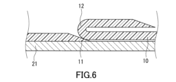
- FIG. 6 is a diagram showing a schematic diagram of still another example of the water stopping method according to the present invention.
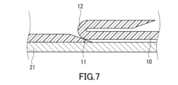
- FIG. 7 is a diagram showing a schematic diagram of still another example of the water stopping method according to the present invention.
- FIG. 8 is a diagram showing a schematic diagram of still another example of the water stopping method according to the present invention.
- the sealing method of the present embodiment includes sealing a space 5 surrounded by a strip-shaped sealant 10 in a watertight manner.
- the sealant 10 is compressed in a direction perpendicular to the main surface F1 of the sealant 10 while overlapping one end 11 and the other end 12 in the length direction of the strip-shaped sealant 10 so that the one end 11 and the other end 12 are aligned in a direction perpendicular to the main surface F1 of the sealant 10.
- the condition of the following formula (1) is satisfied. In the condition of formula (1), as shown in Figs.
- w1 is the width of the sealant 10 after compression at the overlapping portion 15 of the one end 11 and the other end 12 of the sealant
- w0 is the width of the sealant 10 before compression
- t is the thickness of the sealant 10 before compression.
- the sealing material 10 includes an adhesive layer 10p and a foam 10f.
- the adhesive layer 10p forms one of the main surfaces F1.
- the above sealing method can provide a seal structure 1 equipped with a seal material 10.
- a seal structure 1 equipped with a seal material 10.
- one end 11 and the other end 12 of the seal material 10 in the length direction are overlapped so that they are aligned in a direction perpendicular to the main surface F1.
- the seal material 10 is also compressed in a direction perpendicular to the main surface F1, and the space surrounded by the seal material 10 is sealed so as to be waterproof. Furthermore, in the seal structure 1, the condition of the above formula (1) is satisfied.
- the above-described sealing method and sealing structure 1 can use a strip-shaped sealing material 10 to seal the space 5 in a waterproof manner, which tends to reduce material loss compared to, for example, a sealing method that uses an annular sealing material obtained by hollowing out a sheet-shaped sealing material. This tends to increase the yield of products to which this sealing method and sealing structure 1 is applied.
- a sealing method using a strip-shaped sealant 10 may include compressing the sealant 10 with one end 11 and the other end 12 aligned in a direction parallel to the main surface F1. According to this method, a space of about twice the width of the sealant 10 is required in the portion where the one end 11 and the other end 12 are aligned in a direction parallel to the main surface F1. In addition, a gap may occur along the side of the sealant 10 between the one end 11 and the other end 12, making it difficult to achieve high water-stopping properties.
- the location where the sealant is actually placed may be shifted by several millimeters from the location where it should be placed. It is difficult to expect high-precision placement of the sealant as in the case of manual work. Thus, it is difficult to say that the sealing method shown in FIG. 4 is advantageous in terms of space saving and high water-stopping properties.
- the one end 11 and the other end 12 are overlapped so as to be aligned in a direction perpendicular to the main surface F1, so that the space occupied by the sealing material 10 can be easily reduced even in the portion where the one end 11 and the other end 12 are aligned. Furthermore, after extensive research by the inventors, it has been found that high water stoppage is easily achieved by satisfying the condition of the above formula (1). For example, waterproofness that meets IPX7 standards can be achieved.
- a gap G is generated near the portion where the one end 11 and the other end 12 are overlapped.
- the volume of this gap G is considered to be proportional to t* w0 , which is the product of the thickness t and width w0 of the sealing material 10 before compression.
- t* w0 is the product of the thickness t and width w0 of the sealing material 10 before compression.
- the inventors of the present invention have newly discovered that by adjusting the sealing method and sealing structure so that the condition of the above formula (1) is satisfied, the sealing material 10 expands in the length direction as the sealing material 10 is compressed, making it easy to eliminate the gap G, and achieving high water stoppage.
- the condition of the following formula (2) is further satisfied.
- high water stoppage is more likely to be achieved.
- the value of the left side of formula (2) may be 0.06 mm -1 or more, 0.07 mm -1 or more, 0.08 mm -1 or more, 0.09 mm -1 or more, or 0.10 mm -1 or more. (w 1 - w 0 )/(t*w 0 ) ⁇ 0.05mm -1 formula (2)
- a strip-shaped sealing material 10 is arranged in a ring shape on a plate-shaped first member 21 so as to surround the space 5. Then, a plate-shaped second member 22 is arranged to face the first member 21, and the sealing material 10 is pressed by the first member 21 and the second member 22, compressing the sealing material 10. In this way, a sealing structure 1 is obtained in which the space 5 is sealed so as to be waterproof.
- the compression ratio R C of the seal material 10 in the sealing method and seal structure 1 is not limited to a specific value.
- the compression ratio R C is expressed by the following formula (3).
- the compression ratio R C is, for example, 15% or more. In this case, high water stopping properties are more likely to be achieved.
- t is the thickness of the seal material 10 before compression
- t 1 is the thickness of the seal material 10 after compression.
- the compression ratio R may be 18% or more, 20% or more, 25% or more, 30% or more, 32% or more, 35% or more, 40% or more, or 45% or more.
- the compression ratio R is, for example, 90% or less.
- the compression ratio R may be 85% or less, 80% or less, 75% or less, 70% or less, 65% or less, or 60% or less.
- the length L O of the overlapping portion 15 in the longitudinal direction of the seal material 10 is not limited to a specific value.
- the length L O is, for example, 5 mm or more. In this case, high water stoppage is more easily achieved.
- the length L may be 8 mm or more, 10 mm or more, 15 mm or more, 20 mm or more, 25 mm or more, 30 mm or more, 35 mm or more, or 45 mm or more.
- the length L may be, for example, 100 mm or less, 90 mm or less, 80 mm or less, 70 mm or less, or 50 mm or less.
- each of the one end 11 and the other end 12 may have an end surface that extends perpendicular to the main surface F1. This configuration makes it easier to process the sealing material 10 for the sealing method.
- each of the one end 11 and the other end 12 may have an end face that is a slope extending at an angle with respect to the main surface F1 and a plane perpendicular to the main surface F1. In this case, it is possible to prevent the distance between the one end 11 and the other end 12 from suddenly changing in the length direction of the sealing material 10 before the sealing material 10 is compressed.
- the other end 12 may be formed by bending a portion of the sealing material 10 around the other end 12.
- the one end 11 may have an end face that is a slope that extends at an angle with respect to the main surface F1 and a plane perpendicular to the main surface F1. In this case, compression of the sealing material 10 may cause the other end 12 to deform along the slope that is the end face of the one end 11. This makes it easier to achieve high water stoppage.
- At least one selected from the group consisting of a portion including an end of one end 11 in the length direction of the sealing material 10 and a portion including an end of the other end 12 in the length direction of the sealing material 10 may protrude from the overlapping portion 15.
- the overlapping portion 15 may be formed by the one end 11 and the other end 12 crossing each other perpendicularly, or the overlapping portion 15 may be formed by the one end 11 and the other end 12 crossing each other diagonally.
- the sealing material 10 is not limited to a specific sealing material as long as it comprises an adhesive layer 10p and a foam 10f that form the main surface F1, and satisfies the condition of formula (1) in the above sealing method. As shown in FIG. 2, the sealing material 10 may further comprise, for example, an adhesive layer 10q that forms the other main surface F2. The adhesive layer 10q may be omitted from the sealing material 10, and the sealing material 10 may comprise only the foam 10f and the adhesive layer 10p.
- the width w0 of the seal material 10 is not limited to a specific value as long as it satisfies the condition of the above formula (1).
- the width w0 is, for example, 3 to 20 mm, and may be 5 to 15 mm or 5 to 10 mm.
- the larger width is defined as the width w0 .
- the thickness t of the sealing material 10 is not limited to a specific value as long as it satisfies the condition of the above formula (1).
- the thickness t is, for example, 1 to 40 mm, and may be 1 to 30 mm or 3 to 15 mm.
- the structure of the foam 10f is not limited to a specific structure.
- the foam 10f has, for example, a closed-cell structure. In this case, the liquid-tightness inside the foam 10f is high, and the seal structure 1 is more likely to have high water-stopping properties.
- the foam 10f may have, for example, a semi-closed or semi-open cell structure.
- the foam 10f contains open cells before compressive deformation, and when the foam 10f is compressively deformed so as to generate a predetermined compressive strain, the open cells are blocked, causing the structure to change to a structure similar to that of closed cells.
- the foam may have, for example, an open cell structure.
- the material forming the foam 10f is not limited to a specific material.
- the foam 10f may be, for example, a rubber foam or a resin foam. Examples of resin foams are urethane foam, silicone foam, and acrylic foam.
- the foam 10f is preferably a rubber foam.
- the seal structure 1 is more likely to have high water-stopping properties.
- the rubber foam is obtained, for example, by foaming a rubber composition containing rubber, a foaming agent, and a crosslinking agent.
- the rubber may be, for example, an olefin-based elastomer, a styrene-based elastomer, a butyl-based elastomer, a vinyl chloride-based elastomer, or natural rubber.
- olefin-based elastomers are ethylene-propylene rubber (EPM) and ethylene-propylene-diene rubber (EPDM).
- styrene-based elastomers examples include styrene-butadiene rubber (SBR), styrene-butadiene-styrene rubber (SBS), styrene-isoprene-styrene rubber (SIS), styrene-ethylene-butadiene rubber, styrene-ethylene-butylene-styrene rubber (SEBS), styrene-isobutylene-styrene block rubber (SIBS), and styrene-isoprene-propylene-styrene rubber.
- SBR styrene-butadiene rubber
- SBS styrene-butadiene-styrene rubber
- SIS styrene-isoprene-styrene rubber
- SEBS styrene-ethylene-butylene-styrene rubber
- SIBS st
- butyl-based elastomers are butyl rubber, polyisobutylene rubber, polybutene, polyisoprene rubber, and nitrile butadiene rubber (NBR).
- vinyl chloride-based elastomers are chloroprene rubber and chlorosulfonated polyethylene rubber.
- the rubber is preferably an olefin-based elastomer, and more preferably EPDM.
- the seal structure 1 is more likely to have high water-stopping properties.
- EPDM is a rubber obtained by copolymerizing ethylene, propylene, and dienes. By copolymerizing dienes in addition to ethylene and propylene, unsaturated bonds are introduced, making it possible to crosslink with a crosslinking agent.
- dienes are 5-ethylidene-2-norbornene, 1,4-hexadiene, and dicyclopentadiene. These dienes may be used alone or two or more dienes may be used in combination. When the dienes include dicyclopentadiene, the degree of crosslinking can be improved.
- EPDM preferably has long chain branches.
- the method for introducing long branched chains into EPDM is not limited to a specific method, and any known method can be used. If EPDM has long chain branches, the rubber composition can be foamed well.
- the diene content in the EPDM is, for example, 1 mass% or more, preferably 2 mass% or more, and more preferably 3 mass% or more.
- the diene content is, for example, 20 mass% or less, and preferably 15 mass% or less. This makes the rubber foam less susceptible to surface shrinkage and cracks.
- the foaming agent may be an organic foaming agent or an inorganic foaming agent.
- organic blowing agents examples include azo blowing agents, N-nitroso blowing agents, hydrazide blowing agents, semicarbazide blowing agents, fluorinated alkane blowing agents, triazole blowing agents, and other known organic blowing agents.
- azo blowing agents examples include azo blowing agents such as azodicarboxylic acid amide (ADCA), barium azodicarboxylate, azobisisobutyronitrile (AIBN), azocyclohexylnitrile, and azodiaminobenzene.
- N-nitroso blowing agents are N,N'-dinitrosopentamethylenetetramine (DTP), N,N'-dimethyl-N,N'-dinitrosoterephthalamide, and trinitrosotrimethyltriamine.
- DTP N,N'-dinitrosopentamethylenetetramine
- N,N'-dimethyl-N,N'-dinitrosoterephthalamide N,N'-dimethyl-N,N'-dinitrosoterephthalamide
- trinitrosotrimethyltriamine trinitrosotrimethyltriamine
- hydrazide-based blowing agents are 4,4'-oxybis(benzenesulfonylhydrazide) (OBSH), paratoluenesulfonylhydrazide, diphenylsulfone-3,3'-disulfonylhydrazide, 2,4-toluenedisulfonylhydrazide, p,p-bis(benzenesulfonylhydrazide) ether, and benzene-1,3-disulfonylhydrazide, allylbis(sulfonylhydrazide).
- OBSH 4,4'-oxybis(benzenesulfonylhydrazide)
- paratoluenesulfonylhydrazide diphenylsulfone-3,3'-disulfonylhydrazide
- 2,4-toluenedisulfonylhydrazide p,p-bis(benzene
- Examples of semicarbazide-based blowing agents are p-toluylenesulfonylsemicarbazide and 4,4'-oxybis(benzenesulfonylsemicarbazide).
- Examples of fluorinated alkane-based blowing agents are trichloromonofluoromethane and dichloromonofluoromethane.
- An example of a triazole-based blowing agent is 5-morpholyl-1,2,3,4-thiatriazole.
- the organic blowing agent may be thermally expandable fine particles in which a thermally expandable substance is encapsulated in a microcapsule. Examples of such thermally expandable microparticles include commercially available products such as Microspheres (product name, manufactured by Matsumoto Yushi Co., Ltd.).
- Examples of inorganic foaming agents are bicarbonates, carbonates, nitrites, borohydrides, inorganic azides, and other known inorganic foaming agents.
- Examples of bicarbonates are sodium bicarbonate and ammonium bicarbonate.
- Examples of carbonates are sodium carbonate and ammonium carbonate.
- Examples of nitrites are sodium nitrite and ammonium nitrite.
- An example of a borohydride is sodium borohydride.
- the amount of foaming agent is, for example, 0.1 parts by mass or more, preferably 1 part by mass or more, and more preferably 10 parts by mass or more, per 100 parts by mass of rubber.
- the amount of foaming agent is, for example, 50 parts by mass or less, and preferably 30 parts by mass or less.
- crosslinking agents are sulfur compounds such as sulfur (S8) and 4,4'-dithiodimorpholine, selenium, magnesium oxide, lead monoxide, p-quinone dioxime, p,p'-dibenzoylquinone dioxime, quinoid compounds such as poly-p-dinitrosobenzene, polyamines, nitroso compounds such as p-dinitrosobenzene, organic peroxides, resins, and ammonium salts such as ammonium benzoate.
- sulfur compounds such as sulfur (S8) and 4,4'-dithiodimorpholine
- selenium magnesium oxide
- lead monoxide p-quinone dioxime
- p,p'-dibenzoylquinone dioxime quinoid compounds
- quinoid compounds such as poly-p-dinitrosobenzene, polyamines, nitroso compounds such as p-dinitrosobenzene, organic peroxides, resins,
- organic peroxides examples include dicumyl peroxide, dimethyldi(t-butylperoxy)hexane, 1,1-di(t-butylperoxy)cyclohexane, and ⁇ , ⁇ '-di(t-butylperoxy)diisopropylbenzene.
- resins examples include alkylphenol-formaldehyde resins and melamine-formaldehyde condensates. These crosslinking agents may be used alone or in combination of two or more types.
- the cross-linking agent is preferably sulfur (S8) and sulfur compounds, quinoid compounds, or organic peroxides.
- Sulfur (S8) and sulfur compounds are advantageous from the viewpoints of excellent mechanical strength and foaming properties.
- Quinoid compounds are advantageous from the viewpoints of reduced sulfur atom content, reduced corrosiveness, and excellent foaming properties.
- Organic peroxides are advantageous from the viewpoints of improved adhesion to the target object and conformability to steps, etc., in order to realize the seal structure 1.
- the mixing ratio of the crosslinking agent is, for example, 0.05 parts by mass or more, preferably 0.5 parts by mass or more, and more preferably 1 part by mass or more, per 100 parts by mass of rubber.
- the mixing ratio of the crosslinking agent is, for example, 30 parts by mass or less, preferably 20 parts by mass or less, and more preferably 10 parts by mass or less, per 100 parts by mass of rubber.
- a quinoid compound and an organic peroxide may be used in combination as a crosslinking agent. In this case, sufficient crosslinking is likely to occur on the surface of the foam 10f.
- the mixing ratio of the organic peroxide is, for example, 1 part by mass or more, and more preferably 10 parts by mass or more, per 100 parts by mass of the quinoid compound.
- the mixing ratio is, for example, 100 parts by mass or less, and more preferably 50 parts by mass or less, per 100 parts by mass of the quinoid compound.
- the rubber composition preferably contains a foaming aid and a crosslinking aid.
- foaming aids include urea-based foaming aids, salicylic acid-based foaming aids, benzoic acid-based foaming aids, and metal oxides such as zinc oxide. Urea-based foaming aids and metal oxides are preferred. These foaming aids may be used alone or in combination of two or more.
- the mixing ratio of the foaming aid is, for example, 0.5 parts by mass or more, and preferably 1 part by mass or more, per 100 parts by mass of rubber.
- the mixing ratio is, for example, 20 parts by mass or less, and more preferably 10 parts by mass or less, per 100 parts by mass of rubber.
- crosslinking assistants are thiazoles, thioureas, dithiocarbamic acids, guanidines, sulfenamides, thiurams, xanthic acids, aldehyde ammonia, and aldehyde amines.
- thiazoles, thioureas, dithiocarbamic acids, or thiurams are preferably used as crosslinking assistants.
- Examples of thiazoles are dibenzothiazyl disulfide and 2-mercaptobenzothiazole.
- thioureas are diethylthiourea, trimethylthiourea, and dibutylthiourea.
- dithiocarbamic acids are sodium dimethyldithiocarbamate, sodium diethyldithiocarbamate, zinc dimethyldithiocarbamate, zinc diethyldithiocarbamate, and zinc dibenzyldithiocarbamate.
- guanidines are diphenylguanidine and di-o-tolylguanidine.
- sulfenamides are benzothiazyl-2-diethylsulfenamide and N-cyclohexyl-2-benzothiazylsulfenamide.
- Examples of thiurams are tetramethylthiuram monosulfide, tetramethylthiuram disulfide, and tetrabenzylthiuram disulfide.
- Examples of xanthogenates are sodium isopropylxanthate and zinc isopropylxanthate.
- Examples of aldehyde ammonia are acetaldehyde ammonia and hexamethylenetetramine.
- Examples of aldehyde amines are n-butyraldehyde aniline and butyraldehyde monobutylamine.
- the cross-linking aid may be an alcohol.
- alcohols include monohydric alcohols such as ethanol, dihydric alcohols such as ethylene glycol, trihydric alcohols such as glycerin, and polyols (polyoxyethylene glycols) such as polyethylene glycol and polypropylene glycol.
- a polyol is used as the alcohol.
- the number average molecular weight of the polyol is, for example, 200 or more, preferably 300 or more.
- the number average molecular weight of the polyol is, for example, 10,000 or less, preferably 5,000 or less.
- cross-linking aids may be used alone or in combination of two or more types.
- cross-linking agent When sulfur or a sulfur compound is used as the cross-linking agent, it is preferable to use thiazoles, thioureas, dithiocarbamic acids, or thiurams as cross-linking assistants in order to ensure a good foam shape and flexibility of the foam 10f.
- a quinoid compound is used as the cross-linking agent, from the viewpoint of reducing corrosiveness, it is preferable to use an alcohol, and more preferably a polyol, as the cross-linking assistant.
- an alcohol and more preferably a polyol
- polyethylene glycol when a derivative of p-quinone dioxime is used as the quinoid compound, it is advantageous to use polyethylene glycol.
- polyethylene glycol is used as the polyol, the rubber composition can be cross-linked well, and excellent foaming properties are easily ensured.
- the mixing ratio of the cross-linking aid is, for example, 0.01 parts by mass or more, preferably 0.02 parts by mass or more, and more preferably 0.06 parts by mass or more, per 100 parts by mass of rubber.
- the mixing amount is, for example, 20 parts by mass or less, preferably 10 parts by mass or less, and more preferably 5 parts by mass or less, per 100 parts by mass of rubber.
- lubricants examples include stearic acid, its esters, stearin-based compounds such as zinc stearate, and paraffin. These lubricants may be used alone, or two or more types of lubricants may be used in combination.
- the blending ratio of the lubricant is, for example, 0.1 parts by mass or more, and preferably 1 part by mass or more, per 100 parts by mass of rubber.
- the blending ratio is, for example, 20 parts by mass or less, and more preferably 10 parts by mass or less, per 100 parts by mass of rubber.
- An example of a pigment is carbon black.
- a single pigment may be used, or two or more types of pigments may be used in combination.
- the blending ratio of the pigment is, for example, 1 part by mass or more, and preferably 2 parts by mass or more, per 100 parts by mass of rubber.
- the blending ratio is, for example, 50 parts by mass or less, and preferably 30 parts by mass or less, per 100 parts by mass of rubber.
- the filler may be an inorganic filler, an organic filler, or any other known filler.
- inorganic fillers are calcium carbonate, magnesium carbonate, silicic acid and its salts, clay, talc, mica powder, bentonite, silica, alumina, aluminum silicate, and aluminum powder.
- An example of an organic filler is cork. These fillers may be used alone, or two or more types of fillers may be used in combination.
- the compounding ratio of the filler is, for example, 10 parts by mass or more, preferably 30 parts by mass or more, and more preferably 50 parts by mass or more, per 100 parts by mass of rubber.
- the compounding ratio is, for example, 300 parts by mass or less, preferably 200 parts by mass or less, per 100 parts by mass of rubber.
- flame retardants are hydroxides such as calcium hydroxide, magnesium hydroxide, and aluminum hydroxide. These flame retardants may be used alone, or two or more types of flame retardants may be used in combination.
- the blending ratio of the flame retardant is, for example, 5 parts by mass or more, preferably 10 parts by mass or more, and more preferably 15 parts by mass or more, per 100 parts by mass of rubber.
- the blending ratio is, for example, 200 parts by mass or less, preferably 150 parts by mass or less, and more preferably 100 parts by mass or less, per 100 parts by mass of rubber.
- softeners are petroleum oils, asphalts, low molecular weight polymers, organic acid esters, and tackifiers.
- petroleum oils are paraffinic process oils such as paraffin oil, naphthenic process oils, drying oils or animal and vegetable oils, and aromatic process oils.
- An example of drying oils or animal and vegetable oils is linseed oil.
- organic acid esters are phthalates such as di-2-ethylhexyl phthalate (DOP) and dibutyl phthalate (DBP), phosphoric acid esters, higher fatty acid esters, and alkylsulfonic acid esters.
- DOP di-2-ethylhexyl phthalate
- DBP dibutyl phthalate
- phosphoric acid esters higher fatty acid esters
- alkylsulfonic acid esters alkylsulfonic acid esters.
- the softeners may be used alone, or two or more types of softeners may be used in combination.
- the blending ratio of the softener is, for example, 5 parts by mass or more, and preferably 10 parts by mass or more, per 100 parts by mass of rubber.
- the compounding ratio is, for example, 300 parts by mass or less, and more preferably 200 parts by mass or less, per 100 parts by mass of rubber.
- the rubber composition may contain known additives such as plasticizers, antioxidants, antioxidants, colorants, anti-fungal agents, and non-rubber polymers, depending on the purpose and application.
- the adhesive layer 10p and the adhesive layer 10q are not limited to a specific layer as long as they contain an adhesive.
- the adhesive layer 10p and the adhesive layer 10q each contain, for example, a rubber-based polymer.
- the rubber-based polymer is, for example, a synthetic rubber such as a thermoplastic elastomer or a thermosetting elastomer.
- thermoplastic elastomers examples include olefin-based elastomers, styrene-based elastomers, butyl-based elastomers, and vinyl chloride-based elastomers.
- olefin-based elastomers examples include ethylene-propylene rubber (EPM) and ethylene-propylene-diene rubber (EPDM).
- styrene-based elastomers examples include styrene-butadiene rubber (SBR), styrene-butadiene-styrene rubber (SBS), styrene-isoprene-styrene rubber (SIS), styrene-ethylene-butadiene rubber, styrene-ethylene-butylene-styrene rubber (SEBS), styrene-isobutylene-styrene block rubber (SIBS), and styrene-isoprene-propylene-styrene rubber.
- SBR styrene-butadiene rubber
- SBS styrene-butadiene-styrene rubber
- SIS styrene-isoprene-styrene rubber
- SEBS styrene-ethylene-butylene-styrene rubber
- SIBS st
- butyl-based elastomers are butyl rubber, polyisobutylene rubber, polybutene, polyisoprene rubber, and nitrile butadiene rubber (NBR).
- vinyl chloride-based elastomers are chloroprene rubber or chlorosulfonated polyethylene rubber.
- thermosetting elastomers examples include silicone rubber, fluororubber, acrylic rubber, and polyamide rubber.
- the rubber-based polymer is preferably a thermoplastic elastomer, more preferably a styrene-based elastomer or a butyl-based elastomer.
- the content of the filler in each adhesive layer is not limited to a specific value.
- the content of the filler in each adhesive layer is, for example, 5 parts by mass or more, preferably 10 parts by mass or more, and more preferably 20 parts by mass or more, per 100 parts by mass of the rubber-based polymer.
- the content of the filler is, for example, 300 parts by mass or less, preferably 250 parts by mass or less, and more preferably 200 parts by mass or less, per 100 parts by mass of the rubber-based polymer.
- Each of the adhesive layer 10p and the adhesive layer 10q preferably further contains a tackifier. This makes it easier for the principal surface F1 and the principal surface F2 formed by the adhesive layer 10p and the adhesive layer 10q, respectively, to have adhesive strength, for example.
- the amount of tackifier in each of adhesive layer 10p and adhesive layer 10q is not limited to a specific value.
- the amount of tackifier is, for example, 5 parts by mass or more, preferably 10 parts by mass or more, and more preferably 20 parts by mass or more, per 100 parts by mass of rubber-based polymer.
- the amount of tackifier is, for example, 200 parts by mass or less, preferably 100 parts by mass or less, and more preferably 80 parts by mass or less, per 100 parts by mass of rubber-based polymer.
- each of the adhesive layer 10p and the adhesive layer 10q is not limited to a specific value.
- the thickness is, for example, 50 to 400 ⁇ m.
- the thickness of each of the adhesive layer 10p and the adhesive layer 10q may be 70 ⁇ m or more, or 80 ⁇ m or more.
- the thickness of the adhesive layer 10 may be 300 ⁇ m or less, or 250 ⁇ m or less.
- Example 1 SBS resin D1155 manufactured by Kraton and tackifier Alcon M115 manufactured by Arakawa Chemical Industries Co., Ltd. were kneaded at a compounding ratio of 100 parts by mass and 35 parts by mass, respectively, to obtain a mixture. This mixture was hot-pressed under conditions of 150°C and 4 MPa to obtain an adhesive layer according to Example 1 having a thickness of 100 ⁇ m. The styrene content in SBS resin D1155 was 35% by mass. The adhesive layer according to Example 1 was attached to both main surfaces of foam No. 6800 manufactured by Nitto Denko Corporation to obtain a laminate. Foam No. 6800 was an EPDM foam and had a closed cell structure.
- a pressure of 2 kPa was applied to this laminate for 5 minutes in an oven maintained at 140°C to bond the adhesive layer and the foam. Thereafter, the laminate was cut to have a width w 0 of 10 mm to obtain a strip-shaped sealing material according to Example 1.
- the thickness t of the sealing material according to Example 1 was 6 mm, and the length of the sealing material was 350 mm. The end faces at both ends in the length direction of the sealing material according to Example 1 extended perpendicularly to the main surface of the sealing material.
- Two acrylic plates having a thickness of 10 mm were prepared.
- the sealing material according to Example 1 was arranged in a ring shape as shown in FIG. 1.
- the sealing material was overlapped so that one end and the other end in the length direction were aligned in a direction perpendicular to the main surface of the sealing material.
- the dimension L 0 of the overlapping portion of the one end and the other end in the length direction of the sealing material was adjusted to 50 mm.
- the other acrylic plate was arranged so that the two acrylic plates faced each other, and a spacer of a predetermined dimension was placed between the two acrylic plates to adjust the distance between the two acrylic plates.
- the sealing material was compressed at a compression rate of 33%.
- Example 2 The sealing material of Example 2 and the sealing structure of Example 2 using the sealing material of Example 2 were obtained in the same manner as in Example 1, except for the following points.
- the thickness of the foam No. 6800 was adjusted so that the thickness t of the sealing material was 3 mm.
- the compression ratio of the sealing material was adjusted to 35%.
- the width w1 of the sealing member after compression at the overlapping portion was 13.32 mm.
- Example 4 The sealing material according to Example 4 and the sealing structure according to Example 4 using the sealing material according to Example 4 were obtained in the same manner as in Example 1, except for the following points.
- the thickness of the foam No. 6800 was adjusted so that the thickness t of the sealing material was 3 mm.
- the laminate was cut so that the width w 0 of the sealing material was 5 mm.
- the dimension L 0 of the overlapping portion was adjusted to 40 mm.
- the compression rate of the sealing material was adjusted to 50%.
- the width w 1 of the sealing member after compression at the overlapping portion was 7.23 mm.
- Example 5 A sealing material according to Example 5 and a sealing structure according to Example 5 using the sealing material according to Example 5 were obtained in the same manner as in Example 1, except for the following points.
- both end faces in the longitudinal direction of the sealing material were processed to form inclined surfaces extending at an angle with respect to the main surface of the sealing material and a plane perpendicular to the main surface.
- the length of the inclined surface in the longitudinal direction of the sealing material was 15 mm.
- the dimension L O of the overlapping portion was adjusted to 50 mm, and the compression ratio of the sealing material was adjusted to 50%.
- the width w 1 of the sealing member after compression at the overlapping portion was 18.87 mm.
- Example 6 The sealing material according to Example 6 and the sealing structure according to Example 6 using the sealing material according to Example 6 were obtained in the same manner as in Example 1, except for the following points.
- both end faces in the length direction of the sealing material were processed to form inclined surfaces extending at an angle with respect to the main surface of the sealing material and a plane perpendicular to the main surface.
- the length of the inclined surface in the length direction of the sealing material was 15 mm.
- one end face in the length direction of the sealing material was treated as one end as it is, and the part close to the other end face was folded to form the other end.
- the compression ratio of the sealing material was adjusted to 50%.
- the width w 1 of the sealing member after compression at the overlapping portion was 16.84 mm.
- Example 7 The sealing material according to Example 7 and the sealing structure according to Example 7 using the sealing material according to Example 7 were obtained in the same manner as in Example 1, except for the following points.
- both end faces in the length direction of the sealing material were processed to form inclined surfaces extending at an angle with respect to the main surface of the sealing material and a plane perpendicular to the main surface.
- the length of the inclined surface in the length direction of the sealing material was 15 mm.
- one end face in the length direction of the sealing material was treated as one end as it was, and the part close to the other end face was folded to form the other end.
- the compression ratio of the sealing material was adjusted to 50%.
- the width w 1 of the sealing member after compression at the overlapping portion was 17.87 mm.
- Example 10 Except for changing the compression rate of the sealing material to 20%, the seal structure of Example 10 was obtained in the same manner as in Example 8.
- the width w1 of the seal member after compression at the overlapping portion was 12.68 mm.
- a seal structure according to Comparative Example 1 was obtained in the same manner as in Example 1, except for the following points.
- the dimension L O of the overlapping portion was adjusted to 30 mm, and the compression rate of the seal material was adjusted to 33%.
- the width w 1 of the seal material after compression at the overlapping portion was 19.62 mm.
- a seal structure according to Comparative Example 5 was obtained in the same manner as in Example 1, except for the following points.
- the dimension L O of the overlapping portion was adjusted to 40 mm, and the compression rate of the seal material was adjusted to 50%.
- the width w 1 of the seal material after compression at the overlapping portion was 19.89 mm.
- the sealing structures according to each of the examples and comparative examples were submerged in a water tank filled with water up to a height of 1 m, and after 30 minutes had passed, the sealing structures were removed from the water tank and checked for water leakage into the space surrounded by the sealing material to determine whether or not they met the IPX7 standard. If there was no water leakage, it could be evaluated as meeting the IPX7 standard. As a result, the sealing structures according to each of the examples were evaluated as meeting the IPX7 standard. On the other hand, water leakage was confirmed in the sealing structures according to each of the comparative examples, and they were evaluated as not meeting the IPX7 standard.
- the first aspect of the present invention is a band-shaped sealing material having a pressure-sensitive adhesive layer and a foam constituting one of its main surfaces, one end and the other end in a longitudinal direction of the band-shaped sealing material being overlapped so that the one end and the other end are aligned in a direction perpendicular to the main surface, and the band-shaped sealing material is compressed in a direction perpendicular to the main surface to waterproof a space surrounded by the sealing material,
- the condition (w 1 -w 0 )/(t*w 0 ) ⁇ 0.15 mm -1 is satisfied, In the above conditions, w1 is the width of the compressed sealing material at the overlapping portion of the one end and the other end, w0 is the width of the seal before compression, t is the thickness of the seal before compression;
- a sealing method is provided.
- a second aspect of the present invention is The compressibility of the sealing material is 15% or more. According to a first aspect, a sealing method is provided.
- a third aspect of the present invention is The dimension of the overlapping portion in the longitudinal direction of the sealing material is 5 mm or more.
- a sealing method for the first side or the second side is provided.
- a fourth aspect of the present invention is A band-shaped sealing material having a pressure-sensitive adhesive layer and a foam that form one main surface thereof is provided, one end and the other end in a longitudinal direction of the sealing material are overlapped so as to be aligned in a direction perpendicular to the main surface, the sealing material is compressed in a direction perpendicular to the main surface to thereby seal a space surrounded by the sealing material in a waterproof manner;
- the condition (w 1 -w 0 )/(t*w 0 ) ⁇ 0.15 mm -1 is satisfied, In the above conditions, w1 is the width of the compressed sealing material at the overlapping portion of the one end and the other end, w0 is the width of the seal before compression, t is the thickness of the seal before compression; Provide a sealing structure.
- a fifth aspect of the present invention is A band-shaped sealing material, A pressure-sensitive adhesive layer forming one main surface; A foam body, when the sealing material is compressed in a direction perpendicular to the main surface while one end and the other end in the length direction of the sealing material are overlapped so that the one end and the other end are aligned in the direction perpendicular to the main surface, and a space surrounded by the sealing material is sealed in a waterproof manner, it is possible to satisfy the condition ( w1 - w0 )/(t* w0 ) ⁇ 0.15 mm -1 , In the above conditions, w1 is the width of the compressed sealing material at the overlapping portion of the one end and the other end, w0 is the width of the seal before compression, t is the thickness of the seal before compression; A sealant is provided.
Landscapes
- Engineering & Computer Science (AREA)
- General Engineering & Computer Science (AREA)
- Chemical & Material Sciences (AREA)
- Mechanical Engineering (AREA)
- Materials Engineering (AREA)
- Organic Chemistry (AREA)
- Sealing Material Composition (AREA)
Priority Applications (1)
| Application Number | Priority Date | Filing Date | Title |
|---|---|---|---|
| JP2025515155A JPWO2024219238A1 (https=) | 2023-04-17 | 2024-04-03 |
Applications Claiming Priority (2)
| Application Number | Priority Date | Filing Date | Title |
|---|---|---|---|
| JP2023-067413 | 2023-04-17 | ||
| JP2023067413 | 2023-04-17 |
Publications (1)
| Publication Number | Publication Date |
|---|---|
| WO2024219238A1 true WO2024219238A1 (ja) | 2024-10-24 |
Family
ID=93152867
Family Applications (1)
| Application Number | Title | Priority Date | Filing Date |
|---|---|---|---|
| PCT/JP2024/013860 Ceased WO2024219238A1 (ja) | 2023-04-17 | 2024-04-03 | シール方法、シール構造、及びシール材 |
Country Status (2)
| Country | Link |
|---|---|
| JP (1) | JPWO2024219238A1 (https=) |
| WO (1) | WO2024219238A1 (https=) |
Citations (4)
| Publication number | Priority date | Publication date | Assignee | Title |
|---|---|---|---|---|
| JPS5775262U (https=) * | 1980-10-25 | 1982-05-10 | ||
| JPH08198033A (ja) * | 1995-01-30 | 1996-08-06 | Kurihara Sangyo Kk | 自動車部品のシーリング材及びシーリング工法 |
| JP2004245271A (ja) * | 2003-02-12 | 2004-09-02 | Yazaki Corp | 環状シールおよびシール部材 |
| US20230041058A1 (en) * | 2020-01-15 | 2023-02-09 | Tesa Se | Multi-part housing seal, method for the automated application of a multi-part housing seal, and housing comprising a multi-part housing seal |
-
2024
- 2024-04-03 JP JP2025515155A patent/JPWO2024219238A1/ja active Pending
- 2024-04-03 WO PCT/JP2024/013860 patent/WO2024219238A1/ja not_active Ceased
Patent Citations (4)
| Publication number | Priority date | Publication date | Assignee | Title |
|---|---|---|---|---|
| JPS5775262U (https=) * | 1980-10-25 | 1982-05-10 | ||
| JPH08198033A (ja) * | 1995-01-30 | 1996-08-06 | Kurihara Sangyo Kk | 自動車部品のシーリング材及びシーリング工法 |
| JP2004245271A (ja) * | 2003-02-12 | 2004-09-02 | Yazaki Corp | 環状シールおよびシール部材 |
| US20230041058A1 (en) * | 2020-01-15 | 2023-02-09 | Tesa Se | Multi-part housing seal, method for the automated application of a multi-part housing seal, and housing comprising a multi-part housing seal |
Also Published As
| Publication number | Publication date |
|---|---|
| JPWO2024219238A1 (https=) | 2024-10-24 |
Similar Documents
| Publication | Publication Date | Title |
|---|---|---|
| JP4993470B2 (ja) | エチレン・プロピレン・ジエンゴム発泡体 | |
| EP2392609B1 (en) | Water and corrosion resistant EPDM foam and adhesive sealing material | |
| CN101341200B (zh) | 闭孔发泡橡胶片、层压体及使用它们的防水/水密性密封材料 | |
| JP5919140B2 (ja) | エチレン・プロピレン・ジエンゴム発泡体およびシール材 | |
| EP2759565B1 (en) | Ethylene-propylene-diene rubber foam, method for producing same, and sealing material | |
| JP2016141759A (ja) | エチレン・プロピレン・ジエンゴム発泡体およびシール材 | |
| JP2002179825A (ja) | Epdm系発泡体及びその製造方法 | |
| WO2014148297A1 (ja) | 発泡積層体 | |
| JP5963619B2 (ja) | エチレン・プロピレン・ジエンゴム発泡体、その製造方法およびシール材 | |
| WO2014148299A1 (ja) | 発泡積層体 | |
| WO2024143054A1 (ja) | シール材 | |
| WO2024219238A1 (ja) | シール方法、シール構造、及びシール材 | |
| EP2484718B1 (en) | Rubber-based resin closed-cell foam sheet and manufacturing method therefor | |
| WO2014148298A1 (ja) | 発泡積層体 | |
| JP2024095494A (ja) | シール材 | |
| JP5913013B2 (ja) | 遮音材およびシール材 | |
| EP4541865A1 (en) | Seal material | |
| WO2025047833A1 (ja) | 粘着シート、シール材、及びシール構造 | |
| CN103665588A (zh) | 乙烯-丙烯-二烯橡胶发泡体和密封材料 | |
| WO2026042615A1 (ja) | シール材、シール構造、及び粘着シート | |
| JP4509748B2 (ja) | 発泡部材用キャリアテープおよび発泡部材搬送体 | |
| JP2002309026A (ja) | 止水性epdm発泡体 | |
| JP5329690B2 (ja) | エチレン・プロピレン・ジエンゴム発泡体 | |
| JP2002146072A (ja) | ゴム系加硫発泡組成物及びその発泡体 | |
| WO2017002957A1 (ja) | エチレン・プロピレン・ジエンゴム発泡体およびシール材 |
Legal Events
| Date | Code | Title | Description |
|---|---|---|---|
| 121 | Ep: the epo has been informed by wipo that ep was designated in this application |
Ref document number: 24792513 Country of ref document: EP Kind code of ref document: A1 |
|
| ENP | Entry into the national phase |
Ref document number: 2025515155 Country of ref document: JP Kind code of ref document: A |
|
| WWE | Wipo information: entry into national phase |
Ref document number: 2025515155 Country of ref document: JP |
|
| NENP | Non-entry into the national phase |
Ref country code: DE |
|
| 122 | Ep: pct application non-entry in european phase |
Ref document number: 24792513 Country of ref document: EP Kind code of ref document: A1 |