WO2024219081A1 - 水処理方法及び水処理装置 - Google Patents
水処理方法及び水処理装置 Download PDFInfo
- Publication number
- WO2024219081A1 WO2024219081A1 PCT/JP2024/006316 JP2024006316W WO2024219081A1 WO 2024219081 A1 WO2024219081 A1 WO 2024219081A1 JP 2024006316 W JP2024006316 W JP 2024006316W WO 2024219081 A1 WO2024219081 A1 WO 2024219081A1
- Authority
- WO
- WIPO (PCT)
- Prior art keywords
- tank
- water
- biological treatment
- treated
- ammonia
- Prior art date
- Legal status (The legal status is an assumption and is not a legal conclusion. Google has not performed a legal analysis and makes no representation as to the accuracy of the status listed.)
- Ceased
Links
Images








Classifications
-
- C—CHEMISTRY; METALLURGY
- C02—TREATMENT OF WATER, WASTE WATER, SEWAGE, OR SLUDGE
- C02F—TREATMENT OF WATER, WASTE WATER, SEWAGE, OR SLUDGE
- C02F3/00—Biological treatment of water, waste water, or sewage
- C02F3/34—Biological treatment of water, waste water, or sewage characterised by the microorganisms used
Definitions
- This disclosure relates to a water treatment method and a water treatment device for treating water containing dissolved ammonia nitrogen.
- nitrification-denitrification treatment When wastewater containing dissolved ammonia nitrogen flows into public waters, it can cause eutrophication, so ammonia nitrogen is removed by biological treatment.
- nitrification-denitrification treatment nitrifying bacteria oxidize ammonia nitrogen to nitrite nitrogen or nitrate nitrogen under aerobic conditions, and denitrifying bacteria reduce nitrite nitrogen and nitrate nitrogen to nitrogen gas in the presence of a hydrogen donor under anaerobic conditions.
- These two microbial reactions can be expressed by chemical formulas, for example, as follows: Nitrification: NH 3 + 2O 2 ⁇ NO 3 - + 2H + + H 2 O... (Formula 1) Denitrification: NO 3 - + 2H 2 ⁇ 0.5N 2 + 2OH - + H 2 O... (Formula 2)
- Nitrifying bacteria are highly sensitive to environmental changes such as temperature, pH, and ammonia nitrogen concentration, and are easily inhibited by low concentrations of chemical substances.
- nitrifying bacteria are autotrophic bacteria that use ammonia nitrogen or nitrite nitrogen as an energy source and inorganic carbon as a carbon source, their growth rate is slow, and it takes time for their activity to recover once it decreases. In order to stabilize nitrification and protect the quality of the treated water, it is important to detect abnormalities in nitrification and respond early.
- Anomalies in nitrification can be detected, for example, by measuring the flow rate of the water to be treated, the ammonia nitrogen concentration in the water to be treated, and the ammonia nitrogen concentration in the treated water online, and monitoring the inflow ammonia load (kg-N/m 3 /day) and the ammonia removal rate.
- the flow rate of the water to be treated can be easily measured online using a flow sensor.
- the amount of nutrients added, such as phosphorus sources, trace metals, and hydrogen donors, can be optimized, for example, by measuring the flow rate of the water to be treated and the ammonia nitrogen concentration dissolved in the water to be treated online.
- the flow rate of the water to be treated can be easily measured online using a flow sensor.
- indophenol blue absorptiometry, neutralization titration, ion chromatography, and the like have been used as conventional methods for measuring the dissolved ammonia nitrogen concentration. These methods require manual sampling and analysis, and make it impossible to continuously measure the ammonia nitrogen concentration.
- an ammonia sensor using a diaphragm electrode is in practical use. However, since the electrode part is immersed in the solution, dirt adhering to the electrode part must be washed manually periodically.
- the coulometric titration method also allows for online measurement, it is necessary to remove SS components from the treated water by filtration, and the filtration equipment must be replaced manually. In addition, the running cost of the electrolyte used for the measurement is high. Therefore, there is a demand for an online measurement method of dissolved ammonia nitrogen concentration that is easy to maintain and has low running costs.
- Patent Document 1 proposes a method for detecting N2 gas generated in the nitrification/denitrification process as a method for measuring dissolved ammonia nitrogen concentration without contacting the liquid.
- Patent Documents 2, 3, 4, 5, 6, and 7 propose a method for holding collected sample water under alkaline conditions and measuring the generated NH3 gas with an NH3 gas sensor.
- Japanese Patent Application Publication No. 9-43226 Japanese Patent Application Publication No. 55-7667 Japanese Patent Application Publication No. 57-196147 Japanese Unexamined Patent Publication No. 165751/1983 Japanese Unexamined Patent Publication No. 3-61856 Japanese Patent Application Publication No. 8-299988 JP 2022-37285 A
- the object of this disclosure is to provide a water treatment method and water treatment device capable of stably biologically treating water to be treated that contains dissolved ammonia nitrogen, or to provide a water treatment method and water treatment device capable of supplying an appropriate amount of nutrients when biologically treating water to be treated that contains dissolved ammonia nitrogen.
- the water treatment method includes a biological treatment step of biologically treating water to be treated having dissolved ammonia nitrogen in a biological treatment tank; a first measurement step of flowing a portion of the water to be treated flowing into the biological treatment tank as a first sample liquid into a first measurement tank, and under alkaline conditions, transferring the ammonia nitrogen dissolved in the first sample liquid as ammonia gas to the gas phase of the first measurement tank, thereby measuring an ammonia gas concentration C1 ; a second measurement step of flowing a portion of the treated water biologically treated in the biological treatment tank into a second measurement tank as a second sample liquid, and under alkaline conditions, transferring the ammonia nitrogen dissolved in the second sample liquid as ammonia gas to the gas phase of the second measurement tank, thereby measuring an ammonia gas concentration C2; and a control step of controlling the operating conditions of the biological treatment step based on the ammonia gas concentration C1 and the ammonia gas concentration C2 .
- control step controls the operating conditions of the biological treatment step based on an ammonia removal rate calculated by dividing the ammonia nitrogen concentration in the treated water estimated from the ammonia gas concentration C2 by the ammonia nitrogen concentration in the water to be treated estimated from the ammonia gas concentration C1 .
- the water treatment method preferably includes a flow rate measurement step for measuring the flow rate of the water to be treated flowing into the biological treatment tank, and the control step preferably controls the operating conditions of the biological treatment step based on the ammonia removal rate and the inflow ammonia load calculated by multiplying the ammonia nitrogen concentration in the water to be treated by the flow rate of the water to be treated.
- the hydraulic retention time of the first measurement tank and the hydraulic retention time of the second measurement tank are each 1/4 or less of the hydraulic retention time of the biological treatment tank.
- the operating conditions of the biological treatment process include at least one of the flow rate of the water to be treated flowing into the biological treatment tank, the temperature in the biological treatment tank, the pH in the biological treatment tank, the inorganic carbon concentration in the biological treatment tank, and the sludge concentration in the biological treatment tank.
- the water treatment device includes a biological treatment tank for biologically treating water to be treated having dissolved ammonia nitrogen, and a first measurement tank, and a part of the water to be treated flowing into the biological treatment tank is flowed into the first measurement tank as a first sample liquid, and under alkaline conditions, the ammonia nitrogen dissolved in the first sample liquid is transferred as ammonia gas to the gas phase of the first measurement tank, and a first measurement device measures an ammonia gas concentration C1 ; and a second measurement tank is provided, and a part of the treated water biologically treated in the biological treatment tank is flowed into the second measurement tank as a second sample liquid, and under alkaline conditions, the ammonia nitrogen dissolved in the second sample liquid is transferred as ammonia gas to the gas phase of the second measurement tank, and a second measurement device measures an ammonia gas concentration C2 ; and a control device that controls the operating conditions of the biological treatment in the biological treatment tank based on the ammonia gas concentration C1 and the
- control device controls the operating conditions of the biological treatment in the biological treatment tank based on an ammonia removal rate calculated by dividing the ammonia nitrogen concentration in the treatment water estimated from the ammonia gas concentration C2 by the ammonia nitrogen concentration in the water to be treated estimated from the ammonia gas concentration C1.
- the water treatment device has a flow rate measuring means for measuring the flow rate of the water to be treated flowing into the biological treatment tank, and the control device controls the operating conditions of the biological treatment in the biological treatment tank based on the ammonia removal rate and the inflow ammonia load calculated by multiplying the ammonia nitrogen concentration in the water to be treated by the flow rate of the water to be treated.
- the hydraulic retention time of the first measurement tank and the hydraulic retention time of the second measurement tank are each 1/4 or less of the hydraulic retention time of the biological treatment tank.
- the operating conditions of the biological treatment in the biological treatment tank include at least one of the flow rate of the water to be treated flowing into the biological treatment tank, the temperature in the biological treatment tank, the pH in the biological treatment tank, the inorganic carbon concentration in the biological treatment tank, and the sludge concentration in the biological treatment tank.
- the water treatment method is characterized by having a biological treatment process for biologically treating water to be treated having dissolved ammonia nitrogen in a biological treatment tank, a nutrient supply process for supplying a nutrient to the biological treatment tank, a flow rate measurement process for measuring the flow rate of the water to be treated flowing into the biological treatment tank, a measurement process for flowing a portion of the water to be treated flowing into the biological treatment tank as a sample liquid into a measurement tank, and measuring the ammonia gas concentration by transferring the ammonia nitrogen dissolved in the sample liquid as ammonia gas to the gas phase of the measurement tank under alkaline conditions, and a control process for controlling the amount of the nutrient supply based on the ammonia nitrogen concentration in the water to be treated estimated from the ammonia gas concentration and the flow rate of the water to be treated.
- the hydraulic retention time of the measurement tank is 1/4 or less of the hydraulic retention time of the biological treatment tank.
- the nutrient contains at least one of a phosphorus source, a trace metal, and a hydrogen donor.
- the water treatment method includes an acid supply step of supplying an acid to the measurement tank to clean the inside of the measurement tank.
- the water treatment device includes a biological treatment tank for biologically treating water to be treated having dissolved ammonia nitrogen, a nutrient supplying device for supplying nutrients to the biological treatment tank, and a measuring tank, which is configured to flow a portion of the water to be treated flowing into the biological treatment tank as a sample liquid into the measuring tank, and measure the ammonia gas concentration by transferring the ammonia nitrogen dissolved in the sample liquid as ammonia gas to the gas phase of the measuring tank under alkaline conditions, and a control device for controlling the amount of the nutrient supply based on the ammonia nitrogen concentration in the water to be treated estimated from the ammonia gas concentration and the flow rate of the water to be treated.
- the hydraulic retention time of the measurement tank is 1/4 or less of the hydraulic retention time of the biological treatment tank.
- the nutrients contain at least one of a phosphorus source, a trace metal, and a hydrogen donor.
- the water treatment device preferably also includes an acid supply device that supplies an acid to the measurement tank to clean the inside of the measurement tank.
- a water treatment method and a water treatment device capable of stably biologically treating water to be treated that contains dissolved ammonia nitrogen, or to provide a water treatment method and a water treatment device capable of supplying an appropriate amount of nutrients when biologically treating water to be treated that contains dissolved ammonia nitrogen.
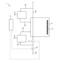
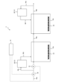
- FIG. 1 is a schematic configuration diagram illustrating an example of a water treatment device according to an embodiment of the present invention.
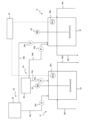
- FIG. 2 is a schematic configuration diagram showing an example of a first measurement device and a second measurement device.
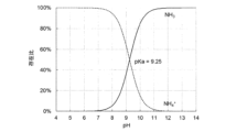
- FIG. 11 is a schematic configuration diagram showing another example of the first measurement device and the second measurement device. The abundance ratio of NH3 and NH4 + at each pH is shown.
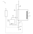
- FIG. 4 is a schematic configuration diagram showing another example of the water treatment device according to the present embodiment.
- FIG. 4 is a schematic configuration diagram showing another example of the water treatment device according to the present embodiment.
- FIG. 2 is a graph showing the relationship between the ammonia nitrogen concentration in the simulated wastewater and the ammonia gas concentration in the gas phase in Experimental Example 1.
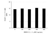
- FIG. 1 is a graph showing the ammonia gas concentration in the gas phase versus the calcium concentration (0 to 400 mg-Ca/L) in the simulated wastewater of Experimental Example 2.
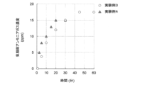
- FIG. 13 is a graph showing the change over time in ammonia gas concentration in the gas phase in Experimental Examples 3 and 4.
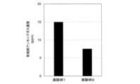
- FIG. 13 shows the measurement results of ammonia gas concentration in the gas phase of a covered measurement tank in Experimental Example 1, and the measurement results of ammonia gas concentration in the gas phase of an uncovered measurement tank in Experimental Example 9.
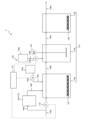
- 1 is a schematic configuration diagram illustrating an example of a water treatment device according to an embodiment of the present invention.
- FIG. 2 is a schematic diagram illustrating an example of a measuring device.
- FIG. 11 is a schematic configuration diagram showing another example of the first measurement device and the second measurement device.
- FIG. 13 is a graph showing the relationship between the ammonia nitrogen concentration in the simulated wastewater and the ammonia gas concentration in the gas phase in Experimental Example 11.
- FIG. 13 is a graph showing the ammonia gas concentration in the gas phase versus the calcium concentration (0 to 400 mg-Ca/L) in the simulated wastewater of Experimental Example 12.
- FIG. 13 is a graph showing the change over time in ammonia gas concentration in the gas phase in Experimental Examples 13 and 14.
- FIG. 13 shows the measurement results of ammonia gas concentration in the gas phase of a covered measurement tank in Experimental Example 11, and the measurement results of ammonia gas concentration in the gas phase of an uncovered measurement tank in Experimental Example 17.
- FIG. 1 is a schematic diagram showing an example of a water treatment device according to this embodiment.
- the water treatment device 1 shown in FIG. 1 has a biological treatment tank 10, a first measuring device 12, a second measuring device 14, a control device 16, a flowmeter 18, and a treated water supply pump 20.
- An aeration device 22 is installed at the bottom of the biological treatment tank 10. Note that with regard to the first measuring device 12 and the second measuring device 14 shown in FIG. 1, only the first measuring tank 24 and the second measuring tank 32 are drawn, and the other components are omitted.
- FIG. 2 is a schematic diagram showing an example of the first measuring device and the second measuring device.
- the first measuring device 12 has a first measuring tank 24, a pH meter 26a, an ammonia gas concentration meter 28a, and an agitator 30.
- the ammonia gas concentration meter 28a is installed in the gas phase of the first measuring tank 24.
- the second measuring device 14 has a second measuring tank 32, a pH meter 26b, an ammonia gas concentration meter 28b, and an agitator 30.
- the ammonia gas concentration meter 28b is installed in the gas phase of the second measuring tank 32.
- the ammonia gas concentration meters 28a and 28b may be installed in piping connected to the gas phase of the first measuring tank 24 or the gas phase of the second measuring tank 32.
- the first measuring device 12 and the second measuring device 14 also have a pH adjuster supply device.
- the pH adjuster supply device has, for example, an alkaline agent supply device 39 including an alkaline agent storage tank 34, alkaline agent supply pumps 36a, 36b, and alkaline agent supply pipes 38a, 38b, and an acid agent supply device 45 including an acid agent storage tank 40, acid agent supply pumps 42a, 42b, and acid agent supply pipes 44a, 44b.
- the pH meter 26a and the alkaline agent supply pump 36a, and the pH meter 26b and the alkaline agent supply pump 36b are electrically connected by wire or wirelessly.
- the alkaline agent supply pumps 36a, 36b for example, read the pH values of the pH meters 26a, 26b, and operate so that the first measuring tank 24 and the second measuring tank 32 are kept under alkaline conditions.
- one pH adjuster supply device is used for both the first measurement device 12 and the second measurement device 14, but one pH adjuster supply device may be provided for each of the first measurement device 12 and the second measurement device 14.
- a pipe 46a is connected to the biological treatment tank 10.
- a flow meter 18 and a treated water supply pump 20 are installed in the pipe 46a.
- a pipe 46b is also connected to the biological treatment tank 10.
- One end of a pipe 46c is connected to the pipe 46a, and the other end of the pipe 46c is connected to the first measuring tank 24.
- One end of a pipe 46d is connected to the first measuring tank 24, and the other end of the pipe 46d is connected to the biological treatment tank 10.
- One end of a pipe 46e is connected to the pipe 46b, and the other end of the pipe 46e is connected to the second measuring tank 32.
- One end of a pipe 46f is connected to the second measuring tank 32, and the other end of the pipe 46f is connected to the biological treatment tank 10.
- an alkaline agent supply pipe 38a is connected to the alkaline agent storage tank 34, and the other end of the alkaline agent supply pipe 38a is connected to the first measuring tank 24.
- one end of the alkaline agent supply pipe 38b is connected to the alkaline agent storage tank 34, and the other end of the alkaline agent supply pipe 38b is connected to the second measurement tank 32.
- An alkaline agent supply pump 36a is installed in the alkaline agent supply pipe 38a, and an alkaline agent supply pump 36b is installed in the alkaline agent supply pipe 38b.
- One end of the acid agent supply pipe 44a is connected to the acid agent storage tank 40, and the other end of the acid agent supply pipe 44a is connected to the first measurement tank 24.
- one end of the acid agent supply pipe 44b is connected to the acid agent storage tank 40, and the other end of the acid agent supply pipe 44b is connected to the second measurement tank 32.
- An acid agent supply pump 42a is installed in the acid agent supply pipe 44a, and an acid agent supply pump 42b is installed in the acid agent supply pipe 44b.
- the control device 16 is connected to the ammonia gas concentration meters 28a, 28b, the flow meter 18, and the treated water supply pump 20 by wired or wireless electrical connections.
- the control device 16 is composed of, for example, a microcomputer and electronic circuits, which are made up of a CPU that calculates programs, and a ROM and RAM that store the programs and calculation results, and reads out a predetermined program stored in the ROM or the like, and executes the program to control the operation of the water treatment device 1. Details will be described later, but for example, the control device 16 controls the operation of the treated water supply pump 20 based on the ammonia gas concentration measured by the ammonia gas concentration meters 28a, 28b.
- the treated water supply pump 20 is operated to allow the treated water, in which ammonia nitrogen is dissolved, to flow from the pipe 46a into the biological treatment tank 10.
- an oxygen-containing gas such as air is supplied by the aeration device 22, and the treated water is mixed with sludge containing microorganisms.
- the ammonia nitrogen in the treated water is biologically treated (e.g., nitrification treatment) by microorganisms under aerobic conditions.
- the biological treatment process in the biological treatment tank 10 is not limited to nitrification treatment only, and may be any biological treatment including nitrification treatment.
- the treated water that has been biologically treated in the biological treatment tank 10 is discharged from the pipe 46b.
- a portion of the water to be treated passing through the pipe 46a flows into the first measurement tank 24 from the pipe 46c as the first sample liquid
- a portion of the water to be treated passing through the pipe 46b flows into the second measurement tank 32 from the pipe 46e as the second sample liquid.
- the pH of the first sample liquid and the second sample liquid are measured at any time by the pH meters 26a and 26b, and the alkaline agent supply pumps 36a and 36b are operated based on the measured pH value.
- a predetermined amount of alkaline agent is supplied from the alkaline agent storage tank 34 to the first measurement tank 24 and the second measurement tank 32, and the inside of each of the first measurement tank 24 and the second measurement tank 32 is maintained under alkaline conditions.
- the first sample liquid and the alkaline agent are stirred by the agitator 30, and in the second measurement tank 32, the second sample liquid and the alkaline agent are stirred by the agitator 30.
- first measurement tank 24 alkaline conditions are established, ammonia nitrogen dissolved in the first sample liquid is transferred to the gas phase as ammonia gas (NH 3 ), and the ammonia gas concentration C 1 is measured by the ammonia gas concentration meter 28 a (first measurement step).
- second measurement tank 32 alkaline conditions are established, and a part of the ammonia nitrogen dissolved in the second sample liquid is transferred to the gas phase as ammonia gas (NH 3 ), and the ammonia gas concentration C 2 is measured by the ammonia gas concentration meter 28 b (second measurement step).
- Fig. 3 is a schematic diagram showing another example of the first measuring device and the second measuring device.
- the first measuring device 12 and the second measuring device 14 shown in Fig. 3 are not equipped with a pH meter.
- an alkaline agent is added at a constant ratio to the inflow water amount, and the inside of the tank is made alkaline, and the ammonia gas concentration C1 and the ammonia gas concentration C2 are measured.
- ammonia nitrogen exists as NH3 and NH4 + , and the equilibrium relationship is expressed by the following formula.
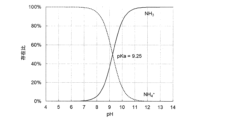
- Figure 4 shows the abundance ratio of NH3 and NH4 + at each pH.
- the acid dissociation constant (pKa) of NH4 + is 9.25, and the abundance ratio of NH3 in the dissolved ammonia nitrogen is 8% at pH 8, 36% at pH 9, 85% at pH 10, and 98% at pH 11.
- a part of the dissolved NH3 volatilizes as ammonia gas ( NH3 gas).
- the abundance ratio of NH3 is high, the amount of NH3 volatilized as ammonia gas also increases.
- the inside of the measurement tank only needs to be alkaline, but even if the concentration of dissolved ammonia nitrogen is low, it is preferable to set the pH in the measurement tank to 10 or more, and more preferably to 11 or more, in that ammonia gas can be easily measured by an ammonia gas concentration meter.
- the control device 16 controls the operation of the biological treatment in the biological treatment tank 10 based on the ammonia gas concentrations C 1 and C 2 (control process).
- the ammonia gas concentrations C 1 and C 2 measured by the ammonia gas concentration meters 28a and 28b for example, if the ammonia gas concentration C 2 is smaller than the ammonia gas concentration C 1 , it can be said that the ammonia nitrogen in the treated water is sufficiently removed, so it is presumed that the biological treatment is performed normally, but if there is almost no difference between the two, it is presumed that the biological treatment is not progressing and is abnormal.
- the control device 16 presumes that the biological treatment is abnormal, so it reduces the output of the treated water supply pump 20 and reduces the flow rate of the treated water supplied to the biological treatment tank 10. This reduces the inflow ammonia load of the biological treatment tank 10, making it possible to increase the treatment capacity of ammonia nitrogen.
- control device 16 presumes that the biological treatment is proceeding normally, and increases the output of the water supply pump 20 to restore the flow rate of the water to be treated.
- control of the flow rate of the water to be treated is not limited to controlling the water supply pump 20, and may be adjusted, for example, by adjusting the opening/closing degree of a valve installed in the pipe 46a.
- control items of the operating conditions of the biological treatment reaction are not limited to the flow rate of the water to be treated flowing into the biological treatment tank 10, and include, for example, the temperature in the biological treatment tank 10, the pH in the biological treatment tank 10, the inorganic carbon concentration in the biological treatment tank 10, and the sludge concentration in the biological treatment tank 10.
- the control device 16 may operate a device (not shown) that supplies steam into the biological treatment tank 10 to supply steam into the biological treatment tank 10, thereby increasing the temperature in the biological treatment tank 10 and increasing the treatment capacity of ammonia nitrogen.
- the control device 16 may operate a device (not shown) that supplies a pH adjuster into the biological treatment tank 10 to adjust the pH in the biological treatment tank 10 (for example, pH 7.5 to 8.0), increase the inorganic carbon concentration in the tank, and increase the treatment capacity of ammonia nitrogen.
- the control device 16 may operate a device (not shown) that supplies bicarbonate or carbonate to the biological treatment tank 10 to increase the inorganic carbon concentration in the biological treatment tank 10 and increase the treatment capacity of ammonia nitrogen.
- control device 16 may operate a device (not shown) that supplies biological sludge to the biological treatment tank 10 to increase the amount of biological sludge in the biological treatment tank 10 and increase the treatment capacity of ammonia nitrogen.
- the operating conditions of the biological treatment are returned to the original state. Note that the above-mentioned control of the operating conditions is one example, and the operating conditions may be controlled according to, for example, the difference or increase/decrease between the ammonia gas concentrations C1 and C2 or the ratio.
- the control device 16 may control the operating conditions of the biological treatment based on the ammonia removal rate obtained by dividing the ammonia nitrogen concentration D2 in the treated water estimated from the ammonia gas concentration C2 by the ammonia nitrogen concentration D1 in the water to be treated estimated from the ammonia gas concentration C1.
- Correlation information between the dissolved ammonia nitrogen concentration and the ammonia gas concentration is stored in advance in the control device 16. Then, the control device 16 uses the correlation information to obtain the dissolved ammonia nitrogen concentration from the ammonia gas concentration C1 detected by the ammonia gas concentration meter 28a (this is set as the ammonia nitrogen concentration D1 in the water to be treated).
- the control device 16 also uses the correlation information to obtain the dissolved ammonia nitrogen concentration from the ammonia gas concentration C2 detected by the ammonia gas concentration meter 28b (this is set as the ammonia nitrogen concentration D2 in the water to be treated).
- the control device 16 divides the ammonia nitrogen concentration D2 in the treated water by the ammonia nitrogen concentration D1 in the water to be treated ( D2 / D1 ) to obtain the ammonia removal rate (1- D2 / D1 ).
- the control device 16 controls the operating conditions of the biological treatment in the same manner as in the case where the biological treatment is estimated to be abnormal, as described above.
- control device 16 returns the operating conditions of the biological treatment to their original state.
- the control device 16 may control the operating conditions of the biological treatment in accordance with the increase or decrease in the ammonia removal rate.
- the control device 16 may control the operating conditions of the biological treatment based on the inflow ammonia load calculated by multiplying the ammonia removal rate and the ammonia nitrogen concentration D1 in the water to be treated by the flow rate of the water to be treated flowing into the biological treatment tank 10.
- the control device 16 calculates the ammonia removal rate from the ammonia nitrogen concentration D1 in the water to be treated and the ammonia nitrogen concentration D2 in the treated water.
- the control device 16 also calculates the inflow ammonia load by multiplying the flow rate of the water to be treated detected by the flow meter 18 by the ammonia nitrogen concentration D1 in the water to be treated.
- the control device 16 controls the operating conditions of the biological treatment in the same manner as, for example, when the biological treatment is estimated to be abnormal as described above. After that, when the ammonia removal rate and the inflow ammonia load are within the range of the preset planned values, the control device 16 returns the operating conditions of the biological treatment reaction to the original state.
- the control device 16 may control the operating conditions of the biological treatment in accordance with an increase or decrease in the ammonia removal rate and an increase or decrease in the inflow ammonia load.
- the planned value of the ammonia removal rate is, for example, preferably in the range of 90% to 100%, and more preferably in the range of 95% to 100%.
- the planned value of the influent ammonia load is, for example, preferably in the range of 0.1 to 0.3 kg-N/ m3 /day in the activated sludge process, and preferably in the range of 0.5 to 1.0 kg-N/ m3 /day in the biofilm process (e.g., fixed bed type or fluidized bed type) or granule process.
- the biological treatment tank 10, the first measuring device 12, and the second measuring device 14 are described in detail below. Note that, hereinafter, when referring to a measuring device, it refers to at least one of the first measuring device 12 and the second measuring device 14, and when referring to a measuring tank, it refers to at least one of the first measuring tank 24 and the second measuring tank 32.
- the biological treatment tank 10 may be of any type as long as it can biologically treat the water to be treated in which ammonia nitrogen is dissolved.
- Examples include biological treatment tanks that biologically treat the water to be treated in which ammonia nitrogen is dissolved by the activated sludge method, the membrane bioreactor (MBR) method, the fixed bed or fluidized bed biofilm method, or the granule method.
- Examples of biological treatment methods for the water to be treated in which ammonia nitrogen is dissolved include the nitrification method, the nitrification-denitrification method, the circulating nitrification-denitrification method, and the anaerobic ammonia oxidation method (e.g., the anammox method).
- the biological treatment tank 10 is not limited to a single tank, and may be composed of multiple tanks, as described below.
- the measurement tank constituting the measurement device is preferably covered. By covering the measurement tank, dilution of the ammonia gas concentration due to air mixing is suppressed, and the ammonia gas detection sensitivity of the ammonia gas concentration meter can be increased.
- the pipe 46d connected to the first measurement tank 24 and the pipe 46f connected to the second measurement tank 32 are water-sealed.
- the pipes 46d and 46f can be water-sealed by providing a water tank for storing water in the pipes 46d and 46f, extending the pipes 46d and 46f below the water surface of the biological treatment tank 10, or making the pipes 46d and 46f S-shaped.
- the inflow of the first sample liquid into the first measurement tank 24 and the inflow of the second sample liquid into the second measurement tank 32 may each be continuous or intermittent.
- the hydraulic retention time of the first measuring tank 24 and the hydraulic retention time of the second measuring tank 32 are each preferably 1/4 or less of the hydraulic retention time of the biological treatment tank 10. By making the hydraulic retention time of the measuring tanks 1/4 or less of the hydraulic retention time of the biological treatment tank 10, for example, abnormalities in biological treatment in the biological treatment tank 10 can be detected more quickly.
- a mist separator may be installed in front of the ammonia gas concentration meters 28a and 28b.
- the ammonia gas concentration meters 28a and 28b include electrochemical, semiconductor, or catalytic combustion ammonia gas concentration meters.
- the ammonia gas concentration may be measured online or manually.
- alkali is consumed, for example, as shown in the above formula 1. Therefore, by returning the first sample liquid discharged from the first measuring tank 24 and the second sample liquid discharged from the second measuring tank 32 to the biological treatment tank 10 through the pipes 46d and 46f, alkali can be replenished to the biological treatment tank 10.
- alkaline agents supplied to the measuring tanks for ammonia gas measurement include sodium hydroxide, potassium hydroxide, calcium hydroxide, etc.
- the acid supply pumps 42a, 42b are operated periodically (e.g., once a day) to supply a predetermined amount of acid from the acid storage tank 40 to the first measuring tank 24 and the second measuring tank 32, thereby removing scale and cleaning the inside of the tank.
- the wastewater is preferably supplied to, for example, a denitrification tank.
- alkali is produced as shown in the above formula 2, so by supplying the wastewater after cleaning the scale in the measurement tank to the denitrification tank, acid can be replenished to the denitrification tank.
- acids that can be supplied to the measurement tank to clean the inside of the tank include hydrochloric acid, sulfuric acid, nitric acid, phosphoric acid, citric acid, oxalic acid, lactic acid, ascorbic acid, and malic acid. Of these, hydrochloric acid or nitric acid, which can lower the pH by adding a small amount, are preferred.
- FIG. 5 is a schematic diagram showing another example of a water treatment device according to this embodiment.
- the water treatment device 2 shown in FIG. 5 includes a single measurement device 50 that serves both the first and second measurement devices described above.
- the single measurement device 50 has a single measurement tank 52 that serves both the first and second measurement tanks. Note that FIG.
- the single measurement device 5 only illustrates the single measurement tank 52 that constitutes the single measurement device 50, and the other components are not illustrated, but like the first and second measurement devices described above, the single measurement device includes, for example, a pH meter, an ammonia gas concentration meter, an agitator, an alkaline agent supply device, an acid agent supply device, etc.
- one end of pipe 46k is connected to pipe 46a, and the other end of pipe 46k is connected to single measurement tank 52.
- One end of pipe 46m is connected to pipe 46b, and the other end of pipe 46m is connected to single measurement tank 52.
- One end of pipe 46n is connected to single measurement tank 52, and the other end of pipe 46n is connected to biological treatment tank 10.
- the ammonia gas concentration is measured as follows. First, a part of the water to be treated passing through the pipe 46a flows into the single measurement tank 52 from the pipe 46k as the first sample liquid. Then, the pH of the first sample liquid is measured at any time by the pH meter, and a predetermined amount of alkaline agent is supplied from the alkaline agent supply device to the single measurement tank 52 based on the measured pH value, and the inside of the tank is kept under alkaline conditions.
- the single measurement tank 52 alkaline conditions are created, and a part of the ammonia nitrogen dissolved in the first sample liquid is transferred to the gas phase as ammonia gas, and the ammonia gas concentration C1 is measured by the ammonia gas concentration meter. After a predetermined time has elapsed, the supply of the first sample liquid to the single measurement tank 52 is stopped, and the measurement of the ammonia gas concentration C1 is terminated. Next, a part of the treated water passing through the pipe 46b flows into the single measurement tank 52 from the pipe 46m as the second sample liquid, and the first sample liquid in the single measurement tank 52 is replaced with the second sample liquid.
- the tank is made alkaline in the same manner as described above, a part of the ammonia nitrogen dissolved in the second sample liquid is transferred to the gas phase as ammonia gas, and the ammonia gas concentration C2 is measured by the ammonia gas concentration meter.
- the measurements of the ammonia gas concentrations C1 and C2 are repeatedly performed at predetermined time intervals in the single measurement tank 52.
- FIG. 6 is a schematic diagram showing another example of the water treatment device according to the present embodiment.
- the water treatment device 3 shown in FIG. 6 has a plurality of biological treatment tanks. As shown in FIG. 6, the biological treatment tank 10a and the biological treatment tank 10b are connected by a pipe 46p.
- a part of the water to be treated flowing into the biological treatment tank 10a at the front stage is made to flow into the first measurement tank 24 as the first sample liquid, and the ammonia gas concentration C 1 is measured.
- a part of the treated water discharged from the biological treatment tank 10b at the rear stage is made to flow into the second measurement tank 32 as the second sample liquid, and the ammonia gas concentration C 2 is measured.
- Example 1 A simulated wastewater containing ammonia nitrogen (1-50 mg-N/L), calcium (400 mg-Ca/L), inorganic carbon (20 mg-C/L), phosphorus (1 mg-P/L) and trace metals was introduced into a covered measuring tank with a liquid phase volume of 1 L and a gas phase volume of 0.4 L so that the hydraulic retention time (HRT) was 10 minutes. Then, 25% sodium hydroxide was added to the measuring tank so that the pH in the measuring tank was 11 or more, and the mixture was thoroughly mixed by stirring. The water temperature was 20-23°C, and the ammonia gas concentration transferred to the gas phase of the measuring tank was measured with an ammonia gas sensor 30 minutes after the simulated wastewater was introduced under atmospheric pressure. The ammonia nitrogen concentration in the simulated wastewater was measured by indophenol blue absorptiometry.
- Example 2 A simulated wastewater containing an ammonia nitrogen concentration of 20 mg-N/L and a calcium concentration of 0 to 400 mg-Ca/L was allowed to flow into the measurement tank. The other conditions were the same as those in Experimental Example 1.
- Figure 8 shows the ammonia gas concentration in the gas phase versus the calcium concentration (0 to 400 mg-Ca/L) in the simulated wastewater in Experimental Example 2. As shown in Figure 8, even if the calcium concentration in the simulated wastewater changes, there is almost no effect on the ammonia concentration in the gas phase. In this way, since the ammonia gas concentration in the gas phase is independent of the calcium concentration in the simulated wastewater, it is not necessary to carry out pretreatment to remove calcium from the wastewater when measuring the ammonia gas concentration.
- Example 3 A simulated wastewater containing an ammonia nitrogen concentration of 20 mg-N/L was allowed to flow into the measurement tank so that the HRT was 10 minutes. The ammonia gas concentration in the gas phase was measured 0, 5, 10, 15, 30, 45, and 60 minutes after the start of the flow. The other conditions were the same as in Experimental Example 1.
- Example 4 A simulated wastewater containing an ammonia nitrogen concentration of 20 mg-N/L was allowed to flow into the measurement tank so that the HRT was 5 minutes. The ammonia gas concentration in the gas phase was measured 0, 2.5, 5, 10, 15, 20, and 30 minutes after the start of the flow. The other conditions were the same as in Experimental Example 1.
- FIG. 9 shows the change in ammonia gas concentration in the gas phase over time in Experimental Examples 3 and 4. As shown in FIG. 9, it takes four times the HRT of the measurement tank for the ammonia gas concentration in the gas phase to reach its maximum value. Since it is preferable for the NH3 gas concentration to reach its maximum value at least once within one HRT of the biological treatment tank, it is preferable to set the HRT of the measurement tank to 1/4 or less of the HRT of the biological treatment tank.
- the HRT of the measurement tank can be increased or decreased by controlling the inflow of simulated wastewater into the measurement tank. If the measurement tank is sufficiently smaller than the biological treatment tank, the inflow of simulated wastewater may be small, and the pump that supplies the simulated wastewater to the measurement tank can be made smaller.
- Example 5 Wastewater from a semiconductor factory containing ammonia nitrogen was allowed to flow into the measurement tank. Other conditions were the same as in Experimental Example 1. A correlation was confirmed using this wastewater as in Experimental Example 1 based on the actual measured value of the ammonia nitrogen concentration in the wastewater from a semiconductor factory, measured by indophenol blue absorptiometry, and the measured value of the ammonia gas concentration in the gas phase, and the error rate of the value of the ammonia nitrogen concentration calculated using the obtained approximation formula was 13%. From this result, it is possible to use the ammonia gas concentration in the gas phase, measured without filtering the wastewater, for calculating the ammonia nitrogen concentration in the wastewater from a semiconductor factory.
- Example 6 The simulated wastewater used in Experimental Example 1 was supplied to a nitrification tank filled with a sponge-like carrier to carry out biological treatment. The treated water discharged from the nitrification tank was then allowed to flow into a measurement tank. The other conditions were the same as those in Experimental Example 1.
- the amount of suspended solids (SS) in the treated water was 18 mg/L, and the ammonia nitrogen concentration measured using indophenol blue spectrophotometry was 17.9 mg-N/L.
- the ammonia gas concentration in the gas phase of the measurement tank was 14.5 ppm, so the ammonia nitrogen concentration in the wastewater was calculated to be 18.2 mg-N/L using the approximation formula obtained in Experimental Example 1.
- the error rate between the actual value obtained using indophenol blue spectrophotometry and the value calculated from the ammonia gas concentration in the gas phase was 1.6%.
- Example 7 The simulated wastewater used in Experimental Example 1 was supplied to a nitrification tank where biological treatment was performed by a semi-batch activated sludge nitrogen removal method, and biological treatment was performed. The treated water discharged from the nitrification tank was then allowed to flow into a measurement tank. The other conditions were the same as those in Experimental Example 1.
- the SS in the treated water was 1700 mg/L, and the ammonia nitrogen concentration measured by indophenol blue absorptiometry was 12.9 mg-N/L. Because the ammonia gas concentration in the gas phase of the measurement tank was 9.5 ppm, the ammonia nitrogen concentration in the wastewater was calculated to be 11.9 mg-N/L using the approximate formula obtained in Experimental Example 1. The error rate between the actual value obtained by indophenol blue absorptiometry and the value calculated from the ammonia gas concentration in the gas phase was 7.6%. From these results, it can be said that the ammonia gas concentration in the gas phase measured without filtration can be used to calculate the ammonia nitrogen concentration in the treated water.
- Example 8 20% hydrochloric acid was added to the measurement tank used in Experimental Example 1, the pH in the tank was adjusted to 2 or less, and the tank was stirred for 5 minutes. As a result, the scale precipitated in the tank under alkaline conditions was dissolved.
- Example 9 A simulated wastewater containing an ammonia nitrogen concentration of 20 mg-N/L was allowed to flow into an uncovered measurement tank. The other conditions were the same as those in Example 1.
- Figure 10 shows the measurement results of the ammonia gas concentration in the gas phase of the covered measurement tank in Experimental Example 1, and the measurement results of the ammonia gas concentration in the gas phase of the uncovered measurement tank in Experimental Example 9. As shown in Figure 10, dilution of ammonia gas is suppressed when the ammonia gas concentration in the gas phase is measured using a covered measurement tank.
- a biological treatment step of biologically treating the water to be treated in which ammonia nitrogen is dissolved in the biological treatment tank A first measurement step of flowing a part of the water to be treated flowing into the biological treatment tank into a first measurement tank as a first sample liquid, transferring ammonia nitrogen dissolved in the first sample liquid to a gas phase portion of the first measurement tank as ammonia gas under alkaline conditions, and measuring an ammonia gas concentration C1 ; A second measurement step of flowing a part of the treated water biologically treated in the biological treatment tank into a second measurement tank as a second sample liquid, and transferring ammonia nitrogen dissolved in the second sample liquid to a gas phase portion of the second measurement tank as ammonia gas under alkaline conditions to measure an ammonia gas concentration C2 ; and a control step of controlling operating conditions of the biological treatment step based on the ammonia gas concentrations C1 and C2 .
- a biological treatment tank for biologically treating the water to be treated in which ammonia nitrogen is dissolved a first measuring device that has a first measurement tank, flows a part of the water to be treated flowing into the biological treatment tank as a first sample liquid into the first measurement tank, and transfers ammonia nitrogen dissolved in the first sample liquid to a gas phase portion of the first measurement tank as ammonia gas under alkaline conditions to measure an ammonia gas concentration C1 ;
- a second measurement device has a second measurement tank, and a part of the treated water biologically treated in the biological treatment tank is introduced into the second measurement tank as a second sample liquid, and ammonia nitrogen dissolved in the second sample liquid is transferred to a gas phase portion of the second measurement tank as ammonia gas under alkaline conditions to measure an ammonia gas concentration C2 ;
- a control device that controls operating conditions of the biological treatment in the biological treatment tank based on the ammonia gas concentrations C1 and C2 .
- the water treatment device described in ( 6) above characterized in that the control device controls the operating conditions of the biological treatment in the biological treatment tank based on an ammonia removal rate calculated by dividing the ammonia nitrogen concentration in the treatment water estimated from the ammonia gas concentration C2 by the ammonia nitrogen concentration in the water to be treated estimated from the ammonia gas concentration C1.
- a flow rate measuring means for measuring the flow rate of the water to be treated flowing into the biological treatment tank The water treatment device described in (7) above, characterized in that the control device controls the operating conditions of the biological treatment in the biological treatment tank based on the ammonia removal rate and the inflow ammonia load calculated by multiplying the ammonia nitrogen concentration in the water to be treated by the flow rate of the water to be treated.
- the water treatment device according to any one of (6) to (8) above, characterized in that the hydraulic retention time of the first measurement tank and the hydraulic retention time of the second measurement tank are each 1/4 or less of the hydraulic retention time of the biological treatment tank.
- the operating conditions of the biological treatment in the biological treatment tank include at least one of the flow rate of the water to be treated flowing into the biological treatment tank, the temperature in the biological treatment tank, the pH in the biological treatment tank, the inorganic carbon concentration in the biological treatment tank, and the sludge concentration in the biological treatment tank.
- FIG. 11 is a schematic diagram showing an example of a water treatment device according to this embodiment.
- the water treatment device 4 shown in FIG. 11 has a biological treatment tank 110, a measuring device 112, a control device 116, a flowmeter 118, and a nutrient supply device 120.
- the biological treatment tank 110 is equipped with a nitrification tank 110a, a denitrification tank 110b, and an oxidation tank 110c.
- An aeration device 122 is installed at the bottom of the nitrification tank 110a and the oxidation tank 110c.
- An agitator 123 is installed in the denitrification tank 110b. Note that with regard to the measuring device 112 shown in FIG. 11, only the measuring tank 124 is drawn, and the other components are omitted.
- FIG. 12 is a schematic diagram showing an example of a measurement device.
- the measurement device 112 has a measurement tank 124, a pH meter 126, an ammonia gas concentration meter 128, and an agitator 130.
- the ammonia gas concentration meter 128 is installed in the gas phase of the measurement tank 124.
- the ammonia gas concentration meter 128 may be installed in a pipe connected to the gas phase of the measurement tank 124.
- the measuring device 112 also has a pH adjuster supply device.
- the pH adjuster supply device has, for example, an alkaline agent supply device 139 including an alkaline agent storage tank 134, an alkaline agent supply pump 136, and an alkaline agent supply pipe 138, and an acid agent supply device 145 including an acid agent storage tank 140, an acid agent supply pump 142, and an acid agent supply pipe 144.
- the pH meter 126 and the alkaline agent supply pump 136 are electrically connected by wire or wirelessly.
- the alkaline agent supply pump 136 reads the pH value of the pH meter 126, and operates so that the inside of the measuring tank 124 is maintained under alkaline conditions.
- a pipe 146a is connected to the nitrification tank 110a.
- a flow meter 118 is installed in the pipe 146a.
- One end of a pipe 146b is connected to the nitrification tank 110a, and the other end of the pipe 146b is connected to the denitrification tank 110b.
- One end of a pipe 146c is connected to the denitrification tank 110b, and the other end of the pipe 146c is connected to the oxidation tank 110c.
- a pipe 146d is connected to the oxidation tank 110c.
- One end of a pipe 146e is connected to the pipe 146a, and the other end of the pipe 146e is connected to the measurement tank 124.
- One end of a pipe 146f is connected to the measurement tank 124, and the other end of the pipe 146f is connected to the nitrification tank 110a.
- an alkaline agent supply pipe 138 is connected to the alkaline agent storage tank 134, and the other end of the alkaline agent supply pipe 138 is connected to the measurement tank 124.
- An alkaline agent supply pump 136 is installed in the alkaline agent supply pipe 138.
- One end of an acid agent supply pipe 144 is connected to the acid agent storage tank 140, and the other end of the acid agent supply pipe 144 is connected to the measurement tank 124.
- An acid agent supply pump 142 is installed in the acid agent supply pipe 144.
- the nutrient supply device 120 comprises nutrient storage tanks 150a, 150b, nutrient supply pumps 152a, 152b, and nutrient supply pipes 154a, 154b.
- One end of the nutrient supply pipe 154a is connected to the nutrient storage tank 150a, and the other end of the nutrient supply pipe 154a is connected to the nitrification tank 110a.
- One end of the nutrient supply pipe 154b is connected to the nutrient storage tank 150b, and the other end of the nutrient supply pipe 154b is connected to the denitrification tank 110b.
- a nutrient supply pump 152a is installed in the nutrient supply pipe 154a, and a nutrient supply pump 152b is installed in the nutrient supply pipe 154b.
- the nutrient supplying device 120 of this embodiment is not limited to the above configuration as long as it is configured to supply nutrients to the biological treatment tank 110, but when the biological treatment tank 110 includes a nitrification tank 110a, a denitrification tank 110b, and an oxidation tank 110c as shown in FIG. 11, it is preferable that the device is configured to supply nutrients to at least one of the nitrification tank 110a and the denitrification tank 110b. Examples of nutrients include phosphorus sources, hydrogen donors, and trace metals.
- the control device 116 is connected to the ammonia gas concentration meter 128, the flow meter 118, and the nutrient supply pumps 152a, 152b by wired or wireless electrical connections.
- the control device 116 is composed of, for example, a microcomputer and electronic circuits, which are made up of a CPU that executes programs, and a ROM and RAM that store the programs and calculation results, and reads out a specific program stored in the ROM or the like, executes the program, and controls the operation of the water treatment device 4. Details will be described later, but for example, the control device 116 controls the operation of the nutrient supply pumps 152a, 152b based on the ammonia nitrogen concentration in the water to be treated and the flow rate of the water to be treated.
- the water to be treated with dissolved ammonia nitrogen flows into the biological treatment tank 110 and is biologically treated (biological treatment process).
- the water to be treated with dissolved ammonia nitrogen flows into the nitrification tank 110a through pipe 146a.
- an oxygen-containing gas such as air is supplied by the aeration device 122, the water to be treated is mixed with sludge containing microorganisms, and nitrification treatment, for example, according to the above formula 1, is carried out under aerobic conditions.
- the nutrient supply pump 152a is operated, and the nutrient in the nutrient storage tank 150a is appropriately supplied to the nitrification tank 110a through the nutrient supply pipe 154a (nutrient supply process).
- the treated water that has been nitrified flows into the denitrification tank 110b through pipe 146b.
- the treated water that has been nitrified is mixed with sludge containing microorganisms by the agitator 123, and the denitrification process is carried out under anaerobic conditions, for example, as shown in the above formula 2.
- the nutrient supply pump 152b is operated to supply the nutrient in the nutrient storage tank 150b from the nutrient supply pipe 154b to the denitrification tank 110b as appropriate (nutrient supply process).
- the control of the amount of nutrient supply will be described later.
- the denitrified treated water flows into the oxidation tank 110c through pipe 146c.
- an oxygen-containing gas such as air is supplied by an aeration device 122, and oxidation is carried out under aerobic conditions to remove organic matter contained in the treated water.
- the treated water from the oxidation tank 110c is discharged through pipe 146d.
- a portion of the water to be treated passing through pipe 146a flows into the measurement tank 124 from pipe 146e as a sample liquid.
- the pH of the sample liquid is measured at any time by the pH meter 126, and the alkaline agent supply pump 136 is operated based on the measured pH value.
- the alkaline agent supply pump 136 By operating the alkaline agent supply pump 136, a predetermined amount of alkaline agent is supplied from the alkaline agent storage tank 134 to the measurement tank 124, and the measurement tank 124 is maintained under alkaline conditions.
- the sample liquid and alkaline agent are stirred by the stirrer 130.
- the ammonia nitrogen dissolved in the sample liquid is transferred to the gas phase as ammonia gas (NH 3 ), and the ammonia gas concentration is measured by the ammonia gas concentration meter 128 (measurement step).
- FIG. 13 is a schematic diagram showing another example of the measuring device 112.
- the measuring device 112 shown in FIG. 13 does not have a pH meter.
- an alkaline agent is added at a constant ratio to the amount of inflowing water, and the tank is made alkaline, and the ammonia gas concentration is measured by the ammonia gas concentration meter 128.
- ammonia nitrogen exists as NH3 and NH4 + , and the equilibrium relationship is expressed by the following formula.
- Figure 14 shows the abundance ratio of NH3 and NH4 + at each pH.
- the acid dissociation constant (pKa) of NH4 + is 9.25, and the abundance ratio of NH3 in the dissolved ammonia nitrogen is 8% at pH 8, 36% at pH 9, 85% at pH 10, and 98% at pH 11.
- a part of the dissolved NH3 volatilizes as ammonia gas ( NH3 gas).
- the abundance ratio of NH3 is high, the amount of NH3 volatilized as ammonia gas also increases.
- the inside of the measurement tank only needs to be alkaline, but even if the concentration of dissolved ammonia nitrogen is low, it is preferable to set the pH in the measurement tank to 10 or more, and more preferably 11 or more, in that ammonia gas can be easily measured by an ammonia gas concentration meter.
- the control device 116 controls the amount of nutrients supplied to the biological treatment tank based on the ammonia nitrogen concentration in the water to be treated, which is estimated from the ammonia gas concentration, and the flow rate of the water to be treated (control process). An example of the control method is described below.
- Correlation information between the dissolved ammonia nitrogen concentration and the ammonia gas concentration is stored in advance in the control device 116. Then, the control device 116 uses the correlation information to determine the dissolved ammonia nitrogen concentration from the ammonia gas concentration detected by the ammonia gas concentration meter 128 (this is the ammonia nitrogen concentration in the water being treated). The flow rate of the water being treated flowing through the pipe 146a is measured by the flow meter 118 (flow rate measurement process) and transmitted to the control device 116. The control device 116 calculates the optimal amount of nutrient to be added from the ammonia nitrogen concentration in the water being treated and the flow rate of the water being treated detected by the flow meter 118.
- the control device 116 calculates the amount of methanol to be added to the denitrification tank 110b as, for example, the ammonia nitrogen concentration in the water to be treated estimated from the ammonia gas concentration x the flow rate of the water to be treated x 3 (preferably 3 times, but not limited to 3 times).
- a trace metal is to be added to the nitrification tank, it may be calculated from the ammonia nitrogen concentration in the water to be treated x the flow rate of the water to be treated x a predetermined magnification for nitrification and added.
- the amount of phosphorus source to be added may be determined by multiplying the amount of ammonia in the water to be treated by a predetermined magnification for nitrification and denitrification, respectively, that is determined in advance.
- the control device 116 inverter controls the nutrient supply pumps 152a, 152b to supply the calculated amount of nutrient to be added to the nitrification tank 110a and the denitrification tank 110b.
- the water to be treated contains nutrient
- the concentration of nutrients in the treated water may be determined by manual analysis or by an online sensor.
- control device 116 calculates the ammonia nitrogen concentration in the water to be treated from the ammonia gas concentration detected by the ammonia gas concentration meter 128. Then, when the inflow ammonia load calculated by multiplying the ammonia nitrogen concentration in the water to be treated by the flow rate of the water to be treated detected by the flow meter 118 deviates from a preset planned value, the control device 116 operates the nutrient supply pumps 152a, 152b to start supplying the nutrient.
- the control device 116 increases the output of the nutrient supply pumps 152a, 152b to increase the supply amount of the nutrient. After that, when the inflow ammonia load falls within the range of the preset planned value, the control device 116 stops the operation of the nutrient supply pumps 152a, 152b or reduces the output of the nutrient supply pumps 152a, 152b to return the supply of the nutrient to the original state.
- the control device 116 may inverter-control the nutrient supply pumps 152a, 152b so that the amount of nutrient supply increases or decreases according to the increase or decrease in the inflow ammonia load.
- the planned value of the inflow ammonia load is preferably in the range of, for example, 0.1 to 0.3 kg-N/ m3 /day in the activated sludge process, and in the range of, for example, 0.5 to 1.0 kg-N/ m3 /day in the biofilm process (e.g., fixed bed type or fluidized bed type) or granule process.
- the amount of nutrients supplied to the biological treatment tank based on the ammonia nitrogen concentration in the water to be treated estimated from the ammonia gas concentration detected from the water to be treated and the flow rate of the water to be treated flowing into the biological treatment tank, even if the ammonia nitrogen concentration in the water to be treated fluctuates, the concentration fluctuation can be quickly grasped and an appropriate amount of nutrients can be supplied. As a result, the water to be treated in which ammonia nitrogen is dissolved can be stably biologically treated.
- an ammonia gas concentration meter that does not come into contact with the water to be treated or the treated water in which ammonia nitrogen is dissolved is used, so there is no need to clean dirt or scale from the concentration meter's sensor, making maintenance easy.
- the biological treatment tank 110, measuring device 112, nutrients, etc. are described in detail below.
- the biological treatment tank 110 may be of any type as long as it can biologically treat the water to be treated in which ammonia nitrogen is dissolved.
- the biological treatment tank include an activated sludge process, a membrane bioreactor (MBR) process, a fixed bed or fluidized bed biofilm process, or a granule process.
- MLR membrane bioreactor
- Examples of biological treatment of the water to be treated in which ammonia nitrogen is dissolved include a nitrification process, a nitrification-denitrification process, a circulating nitrification-denitrification process, and an anaerobic ammonia oxidation process (e.g., an anammox process).
- the biological treatment tank 110 may be composed of a single tank or multiple tanks. Examples of multiple tank configurations include a tank configuration including a nitrification tank 110a and a denitrification tank 110b, a tank configuration including multiple nitrification tanks 110a, and a tank configuration including multiple den
- the measurement tank 124 constituting the measurement device 112 is preferably covered. By covering the measurement tank 124, dilution of the ammonia gas concentration due to air mixing is suppressed, and the ammonia gas detection sensitivity of the ammonia gas concentration meter can be increased.
- the pipe 146f connected to the measurement tank 124 is water-sealed.
- the pipe 146f can be water-sealed by providing a water tank for storing water in the pipe 146f, extending the pipe 146f below the water surface of the biological treatment tank 110, or making the pipe 146f S-shaped.
- the flow of sample liquid into the measurement tank 124 may be continuous or intermittent.
- the hydraulic retention time of the measurement tank 124 is preferably 1/4 or less of the hydraulic retention time of the biological treatment tank 110.
- the hydraulic retention time of the biological treatment tank described here is the hydraulic retention time up to the tank where you want to track the treatment status of the ammonia nitrogen concentration. In other words, if you want to check the treatment status up to the nitrification tank, it is 1/4 of the hydraulic retention time of the nitrification tank. If you want to check the treatment status up to the denitrification tank, it is the hydraulic retention time of the nitrification tank and denitrification tank combined.
- a mist separator may be installed in front of the ammonia gas concentration meter 128.
- the ammonia gas concentration meter 128 include electrochemical, semiconductor, or catalytic combustion ammonia gas concentration meters. The measurement of the ammonia gas concentration may be performed online or manually.
- alkaline agents supplied to the measurement tank 124 for ammonia gas measurement include sodium hydroxide, potassium hydroxide, calcium hydroxide, etc.
- the acid supply pump 142 is operated periodically (e.g., once a day) to supply a predetermined amount of acid from the acid storage tank 140 to the measurement tank 124, thereby removing scale and cleaning the tank.
- the wastewater is preferably supplied to, for example, the denitrification tank 110b.
- the denitrification tank 110b alkali is generated as shown in the above formula 2, so by supplying the wastewater after cleaning the scale in the measurement tank 124 to the denitrification tank 110b, acid can be replenished to the denitrification tank 110b.
- acids that can be supplied to the measurement tank 124 to clean the inside of the tank include hydrochloric acid, sulfuric acid, nitric acid, phosphoric acid, citric acid, oxalic acid, lactic acid, ascorbic acid, and malic acid. Of these, hydrochloric acid or nitric acid, which can lower the pH by adding a small amount, are preferred.
- the amount of nutrients added can be controlled not only by controlling the nutrient supply pumps 152a and 152b, but also by controlling the opening and closing of valves installed in the nutrient supply pipes 154a and 154b, for example.
- the nutrients may be added to the biological treatment tank 110 (e.g., nitrification tank 110a, denitrification tank 110b) or to piping connected to the biological treatment tank 110 (e.g., piping 146a, 146b).
- the biological treatment tank 110 e.g., nitrification tank 110a, denitrification tank 110b
- piping connected to the biological treatment tank 110 e.g., piping 146a, 146b
- Nutritional agents include, for example, phosphorus sources, trace metals, hydrogen donors, etc.
- Phosphorus sources include, for example, phosphoric acid and phosphates.
- Trace metals include, for example, alkali metals such as sodium, potassium, calcium, and magnesium, and metals such as iron, manganese, zinc, and nickel.
- Hydrogen donors that are conventionally known can be used, and examples of such donors include methanol, ethanol, isopropanol, acetic acid, hydrogen gas, acetone, glucose, and ethyl methyl ketone.
- Example 11 A simulated wastewater containing ammonia nitrogen (1-50 mg-N/L), calcium (400 mg-Ca/L), inorganic carbon (20 mg-C/L), phosphorus (1 mg-P/L) and trace metals was introduced into a covered measuring tank with a liquid phase volume of 1 L and a gas phase volume of 0.4 L so that the hydraulic retention time (HRT) was 10 minutes. Then, 25% sodium hydroxide was added to the measuring tank so that the pH in the measuring tank was 11 or more, and the mixture was thoroughly mixed by stirring. The water temperature was 20-23°C, and the ammonia gas concentration transferred to the gas phase of the measuring tank was measured with an ammonia gas sensor 30 minutes after the simulated wastewater was introduced under atmospheric pressure. The ammonia nitrogen concentration in the simulated wastewater was measured by indophenol blue absorptiometry.
- Example 12 A simulated wastewater containing an ammonia nitrogen concentration of 20 mg-N/L and a calcium concentration of 0 to 400 mg-Ca/L was flowed into the measurement tank. The other conditions were the same as those in Experimental Example 11.
- Figure 16 shows the ammonia gas concentration in the gas phase versus the calcium concentration (0-400 mg-Ca/L) in the simulated wastewater in Experimental Example 12.
- wastewater containing ammonia nitrogen discharged from a semiconductor factory also contains fluorine. Since fluorine has a negative effect on biological treatment, it is desirable to perform the nitrification-denitrification treatment process after removing fluorine. In the fluorine removal process, fluorine and calcium compounds are reacted to precipitate as calcium fluoride, but in order to sufficiently remove fluorine, it is desirable to add a considerable amount of calcium ions.
- the ammonia nitrogen-containing wastewater flowing into the nitrification-denitrification treatment process may contain calcium ions of 100 mg-Ca/L or more.
- the ammonia gas concentration in the gas phase is independent of the calcium ion concentration in the wastewater, so there is no need to perform pretreatment to remove calcium from the wastewater when measuring the ammonia gas concentration.
- Example 13 A simulated wastewater containing an ammonia nitrogen concentration of 20 mg-N/L was allowed to flow into the measurement tank so that the HRT was 10 minutes. The ammonia gas concentration in the gas phase was measured 0, 5, 10, 15, 30, 45, and 60 minutes after the start of the flow. The other conditions were the same as in Experimental Example 11.
- Example 14 A simulated wastewater containing an ammonia nitrogen concentration of 20 mg-N/L was allowed to flow into the measurement tank so that the HRT was 5 minutes. The ammonia gas concentration in the gas phase was measured 0, 2.5, 5, 10, 15, 20, and 30 minutes after the start of the flow. The other conditions were the same as in Experimental Example 11.
- FIG. 17 shows the change in ammonia gas concentration in the gas phase over time in Experimental Examples 13 and 14. As shown in FIG. 17, it takes four times the HRT of the measurement tank for the ammonia gas concentration in the gas phase to reach its maximum value. Since it is preferable for the NH3 gas concentration to reach its maximum value at least once within one HRT of the biological treatment tank, it is preferable to set the HRT of the measurement tank to 1/4 or less of the HRT of the biological treatment tank.
- the HRT of the measurement tank can be increased or decreased by controlling the inflow of the simulated wastewater into the measurement tank. If the measurement tank is sufficiently smaller than the biological treatment tank, the inflow of the simulated wastewater may be small, and the pump that supplies the simulated wastewater to the measurement tank can be made smaller.
- Example 15 Wastewater from a semiconductor factory containing ammonia nitrogen was allowed to flow into the measurement tank. Other conditions were the same as in Experimental Example 11. A correlation was confirmed using this wastewater as in Experimental Example 11 from the actual measured value of the ammonia nitrogen concentration in the wastewater from a semiconductor factory, measured by indophenol blue absorptiometry, and the measured value of the ammonia gas concentration in the gas phase, and the error rate of the value of the ammonia nitrogen concentration calculated using the obtained approximation formula was 13%. From this result, it is possible to use the ammonia gas concentration in the gas phase, measured without filtering the wastewater, for calculating the ammonia nitrogen concentration in the wastewater from a semiconductor factory.
- Example 16 20% hydrochloric acid was added to the measurement tank used in Experimental Example 11, the pH in the tank was adjusted to 2 or less, and the tank was stirred for 5 minutes. As a result, the scale in the tank that had precipitated under alkaline conditions was dissolved.
- Example 17 A simulated wastewater containing an ammonia nitrogen concentration of 20 mg-N/L was allowed to flow into an uncovered measuring tank. The other conditions were the same as those in Experimental Example 1.
- Figure 18 shows the measurement results of the ammonia gas concentration in the gas phase of the covered measurement tank in Experimental Example 11, and the measurement results of the ammonia gas concentration in the gas phase of the uncovered measurement tank in Experimental Example 17. As shown in Figure 18, dilution of ammonia gas is suppressed when the ammonia gas concentration in the gas phase is measured using a covered measurement tank.
- a biological treatment tank for biologically treating the water to be treated in which ammonia nitrogen is dissolved A nutrient supplying device for supplying nutrients to the biological treatment tank; a measuring device having a measurement tank, a portion of the water to be treated flowing into the biological treatment tank as a sample liquid, and ammonia nitrogen dissolved in the sample liquid is transferred to a gas phase portion of the measurement tank as ammonia gas under alkaline conditions to measure an ammonia gas concentration; a control device that controls the supply amount of the nutrient based on the ammonia nitrogen concentration in the water to be treated estimated from the ammonia gas concentration and the flow rate of the water to be treated.
- 1 to 4 water treatment device, 10, 10a, 10b: biological treatment tank, 12: first measuring device, 14: second measuring device, 16: control device, 18: flow meter, 20: treated water supply pump, 22: aeration device, 24: first measuring tank, 26a, 26b: pH meter, 28a, 28b: ammonia gas concentration meter, 30: agitator, 32: second measuring tank, 34: alkaline agent storage tank, 36a, 36b: alkaline agent supply pump, 38a, 38b: alkaline agent supply piping, 39: alkaline agent supply device, 40: acid agent storage tank, 42a, 42b: acid agent supply pump, 44a, 44b: acid agent supply piping, 45: acid agent supply device, 46a to 46f, 46k, 46m, 46n, 46p: piping, 50: single measuring device, 52: single measurement Tank, 110 biological treatment tank, 110a nitrification tank, 110b denitrification tank, 110c oxidation tank, 112 measuring device, 116 control device, 118
Landscapes
- Life Sciences & Earth Sciences (AREA)
- Microbiology (AREA)
- Biodiversity & Conservation Biology (AREA)
- Hydrology & Water Resources (AREA)
- Engineering & Computer Science (AREA)
- Environmental & Geological Engineering (AREA)
- Water Supply & Treatment (AREA)
- Chemical & Material Sciences (AREA)
- Organic Chemistry (AREA)
- Purification Treatments By Anaerobic Or Anaerobic And Aerobic Bacteria Or Animals (AREA)
Abstract
水処理方法は、生物処理槽(10)において、アンモニア態窒素が溶存された被処理水を生物処理する生物処理工程と、生物処理槽(10)に流入する前記被処理水の一部を第1測定槽(24)に流入させ、アルカリ性条件下で、前記被処理水に溶存しているアンモニア態窒素をアンモニアガスとして第1測定槽(24)の気相部に移行させて、アンモニアガス濃度C1を測定する第1測定工程と、生物処理槽(10)で生物処理された処理水の一部を第2測定槽(32)に流入させ、アルカリ性条件下で、前記処理水に溶存しているアンモニア態窒素をアンモニアガスとして第2測定槽(32)の気相部に移行させて、アンモニアガス濃度C2を測定する第2測定工程と、前記アンモニアガス濃度C1及び前記アンモニアガス濃度C2に基づいて、前記生物処理工程の運転条件を制御する制御工程と、を有する。
Description
本開示は、アンモニア態窒素が溶存された被処理水を処理する水処理方法及び水処理装置に関する。
公共水域にアンモニア態窒素が溶存された排水が流入すると富栄養化を引き起こすため、アンモニア態窒素は生物学的処理によって除去されている。硝化脱窒処理では、好気条件において硝化菌がアンモニア態窒素を亜硝酸態窒素または硝酸態窒素態へ酸化し、無酸素条件において脱窒菌が水素供与体存在下で亜硝酸態窒素、硝酸態窒素を窒素ガスへ還元する。これら2つの微生物反応を化学式で表すと、例えば、以下のようになる。
硝化:NH3 + 2O2 → NO3 - + 2H+ + H2O …(式1)
脱窒:NO3 - + 2H2 → 0.5N2 + 2OH- + H2O …(式2)
硝化:NH3 + 2O2 → NO3 - + 2H+ + H2O …(式1)
脱窒:NO3 - + 2H2 → 0.5N2 + 2OH- + H2O …(式2)
硝化菌は温度やpH、アンモニア態窒素濃度といった環境変動に対する感受性が高く、低濃度の化学物質によって阻害を受けやすい。また、硝化菌はアンモニア態窒素もしくは亜硝酸態窒素をエネルギー源、無機炭素を炭素源とする独立栄養性菌であるため増殖速度が遅く、硝化菌の活性が低下すると回復までに時間を要する。硝化を安定させ処理水質を守るためには、硝化の異常を検知し、早期対応することが重要である。また、アンモニア態窒素が溶存された被処理水に対して、安定な生物処理を行うには、水温、pHなどの環境条件を整えることも重要であるが、被処理水中のアンモニア態窒素濃度に応じて、栄養剤(例えば、リン源、微量金属、水素供与体)の濃度を一定以上に保つことも重量である。生活排水が流入する公共下水と比較すると、産業排水では栄養剤が不足しやすい。特に、化学工場や半導体製造工場から排出されるアンモニア態窒素含有排水では、栄養剤を添加しないと十分に窒素が処理されないことがある。また、栄養剤が過剰に添加されると、処理水への栄養剤のリークや、処理コストの増大といった、水質的、経済的な問題が懸念される。
硝化の異常は、例えば、被処理水流量、被処理水中のアンモニア態窒素濃度、処理水中のアンモニア態窒素濃度をオンライン測定し、流入アンモニア負荷(kg-N/m3/day)およびアンモニア除去率をモニタリングすることで検知できる。被処理水流量は流量センサを用いて簡便にオンライン測定できる。リン源、微量金属、水素供与体といった栄養剤の添加量は、例えば、被処理水流量、被処理水中に溶存するアンモニア態窒素濃度をオンライン測定することで最適化できる。被処理水流量は流量センサを用いて簡便にオンライン測定できる。一方、溶存アンモニア態窒素濃度を測定する従来方法としては、インドフェノール青吸光光度法、中和滴定法、イオンクロマトグラフ法などが用いられてきた。これらの方法は人手によってサンプリングおよび分析を行わなければならず、連続的なアンモニア態窒素濃度の測定が不可能である。オンライン測定方法には、隔膜電極を用いたアンモニアセンサーが実用されている。ただし、電極部は溶液に浸漬するため、電極部に付着する汚れを人手によって定期的に洗浄しなければならない。電量滴定法でもオンライン測定が可能だが、ろ過処理によって被処理水のSS成分等を除去しなければならず、人手によるろ過装置の交換が必要である。また、測定に用いる電解液のランニングコストが高いという欠点がある。したがって、保守管理が容易かつランニングコストが安価な溶存アンモニア態窒素濃度のオンライン測定方法が求められている。
一般的に、非接液センサは汚れの影響が少なく、測定に伴うコストが低い。溶存アンモニア態窒素濃度を非接液で測定する方法として、例えば、特許文献1には、硝化脱窒工程で発生したN2ガスを検出する方法が提案されている。また、例えば、特許文献2、特許文献3、特許文献4、特許文献5、特許文献6、特許文献7には、採取したサンプル水をアルカリ条件で保持し、発生するNH3ガスをNH3ガスセンサーで測定する方法が提案されている。
ところで、アンモニア態窒素が溶存された被処理水を安定に生物処理するには、被処理水中のアンモニア態窒素濃度の変動に応じて、適切な生物処理の条件を設定して、運転する必要がある。しかし、従来には溶存アンモニア態窒素濃度を測定する簡便な方法がないため、被処理水中のアンモニア態窒素の濃度を速やかに把握して、適切な生物処理条件を設定することが困難となっている。また、前述したように、アンモニア態窒素が溶存された被処理水を安定に生物処理するには、被処理水中に溶存するアンモニア態窒素濃度に応じて、栄養剤の濃度を一定以上に保つことが重要である。しかし、従来には溶存アンモニア態窒素濃度を測定する簡便な方法がないため、被処理水中のアンモニア態窒素の濃度を速やかに把握して、適切な量の栄養剤を供給することが困難となっている。
そこで、本開示の目的は、アンモニア態窒素が溶存された被処理水を安定に生物処理することが可能な水処理方法及び水処理装置を提供すること、或いはアンモニア態窒素が溶存された被処理水を生物処理する際に、適切な量の栄養剤を供給することが可能な水処理方法及び水処理装置を提供することである。
本開示の実施形態に係る水処理方法は、生物処理槽において、アンモニア態窒素が溶存された被処理水を生物処理する生物処理工程と、前記生物処理槽に流入する前記被処理水の一部を第1サンプル液として第1測定槽に流入させ、アルカリ性条件下で、前記第1サンプル液に溶存しているアンモニア態窒素をアンモニアガスとして前記第1測定槽の気相部に移行させて、アンモニアガス濃度C1を測定する第1測定工程と、前記生物処理槽で生物処理された処理水の一部を第2サンプル液として第2測定槽に流入させ、アルカリ性条件下で、前記第2サンプル液に溶存しているアンモニア態窒素をアンモニアガスとして前記第2測定槽の気相部に移行させて、アンモニアガス濃度C2を測定する第2測定工程と、前記アンモニアガス濃度C1及び前記アンモニアガス濃度C2に基づいて、前記生物処理工程の運転条件を制御する制御工程と、を有することを特徴とする。
また、前記水処理方法において、前記制御工程は、前記アンモニアガス濃度C2から推定される処理水中のアンモニア態窒素濃度を、前記アンモニアガス濃度C1から推定される被処理水中のアンモニア態窒素濃度で除することにより求められるアンモニア除去率に基づいて、前記生物処理工程の運転条件を制御することが好ましい。
また、前記水処理方法は、前記生物処理槽に流入する前記被処理水の流量を測定する流量測定工程を有し、前記制御工程は、前記アンモニア除去率、及び前記被処理水中のアンモニア態窒素濃度に前記被処理水の流量を乗じることにより求められる流入アンモニア負荷に基づいて、前記生物処理工程の運転条件を制御することが好ましい。
また、前記水処理方法において、前記第1測定槽の水理学的滞留時間、及び前記第2測定槽の水理学的滞留時間はそれぞれ、前記生物処理槽の水理学的滞留時間の1/4以下であることが好ましい。
また、前記水処理方法において、前記生物処理工程の運転条件は、前記生物処理槽に流入する前記被処理水の流量、前記生物処理槽内の温度、前記生物処理槽内のpH、前記生物処理槽内の無機炭素濃度、前記生物処理槽内の汚泥濃度のうちの少なくともいずれか1つを含むことが好ましい。
また、本開示の実施形態に係る水処理装置は、アンモニア態窒素が溶存された被処理水を生物処理する生物処理槽と、第1測定槽を有し、前記生物処理槽に流入する前記被処理水の一部を第1サンプル液として前記第1測定槽に流入させ、アルカリ性条件下で、前記第1サンプル液に溶存しているアンモニア態窒素をアンモニアガスとして前記第1測定槽の気相部に移行させて、アンモニアガス濃度C1を測定する第1測定装置と、第2測定槽を有し、前記生物処理槽で生物処理された処理水の一部を第2サンプル液として前記第2測定槽に流入させ、アルカリ性条件下で、前記第2サンプル液に溶存しているアンモニア態窒素をアンモニアガスとして前記第2測定槽の気相部に移行させて、アンモニアガス濃度C2を測定する第2測定装置と、前記アンモニアガス濃度C1及び前記アンモニアガス濃度C2に基づいて、前記生物処理槽における前記生物処理の運転条件を制御する制御装置と、を有することを特徴とする。
また、前記水処理装置において、前記制御装置は、前記アンモニアガス濃度C2から推定される処理水中のアンモニア態窒素濃度を、前記アンモニアガス濃度C1から推定される被処理水中のアンモニア態窒素濃度で除することにより求められるアンモニア除去率に基づいて、前記生物処理槽における前記生物処理の運転条件を制御することが好ましい。
また、前記水処理装置は、前記生物処理槽に流入する前記被処理水の流量を測定する流量測定手段を有し、前記制御装置は、前記アンモニア除去率、及び前記被処理水中のアンモニア態窒素濃度に前記被処理水の流量を乗じることにより求められる流入アンモニア負荷に基づいて、前記生物処理槽における前記生物処理の運転条件を制御することが好ましい。
また、前記水処理装置において、前記第1測定槽の水理学的滞留時間、前記第2測定槽の水理学的滞留時間はそれぞれ、前記生物処理槽の水理学的滞留時間の1/4以下であることが好ましい。
また、前記水処理装置において、前記生物処理槽における前記生物処理の運転条件は、前記生物処理槽に流入する前記被処理水の流量、前記生物処理槽内の温度、前記生物処理槽内のpH、前記生物処理槽内の無機炭素濃度、前記生物処理槽内の汚泥濃度のうちの少なくともいずれか1つを含むことが好ましい。
本開示の実施形態に係る水処理方法は、生物処理槽において、アンモニア態窒素が溶存された被処理水を生物処理する生物処理工程と、前記生物処理槽に栄養剤を供給する栄養剤供給工程と、前記生物処理槽に流入する前記被処理水の流量を測定する流量測定工程と、前記生物処理槽に流入する前記被処理水の一部をサンプル液として測定槽に流入させ、アルカリ性条件下で、前記サンプル液に溶存しているアンモニア態窒素をアンモニアガスとして前記測定槽の気相部に移行させて、アンモニアガス濃度を測定する測定工程と、前記アンモニアガス濃度から推定される被処理水中のアンモニア態窒素濃度と、前記被処理水の流量とに基づいて、前記栄養剤の供給量を制御する制御工程と、を有することを特徴とする。
また、前記水処理方法において、前記測定槽の水理学的滞留時間は、前記生物処理槽の水理学的滞留時間の1/4以下であることが好ましい。
また、前記水処理方法において、前記栄養剤は、リン源、微量金属、水素供与体のうちの少なくともいずれか1つを含むことが好ましい。
また、前記水処理方法において、前記測定槽に酸剤を供給して、前記測定槽内を洗浄する酸剤供給工程を有することが好ましい。
また、本開示の実施形態に係る水処理装置は、アンモニア態窒素が溶存された被処理水を生物処理する生物処理槽と、前記生物処理槽に栄養剤を供給する栄養剤供給装置と、測定槽を有し、前記生物処理槽に流入する前記被処理水の一部をサンプル液として前記測定槽に流入させ、アルカリ性条件下で、前記サンプル液に溶存しているアンモニア態窒素をアンモニアガスとして前記測定槽の気相部に移行させて、アンモニアガス濃度を測定する測定装置と、前記アンモニアガス濃度から推定される被処理水中のアンモニア態窒素濃度と、前記被処理水の流量とに基づいて、前記栄養剤の供給量を制御する制御装置と、を有する。
また、前記水処理装置において、前記測定槽の水理学的滞留時間は、前記生物処理槽の水理学的滞留時間の1/4以下であることが好ましい。
また、前記水処理装置において、前記栄養剤は、リン源、微量金属、水素供与体のうちの少なくともいずれか1つを含むことが好ましい。
また、前記水処理装置において、前記測定槽に酸剤を供給して、前記測定槽内を洗浄する酸剤供給装置を有することが好ましい。
本開示によれば、アンモニア態窒素が溶存された被処理水を安定に生物処理することが可能な水処理方法及び水処理装置を提供すること、或いはアンモニア態窒素が溶存された被処理水を生物処理する際に、適切な量の栄養剤を供給することが可能な水処理方法及び水処理装置を提供することができる。
まず、図1~図10を使用して、アンモニア態窒素が溶存された被処理水を安定に生物処理することが可能な水処理方法及び水処理装置の実施形態について説明する。本実施形態は本開示を実施する一例であって、本開示を限定するものではない。
図1は、本実施形態に係る水処理装置の一例を示す概略構成図である。図1に示す水処理装置1は、生物処理槽10、第1測定装置12、第2測定装置14、制御装置16、流量計18、被処理水供給ポンプ20を有する。生物処理槽10の底部には散気装置22が設置されている。なお、図1に示す第1測定装置12及び第2測定装置14については、第1測定槽24及び第2測定槽32のみを描画し、その他の構成については省略している。
図2は、第1測定装置及び第2測定装置の一例を示す概略構成図である。第1測定装置12は、第1測定槽24、pH計26a、アンモニアガス濃度計28a、撹拌機30を有する。アンモニアガス濃度計28aは第1測定槽24の気相部に設置されている。第2測定装置14は、第2測定槽32、pH計26b、アンモニアガス濃度計28b、撹拌機30を有する。アンモニアガス濃度計28bは第2測定槽32の気相部に設置されている。アンモニアガス濃度計28a,28bは、第1測定槽24の気相部や第2測定槽32の気相部に接続した配管に設置されてもよい。
また、第1測定装置12及び第2測定装置14は、pH調整剤供給装置を有する。pH調整剤供給装置は、例えば、アルカリ剤貯留槽34、アルカリ剤供給ポンプ36a,36b、アルカリ剤供給配管38a,38bを備えるアルカリ剤供給装置39と、酸剤貯留槽40、酸剤供給ポンプ42a,42b、酸剤供給配管44a,44bを備える酸剤供給装置45とを有する。pH計26aとアルカリ剤供給ポンプ36a、及びpH計26bとアルカリ剤供給ポンプ36bとは、有線または無線で電気的に接続されている。アルカリ剤供給ポンプ36a,36bは、例えば、pH計26a,26bのpH値を読み取り、第1測定槽24及び第2測定槽32の槽内がアルカリ条件に保たれるように稼働する。なお、本実施形態では、1つのpH調整剤供給装置を第1測定装置12及び第2測定装置14の両方に用いているが、第1測定装置12及び第2測定装置14それぞれに1つずつのpH調整剤供給装置を用意してもよい。
生物処理槽10には配管46aが接続されている。配管46aには流量計18及び被処理水供給ポンプ20が設置されている。また、生物処理槽10には配管46bが接続されている。配管46aには、配管46cの一端が接続され、第1測定槽24には、配管46cの他端が接続されている。また、第1測定槽24には、配管46dの一端が接続され、生物処理槽10には、配管46dの他端が接続されている。配管46bには、配管46eの一端が接続され、第2測定槽32には、配管46eの他端が接続されている。また、第2測定槽32には、配管46fの一端が接続され、生物処理槽10には、配管46fの他端が接続されている。アルカリ剤貯留槽34にはアルカリ剤供給配管38aの一端が接続され、第1測定槽24にはアルカリ剤供給配管38aの他端が接続されている。また、アルカリ剤貯留槽34にはアルカリ剤供給配管38bの一端が接続され、第2測定槽32にはアルカリ剤供給配管38bの他端が接続されている。アルカリ剤供給配管38aにはアルカリ剤供給ポンプ36aが設置され、アルカリ剤供給配管38bにはアルカリ剤供給ポンプ36bが設置されている。酸剤貯留槽40には酸剤供給配管44aの一端が接続され、第1測定槽24には酸剤供給配管44aの他端が接続されている。また、酸剤貯留槽40には酸剤供給配管44bの一端が接続され、第2測定槽32には酸剤供給配管44bの他端が接続されている。酸剤供給配管44aには酸剤供給ポンプ42aが設置され、酸剤供給配管44bには、酸剤供給ポンプ42bが設置されている。
制御装置16は、有線または無線の電気的接続等によって、アンモニアガス濃度計28a,28b、流量計18、被処理水供給ポンプ20と接続されている。制御装置16は、例えば、プログラムを演算するCPU、プログラムや演算結果を記憶するROMおよびRAMから構成されるマイクロコンピュータと電子回路等で構成され、ROM等に記憶された所定のプログラムを読み出し、当該プログラムを実行して、水処理装置1の動作を制御する。詳細は後述するが、例えば、アンモニアガス濃度計28a,28bにより測定されたアンモニアガス濃度に基づいて、被処理水供給ポンプ20の稼働を制御する。
本実施形態に係る水処理装置1の動作の一例について説明する。
被処理水供給ポンプ20を稼働させ、アンモニア態窒素が溶存された被処理水を配管46aから、生物処理槽10に流入させる。生物処理槽10内では、散気装置22によって空気等の酸素含有気体の供給が行われ、被処理水と微生物を含む汚泥とが混合される。生物処理槽10内では、被処理水中のアンモニア態窒素が、好気条件で、微生物によって生物処理(例えば、硝化処理)される。生物処理槽10による生物処理工程は、硝化処理のみに限定されず、硝化処理を含む生物処理であればよい。生物処理槽10内で生物処理された処理水は、配管46bから排出される。
また、本実施形態では、配管46aを通る被処理水の一部が第1サンプル液として、配管46cから第1測定槽24に流入し、配管46bを通る処理水の一部が第2サンプル液として、配管46eから第2測定槽32に流入する。pH計26a,26bにより第1サンプル液及び第2サンプル液のpHが随時測定され、測定されたpH値に基づいて、アルカリ剤供給ポンプ36a,36bが稼働する。アルカリ剤供給ポンプ36a,36bの稼働により、アルカリ剤貯留槽34から第1測定槽24及び第2測定槽32に所定量のアルカリ剤が供給され、第1測定槽24及び第2測定槽32それぞれの槽内がアルカリ性条件に保たれる。なお、第1測定槽24では、第1サンプル液とアルカリ剤が撹拌機30により撹拌され、第2測定槽32では、第2サンプル液とアルカリ剤が撹拌機30により撹拌される。
第1測定槽24では、アルカリ性条件にして、第1サンプル液中に溶存しているアンモニア態窒素をアンモニアガス(NH3)として気相部に移行させて、アンモニアガス濃度計28aによりアンモニアガス濃度C1を測定する(第1測定工程)。また、第2測定槽32でも同様に、アルカリ性条件にして、第2サンプル液中に溶存しているアンモニア態窒素の一部をアンモニアガス(NH3)として気相部に移行させて、アンモニアガス濃度計28bによりアンモニアガス濃度C2を測定する(第2測定工程)。
図3は、第1測定装置及び第2測定装置の他の一例を示す概略構成図である。図3に示す第1測定装置12及び第2測定装置14は、pH計を具備していない。第1測定装置12及び第2測定装置14では、流入水量に対し一定の比率でアルカリ剤を添加し、槽内をアルカリ性条件として、アンモニアガス濃度C1及びアンモニアガス濃度C2を測定する。
サンプル液中においてアンモニア態窒素は、NH3及びNH4
+として存在し、平衡関係は下式で表せられる。

図4に、NH3およびNH4
+の各pHにおける存在比を示す。NH4
+の酸解離定数(pKa)は9.25であり、溶存アンモニア態窒素におけるNH3の存在比はpH8において8%、pH9において36%、pH10において85%、pH11において98%である。溶存しているNH3の一部はアンモニアガス(NH3ガス)として揮発する。NH3の存在比率が高いとアンモニアガスとして揮発するNH3の量も多くなる。測定槽内は、アルカリ性条件であればよいが、溶存するアンモニア態窒素が低濃度でも、アンモニアガスをアンモニアガス濃度計により容易に測定できる点で、測定槽内のpHを10以上にすることが好ましく、11以上にすることがより好ましい。
制御装置16は、アンモニアガス濃度C1及びC2に基づいて、生物処理槽10における生物処理の運転を制御する(制御工程)。ここで、アンモニアガス濃度計28a,28bにより測定されたアンモニアガス濃度C1及びC2に関して、例えば、アンモニアガス濃度C1に比べてアンモニアガス濃度C2が小さければ、処理水中のアンモニア態窒素が十分に除去されていると言えるため、生物処理が正常に行われていると推定されるが、両者の差がほとんどなければ、生物処理は進行しておらず、異常であると推定される。例えば、制御装置16は、アンモニアガス濃度C1とC2の差が所定値以下である場合(或いは、C2/C1の比が所定値以上である場合)、生物処理が異常であると推定されるため、被処理水供給ポンプ20の出力を下げ、生物処理槽10へ供給される被処理水の流量を下げる。これにより、生物処理槽10の流入アンモニア負荷が下がるため、アンモニア態窒素の処理能力を上げることが可能となる。その後、制御装置16は、アンモニアガス濃度C1とC2の差が所定値を超えた場合(或いは、C2/C1の比が所定値未満となった場合)、生物処理が正常に行われていると推定されるため、被処理水供給ポンプ20の出力を上げて、被処理水の流量を回復させる。なお、被処理水の流量制御は、被処理水供給ポンプ20を制御する場合に限られず、例えば、配管46aに設置したバルブの開閉度により調整してもよい。
生物処理反応の運転条件の制御項目は、生物処理槽10へ流入する被処理水の流量に限定されず、例えば、生物処理槽10内の温度、生物処理槽10内のpH、生物処理槽10内の無機炭素濃度、生物処理槽10内の汚泥濃度等が挙げられる。例えば、制御装置16は、前述したように、アンモニアガス濃度C1及びC2から生物処理が異常であると推定される場合には、生物処理槽10内に蒸気を供給する装置(不図示)を稼働させ、生物処理槽10内に蒸気を供給して、生物処理槽10内の温度を上げて、アンモニア態窒素の処理能力を上げてもよい。また、例えば、制御装置16は、前述したように、アンモニアガス濃度C1及びC2から生物処理が異常であると推定される場合には、生物処理槽10内にpH調整剤を供給する装置(不図示)を稼働させて、生物処理槽10内のpHを調整して(例えばpH7.5~8.0)、槽内の無機炭素濃度を高め、アンモニア態窒素の処理能力を上げてもよい。また、制御装置16は、前述したように、アンモニアガス濃度C1及びC2から生物処理が異常であると推定される場合には、生物処理槽10内に重炭酸塩もしくは炭酸塩を供給する装置(不図示)を稼働させて、生物処理槽10内の無機炭素濃度を高め、アンモニア態窒素の処理能力を上げてもよい。また、例えば、制御装置16は、前述したように、アンモニアガス濃度C1及びC2から生物処理が異常であると推定される場合には、例えば、生物処理槽10に生物汚泥を供給する装置(不図示)を稼働させて、生物処理槽10内の生物汚泥量を高めて、アンモニア態窒素の処理能力を上げてもよい。また、その後、アンモニアガス濃度C1及びC2から生物処理反応が正常に行われていると推定された場合には、生物処理の運転条件を元の状態に戻す。なお、上記の運転条件の制御は一例であって、例えば、アンモニアガス濃度C1とC2の差や比の増減に応じて、運転条件を制御してもよい。
このように、被処理水側から検知したアンモニアガス濃度及び生物処理した処理水側から検知したアンモニアガス濃度に基づいて、アンモニア態窒素が溶存した被処理水における生物処理の運転条件を制御することで、例えば、被処理水中のアンモニア態窒素濃度が変動しても、適切な生物処理の条件を設定することができるため、アンモニア態窒素が溶存された被処理水を安定に生物処理することができる。なお、本実施形態では、アンモニア態窒素が溶存した被処理水や処理水に非接触なアンモニアガス濃度計を使用しているため、濃度計のセンサ部の汚れやスケールを洗浄する必要がなく、保守管理が容易である。
制御装置16は、アンモニアガス濃度C2から推定される処理水中のアンモニア態窒素濃度D2を、アンモニアガス濃度C1から推定される被処理水中のアンモニア態窒素濃度D1で除することにより求められるアンモニア除去率に基づいて、生物処理の運転条件を制御してもよい。以下に、制御方法の一例を説明する。制御装置16に、溶存アンモニア態窒素濃度とアンモニアガス濃度との相関情報を予め記憶させておく。そして、制御装置16は、当該相関情報を使用して、アンモニアガス濃度計28aにより検出されたアンモニアガス濃度C1から溶存アンモニア態窒素濃度を求める(これを被処理水中のアンモニア態窒素濃度D1とする)。また、制御装置16は、当該相関情報を使用して、アンモニアガス濃度計28bにより検出されたアンモニアガス濃度C2から溶存アンモニア態窒素濃度を求める(これを処理水中のアンモニア態窒素濃度D2とする)。制御装置16は、処理水中のアンモニア態窒素濃度D2を被処理水中のアンモニア態窒素濃度D1で除して(D2/D1)、アンモニア除去率(1-D2/D1)を求める。制御装置16は、アンモニア除去率が予め設定した計画値から外れる場合には、生物処理の運転条件について、例えば、前述した生物処理が異常であると推定される場合と同様の制御を行う。その後、制御装置16は、アンモニア除去率が予め設定した計画値の範囲になった場合に、生物処理の運転条件を元の状態に戻す。なお、制御装置16は、アンモニア除去率の増減に応じて、生物処理の運転条件を制御してもよい。
制御装置16は、アンモニア除去率、及び被処理水中のアンモニア態窒素濃度D1に生物処理槽10に流入する被処理水の流量を乗じることにより求められる流入アンモニア負荷に基づいて、生物処理の運転条件を制御してもよい。以下に、制御方法の一例を説明する。制御装置16は、前述したように、被処理水中のアンモニア態窒素濃度D1及び処理水中のアンモニア態窒素濃度D2から、アンモニア除去率を算出する。また、制御装置16は、流量計18により検出された被処理水の流量に被処理水中のアンモニア態窒素濃度D1を乗じて、流入アンモニア負荷を算出する。制御装置16は、アンモニア除去率及び流入アンモニア負荷それぞれが、予め設定した計画値から外れる場合には、生物処理の運転条件について、例えば、前述した生物処理が異常であると推定される場合と同様の制御を行う。その後、制御装置16は、アンモニア除去率及び流入アンモニア負荷それぞれが、予め設定した計画値の範囲になった場合に、生物処理反応の運転条件を元の状態に戻す。なお、制御装置16は、アンモニア除去率の増減及び流入アンモニア負荷の増減に応じて、生物処理の運転条件を制御してもよい。
アンモニア除去率の計画値は、例えば、90%~100%の範囲であることが好ましく、95%~100%の範囲であることがより好ましい。流入アンモニア負荷の計画値は、活性汚泥法では例えば0.1~0.3kg-N/m3/dayの範囲であることが好ましく、生物膜法(例えば固定床式や流動床式)やグラニュール法では例えば0.5~1.0kg-N/m3/dayの範囲であることが好ましい。
以下に、生物処理槽10、第1測定装置12及び第2測定装置14について詳述する。なお、以下では、測定装置と称する場合には、第1測定装置12及び第2測定装置14のうちの少なくともいずれか一方を指し、測定槽と称する場合には、第1測定槽24及び第2測定槽32ののうちの少なくともいずれか一方を指すこととする。
生物処理槽10は、アンモニア態窒素が溶存された被処理水を生物処理することができれば如何なる態様のものでもよい。例えば、活性汚泥法、膜分離活性汚泥法(MBR)、固定床または流動床による生物膜法、あるいはグラニュール法等によりアンモニア態窒素が溶存された被処理水を生物処理する生物処理槽等が挙げられる。また、アンモニア態窒素が溶存された被処理水の生物処理は、例えば、硝化法、硝化脱窒法、循環式硝化脱窒法、嫌気的アンモニア酸化法(例えば、アナモックス法)等が挙げられる。生物処理槽10は、単一の槽に限定されず、後述するように、複数の槽から構成されていてもよい。
測定装置を構成する測定槽は、覆蓋されていることが好ましい。測定槽が覆蓋されていることで、空気の混入によるアンモニアガス濃度の希釈が抑制され、アンモニアガス濃度計によるアンモニアガス検出感度を高めることができる。
測定槽にヒータを設置して、測定槽内を加温することが好ましい。これにより、測定槽内の気相部のアンモニアガス濃度を高めることができる。また、測定槽内の気相部をブロワーによって循環させてもよい。この場合には、測定槽を完全に密閉することが望ましい。測定槽内への空気の混入を防ぐために、第1測定槽24に接続された配管46dや第2測定槽32に接続された配管46fは水封されていることが好ましい。例えば、配管46dや配管46fに、水を溜めた水槽を設けたり、配管46dや配管46fを生物処理槽10の水面より下まで伸ばしたり、配管46dや配管46fをS字型にしたりして、これらの配管を水封する。
第1測定槽24への第1サンプル液の流入、第2測定槽32への第2サンプル液の流入は、それぞれ連続的であっても、間欠的であってもよい。
第1測定槽24の水理学的滞留時間、第2測定槽32の水理学的滞留時間はそれぞれ、生物処理槽10の水理学的滞留時間の1/4以下であることが好ましい。測定槽の水理学的滞留時間を生物処理槽10の水理学的滞留時間の1/4以下とすることで、例えば、生物処理槽10での生物処理の異常をより速やかに検知できる。
アンモニアガス濃度計28a,28bの結露を避けるため、アンモニアガス濃度計28a,28bの前にミストセパレータを設置してもよい。アンモニアガス濃度計28a,28bとしては、例えば、電気化学式、半導体式、又は接触燃焼式のアンモニアガス濃度計が挙げられる。アンモニアガス濃度の測定は、オンラインで行ってもよいし、マニュアル(手動)で行ってもよい。
アルカリ性条件下で、第1測定槽24から排出される第1サンプル液や第2測定槽32から排出される第2サンプル液は、生物処理槽10へ返送させることが好ましい。生物処理槽10では、例えば、上記式1の通り、アルカリが消費される。したがって、第1測定槽24から排出される第1サンプル液及び第2測定槽32から排出される第2サンプル液を、配管46d及び46fから生物処理槽10へ返送することで、生物処理槽10にアルカリを補給できる。アンモニアガス測定のために測定槽へ供給するアルカリ剤は、例えば水酸化ナトリウム、水酸化カリウム、水酸化カルシウム等が挙げられる。
第1測定槽24及び第2測定槽32の槽内にはスケールが析出する場合があるため、槽内を定期的に洗浄することが好ましい。例えば、酸剤供給ポンプ42a,42bを定期的に稼働させ(例えば、1日に1回)、酸剤貯留槽40から第1測定槽24及び第2測定槽32に所定量の酸剤を供給して、スケールを除去し、槽内を洗浄する。
測定槽に酸剤を供給して、槽内を洗浄した後の排水については、例えば、脱窒槽に供給することが好ましい。脱窒槽では、上記式2の通り、アルカリが生成されるため、測定槽内のスケール洗浄後の排水を脱窒槽に供給することで、脱窒槽に酸を補給できる。槽内洗浄のために測定槽に供給する酸は、例えば、塩酸、硫酸、硝酸、リン酸、クエン酸、シュウ酸、乳酸、アスコルビン酸、リンゴ酸などが挙げられる。これらの中では、少量の添加でpHを低下させられる塩酸或いは硝酸が好ましい。
図5は、本実施形態に係る水処理装置の他の一例を示す概略構成図である。図5に示す水処理装置2において、図1に示す水処理装置1と同様の構成については同一の符号を付している。図5に示す水処理装置2では、前述した第1測定装置及び第2測定装置を兼用する単一測定装置50を備える。単一測定装置50は、第1測定槽及び第2測定槽を兼用する単一測定槽52を有する。なお、図5では、単一測定装置50を構成する単一測定槽52のみを描画し、それ以外の構成については不図示とするが、前述した第1測定装置や第2測定装置と同様に、例えば、pH計、アンモニアガス濃度計、撹拌機、アルカリ剤供給装置、酸剤供給装置等を備えている。
図5に示すように、配管46aには配管46kの一端が接続され、単一測定槽52には配管46kの他端が接続されている。配管46bには配管46mの一端が接続され、単一測定槽52には配管46mの他端が接続されている。単一測定槽52には配管46nの一端が接続され、生物処理槽10には配管46nの他端が接続されている。
図5に示す水処理装置2では、例えば、以下のようにしてアンモニアガス濃度が測定される。まず、配管46aを通る被処理水の一部が第1サンプル液として、配管46kから単一測定槽52に流入する。そして、pH計により第1サンプル液のpHが随時測定され、測定されたpH値に基づいて、アルカリ剤供給装置から、所定量のアルカリ剤が単一測定槽52に供給され、槽内がアルカリ性条件に保たれる。単一測定槽52では、アルカリ性条件にして、第1サンプル液中に溶存しているアンモニア態窒素の一部をアンモニアガスとして気相部に移行させて、アンモニアガス濃度計によりアンモニアガス濃度C1を測定する。所定時間経過後、単一測定槽52への第1サンプル液の供給を停止して、アンモニアガス濃度C1の測定を終了する。次に、配管46bを通る処理水の一部が第2サンプル液として、配管46mから単一測定槽52に流入し、単一測定槽52内の第1サンプル液を第2サンプル液に置き換える。槽内の第1サンプル液が第2サンプル液に置き換わった段階で、前述と同様に、槽内をアルカリ性条件にして、第2サンプル液中に溶存しているアンモニア態窒素の一部をアンモニアガスとして気相部に移行させて、アンモニアガス濃度計によりアンモニアガス濃度C2を測定する。このように、図5に示す水処理装置2では、単一測定槽52内でアンモニアガス濃度C1及びC2の測定を所定時間毎に繰り返し行う。
図6は、本実施形態に係る水処理装置の他の一例を示す概略構成図である。図6に示す水処理装置3において、図1に示す水処理装置1と同様の構成については同値の符号を付している。図6に示す水処理装置3は、複数の生物処理槽を有する。図6に示すように、生物処理槽10aと生物処理槽10bとは配管46pにより接続されている。図6に示す水処理装置3では、最前段の生物処理槽10aに流入する被処理水の一部を第1サンプル液として、第1測定槽24に流入させ、アンモニアガス濃度C1を測定する。また、最後段の生物処理槽10bから排出される処理水の一部を第2サンプル液として、第2測定槽32に流入させ、アンモニアガス濃度C2を測定する。
[実験例1]
液相部容積が1L、気相部容積が0.4Lであり、覆蓋した測定槽に、アンモニア態窒素(1~50mg-N/L)、カルシウム(400mg-Ca/L)、無機炭素(20mg-C/L)、リン(1mg-P/L)、微量金属を含む模擬排水を、水理学的滞留時間(HRT)が10分となるように流入させた。そして、測定槽内のpHが11以上となるように、25%水酸化ナトリウムを測定槽へ添加し、攪拌により完全混合させた。水温は20~23oCとし、大気圧下で、模擬排水を流入させてから30分後に、測定槽の気相部に移行したアンモニアガス濃度をアンモニアガスセンサにより測定した。また、模擬排水中のアンモニア態窒素濃度はインドフェノール青吸光光度法により測定した。
液相部容積が1L、気相部容積が0.4Lであり、覆蓋した測定槽に、アンモニア態窒素(1~50mg-N/L)、カルシウム(400mg-Ca/L)、無機炭素(20mg-C/L)、リン(1mg-P/L)、微量金属を含む模擬排水を、水理学的滞留時間(HRT)が10分となるように流入させた。そして、測定槽内のpHが11以上となるように、25%水酸化ナトリウムを測定槽へ添加し、攪拌により完全混合させた。水温は20~23oCとし、大気圧下で、模擬排水を流入させてから30分後に、測定槽の気相部に移行したアンモニアガス濃度をアンモニアガスセンサにより測定した。また、模擬排水中のアンモニア態窒素濃度はインドフェノール青吸光光度法により測定した。
図7に、実験例1の模擬排水中のアンモニア態窒素濃度と気相部中のアンモニアガス濃度の関係を示す。図7に示すように、模擬排水中のアンモニア態窒素濃度と気相部中のアンモニアガス濃度には正の相関関係(決定係数R2=0.9956)がある。したがって、近似式を用いて気相部中のアンモニアガス濃度から、模擬排水中のアンモニア態窒素濃度を算出できることがわかる。
[実験例2]
アンモニア態窒素濃度20mg-N/L、カルシウム濃度0~400mg-Ca/Lを含む模擬排水を測定槽へ流入させた。その他の条件は実験例1と同一とした。
アンモニア態窒素濃度20mg-N/L、カルシウム濃度0~400mg-Ca/Lを含む模擬排水を測定槽へ流入させた。その他の条件は実験例1と同一とした。
図8に、実験例2の模擬排水中のカルシウム濃度(0~400mg-Ca/L)に対する気相部中のアンモニアガス濃度を示した。図8に示すように、模擬排水中のカルシウム濃度が変わっても、気相部中のアンモニア濃度にはほとんど影響がない。このように、気相部中のアンモニアガス濃度は、模擬排水中のカルシウム濃度に非依存的であるため、アンモニアガス濃度を測定する際には、排水からカルシウムを除去する前処理を実施しなくてもよい。
[実験例3]
アンモニア態窒素濃度20mg-N/Lを含む模擬排水を測定槽へHRTが10分となるように流入させた。流入開始0分、5分、10分、15分、30分、45分、60分後に、気相部中のアンモニアガス濃度を測定した。その他の条件は実験例1と同一とした。
アンモニア態窒素濃度20mg-N/Lを含む模擬排水を測定槽へHRTが10分となるように流入させた。流入開始0分、5分、10分、15分、30分、45分、60分後に、気相部中のアンモニアガス濃度を測定した。その他の条件は実験例1と同一とした。
[実験例4]
アンモニア態窒素濃度20mg-N/Lを含む模擬排水を測定槽へHRTが5分となるように流入させた。流入開始0分、2.5分、5分、10分、15分、20分、30分後に、気相部中のアンモニアガス濃度を測定した。その他の条件は実験例1と同一とした。
アンモニア態窒素濃度20mg-N/Lを含む模擬排水を測定槽へHRTが5分となるように流入させた。流入開始0分、2.5分、5分、10分、15分、20分、30分後に、気相部中のアンモニアガス濃度を測定した。その他の条件は実験例1と同一とした。
図9に、実験例3及び4における気相部中のアンモニアガス濃度の時間変化を示す。図9に示すように、気相部中のアンモニアガス濃度が最大値に達するには、測定槽のHRTの4倍の時間を要する。少なくとも生物処理槽の1HRT内に1回以上はNH3ガス濃度が最大値に達することが好ましいため、測定槽のHRTは生物処理槽のHRTの1/4以下に設定するのが好ましい。測定槽のHRTは、測定槽への模擬排水の流入量を制御することで増減できる。測定槽は生物処理槽よりも十分に小さければ、模擬排水の流入量が少なくてもよく、測定槽へ模擬排水を供給するポンプを小型化できる。
[実験例5]
アンモニア態窒素を含有する半導体工場排水を測定槽へ流入させた。その他の条件は実験例1と同一とした。インドフェノール青吸光光度法で測定した半導体工場排水中のアンモニア態窒素濃度の実測値と、気相部中のアンモニアガス濃度の測定値から、実験例1のように本排水を用いて相関関係を確認し、得られた近似式を使用して算出したアンモニア態窒素濃度の値の誤差率は13%であった。この結果から、排水をろ過処理しないで測定した気相部中のアンモニアガス濃度を、半導体工場排水中のアンモニア態窒素濃度の算出に利用できる。
アンモニア態窒素を含有する半導体工場排水を測定槽へ流入させた。その他の条件は実験例1と同一とした。インドフェノール青吸光光度法で測定した半導体工場排水中のアンモニア態窒素濃度の実測値と、気相部中のアンモニアガス濃度の測定値から、実験例1のように本排水を用いて相関関係を確認し、得られた近似式を使用して算出したアンモニア態窒素濃度の値の誤差率は13%であった。この結果から、排水をろ過処理しないで測定した気相部中のアンモニアガス濃度を、半導体工場排水中のアンモニア態窒素濃度の算出に利用できる。
[実験例6]
スポンジ状担体を充填した硝化槽に、実験例1で使用した模擬排水を供給して生物処理を行った。そして、硝化槽から排出された処理水を、測定槽に流入させた。その他の条件は実験例1と同一とした。
スポンジ状担体を充填した硝化槽に、実験例1で使用した模擬排水を供給して生物処理を行った。そして、硝化槽から排出された処理水を、測定槽に流入させた。その他の条件は実験例1と同一とした。
処理水中の浮遊物質量(Suspended solid:SS)は18mg/L、インドフェノール青吸光光度法で測定したアンモニア態窒素濃度は17.9mg-N/Lであった。測定槽の気相部中のアンモニアガス濃度は14.5ppmであったため、実験例1で求めた近似式を用いて排水中のアンモニア態窒素濃度を算出すると18.2mg-N/Lとなった。インドフェノール青吸光光度法で求めた実測値と、気相部アンモニアガス濃度から算出した値の誤差率は1.6%であった。
[実験例7]
半回分式活性汚泥窒素除去法により生物処理を行う硝化槽に、実験例1で使用した模擬排水を供給して生物処理を行った。そして、硝化槽から排出された処理水を、測定槽に流入させた。その他の条件は実験例1と同一とした。
半回分式活性汚泥窒素除去法により生物処理を行う硝化槽に、実験例1で使用した模擬排水を供給して生物処理を行った。そして、硝化槽から排出された処理水を、測定槽に流入させた。その他の条件は実験例1と同一とした。
処理水中のSSは1700mg/L、インドフェノール青吸光光度法で測定したアンモニア態窒素濃度は12.9mg-N/Lであった。測定槽の気相部中のアンモニアガス濃度は9.5ppmであったため、実験例1で求めた近似式を用いて排水中のアンモニア態窒素濃度を算出すると11.9mg-N/Lとなった。インドフェノール青吸光光度法で求めた実測値と、気相部アンモニアガス濃度から算出した値の誤差率は7.6%であった。この結果から、ろ過処理なしに測定した気相部中のアンモニアガス濃度を、処理水中のアンモニア態窒素濃度の算出に利用できると言える。
[実験例8]
実験例1で使用した測定槽に20%塩酸を添加し、槽内pHを2以下にして、5分間、槽内を攪拌した。その結果、アルカリ性条件で析出した槽内のスケールは溶解した。
実験例1で使用した測定槽に20%塩酸を添加し、槽内pHを2以下にして、5分間、槽内を攪拌した。その結果、アルカリ性条件で析出した槽内のスケールは溶解した。
[実験例9]
アンモニア態窒素濃度20mg-N/Lを含む模擬排水を、覆蓋されていない測定槽へ流入させた。その他の条件は実施例1と同一とした。
アンモニア態窒素濃度20mg-N/Lを含む模擬排水を、覆蓋されていない測定槽へ流入させた。その他の条件は実施例1と同一とした。
図10に、実験例1の覆蓋されている測定槽の気相部中のアンモニアガス濃度の測定結果と、実験例9の覆蓋されていない測定槽の気相部中のアンモニアガス濃度の測定結果を示す。図10に示すように、覆蓋されている測定槽を使用して、気相部中のアンモニアガス濃度を測定する方が、アンモニアガスの希釈が抑制される。
[付記]
(1)
生物処理槽において、アンモニア態窒素が溶存された被処理水を生物処理する生物処理工程と、
前記生物処理槽に流入する前記被処理水の一部を第1サンプル液として第1測定槽に流入させ、アルカリ性条件下で、前記第1サンプル液に溶存しているアンモニア態窒素をアンモニアガスとして前記第1測定槽の気相部に移行させて、アンモニアガス濃度C1を測定する第1測定工程と、
前記生物処理槽で生物処理された処理水の一部を第2サンプル液として第2測定槽に流入させ、アルカリ性条件下で、前記第2サンプル液に溶存しているアンモニア態窒素をアンモニアガスとして前記第2測定槽の気相部に移行させて、アンモニアガス濃度C2を測定する第2測定工程と、
前記アンモニアガス濃度C1及び前記アンモニアガス濃度C2に基づいて、前記生物処理工程の運転条件を制御する制御工程と、を有することを特徴とする水処理方法。
(2)
前記制御工程は、前記アンモニアガス濃度C2から推定される処理水中のアンモニア態窒素濃度を、前記アンモニアガス濃度C1から推定される被処理水中のアンモニア態窒素濃度で除することにより求められるアンモニア除去率に基づいて、前記生物処理工程の運転条件を制御することを特徴とする上記(1)に記載の水処理方法。
(3)
前記生物処理槽に流入する前記被処理水の流量を測定する流量測定工程を有し、
前記制御工程は、前記アンモニア除去率、及び前記被処理水中のアンモニア態窒素濃度に前記被処理水の流量を乗じることにより求められる流入アンモニア負荷に基づいて、前記生物処理工程の運転条件を制御することを特徴とする上記(2)に記載の水処理方法。
(4)
前記第1測定槽の水理学的滞留時間、及び前記第2測定槽の水理学的滞留時間はそれぞれ、前記生物処理槽の水理学的滞留時間の1/4以下であることを特徴とする上記(1)~(3)のいずれか1つに記載の水処理方法。
(5)
前記生物処理工程の運転条件は、前記生物処理槽に流入する前記被処理水の流量、前記生物処理槽内の温度、前記生物処理槽内のpH、前記生物処理槽内の無機炭素濃度、前記生物処理槽内の汚泥濃度のうちの少なくともいずれか1つを含むことを特徴とする上記(1)~(4)のいずれか1つに記載の水処理方法。
(6)
アンモニア態窒素が溶存された被処理水を生物処理する生物処理槽と、
第1測定槽を有し、前記生物処理槽に流入する前記被処理水の一部を第1サンプル液として前記第1測定槽に流入させ、アルカリ性条件下で、前記第1サンプル液に溶存しているアンモニア態窒素をアンモニアガスとして前記第1測定槽の気相部に移行させて、アンモニアガス濃度C1を測定する第1測定装置と、
第2測定槽を有し、前記生物処理槽で生物処理された処理水の一部を第2サンプル液として前記第2測定槽に流入させ、アルカリ性条件下で、前記第2サンプル液に溶存しているアンモニア態窒素をアンモニアガスとして前記第2測定槽の気相部に移行させて、アンモニアガス濃度C2を測定する第2測定装置と、
前記アンモニアガス濃度C1及び前記アンモニアガス濃度C2に基づいて、前記生物処理槽における前記生物処理の運転条件を制御する制御装置と、を有することを特徴とする水処理装置。
(7)
前記制御装置は、前記アンモニアガス濃度C2から推定される処理水中のアンモニア態窒素濃度を、前記アンモニアガス濃度C1から推定される被処理水中のアンモニア態窒素濃度で除することにより求められるアンモニア除去率に基づいて、前記生物処理槽における前記生物処理の運転条件を制御することを特徴とする上記(6)に記載の水処理装置。
(8)
前記生物処理槽に流入する前記被処理水の流量を測定する流量測定手段を有し、
前記制御装置は、前記アンモニア除去率、及び前記被処理水中のアンモニア態窒素濃度に前記被処理水の流量を乗じることにより求められる流入アンモニア負荷に基づいて、前記生物処理槽における前記生物処理の運転条件を制御することを特徴とする上記(7)に記載の水処理装置。
(9)
前記第1測定槽の水理学的滞留時間、前記第2測定槽の水理学的滞留時間はそれぞれ、前記生物処理槽の水理学的滞留時間の1/4以下であることを特徴とする上記(6)~(8)のいずれか1つに記載の水処理装置。
(10)
前記生物処理槽における前記生物処理の運転条件は、前記生物処理槽に流入する前記被処理水の流量、前記生物処理槽内の温度、前記生物処理槽内のpH、前記生物処理槽内の無機炭素濃度、前記生物処理槽内の汚泥濃度のうちの少なくともいずれか1つを含むことを特徴とする上記(6)~(9)のいずれか1つに記載の水処理装置。
(1)
生物処理槽において、アンモニア態窒素が溶存された被処理水を生物処理する生物処理工程と、
前記生物処理槽に流入する前記被処理水の一部を第1サンプル液として第1測定槽に流入させ、アルカリ性条件下で、前記第1サンプル液に溶存しているアンモニア態窒素をアンモニアガスとして前記第1測定槽の気相部に移行させて、アンモニアガス濃度C1を測定する第1測定工程と、
前記生物処理槽で生物処理された処理水の一部を第2サンプル液として第2測定槽に流入させ、アルカリ性条件下で、前記第2サンプル液に溶存しているアンモニア態窒素をアンモニアガスとして前記第2測定槽の気相部に移行させて、アンモニアガス濃度C2を測定する第2測定工程と、
前記アンモニアガス濃度C1及び前記アンモニアガス濃度C2に基づいて、前記生物処理工程の運転条件を制御する制御工程と、を有することを特徴とする水処理方法。
(2)
前記制御工程は、前記アンモニアガス濃度C2から推定される処理水中のアンモニア態窒素濃度を、前記アンモニアガス濃度C1から推定される被処理水中のアンモニア態窒素濃度で除することにより求められるアンモニア除去率に基づいて、前記生物処理工程の運転条件を制御することを特徴とする上記(1)に記載の水処理方法。
(3)
前記生物処理槽に流入する前記被処理水の流量を測定する流量測定工程を有し、
前記制御工程は、前記アンモニア除去率、及び前記被処理水中のアンモニア態窒素濃度に前記被処理水の流量を乗じることにより求められる流入アンモニア負荷に基づいて、前記生物処理工程の運転条件を制御することを特徴とする上記(2)に記載の水処理方法。
(4)
前記第1測定槽の水理学的滞留時間、及び前記第2測定槽の水理学的滞留時間はそれぞれ、前記生物処理槽の水理学的滞留時間の1/4以下であることを特徴とする上記(1)~(3)のいずれか1つに記載の水処理方法。
(5)
前記生物処理工程の運転条件は、前記生物処理槽に流入する前記被処理水の流量、前記生物処理槽内の温度、前記生物処理槽内のpH、前記生物処理槽内の無機炭素濃度、前記生物処理槽内の汚泥濃度のうちの少なくともいずれか1つを含むことを特徴とする上記(1)~(4)のいずれか1つに記載の水処理方法。
(6)
アンモニア態窒素が溶存された被処理水を生物処理する生物処理槽と、
第1測定槽を有し、前記生物処理槽に流入する前記被処理水の一部を第1サンプル液として前記第1測定槽に流入させ、アルカリ性条件下で、前記第1サンプル液に溶存しているアンモニア態窒素をアンモニアガスとして前記第1測定槽の気相部に移行させて、アンモニアガス濃度C1を測定する第1測定装置と、
第2測定槽を有し、前記生物処理槽で生物処理された処理水の一部を第2サンプル液として前記第2測定槽に流入させ、アルカリ性条件下で、前記第2サンプル液に溶存しているアンモニア態窒素をアンモニアガスとして前記第2測定槽の気相部に移行させて、アンモニアガス濃度C2を測定する第2測定装置と、
前記アンモニアガス濃度C1及び前記アンモニアガス濃度C2に基づいて、前記生物処理槽における前記生物処理の運転条件を制御する制御装置と、を有することを特徴とする水処理装置。
(7)
前記制御装置は、前記アンモニアガス濃度C2から推定される処理水中のアンモニア態窒素濃度を、前記アンモニアガス濃度C1から推定される被処理水中のアンモニア態窒素濃度で除することにより求められるアンモニア除去率に基づいて、前記生物処理槽における前記生物処理の運転条件を制御することを特徴とする上記(6)に記載の水処理装置。
(8)
前記生物処理槽に流入する前記被処理水の流量を測定する流量測定手段を有し、
前記制御装置は、前記アンモニア除去率、及び前記被処理水中のアンモニア態窒素濃度に前記被処理水の流量を乗じることにより求められる流入アンモニア負荷に基づいて、前記生物処理槽における前記生物処理の運転条件を制御することを特徴とする上記(7)に記載の水処理装置。
(9)
前記第1測定槽の水理学的滞留時間、前記第2測定槽の水理学的滞留時間はそれぞれ、前記生物処理槽の水理学的滞留時間の1/4以下であることを特徴とする上記(6)~(8)のいずれか1つに記載の水処理装置。
(10)
前記生物処理槽における前記生物処理の運転条件は、前記生物処理槽に流入する前記被処理水の流量、前記生物処理槽内の温度、前記生物処理槽内のpH、前記生物処理槽内の無機炭素濃度、前記生物処理槽内の汚泥濃度のうちの少なくともいずれか1つを含むことを特徴とする上記(6)~(9)のいずれか1つに記載の水処理装置。
次に、図11~図18を使用して、アンモニア態窒素が溶存された被処理水を生物処理する際に、適切な量の栄養剤を供給することが可能な水処理方法及び水処理装置について説明する。本実施形態は本開示を実施する一例であって、本開示を限定するものではない。
図11は、本実施形態に係る水処理装置の一例を示す概略構成図である。図11に示す水処理装置4は、生物処理槽110、測定装置112、制御装置116、流量計118、栄養剤供給装置120を有する。生物処理槽110は、硝化槽110a、脱窒槽110b、及び酸化槽110cを備える。硝化槽110a及び酸化槽110cの底部には散気装置122が設置されている。また、脱窒槽110bには撹拌機123が設置されている。なお、図11に示す測定装置112については、測定槽124のみを描画し、その他の構成については省略している。
図12は、測定装置の一例を示す概略構成図である。測定装置112は、測定槽124、pH計126、アンモニアガス濃度計128、撹拌機130を有する。アンモニアガス濃度計128は測定槽124の気相部に設置されている。アンモニアガス濃度計128は、測定槽124の気相部に接続した配管に設置されてもよい。
また、測定装置112は、pH調整剤供給装置を有する。pH調整剤供給装置は、例えば、アルカリ剤貯留槽134、アルカリ剤供給ポンプ136、アルカリ剤供給配管138を備えるアルカリ剤供給装置139と、酸剤貯留槽140、酸剤供給ポンプ142、酸剤供給配管144を備える酸剤供給装置145とを有する。pH計126とアルカリ剤供給ポンプ136とは、有線または無線で電気的に接続されている。アルカリ剤供給ポンプ136は、例えば、pH計126のpH値を読み取り、測定槽124の槽内がアルカリ条件に保たれるように稼働する。
硝化槽110aには、配管146aが接続されている。配管146aには、流量計118が設置されている。また、硝化槽110aには、配管146bの一端が接続され、脱窒槽110bには、配管146bの他端が接続されている。また、脱窒槽110bには、配管146cの一端が接続され、酸化槽110cには、配管146cの他端が接続されている。また、酸化槽110cには、配管146dが接続されている。配管146aには、配管146eの一端が接続され、測定槽124には、配管146eの他端が接続されている。また、測定槽124には、配管146fの一端が接続され、硝化槽110aには、配管146fの他端が接続されている。
アルカリ剤貯留槽134にはアルカリ剤供給配管138の一端が接続され、測定槽124にはアルカリ剤供給配管138の他端が接続されている。アルカリ剤供給配管138にはアルカリ剤供給ポンプ136が設置されている。酸剤貯留槽140には酸剤供給配管144の一端が接続され、測定槽124には酸剤供給配管144の他端が接続されている。酸剤供給配管144には酸剤供給ポンプ142が設置されている。
栄養剤供給装置120は、栄養剤貯留槽150a,150b、栄養剤供給ポンプ152a,152b、栄養剤供給配管154a,154bを備える。栄養剤貯留槽150aには栄養剤供給配管154aの一端が接続され、硝化槽110aには栄養剤供給配管154aの他端が接続されている。また、栄養剤貯留槽150bには栄養剤供給配管154bの一端が接続され、脱窒槽110bには栄養剤供給配管154bの他端が接続されている。栄養剤供給配管154aには栄養剤供給ポンプ152aが設置され、栄養剤供給配管154bには栄養剤供給ポンプ152bが設置されている。本実施形態の栄養剤供給装置120は、生物処理槽110に栄養剤を供給するように構成されていればよく、上記構成に限定されないが、図11に示す生物処理槽110のように、硝化槽110a、脱窒槽110b、酸化槽110cを備える場合には、硝化槽110a及び脱窒槽110bの少なくともいずれか一方に栄養剤を供給するように構成されていることが好ましい。栄養剤は、例えば、リン源、水素供与体、微量金属等である。
制御装置116は、有線または無線の電気的接続等によって、アンモニアガス濃度計128、流量計118、及び栄養剤供給ポンプ152a,152bと接続されている。制御装置116は、例えば、プログラムを演算するCPU、プログラムや演算結果を記憶するROMおよびRAMから構成されるマイクロコンピュータと電子回路等で構成され、ROM等に記憶された所定のプログラムを読み出し、当該プログラムを実行して、水処理装置4の動作を制御する。詳細は後述するが、例えば、被処理水中のアンモニア態窒素濃度、及び被処理水流量に基づいて、栄養剤供給ポンプ152a,152bの稼働を制御する。
本実施形態に係る水処理装置4の動作の一例について説明する。
アンモニア態窒素が溶存された被処理水は生物処理槽110に流入し、生物処理される(生物処理工程)。例えば、アンモニア態窒素が溶存された被処理水が配管146aから硝化槽110aに流入する。硝化槽110a内では、散気装置122によって空気等の酸素含有気体の供給が行われ、被処理水と微生物を含む汚泥とが混合され、好気条件で、例えば上記式1の硝化処理が行われる。硝化処理中には、栄養剤供給ポンプ152aが稼働されて、栄養剤貯留槽150a内の栄養剤が、栄養剤供給配管154aから硝化槽110aに適宜供給される(栄養剤供給工程)。硝化処理された処理水は配管146bから脱窒槽110bに流入する。脱窒槽110b内では、撹拌機123により硝化処理された処理水と微生物を含む汚泥とが混合され、嫌気条件で、例えば上記式2の脱窒処理が行われる。脱窒処理中には、栄養剤供給ポンプ152bが稼働されて、栄養剤貯留槽150b内の栄養剤が、栄養剤供給配管154bから脱窒槽110bに適宜供給される(栄養剤供給工程)。なお、栄養剤の供給量の制御については後述する。
また、脱窒処理された処理水は、配管146cから酸化槽110cに流入する。酸化槽110c内では、散気装置122によって空気等の酸素含有気体の供給が行われ、好気条件で、処理水中に含まれる有機物が除去される酸化処理が行われる。酸化槽110cで処理された処理水は、配管146dから排出される。
また、本実施形態では、配管146aを通る被処理水の一部がサンプル液として、配管146eから測定槽124に流入する。pH計126によりサンプル液のpHが随時測定され、測定されたpH値に基づいて、アルカリ剤供給ポンプ136が稼働する。アルカリ剤供給ポンプ136の稼働により、アルカリ剤貯留槽134から測定槽124に所定量のアルカリ剤が供給され、測定槽124内がアルカリ性条件に保たれる。なお、測定槽124では、サンプル液とアルカリ剤が撹拌機130により撹拌される。
測定槽124では、アルカリ性条件にして、サンプル液中に溶存しているアンモニア態窒素をアンモニアガス(NH3)として気相部に移行させて、アンモニアガス濃度計128によりアンモニアガス濃度を測定する(測定工程)。
図13は、測定装置112の他の一例を示す概略構成図である。図13に示す測定装置112は、pH計を具備していない。測定装置112では、流入水量に対し一定の比率でアルカリ剤を添加し、槽内をアルカリ性条件として、アンモニアガス濃度計128によりアンモニアガス濃度を測定する。
サンプル液中においてアンモニア態窒素は、NH3及びNH4
+として存在し、平衡関係は下式で表せられる。

図14に、NH3およびNH4
+の各pHにおける存在比を示す。NH4
+の酸解離定数(pKa)は9.25であり、溶存アンモニア態窒素におけるNH3の存在比はpH8において8%、pH9において36%、pH10において85%、pH11において98%である。溶存しているNH3の一部はアンモニアガス(NH3ガス)として揮発する。NH3の存在比率が高いとアンモニアガスとして揮発するNH3の量も多くなる。測定槽内は、アルカリ性条件であればよいが、溶存するアンモニア態窒素が低濃度でも、アンモニアガスをアンモニアガス濃度計により容易に測定できる点で、測定槽内のpHを10以上にすることが好ましく、11以上にすることがより好ましい。
制御装置116は、アンモニアガス濃度から推定される被処理水中のアンモニア態窒素濃度、及び被処理水の流量に基づいて、生物処理槽に供給する栄養剤の供給量を制御する(制御工程)。以下に、制御方法の一例を説明する。
制御装置116には、溶存アンモニア態窒素濃度とアンモニアガス濃度との相関情報を予め記憶させておく。そして、制御装置116は、当該相関情報を使用して、アンモニアガス濃度計128により検出されたアンモニアガス濃度から、溶存アンモニア態窒素濃度を求める(これを被処理水中のアンモニア態窒素濃度とする)。流量計118により、配管146aを流れる被処理水の流量が測定され(流量測定工程)、制御装置116に送信される。制御装置116は、被処理水中のアンモニア態窒素濃度と、流量計118により検出された被処理水の流量から、栄養剤の最適な添加量を計算する。例えば、硝化槽110aでアンモニア態窒素が全て硝酸態窒素まで酸化され、栄養剤として水素供与体としてのメタノールを用いる場合、メタノールを被処理水中のアンモニア態窒素量の3倍量が栄養剤の最適な添加量として好ましい。制御装置116は、例えば、脱窒槽110bに供給するメタノールの添加量として、アンモニアガス濃度から推定される被処理水中のアンモニア態窒素濃度×被処理水流量×3(好ましくは3倍であるが、3倍に限定されない)として算出する。同様に硝化槽に添加する微量金属であれば、被処理水中のアンモニア態窒素濃度×被処理水流量×硝化用の所定倍率から算出して添加すればよい。リン源も同様に、被処理水中のアンモニア量からあらかじめ決定しておいた硝化用、脱窒用それぞれの所定倍率を乗じて添加量を決定すればよい。制御装置116は、栄養剤供給ポンプ152a,152bをインバータ制御して、算出した添加量分の栄養剤を、硝化槽110a及び脱窒槽110bに供給する。なお、被処理水中に栄養剤が含まれている場合には、上記算出した栄養剤の添加量から被処理水中に含有している分の栄養剤を差し引いた量の栄養剤を供給することが好ましい。被処理水中の栄養物剤の濃度は手分析された値でもよいし、オンラインセンサーで取得した値でもよい。
また、制御方法の他の一例を説明する。例えば、制御装置116は、前述したように、アンモニアガス濃度計128により検出されたアンモニアガス濃度から被処理水中のアンモニア態窒素濃度を算出する。そして、制御装置116は、被処理水中のアンモニア態窒素濃度に、流量計118により検出された被処理水の流量を乗じることにより求められる流入アンモニア負荷が、予め設定した計画値から外れた場合には、栄養剤供給ポンプ152a,152bを稼働させて、栄養剤の供給を開始する。或いは、制御装置116は、流入アンモニア負荷が、予め設定した計画値から外れた場合には、栄養剤供給ポンプ152a,152bの出力を上げて、栄養剤の供給量を上げる。その後、制御装置116は、流入アンモニア負荷が、予め設定した計画値の範囲になった場合に、栄養剤供給ポンプ152a,152bの稼働を停止したり、或いは栄養剤供給ポンプ152a,152bの出力を下げたりして、栄養剤の供給を元の状態に戻す。なお、制御装置116は、流入アンモニア負荷の増減に応じて栄養剤の供給量が増減するように、栄養剤供給ポンプ152a,152bをインバータ制御してもよい。流入アンモニア負荷の計画値は、活性汚泥法では例えば0.1~0.3kg-N/m3/dayの範囲であることが好ましく、生物膜法(例えば固定床式や流動床式)やグラニュール法では例えば0.5~1.0kg-N/m3/dayの範囲であることが好ましい。
このように、被処理水側から検知したアンモニアガス濃度により推定される被処理水中のアンモニア態窒素濃度及び生物処理槽に流入する被処理水の流量に基づいて、生物処理槽への栄養剤の供給量を制御することで、例えば、被処理水中のアンモニア態窒素濃度が変動しても、その濃度変動を速やかに把握して、適切な量の栄養剤を供給することができる。その結果、アンモニア態窒素が溶存された被処理水を安定に生物処理することが可能となる。なお、本実施形態では、アンモニア態窒素が溶存した被処理水や処理水に非接触なアンモニアガス濃度計を使用しているため、濃度計のセンサ部の汚れやスケールを洗浄する必要がなく、保守管理が容易である。
以下に、生物処理槽110、測定装置112、栄養剤等について詳述する。
生物処理槽110は、アンモニア態窒素が溶存された被処理水を生物処理することができれば如何なる態様のものでもよい。例えば、活性汚泥法、膜分離活性汚泥法(MBR)、固定床または流動床による生物膜法、あるいはグラニュール法等によりアンモニア態窒素が溶存された被処理水を生物処理する生物処理槽等が挙げられる。また、アンモニア態窒素が溶存された被処理水の生物処理は、例えば、硝化法、硝化脱窒法、循環式硝化脱窒法、嫌気的アンモニア酸化法(例えば、アナモックス法)等が挙げられる。生物処理槽110は、単一の槽から構成されていてもよいし、複数の槽から構成されていてもよい。複数の槽構成としては、例えば、硝化槽110a、脱窒槽110bを含む槽構成、複数の硝化槽110aを含む槽構成、複数の脱窒槽110bを含む槽構成等が挙げられる。
測定装置112を構成する測定槽124は、覆蓋されていることが好ましい。測定槽124が覆蓋されていることで、空気の混入によるアンモニアガス濃度の希釈が抑制され、アンモニアガス濃度計によるアンモニアガス検出感度を高めることができる。
測定槽124にヒータを設置して、測定槽124内を加温することが好ましい。これにより、測定槽124内の気相部のアンモニアガス濃度を高めることができる。また、測定槽124内の気相部をブロワーによって循環させてもよい。この場合には、測定槽124を完全に密閉することが望ましい。測定槽124内への空気の混入を防ぐために、測定槽124に接続された配管146fは水封されていることが好ましい。例えば、配管146fに、水を溜めた水槽を設けたり、配管146fを生物処理槽110の水面より下まで伸ばしたり、配管146fをS字型にしたりして、これらの配管を水封する。
測定槽124へのサンプル液の流入は、連続的であっても、間欠的であってもよい。
測定槽124の水理学的滞留時間は、生物処理槽110の水理学的滞留時間の1/4以下であることが好ましい。測定槽124の水理学的滞留時間を生物処理槽110の水理学的滞留時間の1/4以下とすることで、例えば、被処理水中のアンモニア態窒素濃度の追従性が高くなり、栄養剤の添加量の制御が容易となる。ここで記載する生物処理槽の水理学的滞留時間とはアンモニア態窒素濃度の処理状況を追従したい槽までの水理学的滞留時間である。つまり、硝化槽までの処理状況を確認したい場合は硝化槽の水理学的滞留時間の1/4である。脱窒槽までの処理状況を確認したい場合は硝化槽と脱窒槽を合わせた水理学的滞留時間となる。
アンモニアガス濃度計128の結露を避けるため、アンモニアガス濃度計128の前にミストセパレータを設置してもよい。アンモニアガス濃度計128としては、例えば、電気化学式、半導体式、又は接触燃焼式のアンモニアガス濃度計が挙げられる。アンモニアガス濃度の測定は、オンラインで行ってもよいし、マニュアル(手動)で行ってもよい。
アルカリ性条件下で、測定槽124から排出されるサンプル液は、硝化槽110aへ返送させることが好ましい。硝化槽110aでは、例えば、上記式2の通り、アルカリが消費される。したがって、測定槽124から排出されるサンプル液を、配管146fから硝化槽110aへ返送することで、硝化槽110aにアルカリを補給できる。アンモニアガス測定のために測定槽124へ供給するアルカリ剤は、例えば水酸化ナトリウム、水酸化カリウム、水酸化カルシウム等が挙げられる。
測定槽124内にはスケールが析出する場合があるため、槽内を定期的に洗浄することが好ましい。例えば、酸剤供給ポンプ142を定期的に稼働させ(例えば、1日に1回)、酸剤貯留槽140から測定槽124に所定量の酸剤を供給して、スケールを除去し、槽内を洗浄する。
測定槽124に酸剤を供給して、槽内を洗浄した後の排水については、例えば、脱窒槽110bに供給することが好ましい。脱窒槽110bでは、上記式2の通り、アルカリが生成されるため、測定槽124内のスケール洗浄後の排水を脱窒槽110bに供給することで、脱窒槽110bに酸を補給できる。槽内洗浄のために測定槽124に供給する酸は、例えば、塩酸、硫酸、硝酸、リン酸、クエン酸、シュウ酸、乳酸、アスコルビン酸、リンゴ酸などが挙げられる。これらの中では、少量の添加でpHを低下させられる塩酸或いは硝酸が好ましい。
栄養剤の添加量の制御は、栄養剤供給ポンプ152a,152bを制御する場合に限られず、例えば、栄養剤供給配管154a,154bに設置したバルブの開閉度により行ってもよい。
栄養剤の添加先は、生物処理槽110(例えば、硝化槽110a、脱窒槽110b)でもよいし、生物処理槽110に接続されている配管(例えば、配管146a、146b)でもよい。
栄養剤は、例えば、リン源、微量金属、水素供与体等が挙げられる。リン源としては、例えば、リン酸やリン酸塩等が挙げられる。微量金属としては、例えば、ナトリウム、カリウム、カルシウム、マグネシウムなどのアルカリ金属類、鉄、マンガン、亜鉛、ニッケルなどの金属類等が挙げられる。水素供与体としては、従来公知のものが使用できるが、例えば、メタノール、エタノール、イソプロパノール、酢酸、水素ガス、アセトン、グルコース、エチルメチルケトン等が挙げられる。
[実験例11]
液相部容積が1L、気相部容積が0.4Lであり、覆蓋した測定槽に、アンモニア態窒素(1~50mg-N/L)、カルシウム(400mg-Ca/L)、無機炭素(20mg-C/L)、リン(1mg-P/L)、微量金属を含む模擬排水を、水理学的滞留時間(HRT)が10分となるように流入させた。そして、測定槽内のpHが11以上となるように、25%水酸化ナトリウムを測定槽へ添加し、攪拌により完全混合させた。水温は20~23oCとし、大気圧下で、模擬排水を流入させてから30分後に、測定槽の気相部に移行したアンモニアガス濃度をアンモニアガスセンサにより測定した。また、模擬排水中のアンモニア態窒素濃度はインドフェノール青吸光光度法により測定した。
液相部容積が1L、気相部容積が0.4Lであり、覆蓋した測定槽に、アンモニア態窒素(1~50mg-N/L)、カルシウム(400mg-Ca/L)、無機炭素(20mg-C/L)、リン(1mg-P/L)、微量金属を含む模擬排水を、水理学的滞留時間(HRT)が10分となるように流入させた。そして、測定槽内のpHが11以上となるように、25%水酸化ナトリウムを測定槽へ添加し、攪拌により完全混合させた。水温は20~23oCとし、大気圧下で、模擬排水を流入させてから30分後に、測定槽の気相部に移行したアンモニアガス濃度をアンモニアガスセンサにより測定した。また、模擬排水中のアンモニア態窒素濃度はインドフェノール青吸光光度法により測定した。
図15に、実験例11の模擬排水中のアンモニア態窒素濃度と気相部中のアンモニアガス濃度の関係を示す。図15に示すように、模擬排水中のアンモニア態窒素濃度と気相部中のアンモニアガス濃度には正の相関関係(決定係数R2=0.9956)がある。したがって、近似式を用いて気相部中のアンモニアガス濃度から、模擬排水中のアンモニア態窒素濃度を算出できることがわかる。
[実験例12]
アンモニア態窒素濃度20mg-N/L、カルシウム濃度0~400mg-Ca/Lを含む模擬排水を測定槽へ流入させた。その他の条件は実験例11と同一とした。
アンモニア態窒素濃度20mg-N/L、カルシウム濃度0~400mg-Ca/Lを含む模擬排水を測定槽へ流入させた。その他の条件は実験例11と同一とした。
図16に、実験例12の模擬排水中のカルシウム濃度(0~400mg-Ca/L)に対する気相部中のアンモニアガス濃度を示した。図16に示すように、模擬排水中のカルシウム濃度が変わっても、気相部中のアンモニア濃度にはほとんど影響がない。例えば、半導体工場から排出されるアンモニア態窒素含有排水には、フッ素も含まれている。フッ素は生物学的処理に悪影響を与えるため、硝化脱窒処理工程は、フッ素を除去した後に行われることが望ましい。そして、フッ素を除去する工程では、フッ素とカルシウム化合物を反応させて、フッ化カルシウムとして沈殿させるが、フッ素を十分に除去するためには、相当量のカルシウムイオンを添加することが望ましい。そのため、硝化脱窒処理に流入するアンモニア態窒素含有排水には、100mg-Ca/L以上のカルシウムイオンが含まれる場合がある。しかし、実験例12で検証したように、気相部のアンモニアガス濃度は、排水中のカルシウムイオン濃度に非依存的であるため、アンモニアガス濃度を測定する際には、排水からカルシウムを除去する前処理を実施しなくてもよい。
[実験例13]
アンモニア態窒素濃度20mg-N/Lを含む模擬排水を測定槽へHRTが10分となるように流入させた。流入開始0分、5分、10分、15分、30分、45分、60分後に、気相部中のアンモニアガス濃度を測定した。その他の条件は実験例11と同一とした。
アンモニア態窒素濃度20mg-N/Lを含む模擬排水を測定槽へHRTが10分となるように流入させた。流入開始0分、5分、10分、15分、30分、45分、60分後に、気相部中のアンモニアガス濃度を測定した。その他の条件は実験例11と同一とした。
[実験例14]
アンモニア態窒素濃度20mg-N/Lを含む模擬排水を測定槽へHRTが5分となるように流入させた。流入開始0分、2.5分、5分、10分、15分、20分、30分後に、気相部中のアンモニアガス濃度を測定した。その他の条件は実験例11と同一とした。
アンモニア態窒素濃度20mg-N/Lを含む模擬排水を測定槽へHRTが5分となるように流入させた。流入開始0分、2.5分、5分、10分、15分、20分、30分後に、気相部中のアンモニアガス濃度を測定した。その他の条件は実験例11と同一とした。
図17に、実験例13及び14における気相部中のアンモニアガス濃度の時間変化を示す。図17に示すように、気相部中のアンモニアガス濃度が最大値に達するには、測定槽のHRTの4倍の時間を要する。少なくとも生物処理槽の1HRT内に1回以上はNH3ガス濃度が最大値に達することが好ましいため、測定槽のHRTは生物処理槽のHRTの1/4以下に設定するのが好ましい。測定槽のHRTは、測定槽への模擬排水の流入量を制御することで増減できる。測定槽は生物処理槽よりも十分に小さければ、模擬排水の流入量が少なくてもよく、測定槽へ模擬排水を供給するポンプを小型化できる。
[実験例15]
アンモニア態窒素を含有する半導体工場排水を測定槽へ流入させた。その他の条件は実験例11と同一とした。インドフェノール青吸光光度法で測定した半導体工場排水中のアンモニア態窒素濃度の実測値と、気相部中のアンモニアガス濃度の測定値から実験例11のように本排水を用いて相関関係を確認し、得られた近似式を使用して算出したアンモニア態窒素濃度の値の誤差率は13%であった。この結果から、排水をろ過処理しないで測定した気相部中のアンモニアガス濃度を、半導体工場排水中のアンモニア態窒素濃度の算出に利用できる。
アンモニア態窒素を含有する半導体工場排水を測定槽へ流入させた。その他の条件は実験例11と同一とした。インドフェノール青吸光光度法で測定した半導体工場排水中のアンモニア態窒素濃度の実測値と、気相部中のアンモニアガス濃度の測定値から実験例11のように本排水を用いて相関関係を確認し、得られた近似式を使用して算出したアンモニア態窒素濃度の値の誤差率は13%であった。この結果から、排水をろ過処理しないで測定した気相部中のアンモニアガス濃度を、半導体工場排水中のアンモニア態窒素濃度の算出に利用できる。
[実験例16]
実験例11で使用した測定槽に20%塩酸を添加し、槽内pHを2以下にして、5分間、槽内を攪拌した。その結果、アルカリ性条件で析出した槽内のスケールは溶解した。
実験例11で使用した測定槽に20%塩酸を添加し、槽内pHを2以下にして、5分間、槽内を攪拌した。その結果、アルカリ性条件で析出した槽内のスケールは溶解した。
[実験例17]
アンモニア態窒素濃度20mg-N/Lを含む模擬排水を、覆蓋されていない測定槽へ流入させた。その他の条件は実験例1と同一とした。
アンモニア態窒素濃度20mg-N/Lを含む模擬排水を、覆蓋されていない測定槽へ流入させた。その他の条件は実験例1と同一とした。
図18に、実験例11の覆蓋されている測定槽の気相部中のアンモニアガス濃度の測定結果と、実験例17の覆蓋されていない測定槽の気相部中のアンモニアガス濃度の測定結果を示す。図18に示すように、覆蓋されている測定槽を使用して、気相部中のアンモニアガス濃度を測定する方が、アンモニアガスの希釈が抑制される。
[付記]
(1)
生物処理槽において、アンモニア態窒素が溶存された被処理水を生物処理する生物処理工程と、
前記生物処理槽に栄養剤を供給する栄養剤供給工程と、
前記生物処理槽に流入する前記被処理水の流量を測定する流量測定工程と、
前記生物処理槽に流入する前記被処理水の一部をサンプル液として測定槽に流入させ、アルカリ性条件下で、前記サンプル液に溶存しているアンモニア態窒素をアンモニアガスとして前記測定槽の気相部に移行させて、アンモニアガス濃度を測定する測定工程と、
前記アンモニアガス濃度から推定される被処理水中のアンモニア態窒素濃度と、前記被処理水の流量とに基づいて、前記栄養剤の供給量を制御する制御工程と、を有することを特徴とする水処理方法。
(2)
前記測定槽の水理学的滞留時間は、前記生物処理槽の水理学的滞留時間の1/4以下であることを特徴とする上記(1)に記載の水処理方法。
(3)
前記栄養剤は、リン源、微量金属、水素供与体のうちの少なくともいずれか1つを含むことを特徴とする上記(1)又は(2)に記載の水処理方法。
(4)
前記測定槽に酸剤を供給して、前記測定槽内を洗浄する酸剤供給工程を有することを特徴とする上記(1)~(3)のいずれか1つに記載の水処理方法。
(5)
アンモニア態窒素が溶存された被処理水を生物処理する生物処理槽と、
前記生物処理槽に栄養剤を供給する栄養剤供給装置と、
測定槽を有し、前記生物処理槽に流入する前記被処理水の一部をサンプル液として前記測定槽に流入させ、アルカリ性条件下で、前記サンプル液に溶存しているアンモニア態窒素をアンモニアガスとして前記測定槽の気相部に移行させて、アンモニアガス濃度を測定する測定装置と、
前記アンモニアガス濃度から推定される被処理水中のアンモニア態窒素濃度と、前記被処理水の流量とに基づいて、前記栄養剤の供給量を制御する制御装置と、を有することを特徴とする水処理装置。
(6)
前記測定槽の水理学的滞留時間は、前記生物処理槽の水理学的滞留時間の1/4以下であることを特徴とする上記(5)に記載の水処理装置。
(7)
前記栄養剤は、リン源、微量金属、水素供与体のうちの少なくともいずれか1つを含むことを特徴とする上記(5)又は(6)に記載の水処理装置。
(8)
前記測定槽に酸剤を供給して、前記測定槽内を洗浄する酸剤供給装置を有することを特徴とする上記(5)~(7)のいずれか1つに記載の水処理装置。
(1)
生物処理槽において、アンモニア態窒素が溶存された被処理水を生物処理する生物処理工程と、
前記生物処理槽に栄養剤を供給する栄養剤供給工程と、
前記生物処理槽に流入する前記被処理水の流量を測定する流量測定工程と、
前記生物処理槽に流入する前記被処理水の一部をサンプル液として測定槽に流入させ、アルカリ性条件下で、前記サンプル液に溶存しているアンモニア態窒素をアンモニアガスとして前記測定槽の気相部に移行させて、アンモニアガス濃度を測定する測定工程と、
前記アンモニアガス濃度から推定される被処理水中のアンモニア態窒素濃度と、前記被処理水の流量とに基づいて、前記栄養剤の供給量を制御する制御工程と、を有することを特徴とする水処理方法。
(2)
前記測定槽の水理学的滞留時間は、前記生物処理槽の水理学的滞留時間の1/4以下であることを特徴とする上記(1)に記載の水処理方法。
(3)
前記栄養剤は、リン源、微量金属、水素供与体のうちの少なくともいずれか1つを含むことを特徴とする上記(1)又は(2)に記載の水処理方法。
(4)
前記測定槽に酸剤を供給して、前記測定槽内を洗浄する酸剤供給工程を有することを特徴とする上記(1)~(3)のいずれか1つに記載の水処理方法。
(5)
アンモニア態窒素が溶存された被処理水を生物処理する生物処理槽と、
前記生物処理槽に栄養剤を供給する栄養剤供給装置と、
測定槽を有し、前記生物処理槽に流入する前記被処理水の一部をサンプル液として前記測定槽に流入させ、アルカリ性条件下で、前記サンプル液に溶存しているアンモニア態窒素をアンモニアガスとして前記測定槽の気相部に移行させて、アンモニアガス濃度を測定する測定装置と、
前記アンモニアガス濃度から推定される被処理水中のアンモニア態窒素濃度と、前記被処理水の流量とに基づいて、前記栄養剤の供給量を制御する制御装置と、を有することを特徴とする水処理装置。
(6)
前記測定槽の水理学的滞留時間は、前記生物処理槽の水理学的滞留時間の1/4以下であることを特徴とする上記(5)に記載の水処理装置。
(7)
前記栄養剤は、リン源、微量金属、水素供与体のうちの少なくともいずれか1つを含むことを特徴とする上記(5)又は(6)に記載の水処理装置。
(8)
前記測定槽に酸剤を供給して、前記測定槽内を洗浄する酸剤供給装置を有することを特徴とする上記(5)~(7)のいずれか1つに記載の水処理装置。
1~4 水処理装置、10,10a,10b 生物処理槽、12 第1測定装置、14 第2測定装置、16 制御装置、18 流量計、20 被処理水供給ポンプ、22 散気装置、24 第1測定槽、26a,26b pH計、28a,28b アンモニアガス濃度計、30 撹拌機、32 第2測定槽、34 アルカリ剤貯留槽、36a,36b アルカリ剤供給ポンプ、38a,38b アルカリ剤供給配管、39 アルカリ剤供給装置、40 酸剤貯留槽、42a,42b 酸剤供給ポンプ、44a,44b 酸剤供給配管、45 酸剤供給装置、46a~46f,46k,46m,46n,46p 配管、50 単一測定装置、52 単一測定槽、110 生物処理槽、110a 硝化槽、110b 脱窒槽、110c 酸化槽、112 測定装置、116 制御装置、118 流量計、120 栄養剤供給装置、122 散気装置、123,130 撹拌機、124 測定槽、126 pH計、128 アンモニアガス濃度計、134 アルカリ剤貯留槽、136 アルカリ剤供給ポンプ、138 アルカリ剤供給配管、139 アルカリ剤供給装置、140 酸剤貯留槽、142 酸剤供給ポンプ、144 酸剤供給配管、145 酸剤供給装置、146a~146f 配管、150a,150b 栄養剤貯留槽、152a,152b 栄養剤供給ポンプ、154a,154b 栄養剤供給配管。
Claims (18)
- 生物処理槽において、アンモニア態窒素が溶存された被処理水を生物処理する生物処理工程と、
前記生物処理槽に流入する前記被処理水の一部を第1サンプル液として第1測定槽に流入させ、アルカリ性条件下で、前記第1サンプル液に溶存しているアンモニア態窒素をアンモニアガスとして前記第1測定槽の気相部に移行させて、アンモニアガス濃度C1を測定する第1測定工程と、
前記生物処理槽で生物処理された処理水の一部を第2サンプル液として第2測定槽に流入させ、アルカリ性条件下で、前記第2サンプル液に溶存しているアンモニア態窒素をアンモニアガスとして前記第2測定槽の気相部に移行させて、アンモニアガス濃度C2を測定する第2測定工程と、
前記アンモニアガス濃度C1及び前記アンモニアガス濃度C2に基づいて、前記生物処理工程の運転条件を制御する制御工程と、を有することを特徴とする水処理方法。 - 前記制御工程は、前記アンモニアガス濃度C2から推定される処理水中のアンモニア態窒素濃度を、前記アンモニアガス濃度C1から推定される被処理水中のアンモニア態窒素濃度で除することにより求められるアンモニア除去率に基づいて、前記生物処理工程の運転条件を制御することを特徴とする請求項1に記載の水処理方法。
- 前記生物処理槽に流入する前記被処理水の流量を測定する流量測定工程を有し、
前記制御工程は、前記アンモニア除去率、及び前記被処理水中のアンモニア態窒素濃度に前記被処理水の流量を乗じることにより求められる流入アンモニア負荷に基づいて、前記生物処理工程の運転条件を制御することを特徴とする請求項2に記載の水処理方法。 - 前記第1測定槽の水理学的滞留時間、及び前記第2測定槽の水理学的滞留時間はそれぞれ、前記生物処理槽の水理学的滞留時間の1/4以下であることを特徴とする請求項1又は2に記載の水処理方法。
- 前記生物処理工程の運転条件は、前記生物処理槽に流入する前記被処理水の流量、前記生物処理槽内の温度、前記生物処理槽内のpH、前記生物処理槽内の無機炭素濃度、前記生物処理槽内の汚泥濃度のうちの少なくともいずれか1つを含むことを特徴とする請求項1又は2に記載の水処理方法。
- アンモニア態窒素が溶存された被処理水を生物処理する生物処理槽と、
第1測定槽を有し、前記生物処理槽に流入する前記被処理水の一部を第1サンプル液として前記第1測定槽に流入させ、アルカリ性条件下で、前記第1サンプル液に溶存しているアンモニア態窒素をアンモニアガスとして前記第1測定槽の気相部に移行させて、アンモニアガス濃度C1を測定する第1測定装置と、
第2測定槽を有し、前記生物処理槽で生物処理された処理水の一部を第2サンプル液として前記第2測定槽に流入させ、アルカリ性条件下で、前記第2サンプル液に溶存しているアンモニア態窒素をアンモニアガスとして前記第2測定槽の気相部に移行させて、アンモニアガス濃度C2を測定する第2測定装置と、
前記アンモニアガス濃度C1及び前記アンモニアガス濃度C2に基づいて、前記生物処理槽における前記生物処理の運転条件を制御する制御装置と、を有することを特徴とする水処理装置。 - 前記制御装置は、前記アンモニアガス濃度C2から推定される処理水中のアンモニア態窒素濃度を、前記アンモニアガス濃度C1から推定される被処理水中のアンモニア態窒素濃度で除することにより求められるアンモニア除去率に基づいて、前記生物処理槽における前記生物処理の運転条件を制御することを特徴とする請求項6に記載の水処理装置。
- 前記生物処理槽に流入する前記被処理水の流量を測定する流量測定手段を有し、
前記制御装置は、前記アンモニア除去率、及び前記被処理水中のアンモニア態窒素濃度に前記被処理水の流量を乗じることにより求められる流入アンモニア負荷に基づいて、前記生物処理槽における前記生物処理の運転条件を制御することを特徴とする請求項7に記載の水処理装置。 - 前記第1測定槽の水理学的滞留時間、前記第2測定槽の水理学的滞留時間はそれぞれ、前記生物処理槽の水理学的滞留時間の1/4以下であることを特徴とする請求項6又は7に記載の水処理装置。
- 前記生物処理槽における前記生物処理の運転条件は、前記生物処理槽に流入する前記被処理水の流量、前記生物処理槽内の温度、前記生物処理槽内のpH、前記生物処理槽内の無機炭素濃度、前記生物処理槽内の汚泥濃度のうちの少なくともいずれか1つを含むことを特徴とする請求項6又は7に記載の水処理装置。
- 生物処理槽において、アンモニア態窒素が溶存された被処理水を生物処理する生物処理工程と、
前記生物処理槽に栄養剤を供給する栄養剤供給工程と、
前記生物処理槽に流入する前記被処理水の流量を測定する流量測定工程と、
前記生物処理槽に流入する前記被処理水の一部をサンプル液として測定槽に流入させ、アルカリ性条件下で、前記サンプル液に溶存しているアンモニア態窒素をアンモニアガスとして前記測定槽の気相部に移行させて、アンモニアガス濃度を測定する測定工程と、
前記アンモニアガス濃度から推定される被処理水中のアンモニア態窒素濃度と、前記被処理水の流量とに基づいて、前記栄養剤の供給量を制御する制御工程と、を有することを特徴とする水処理方法。 - 前記測定槽の水理学的滞留時間は、前記生物処理槽の水理学的滞留時間の1/4以下であることを特徴とする請求項11に記載の水処理方法。
- 前記栄養剤は、リン源、微量金属、水素供与体のうちの少なくともいずれか1つを含むことを特徴とする請求項11又は12に記載の水処理方法。
- 前記測定槽に酸剤を供給して、前記測定槽内を洗浄する酸剤供給工程を有することを特徴とする請求項11又は12に記載の水処理方法。
- アンモニア態窒素が溶存された被処理水を生物処理する生物処理槽と、
前記生物処理槽に栄養剤を供給する栄養剤供給装置と、
測定槽を有し、前記生物処理槽に流入する前記被処理水の一部をサンプル液として前記測定槽に流入させ、アルカリ性条件下で、前記サンプル液に溶存しているアンモニア態窒素をアンモニアガスとして前記測定槽の気相部に移行させて、アンモニアガス濃度を測定する測定装置と、
前記アンモニアガス濃度から推定される被処理水中のアンモニア態窒素濃度と、前記被処理水の流量とに基づいて、前記栄養剤の供給量を制御する制御装置と、を有することを特徴とする水処理装置。 - 前記測定槽の水理学的滞留時間は、前記生物処理槽の水理学的滞留時間の1/4以下であることを特徴とする請求項15に記載の水処理装置。
- 前記栄養剤は、リン源、微量金属、水素供与体のうちの少なくともいずれか1つを含むことを特徴とする請求項15又は16に記載の水処理装置。
- 前記測定槽に酸剤を供給して、前記測定槽内を洗浄する酸剤供給装置を有することを特徴とする請求項15又は16に記載の水処理装置。
Priority Applications (1)
| Application Number | Priority Date | Filing Date | Title |
|---|---|---|---|
| CN202480023603.5A CN121039072A (zh) | 2023-04-17 | 2024-02-21 | 水处理方法和水处理装置 |
Applications Claiming Priority (4)
| Application Number | Priority Date | Filing Date | Title |
|---|---|---|---|
| JP2023067347A JP2024153445A (ja) | 2023-04-17 | 2023-04-17 | 水処理方法及び水処理装置 |
| JP2023067348A JP2024153446A (ja) | 2023-04-17 | 2023-04-17 | 水処理方法及び水処理装置 |
| JP2023-067348 | 2023-04-17 | ||
| JP2023-067347 | 2023-04-17 |
Publications (1)
| Publication Number | Publication Date |
|---|---|
| WO2024219081A1 true WO2024219081A1 (ja) | 2024-10-24 |
Family
ID=93152312
Family Applications (1)
| Application Number | Title | Priority Date | Filing Date |
|---|---|---|---|
| PCT/JP2024/006316 Ceased WO2024219081A1 (ja) | 2023-04-17 | 2024-02-21 | 水処理方法及び水処理装置 |
Country Status (3)
| Country | Link |
|---|---|
| CN (1) | CN121039072A (ja) |
| TW (1) | TW202448811A (ja) |
| WO (1) | WO2024219081A1 (ja) |
Citations (3)
| Publication number | Priority date | Publication date | Assignee | Title |
|---|---|---|---|---|
| JPH08299988A (ja) * | 1995-05-12 | 1996-11-19 | Ebara Corp | 生物学的硝化脱窒素処理における硝化工程でのnh4 + 濃度測定方法 |
| JPH09248596A (ja) * | 1996-03-15 | 1997-09-22 | Toshiba Corp | 下水処理場の水質制御装置 |
| JP2023025392A (ja) * | 2021-08-10 | 2023-02-22 | オルガノ株式会社 | 水処理装置および水処理方法 |
-
2024
- 2024-02-21 WO PCT/JP2024/006316 patent/WO2024219081A1/ja not_active Ceased
- 2024-02-21 CN CN202480023603.5A patent/CN121039072A/zh active Pending
- 2024-04-09 TW TW113113061A patent/TW202448811A/zh unknown
Patent Citations (3)
| Publication number | Priority date | Publication date | Assignee | Title |
|---|---|---|---|---|
| JPH08299988A (ja) * | 1995-05-12 | 1996-11-19 | Ebara Corp | 生物学的硝化脱窒素処理における硝化工程でのnh4 + 濃度測定方法 |
| JPH09248596A (ja) * | 1996-03-15 | 1997-09-22 | Toshiba Corp | 下水処理場の水質制御装置 |
| JP2023025392A (ja) * | 2021-08-10 | 2023-02-22 | オルガノ株式会社 | 水処理装置および水処理方法 |
Also Published As
| Publication number | Publication date |
|---|---|
| TW202448811A (zh) | 2024-12-16 |
| CN121039072A (zh) | 2025-11-28 |
Similar Documents
| Publication | Publication Date | Title |
|---|---|---|
| US7329352B2 (en) | Nitrifying method of treating water containing ammonium-nitrogen | |
| JP4951826B2 (ja) | 生物学的窒素除去方法 | |
| KR20130021851A (ko) | 연속 회분식 반응조에서 질산화 반응과 연계한 포기 동력 제어 장치 | |
| JP4872171B2 (ja) | 生物脱窒装置 | |
| KR102281691B1 (ko) | 고농도 질소폐수를 처리하는 회분식 반응조의 유리암모니아 및 유리아질산 농도를 조절하여 최적 부분아질산 반응을 유도하는 운전장치 및 방법 | |
| US11603327B2 (en) | Water treatment method and water treatment device | |
| JP5984137B2 (ja) | 水処理装置および水処理方法 | |
| Massone et al. | Biosensors for nitrogen control in wastewaters | |
| JP7621180B2 (ja) | 排水処理方法及び排水処理装置 | |
| JP4867099B2 (ja) | 生物脱窒処理方法 | |
| JP2024153445A (ja) | 水処理方法及び水処理装置 | |
| JP2024153446A (ja) | 水処理方法及び水処理装置 | |
| CN121039072A (zh) | 水处理方法和水处理装置 | |
| JP7332501B2 (ja) | アンモニア性窒素含有排水の処理方法及び処理装置 | |
| JP4550547B2 (ja) | 廃水処理測定方法および装置 | |
| JP5325124B2 (ja) | 窒素含有水の生物処理方法及び窒素含有水の生物処理装置 | |
| KR20030028364A (ko) | 탈질반응조의 수소공여체량 제어방법과 그 장치 | |
| KR100305777B1 (ko) | 활성슬러지 호흡율에 의한 독성측정장치와 그 운전방법 | |
| JP2023025392A (ja) | 水処理装置および水処理方法 | |
| WO2024262075A1 (ja) | 水処理装置および水処理方法 | |
| JP2024168088A (ja) | 異常検知装置、異常検知方法、有機物含有水の処理装置、及び有機物含有水の処理方法 | |
| JPH08299987A (ja) | 生物的脱窒方法 | |
| Zwerger et al. | Nutrient balances for combined nitrification and denitrification in biofilters | |
| CN115703659A (zh) | 水处理装置以及水处理方法 | |
| Ciappelloni et al. | On-line monitoring of nitrification efficiency by set-point titration |
Legal Events
| Date | Code | Title | Description |
|---|---|---|---|
| 121 | Ep: the epo has been informed by wipo that ep was designated in this application |
Ref document number: 24792357 Country of ref document: EP Kind code of ref document: A1 |
|
| NENP | Non-entry into the national phase |
Ref country code: DE |
|
| 122 | Ep: pct application non-entry in european phase |
Ref document number: 24792357 Country of ref document: EP Kind code of ref document: A1 |