WO2024218890A1 - 冷凍サイクル装置の室外機及び冷凍サイクル装置の室外機の製造方法 - Google Patents
冷凍サイクル装置の室外機及び冷凍サイクル装置の室外機の製造方法 Download PDFInfo
- Publication number
- WO2024218890A1 WO2024218890A1 PCT/JP2023/015591 JP2023015591W WO2024218890A1 WO 2024218890 A1 WO2024218890 A1 WO 2024218890A1 JP 2023015591 W JP2023015591 W JP 2023015591W WO 2024218890 A1 WO2024218890 A1 WO 2024218890A1
- Authority
- WO
- WIPO (PCT)
- Prior art keywords
- compressor
- sound
- refrigeration cycle
- outdoor unit
- soundproofing material
- Prior art date
- Legal status (The legal status is an assumption and is not a legal conclusion. Google has not performed a legal analysis and makes no representation as to the accuracy of the status listed.)
- Ceased
Links
Images


Classifications
-
- F—MECHANICAL ENGINEERING; LIGHTING; HEATING; WEAPONS; BLASTING
- F24—HEATING; RANGES; VENTILATING
- F24F—AIR-CONDITIONING; AIR-HUMIDIFICATION; VENTILATION; USE OF AIR CURRENTS FOR SCREENING
- F24F1/00—Room units for air-conditioning, e.g. separate or self-contained units or units receiving primary air from a central station
- F24F1/06—Separate outdoor units, e.g. outdoor unit to be linked to a separate room comprising a compressor and a heat exchanger
- F24F1/08—Compressors specially adapted for separate outdoor units
- F24F1/12—Vibration or noise prevention thereof
-
- F—MECHANICAL ENGINEERING; LIGHTING; HEATING; WEAPONS; BLASTING
- F25—REFRIGERATION OR COOLING; COMBINED HEATING AND REFRIGERATION SYSTEMS; HEAT PUMP SYSTEMS; MANUFACTURE OR STORAGE OF ICE; LIQUEFACTION SOLIDIFICATION OF GASES
- F25B—REFRIGERATION MACHINES, PLANTS OR SYSTEMS; COMBINED HEATING AND REFRIGERATION SYSTEMS; HEAT PUMP SYSTEMS
- F25B41/00—Fluid-circulation arrangements
- F25B41/40—Fluid line arrangements
Definitions
- This disclosure relates to an outdoor unit for a refrigeration cycle device and a method for manufacturing an outdoor unit for a refrigeration cycle device.
- Patent Document 1 discloses an outdoor unit of a refrigeration cycle device (air conditioner) in which the soundproofing material is wrapped around the outer periphery of a cylindrical compressor, with one end of the soundproofing material overlapping the other end in the circumferential direction of the compressor.
- the present disclosure has been made to solve the above-mentioned problems, and aims to provide an outdoor unit for a refrigeration cycle device that reduces leakage of compressor operating noise compared to the outdoor unit for the refrigeration cycle device described in Patent Document 1, and a method for manufacturing the outdoor unit for a refrigeration cycle device.
- the outdoor unit of the refrigeration cycle device disclosed herein comprises a cylindrical compressor that compresses a refrigerant, a first soundproofing material that is a sheet-like member and covers the side of the compressor, and a second soundproofing material that is a sheet-like member and covers the side of the compressor covered by the first soundproofing material, the first soundproofing material has a first joint that joins one end and the other end in the circumferential direction of the compressor's side, and the second soundproofing material has a second joint that joins one end and the other end in the circumferential direction of the compressor's side, and the position of the first joint and the position of the second joint are different in the circumferential direction of the compressor's side.
- the manufacturing method for the outdoor unit of the refrigeration cycle device disclosed herein includes a first step of attaching piping of the refrigeration cycle device to be connected to the suction pipe and discharge pipe of a cylindrical compressor that compresses a refrigerant, a second step of wrapping a sheet-like first soundproofing material around the side of the compressor to form a first joint where one end and the other end in the circumferential direction of the side of the compressor are joined, a third step of wrapping a sheet-like second soundproofing material around the side of the compressor covered with the first soundproofing material to form a second joint where one end and the other end are joined in the circumferential direction of the side of the compressor at a position different from the first joint, and a fourth step of fixing the first soundproofing material and the second soundproofing material to the compressor.
- the outdoor unit of the refrigeration cycle device and the manufacturing method of the outdoor unit of the refrigeration cycle device disclosed herein have the effect of reducing leakage of the operating noise of the compressor compared to the outdoor unit of the refrigeration cycle device described in Patent Document 1.
- 1 is a refrigerant circuit diagram showing an overview of a refrigeration cycle device according to an embodiment.
- 1 is a perspective view showing an external appearance of an outdoor unit of a refrigeration cycle device according to an embodiment.
- 1 is a perspective view showing an internal structure of an outdoor unit of a refrigeration cycle device according to an embodiment.
- 2 is a perspective view of a covered compressor in an outdoor unit of a refrigeration cycle apparatus according to an embodiment.
- FIG. FIG. 2 is an exploded perspective view of a covered compressor in the outdoor unit of the refrigeration cycle apparatus according to the embodiment.
- FIG. 2 is a top view of a covered compressor in the outdoor unit of the refrigeration cycle apparatus according to the embodiment.
- 6 is a cross-sectional view taken along line A-A of FIG.
- FIG. 2 is a development view of a soundproofing material in an outdoor unit of the refrigeration cycle apparatus according to the embodiment.
- 5 is a flowchart showing a procedure of a compressor installation work included in a manufacturing method of the outdoor unit of the refrigeration cycle apparatus according to the embodiment.
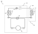
- Embodiment Fig. 1 is a refrigerant circuit diagram showing an overview of a refrigeration cycle apparatus 100 according to an embodiment. The configuration of the refrigeration cycle apparatus 100 will be described with reference to Fig. 1.
- the refrigeration cycle apparatus 100 includes an indoor unit 110 and an outdoor unit 120.
- the flow of the refrigerant in the refrigeration cycle apparatus 100 during heating operation is indicated by dashed arrows
- the flow of the refrigerant in the refrigeration cycle apparatus 100 during cooling operation is indicated by solid arrows.
- the indoor unit 110 has an indoor heat exchanger 111 that functions as an evaporator during cooling operation and as a condenser during heating operation, and an indoor blower 112.
- the outdoor unit 120 is equipped with a four-way valve 121 that switches between the refrigerant circuit during heating operation and the refrigerant circuit during cooling operation, a compressor 42 that compresses the refrigerant, a pressure reducing device 123 that reduces the pressure of the refrigerant, an outdoor heat exchanger 124 that functions as a condenser during cooling operation and as an evaporator during heating operation, and an outdoor blower 125 that blows outdoor air to the outdoor heat exchanger 124.
- the pressure reducing device 123 is an expansion valve.
- the indoor heat exchanger 111, the four-way valve 121, the compressor 42, the pressure reducing device 123, and the outdoor heat exchanger 124 are connected by piping 200 to form a refrigeration cycle in which the refrigerant circulates.
- FIG. 2 is a perspective view showing the external appearance of the outdoor unit 120 of the refrigeration cycle device 100 according to the embodiment.
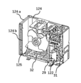
- FIG. 3 is a perspective view showing the internal structure of the outdoor unit 120 of the refrigeration cycle device 100 according to the embodiment.
- the front panel 23, top panel 26, and fan guard 27 in FIG. 2 are omitted.
- the configuration of the outdoor unit 120 will be described using FIG. 2 and FIG. 3.
- the outdoor unit 120 of the refrigeration cycle device 100 of the embodiment has a box-shaped housing 20.
- the housing 20 includes legs 21, a bottom panel 22, a front panel 23, a side panel 24, a rear panel 25, a top panel 26, and a fan guard 27.
- the legs 21 are provided on the surface on which the outdoor unit 120 is installed, and support the bottom panel 22. For example, two legs 21 are provided.
- the bottom panel 22 is provided on the upper part of the legs 21.
- the front panel 23 is placed on the bottom panel 22 and covers the front of the housing 20.
- the front panel 23 is also formed with a housing opening 23a through which air is blown out.
- the side panel 24 is placed on the bottom panel 22 and covers the side of the housing 20.
- the side panel includes a right side panel 24a that covers the right side of the housing 20 and a left side panel 24b that covers the left side of the housing 20.
- the rear panel 25 is placed on the bottom panel 22 and covers the rear of the housing 20.
- the top panel 26 is placed on the upper ends of the front panel 23, the side panel 24, and the rear panel 25, and covers the top surface of the housing 20.
- the bottom panel 22, the front panel 23, the side panel 24, the rear panel 25, and the top panel 26 are made of, for example, sheet metal.
- the fan guard 27 is a lattice-shaped member that covers the housing opening 23a formed in the front panel 23, and prevents foreign objects from entering the interior of the outdoor unit 120.
- the interior of the housing 20 is divided by a partition plate 29 into a machine chamber 31 and a heat exchange chamber 32.
- a covered compressor 122 is disposed in the machine chamber 31.
- the covered compressor 122 is mounted on the bottom panel 22.
- An outdoor heat exchanger 124 and an outdoor blower 125 are disposed in the heat exchange chamber 32.
- the outdoor heat exchanger 124 is disposed in an L-shape from the rear of the housing 20 along the left side surface.
- the outdoor heat exchanger 124 has a number of fins 124a disposed in parallel at equal intervals from one another, and piping 124b disposed perpendicular to the fins.
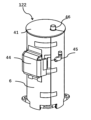
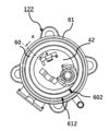
- FIG. 4 is a perspective view of a covered compressor 122 in the outdoor unit 120 of the refrigeration cycle device 100 according to an embodiment.
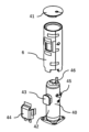
- FIG. 5 is an exploded perspective view of the covered compressor 122 in the outdoor unit 120 of the refrigeration cycle device 100 according to an embodiment. The structure of the covered compressor 122 will be described using FIG. 4 and FIG. 5.
- the covered compressor 122 has a top cover 41, a compressor 42, soundproofing material 6, and a terminal cover 44.
- the compressor 42 has a cylindrical portion 40, a terminal portion 43, a suction pipe 45, and a discharge pipe 46.
- the top cover 41 is attached to the top of the compressor 42.
- the cylindrical portion 40 of the compressor 42 has a cylindrical shape and compresses the refrigerant.
- the suction pipe 45 is attached to the top of the compressor 42 and draws in the refrigerant before compression.
- the discharge pipe 46 is attached to the top of the compressor 42 and discharges the compressed refrigerant.
- the suction pipe 45 and the discharge pipe 46 are each connected to the piping 200.
- the compressor 42 generates operating noise when compressing the refrigerant.
- the soundproofing material 6 is wrapped around the side of the compressor 42 to suppress the operating noise generated by the compressor 42.
- the structure of the soundproofing material 6 will be described later.
- the terminal cover 44 is attached to the soundproofing material 6 from the side so as to cover the terminal portion 43.
- FIG. 6 is a top view of the covered compressor 122 in the outdoor unit 120 of the refrigeration cycle apparatus 100 according to the embodiment.
- FIG. 7 is a cross-sectional view taken along line A-A in FIG. 5 of the covered compressor 122 in the outdoor unit 120 of the refrigeration cycle apparatus 100 according to the embodiment.
- FIG. 8 is an exploded view of the soundproofing material 6 in the outdoor unit 120 of the refrigeration cycle apparatus 100 according to the embodiment. The structure of the soundproofing material 6 will be described using FIGS. 6 to 8.
- the soundproofing material 6 is composed of a first soundproofing material 60 and a second soundproofing material 61. As shown in FIG. 8, the first soundproofing material 60 is fixed to the second soundproofing material 61 by a stitching portion 615. The stitching portion 615 is formed by stitching the first soundproofing material 60 and the second soundproofing material 61 together with thread.
- the stitching portion 615 is sewn in a straight line along the height direction of the compressor 42, and is provided at only one location in the circumferential direction on the side of the compressor 42.
- This configuration makes it possible to prevent deformation of the first soundproofing material 60. This is because if stitching portions were provided at multiple locations in the circumferential direction on the side of the compressor 42, the first soundproofing material 60 would deform so as to bulge toward the compressor when the soundproofing material 6 is wrapped around the compressor 42.
- the soundproofing material 6 has an opening 616.
- the opening 616 is provided to match the size and position of the terminal portion 43.
- the first soundproofing material 60 is a sheet-like member, and has a structure in which a first sound-absorbing material 600 and a first sound-insulating material 601 are combined in the thickness direction.
- the first soundproofing material 60 covers the side surface of the compressor 42.
- the first sound-absorbing material 600 attenuates the sound generated by the compressor 42, and is, for example, felt.
- the first sound-insulating material 601 blocks the sound absorbed by the first sound-absorbing material 600, and is, for example, rubber.
- the first soundproofing material 60 has a first overlapping portion 602 where one end and the other end in the circumferential direction of the side surface of the compressor 42 overlap.
- the end does not refer only to the strict end, but to an area having a certain width from the end.
- the second soundproofing material 61 is a sheet-like member, and has a structure in which a second sound-absorbing material 610 and a second sound-insulating material 611 are combined in the thickness direction.
- the second soundproofing material 61 covers the side of the compressor 42 covered with the first soundproofing material 60.
- the second sound-absorbing material 610 attenuates the sound generated by the compressor 42, and is, for example, felt.
- the second sound-insulating material 611 blocks the sound absorbed by the second sound-absorbing material 610, and is, for example, rubber.
- the second soundproofing material 61 has a second overlapping portion 612 where one end and the other end in the circumferential direction of the side of the compressor 42 overlap.
- the soundproofing materials 6 are arranged in the following order from the radial center of the compressor 42: first sound absorbing material 600, first sound insulating material 601, second sound absorbing material 610, and second sound insulating material 611. In this manner, by configuring the sound absorbing materials and sound insulating materials to be arranged alternately, the sound generated by the compressor 42 can be effectively suppressed.
- the positions of the first overlapping portion 602 and the second overlapping portion 612 are different in the circumferential direction of the side surface of the compressor 42.
- This two-layer structure with the overlapping portions at different positions can reduce leakage of operating noise from the compressor compared to a structure in which the compressor has only one layer of soundproofing material.
- Operating noise generated by the compressor 42 is blocked by the second soundproofing material 61 even if a gap occurs in the first overlapping portion 602.
- operating noise generated by the compressor 42 is blocked by the first soundproofing material 60 even if a gap occurs in the second overlapping portion 612. This is because it is possible to reduce leakage of operating noise caused by gaps in the soundproofing material.
- the second soundproofing material 61 also has a hook-and-loop fastener 613.
- the hook-and-loop fastener 613 fastens the ends of the second soundproofing material 61 together.
- the hook-and-loop fastener 613 is also positioned to cover the compressor 42. Because the first soundproofing material 60 is fixed to the second soundproofing material 61 by stitching 615, there is no need to install a hook-and-loop fastener on the first soundproofing material 60. This configuration can reduce the amount of work and the number of parts.
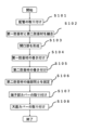
- FIG. 9 is a flowchart showing the procedure for installing the covered compressor 122, which is included in the manufacturing method for the outdoor unit 120 of the refrigeration cycle device 100 according to the embodiment.
- the procedure for installing the covered compressor 122 will be described using FIG. 9.
- the flowchart in FIG. 9 starts after the compressor 42 is manufactured. Steps S101 to S107 in FIG. 9 are performed by a person or a machine.
- step S101 the piping 200 is attached to the intake pipe 45 and the discharge pipe 46 of the compressor 42.
- Step S102 is a procedure that is performed after step S101.
- the first soundproofing material 60 and the second soundproofing material 61 are fixed together. More specifically, in step S102, the first soundproofing material 60 and the second soundproofing material 61 are sewn together with thread to form a stitched portion 615.
- Step S103 is a procedure that is performed after step S102.
- an opening 616 is formed in the soundproofing material 6.
- the position and size of the opening 616 may be determined from the position and size of the terminal portion 43.
- Step S104 is a procedure that is performed after step S103.
- the first soundproofing material 60 is wrapped around the side surface of the compressor 42 in the circumferential direction for at least one revolution.
- a first overlapping portion 602 is formed by step S104.
- Step S105 is a procedure that is performed after step S104.
- the second soundproofing material 61 is wrapped around the side surface of the compressor 42 in the circumferential direction for at least one revolution.
- a second overlapping portion 612 is formed by step S105.
- Step S106 is a procedure that is performed after step S105.
- the ends of the second soundproofing material 61 are fixed together by the hook-and-loop fastener 613. Also in step S106, the second soundproofing material 61 is positioned so as to cover the compressor 42.
- Step S107 is a procedure that is performed after step S106.
- the terminal cover 44 is attached to the soundproofing material 6.
- Step S108 is a procedure that is performed after step S107.
- the top cover 41 is attached to the top surface of the compressor 42.
- a covered compressor 122 is formed by step S108.
- the outdoor unit 120 of the refrigeration cycle apparatus 100 in the embodiment comprises a cylindrical compressor 42 that compresses a refrigerant, a first soundproofing material 60 which is a sheet-like member covering the side of the compressor 42, and a second soundproofing material 61 which is a sheet-like member covering the side of the compressor 42 covered by the first soundproofing material 60, the first soundproofing material 60 having a first joint (corresponding to the first overlapping portion 602) where one end and the other end in the circumferential direction of the side of the compressor 42 are joined, and the second soundproofing material 61 having a second joint (corresponding to the second overlapping portion 612) where one end and the other end in the circumferential direction of the side of the compressor 42 overlap, and the position of the first joint and the position of the second joint are different in the circumferential direction of the side of the compressor 42.
- This configuration allows the outdoor unit of the refrigeration cycle device according to the embodiment to have the advantage of being able to reduce the leakage of compressor operating noise more than the outdoor units of conventional refrigeration
- the manufacturing method of the outdoor unit 120 of the refrigeration cycle device 100 includes a first step (corresponding to step S101) of attaching the piping 200 of the refrigeration cycle device 100 to be connected to the suction pipe 45 and the discharge pipe 46 of the cylindrical compressor 42 that compresses the refrigerant, and a second step (corresponding to step S102) of wrapping a sheet-like first soundproofing material 60 around the side of the compressor 42 to form a first joint portion (corresponding to the first overlap portion 602) that joins one end portion and the other end portion in the circumferential direction of the side of the compressor 42.
- the method includes a second step (corresponding to step S104) of wrapping a sheet-like second soundproofing material 61 around the side of the compressor 42 covered with the first soundproofing material 60, a third step (corresponding to step S105) of forming a second joint (corresponding to the second overlapping portion 612) that joins one end and the other end at a position different from the first joint in the circumferential direction of the side of the compressor 42, and a fourth step (corresponding to step S106) of fixing one end and the other end of the second soundproofing material 61.
- the outdoor unit manufactured by the manufacturing method for the outdoor unit of the refrigeration cycle device according to the embodiment has the effect of reducing the leakage of the operating sound of the compressor compared to the outdoor unit of the conventional refrigeration cycle device.
- the outdoor unit 120 of the refrigeration cycle device 100 has, as an additional configuration, a first joint which is a first overlapping portion 602 where one end overlaps with the other end, and a second joint which is a second overlapping portion 612 where one end overlaps with the other end.
- the outdoor unit of the refrigeration cycle device according to the embodiment has the effect of suppressing the operating noise of the compressor.
- the outdoor unit 120 of the refrigeration cycle device 100 has, as an additional configuration, the first soundproofing material 60 having a first sound absorbing material 600 that attenuates the sound generated by the compressor and a first sound insulating material 601 that blocks the sound absorbed by the first sound absorbing material 600, and the second soundproofing material 61 having a second sound absorbing material 610 that attenuates the sound generated by the compressor 42 and a second sound insulating material 611 that blocks the sound absorbed by the second sound absorbing material 610.
- the outdoor unit of the refrigeration cycle device according to the embodiment has the effect of effectively reducing the leakage of the operating sound of the compressor.
- the outdoor unit 120 of the refrigeration cycle device 100 has the first sound-proofing material 60 and the second sound-proofing material 61 arranged in the order of the first sound-insulating material 601, the first sound-absorbing material 600, the second sound-insulating material 611, and the second sound-absorbing material 610 from the radial center side of the compressor 42, or in the order of the first sound-absorbing material 600, the first sound-insulating material 601, the second sound-absorbing material 610, and the second sound-insulating material 611 from the radial center side of the compressor 42.
- the outdoor unit of the refrigeration cycle device according to the embodiment has the effect of effectively suppressing the sound generated by the compressor.
- the outdoor unit 120 of the refrigeration cycle device 100 has an additional configuration in which the first soundproofing material 60 is fixed to the second soundproofing material 61 by a first fixing portion (corresponding to the stitching portion 615), and the second soundproofing material 61 is arranged to cover the compressor 42 with one end and the other end fixed by a second fixing portion (corresponding to the hook-and-loop fastener 613).
- This additional configuration provides the outdoor unit of the refrigeration cycle device according to the embodiment with the effect of reducing the number of work steps and parts.
- the outdoor unit 120 of the refrigeration cycle device 100 has a first fixing portion (corresponding to the stitching portion 615) provided at only one location in the circumferential direction on the side surface of the compressor 42.
- This additional configuration provides the outdoor unit of the refrigeration cycle device according to the embodiment with the effect of preventing deformation of the soundproofing material due to the first fixing portion.
- the manufacturing method for the outdoor unit 120 of the refrigeration cycle device 100 has, as an additional configuration, the first soundproofing material 60 having a first sound absorbing material 600 that attenuates the sound generated by the compressor and a first sound insulating material 601 that blocks the sound absorbed by the first sound absorbing material 600, and the second soundproofing material 61 having a second sound absorbing material 610 that attenuates the sound generated by the compressor 42 and a second sound insulating material 611 that blocks the sound absorbed by the second sound absorbing material 610. Due to this additional configuration, the outdoor unit manufactured by the manufacturing method for the outdoor unit of the refrigeration cycle device according to the embodiment has the effect of effectively reducing the leakage of the operating sound of the compressor.
- the manufacturing method for the outdoor unit 120 of the refrigeration cycle apparatus 100 includes, as an additional configuration, a first joint portion which is a first overlap portion 602 where one end portion overlaps with the other end portion, and a second joint portion which is a second overlap portion 612 where one end portion overlaps with the other end portion. Due to this additional configuration, the outdoor unit manufactured by the manufacturing method for the outdoor unit of the refrigeration cycle apparatus according to the embodiment has the effect of suppressing the operating noise of the compressor.
- the manufacturing method for the outdoor unit 120 of the refrigeration cycle device 100 has an additional configuration in which the first soundproofing material 60 and the second soundproofing material 61 are arranged in the order of the first sound-insulating material 601, the first sound-absorbing material 600, the second sound-insulating material 611, and the second sound-absorbing material 610 from the radial center side of the compressor 42, or in the order of the first sound-absorbing material 600, the first sound-insulating material 601, the second sound-absorbing material 610, and the second sound-insulating material 611 from the radial center side of the compressor 42.
- the outdoor unit manufactured by the manufacturing method for the outdoor unit of the refrigeration cycle device according to the embodiment has the effect of effectively suppressing the sound generated by the compressor.
- the manufacturing method for the outdoor unit 120 of the refrigeration cycle device 100 includes an additional configuration in which the first soundproofing material 60 is fixed to the second soundproofing material 61 by a first fixing portion (corresponding to the stitching portion 615), and the second soundproofing material 61 is arranged to cover the compressor 42 with one end and the other end fixed by a second fixing portion (corresponding to the hook-and-loop fastener 613).
- This additional configuration provides the effect of reducing the number of work steps and parts in the manufacturing method for the outdoor unit of the refrigeration cycle device according to the embodiment.
- the first fixing portion (corresponding to the stitching portion 615) is provided at only one location in the circumferential direction on the side surface of the compressor 42. Due to this additional configuration, the outdoor unit manufactured by the manufacturing method for the outdoor unit of the refrigeration cycle apparatus according to the embodiment has the effect of preventing deformation of the soundproofing material due to the first fixing portion.
- the refrigeration cycle device has a four-way valve and is configured to be able to switch between cooling operation and heating operation, but this is not limited to this.
- the refrigeration cycle device may not have a four-way valve and may be configured to perform only cooling operation or heating operation.
- the first soundproofing material is fixed to the second soundproofing material by sewing the seams, but the fixing method is not limited to this. Any method may be used as long as the first soundproofing material and the second soundproofing material are fixed at one location in the circumferential direction of the compressor.
- the first soundproofing material and the second soundproofing material may be fixed with a stapler.
- the soundproofing material is fixed to the compressor using hook-and-loop fasteners, but this is not limited to this. Any method can be used as long as it can secure the soundproofing material to the compressor. For example, it may be secured using threaded tacks or hooks.
- the ends of the second soundproofing material are fixed together by the hook-and-loop fastener, but this is not limited to the above.
- the first soundproofing material may have a hook-and-loop fastener as well as the second soundproofing material, and the ends of the first soundproofing material may be fixed together.
- the soundproofing materials are arranged in the following order from the center in the circumferential direction of the compressor: first sound absorbing material, first sound insulating material, second sound absorbing material, second sound insulating material.
- first sound absorbing material first sound insulating material
- second sound absorbing material second sound insulating material
- the combination of sound absorbing materials and sound insulating materials is determined by the designer.
- the order from the inside in the circumferential direction of the compressor may be first sound insulating material, first sound absorbing material, second sound insulating material, second sound absorbing material.
- the number of sound absorbing materials and sound insulating materials may be different.
- first sound insulating material there may be two sound absorbing materials and three sound insulating materials, and the order from the inside in the circumferential direction of the compressor may be first sound insulating material, first sound absorbing material, second sound insulating material, third sound insulating material, second sound absorbing material. Note that even in this order, it is included in the case where the first sound insulating material, first sound absorbing material, second sound insulating material, second sound absorbing material are arranged in this order from the center in the radial direction of the compressor.
- the first soundproofing material has a first overlapping portion
- the second soundproofing material has a second overlapping portion
- the first soundproofing material and the second soundproofing material do not need to have an overlapping portion, as long as they have a joint where the ends are joined together.
- one end of the soundproofing material and the other end of the soundproofing material may be butted together, and the ends may be joined together so that no overlapping portion is created.
- the soundproofing material has a two-layer structure of a first soundproofing material and a second soundproofing material, but this is not limited to this.
- the soundproofing material may have two or more layers.
- the terminal section and the terminal section cover are provided on the side of the compressor, but this is not limited to the configuration.
- the terminal section and the terminal section cover may be provided on the top surface of the compressor. In that case, the top cover has an opening corresponding to the terminal section.
- the sutured portion and the opening are formed after the piping is attached, but this is not limited to the above.
- the piping may be attached after the sutured portion and the opening are formed. Any configuration may be used as long as the soundproofing material is attached after the piping is attached.
- the first soundproofing material is wrapped around the side of the compressor in the circumferential direction at least once, and then the second soundproofing material is wrapped around the side of the compressor in the circumferential direction at least once, but this is not limited to the above.
- the first soundproofing material and the second soundproofing material may be wrapped around simultaneously. This is because the circumferential lengths of the first soundproofing material and the second soundproofing material are predetermined, and the positional relationship between the first overlapping portion and the second overlapping portion can be uniquely determined by the stitching.
- 6 soundproofing material 20 housing, 21 legs, 22 bottom panel, 23 front panel, 23a housing opening, 24 side panel, 24a right side panel, 24b left side panel, 25 rear panel, 26 top panel, 27 fan guard, 29 partition plate, 31 machine room, 32 heat exchange room, 40 cylindrical part, 41 top cover, 42 compressor, 43 terminal part, 44 terminal part cover, 45 intake pipe, 46 discharge pipe, 60 first soundproofing material, 61 second soundproofing material, 100 refrigeration cycle device, 110 indoor unit, 111 indoor heat exchanger, 112 indoor blower, 120 outdoor unit, 121 four-way valve, 122 covered compressor, 123 pressure reducing device, 124 outdoor heat exchanger, 124a fin, 124b piping, 125 outdoor blower, 200 piping, 600 first sound absorbing material, 601 first sound insulating material, 602 first overlapping portion, 610 second sound absorbing material, 611 second sound insulating material, 612 second overlapping portion, 613 hook-and-loop fastener, 615 stitching portion, 616 opening
Landscapes
- Engineering & Computer Science (AREA)
- Mechanical Engineering (AREA)
- General Engineering & Computer Science (AREA)
- Physics & Mathematics (AREA)
- Thermal Sciences (AREA)
- Chemical & Material Sciences (AREA)
- Combustion & Propulsion (AREA)
- Compressor (AREA)
Priority Applications (2)
| Application Number | Priority Date | Filing Date | Title |
|---|---|---|---|
| JP2023578945A JP7722478B2 (ja) | 2023-04-19 | 2023-04-19 | 冷凍サイクル装置の室外機及び冷凍サイクル装置の室外機の製造方法 |
| PCT/JP2023/015591 WO2024218890A1 (ja) | 2023-04-19 | 2023-04-19 | 冷凍サイクル装置の室外機及び冷凍サイクル装置の室外機の製造方法 |
Applications Claiming Priority (1)
| Application Number | Priority Date | Filing Date | Title |
|---|---|---|---|
| PCT/JP2023/015591 WO2024218890A1 (ja) | 2023-04-19 | 2023-04-19 | 冷凍サイクル装置の室外機及び冷凍サイクル装置の室外機の製造方法 |
Publications (1)
| Publication Number | Publication Date |
|---|---|
| WO2024218890A1 true WO2024218890A1 (ja) | 2024-10-24 |
Family
ID=93152478
Family Applications (1)
| Application Number | Title | Priority Date | Filing Date |
|---|---|---|---|
| PCT/JP2023/015591 Ceased WO2024218890A1 (ja) | 2023-04-19 | 2023-04-19 | 冷凍サイクル装置の室外機及び冷凍サイクル装置の室外機の製造方法 |
Country Status (2)
| Country | Link |
|---|---|
| JP (1) | JP7722478B2 (https=) |
| WO (1) | WO2024218890A1 (https=) |
Citations (5)
| Publication number | Priority date | Publication date | Assignee | Title |
|---|---|---|---|---|
| JPH0965724A (ja) * | 1995-08-31 | 1997-03-11 | Kubota Corp | 田植機 |
| JPH11159813A (ja) * | 1997-11-26 | 1999-06-15 | Daikin Ind Ltd | 空気調和機 |
| JP2013088002A (ja) * | 2011-10-17 | 2013-05-13 | Daikin Industries Ltd | 室外機 |
| WO2020021625A1 (ja) * | 2018-07-24 | 2020-01-30 | 三菱電機株式会社 | 防音部材及び空気調和機の室外機 |
| WO2021001925A1 (ja) * | 2019-07-02 | 2021-01-07 | 三菱電機株式会社 | 空気調和機の室外機 |
Family Cites Families (4)
| Publication number | Priority date | Publication date | Assignee | Title |
|---|---|---|---|---|
| JPS61180411A (ja) * | 1985-02-05 | 1986-08-13 | Toshiba Corp | 巻鉄心構成体の製造方法 |
| JPH04133404U (ja) * | 1991-06-03 | 1992-12-11 | 鐘淵化学工業株式会社 | 磁性ゴムロール |
| JP6736947B2 (ja) * | 2016-03-30 | 2020-08-05 | 株式会社富士通ゼネラル | 空気調和機の室外機 |
| WO2021214942A1 (ja) * | 2020-04-23 | 2021-10-28 | 三菱電機株式会社 | 空気調和機の室外機 |
-
2023
- 2023-04-19 JP JP2023578945A patent/JP7722478B2/ja active Active
- 2023-04-19 WO PCT/JP2023/015591 patent/WO2024218890A1/ja not_active Ceased
Patent Citations (5)
| Publication number | Priority date | Publication date | Assignee | Title |
|---|---|---|---|---|
| JPH0965724A (ja) * | 1995-08-31 | 1997-03-11 | Kubota Corp | 田植機 |
| JPH11159813A (ja) * | 1997-11-26 | 1999-06-15 | Daikin Ind Ltd | 空気調和機 |
| JP2013088002A (ja) * | 2011-10-17 | 2013-05-13 | Daikin Industries Ltd | 室外機 |
| WO2020021625A1 (ja) * | 2018-07-24 | 2020-01-30 | 三菱電機株式会社 | 防音部材及び空気調和機の室外機 |
| WO2021001925A1 (ja) * | 2019-07-02 | 2021-01-07 | 三菱電機株式会社 | 空気調和機の室外機 |
Also Published As
| Publication number | Publication date |
|---|---|
| JPWO2024218890A1 (https=) | 2024-10-24 |
| JP7722478B2 (ja) | 2025-08-13 |
Similar Documents
| Publication | Publication Date | Title |
|---|---|---|
| JP2738521B2 (ja) | 空気調和機の室外機 | |
| JP2005241236A (ja) | 空調機の室外機の配管構造 | |
| KR101838077B1 (ko) | 압축기의 방음커버 및 이를 포함하는 공기조화기 | |
| JP6925534B2 (ja) | 防音部材及び空気調和機の室外機 | |
| JP7722478B2 (ja) | 冷凍サイクル装置の室外機及び冷凍サイクル装置の室外機の製造方法 | |
| CN112166250B (zh) | 压缩机单元、空调装置的室外机以及空调装置 | |
| JP2010038460A (ja) | 空気調和装置の室外ユニット | |
| JP6745910B2 (ja) | 空気調和機の室外機及び空気調和機の室外機の組立方法 | |
| JP7282263B2 (ja) | 空気調和機の室外機 | |
| JP2013087999A (ja) | 室外機 | |
| JP2011094955A (ja) | ヒートポンプ式熱源機ユニット | |
| JP2009204238A (ja) | 空気調和機における配管構造 | |
| JP2005214615A (ja) | 空調機の配管構造 | |
| JP3519783B2 (ja) | エンジン駆動式空気調和装置 | |
| JPH11159813A (ja) | 空気調和機 | |
| JP2002005558A (ja) | 冷蔵庫及び冷蔵庫の製造方法 | |
| KR20140100044A (ko) | 압축기 소음방지 커버 및 이를 포함하는 공기조화기 | |
| JP2017156038A (ja) | 防音カバー及びそれを備えた室外ユニット | |
| AU2017246781B2 (en) | Outdoor unit of air conditioning system | |
| CN218296022U (zh) | 空调器 | |
| JP2004251587A (ja) | 空気調和機の室外機 | |
| US20250198648A1 (en) | Air conditioner and component unit | |
| KR100423605B1 (ko) | 에어컨 실외기의 응축기 고정구조 | |
| KR20020047699A (ko) | 방음장치를 갖는 공기조화기 및 그 제조방법 | |
| JP7097973B2 (ja) | 室内機及び冷凍サイクル装置 |
Legal Events
| Date | Code | Title | Description |
|---|---|---|---|
| WWE | Wipo information: entry into national phase |
Ref document number: 2023578945 Country of ref document: JP |
|
| 121 | Ep: the epo has been informed by wipo that ep was designated in this application |
Ref document number: 23934036 Country of ref document: EP Kind code of ref document: A1 |
|
| NENP | Non-entry into the national phase |
Ref country code: DE |
|
| 122 | Ep: pct application non-entry in european phase |
Ref document number: 23934036 Country of ref document: EP Kind code of ref document: A1 |