WO2024209656A1 - 端末、基地局、及び通信方法 - Google Patents
端末、基地局、及び通信方法 Download PDFInfo
- Publication number
- WO2024209656A1 WO2024209656A1 PCT/JP2023/014310 JP2023014310W WO2024209656A1 WO 2024209656 A1 WO2024209656 A1 WO 2024209656A1 JP 2023014310 W JP2023014310 W JP 2023014310W WO 2024209656 A1 WO2024209656 A1 WO 2024209656A1
- Authority
- WO
- WIPO (PCT)
- Prior art keywords
- terminal
- base station
- wus
- wake
- ultra
- Prior art date
- Legal status (The legal status is an assumption and is not a legal conclusion. Google has not performed a legal analysis and makes no representation as to the accuracy of the status listed.)
- Ceased
Links
Images







Classifications
-
- Y—GENERAL TAGGING OF NEW TECHNOLOGICAL DEVELOPMENTS; GENERAL TAGGING OF CROSS-SECTIONAL TECHNOLOGIES SPANNING OVER SEVERAL SECTIONS OF THE IPC; TECHNICAL SUBJECTS COVERED BY FORMER USPC CROSS-REFERENCE ART COLLECTIONS [XRACs] AND DIGESTS
- Y02—TECHNOLOGIES OR APPLICATIONS FOR MITIGATION OR ADAPTATION AGAINST CLIMATE CHANGE
- Y02D—CLIMATE CHANGE MITIGATION TECHNOLOGIES IN INFORMATION AND COMMUNICATION TECHNOLOGIES [ICT], I.E. INFORMATION AND COMMUNICATION TECHNOLOGIES AIMING AT THE REDUCTION OF THEIR OWN ENERGY USE
- Y02D30/00—Reducing energy consumption in communication networks
- Y02D30/70—Reducing energy consumption in communication networks in wireless communication networks
Definitions
- the present invention relates to a terminal, a base station, and a communication method in a wireless communication system.
- 3GPP registered trademark
- 3rd Generation Partnership Project 3rd Generation Partnership Project
- 5G Fifth Generation Partnership Project
- NR New Radio
- 5G various wireless technologies and network architectures are being studied to meet the requirements of achieving a throughput of 10 Gbps or more while keeping latency in wireless sections to 1 ms or less (for example, Non-Patent Document 1 and Non-Patent Document 2).
- the present invention has been made in consideration of the above points, and aims to specify a method for transmitting and retransmitting LP-WUS in a wireless communication system.
- the disclosed technology provides a terminal having a receiver that receives an ultra-low power wakeup signal, including an instruction not to wake up, from a base station in a resource of a predetermined period, which is transmitted as necessary, and a controller that assumes that there is an instruction to wake up if the ultra-low power wakeup signal is not received in the resource.
- the disclosed technology makes it possible to specify the transmission and retransmission methods of LP-WUS in a wireless communication system.
- 1 is a diagram illustrating a wireless communication system according to an embodiment of the present invention.
- 1 is a diagram illustrating a wireless communication system according to an embodiment of the present invention.
- 1 is a diagram for explaining a LP-WUS transmission method in an embodiment of the present invention.
- 1 is a diagram for explaining a LP-WUS transmission method in an embodiment of the present invention.
- FIG. 1 is a sequence diagram illustrating an example of a method for transmitting an LP-WUS according to a first embodiment of the present invention.
- FIG. 11 is an example of a sequence diagram relating to a method of transmitting an LP-WUS in an embodiment 1-1a of the present invention.
- 11 is an example of a sequence diagram relating to a method of transmitting an LP-WUS in an embodiment 1-1b of the present invention.
- 11 is an example of a sequence diagram relating to a method of transmitting an LP-WUS in an embodiment 1-1c of the present invention.
- 13 is an example of a sequence diagram relating to a method of transmitting an LP-WUS in embodiment 1-2 of the present invention.
- FIG. 11 is an example of a sequence diagram relating to a method of transmitting an LP-WUS in an embodiment 1-1a of the present invention.
- 11 is an example of a sequence diagram relating to a method of transmitting an LP-WUS in an embodiment 1-1
- FIG. 11 is an example of a sequence diagram relating to a method of transmitting an LP-WUS in accordance with an embodiment 1-3 of the present invention.
- FIG. 11 is an example of a sequence diagram relating to a method of transmitting an LP-WUS in accordance with an embodiment 1-4 of the present invention.
- 13 is an example of a sequence diagram relating to a method of transmitting an LP-WUS in the second embodiment of the present invention.
- 13 is an example of a sequence diagram relating to a method of transmitting an LP-WUS in a third embodiment of the present invention.
- FIG. 2 is a diagram illustrating an example of a functional configuration of a base station 10 according to an embodiment of the present invention.
- FIG. 1 is an example of a functional configuration of a base station 10 according to an embodiment of the present invention.
- FIG. 2 is a diagram illustrating an example of a functional configuration of a terminal 20 according to an embodiment of the present invention.
- 2 is a diagram illustrating an example of a hardware configuration of a base station 10 or a terminal 20 according to an embodiment of the present invention.
- FIG. 2 is a diagram showing an example of the configuration of a vehicle 2001 according to an embodiment of the present invention.
- LTE Long Term Evolution
- NR NR
- SS Synchronization signal
- PSS Primary SS
- SSS Secondary SS
- PBCH Physical broadcast channel
- PRACH Physical random access channel
- PDCCH Physical Downlink Control Channel
- PDSCH Physical Downlink Shared Channel
- PUCCH Physical Uplink Control Channel
- PUSCH Physical Uplink Shared Channel
- the duplex method may be a TDD (Time Division Duplex) method, an FDD (Frequency Division Duplex) method, or another method (e.g., Flexible Duplex, etc.).
- TDD Time Division Duplex
- FDD Frequency Division Duplex
- another method e.g., Flexible Duplex, etc.
- "configuring" radio parameters and the like may mean that a predetermined value is pre-configured, or that radio parameters notified from the base station 10 or the terminal 20 are set.
- the base station 10 or the terminal 20 may pre-configure a fixed value defined in the 3GPP standard/specification, or if multiple usable values are defined, the base station 10 may notify the terminal 20 of the value that it sets, or the terminal 20 may notify the base station 10 of a usable value.
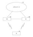
- FIG. 1 is a diagram showing an example of the configuration of a wireless communication system in an embodiment of the present invention.
- the wireless communication system in the embodiment of the present invention includes a base station 10 and a terminal 20.
- FIG. 1 shows one base station 10 and one terminal 20, this is an example, and there may be multiple of each.
- the base station 10 is a communication device that provides one or more cells and performs wireless communication with the terminal 20.
- the physical resources of a wireless signal are defined in the time domain and the frequency domain, and the time domain may be defined by the number of OFDM (Orthogonal Frequency Division Multiplexing) symbols, and the frequency domain may be defined by the number of subcarriers or the number of resource blocks.
- the base station 10 transmits a synchronization signal and system information to the terminal 20.
- the synchronization signal is, for example, a PSS and an SSS.
- the system information is, for example, transmitted by the PBCH and is also called broadcast information.
- the synchronization signal and the system information may be called an SSB (SS/PBCH block). As shown in FIG.
- the base station 10 transmits a control signal or data to the terminal 20 in the DL (Downlink) and receives a control signal or data from the terminal 20 in the UL (Uplink). Both the base station 10 and the terminal 20 are capable of transmitting and receiving signals by performing beamforming. In addition, both the base station 10 and the terminal 20 can apply MIMO (Multiple Input Multiple Output) communication to DL or UL. In addition, both the base station 10 and the terminal 20 may communicate via a secondary cell (SCell: Secondary Cell) and a primary cell (PCell: Primary Cell) using CA (Carrier Aggregation). Furthermore, the terminal 20 may communicate via a primary cell of the base station 10 and a primary secondary cell group cell (PSCell: Primary SCG Cell) of another base station 10 using DC (Dual Connectivity).
- SCell Secondary Cell
- PCell Primary Cell
- CA Carrier Aggregation
- the terminal 20 may communicate via a primary cell of the base station 10 and a primary secondary cell group cell (PSCell: Primary SCG Cell) of another base
- the terminal 20 is a communication device equipped with a wireless communication function, such as a smartphone, a mobile phone, a tablet, a wearable terminal, or a communication module for M2M (Machine-to-Machine). As shown in FIG. 1, the terminal 20 receives control signals or data from the base station 10 in DL and transmits control signals or data to the base station 10 in UL, thereby utilizing various communication services provided by the wireless communication system. The terminal 20 also receives various reference signals transmitted from the base station 10, and performs measurement of the propagation path quality based on the reception results of the reference signals.
- M2M Machine-to-Machine
- FIG. 2 is a diagram for explaining a wireless communication system in an embodiment of the present invention.
- Figure 2 shows an example of the configuration of a wireless communication system when DC (Dual connectivity) is implemented.
- base station 10A which is an MN (Master Node)
- base station 10B which is an SN (Secondary Node).
- Base station 10A and base station 10B are each connected to a core network.
- Terminal 20 can communicate with both base station 10A and base station 10B.
- the cell group provided by base station 10A which is an MN
- the MCG Master Cell Group
- the cell group provided by base station 10B which is an SN
- the SCG Secondary Cell Group
- the MCG is composed of one PCell and one or more SCells
- the SCG is composed of one PSCell (Primary SCG Cell) and one or more SCells.
- processing operations in this embodiment may be executed in the system configuration shown in FIG. 1, in the system configuration shown in FIG. 2, or in other system configurations.
- "/” means “or” unless otherwise specified or unless it is clear from the context that it has a different meaning.
- FIG. 3 is a diagram for explaining communication by LP-WUS and LP-WUR in an embodiment of the present invention.
- 3GPP registered trademark
- Rel-18 a power consumption reduction technology called "Low-Power Wake Up Signal and Receiver” is under discussion.
- Low-Power Wake Up Signal is called LP-WUS or simply WUS
- Low-Power Wake Up Receiver is called LP-WUR, WUR, or LR.
- a state called Ultra-Deep Sleep is introduced by operating the LR, a simple circuit that operates with lower power consumption than the Main Radio (MR) used in normal communication, as a replacement for the MR.
- MR Main Radio
- the LR will have a function that triggers the power ON of the MR when the LR receives at least an LP-WUS signal.
- the RACH procedure may continue, such as transmitting a PRACH as an operation for RRC IDLE, or the PDCCH monitoring operation may continue, such as an operation for RRC CONNECTED.
- Figure 4 is a diagram for explaining communication by LP-WUS and LP-WUR in an embodiment of the present invention. Details of the functions that LR should have are currently under discussion in 3GPP, including what states (such as RRC IDLE and RRC CONNECTED) the functions should be expanded for, whether functions other than monitoring LP-WUS and waking up MR are necessary, and which functions of MR should be substituted by LR in Ultra-Deep Sleep state (for example, RRM in RRC IDLE state). As a possible candidate function under consideration, it is being considered to transmit an LP-WUS containing information indicating whether PO should be monitored, as shown in Figure 4, and for the LR to receive the LP-WUS, start up the MR, and continue monitoring the PO thereafter.
- states such as RRC IDLE and RRC CONNECTED
- 3GPP does not specify the method of transmitting LP-WUS or the operation to be performed if an error occurs during reception. If an error occurs during reception, a transmission method of resending LP-WUS is possible, but this would require securing new resources for retransmission.
- Fig. 5 is a diagram for explaining a method of transmitting an LP-WUS in an embodiment of the present invention.
- the base station 10 sets setting information including information on the range of resources that can be transmitted by the LP-WUS, and transmits the LP-WUS to the terminal 20 at a necessary timing within the set resource range based on the setting information.
- the terminal 20 sets resources for receiving the LP-WUS based on the setting information including information on the range of resources that can be transmitted by the LP-WUS received from the base station 10, and receives the LP-WUS transmitted from the base station 10.
- the LP-WUS transmitted in Fig. 5 is, for example, a signal instructing to wake up the MR (to turn on the power).
- the LP-WUS may also include information regarding a terminal identifier (UE_ID) indicating the target terminal 20 to be instructed, or a terminal group identifier (UE_group_ID) indicating a group of target terminals 20 to be instructed, and the LP-WUS may specify multiple UE_IDs or multiple UE_group_IDs.
- UE_ID terminal identifier
- UE_group_ID terminal group identifier
- an LP-WUS multiplexed from a single LP-WUS may be generated and transmitted using time division multiplexing (TDM), frequency division multiplexing (FDM), code division multiplexing (CDM), etc.
- FIG. 6 is a diagram for explaining a method of transmitting an LP-WUS in an embodiment of the present invention.
- the base station 10 sets configuration information including information on opportunities when an LP-WUS can be transmitted (LP-WUS occasions), and transmits an LP-WUS to the terminal 20 at the required timing within the set resource range based on the configuration information.
- LP-WUS occasions have a certain time period.
- the terminal 20 sets resources for receiving an LP-WUS based on the configuration information received from the base station 10 including information on opportunities when an LP-WUS can be transmitted (LP-WUS occasions), and receives the LP-WUS transmitted from the base station 10.
- LP-WUS occasions For example, LP-WUS occasions have a certain time period.
- the terminal 20 sets resources for receiving an LP-WUS based on the configuration information received from the base station 10 including information on opportunities when an LP-WUS can be transmitted (LP-WUS occasions), and receives the LP-WUS transmitted from the base station 10.
- LP-WUS (OFF) which instructs the MR not to be woken up (to be powered ON) may be transmitted.
- LP-WUS (OFF) may also be an instruction to continue powering OFF.
- the base station 10 may transmit an LP-WUS (LP-WUS(ON) or LP-WUS(OFF)) at every opportunity when an LP-WUS can be transmitted, as shown in FIG. 6(a).
- the base station 10 may transmit an LP-WUS only when necessary at an opportunity when an LP-WUS can be transmitted, as shown in FIG. 6(b).
- the base station 10 transmits an LP-WUS(ON) indicated by the solid line rectangle, but does not transmit an LP-WUS(OFF) indicated by the dotted line rectangle.
- FIG. 7 is a diagram for explaining the format of an LP-WUS in an embodiment of the present invention.
- FIG. 7 shows five types of LP-WUS formats including a preamble and a payload.
- the preamble is a signal for the terminal 20 to detect the LP-WUS.
- the payload includes, for example, information instructing the aforementioned MR to be woken up (to turn the power ON), information instructing the MR not to be woken up (to not turn the power ON), a terminal identifier (UE_ID) indicating the terminal 20 to be instructed, and information regarding a terminal group identifier (UE_group_ID) indicating the group of the terminal 20 to be instructed.
- UE_ID terminal identifier
- UE_group_ID terminal group identifier
- the preamble and payload are transmitted when requested.
- the request may be when the base station 10 requests wake-up of the MR, or when the LP-WUS is transmitted irregularly due to other triggers. The same applies hereafter.
- the preamble is sent periodically and the payload is sent on request.
- the third format involves a preamble that is sent periodically followed by another preamble and payload upon request.
- the preamble, which is sent periodically, and the payload, which is sent upon request, are each sent as separate signals.
- the preamble, which is a separate signal may be called LP-SS (Low Power - Synchronization Signal).
- the preamble and payload are transmitted periodically.
- Example 1 A first embodiment will be described.
- the base station 10 transmits an LP-WUS (LP-WUS(ON) or LP-WUS(OFF)) to the terminal 20, which instructs the terminal 20 to wake up or not wake up the MR, on all occasions in the LP-WUS occasions having a certain time period.
- the terminal 20 may also notify the base station 10 that the reception of the LP-WUS is successful (ACK, success response) or unsuccessful (NACK, failure response).
- FIG. 8 is an example of a sequence diagram relating to a method of transmitting an LP-WUS in the first embodiment of the present invention. This sequence is for a case where no error occurs on the receiving side. The processing of each step will be described below.
- Step S30 The base station 10 transmits an LP-WUS(ON) to the terminal 20, which instructs the terminal 20 to wake up the MR.
- Step S31 The terminal 20 receives the LP-WUS(ON) sent by the base station 10 in step S30, and sends an ACK to the base station 10 to notify that the LP-WUS(ON) was successfully received.
- Step S32 The base station 10 transmits LP-WUS(OFF) to the terminal 20, which instructs the terminal 20 not to wake up the MR.
- Step S33 The terminal 20 receives the LP-WUS(OFF) sent by the base station 10 in step S32, and sends an ACK to the base station 10 to notify that the LP-WUS(OFF) was successfully received.
- Example 1-1a An example 1-1a will be described.
- An example of an error occurring on the receiving side is, for example, a case where some signal is received, but an error is detected by an error detection process, and therefore the signal cannot be received correctly.
- An example of an error occurring on the receiving side is sometimes called a case where reception is not possible, or a case where reception fails.
- the terminal 20 instructs the base station 10 to retransmit the LP-WUS by transmitting a NACK to the base station 10.
- FIG. 9 is an example of a sequence diagram relating to a method for transmitting an LP-WUS in the example 1-1a of the present invention. The processing of each step will be described below.
- Step S40 The base station 10 transmits an LP-WUS(ON) to the terminal 20, which instructs the terminal 20 to wake up the MR.
- Step S41 The terminal 20 is unable to receive the LP-WUS transmitted by the base station 10 in step S40, and transmits a NACK to the base station 10 to notify that reception of the LP-WUS has failed.
- Step S42 In response to the NACK transmitted by the terminal 20 in step S41, the base station 10 retransmits the LP-WUS(ON) transmitted in step S40 to the terminal 20 using a predetermined retransmission resource.
- Step S43 The base station 10 transmits LP-WUS(OFF) to the terminal 20, which instructs the terminal 20 not to wake up the MR.
- Step S44 The terminal 20 receives the LP-WUS(OFF) sent by the base station 10 in step S43, and sends an ACK to the base station 10 to notify that the LP-WUS(OFF) was successfully received.
- Example 1-1b An example 1-1b will be described.
- the terminal 20 fails to receive the LP-WUS at a timing of a predetermined period, the terminal 20 transmits a NACK to the base station 10 to instruct the base station 10 to retransmit the LP-WUS.
- the base station 10 transmits to the terminal 20 an LP-WUS that is multiplexed with the LP-WUS that was previously unsuccessfully received.
- FIG. 10 is an example of a sequence diagram relating to a method for transmitting an LP-WUS in the example 1-1b of the present invention. The processing of each step will be described below.
- Step S50 The base station 10 transmits an LP-WUS(ON) to the terminal 20, which instructs the terminal 20 to wake up the MR.
- Step S51 The terminal 20 is unable to receive the LP-WUS transmitted by the base station 10 in step S50, and transmits a NACK to the base station 10 to notify that reception of the LP-WUS has failed.
- Step S52 In response to the NACK sent by terminal 20 in step S51, base station 10 transmits to terminal 20 a LP-WUS that is a multiplexed version of the LP-WUS that failed to be received in step S51 in the next LP-WUS to be transmitted.
- a LP-WUS that is a multiplexed version of the LP-WUS that failed to be received in step S51 in the next LP-WUS to be transmitted.
- the LP-WUS sent in step S50 and the LP-WUS that was scheduled to be sent in step S52 is LP-WUS(ON)
- base station 10 sets the multiplexed LP-WUS to LP-WUS(ON), and otherwise sets it to LP-WUS(OFF).
- the LP-WUS contains instructions for multiple terminals 20, or if it contains instructions for at least one terminal group
- the multiplexed LP-WUS is set to LP-WUS(ON), and if not, it is set to LP-WUS(OFF), so that ON or OFF is determined for each target of the instruction (terminal or terminal group).
- Step S53 The terminal 20 receives the LP-WUS(ON, multiplexed) sent by the base station 10 in step S52, and sends an ACK to the base station 10 to notify that the LP-WUS(ON, multiplexed) was successfully received.
- Example 1-1c An example 1-1c will be described.
- the terminal 20 fails to receive the LP-WUS at a timing of a predetermined period, the terminal 20 transmits a NACK to the base station 10 to instruct the base station 10 to retransmit the LP-WUS.
- the base station 10 transmits a retransmission instruction including information instructing the resource of the LP-WUS to be retransmitted to the terminal 20, and then retransmits the LP-WUS to the terminal 20 using the instructed resource.
- FIG. 11 is an example of a sequence diagram relating to a method for transmitting an LP-WUS in the example 1-1c of the present invention. The processing of each step will be described below.
- Step S60 The base station 10 transmits an LP-WUS(ON) to the terminal 20, which instructs the terminal 20 to wake up the MR.
- Step S61 The terminal 20 is unable to receive the LP-WUS transmitted by the base station 10 in step S60, and transmits a NACK to the base station 10 to notify that reception of the LP-WUS has failed.
- Step S62 In response to the NACK transmitted by the terminal 20 in step S61, the base station 10 transmits a retransmission instruction to the terminal 20, the retransmission instruction including information indicating the LP-WUS resource to be retransmitted.
- Step S63 The base station 10 retransmits the LP-WUS sent in step S60 to the terminal 20 using the resources instructed in step S62.
- Step S64 The base station 10 transmits LP-WUS(OFF) to the terminal 20, which instructs the terminal 20 not to wake up the MR.
- Step S65 The terminal 20 receives the LP-WUS(OFF) sent by the base station 10 in step S64, and sends an ACK to the base station 10 to notify that the LP-WUS(OFF) was successfully received.
- Example 1-2 An example 1-2 will be described.
- the terminal 20 fails to receive the LP-WUS at a timing of a predetermined cycle, the terminal 20 transmits a NACK to the base station 10 to instruct the base station 10 to retransmit the LP-WUS.
- the base station 10 Based on the received NACK, the base station 10 transmits a stop instruction to the terminal 20 to stop the transmission of the LP-WUS.
- the period for stopping the transmission of the LP-WUS may be a predetermined period, or the stop instruction may include information on the period for stopping.
- the terminal 20 may resume the transmission of the LP-WUS by transmitting a resume request to the base station 10 to request the base station 10 to resume the transmission of the LP-WUS.
- FIG. 12 is an example of a sequence diagram relating to a method for transmitting an LP-WUS in the example 1-2 of the present invention. The processing of each step will be described below.
- Step S70 The base station 10 transmits an LP-WUS(ON) to the terminal 20, which instructs the terminal 20 to wake up the MR.
- Step S71 The terminal 20 is unable to receive the LP-WUS transmitted by the base station 10 in step S70, and transmits a NACK to the base station 10 to notify that reception of the LP-WUS has failed.
- Step S72 In response to the NACK sent by the terminal 20 in step S71, the base station 10 sends a stop instruction to the terminal 20 to instruct it to stop transmitting the LP-WUS.
- Step S73 The terminal 20 transmits a resume request to the base station 10, requesting the resumption of LP-WUS transmission.
- the terminal 20 may set a threshold value for the reception strength of, for example, RSRP (Reference Signals Received Power), and when it determines that the threshold value is exceeded, request the base station 10 to resume LP-WUS transmission.
- RSRP Reference Signals Received Power
- Step S74 In response to the resume request received from the terminal 20, the base station 10 resumes LP-WUS transmission and transmits LP-WUS(OFF) to the terminal 20, which instructs the terminal 20 not to wake up the MR.
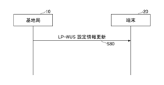
- Example 1-3 the base station 10 transmits an instruction to update the configuration information (configuration) related to the LP-WUS to the terminal 20.
- FIG. 13 is an example of a sequence diagram related to the transmission method of the LP-WUS in Example 1-3 of the present invention.
- step S80 the base station 10 transmits an instruction to update the configuration information related to the LP-WUS to the terminal 20.
- the configuration information includes parameters related to, for example, the transmission strength (transmission power) of the LP-WUS, the transmission period, the format, and the payload size, and the base station 10 transmits the configuration information with the updated values of these parameters to the terminal 20.
- the base station 10 may estimate the reception status according to the ACK and NACK received from the terminal 20 and update the parameter values of the configuration information. For example, if the base station 10 receives many ACKs, it estimates that the reception status is good and increases the transmission strength, and if it receives many NACKs, it estimates that the reception status is bad and decreases the transmission strength, and performs other adjustments.
- the setting information for the LP-WUS can be updated according to the reception conditions of the terminal 20, making it possible to effectively utilize wireless resources.
- the terminal 20 may execute the ACK/NACK instruction indicating whether or not the LP-WUS has been received based on an existing signal and channel (PDCCH or PUCCH, etc.), or may execute the instruction using a newly introduced signal and channel.
- the WUR Wood Up Receiver
- the WUR may start the MR (Main Radio), and as a result, the WUR may be turned off, and monitoring of the LP-WUS by the WUR may be stopped.
- the base station 10 may implicitly interpret an ACK/NACK indication indicating whether or not the terminal 20 has received an LP-WUS, using existing NR signal and channel transmission/reception procedures.
- Figure 14 is an example of a sequence diagram relating to a method of transmitting an LP-WUS in embodiment 1-4 of the present invention. The processing of each step is described below.
- Step S90 The base station 10 transmits an LP-WUS(ON) to the terminal 20, which instructs the terminal 20 to wake up the MR.
- Step S91 The terminal 20 receives the LP-WUS sent by the base station 10 in step S90, and based on the success of this reception, the WUR in the terminal 20 activates the MR and starts the existing paging process with the base station 10.
- Step S92 After the paging process is executed in step S91, the base station 10 and the terminal 20 start processing the existing RACH (Random Access Channel).
- RACH Random Access Channel
- the terminal 20 can implicitly notify the base station 10 that it has successfully received the LP-WUS from the base station 10.
- step S91 if the terminal 20 fails to receive the LP-WUS transmitted by the base station 10 in step S90, the WUR in the terminal 20 does not activate the MR and does not start the existing paging process with the base station 10. This allows the terminal 20 to implicitly notify the base station 10 that it has failed to receive the LP-WUS received from the base station 10. In this case, the base station 10 may issue an instruction to stop the LP-WUS as described in Example 1-2, or update the LP-WUS setting information as described in Example 1-3.
- Example 2 A second embodiment will be described.
- the base station 10 transmits an LP-WUS (ON) to the terminal 20, which instructs the terminal 20 to wake up the MR (to turn the power ON) when necessary, in the LP-WUS occasions having a certain time period shown in FIG. 6(b). That is, the base station 10 does not transmit an LP-WUS (OFF) to the terminal 20, which instructs the terminal 20 not to wake up the MR (to turn the power OFF).
- the base station 10 may transmit a new signal such as Keep-Alive or an existing LP-WUS to confirm whether the terminal 20 is capable of communication, regardless of whether or not the LP-WUS transmission is necessary.
- FIG. 15 is an example of a sequence diagram relating to a method of transmitting an LP-WUS in the second embodiment of the present invention. The processing of each step will be described below.
- Step S100 When the base station 10 issues an instruction to wake up the MR at the timing of transmitting the LP-WUS at a predetermined cycle, it transmits an LP-WUS(ON) to the terminal 20.
- Step S101 If the base station 10 does not instruct the MR to wake up at the timing of transmitting the LP-WUS at a predetermined cycle, the base station 10 does not transmit LP-WUS(OFF) to the terminal 20.
- Step S102 As in step S100, when the base station 10 issues an instruction to wake up the MR at the timing of transmitting the LP-WUS at a predetermined cycle, the base station 10 transmits LP-WUS(ON) to the terminal 20. The base station 10 repeatedly executes the LP-WUS transmission process shown in steps S100 to S102 at the timing of transmitting the LP-WUS at a predetermined cycle.
- Step S103 The base station 10 transmits a Keep-Alive to the terminal 20 to confirm whether the terminal 20 is capable of communication.
- the Keep-Alive may be a newly defined signal separate from the LP-WUS, or may use a defined LP-WUS such as LP-WUS(ON) or LP-WUS(OFF).
- the Keep-Alive may be transmitted at a predetermined cycle, or may be transmitted when the LP-WUS is not transmitted for a predetermined period or more.
- the terminal 20 may notify the base station 10 that the reception of the LP-WUS was successful (ACK) or unsuccessful (NACK), as shown in the first embodiment.
- Example 3 A third embodiment will be described.
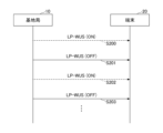
- the base station 10 transmits, when necessary, LP-WUS (OFF) to the terminal 20 instructing not to wake up the MR (to turn the power OFF) in LP-WUS occasions having a certain time period shown in FIG. 6(b). That is, when the terminal 20 does not receive LP-WUS (OFF) in a resource of a predetermined period, it assumes that there is an instruction to wake up. In addition, the base station 10 does not transmit LP-WUS (ON) to the terminal 20, which is an instruction to wake up the MR (to turn the power ON).
- the base station 10 may transmit a new signal such as Keep-Alive or an existing LP-WUS to confirm whether the terminal 20 is capable of communication, regardless of whether LP-WUS transmission is necessary.
- FIG. 16 is an example of a sequence diagram regarding a method of transmitting LP-WUS in the third embodiment of the present invention. The processing of each step will be described below.
- Step S200 When the base station 10 issues an instruction to wake up the MR at the timing of transmitting the LP-WUS at a predetermined cycle, the base station 10 does not transmit the LP-WUS(ON) to the terminal 20.
- Step S201 If the base station 10 does not instruct the MR to wake up at the timing of transmitting the LP-WUS at a predetermined period, it transmits LP-WUS(OFF) to the terminal 20.
- Step S202 As in step S200, when the base station 10 issues an instruction to wake up the MR at the timing of transmitting the LP-WUS at a predetermined period, the base station 10 does not transmit the LP-WUS(ON) to the terminal 20.
- Step S203 As in step S201, if the base station 10 does not instruct the terminal 20 to wake up the MR at the timing of transmitting the LP-WUS at a predetermined period, the base station 10 transmits LP-WUS(OFF) to the terminal 20.
- the base station 10 repeatedly executes the LP-WUS transmission process shown in steps S200 to S203 at the timing of transmitting the LP-WUS at a predetermined cycle. Also, if the terminal 20 does not receive the LP-WUS, as in steps S200 and S202, it executes the paging and RACH (random access channel) processes as shown in FIG. 14.
- the LP-WUS (OFF) that instructs not to wake up the MR shown in the embodiment 3 (to turn the power OFF) includes a terminal identifier (UE_ID) that indicates the terminal that is not to be woken up.
- UE_ID terminal identifier
- the LP-WUS (OFF) instructing not to wake up the MR shown in the embodiment 3 (turning the power OFF) may include a terminal group identifier (UE_group_ID) indicating a group of multiple terminals that are not to be woken up, and information indicating whether or not wakeup is not required may be notified for each terminal group.
- UE_group_ID terminal group identifier
- the base station 10 may send a notification, i.e., send LP-WUS(OFF) to the terminal 20, only when it is determined that all terminals in the terminal group do not need to wake up.
- the base station 10 may notify each terminal group of an individual LP-WUS, or may send notifications to all terminal groups in one LP-WUS. For example, if there are eight terminal groups, information indicating whether or not to notify each terminal group may be included in one LP-WUS using an 8-bit bitmap.
- Example 3-2 In the embodiment 3-2, as described in the embodiment 3, when only LP-WUS (OFF) is received from the base station 10, if the terminal 20 cannot determine whether it has not received LP-WUS and should wake up, or whether a reception error has occurred, the terminal 20 may execute the process of paging and RACH (random access channel) as shown in FIG.
- RACH random access channel
- the terminal 20 may determine that an LP-WUS reception error has occurred and send a NACK to the base station 10.
- the terminal 20 may determine that an LP-WUS reception error has occurred and send a NACK to the base station 10.
- the terminal 20 may determine that an LP-WUS reception error has occurred and send a NACK to the base station 10. This makes it possible to reduce the number of LP-WUS retransmissions compared to the case of sending only LP-WUS (ON) in the second embodiment.
- the base station 10 may stop transmitting the LP-WUS, and the terminal 20 may stop receiving the LP-WUS.
- the base station 10 may send a stop instruction to the terminal 20 to stop the operation of transmitting the LP-WUS.
- the base station 10 and the terminal 20 may update the configuration information regarding the LP-WUS described in Examples 1-3.
- the base station 10 may update the configuration information regarding the LP-WUS described in Examples 1-3 and transmit the updated configuration information to the terminal 20.
- the terminal 20 will not miss paging that it should monitor due to an LP-WUS reception error. This is because the terminal 20 executes paging processing (processing to monitor paging) when it detects an error in receiving LP-WUS (OFF). If LP-WUS (OFF) is received normally, the terminal 20 has not been paged, and if LP-WUS (OFF) is not received normally, the terminal 20 determines that it is a wake-up instruction and executes paging processing.
- paging processing processing to monitor paging
- the above-described embodiment allows the transmission method and retransmission method of LP-WUS to be specified in a wireless communication system.
- the name of LP-WUS may be, for example, low power wake-up signal.
- the base station 10 and the terminal 20 include functions for implementing the above-mentioned embodiments. However, the base station 10 and the terminal 20 may each include only a part of the functions in the embodiments.
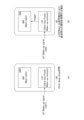
- Fig. 17 is a diagram showing an example of the functional configuration of the base station 10 in the embodiment of the present invention.
- the base station 10 has a transmitting unit 110, a receiving unit 120, a setting unit 130, and a control unit 140.
- the functional configuration shown in Fig. 17 is merely an example.
- the names of the functional divisions and functional units may be any as long as they can execute the operations related to the embodiment of the present invention.
- the transmitting unit 110 has a function of generating a signal to be transmitted to the terminal 20 and transmitting the signal wirelessly.
- the transmitting unit 110 also transmits an ultra-low power wake-up signal, and setting information, instructions, and notifications related to the ultra-low power wake-up signal, to the terminal 20.
- the transmitting unit 110 also transmits notifications related to switching of monitoring operations to the terminal.
- the receiving unit 120 has a function of receiving various signals transmitted from the terminal 20 and acquiring, for example, information of a higher layer from the received signals.
- the transmitting unit 110 also has a function of transmitting PSS, SSS, PBCH, DL/UL control signals, and the like to the terminal 20.
- the receiving unit 120 also receives inter-network node messages from other network nodes.
- the setting unit 130 stores preset setting information and various setting information to be transmitted to the terminal 20.
- the contents of the setting information include, for example, information related to settings related to paging notification information and low power wake-up signals.
- control unit 140 performs control related to the decision to switch the monitoring operation of the ultra-low power wakeup signal, the setting, instruction, and notification of the low power wakeup signal.
- the functional unit related to signal transmission in the control unit 140 may be included in the transmitting unit 110, and the functional unit related to signal reception in the control unit 140 may be included in the receiving unit 120.
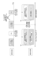
- Fig. 18 is a diagram showing an example of a functional configuration of the terminal 20 in the embodiment of the present invention.
- the terminal 20 has a transmitting unit 210, a receiving unit 220, a setting unit 230, and a control unit 240.
- the functional configuration shown in Fig. 18 is merely an example. As long as the operation related to the embodiment of the present invention can be executed, the names of the functional divisions and the functional units may be any.
- the transmitting unit 210 and the receiving unit 220 may be collectively referred to as a communication unit.
- the transmitting unit 210 creates a transmission signal from the transmission data and transmits the transmission signal wirelessly.
- the transmitting unit 210 also transmits a success response or failure response regarding the transmission of the ultra-low power wake-up signal to the base station 10.
- the receiving unit 220 wirelessly receives various signals and acquires higher layer signals from the received physical layer signals.
- the receiving unit 220 also has a function of receiving PSS, SSS, PBCH, DL/UL/SL control signals, etc. transmitted from the base station 10.
- the receiving unit 220 also receives paging notification information and setting information, instructions, notifications, etc. related to the low power wake-up signal from the base station 10.
- the receiving unit 220 receives an ultra-low power wake-up signal from the base station 10.
- the setting unit 230 stores various setting information received from the base station 10 by the receiving unit 220.
- the setting unit 230 also stores setting information that is set in advance.
- the configuration information includes, for example, information related to settings for paging notification information and low power
- the control unit 240 performs settings related to the ultra-low power wake-up signal as described in the embodiment.
- the functional unit related to signal transmission in the control unit 240 may be included in the transmitting unit 210, and the functional unit related to signal reception in the control unit 240 may be included in the receiving unit 220.
- each functional block may be realized using one device that is physically or logically coupled, or may be realized using two or more devices that are physically or logically separated and directly or indirectly connected (for example, using wires, wirelessly, etc.) and these multiple devices.
- the functional block may be realized by combining the one device or the multiple devices with software.
- Functions include, but are not limited to, judgement, determination, judgment, calculation, computation, processing, derivation, investigation, search, confirmation, reception, transmission, output, access, resolution, selection, selection, establishment, comparison, assumption, expectation, regarding, broadcasting, notifying, communicating, forwarding, configuring, reconfiguring, allocating, mapping, and assignment.
- a functional block (component) that performs the transmission function is called a transmitting unit or transmitter.
- the base station 10, terminal 20, etc. in one embodiment of the present disclosure may function as a computer that performs processing of the wireless communication method of the present disclosure.
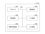
- FIG. 19 is a diagram showing an example of the hardware configuration of the base station 10 and terminal 20 in one embodiment of the present disclosure.
- the above-mentioned base station 10 and terminal 20 may be physically configured as a computer device including a processor 1001, a storage device 1002, an auxiliary storage device 1003, a communication device 1004, an input device 1005, an output device 1006, a bus 1007, etc.
- the term "apparatus" can be interpreted as a circuit, device, unit, etc.
- the hardware configuration of the base station 10 and the terminal 20 may be configured to include one or more of the devices shown in the figure, or may be configured to exclude some of the devices.
- the functions of the base station 10 and the terminal 20 are realized by loading specific software (programs) onto hardware such as the processor 1001 and the storage device 1002, causing the processor 1001 to perform calculations, control communications by the communication device 1004, and control at least one of the reading and writing of data in the storage device 1002 and the auxiliary storage device 1003.
- the processor 1001 for example, operates an operating system to control the entire computer.
- the processor 1001 may be configured as a central processing unit (CPU) including an interface with peripheral devices, a control device, an arithmetic unit, registers, etc.
- CPU central processing unit
- control unit 140, control unit 240, etc. may be realized by the processor 1001.
- the processor 1001 reads out a program (program code), software module, data, etc. from at least one of the auxiliary storage device 1003 and the communication device 1004 to the storage device 1002, and executes various processes according to the program.
- the program is a program that causes a computer to execute at least a part of the operations described in the above-mentioned embodiment.
- the control unit 140 of the base station 10 shown in FIG. 17 may be stored in the storage device 1002 and realized by a control program that runs on the processor 1001.
- the control unit 240 of the terminal 20 shown in FIG. 18 may be stored in the storage device 1002 and realized by a control program that runs on the processor 1001.
- the processor 1001 may be implemented by one or more chips.
- the program may be transmitted from a network via a telecommunication line.
- the storage device 1002 is a computer-readable recording medium and may be composed of, for example, at least one of a ROM (Read Only Memory), an EPROM (Erasable Programmable ROM), an EEPROM (Electrically Erasable Programmable ROM), a RAM (Random Access Memory), etc.
- the storage device 1002 may also be called a register, a cache, a main memory, etc.
- the storage device 1002 can store executable programs (program codes), software modules, etc. for implementing a communication method relating to one embodiment of the present disclosure.
- the auxiliary storage device 1003 is a computer-readable recording medium, and may be, for example, at least one of an optical disk such as a CD-ROM (Compact Disc ROM), a hard disk drive, a flexible disk, a magneto-optical disk (e.g., a compact disk, a digital versatile disk, a Blu-ray (registered trademark) disk), a smart card, a flash memory (e.g., a card, a stick, a key drive), a floppy (registered trademark) disk, a magnetic strip, etc.
- the above-mentioned storage medium may be, for example, a database, a server, or other suitable medium that includes at least one of the storage device 1002 and the auxiliary storage device 1003.
- the communication device 1004 is hardware (transmitting/receiving device) for communicating between computers via at least one of a wired network and a wireless network, and is also referred to as, for example, a network device, a network controller, a network card, a communication module, etc.
- the communication device 1004 may be configured to include a high-frequency switch, a duplexer, a filter, a frequency synthesizer, etc., to realize at least one of, for example, Frequency Division Duplex (FDD) and Time Division Duplex (TDD).
- FDD Frequency Division Duplex
- TDD Time Division Duplex
- the transmitting/receiving antenna, an amplifier unit, a transmitting/receiving unit, a transmission path interface, etc. may be realized by the communication device 1004.
- the transmitting/receiving unit may be implemented as a transmitting unit or a receiving unit that is physically or logically separated.
- the input device 1005 is an input device (e.g., a keyboard, a mouse, a microphone, a switch, a button, a sensor, etc.) that accepts input from the outside.
- the output device 1006 is an output device (e.g., a display, a speaker, an LED lamp, etc.) that outputs to the outside. Note that the input device 1005 and the output device 1006 may be integrated into one structure (e.g., a touch panel).
- each device such as the processor 1001 and the storage device 1002 is connected by a bus 1007 for communicating information.
- the bus 1007 may be configured using a single bus, or may be configured using different buses between each device.
- the base station 10 and the terminal 20 may be configured to include hardware such as a microprocessor, a digital signal processor (DSP), an application specific integrated circuit (ASIC), a programmable logic device (PLD), or a field programmable gate array (FPGA), and some or all of the functional blocks may be realized by the hardware.
- the processor 1001 may be implemented using at least one of these pieces of hardware.
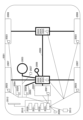
- FIG. 20 shows an example configuration of a vehicle 2001.
- the vehicle 2001 includes a drive unit 2002, a steering unit 2003, an accelerator pedal 2004, a brake pedal 2005, a shift lever 2006, front wheels 2007, rear wheels 2008, an axle 2009, an electronic control unit 2010, various sensors 2021-2029, an information service unit 2012, and a communication module 2013.
- a communication device mounted on the vehicle 2001 may be applied to the communication module 2013, for example.
- the drive unit 2002 is composed of, for example, an engine, a motor, or a hybrid of an engine and a motor.
- the steering unit 2003 includes at least a steering wheel (also called a handlebar), and is configured to steer at least one of the front wheels and the rear wheels based on the operation of the steering wheel operated by the user.
- the electronic control unit 2010 is composed of a microprocessor 2031, memory (ROM, RAM) 2032, and a communication port (IO port) 2033. Signals are input to the electronic control unit 2010 from various sensors 2021 to 2029 provided in the vehicle 2001.
- the electronic control unit 2010 may also be called an ECU (Electronic Control Unit).
- Signals from the various sensors 2021-2029 include a current signal from a current sensor 2021 that senses the motor current, a front or rear wheel rotation speed signal acquired by a rotation speed sensor 2022, a front or rear wheel air pressure signal acquired by an air pressure sensor 2023, a vehicle speed signal acquired by a vehicle speed sensor 2024, an acceleration signal acquired by an acceleration sensor 2025, an accelerator pedal depression amount signal acquired by an accelerator pedal sensor 2029, a brake pedal depression amount signal acquired by a brake pedal sensor 2026, a shift lever operation signal acquired by a shift lever sensor 2027, and a detection signal for detecting obstacles, vehicles, pedestrians, etc. acquired by an object detection sensor 2028.
- the information service unit 2012 is composed of various devices, such as a car navigation system, an audio system, speakers, a television, and a radio, for providing (outputting) various information such as driving information, traffic information, and entertainment information, and one or more ECUs for controlling these devices.
- the information service unit 2012 uses information acquired from an external device via the communication module 2013 or the like to provide various multimedia information and multimedia services to the occupants of the vehicle 2001.
- the information service unit 2012 may include input devices (e.g., a keyboard, a mouse, a microphone, a switch, a button, a sensor, a touch panel, etc.) that accept input from the outside, and may also include output devices (e.g., a display, a speaker, an LED lamp, a touch panel, etc.) that perform output to the outside.
- input devices e.g., a keyboard, a mouse, a microphone, a switch, a button, a sensor, a touch panel, etc.
- output devices e.g., a display, a speaker, an LED lamp, a touch panel, etc.
- the driving assistance system unit 2030 is composed of various devices that provide functions for preventing accidents and reducing the driving burden on the driver, such as a millimeter wave radar, LiDAR (Light Detection and Ranging), a camera, a positioning locator (e.g., GNSS, etc.), map information (e.g., high definition (HD) maps, autonomous vehicle (AV) maps, etc.), a gyro system (e.g., IMU (Inertial Measurement Unit), INS (Inertial Navigation System), etc.), AI (Artificial Intelligence) chip, and an AI processor, as well as one or more ECUs that control these devices.
- the driving assistance system unit 2030 transmits and receives various information via the communication module 2013 to realize driving assistance functions or autonomous driving functions.
- the communication module 2013 can communicate with the microprocessor 2031 and components of the vehicle 2001 via the communication port.
- the communication module 2013 transmits and receives data via the communication port 2033 between the drive unit 2002, steering unit 2003, accelerator pedal 2004, brake pedal 2005, shift lever 2006, front wheels 2007, rear wheels 2008, axle 2009, microprocessor 2031 and memory (ROM, RAM) 2032 in the electronic control unit 2010, and sensors 2021 to 29, which are provided in the vehicle 2001.
- the communication module 2013 is a communication device that can be controlled by the microprocessor 2031 of the electronic control unit 2010 and can communicate with an external device. For example, it transmits and receives various information to and from the external device via wireless communication.
- the communication module 2013 may be located either inside or outside the electronic control unit 2010.
- the external device may be, for example, a base station, a mobile station, etc.
- the communication module 2013 may transmit at least one of the signals from the various sensors 2021-2028 described above input to the electronic control unit 2010, information obtained based on the signals, and information based on input from the outside (user) obtained via the information service unit 2012 to an external device via wireless communication.
- the electronic control unit 2010, the various sensors 2021-2028, the information service unit 2012, etc. may be referred to as input units that accept input.
- the PUSCH transmitted by the communication module 2013 may include information based on the above input.
- the communication module 2013 receives various information (traffic information, signal information, vehicle distance information, etc.) transmitted from an external device, and displays it on the information service unit 2012 provided in the vehicle 2001.
- the information service unit 2012 may be called an output unit that outputs information (for example, outputs information to a device such as a display or speaker based on the PDSCH (or data/information decoded from the PDSCH) received by the communication module 2013).
- the communication module 2013 also stores various information received from an external device in a memory 2032 that can be used by the microprocessor 2031.
- the microprocessor 2031 may control the drive unit 2002, steering unit 2003, accelerator pedal 2004, brake pedal 2005, shift lever 2006, front wheels 2007, rear wheels 2008, axles 2009, sensors 2021 to 2029, etc. provided in the vehicle 2001.
- a receiver that receives an ultra-low power wakeup signal including an instruction not to wake up, which is transmitted as necessary, from a base station in a resource of a predetermined period; a control unit that assumes that a wakeup instruction is given when the resource does not receive the ultra-low power wakeup signal; A terminal having the above configuration.
- the control unit executes a paging process between the base station and the control unit when the reception of the ultra-low power wake-up signal is unsuccessful, a transmission unit that transmits a failure response indicating a failure in receiving the ultra-low power wakeup signal to the base station if the terminal itself is not paged when the paging process is executed; 2.
- the terminal of claim 1 further comprising: (Section 3) The control unit executes a paging process between the base station and the control unit when the reception of the ultra-low power wake-up signal is unsuccessful, a transmission unit that transmits a stop request indicating that the terminal is to stop receiving the ultra-low power wakeup signal to the base station when the terminal is not paged a predetermined number of times or more consecutively during the paging process; 2.
- the terminal of claim 1 further comprising: (Section 4) The terminal according to claim 1, wherein the ultra-low power wake-up signal includes an identifier of a terminal or an identifier of a group of terminals that are the subject of an instruction not to wake up.
- a transmitter that transmits an ultra-low power wakeup signal including an instruction not to wake up to a terminal, the ultra-low power wakeup signal being transmitted as necessary, to the terminal in a resource of a predetermined period; a receiving unit that receives from the terminal a failure response indicating a failure in receiving the ultra-low power wakeup signal or a stop request requesting a stop of transmission of the ultra-low power wakeup signal; a control unit that stops transmission of the ultra-low power wakeup signal based on the failure response or the stop request; A base station having (Section 6) receiving an ultra-low power wake-up signal from a base station on a resource of a predetermined period, the wake-up signal including an instruction not to wake up, the wake-up signal being transmitted as needed; assuming a wake-up indication in the resource if the ultra-low power wake-up signal is not received; A communication method for a terminal having the above configuration.
- the operations of multiple functional units may be physically performed by one part, or the operations of one functional unit may be physically performed by multiple parts.
- the order of the processing procedures described in the embodiment may be changed as long as there is no contradiction.
- the base station 10 and the terminal 20 have been described using functional block diagrams, but such devices may be realized by hardware, software, or a combination thereof.
- the software operated by the processor possessed by the base station 10 in accordance with an embodiment of the present invention and the software operated by the processor possessed by the terminal 20 in accordance with an embodiment of the present invention may each be stored in random access memory (RAM), flash memory, read only memory (ROM), EPROM, EEPROM, register, hard disk (HDD), removable disk, CD-ROM, database, server or any other suitable storage medium.
- the notification of information is not limited to the aspects/embodiments described in the present disclosure and may be performed using other methods.
- the notification of information may be performed by physical layer signaling (e.g., Downlink Control Information (DCI), Uplink Control Information (UCI)), higher layer signaling (e.g., Radio Resource Control (RRC) signaling, Medium Access Control (MAC) signaling), broadcast information (Master Information Block (MIB), System Information Block (SIB)), other signals, or a combination of these.
- RRC signaling may be referred to as an RRC message, and may be, for example, an RRC Connection Setup message, an RRC Connection Reconfiguration message, etc.
- Each aspect/embodiment described in this disclosure may be applied to at least one of systems utilizing LTE (Long Term Evolution), LTE-Advanced (LTE-A), SUPER 3G, IMT-Advanced, 4G (4th generation mobile communication system), 5G (5th generation mobile communication system), FRA (Future Radio Access), NR (new Radio), W-CDMA (registered trademark), GSM (registered trademark), CDMA2000, UMB (Ultra Mobile Broadband), IEEE 802.11 (Wi-Fi (registered trademark)), IEEE 802.16 (WiMAX (registered trademark)), IEEE 802.20, UWB (Ultra-Wide Band), Bluetooth (registered trademark), or other suitable systems, and next generation systems enhanced based on these. Additionally, multiple systems may be combined (for example, a combination of at least one of LTE and LTE-A with 5G, etc.).
- certain operations that are described as being performed by the base station 10 may in some cases be performed by its upper node.
- various operations performed for communication with a terminal 20 may be performed by at least one of the base station 10 and other network nodes other than the base station 10 (such as, but not limited to, an MME or S-GW).
- the base station 10 may be a combination of multiple other network nodes (such as an MME and an S-GW).
- the information or signals described in this disclosure may be output from a higher layer (or a lower layer) to a lower layer (or a higher layer). They may be input and output via multiple network nodes.
- the input and output information may be stored in a specific location (e.g., memory) or may be managed using a management table.
- the input and output information may be overwritten, updated, or added to.
- the output information may be deleted.
- the input information may be sent to another device.
- the determination in this disclosure may be based on a value represented by one bit (0 or 1), a Boolean (true or false) value, or a comparison of numerical values (e.g., a comparison with a predetermined value).
- Software shall be construed broadly to mean instructions, instruction sets, code, code segments, program code, programs, subprograms, software modules, applications, software applications, software packages, routines, subroutines, objects, executable files, threads of execution, procedures, functions, etc., whether referred to as software, firmware, middleware, microcode, hardware description language, or otherwise.
- Software, instructions, information, etc. may also be transmitted and received via a transmission medium.
- a transmission medium For example, if the software is transmitted from a website, server, or other remote source using at least one of wired technologies (such as coaxial cable, fiber optic cable, twisted pair, Digital Subscriber Line (DSL)), and/or wireless technologies (such as infrared, microwave), then at least one of these wired and wireless technologies is included within the definition of a transmission medium.
- wired technologies such as coaxial cable, fiber optic cable, twisted pair, Digital Subscriber Line (DSL)
- wireless technologies such as infrared, microwave
- the information, signals, etc. described in this disclosure may be represented using any of a variety of different technologies.
- the data, instructions, commands, information, signals, bits, symbols, chips, etc. that may be referred to throughout the above description may be represented by voltages, currents, electromagnetic waves, magnetic fields or magnetic particles, optical fields or photons, or any combination thereof.
- the channel and the symbol may be a signal (signaling).
- the signal may be a message.
- the component carrier (CC) may be called a carrier frequency, a cell, a frequency carrier, etc.
- system and “network” are used interchangeably.
- a radio resource may be indicated by an index.
- the names used for the parameters described above are not intended to be limiting in any way. Furthermore, the formulas etc. using these parameters may differ from those explicitly disclosed in this disclosure.
- the various channels (e.g., PUCCH, PDCCH, etc.) and information elements may be identified by any suitable names, and therefore the various names assigned to these various channels and information elements are not intended to be limiting in any way.
- base station BS
- wireless base station base station
- base station device fixed station
- NodeB nodeB
- eNodeB eNodeB
- gNodeB gNodeB
- access point e.g., "transmission point”
- gNodeB gNodeB
- a base station may also be referred to by terms such as macrocell, small cell, femtocell, and picocell.
- a base station can accommodate one or more (e.g., three) cells.
- a base station accommodates multiple cells, the entire coverage area of the base station can be divided into multiple smaller areas, and each smaller area can also provide communication services by a base station subsystem (e.g., a small indoor base station (RRH: Remote Radio Head)).
- RRH Remote Radio Head
- the term "cell” or “sector” refers to a part or the entire coverage area of at least one of the base station and base station subsystems that provide communication services in this coverage.
- a base station transmitting information to a terminal may be interpreted as the base station instructing the terminal to control or operate based on the information.
- MS Mobile Station
- UE User Equipment
- a mobile station may also be referred to by those skilled in the art as a subscriber station, mobile unit, subscriber unit, wireless unit, remote unit, mobile device, wireless device, wireless communication device, remote device, mobile subscriber station, access terminal, mobile terminal, wireless terminal, remote terminal, handset, user agent, mobile client, client, or some other suitable terminology.
- At least one of the base station and the mobile station may be called a transmitting device, a receiving device, a communication device, etc.
- At least one of the base station and the mobile station may be a device mounted on a moving object, the moving object itself, etc.
- the moving object is a movable object, and the moving speed is arbitrary. It also includes the case where the moving object is stopped.
- the moving object includes, but is not limited to, for example, a vehicle, a transport vehicle, an automobile, a motorcycle, a bicycle, a connected car, an excavator, a bulldozer, a wheel loader, a dump truck, a forklift, a train, a bus, a handcar, a rickshaw, a ship and other watercraft, an airplane, a rocket, an artificial satellite, a drone (registered trademark), a multicopter, a quadcopter, a balloon, and objects mounted thereon.
- the moving object may also be a moving object that travels autonomously based on an operation command.
- At least one of the base station and the mobile station may be a device that does not necessarily move during communication operations.
- at least one of the base station and the mobile station may be an IoT (Internet of Things) device such as a sensor.
- IoT Internet of Things
- the base station in the present disclosure may be read as a user terminal.
- each aspect/embodiment of the present disclosure may be applied to a configuration in which communication between a base station and a user terminal is replaced with communication between multiple terminals 20 (which may be called, for example, D2D (Device-to-Device) or V2X (Vehicle-to-Everything)).
- the terminal 20 may be configured to have the functions of the base station 10 described above.
- terms such as "uplink” and "downlink” may be read as terms corresponding to terminal-to-terminal communication (for example, "side").
- the uplink channel, downlink channel, etc. may be read as a side channel.
- the user terminal in this disclosure may be interpreted as a base station.
- the base station may be configured to have the functions of the user terminal described above.
- determining may encompass a wide variety of actions.
- Determining and “determining” may include, for example, judging, calculating, computing, processing, deriving, investigating, looking up, search, inquiry (e.g., searching in a table, database, or other data structure), and considering ascertaining as “judging” or “determining.”
- determining and “determining” may include receiving (e.g., receiving information), transmitting (e.g., sending information), input, output, accessing (e.g., accessing data in memory), and considering ascertaining as “judging” or “determining.”
- judgment” and “decision” can include considering resolving, selecting, choosing, establishing, comparing, etc., to have been “judged” or “decided.” In other words, “judgment” and “decision” can include considering some action to have been “judged” or “decided.” Additionally, “judgment (decision)” can be interpreted as “assuming,” “ex
- connection refers to any direct or indirect connection or coupling between two or more elements, and may include the presence of one or more intermediate elements between two elements that are “connected” or “coupled” to each other.
- the coupling or connection between elements may be physical, logical, or a combination thereof.
- “connected” may be read as "access.”
- two elements may be considered to be “connected” or “coupled” to each other using at least one of one or more wires, cables, and printed electrical connections, as well as electromagnetic energy having wavelengths in the radio frequency range, microwave range, and optical (both visible and invisible) range, as some non-limiting and non-exhaustive examples.
- the reference signal may also be abbreviated as RS (Reference Signal) or may be called a pilot depending on the applicable standard.
- the phrase “based on” does not mean “based only on,” unless expressly stated otherwise. In other words, the phrase “based on” means both “based only on” and “based at least on.”
- any reference to an element using a designation such as "first,” “second,” etc., used in this disclosure does not generally limit the quantity or order of those elements. These designations may be used in this disclosure as a convenient method of distinguishing between two or more elements. Thus, a reference to a first and a second element does not imply that only two elements may be employed or that the first element must precede the second element in some way.
- a radio frame may be composed of one or more frames in the time domain. Each of the one or more frames in the time domain may be called a subframe. A subframe may further be composed of one or more slots in the time domain. A subframe may have a fixed time length (e.g., 1 ms) that is independent of numerology.
- Numerology may be a communication parameter that applies to at least one of the transmission and reception of a signal or channel. Numerology may indicate, for example, at least one of the following: subcarrier spacing (SCS), bandwidth, symbol length, cyclic prefix length, transmission time interval (TTI), number of symbols per TTI, radio frame structure, a specific filtering process performed by the transceiver in the frequency domain, a specific windowing process performed by the transceiver in the time domain, etc.
- SCS subcarrier spacing
- TTI transmission time interval
- radio frame structure a specific filtering process performed by the transceiver in the frequency domain
- a specific windowing process performed by the transceiver in the time domain etc.
- a slot may consist of one or more symbols in the time domain (such as OFDM (Orthogonal Frequency Division Multiplexing) symbols, SC-FDMA (Single Carrier Frequency Division Multiple Access) symbols, etc.).
- a slot may be a time unit based on numerology.
- a slot may include multiple minislots. Each minislot may consist of one or multiple symbols in the time domain. A minislot may also be called a subslot. A minislot may consist of fewer symbols than a slot.
- a PDSCH (or PUSCH) transmitted in a time unit larger than a minislot may be called PDSCH (or PUSCH) mapping type A.
- a PDSCH (or PUSCH) transmitted using a minislot may be called PDSCH (or PUSCH) mapping type B.
- Radio frame, subframe, slot, minislot, and symbol all represent time units for transmitting signals. Radio frame, subframe, slot, minislot, and symbol may each be referred to by a different name that corresponds to the radio frame, subframe, slot, minislot, and symbol.
- one subframe may be called a Transmission Time Interval (TTI)
- TTI Transmission Time Interval
- multiple consecutive subframes may be called a TTI
- one slot or one minislot may be called a TTI.
- at least one of the subframe and the TTI may be a subframe (1 ms) in existing LTE, a period shorter than 1 ms (e.g., 1-13 symbols), or a period longer than 1 ms.
- the unit representing the TTI may be called a slot, minislot, etc., instead of a subframe.
- TTI refers to, for example, the smallest time unit for scheduling in wireless communication.
- a base station performs scheduling to allocate wireless resources (such as frequency bandwidth and transmission power that can be used by each terminal 20) to each terminal 20 in TTI units.
- wireless resources such as frequency bandwidth and transmission power that can be used by each terminal 20
- TTI is not limited to this.
- the TTI may be a transmission time unit for a channel-coded data packet (transport block), a code block, a code word, etc., or may be a processing unit for scheduling, link adaptation, etc.
- the time interval e.g., the number of symbols
- the time interval in which a transport block, a code block, a code word, etc. is actually mapped may be shorter than the TTI.
- one or more TTIs may be the minimum time unit of scheduling.
- the number of slots (minislots) that constitute the minimum time unit of scheduling may be controlled.
- a TTI having a time length of 1 ms may be called a normal TTI (TTI in LTE Rel. 8-12), normal TTI, long TTI, normal subframe, normal subframe, long subframe, slot, etc.
- TTI shorter than a normal TTI may be called a shortened TTI, short TTI, partial or fractional TTI, shortened subframe, short subframe, minislot, subslot, slot, etc.
- a long TTI (e.g., a normal TTI, a subframe, etc.) may be interpreted as a TTI having a time length of more than 1 ms
- a short TTI e.g., a shortened TTI, etc.
- TTI length shorter than the TTI length of a long TTI and equal to or greater than 1 ms.
- a resource block is a resource allocation unit in the time domain and frequency domain, and may include one or more consecutive subcarriers in the frequency domain.
- the number of subcarriers included in an RB may be the same regardless of the numerology, and may be, for example, 12.
- the number of subcarriers included in an RB may be determined based on the numerology.
- the time domain of an RB may include one or more symbols and may be one slot, one minislot, one subframe, or one TTI in length.
- One TTI, one subframe, etc. may each be composed of one or more resource blocks.
- one or more RBs may be referred to as a physical resource block (PRB), a sub-carrier group (SCG), a resource element group (REG), a PRB pair, an RB pair, etc.
- PRB physical resource block
- SCG sub-carrier group
- REG resource element group
- PRB pair an RB pair, etc.
- a resource block may be composed of one or more resource elements (REs).
- REs resource elements
- one RE may be a radio resource area of one subcarrier and one symbol.
- a bandwidth part which may also be referred to as a partial bandwidth, may represent a subset of contiguous common resource blocks (RBs) for a given numerology on a given carrier, where the common RBs may be identified by an index of the RB relative to a common reference point of the carrier.
- PRBs may be defined in a BWP and numbered within the BWP.
- the BWP may include a BWP for UL (UL BWP) and a BWP for DL (DL BWP).
- UL BWP UL BWP
- DL BWP DL BWP
- One or more BWPs may be configured for a UE within one carrier.
- At least one of the configured BWPs may be active, and the UE may not expect to transmit or receive a given signal/channel outside the active BWP.
- BWP bitmap
- radio frames, subframes, slots, minislots, and symbols are merely examples.
- the number of subframes included in a radio frame, the number of slots per subframe or radio frame, the number of minislots included in a slot, the number of symbols and RBs included in a slot or minislot, the number of subcarriers included in an RB, as well as the number of symbols in a TTI, the symbol length, and the cyclic prefix (CP) length can be changed in various ways.
- a and B are different may mean “A and B are different from each other.”
- the term may also mean “A and B are each different from C.”
- Terms such as “separate” and “combined” may also be interpreted in the same way as “different.”
- notification of specific information is not limited to being done explicitly, but may be done implicitly (e.g., not notifying the specific information).
- Base station 110 Transmitter 120 Receiver 130 Setting unit 140 Control unit 20 Terminal 210 Transmitter 220 Receiver 230 Setting unit 240 Control unit 1001 Processor 1002 Storage device 1003 Auxiliary storage device 1004 Communication device 1005 Input device 1006 Output device 2001 Vehicle 2002 Drive unit 2003 Steering unit 2004 Accelerator pedal 2005 Brake pedal 2006 Shift lever 2007 Front wheel 2008 Rear wheel 2009 Axle 2010 Electronic control unit 2012 Information service unit 2013 Communication module 2021 Current sensor 2022 Rotational speed sensor 2023 Air pressure sensor 2024 Vehicle speed sensor 2025 Acceleration sensor 2026 Brake pedal sensor 2027 Shift lever sensor 2028 Object detection sensor 2029 Accelerator pedal sensor 2030 Driving assistance system unit 2031 Microprocessor 2032 Memory (ROM, RAM) 2033 Communication port (IO port)
Landscapes
- Mobile Radio Communication Systems (AREA)
Abstract
Description
第1の実施形態について説明する。図5は、本発明の実施の形態におけるLP-WUSの送信方法を説明するための図である。図5では、基地局10は、LP-WUSが送信可能なリソースの範囲に関する情報を含む設定情報を設定し、設定情報に基づいて、設定したリソース範囲内において必要なタイミングでLP-WUSを端末20に送信する。端末20は、基地局10から受信したLP-WUSが送信可能なリソースの範囲に関する情報を含む設定情報に基づいて、LP-WUSを受信するためのリソースなどを設定し、基地局10から送信されたLP-WUSを受信する。図5において送信されるLP-WUSは、例えば、MRをWake-up(ウエイクアップ)させる(電源ONにする)ことを指示する信号である。
(実施例1)
実施例1について説明する。実施例1では、図6(a)に示したように、基地局10は、一定の時間的な周期をもつLP-WUS occasions における全ての機会において、MRをWake-upする指示又はWake-upさせない指示をするLP-WUS (LP-WUS(ON)又はLP-WUS(OFF))を端末20に送信する。また、端末20は、基地局10に対して、LP-WUSの受信が成功(ACK、成功応答)又は不成功(NACK、失敗応答)のいずれかを通知してもよい。図8は、本発明の実施例1におけるLP-WUSの送信方法に関するシーケンス図の一例である。本シーケンスは、受信側で誤りが発生しない場合である。以下、各ステップの処理について説明する。
実施例1-1aについて説明する。実施例1-1aにおいて、受信側で誤りが発生した場合のLP-WUSの再送方法の一例を示す。受信側で誤りが発生した場合とは、例えば、何等かの信号を受信したが、誤り検出処理によって誤りが検出されているため、正しく信号を受信できなかった場合である。受信側で誤りが発生した場合を、受信できなかった場合、又は、受信に失敗した場合などとよぶ場合もある。端末20は、予め定めた周期のタイミングにおいて、LP-WUSを受信できなかった場合に、基地局10にNACKを送信することで、LP-WUSの再送を指示する。基地局10は、予め定められた再送用のリソースを用いてLP-WUSを端末20に再送する。図9は、本発明の実施例1-1aにおけるLP-WUSの送信方法に関するシーケンス図の一例である。以下、各ステップの処理について説明する。
実施例1-1bについて説明する。実施例1-1bにおいて、受信側で誤りが発生した場合のLP-WUSの再送方法の一例を示す。端末20は、予め定めた周期のタイミングにおいて、LP-WUSを受信できなかった場合に、基地局10にNACKを送信することで、LP-WUSの再送を指示する。基地局10は、次に送信するLP-WUSにおいて、前回受信が失敗したLP-WUSを多重化したLP-WUSを端末20に送信する。図10は、本発明の実施例1-1bにおけるLP-WUSの送信方法に関するシーケンス図の一例である。以下、各ステップの処理について説明する。
実施例1-1cについて説明する。実施例1-1cにおいて、受信側で誤りが発生した場合のLP-WUSの再送方法の一例を示す。端末20は、予め定めた周期のタイミングにおいて、LP-WUSを受信できなかった場合に、基地局10にNACKを送信することで、LP-WUSの再送を指示する。基地局10は、再送するLP-WUSのリソースを指示する情報を含む再送指示を端末20に送信した後、指示したリソースを用いてLP-WUSを端末20に再送する。図11は、本発明の実施例1-1cにおけるLP-WUSの送信方法に関するシーケンス図の一例である。以下、各ステップの処理について説明する。
実施例1-2について説明する。実施例1-2において、受信側で誤りが発生した場合のLP-WUSの再送方法の一例を示す。端末20は、予め定めた周期のタイミングにおいて、LP-WUSを受信できなかった場合に、基地局10にNACKを送信することで、LP-WUSの再送を指示する。基地局10は、受信したNACKに基づいて、LP-WUSの送信を停止する停止指示を端末20に送信する。LP-WUSの送信を停止する期間は、予め定められた期間であってもよいし、停止指示に停止する期間に関する情報が含まれていてもよい。あるいは、端末20がLP-WUSの送信の再開を要求する再開要求を基地局10に送信することにより、LP-WUSの送信を再開してもよい。図12は、本発明の実施例1-2におけるLP-WUSの送信方法に関するシーケンス図の一例である。以下、各ステップの処理について説明する。
実施例1-3について説明する。実施例1-3において、基地局10は、LP-WUSに関する設定情報(configuration)を更新する指示を端末20に送信する。図13は、本発明の実施例1-3におけるLP-WUSの送信方法に関するシーケンス図の一例である。ステップS80において、基地局10は、LP-WUSに関する設定情報を更新する指示を端末20に送信する。ここで、設定情報は、例えば、LP-WUSの送信強度(送信電力)、送信周期、フォーマット、及びペイロードのサイズ等に関するパラメータを含み、基地局10は、これらのパラメータの値を更新した設定情報を端末20に送信する。また、基地局10は、端末20から受信するACK及びNACKに応じて受信状況を推定し、設定情報のパラメータの値を更新してもよい。例えば、基地局10は、ACKを多く受信するならば、受信状況が良いと推定して送信強度を上げる、NACKを多く受信するならば受信状況が悪いと推定して送信強度を下げるなどの調整を行う。
実施例1-4について説明する。実施例1-4において、端末20は、LP-WUSを受信したか否かを示すACK/NACKの指示を、既存の信号及びチャネル(PDCCH又はPUCCH等)に基づいて実行してもよいし、新規に導入した信号及びチャネルを用いて実行してもよい。ここで、端末20がこれらの信号の送信するために、端末20において、LP-WUSを受信するWUR (Wake UP Receiver)がMR (Main Radio)を起動してもよく、その結果、WURがOFFとなってよいし、WURによるLP-WUSのモニタリングが停止されてもよい。
実施例2について説明する。実施例2では、基地局10は、図6(b)に示した一定の時間的な周期をもつLP-WUS occasions において、必要な場合に、MRをWake-upさせる(電源ONにする)ことを指示するLP-WUS (ON)を端末20に送信する。即ち、基地局10は、MRをWake-upさせない(電源OFFにする)ことを指示であるLP-WUS (OFF)は端末20に送信しない。また、基地局10は、LP-WUS送信の必要の有無に関わらず、端末20が通信可能であるかを確認するために、Keep-Aliveなどの新規の信号、又は既存のLP-WUSを送信してもよい。図15は、本発明の実施例2におけるLP-WUSの送信方法に関するシーケンス図の一例である。以下、各ステップの処理について説明する。
実施例3について説明する。実施例3では、基地局10は、図6(b)に示した一定の時間的な周期をもつLP-WUS occasions において、必要な場合に、MRをWake-upさせない(電源OFFにする)ことを指示するLP-WUS (OFF)を端末20に送信する。即ち、端末20は、予め定められた周期のリソースにおいて、LP-WUS (OFF)を受信しない場合、ウエイクアップの指示があることを想定する。また、基地局10は、MRをWake-upさせる(電源ONにする)ことを指示であるLP-WUS (ON)を端末20に送信しない。また、基地局10は、LP-WUS送信の必要の有無に関わらず、端末20が通信可能であるかを確認するために、Keep-Aliveなどの新規の信号、又は既存のLP-WUSを送信してもよい。図16は、本発明の実施例3におけるLP-WUSの送信方法に関するシーケンス図の一例である。以下、各ステップの処理について説明する。
実施例3-1aについて説明する。実施例3-1aでは、実施例3で示したMRをWake-upさせない(電源OFFにする)ことを指示するLP-WUS (OFF)に、Wake-upさせない端末を示す端末識別子(UE_ID)を含める。
実施例3-1bについて説明する。実施例3-1bでは、実施例3で示したMRをWake-upさせない(電源OFFにする)ことを指示するLP-WUS (OFF)に、Wake-upさせない複数の端末のグループを示す端末グループ識別子(UE_group_ID)を含め、端末グループごとに、Wake-upをしなくてよいか否かを示す情報を通知してもよい。
実施例3-2について説明する。実施例3-2では、実施例3で説明した様に、基地局10からLP-WUS (OFF)のみを受信する場合において、端末20は、LP-WUSを受信しておらずWake-upすべきなのか、又は受信エラーが発生してるのか判断がつかない場合、図14に示したようにPaging(ページング)及びRACH(ランダムアクセスチャネル)の処理を実行してもよい。
次に、これまでに説明した処理及び動作を実行する基地局10及び端末20の機能構成例を説明する。基地局10及び端末20は上述した実施例を実施する機能を含む。ただし、基地局10及び端末20はそれぞれ、実施例の中の一部の機能のみを備えることとしてもよい。
図17は、本発明の実施の形態における基地局10の機能構成の一例を示す図である。図17に示されるように、基地局10は、送信部110と、受信部120と、設定部130と、制御部140とを有する。図17に示される機能構成は一例に過ぎない。本発明の実施の形態に係る動作を実行できるのであれば、機能区分及び機能部の名称はどのようなものでもよい。
図18は、本発明の実施の形態における端末20の機能構成の一例を示す図である。図18に示されるように、端末20は、送信部210と、受信部220と、設定部230と、制御部240とを有する。図18に示される機能構成は一例に過ぎない。本発明の実施の形態に係る動作を実行できるのであれば、機能区分及び機能部の名称はどのようなものでもよい。送信部210と、受信部220をまとめて通信部と称してもよい。
上記実施形態の説明に用いたブロック図(図17及び図18)は、機能単位のブロックを示している。これらの機能ブロック(構成部)は、ハードウェア及びソフトウェアの少なくとも一方の任意の組み合わせによって実現される。また、各機能ブロックの実現方法は特に限定されない。すなわち、各機能ブロックは、物理的又は論理的に結合した1つの装置を用いて実現されてもよいし、物理的又は論理的に分離した2つ以上の装置を直接的又は間接的に(例えば、有線、無線などを用いて)接続し、これら複数の装置を用いて実現されてもよい。機能ブロックは、上記1つの装置又は上記複数の装置にソフトウェアを組み合わせて実現されてもよい。
(第1項)
必要に応じて送信されるウエイクアップしない指示を含む超低電力ウエイクアップ信号を予め定められた周期のリソースにおいて基地局から受信する受信部と、
前記リソースにおいて、前記超低電力ウエイクアップ信号を受信しない場合に、ウエイクアップの指示があることを想定する制御部と、
を有する端末。
(第2項)
前記制御部は、前記超低電力ウエイクアップ信号の受信に失敗した場合、前記基地局との間でページング処理を実行し、
前記ページング処理を実行した際に、自端末がページングされていないならば、前記超低電力ウエイクアップ信号の受信に失敗したことを示す失敗応答を前記基地局に送信する送信部と、
を更に有する、第1項に記載の端末。
(第3項)
前記制御部は、前記超低電力ウエイクアップ信号の受信に失敗した場合、前記基地局との間でページング処理を実行し、
前記ページング処理を実行した際に、自端末がページングされていないことが予め定めた回数以上連続して発生した場合、前記超低電力ウエイクアップ信号の受信に停止することを示す停止要求を前記基地局に送信する送信部と、
を更に有する、第1項に記載の端末。
(第4項)
前記超低電力ウエイクアップ信号は、ウエイクアップしない指示の対象である端末の識別子、又は端末グループの識別子を含む、第1項に記載の端末。
(第5項)
必要に応じて送信されるウエイクアップしない指示を含む超低電力ウエイクアップ信号を予め定められた周期のリソースにおいて端末に送信する送信部と、
前記端末から前記超低電力ウエイクアップ信号の受信に失敗したことを示す失敗応答、又は前記超低電力ウエイクアップ信号の送信停止を要求する停止要求を前記端末から受信する受信部と、
前記失敗応答、又は前記停止要求に基づいて、前記超低電力ウエイクアップ信号の送信を停止する制御部と、
を有する基地局。
(第6項)
必要に応じて送信されるウエイクアップしない指示を含む超低電力ウエイクアップ信号を予め定められた周期のリソースにおいて基地局から受信するステップと、
前記リソースにおいて、前記超低電力ウエイクアップ信号を受信しない場合に、ウエイクアップの指示があることを想定するステップと、
を有する端末の通信方法。
以上、本発明の実施の形態を説明してきたが、開示される発明はそのような実施形態に限定されず、当業者は様々な変形例、修正例、代替例、置換例等を理解するであろう。発明の理解を促すため具体的な数値例を用いて説明がなされたが、特に断りのない限り、それらの数値は単なる一例に過ぎず適切な如何なる値が使用されてもよい。上記の説明における項目の区分けは本発明に本質的ではなく、2以上の項目に記載された事項が必要に応じて組み合わせて使用されてよいし、ある項目に記載された事項が、別の項目に記載された事項に(矛盾しない限り)適用されてよい。機能ブロック図における機能部又は処理部の境界は必ずしも物理的な部品の境界に対応するとは限らない。複数の機能部の動作が物理的には1つの部品で行われてもよいし、あるいは1つの機能部の動作が物理的には複数の部品により行われてもよい。実施の形態で述べた処理手順については、矛盾の無い限り処理の順序を入れ替えてもよい。処理説明の便宜上、基地局10及び端末20は機能的なブロック図を用いて説明されたが、そのような装置はハードウェアで、ソフトウェアで又はそれらの組み合わせで実現されてもよい。本発明の実施の形態に従って基地局10が有するプロセッサにより動作するソフトウェア及び本発明の実施の形態に従って端末20が有するプロセッサにより動作するソフトウェアはそれぞれ、ランダムアクセスメモリ(RAM)、フラッシュメモリ、読み取り専用メモリ(ROM)、EPROM、EEPROM、レジスタ、ハードディスク(HDD)、リムーバブルディスク、CD-ROM、データベース、サーバその他の適切な如何なる記憶媒体に保存されてもよい。
110 送信部
120 受信部
130 設定部
140 制御部
20 端末
210 送信部
220 受信部
230 設定部
240 制御部
1001 プロセッサ
1002 記憶装置
1003 補助記憶装置
1004 通信装置
1005 入力装置
1006 出力装置
2001 車両
2002 駆動部
2003 操舵部
2004 アクセルペダル
2005 ブレーキペダル
2006 シフトレバー
2007 前輪
2008 後輪
2009 車軸
2010 電子制御部
2012 情報サービス部
2013 通信モジュール
2021 電流センサ
2022 回転数センサ
2023 空気圧センサ
2024 車速センサ
2025 加速度センサ
2026 ブレーキペダルセンサ
2027 シフトレバーセンサ
2028 物体検出センサ
2029 アクセルペダルセンサ
2030 運転支援システム部
2031 マイクロプロセッサ
2032 メモリ(ROM,RAM)
2033 通信ポート(IOポート)
Claims (6)
- 必要に応じて送信されるウエイクアップしない指示を含む超低電力ウエイクアップ信号を予め定められた周期のリソースにおいて基地局から受信する受信部と、
前記リソースにおいて、前記超低電力ウエイクアップ信号を受信しない場合に、ウエイクアップの指示があることを想定する制御部と、
を有する端末。 - 前記制御部は、前記超低電力ウエイクアップ信号の受信に失敗した場合、前記基地局との間でページング処理を実行し、
前記ページング処理を実行した際に、自端末がページングされていないならば、前記超低電力ウエイクアップ信号の受信に失敗したことを示す失敗応答を前記基地局に送信する送信部と、
を更に有する、請求項1に記載の端末。 - 前記制御部は、前記超低電力ウエイクアップ信号の受信に失敗した場合、前記基地局との間でページング処理を実行し、
前記ページング処理を実行した際に、自端末がページングされていないことが予め定めた回数以上連続して発生した場合、前記超低電力ウエイクアップ信号の受信に停止することを示す停止要求を前記基地局に送信する送信部と、
を更に有する、請求項1に記載の端末。 - 前記超低電力ウエイクアップ信号は、ウエイクアップしない指示の対象である端末の識別子、又は端末グループの識別子を含む、請求項1に記載の端末。
- 必要に応じて送信されるウエイクアップしない指示を含む超低電力ウエイクアップ信号を予め定められた周期のリソースにおいて端末に送信する送信部と、
前記端末から前記超低電力ウエイクアップ信号の受信に失敗したことを示す失敗応答、又は前記超低電力ウエイクアップ信号の送信停止を要求する停止要求を前記端末から受信する受信部と、
前記失敗応答、又は前記停止要求に基づいて、前記超低電力ウエイクアップ信号の送信を停止する制御部と、
を有する基地局。 - 必要に応じて送信されるウエイクアップしない指示を含む超低電力ウエイクアップ信号を予め定められた周期のリソースにおいて基地局から受信するステップと、
前記リソースにおいて、前記超低電力ウエイクアップ信号を受信しない場合に、ウエイクアップの指示があることを想定するステップと、
を有する端末が実行する通信方法。
Priority Applications (2)
| Application Number | Priority Date | Filing Date | Title |
|---|---|---|---|
| JP2025512349A JPWO2024209656A1 (ja) | 2023-04-06 | 2023-04-06 | |
| PCT/JP2023/014310 WO2024209656A1 (ja) | 2023-04-06 | 2023-04-06 | 端末、基地局、及び通信方法 |
Applications Claiming Priority (1)
| Application Number | Priority Date | Filing Date | Title |
|---|---|---|---|
| PCT/JP2023/014310 WO2024209656A1 (ja) | 2023-04-06 | 2023-04-06 | 端末、基地局、及び通信方法 |
Publications (1)
| Publication Number | Publication Date |
|---|---|
| WO2024209656A1 true WO2024209656A1 (ja) | 2024-10-10 |
Family
ID=92971536
Family Applications (1)
| Application Number | Title | Priority Date | Filing Date |
|---|---|---|---|
| PCT/JP2023/014310 Ceased WO2024209656A1 (ja) | 2023-04-06 | 2023-04-06 | 端末、基地局、及び通信方法 |
Country Status (2)
| Country | Link |
|---|---|
| JP (1) | JPWO2024209656A1 (ja) |
| WO (1) | WO2024209656A1 (ja) |
Citations (1)
| Publication number | Priority date | Publication date | Assignee | Title |
|---|---|---|---|---|
| JP2020519196A (ja) * | 2017-05-04 | 2020-06-25 | コンヴィーダ ワイヤレス, エルエルシー | ウェイクアップ信号動作 |
-
2023
- 2023-04-06 WO PCT/JP2023/014310 patent/WO2024209656A1/ja not_active Ceased
- 2023-04-06 JP JP2025512349A patent/JPWO2024209656A1/ja active Pending
Patent Citations (1)
| Publication number | Priority date | Publication date | Assignee | Title |
|---|---|---|---|---|
| JP2020519196A (ja) * | 2017-05-04 | 2020-06-25 | コンヴィーダ ワイヤレス, エルエルシー | ウェイクアップ信号動作 |
Non-Patent Citations (1)
| Title |
|---|
| MENGZHU CHEN, ZTE, SANECHIPS: "Evaluation on LP-WUS", 3GPP DRAFT; R1-2300375; TYPE DISCUSSION; FS_NR_LPWUS, 3RD GENERATION PARTNERSHIP PROJECT (3GPP), MOBILE COMPETENCE CENTRE ; 650, ROUTE DES LUCIOLES ; F-06921 SOPHIA-ANTIPOLIS CEDEX ; FRANCE, vol. RAN WG1, no. Athens, GR; 20230227 - 20230303, 17 February 2023 (2023-02-17), Mobile Competence Centre ; 650, route des Lucioles ; F-06921 Sophia-Antipolis Cedex ; France, XP052247518 * |
Also Published As
| Publication number | Publication date |
|---|---|
| JPWO2024209656A1 (ja) | 2024-10-10 |
Similar Documents
| Publication | Publication Date | Title |
|---|---|---|
| WO2024171473A1 (ja) | 端末、基地局、及び通信方法 | |
| WO2024171474A1 (ja) | 端末、基地局、及び通信方法 | |
| WO2024209656A1 (ja) | 端末、基地局、及び通信方法 | |
| WO2024209651A1 (ja) | 端末、基地局、及び通信方法 | |
| JP7704388B2 (ja) | 端末及び通信方法 | |
| JP7804052B2 (ja) | 端末、基地局及び通信方法 | |
| WO2024242112A1 (ja) | 端末、基地局及び通信方法 | |
| WO2024214307A1 (ja) | 端末及び通信方法 | |
| WO2024218887A1 (ja) | 端末、基地局及び通信方法 | |
| WO2024214308A1 (ja) | 端末及び通信方法 | |
| JP2025155729A (ja) | 端末及び通信方法 | |
| WO2026069698A1 (ja) | 端末及び通信方法 | |
| WO2024219409A1 (ja) | 端末、基地局及び通信方法 | |
| WO2024242082A1 (ja) | 端末、基地局、及び通信方法 | |
| WO2024209649A1 (ja) | 端末、基地局、及び通信方法 | |
| WO2023195142A1 (ja) | 端末、基地局及び通信方法 | |
| WO2025088810A1 (ja) | 端末、基地局、及び通信方法 | |
| WO2024095491A1 (ja) | 端末、基地局及び通信方法 | |
| WO2025083912A1 (ja) | 端末、基地局、及び通信方法 | |
| WO2024214309A1 (ja) | 端末及び通信方法 | |
| WO2023157194A1 (ja) | 基地局、端末及び通信方法 | |
| WO2024171470A1 (ja) | 端末、基地局、及び通信方法 | |
| WO2024225349A1 (ja) | 端末、基地局及び通信方法 | |
| WO2024181352A1 (ja) | 端末、基地局、及び通信方法 | |
| WO2024209650A1 (ja) | 端末、基地局、及び通信方法 |
Legal Events
| Date | Code | Title | Description |
|---|---|---|---|
| 121 | Ep: the epo has been informed by wipo that ep was designated in this application |
Ref document number: 23932067 Country of ref document: EP Kind code of ref document: A1 |
|
| ENP | Entry into the national phase |
Ref document number: 2025512349 Country of ref document: JP Kind code of ref document: A |
|
| WWE | Wipo information: entry into national phase |
Ref document number: 2025512349 Country of ref document: JP |
|
| NENP | Non-entry into the national phase |
Ref country code: DE |
|
| 122 | Ep: pct application non-entry in european phase |
Ref document number: 23932067 Country of ref document: EP Kind code of ref document: A1 |